JP5205231B2 - Saddle riding - Google Patents
Saddle ridingDownload PDFInfo
- Publication number
- JP5205231B2 JP5205231B2JP2008304386AJP2008304386AJP5205231B2JP 5205231 B2JP5205231 B2JP 5205231B2JP 2008304386 AJP2008304386 AJP 2008304386AJP 2008304386 AJP2008304386 AJP 2008304386AJP 5205231 B2JP5205231 B2JP 5205231B2
- Authority
- JP
- Japan
- Prior art keywords
- duct
- intake duct
- intake
- exhaust
- exhaust duct
- Prior art date
- Legal status (The legal status is an assumption and is not a legal conclusion. Google has not performed a legal analysis and makes no representation as to the accuracy of the status listed.)
- Expired - Fee Related
Links
Images


Classifications
- F—MECHANICAL ENGINEERING; LIGHTING; HEATING; WEAPONS; BLASTING
- F16—ENGINEERING ELEMENTS AND UNITS; GENERAL MEASURES FOR PRODUCING AND MAINTAINING EFFECTIVE FUNCTIONING OF MACHINES OR INSTALLATIONS; THERMAL INSULATION IN GENERAL
- F16H—GEARING
- F16H57/00—General details of gearing
- F16H57/02—Gearboxes; Mounting gearing therein
- F16H57/035—Gearboxes for gearing with endless flexible members
- B—PERFORMING OPERATIONS; TRANSPORTING
- B62—LAND VEHICLES FOR TRAVELLING OTHERWISE THAN ON RAILS
- B62K—CYCLES; CYCLE FRAMES; CYCLE STEERING DEVICES; RIDER-OPERATED TERMINAL CONTROLS SPECIALLY ADAPTED FOR CYCLES; CYCLE AXLE SUSPENSIONS; CYCLE SIDE-CARS, FORECARS, OR THE LIKE
- B62K11/00—Motorcycles, engine-assisted cycles or motor scooters with one or two wheels
- B62K11/02—Frames
- B62K11/04—Frames characterised by the engine being between front and rear wheels
- B—PERFORMING OPERATIONS; TRANSPORTING
- B62—LAND VEHICLES FOR TRAVELLING OTHERWISE THAN ON RAILS
- B62K—CYCLES; CYCLE FRAMES; CYCLE STEERING DEVICES; RIDER-OPERATED TERMINAL CONTROLS SPECIALLY ADAPTED FOR CYCLES; CYCLE AXLE SUSPENSIONS; CYCLE SIDE-CARS, FORECARS, OR THE LIKE
- B62K19/00—Cycle frames
- B62K19/46—Luggage carriers forming part of frame
- F—MECHANICAL ENGINEERING; LIGHTING; HEATING; WEAPONS; BLASTING
- F16—ENGINEERING ELEMENTS AND UNITS; GENERAL MEASURES FOR PRODUCING AND MAINTAINING EFFECTIVE FUNCTIONING OF MACHINES OR INSTALLATIONS; THERMAL INSULATION IN GENERAL
- F16H—GEARING
- F16H57/00—General details of gearing
- F16H57/04—Features relating to lubrication or cooling or heating
- F16H57/048—Type of gearings to be lubricated, cooled or heated
- F16H57/0487—Friction gearings
- F16H57/0489—Friction gearings with endless flexible members, e.g. belt CVTs
- B—PERFORMING OPERATIONS; TRANSPORTING
- B62—LAND VEHICLES FOR TRAVELLING OTHERWISE THAN ON RAILS
- B62K—CYCLES; CYCLE FRAMES; CYCLE STEERING DEVICES; RIDER-OPERATED TERMINAL CONTROLS SPECIALLY ADAPTED FOR CYCLES; CYCLE AXLE SUSPENSIONS; CYCLE SIDE-CARS, FORECARS, OR THE LIKE
- B62K2202/00—Motorised scooters
- F—MECHANICAL ENGINEERING; LIGHTING; HEATING; WEAPONS; BLASTING
- F16—ENGINEERING ELEMENTS AND UNITS; GENERAL MEASURES FOR PRODUCING AND MAINTAINING EFFECTIVE FUNCTIONING OF MACHINES OR INSTALLATIONS; THERMAL INSULATION IN GENERAL
- F16H—GEARING
- F16H57/00—General details of gearing
- F16H57/02—Gearboxes; Mounting gearing therein
- F16H2057/0203—Gearboxes; Mounting gearing therein the gearbox is associated or combined with a crank case of an engine
- F—MECHANICAL ENGINEERING; LIGHTING; HEATING; WEAPONS; BLASTING
- F16—ENGINEERING ELEMENTS AND UNITS; GENERAL MEASURES FOR PRODUCING AND MAINTAINING EFFECTIVE FUNCTIONING OF MACHINES OR INSTALLATIONS; THERMAL INSULATION IN GENERAL
- F16H—GEARING
- F16H57/00—General details of gearing
- F16H57/02—Gearboxes; Mounting gearing therein
- F16H2057/02039—Gearboxes for particular applications
- F16H2057/02043—Gearboxes for particular applications for vehicle transmissions
- F16H2057/02065—Gearboxes for particular applications for vehicle transmissions for motorcycles or squads
- F—MECHANICAL ENGINEERING; LIGHTING; HEATING; WEAPONS; BLASTING
- F16—ENGINEERING ELEMENTS AND UNITS; GENERAL MEASURES FOR PRODUCING AND MAINTAINING EFFECTIVE FUNCTIONING OF MACHINES OR INSTALLATIONS; THERMAL INSULATION IN GENERAL
- F16H—GEARING
- F16H57/00—General details of gearing
- F16H57/04—Features relating to lubrication or cooling or heating
- F16H57/0412—Cooling or heating; Control of temperature
- F16H57/0415—Air cooling or ventilation; Heat exchangers; Thermal insulations
- F16H57/0416—Air cooling or ventilation
Landscapes
- Engineering & Computer Science (AREA)
- Mechanical Engineering (AREA)
- General Engineering & Computer Science (AREA)
- General Details Of Gearings (AREA)
- Automatic Cycles, And Cycles In General (AREA)
- Seats For Vehicles (AREA)
- Axle Suspensions And Sidecars For Cycles (AREA)
Description
Translated fromJapanese本発明は、鞍乗り型車両、特に、鞍乗り型車両に設けられたベルト式無段変速機を収納する変速機室内に通風してベルト式無段変速機を冷却するための冷却ダクトの改良に関するものである。 The present invention relates to an improved cooling duct for cooling a belt-type continuously variable transmission by ventilating a saddle-type vehicle, in particular, a transmission chamber housing a belt-type continuously variable transmission provided in the saddle-ride type vehicle. It is about.
従来の鞍乗り型車両として、ベルト式無段変速機の変速機ケースから前方のレッグシールド近傍まで冷却ダクトを延ばしたものが知られている(例えば、特許文献1参照。)。
特許文献1の図2、図3によれば、エンジンユニット28は、エンジン及びベルト式無段変速機を備え、このベルト式無段変速機を収納する変速機ケース53に、変速機ケース53内に外気を導入する吸気ダクト134が接続され、この吸気ダクト134が前方に延び、吸気ダクト134の先端に、レッグシールド34Rの後方に配置されたエアチャンバ130が接続されている。
エアチャンバ130の上部には吸入ダクト131が接続され、この吸入ダクト131の端部に吸気口132が設けられている。According to FIG. 2 and FIG. 3 of Patent Document 1, the
A
また、特許文献1の図13、図14によれば、上記の図2、図3に対する別の実施形態として、変速機ケース53に、変速機ケース53内の温められた空気を外部に排出する排気ダクト151が接続され、この排気ダクト151が前方のレッグシールド34Rの近傍まで延びている。 Moreover, according to FIG. 13, FIG. 14 of patent document 1, as another embodiment with respect to said FIG. 2, FIG. 3, the warmed air in the
上記の吸気ダクト134、排気ダクト151は、変速機ケース53とレッグシールド34Rとの間に配置されているが、変速機ケース53とレッグシールド34Rとの間のスペースは運転者の脚部のスペースでもあるため、脚部のスペースが小さくなる。
本発明の目的は、運転者の脚部のためのスペースを大きくできる鞍乗り型車両を提供することにある。The intake duct 134 and the
An object of the present invention is to provide a saddle-ride type vehicle capable of increasing a space for a driver's legs.
請求項1に係る発明は、車体フレーム71にパワーユニット24が取付けられ、このパワーユニット24がベルト式の無段変速機97を収納する変速機室130を有し、パワーユニット24に、変速機室130内へ外気を導入する吸気ダクト117と、変速機室130内の空気を外部に排出する排気ダクト118とが接続された鞍乗り型車両10において、吸気ダクト117及び排気ダクト118が、共に無段変速機97よりも車両後方に延ばされ、吸気ダクト117の吸気口117aと排気ダクト118の排気口118aとは、車体の中央を通り前後方向に延びる車体中心線173を挟んで左右に振り分けて配置されていることを特徴とする。According to the first aspect of the present invention, the
作用として、無段変速機よりも車両後方のスペースに吸気ダクト及び排気ダクトの両方が配置されることで、無段変速機よりも車両前方のスペース、例えば、無段変速機とこの無段変速機の前方に配置されたレッグシールドとの間には従来のように吸気ダクト又は排気ダクトが設けられていないため、従来に比べて大きなスペースが形成され、運転者の脚部を配置するスペースを大きく確保することが可能になる。
また、吸気ダクトの吸気口と排気ダクトの排気口とが、車体中心線を挟んで左右に位置するため、吸気口と排気口とが左右に離れ、変速機室内で温められて排気口から排出される空気が、吸気口から吸い込まれにくくなる。As an operation, since both the intake duct and the exhaust duct are arranged in the space behind the continuously variable transmission, the space in front of the continuously variable transmission, for example, the continuously variable transmission and the continuously variable transmission. Since there is no intake duct or exhaust duct between the leg shield placed in front of the aircraft as in the conventional case, a larger space is formed compared to the conventional case, and there is a space for placing the driver's legs. It is possible to secure a large amount.
In addition, since the intake port of the intake duct and the exhaust port of the exhaust duct are located on the left and right sides of the vehicle body center line, the intake port and the exhaust port are separated from each other left and right and are warmed in the transmission room and discharged from the exhaust port. The air that is used is less likely to be sucked from the air inlet.
請求項2に係る発明は、無段変速機97の上方にシート31が配置され、このシート31の下方に車体フレーム71に支持される収納ボックス91が配置され、この収納ボックス91を挟んで収納ボックス91の左右に吸気ダクト117と排気ダクト118とが振り分けて配置されていることを特徴とする。In the invention according to claim 2, the
作用として、吸気ダクトの吸気口と排気ダクトの排気口とが、収納ボックスの左右に位置するため、吸気口と排気口との間の収納ボックスによって、変速機室内で温められて排気口から排出される空気が、収納ボックスで遮られて吸気口の方へは流れにくくなるため、吸気口からより一層吸い込まれにくくなる。As an effect, since the intake port of the intake duct and the exhaust port of the exhaust duct are positioned on the left and right of the storage box, the storage box between the intake port and the exhaust port warms the transmission chamber and exhausts it from the exhaust port. Since the air that is generated is blocked by the storage box and does not easily flow toward the intake port, it is more difficult to be sucked from the intake port.
請求項3に係る発明は、吸気ダクト117又は排気ダクト118が、収納ボックス91の外周面91e,91c,91dに沿うようにして設けられていることを特徴とする。The invention according to claim 3 is characterized in that the
作用として、吸気ダクトと排気ダクトとが収納ボックスの外周面から大きく離れずに配置され、収納ボックスの外周面からの突出量が小さくなる。As an effect, the intake duct and the exhaust duct are arranged without being greatly separated from the outer peripheral surface of the storage box, and the amount of protrusion from the outer peripheral surface of the storage box is reduced.
請求項4に係る発明は、エンジン95の後方に、前端が車体フレーム71にスイング自在に取付けられるとともに後端で後輪41を支持するスイングアーム52が設けられ、吸気ダクト117又は排気ダクト118がスイングアーム52より前方に配置されていることを特徴とする。In the invention according to claim 4, a
作用として、吸気ダクト及び排気ダクトが、変速機カバーからスイングアームの前端より前方までしか延びていないため、吸気ダクト及び排気ダクトが短くなり、軽量になる。As an operation, since the intake duct and the exhaust duct extend only from the transmission cover to the front of the front end of the swing arm, the intake duct and the exhaust duct become shorter and lighter.
請求項5に係る発明は、車体フレーム71にパワーユニット24が取付けられ、このパワーユニット24はベルト式の無段変速機97を収納する変速機室130を有し、パワーユニット24に、変速機室130内へ外気を導入する吸気ダクト117と、変速機室130内の空気を外部に排出する排気ダクト118とが接続された鞍乗り型車両において、吸気ダクト117及び排気ダクト118は、共に無段変速機97よりも車両後方に延ばされ、無段変速機97は吸気ダクト接続部115a及び排気ダクト接続部115bを備え、吸気ダクト接続部115a及び排気ダクト接続部115bは車両平面視において運転者用ステップ63,63の間に配置され、吸気ダクト117及び排気ダクト118は、運転者用ステップ63,63よりも車両後方に延ばされていることを特徴とする。According to the fifth aspect of the present invention, the
請求項1に係る発明では、吸気ダクト及び排気ダクトが、共に無段変速機よりも車両後方に延ばされているので、無段変速機の前方に運転者の脚部のスペースを大きく確保することができる。
また、吸気ダクトの吸気口と排気ダクトの排気口とが、車体の中央を通り前後方向に延びる車体中心線を挟んで左右に振り分けて配置されているので、吸気口と排気口とが左右に離れるため、排気口から排出された温かい空気を吸気口から吸い込みにくくすることができ、ベルト式の無段変速機を温められていない空気で効果的に冷却することができる。In the invention according to claim 1, since both the intake duct and the exhaust duct are extended to the rear of the vehicle relative to the continuously variable transmission, a large space for the driver's legs is secured in front of the continuously variable transmission. be able to.
In addition, since the intake port of the intake duct and the exhaust port of the exhaust duct are arranged on the left and right sides of the vehicle center line extending through the center of the vehicle body and extending in the front-rear direction, the intake port and the exhaust port are left and right. Therefore, the warm air discharged from the exhaust port can be hardly sucked from the intake port, and the belt-type continuously variable transmission can be effectively cooled with the unheated air.
請求項2に係る発明では、無段変速機の上方にシートが配置され、このシートの下方に車体フレームに支持される収納ボックスが配置され、この収納ボックスを挟んで収納ボックスの左右に吸気ダクトと排気ダクトとが振り分けて配置されているので、吸気ダクトと排気ダクトとの間の収納ボックスによって、排気ダクトの排気口から排出された温かい空気が収納ボックスで遮られて吸気ダクトの吸気口からより一層吸い込まれにくくすることができる。従って、無段変速機を温められていない空気で一層効果的に冷却することができる。In the invention according to claim 2, aseat is disposed above the continuously variable transmission, a storage box supported by the vehicle body frame is disposed below the seat, and intake ducts are disposed on the left and right sides of the storage box with the storage box interposed therebetween. Since the storage box between the intake duct and the exhaust duct blocks the warm air discharged from the exhaust duct's exhaust port, the storage box blocks the warm air from the intake duct's intake port. It can be made more difficult to be inhaled. Therefore, the continuously variable transmission can be more effectively cooled with unheated air.
請求項3に係る発明では、吸気ダクト又は排気ダクトが、収納ボックスの外周面に沿うようにして設けられているので、吸気ダクト及び排気ダクトの収納ボックスの外周面からの突出量を小さくすることができ、車体の大型化を防止することができる。In the invention according to claim 3, since theintake duct or the exhaust duct is provided along the outer peripheral surface of the storage box, the amount of protrusion of the intake duct and the exhaust duct from the outer peripheral surface of the storage box is reduced. And the enlargement of the vehicle body can be prevented.
請求項4に係る発明では、エンジンの後方に、前端が車体フレームにスイング自在に取付けられるとともに後端で後輪を支持するスイングアームが設けられ、吸気ダクト又は排気ダクトがスイングアームより前方に配置されているので、吸気ダクト及び排気ダクトを短くすることができ、吸気ダクト及び排気ダクトの軽量化を図ることができる。In the invention according to claim 4,a swing arm is provided at the rear of theengine so that the front end is swingably attached to the body frame and supports the rear wheel at the rear end, and the intake duct or the exhaust duct is disposed in front of the swing arm. Therefore, the intake duct and the exhaust duct can be shortened, and the weight of the intake duct and the exhaust duct can be reduced.
請求項5に係る発明では、車体フレームにパワーユニットが取付けられ、このパワーユニットベルト式の無段変速機を収納する変速機室を有し、パワーユニットに、変速機室内へ外気を導入する吸気ダクトと、変速機室内の空気を外部に排出する排気ダクトとが接続された鞍乗り型車両において、吸気ダクト及び排気ダクトは、共に無段変速機よりも車両後方に延ばされ、無段変速機は吸気ダクト接続部及び排気ダクト接続部を備え、吸気ダクト接続部及び排気ダクト接続部は車両平面視において運転者用ステップの間に配置され、吸気ダクト及び排気ダクトは、運転者用ステップよりも車両後方に延ばされている。In the invention according to claim 5, apower unit is attached to thevehicle body frame, the power unit has a transmission chamber that houses the continuously variable transmission of the belt type, and an intake duct that introduces outside air into the transmission chamber in the power unit; In a saddle-ride type vehicle that is connected to an exhaust duct that discharges air in the transmission chamber to the outside, both the intake duct and the exhaust duct are extended rearward of the continuously variable transmission. It has a duct connection part and an exhaust duct connection part, and the intake duct connection part and the exhaust duct connection part are arranged between the steps for the driver in plan view of the vehicle. It is extended to.
本発明を実施するための最良の形態を添付図に基づいて以下に説明する。なお、図面は符号の向きに見るものとする。なお、以下で使用される「上下」、「左右」、「前後」とは乗車状態の運転者を基準にしている。
図1は本発明に係る冷却ダクトを備えた鞍乗り型車両の側面図であり、鞍乗り型車両としての自動二輪車10は、車体前部に、バーハンドル11を覆うハンドルカバー12と、前輪13を操舵するフロントフォーク14の上部に設けられたヘッドパイプ72の前方を覆うフロントカバー16と、運転者の脚部の前方を覆う左右一対のレッグシールド17,17(手前側の符号17のみ示す。)と、前輪13の上方を覆うフロントフェンダ18とが設けられ、ハンドルカバー12にヘッドランプ21及びバックミラー22が取付けられ、レッグシールド17,17に左右一対のフロントウインカ23,23(手前側の符号23のみ示す。)が取付けられ、車体中央部に車体フレーム71に取付けられたパワーユニット24が配置され、このパワーユニット24の下部にステップバー26が取付けられ、車体フレーム71の下部にサイドスタンド27及び左右一対のステップブラケット28,28(手前側の符号28のみ示す。)が取付けられ、車体後部に、シート31と、このシート31の縁部下方を覆うセンタカバー32、左右一対のサイドカバー34,36(手前側の符号34のみ示す。)及びリヤカバー37と、後輪41の上方を覆うリヤフェンダ42と、このリヤフェンダ42に取付けられたリヤコンビネーションランプ47と、同乗者が手を掛けるためにシート31の後部の近傍に配置されたグラブレール48とが設けられ、リヤフェンダ42にライセンスプレート51が取付けられ、車体フレーム71にスイング自在にスイングアーム52が取付けられ、このスイングアーム52と車体フレーム71の後部とに左右一対のリヤクッションユニット53,53(手前側の符号53のみ示す。)が取付けられた車両である。The best mode for carrying out the present invention will be described below with reference to the accompanying drawings. The drawings are viewed in the direction of the reference numerals. Note that “upper and lower”, “left and right”, and “front and rear” used below are based on the driver in the riding state.
FIG. 1 is a side view of a saddle-ride type vehicle provided with a cooling duct according to the present invention. A
図中の符号61は後輪41を制動した状態を維持するためのパーキングブレーキ装置(不図示)に備えるパーキングノブ、62,62(手前側の符号62のみ示す。)はステップバー26の両端部に取付けられた左右一対の運転者用ステップ、63,63(手前側の符号63のみ示す。)はステップブラケット28,28の各先端に取付けられた同乗者用ステップ、64はチェーンカバーである。
車体フレーム71は、前端部を構成するヘッドパイプ72と、このヘッドパイプ72から後方斜め下方に延びるメインフレーム73と、このメインフレーム73の後端部に取付けられたピボットプレート74と、メインフレーム73の後端部から後方斜め上方に延びる左右一対のリヤフレーム76,77(手前側の符号76のみ示す。)と、メインフレーム73及びリヤフレーム76,77のそれぞれに渡された左右一対のサブフレーム81,82(手前側の符号81のみ示す。)とからなる。 The
メインフレーム73は、中間部に左右一対のエンジンハンガ84,86(手前側の符号84のみ示す。)が取付けられ、これらのエンジンハンガ84,86及びピボットプレート74にパワーユニット24が取付けられている。 The
ピボットプレート74は、スイングアーム52(図1参照)を上下スイング自在に支持するピボット軸88(図2参照)と、ステップブラケット28とが取付けられた部材である。 The
シート31の下方には収納ボックス91が配置されている。
収納ボックス91は、メインフレーム73と、左右一対のサブフレーム1,82とに取付けられ、収納ボックス91に開閉自在にシート31が取付けられている。
リヤフレーム76,77は、後部に燃料タンク92が取付けられている。A
The
The rear frames 76 and 77 have a
センタカバー32は、メインフレーム73の後部側方、収納ボックス91の前方及び上部側方を覆い、サイドカバー34,36は、メインフレーム73の後端部側方、リヤフレーム76,77の側方、サブフレーム81,82の側方、収納ボックス91の下部側方を覆っている。 The
パワーユニット24は、エンジン95と、このエンジン95のクランクケース96に一体的に設けられたベルト式の無段変速機97(図3参照)とからなる。
エンジン95は、クランクケース96と、このクランクケース96の前端部に取付けられたシリンダブロック101と、このシリンダブロック101に取付けられたシリンダヘッド102と、このシリンダヘッド102の前部開口部を覆うヘッドカバー103とを備える。The
The
無段変速機97は、シート31の下方に配置され、内部に外気を導いて冷却するための吸気ダクト117が接続されている。吸気ダクト117は、一方のサイドカバー34と収納ボックス91との間の空間まで延びている。 The continuously
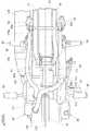
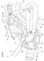
図2は本発明に係る吸気ダクトを説明する鞍乗り型車両の要部左側面図であり、吸気ダクト117は、先端に車両後方に向けて開口するように設けられた吸気口117aと、この吸気口117の下方にダクト取付ブラケット121を介してサブフレーム81に取付けるために設けられたフレーム取付片117bとを備え、センタカバー32(図1参照)及び左側のサイドカバー34(図1参照)と、収納ボックス91との間のスペースに配置されるとともに、スイングアーム52の前端52aより前方に配置されている。即ち、スイングアーム52の前端52aを通る鉛直線120よりも前方に吸気ダクト117が位置し、吸気口117aが収納ボックス91の左側の側面91cの側方に位置している。 FIG. 2 is a left side view of an essential part of the saddle-ride type vehicle for explaining the intake duct according to the present invention. The
図3は本発明に係る吸気ダクト及び排気ダクトを説明する鞍乗り型車両の要部右側面図であり、クランクケース96の右側部に無段変速機97を構成する変速機ケース115が取付けられ、この変速機ケース115内の変速機室130(図5参照)に、無段変速機97を構成する駆動プーリ、従動プーリ、及びこれらの駆動プーリ及び従動プーリに掛け渡されたVベルトからなる無段変速機本体部135(図5参照)が収納されている。 FIG. 3 is a right side view of an essential part of a saddle-ride type vehicle for explaining an intake duct and an exhaust duct according to the present invention. A
変速機ケース115は、変速機室130内に外気を導いて無段変速機本体部を冷却するための吸気ダクト117と、変速機室130内の空気(無段変速機本体部が作動することで温められた空気を含む)を外部に排出する排気ダクト118とが接続され、吸気ダクト117が変速機ケース115の前部上部、排気ダクト118が吸気ダクト117の後方であって変速機ケース115の後部上部に接続されている。 The
吸気ダクト117は、変速機ケース115との接続部から後方へ次第に後上がりとなるように延びている。
排気ダクト118は、先端に車両後方に向けて開口するように設けられた排気口118aと、この排気口118aの下方にダクト取付ブラケット121を介してサブフレーム82に取付けるために設けられたフレーム取付片118bとを備え、変速機ケース115との接続部から後方へ次第に後上がりとなるように延び、センタカバー32(図1参照)及び右側のサイドカバー36(不図示)と、収納ボックス91との間のスペースに配置されるとともに、スイングアーム52の前端52aより前方に配置されている。即ち、スイングアーム52の前端52aを通る鉛直線120よりも前方に排気ダクト118が位置し、排気口118aが収納ボックス91の右側の側面91dの側方に位置している。The
The
図中の符号88はスイングアーム52をスイング自在に支持するためにピボットプレート74に取付けられたピボット軸、127はシリンダヘッド102の下部に一端が接続された排気管、129はブレーキペダルである。
図4は本発明に係るパワーユニットの斜視図であり、パワーユニット24におけるエンジン95の一部(即ち、シリンダブロック101(図2参照)、シリンダヘッド102(図2参照)、ヘッドカバー103(図2参照)等)を除いた部分を示している。 FIG. 4 is a perspective view of the power unit according to the present invention, and a part of the
パワーユニット24におけるクランクケース96の右側部に無段変速機97の変速機ケース115が取付けられ、この変速機ケース115の変速機室130内に無段変速機97の無段変速機本体部135(図5参照)が収納されている。 A
変速機ケース115の上部には、前部に吸気ダクト117(図2参照)が接続される筒状の吸気ダクト接続部115aが上方に側面視でエンジンハンガ86(図3参照)を避けるように斜め前方に向けて(図3も参照)突出させて一体成形され、後部に排気ダクト118(図3参照)が接続される筒状の排気ダクト接続部115bが上方に斜め後方に向けて(図3も参照)突出するように且つ吸気ダクト接続部115aよりも高い位置に一体成形されている。なお、符号115cは吸気ダクト接続部115aの接続口、115dは排気ダクト接続部115bの接続口であり、これらの接続口115c,115dは変速機室130内と連通している。 In the upper part of the
図5は本発明に係るパワーユニットを示す平面図(一部断面図)であり、パワーユニット24は、左クランクケース131及び右クランクケース132からなるクランクケース96と、左クランクケース131の側部に発電機を覆うために取付けられた発電機カバー133と、右クランクケース132の側部に無段変速機97の無段変速機本体部135を収納する変速機ケース115とを備える。
無段変速機本体部135が収納された変速機ケース115の内側は、変速機室130を形成している。FIG. 5 is a plan view (partially sectional view) showing a power unit according to the present invention. The
A
左クランクケース131及び右クランクケース132は、クランク軸136及びパワーユニット24の出力軸138を回転自在に支持し、右クランクケース132及び変速機ケース115は、従動軸137を回転自在に支持している。 The
無段変速機97の無段変速機本体部135は、クランク軸136に取付けられた駆動プーリ141と、従動軸137に取付けられた従動プーリ142と、これらの駆動プーリ141及び従動プーリ142のそれぞれに掛け渡されたVベルト143とを備える。 The continuously variable transmission
駆動プーリ141は、クランク軸136の端部に取付けられた固定半体145と、この固定半体145に対して近づく、あるいは離れるようにクランク軸136にスライド自在にスプライン結合された可動半体146とからなる。 The driving
従動プーリ142は、従動軸137に取付けられた固定半体151と、この固定半体151に対して近づく、あるいは離れるように従動軸137にスライド自在にスプライン結合されるとともに圧縮コイルばね152によって固定半体151に近づくように付勢された可動半体153とからなる。 The driven
クランク軸136が回転すると、駆動プーリ141がクランク軸136と共に回転し、この駆動プーリ141の回転がVベルト143を介して従動プーリ142に伝わり、従動プーリ142の回転と共に従動軸137が回転し、従動137に複数のギヤを介して連結された出力軸138が回転し、この出力軸138に取付けられた駆動スプロケット155が回転し、この駆動スプロケット155にチェーンを介して後輪41(図1参照)に一体的に取付けられた従動スプロケットが回転して後輪41が駆動される。 When the
更に、クランク軸136が回転数が増加すると、可動半体146に隣接するように配置されたウエイト156が遠心力で半径方向外側に移動するため、これに伴って可動半体146が固定半体145に近づく。これにより、駆動プーリ141におけるVベルト143の巻き掛け径が大きくなる。 Further, when the number of rotations of the
このように、駆動プーリ141の巻き掛け径が大きくなると、従動プーリ142の可動半体153は、圧縮コイルばね152の弾性力に抗して固定半体151から離れ、従動プーリ142におけるVベルト143の巻き掛け径は小さくなる。 As described above, when the winding diameter of the
上記したように、Vベルト143の巻き掛け径が、駆動プーリ141では大きくなり、従動プーリ142では小さくなるため、クランク軸136に対して従動軸137の回転が増速される。 As described above, the winding diameter of the V-
上記とは逆に、クランク軸136の回転数が低下すると、Vベルト143の巻き掛け径が、駆動プーリ141では小さくなり、従動プーリ142では大きくなるため、クランク軸136に対して従動軸137の回転が減速される。
以上のように、クランク軸136の回転数に応じて従動軸137の回転数が自動変速される。Contrary to the above, when the rotational speed of the
As described above, the rotational speed of the driven
変速機ケース115は、右クランクケース132に複数のボルト(不図示)で取付けられた内側変速機ケース161と、この内側変速機ケース161に複数のボルト162で取付けられた変速機カバー163とからなり、内側変速機ケース161の上部に吸気ダクト接続部115a及び排気ダクト接続部115bが形成されている。 The
吸気ダクト接続部115a及び排気ダクト接続部115bのそれぞれの接続口115c,115dは共に前後に長い楕円形で、接続口115c,115dが前後に並ぶように配置され、接続口115cは駆動プーリ141の上方、接続口115dは従動プーリ142の上方に位置する。 The
図6は本発明に係る吸気ダクトの配置を示す要部左側面図であり、吸気ダクト117が、変速機ケース115(図3参照)からメインフレーム73の側方を通って、その後、メインフレーム73の上方を通り、収納ボックス91の前部側方まで延びた状態を示している。
排気ダクト118(図3参照)の先端部は、吸気ダクト117と左右対称で基本形状は同一であり、説明は省略する。FIG. 6 is a left side view of the main part showing the arrangement of the intake duct according to the present invention. The
The front end of the exhaust duct 118 (see FIG. 3) is bilaterally symmetrical with the
吸気ダクト117は、その先端部に車両後方に開口する吸気口117aが設けられ、この吸気口117aの下方に、リヤフレーム76に設けられたダクト取付ブラケット121にボルト122で取付けられるフレーム取付片117bが一体に形成されている。 The
吸気口117aは、収納ボックス91の側面91cの側方に、且つ収納ボックス91とサイドカバー34(図1参照)との間の空間170に配置されている。なお、符号125はメインフレーム73にセンタカバー32の前部下部を取付けるカバーブラケットである。 The
図7は本発明に係る吸気ダクトを示す要部斜視図であり、吸気ダクト117の吸気口117aは、車両後方に向けて開口する縦長の三角形状のものである。
このように吸気口117aを縦長の三角形状とすることで、吸気口117aの一辺117cは収納ボックス91の側面91cとほぼ平行にすることで側面91cにより接近させることができ、吸気口117aの一辺117dは下端に対して上端を側面91cに近づけるように傾斜させることで、サイドカバー34(図1参照)の内面に沿わせるようにしてより接近させることができるため、収納ボックス91とサイドカバー34(図2参照)との間の空間170に吸気口117aを配置したことによるサイドカバー34の車体側方への突出量をより小さくすることができる。FIG. 7 is a perspective view of a main part showing an intake duct according to the present invention, and an
Thus, by making the
図8は本発明に係る吸気ダクト及び排気ダクトの配置を示す鞍乗り型車両の要部平面図であり、吸気ダクト117及び排気ダクト118を収納ボックス91の左右に振り分けて配置したことを示している。 FIG. 8 is a plan view of the main part of the saddle-ride type vehicle showing the arrangement of the intake duct and the exhaust duct according to the present invention, and shows that the
詳しくは、吸気ダクト117は、メインフレーム73の側方を通り、メインフレーム73に沿って後方に延び、その後、メインフレーム73の上方を通って収納ボックス91の外周面、即ち、前面91e及び左側の側面91cに沿って後方へ延びている。
また、排気ダクト118は、収納ボックス91の外周面、即ち、前面91e及び右側の側面91dに沿って後方へ延びている。Specifically, the
The
換言すれば、車体の中心を前後方向に延びる車体中心線173を挟んで左右に吸気ダクト117と排気ダクト118とを配置している。なお、符号111はキックペダルである。 In other words, the
図9は本発明に係る吸気ダクトの別実施形態を示す鞍乗り型車両の要部左側面図であり、無段変速機97は、内部に外気を導いて冷却するための吸気ダクト175が接続されている。 FIG. 9 is a left side view of an essential part of a saddle-ride type vehicle showing another embodiment of the intake duct according to the present invention, and the continuously
吸気ダクト175は、後方斜め上方に延びて、メインフレーム73の上方及び収納ボックス91の前方及び左側方を通り、燃料タンク92の前部の左側方で水平又はほぼ水平に後方へ延び、リヤクッションユニット53の上端部53aのリヤフレーム76への取付部の前方に、後方斜め下方に向けて吸気口175aが開口している。 The
図中の符号175bは吸気ダクト175をサブフレーム81に取付けるために吸気ダクト175に一体成形されたフレーム取付片、175c,175dは吸気ダクト175をサイドカバー34(図1参照)に取付けるために吸気ダクト175に一体成形されたカバー取付片である。
図10は本発明に係る排気ダクトの別実施形態を示す鞍乗り型車両の要部右側面図であり、変速機ケース115の後部上部に接続された排気ダクト176は、変速機ケース115との接続部から後方斜め上方に延びて、収納ボックス91の前方及び右側方を通り、燃料タンク92の前部の右側方で水平又はほぼ水平に後方へ延び、リヤクッションユニット53の上端53aのリヤフレーム77への取付部の前方に後方斜め下方に向けて吸気口176aが開口している。 FIG. 10 is a right side view of an essential part of a saddle-ride type vehicle showing another embodiment of the exhaust duct according to the present invention. The
図中の符号128は排気管127の後端に接続されたマフラ、176bは排気ダクト176をサブフレーム82に取付けるために排気ダクト176に一体成形されたフレーム取付片、176c,176dは排気ダクト176をサイドカバー36(不図示)に取付けるために排気ダクト176に一体成形されたカバー取付片である。
図11は本発明に係る吸気ダクト及び排気ダクトの別実施形態を示す鞍乗り型車両の要部平面図であり、吸気ダクト175及び排気ダクト176を収納ボックス91及び燃料タンク92の左右に振り分けて配置したことを示している。 FIG. 11 is a plan view of an essential part of a saddle-ride type vehicle showing another embodiment of the intake duct and the exhaust duct according to the present invention. The
詳しくは、吸気ダクト175は、メインフレーム73の側方を通り、メインフレーム73に沿って後方に延び、その後、メインフレーム73の上方を通って収納ボックス91の前面91e及び側面91cに沿って後方へ延び、更に、燃料タンク92の側方に沿って後方へ延びている。
排気ダクト176は、収納ボックス91の前面91e及び側面91dに沿って後方へ延び、更に、燃料タンク92の側方に沿って後方へ延びている。
換言すれば、車体中心線173を挟んで左右に吸気ダクト175と排気ダクト176とを配置している。Specifically, the
The
In other words, the
以上の図1〜図11に示したように、車体フレーム71にパワーユニット24が取付けられ、このパワーユニット24がベルト式の無段変速機97、詳しくは、無段変速機97の無段変速機本体部135を収納する変速機室130を有し、パワーユニット24に、変速機室130内へ外気を導入する吸気ダクト117,175と、変速機室130内の空気を外部に排出する排気ダクト118,176とが接続された鞍乗り型車両10において、吸気ダクト117,175及び排気ダクト118,176が、共に少なくとも無段変速機本体135(実施例では、無段変速機97、即ち、変速機ケース115、変速機室130、無段変速機本体部135、変速機カバー163)よりも車両後方に延ばされているので、無段変速機本体部135の前方に運転者の脚部のスペースを大きく確保することができる。 As shown in FIGS. 1 to 11, the
以上の図8、図11に示したように、吸気ダクト117,175の吸気口117a,175aと排気ダクト118,176の排気口118a,176aとが、車体の中央を通り前後方向に延びる車体中心線173を挟んで左右に振り分けて配置されているので、吸気口117a,175aと排気口118a,176aとが左右に離れるため、排気口118a,176aから排出された温かい空気を吸気口117a,175aから吸い込みにくくすることができ、無段変速機本体部135を温められていない空気で効果的に冷却することができる。 As shown in FIGS. 8 and 11 above, the
また、無段変速機本体部135の上方にシート31が配置され、このシート31の下方に車体フレーム71に支持される収納ボックス91が配置され、この収納ボックス91を挟んで収納ボックス91の左右に吸気ダクト117,175と排気ダクト118,176とが振り分けて配置されているので、吸気ダクト117,175と排気ダクト118,176との間の収納ボックス91によって、排気ダクト118,176の排気口118a,176aから排出された温かい空気が収納ボックス91で遮られて吸気ダクト117,175の吸気口117a,175aからより一層吸い込まれにくくすることができる。従って、無段変速機本体部135を温められていない空気で一層効果的に冷却することができる。 Further, the
更に、吸気ダクト117,175又は排気ダクト118,176が、収納ボックス91の外周面としての前面91e、側面91c、側面91dに沿うようにして設けられているので、吸気ダクト117,175及び排気ダクト118,176の収納ボックス91の前面91e、側面91c、側面91dからの突出量を小さくすることができ、車体の大型化を防止することができる。 Further, since the
以上の図2、図3、図8〜図11に示したように、エンジン95の後方に、前端が車体フレーム71にスイング自在に取付けられるとともに後端で後輪41を支持するスイングアーム52が設けられ、吸気ダクト117,175又は排気ダクト118,176がスイングアーム52より前方に配置されているので、吸気ダクト117,175及び排気ダクト118,176を短くすることができ、吸気ダクト117,175及び排気ダクト118,176の軽量化を図ることができる。 As shown in FIGS. 2, 3, and 8 to 11, a
図12は本発明に係る吸気ダクト及び排気ダクトの更なる別実施形態を示す鞍乗り型車両の要部平面図であり、図2、図11に示した実施形態と同一構成については同一符号を付け、詳細説明は省略する。
吸気ダクト117及び排気ダクト176は、収納ボックス91及び燃料タンク92の左右に振り分けて配置されている。
即ち、車体中心線173を挟んで左右に吸気ダクト117と排気ダクト176とが配置されている。FIG. 12 is a plan view of an essential part of a saddle-ride type vehicle showing still another embodiment of the intake duct and the exhaust duct according to the present invention. The same reference numerals are given to the same components as those of the embodiment shown in FIGS. Detailed description is omitted.
The
That is, the
詳しくは、吸気ダクト117は、メインフレーム73の側方を通り、メインフレーム73に沿って後方に延び、その後、メインフレーム73の上方を通って収納ボックス91の外周面、即ち、前面91e及び左側の側面91cに沿って後方へ延びている。
排気ダクト176は、収納ボックス91の前面91e及び側面91dに沿って後方へ延び、更に、燃料タンク92の側方に沿って後方へ延びている。Specifically, the
The
図13は本発明に係る吸気ダクト及び排気ダクトの更なる別実施形態を示す鞍乗り型車両の要部左側面図であり、詳しくは、吸気ダクト117は、センタカバー32(図1参照)及び左側のサイドカバー34(図1参照)と、収納ボックス91との間のスペースに配置されるとともに、スイングアーム52の前端52aより前方に配置されている。即ち、スイングアーム52の前端52aを通る鉛直線120よりも前方に吸気ダクト117が位置し、吸気口117aが収納ボックス91の左側の側面91cの側方に位置している。 FIG. 13 is a left side view of an essential part of a saddle-ride type vehicle showing still another embodiment of the intake duct and exhaust duct according to the present invention. Specifically, the
尚、本実施形態では、図8、図11に示したように、吸気口117aと排気口118aとの位置、吸気口175aと排気口176aとの位置を、それぞれ前後方向で同一にしたが、これに限らず、それぞれ前後方向で異なるようにしてもよいし、それぞれ上下方向で異なる位置に配置してもよい。 In this embodiment, as shown in FIGS. 8 and 11, the positions of the
本発明は、無段変速機を備えた鞍乗り型車両に好適である。 The present invention is suitable for a saddle-ride type vehicle equipped with a continuously variable transmission.
10…鞍乗り型車両(自動二輪車)、24…パワーユニット、41…後輪、52…スイングアーム、63…運転者用ステップ、71…車体フレーム、91…収納ボックス、91c,91d,91e…外周面(側面、側面、前面)、97…無段変速機、115…変速機ケース、115a…吸気ダクト接続部、115b…排気ダクト接続部、117,175…吸気ダクト、117a,175a…吸気口、118,176…排気ダクト、118a,176a…排気口、130…変速機室、173…車体中心線。DESCRIPTION OF
Claims (5)
Translated fromJapanese前記吸気ダクト(117)及び前記排気ダクト(118)は、共に前記無段変速機(97)よりも車両後方に延ばされ、
前記吸気ダクト(117)の吸気口(117a)と前記排気ダクト(118)の排気口(118a)とは、車体の中央を通り前後方向に延びる車体中心線(173)を挟んで左右に振り分けて配置されている、
ことを特徴とする鞍乗り型車両。Attached to the body frame(71) is a power unit(24), the power unit(24) has transmission chamber for housing the belt type continuously variable transmission(97) to(130), wherein the power unit(24), wherein an intake duct for introducing outside air into the transmission chamber(130) in(117), the saddle-ride type vehicle and an exhaust duct (118) is connected for discharging air in the transmission chamber(130) within the outside ,
The intake duct (117) and said exhaust duct(118)is if extended both the rear of the vehicle than the continuously variable transmission(97),
The intake port (117a) of the intake duct (117) and the exhaust port (118a) of the exhaust duct (118) are distributed to the left and right with a vehicle body center line (173) passing through the center of the vehicle body and extending in the front-rear direction. Arranged,
A saddle-ride type vehicle characterized by that.
前記吸気ダクト(117)及び前記排気ダクト(118)は、共に前記無段変速機(97)よりも車両後方に延ばされ、The intake duct (117) and the exhaust duct (118) are both extended rearward of the continuously variable transmission (97),
前記無段変速機(97)は吸気ダクト接続部(115a)及び排気ダクト接続部(115b)を備え、前記吸気ダクト接続部(115a)及び排気ダクト接続部(115b)は車両平面視において運転者用ステップ(63,63)の間に配置され、The continuously variable transmission (97) includes an intake duct connection part (115a) and an exhaust duct connection part (115b), and the intake duct connection part (115a) and the exhaust duct connection part (115b) are drivers in a plan view of the vehicle. Between the steps (63, 63) for
前記吸気ダクト(117)及び前記排気ダクト(118)は、前記運転者用ステップ(63,63)よりも車両後方に延ばされている、The intake duct (117) and the exhaust duct (118) are extended to the rear of the vehicle with respect to the driver steps (63, 63).
ことを特徴とする鞍乗り型車両。A saddle-ride type vehicle characterized by that.
Priority Applications (6)
| Application Number | Priority Date | Filing Date | Title |
|---|---|---|---|
| JP2008304386AJP5205231B2 (en) | 2008-11-28 | 2008-11-28 | Saddle riding |
| CN200980146887.2ACN102224063B (en) | 2008-11-28 | 2009-11-17 | Straddled vehicle |
| PCT/JP2009/069462WO2010061750A1 (en) | 2008-11-28 | 2009-11-17 | Straddled vehicle |
| EP09828998.6AEP2353988B1 (en) | 2008-11-28 | 2009-11-17 | Straddled vehicle |
| BRPI0922080ABRPI0922080B1 (en) | 2008-11-28 | 2009-11-17 | vehicle with mounted type saddle |
| ARP090104592AAR075310A1 (en) | 2008-11-28 | 2009-11-27 | VEHICLE TO DRIVE WITH SEAT |
Applications Claiming Priority (1)
| Application Number | Priority Date | Filing Date | Title |
|---|---|---|---|
| JP2008304386AJP5205231B2 (en) | 2008-11-28 | 2008-11-28 | Saddle riding |
Publications (2)
| Publication Number | Publication Date |
|---|---|
| JP2010126058A JP2010126058A (en) | 2010-06-10 |
| JP5205231B2true JP5205231B2 (en) | 2013-06-05 |
Family
ID=42225628
Family Applications (1)
| Application Number | Title | Priority Date | Filing Date |
|---|---|---|---|
| JP2008304386AExpired - Fee RelatedJP5205231B2 (en) | 2008-11-28 | 2008-11-28 | Saddle riding |
Country Status (6)
| Country | Link |
|---|---|
| EP (1) | EP2353988B1 (en) |
| JP (1) | JP5205231B2 (en) |
| CN (1) | CN102224063B (en) |
| AR (1) | AR075310A1 (en) |
| BR (1) | BRPI0922080B1 (en) |
| WO (1) | WO2010061750A1 (en) |
Families Citing this family (1)
| Publication number | Priority date | Publication date | Assignee | Title |
|---|---|---|---|---|
| JP6684840B2 (en)* | 2018-02-09 | 2020-04-22 | 本田技研工業株式会社 | Saddle type vehicle |
Family Cites Families (8)
| Publication number | Priority date | Publication date | Assignee | Title |
|---|---|---|---|---|
| JP3160912B2 (en)* | 1990-12-25 | 2001-04-25 | スズキ株式会社 | Swing case structure of unit swing type engine |
| JP3562279B2 (en)* | 1997-12-15 | 2004-09-08 | スズキ株式会社 | Automatic belt cooling system for scooter type vehicle |
| JP3788155B2 (en)* | 2000-01-11 | 2006-06-21 | スズキ株式会社 | Small vehicle engine unit |
| DE60126197T2 (en)* | 2000-07-05 | 2007-05-24 | Yamaha Hatsudoki K.K., Iwata | Motorcycle, especially scooters |
| JP2002130440A (en)* | 2000-10-25 | 2002-05-09 | Yamaha Motor Co Ltd | Vehicular v belt chamber cooling structure |
| JP3879421B2 (en)* | 2001-03-22 | 2007-02-14 | スズキ株式会社 | Saddle riding four-wheeled vehicle |
| WO2006006435A1 (en)* | 2004-07-08 | 2006-01-19 | Yamaha Hatsudoki Kabushiki Kaisha | Power unit and saddle riding-type vehicle with the same |
| JP4472475B2 (en)* | 2004-09-17 | 2010-06-02 | 川崎重工業株式会社 | Cooling structure for belt converter of rough terrain vehicle |
- 2008
- 2008-11-28JPJP2008304386Apatent/JP5205231B2/ennot_activeExpired - Fee Related
- 2009
- 2009-11-17EPEP09828998.6Apatent/EP2353988B1/ennot_activeNot-in-force
- 2009-11-17WOPCT/JP2009/069462patent/WO2010061750A1/enactiveApplication Filing
- 2009-11-17CNCN200980146887.2Apatent/CN102224063B/ennot_activeExpired - Fee Related
- 2009-11-17BRBRPI0922080Apatent/BRPI0922080B1/ennot_activeIP Right Cessation
- 2009-11-27ARARP090104592Apatent/AR075310A1/enunknown
Also Published As
| Publication number | Publication date |
|---|---|
| CN102224063A (en) | 2011-10-19 |
| EP2353988A1 (en) | 2011-08-10 |
| EP2353988B1 (en) | 2013-11-06 |
| EP2353988A4 (en) | 2012-05-02 |
| BRPI0922080B1 (en) | 2020-01-14 |
| CN102224063B (en) | 2014-03-19 |
| BRPI0922080A2 (en) | 2015-12-15 |
| WO2010061750A1 (en) | 2010-06-03 |
| AR075310A1 (en) | 2011-03-23 |
| JP2010126058A (en) | 2010-06-10 |
Similar Documents
| Publication | Publication Date | Title |
|---|---|---|
| JP5202219B2 (en) | Front structure of saddle-ride type vehicle | |
| JP4953950B2 (en) | Cooling device for small vehicle engine | |
| JP6476301B2 (en) | Power unit for saddle-ride type vehicles | |
| JP2009046017A (en) | Engine unit and saddle-riding type vehicle | |
| JP4887349B2 (en) | Saddle riding | |
| JP5205231B2 (en) | Saddle riding | |
| JP2009019582A (en) | Radiator device for small vehicles | |
| JP5080431B2 (en) | Saddle riding | |
| CN100443702C (en) | Engine exhaust structure of two-wheeled motor vehicle | |
| CN100417572C (en) | Motorcycle | |
| JP4134596B2 (en) | Cooling structure of belt type automatic transmission for scooter type motorcycle | |
| JP3890898B2 (en) | Secondary air supply device for scooter type motorcycle | |
| TWI277555B (en) | Two-wheeled vehicle | |
| JP2007203827A (en) | Vehicle equipped with belt type transmission and leg shield | |
| JP4441389B2 (en) | Exhaust muffler structure in motorcycles | |
| JP5521903B2 (en) | Cooling structure for belt type automatic transmission | |
| JP2014104791A (en) | Cooling device of v belt type non-stage transmission of two wheel vehicle | |
| JP2020157844A (en) | Rear wheel brake device for motorcycle | |
| JP2009103233A (en) | Cooling structure of power transmission device | |
| JP2005153877A (en) | Motorcycle | |
| JP4847508B2 (en) | Scooter type vehicle | |
| JP3813284B2 (en) | Scooter type motorcycle | |
| JP5501416B2 (en) | Transmission cooling duct for saddle riding type vehicles | |
| JP5386021B2 (en) | Transmission cooling duct for saddle riding type vehicles | |
| JP4386304B2 (en) | Scooter type motorcycle |
Legal Events
| Date | Code | Title | Description |
|---|---|---|---|
| A621 | Written request for application examination | Free format text:JAPANESE INTERMEDIATE CODE: A621 Effective date:20101126 | |
| A131 | Notification of reasons for refusal | Free format text:JAPANESE INTERMEDIATE CODE: A131 Effective date:20120911 | |
| A521 | Written amendment | Free format text:JAPANESE INTERMEDIATE CODE: A523 Effective date:20121108 | |
| TRDD | Decision of grant or rejection written | ||
| A01 | Written decision to grant a patent or to grant a registration (utility model) | Free format text:JAPANESE INTERMEDIATE CODE: A01 Effective date:20130212 | |
| A61 | First payment of annual fees (during grant procedure) | Free format text:JAPANESE INTERMEDIATE CODE: A61 Effective date:20130218 | |
| R150 | Certificate of patent or registration of utility model | Ref document number:5205231 Country of ref document:JP Free format text:JAPANESE INTERMEDIATE CODE: R150 Free format text:JAPANESE INTERMEDIATE CODE: R150 | |
| FPAY | Renewal fee payment (event date is renewal date of database) | Free format text:PAYMENT UNTIL: 20160222 Year of fee payment:3 | |
| LAPS | Cancellation because of no payment of annual fees |