JP5202328B2 - Microfabricated catheter - Google Patents
Microfabricated catheterDownload PDFInfo
- Publication number
- JP5202328B2 JP5202328B2JP2008545617AJP2008545617AJP5202328B2JP 5202328 B2JP5202328 B2JP 5202328B2JP 2008545617 AJP2008545617 AJP 2008545617AJP 2008545617 AJP2008545617 AJP 2008545617AJP 5202328 B2JP5202328 B2JP 5202328B2
- Authority
- JP
- Japan
- Prior art keywords
- catheter
- slot
- proximal
- elongated
- tube
- Prior art date
- Legal status (The legal status is an assumption and is not a legal conclusion. Google has not performed a legal analysis and makes no representation as to the accuracy of the status listed.)
- Expired - Fee Related
Links
- 229920000642polymerPolymers0.000claimsdescription44
- 239000000463materialSubstances0.000claimsdescription22
- 229910052751metalInorganic materials0.000claimsdescription19
- 239000002184metalSubstances0.000claimsdescription19
- 230000002093peripheral effectEffects0.000claimsdescription18
- 229920001903high density polyethylenePolymers0.000claimsdescription3
- 239000004700high-density polyethyleneSubstances0.000claimsdescription3
- 239000002861polymer materialSubstances0.000claimsdescription2
- 230000009977dual effectEffects0.000abstract1
- 238000000034methodMethods0.000description11
- 239000003550markerSubstances0.000description9
- 230000006835compressionEffects0.000description5
- 238000007906compressionMethods0.000description5
- 229910001000nickel titaniumInorganic materials0.000description5
- RTZKZFJDLAIYFH-UHFFFAOYSA-NDiethyl etherChemical compoundCCOCCRTZKZFJDLAIYFH-UHFFFAOYSA-N0.000description4
- 239000004952PolyamideSubstances0.000description4
- 229920001477hydrophilic polymerPolymers0.000description4
- HLXZNVUGXRDIFK-UHFFFAOYSA-Nnickel titaniumChemical compound[Ti].[Ti].[Ti].[Ti].[Ti].[Ti].[Ti].[Ti].[Ti].[Ti].[Ti].[Ni].[Ni].[Ni].[Ni].[Ni].[Ni].[Ni].[Ni].[Ni].[Ni].[Ni].[Ni].[Ni].[Ni]HLXZNVUGXRDIFK-UHFFFAOYSA-N0.000description4
- 229920002647polyamidePolymers0.000description4
- 229910001220stainless steelInorganic materials0.000description4
- 239000010935stainless steelSubstances0.000description4
- 239000011248coating agentSubstances0.000description3
- 238000000576coating methodMethods0.000description3
- 150000001875compoundsChemical class0.000description3
- 229920001746electroactive polymerPolymers0.000description3
- -1polyethylenePolymers0.000description3
- 229920002635polyurethanePolymers0.000description3
- 239000004814polyurethaneSubstances0.000description3
- KDLHZDBZIXYQEI-UHFFFAOYSA-NPalladiumChemical compound[Pd]KDLHZDBZIXYQEI-UHFFFAOYSA-N0.000description2
- 229920002614Polyether block amidePolymers0.000description2
- 239000004698PolyethyleneSubstances0.000description2
- 230000001154acute effectEffects0.000description2
- 230000008859changeEffects0.000description2
- 229920001577copolymerPolymers0.000description2
- 238000000227grindingMethods0.000description2
- 230000001965increasing effectEffects0.000description2
- 239000007769metal materialSubstances0.000description2
- BASFCYQUMIYNBI-UHFFFAOYSA-NplatinumChemical compound[Pt]BASFCYQUMIYNBI-UHFFFAOYSA-N0.000description2
- 229920000728polyesterPolymers0.000description2
- 229920000573polyethylenePolymers0.000description2
- 229920001296polysiloxanePolymers0.000description2
- 229920001343polytetrafluoroethylenePolymers0.000description2
- 239000004810polytetrafluoroethyleneSubstances0.000description2
- 230000008569processEffects0.000description2
- 239000012781shape memory materialSubstances0.000description2
- 229920001169thermoplasticPolymers0.000description2
- 229920002725thermoplastic elastomerPolymers0.000description2
- 229920000049Carbon (fiber)Polymers0.000description1
- 229920000106Liquid crystal polymerPolymers0.000description1
- 239000004977Liquid-crystal polymers (LCPs)Substances0.000description1
- 239000004642PolyimideSubstances0.000description1
- 239000004372Polyvinyl alcoholSubstances0.000description1
- 239000004809TeflonSubstances0.000description1
- 229920006362Teflon®Polymers0.000description1
- 229910001080W alloyInorganic materials0.000description1
- 229920000615alginic acidPolymers0.000description1
- 235000010443alginic acidNutrition0.000description1
- 230000015572biosynthetic processEffects0.000description1
- 239000004917carbon fiberSubstances0.000description1
- 238000003486chemical etchingMethods0.000description1
- 229910003460diamondInorganic materials0.000description1
- 239000010432diamondSubstances0.000description1
- 230000000694effectsEffects0.000description1
- 229920002313fluoropolymerPolymers0.000description1
- 239000004811fluoropolymerSubstances0.000description1
- 230000006870functionEffects0.000description1
- PCHJSUWPFVWCPO-UHFFFAOYSA-NgoldChemical compound[Au]PCHJSUWPFVWCPO-UHFFFAOYSA-N0.000description1
- 239000010931goldSubstances0.000description1
- 229910052737goldInorganic materials0.000description1
- 229920013821hydroxy alkyl cellulosePolymers0.000description1
- 230000001939inductive effectEffects0.000description1
- 230000003902lesionEffects0.000description1
- 238000004519manufacturing processMethods0.000description1
- 230000007246mechanismEffects0.000description1
- 239000000155meltSubstances0.000description1
- VNWKTOKETHGBQD-UHFFFAOYSA-NmethaneChemical compoundCVNWKTOKETHGBQD-UHFFFAOYSA-N0.000description1
- 239000000203mixtureSubstances0.000description1
- 239000012768molten materialSubstances0.000description1
- 229910052763palladiumInorganic materials0.000description1
- 229910052697platinumInorganic materials0.000description1
- 229920000412polyarylenePolymers0.000description1
- 229920001721polyimidePolymers0.000description1
- 229920002451polyvinyl alcoholPolymers0.000description1
- 229920000036polyvinylpyrrolidonePolymers0.000description1
- 235000013855polyvinylpyrrolidoneNutrition0.000description1
- 239000001267polyvinylpyrrolidoneSubstances0.000description1
- 238000007789sealingMethods0.000description1
- 229910000679solderInorganic materials0.000description1
- 235000000346sugarNutrition0.000description1
- 150000008163sugarsChemical class0.000description1
- 229910052715tantalumInorganic materials0.000description1
- GUVRBAGPIYLISA-UHFFFAOYSA-Ntantalum atomChemical compound[Ta]GUVRBAGPIYLISA-UHFFFAOYSA-N0.000description1
- BFKJFAAPBSQJPD-UHFFFAOYSA-NtetrafluoroetheneChemical compoundFC(F)=C(F)FBFKJFAAPBSQJPD-UHFFFAOYSA-N0.000description1
- 239000004416thermosoftening plasticSubstances0.000description1
- PAPBSGBWRJIAAV-UHFFFAOYSA-Nε-CaprolactoneChemical compoundO=C1CCCCCO1PAPBSGBWRJIAAV-UHFFFAOYSA-N0.000description1
Images


Classifications
- A—HUMAN NECESSITIES
- A61—MEDICAL OR VETERINARY SCIENCE; HYGIENE
- A61M—DEVICES FOR INTRODUCING MEDIA INTO, OR ONTO, THE BODY; DEVICES FOR TRANSDUCING BODY MEDIA OR FOR TAKING MEDIA FROM THE BODY; DEVICES FOR PRODUCING OR ENDING SLEEP OR STUPOR
- A61M25/00—Catheters; Hollow probes
- A61M25/0043—Catheters; Hollow probes characterised by structural features
- A61M25/0054—Catheters; Hollow probes characterised by structural features with regions for increasing flexibility
- A—HUMAN NECESSITIES
- A61—MEDICAL OR VETERINARY SCIENCE; HYGIENE
- A61M—DEVICES FOR INTRODUCING MEDIA INTO, OR ONTO, THE BODY; DEVICES FOR TRANSDUCING BODY MEDIA OR FOR TAKING MEDIA FROM THE BODY; DEVICES FOR PRODUCING OR ENDING SLEEP OR STUPOR
- A61M25/00—Catheters; Hollow probes
- A61M25/0021—Catheters; Hollow probes characterised by the form of the tubing
- A61M25/0023—Catheters; Hollow probes characterised by the form of the tubing by the form of the lumen, e.g. cross-section, variable diameter
- A61M25/0026—Multi-lumen catheters with stationary elements
- A61M25/0029—Multi-lumen catheters with stationary elements characterized by features relating to least one lumen located at the middle part of the catheter, e.g. slots, flaps, valves, cuffs, apertures, notches, grooves or rapid exchange ports
- A—HUMAN NECESSITIES
- A61—MEDICAL OR VETERINARY SCIENCE; HYGIENE
- A61M—DEVICES FOR INTRODUCING MEDIA INTO, OR ONTO, THE BODY; DEVICES FOR TRANSDUCING BODY MEDIA OR FOR TAKING MEDIA FROM THE BODY; DEVICES FOR PRODUCING OR ENDING SLEEP OR STUPOR
- A61M25/00—Catheters; Hollow probes
- A61M25/0021—Catheters; Hollow probes characterised by the form of the tubing
- A61M25/0023—Catheters; Hollow probes characterised by the form of the tubing by the form of the lumen, e.g. cross-section, variable diameter
- A61M25/0026—Multi-lumen catheters with stationary elements
- A61M25/0032—Multi-lumen catheters with stationary elements characterized by at least one unconventionally shaped lumen, e.g. polygons, ellipsoids, wedges or shapes comprising concave and convex parts
- A—HUMAN NECESSITIES
- A61—MEDICAL OR VETERINARY SCIENCE; HYGIENE
- A61M—DEVICES FOR INTRODUCING MEDIA INTO, OR ONTO, THE BODY; DEVICES FOR TRANSDUCING BODY MEDIA OR FOR TAKING MEDIA FROM THE BODY; DEVICES FOR PRODUCING OR ENDING SLEEP OR STUPOR
- A61M25/00—Catheters; Hollow probes
- A61M25/01—Introducing, guiding, advancing, emplacing or holding catheters
- A61M25/0105—Steering means as part of the catheter or advancing means; Markers for positioning
- A61M25/0133—Tip steering devices
- A61M25/0138—Tip steering devices having flexible regions as a result of weakened outer material, e.g. slots, slits, cuts, joints or coils
- A—HUMAN NECESSITIES
- A61—MEDICAL OR VETERINARY SCIENCE; HYGIENE
- A61M—DEVICES FOR INTRODUCING MEDIA INTO, OR ONTO, THE BODY; DEVICES FOR TRANSDUCING BODY MEDIA OR FOR TAKING MEDIA FROM THE BODY; DEVICES FOR PRODUCING OR ENDING SLEEP OR STUPOR
- A61M25/00—Catheters; Hollow probes
- A61M25/10—Balloon catheters
Landscapes
- Health & Medical Sciences (AREA)
- Life Sciences & Earth Sciences (AREA)
- Biophysics (AREA)
- Pulmonology (AREA)
- Engineering & Computer Science (AREA)
- Anesthesiology (AREA)
- Biomedical Technology (AREA)
- Heart & Thoracic Surgery (AREA)
- Hematology (AREA)
- Animal Behavior & Ethology (AREA)
- General Health & Medical Sciences (AREA)
- Public Health (AREA)
- Veterinary Medicine (AREA)
- Media Introduction/Drainage Providing Device (AREA)
- Materials For Medical Uses (AREA)
- Surgical Instruments (AREA)
Abstract
Description
Translated fromJapanese通常本発明はカテーテルに関する。より具体的には微細加工された要素を含むカテーテルに関する。The present invention generally relates tocatheters . More specifically, it relates to acatheter that includes microfabricated elements.
通常カテーテルのような医療器具はその性能をあげるために、可撓性、剛性及び最小外径、最大内径等の様々な対立する要件が問題になる。通常特に可撓性に関する要求と剛性に関する要求とのバランスの点がある。従って、可撓性、剛性、及びその他の所望の特性間における最適なバランスを備えるカテーテルのような医療器具の改良に対する要求がある。 Usually, medical devices such as catheters are subject to various conflicting requirements such as flexibility, rigidity and minimum outer diameter, maximum inner diameter, etc. in order to increase their performance. There is usually a balance between the requirements for flexibility and the requirements for stiffness. Accordingly, there is a need for improvements in medical devices such as catheters that provide an optimal balance between flexibility, stiffness, and other desired properties.
本発明は可撓性、強度、及びその他の好適な特性に優れる改良されたカテーテルを提供することを目的とする。The present invention seeks to provide an improvedcatheter that excels in flexibility, strength, and other suitable properties.
本発明の実施例において、カテーテルはカテーテルの末端領域からカテーテルの基端領域に向かって延びる長尺状をなす管を含む。長尺状をなす管の外周面を周方向に延びる多数のスロットが長尺状をなす管に沿って設けられる。各スロットは、第1の部分、第2の部分、及びこれらの間の頂点を含む。高分子二重管腔ライナーは長尺状をなす管内に設けられる。各スロットは、隣接するスロットと周方向にずれる。In an embodiment of the invention, the catheter includes an elongate tube extending from the distal region of the catheter toward the proximal region of the catheter. A number of slots extending in thecircumferential direction on the outer peripheral surface of the long tube are provided along the long tube.Each slot includes a first portion, a second portion, and a vertex therebetween. The polymer double lumen liner is provided in a long tube.Each slot is shifted in the circumferential direction from an adjacent slot.
本発明の別例において、カテーテルはカテーテルの末端領域からカテーテルの基端領域に向かって延びる長尺状をなす金属管を含む。長尺状をなす金属管の外周面を周方向に延びる多数の可撓性を誘発するスロットが長尺状をなす金属管に沿って設けられる。各スロットは、第1の部分、第2の部分、及びこれらの間の頂点を含む。高分子スリーブが長尺状をなす金属管の周囲に設けられ、高分子二重管腔ライナーが長尺状をなす金属管内に設けられる。各スロットは、隣接するスロットと周方向にずれる。In another embodiment of the invention, the catheter includes an elongated metal tube extending from the distal region of the catheter toward the proximal region of the catheter. A plurality of slots for inducing flexibility extending in thecircumferential direction on the outer peripheral surface of the long metal tube are provided along the long metal tube.Each slot includes a first portion, a second portion, and a vertex therebetween. A polymer sleeve is provided around the elongated metal tube, and a polymer double lumen liner is provided in the elongated metal tube.Each slot is shifted in the circumferential direction from an adjacent slot.
本発明の別例において、カテーテルは末端部を画定する末端領域と基端部を画定する基端領域とを有する。カテーテルはカテーテルの末端部からカテーテルの基端部に向かって延びる高分子シースを含む。微細加工されたハイポチューブは高分子シースの上方に設けられ、末端部を画定する末端領域と基端部を画定する基端領域とを含む。微細加工されたハイポチューブはカテーテルの末端領域からカテーテルの基端領域に向かって延びる。これにより高分子シースは微細加工されたハイポチューブの末端部から末端側に延びる。微細加工されたハイポチューブは多数の周方向に延びて可撓性を誘発するスロットを含み、スロットは微細加工されたハイポチューブに沿って設けられる。In another example of the present invention, the catheter has a distal region defining a distal end and a proximal region defining a proximal end. The catheter includes a polymeric sheath that extends from the distal end of the catheter toward the proximal end of the catheter. A microfabricated hypotube is provided above the polymeric sheath and includes a distal region defining a distal end and a proximal region defining a proximal end. The microfabricated hypotube extends from the distal region of the catheter toward the proximal region of the catheter. As a result, the polymer sheath extends from the end of the micromachined hypotube to the end. The micromachined hypotube includes a number ofcircumferentially extending slots that induce flexibility, the slots being provided along the micromachined hypotube.
本発明の別例においてカテーテルは長尺状をなすシャフトと、カテーテルの末端領域内に設けられる少なくとも1つの微細加工されたマーカバンドとを含む。
本発明の別例において、カテーテルは長尺状をなす高分子シースを含み、高分子シースは高分子シースを通過して延びる管腔を画定する。バルーンは長尺状をなす高分子シースの末端領域内の長尺状をなす高分子シースに取り付けられる。少なくとも1つの微細加工された圧縮リングが長尺状をなす高分子シースの管腔内のバルーンの基端側に設けられる。In another embodiment of the invention, the catheter includes an elongate shaft and at least one microfabricated marker band provided in the distal region of the catheter.
In another embodiment of the present invention, the catheter includes an elongate polymeric sheath that defines a lumen extending through the polymeric sheath. The balloon is attached to the elongated polymer sheath in the end region of the elongated polymer sheath. At least one micromachined compression ring is provided on the proximal side of the balloon within the lumen of the elongated polymeric sheath.
本発明の別例において、カテーテルはガイドワイヤ管腔及び膨張管腔を画定する内側シャフトと、内側シャフトの上方に設けられる外側シャフトとを含む。外側シャフトは内側シャフトの末端部を越えて末端側に延びる。バルーン内部を画定するバルーンはカテーテルの末端領域内の外側シャフト上に設けられる。微細加工されたハイポチューブはガイドワイヤ管腔内に設けられ、バルーン内部を通過して末端側に延びる。微細加工されたハイポチューブは1つ以上の切り欠きを含み微細加工されたハイポチューブ上に設けられる1つ以上のマーカバンドを収容する。 In another example of the present invention, the catheter includes an inner shaft that defines a guidewire lumen and an inflation lumen, and an outer shaft disposed above the inner shaft. The outer shaft extends distally beyond the distal end of the inner shaft. A balloon defining the balloon interior is provided on the outer shaft in the distal region of the catheter. A micromachined hypotube is provided in the guidewire lumen and extends distally through the interior of the balloon. The micromachined hypotube includes one or more notches and contains one or more marker bands provided on the micromachined hypotube.
本発明の別例において、カテーテルは長尺状をなすシャフトと長尺状をなすシャフト上に設けられるバルーンとを含む。バルーンは長尺状をなすシャフトに連結される基端側胴部と長尺状をなすシャフトに連結される末端側胴部とを含む。末端側胴部及び基端側胴部はそれぞれ可撓性を高める目的で周方向に設けられた多数の切れ込みを含む。In another embodiment of the present invention, the catheter includes a long shaft and a balloon provided on the long shaft. The balloon includes a proximal barrel connected to the elongated shaft and a distal barrel connected to the elongated shaft. Each of the distal end side body portion and the proximal end side body portion includes a large number of notches provided in thecircumferential direction for the purpose of increasing flexibility.
本発明の別例において、医療器具は外側シャフトと外側シャフト内に設けられる内側シャフトとを含む。内側シャフトは外側シャフトの外側シャフト端部を越えて延びる。折りたたみ式ケージは内側シャフトの上方に設けられる。折りたたみ式シャフトは外側シャフト端部に取り付けられる第1の端部と内側シャフト上の取付点に取り付けられる第2の端部とを含む。折りたたみ式ケージは外側シャフトが内側シャフトに対して移動自在な移動自在位置と外側シャフトが内側シャフトに固定されて移動不能である固定位置との間を移動自在である。 In another example of the invention, the medical device includes an outer shaft and an inner shaft provided within the outer shaft. The inner shaft extends beyond the outer shaft end of the outer shaft. A collapsible cage is provided above the inner shaft. The collapsible shaft includes a first end attached to the outer shaft end and a second end attached to an attachment point on the inner shaft. The collapsible cage is movable between a movable position where the outer shaft is movable relative to the inner shaft and a fixed position where the outer shaft is fixed to the inner shaft and cannot move.
本発明の別例において、医療器具は外側シャフトと外側シャフト内に設けられる内側シャフトとを含む。内側シャフトは外側シャフトの外側シャフト端部を越えて延びる。高分子スリーブは内側シャフトの上方に設けられる。高分子スリーブは外側シャフト端部に取り付けられる第1の端部と内側シャフト上の取付点に取り付けられる第2の端部とを含む。高分子スリーブは外側シャフトが内側シャフトに対して回動可能な回動位置と外側シャフトが内側シャフトに固定されて回動不能である固定位置との間を移動自在である。 In another example of the invention, the medical device includes an outer shaft and an inner shaft provided within the outer shaft. The inner shaft extends beyond the outer shaft end of the outer shaft. The polymer sleeve is provided above the inner shaft. The polymeric sleeve includes a first end attached to the outer shaft end and a second end attached to an attachment point on the inner shaft. The polymer sleeve is movable between a rotation position where the outer shaft can rotate with respect to the inner shaft and a fixed position where the outer shaft is fixed to the inner shaft and cannot rotate.
本発明の別例において、医療器具は多数の周方向に延び、且つ可撓性を誘発するスロットを含み、スロットは微細加工されたハイポチューブに沿って設けられる。高分子インサートは微細加工されたハイポチューブによって画定される管腔内に設けられる。高分子インサートは丸みを帯びない径方向の断面を有し、高分子インサート内に設けられる少なくとも1つの管腔を含む。In another embodiment of the invention, the medical device includes a number ofcircumferentially extending and flexible slots that are provided along the micromachined hypotube. The polymeric insert is provided in a lumen defined by a micromachined hypotube. The polymeric insert has a non-rounded radial cross section and includes at least one lumen disposed within the polymeric insert.
本発明の別例において、カテーテルはハイポチューブ管腔を有する長尺状をなすハイポチューブを含む。長尺状をなすハイポチューブはカテーテルの末端領域からカテーテルの基端領域に向かって延び、長尺状をなすハイポチューブ内に設けられる多数のスロットを含む。膨張可能なバルーンが長尺状をなすハイポチューブの末端領域の周囲に設けられる。外側シースは膨張可能バルーンの基端側に設けられる。外側シースは長尺状をなすハイポチューブの少なくとも末端領域を覆い、これにより外側シースは複数のスロットを熱融着し、ハイポチューブの管腔は膨張可能バルーンを膨張及び収縮させるために使用可能となる。 In another embodiment of the invention, the catheter includes an elongated hypotube having a hypotube lumen. The elongated hypotube extends from the distal region of the catheter toward the proximal region of the catheter and includes a number of slots provided within the elongated hypotube. An inflatable balloon is provided around the distal region of the elongated hypotube. The outer sheath is provided on the proximal side of the inflatable balloon. The outer sheath covers at least the distal region of the elongated hypotube so that the outer sheath can heat seal the slots and the hypotube lumen can be used to inflate and deflate the inflatable balloon. Become.
本発明の別例において微細加工されたハイポチューブは微細加工されたハイポチューブの第1の部分内に設けられる第1の複数のスロットと、微細加工されたハイポチューブの第2の部分内に設けられる第2の複数のスロットとを含む。スロットは微細加工されたハイポチューブの外周面を少なくとも部分的にして、且つ周方向に延びる。第2の複数のスロットは第1の複数のスロット内の隣接するスロット間の間隔より小さい間隔を間に有する隣接したスロットを含む。 In another embodiment of the invention, the micromachined hypotube is provided in a first plurality of slots provided in a first portion of the micromachined hypotube and in a second portion of the micromachined hypotube. And a second plurality of slots. The slot extends circumferentially at least partially on the outer peripheral surface of the micromachined hypotube. The second plurality of slots includes adjacent slots having a spacing therebetween that is less than the spacing between adjacent slots in the first plurality of slots.
本発明の別例において、微細加工されたハイポチューブは微細加工されたハイポチューブ内に設けられた多数のスロットを有する。スロットは外側表面か内側表面に向かって延び、多数のスロットのそれぞれは軸線に対して鋭角をなして延びる第1の部分と第1の部分に少なくとも略直交して設けられる第2の部分とを含む。 In another embodiment of the invention, the micromachined hypotube has a number of slots provided in the micromachined hypotube. The slot extends toward the outer surface or the inner surface, and each of the plurality of slots includes a first portion extending at an acute angle with respect to the axis and a second portion provided at least substantially orthogonal to the first portion. Including.
本発明の別例において、微細加工されたハイポチューブは内側表面、外側表面、及び微細加工されたハイポチューブ上に設けられる周方向に伸びるスロットを備える。周方向に延びるスロットはそれぞれ内側表面にて第1の径を有し、外側表面にて第2の径を有し、第2の径は第1の径よりも大きい。In another example of the present invention, the micromachined hypotube comprises an inner surface, an outer surface, and acircumferentially extending slot provided on the micromachined hypotube. Each of thecircumferentially extending slots has a first diameter on the inner surface and a second diameter on the outer surface, the second diameter being larger than the first diameter.
本発明の別例において、微細加工されたハイポチューブは軸線を有する。多数のスロットは軸線に対して少なくとも略直交して設けられる。少なくともスロットのうちいくつかは第1の端部及び第2の端部を有し、これらのスロットの第1の端部はスロットの第2の端部に向かって延びるボタンを備える。 In another embodiment of the invention, the micromachined hypotube has an axis. The multiple slots are provided at least substantially perpendicular to the axis. At least some of the slots have a first end and a second end, and the first end of these slots includes a button extending toward the second end of the slot.
本発明に関する上記の概要は、本発明の開示された実施例や実施の全てについて記載している訳ではない。以下の図面や詳細な説明において、実施例についてより詳細に例示される。 The above summary of the present invention is not intended to describe each disclosed embodiment or every implementation of the present invention. Examples are described in more detail in the following drawings and detailed description.
本発明は、添付の図面に関する以下の様々な実施例の詳細な説明を鑑みることにより、より深く理解されるであろう。
以下に定義する用語については、請求項または本明細書のいずれかの個所に異なる定義がある場合を除き、以下の定義が適用されるものとする。The present invention will be better understood in view of the following detailed description of various embodiments with reference to the accompanying drawings.
For the terms defined below, the following definitions shall apply unless otherwise defined in the claims or elsewhere in this specification.
本願に記載されるすべての数字は、明示的に記載されているか否かにかかわらず、「約」という語を含んでいるものとされる。「約」という語は、通常、記載された数値と同等であると当業者が判断するであろう数値の範囲(すなわち、同一の機能または結果を生ずる数値の範囲)を指す。多くの場合において、「約」という語は、最も近い有効数字の周囲の数字を含む。 All numbers set forth in this application are intended to include the word “about” whether or not explicitly stated. The term “about” usually refers to a range of numerical values (ie, a range of numerical values that yields the same function or result) that would be deemed to be equivalent by the skilled artisan. In many cases, the term “about” includes numbers around the nearest significant figure.
指標となる数値範囲を記載する場合、当該範囲のすべての数値を含むものとする。(例えば、1〜5の場合、1,1.5,2,2.75,3,3.80,4,5を含む。)
本明細書及び添付の特許請求の範囲において使用されるように、単数形の「1つの(a)」、「1つの(an)」、及び「その(the)」は、内容が明らかにそうではないものを示さない限りは、複数形の対象を含むことに留意すべきである。本明細書および添付の特許請求の範囲に使用される場合において、「又は」という語は、内容が明らかにそうではないものを示さない限りは、「及び/又は」という意味で用いられる。When describing a numerical range that serves as an indicator, all numerical values in the range shall be included. (For example, in the case of 1-5, 1,1.5,2,2.75,3,3.80,4,5 are included.)
As used herein and in the appended claims, the singular forms “a”, “an”, and “the” are clearly It should be noted that the plural forms are included unless otherwise indicated. As used in this specification and the appended claims, the word “or” is used in the sense of “and / or” unless the content clearly indicates otherwise.
以下の説明は、図面を参照して読まれるべきである。なお、各図面においては、類似する要素については、類似する符号を付す。図面は、必ずしも寸法比率が等しいものではなく、本発明により請求される実施形態の例を示したものである。 The following description should be read with reference to the drawings. In addition, in each drawing, the same code | symbol is attached | subjected about a similar element. The drawings are not necessarily to scale and are illustrative of embodiments claimed by the present invention.
通常本発明は微細加工されたハイポチューブやその他の微細加工された要素を含む医療器具に関する。様々な微細加工されたハイポチューブは本発明の範囲内にあり、ここで開示される医療器具において有用である。図1乃至5は本発明の範囲内において意図されるような特定の微細加工されたハイポチューブを示すがこれらに限定されるものではない。 The present invention generally relates to medical devices that include micromachined hypotubes and other micromachined elements. A variety of microfabricated hypotubes are within the scope of the present invention and are useful in the medical devices disclosed herein. 1-5 illustrate, but are not limited to, certain microfabricated hypotubes as contemplated within the scope of the present invention.
図1は基端部14を画定する基端領域12及び末端部18を画定する末端領域16を有する微細加工されたハイポチューブ10を示す。微細加工されたハイポチューブ10は、図から明瞭なように、ハイポチューブ10の長さ方向に延びる軸線20を有する。1つ以上のスロット22が微細加工されたハイポチューブ10の部分に沿って設けられる。図示の実施例において、スロット22は軸線20と少なくとも略直交して配置される。別例において、スロット22は軸線20に対して角度を設けて配置されるか、軸線20に対して平行であってもよい。 FIG. 1 shows a
各スロット22は微細加工されたハイポチューブ10の外周面を部分的にのみ延びる。別例において、各スロット22は微細加工されたハイポチューブの外周面の約半分にわたって延びてもよい。別例において、例えば可撓性の向上が最も重要である場合において各スロット22は外周面の半分以上にわたって延びてもよい。逆に、可撓性をある程度犠牲にして柱の付加的な剛性が要求される場合において、各スロット22は微細加工されたハイポチューブ10の外周面の半分以下にわたって延びるものと考えられる。 Each
各スロット22が微細加工されたハイポチューブ10の外周面の比較的短い部分にわたってしか延びてない場合に、2,3以上のスロット22が微細加工されたハイポチューブ10に沿った軸方向の位置の外周面に周方向に設けられるものと考えられる。実施例において各スロット22は微細加工されたハイポチューブの全体にわたって延びてもよい。実施例において、1つ以上のスロット22はそれぞれ微細加工されたハイポチューブ10の壁厚以下の深みを有してもよい。Where each
各スロット22は対24,即ち第1のスロット26及び第2のスロット28を含む対24として考えられるものといえる。図示の実施例において、第1のスロット26は微細加工されたハイポチューブ10上の第1の周方向の位置を有し、第2のスロット28は第1の周方向の位置から回動された第2の周方向の位置を占める。図示の実施例において、第2のスロット28は第2のスロット28から約90°回動されてもよい。別例において、特に例えば第1のスロット26及び第1のスロット28が図示の長さより長い場合でも短い場合でも周方向の回動は変化する。Each
図示のように実施例において各スロット22は形状が矩形であってもよい。実施例において、各スロット22は半円形状のように湾曲されてもよい。実施例において、各スロット22は菱形であってもよい。各スロット22は例えば鋸切断、レーザー、或いは放電加工機(EDM)のような好適な技術を使用して形成可能である。付加的な好適な技術は化学エッチング及び研磨研削(abrasive grinding )を含む。 As shown, in the embodiment, each
微細加工されたハイポチューブ10は好適な高分子材料や金属材料から形成可能である。実施例において、微細加工されたハイポチューブ10は例えば炭素繊維、液晶高分子、ポリイミド等のような好適、且つ堅固な高分子化合物から形成可能である。実施例において、微細加工されたハイポチューブ10は例えばステンレス鋼のような金属材料やニチノールのようなニッケルチタン合金、或いはその他の金属の形状記憶材料や高分子化合物の形状記憶材料から形成可能である。微細加工されたハイポチューブ10は所望の態様により金属管及び高分子化合物の管の組み合わせを含んでもよい。 The
微細加工されたハイポチューブ10は特定の実施例の要件を満たすべく必要とされる好適な長さ、幅、材料の厚み、及びスロットの寸法を有するように形成可能である。微細加工されたハイポチューブ10に関してその製造方法を含む更なる詳細が例えば米国特許第6766720号明細書及び米国特許出願公開第20040181174A2号明細書に開示され、そのそれぞれの全体がここで開示されたものとする。 The
図1においてスロット22のそれぞれは微細加工されたハイポチューブ10内において均等に軸に沿って間隔をおいて配置される。図2は実施例においてスロット間の間隔が変更されたものを示す。 In FIG. 1, each of the
特に図2は基端部34を画定する基端領域32及び末端部38を画定する末端領域36を有する、微細加工されたハイポチューブ30を示す。
微細加工されたハイポチューブ30はハイポチューブ30の部分にわたって延びる軸線40を有する。多くのスロット42が微細加工されたハイポチューブ10の部分に沿って設けられる。図示の実施例において、スロット42は軸線40に少なくとも略直交して配置される。別例において、スロット42は軸線40に対して角度を設けて配置されてもよい。In particular, FIG. 2 shows a micromachined hypotube 30 having a
The micromachined hypotube 30 has an
各スロット42は微細加工されたハイポチューブ30の外周面を部分的にのみ延びる。別例において、各スロット42は微細加工されたハイポチューブの外周面の約半分にわたって延びてもよい。別例において各スロット42は可撓性及び剛性の相対的な重要度に応じて外周面を半分以下にわたって延びても、これとは逆に半分以上にわたって延びてもよい。図1に関して前述したように、各スロット42は隣接するスロット42と周方向にずれてもよい。Each slot 42 extends only partially on the outer peripheral surface of the micromachined hypotube 30. In another example, each slot 42 may extend about half of the outer periphery of the micromachined hypotube. In another example, each slot 42 may extend less than half of the outer peripheral surface depending on the relative importance of flexibility and rigidity, or vice versa. As described above with reference to FIG. 1, each slot 42 may becircumferentially offset from an adjacent slot 42.
前述したように、図2は別例におけるスロット間の間隔を示す。基端領域32において例えば各スロット42は対44,即ち第1のスロット46及び第2のスロット48を含む対44として考えられる。同様に末端領域36において各スロットは対50,即ち第1のスロット52及び第2のスロット54を含む対50として考えられる。図2において明瞭なように対44の第1のスロット46及び第2のスロット48の間の軸方向の間隔は対50の第1のスロット52及び第2のスロット54の間の軸方向の間隔より大きい。これらは末端領域36内において比較的高い可撓性をもたらすために実施されてもよい。 As mentioned above, FIG. 2 shows the spacing between slots in another example. In the
実施例において、基端領域32におけるスロット間の間隔は第1の連続体であり、末端領域36におけるスロット間の間隔は第2のより小さな連続体である。実施例において、スロット間の間隔は基端領域32から末端領域36に向かって段状に変化してもよい。実施例において、スロット間の間隔は基端領域32から末端領域36に向かってより連続して変化してもよい。 In an embodiment, the spacing between slots in the
図3は別例におけるスロットのパターンを示す。特に図3は基端領域58及び末端領域60を有する微細加工されたハイポチューブ56を示す。軸線62は微細加工されたハイポチューブ56にわたって延びる。微細加工されたハイポチューブ56は多数のスロット64を含む。図から明瞭なように各スロット64は第1の部分66,第2の部分68,及びこれらの間の頂点70を含む。図示のように実施例において軸方向に並べられた複数のスロット64の頂点70は軸線62と平行な線72に沿って設けられる。 FIG. 3 shows a slot pattern in another example. In particular, FIG. 3 shows a
図から明瞭なように第1の部分66は線72に対して鋭角をなし、第2の部分68は第1の部分66に対して少なくとも略直交する。実施例において、第1の部分66及び第2の部分68は線72に対して類似の角度をなしてもよいが第1の部分66及び第2の部分68の間において約90°以下の角度をなしてもよい。別例において第1の部分66及び第2の部分68はこれらの間において約90°より大きな角度をなしてもよい。図1及び2を参照して上述したように、隣接するスロット64は周方向にずれてもよい。As is clear from the figure, the
図4は末端部78を画定する末端領域76及び基端部82を画定する基端領域80を有する微細加工されたハイポチューブ74を示す。微細加工されたハイポチューブはハイポチューブにわたって延びる軸線84を画定する。微細加工されたハイポチューブ74は内側表面86及び外側表面88を有する。多数の先端ほど細くなるように形成されたスロット90が微細加工されたハイポチューブ74内に設けられ、少なくとも略周方向に並べられる。即ち軸線84に対して少なくとも略直交する。図1及び2を参照して上述したように隣接する先端ほど細くなるように形成されたスロット90は周方向にずれてもよい。FIG. 4 shows a
図から明瞭なように先端ほど細くなるように形成されたスロット90は内側表面86にて対向する下端部92を有し、外側表面88にて対向する上端部94を有する。先端ほど細くなるように形成されたスロット90は先端ほど細くなるように形成された各スロット90が軸線84に対して少なくとも略直交する主寸法、及び主寸法と直交する副寸法を有するように構成される。実施例において主寸法は先端ほど細くなるように形成されたスロット90の長さと考えられ、副寸法は先端ほど細くなるように形成されたスロットの幅と考えられる。図示のように実施例において、先端ほど細くなるように形成された各スロット90は副寸法を有する。或いは外側表面88にて対向する上端部94間において副寸法より大きい幅を有するか、内側表面86にて同一の先端ほど細くなるように形成されたスロット90の対向する下端部92間における幅を有する。実施例において、先端ほど細くなるように形成されたスロット90の外側表面88における幅は対応する内側表面86の幅と比較して約二倍であってもよい。 As is clear from the figure, the
外側表面88において比較的幅広の開口部を有する先端ほど細くなるように形成されたスロット90により、微細加工されたハイポチューブ74は対向する上端部94が相互に接触するに先立って更に屈曲可能であるため、微細加工されたハイポチューブ74において比較的高い可撓性が得られる。外側表面に比較的狭小な開口部を備える先端ほど細くなるように形成されたスロット90を設けることにより、微細加工されたハイポチューブ74に圧縮力が作用されると先端ほど細くなるように形成されたスロット90の底端部が相互に接触するため、微細加工されたハイポチューブ74において比較的高い支柱の剛性が得られる。対向する下端部92とこれらに対応する、対向する上端部94間の相対的距離を変化させることにより、可撓性と剛性との間のバランスが実施例において最適化可能である。 Due to the
図示のように実施例において先端ほど細くなるように形成された各スロット90の端部は同様に先端ほど細くなるように形成されてもよい。別例においてスロットの端部は先端ほど細くなるように形成されなくてもよい。先端ほど細くなるように形成された各スロット90は微細加工されたハイポチューブ74の外周面を部分的にのみ延びる。実施例において先端ほど細くなるように形成された各スロット90は微細加工されたハイポチューブ74の外周面の約半分にわたって延びてもよい。別例において、先端ほど細くなるように形成された各スロット90は可撓性及び剛性の相対的な重要度に応じて半分以下にわたって延びても、それとは逆に半分以上にわたって延びてもよい。図1に関して前述したように、各スロット90は隣接するスロット90と周方向にずれてもよい。As shown in the drawing, the end of each
図5は基端部100を画定する基端領域98及び末端部104を画定する末端領域102を有する微細加工されたハイポチューブ96を示す。軸線106は微細加工されたハイポチューブ96にわたって延びる。多数のスロット108は微細加工されたハイポチューブ96内に設けられ、少なくとも略周方向に並べられる。即ち軸線106に対して少なくとも略直交する。図1及び2を参照して上述したように隣接したスロット108は周方向にずれてもよい。FIG. 5 shows a micromachined hypotube 96 having a
図から明らかなように、各スロット108は基端部110及び末端部112を含む。任意の数のスロット108は基端部110及び末端部112の少なくとも1つの上に突出部やボタン114を含んでもよい。これらのボタン114は微細加工されたハイポチューブ96と一体的に形成可能である。実施例において、ボタン114は微細加工されたハイポチューブ96の形成に続いて付加されてもよい。これらの実施例において、ボタン114は少量の半田のような溶融物質や、微細加工されたハイポチューブ96が形成される材料であるステンレス鋼やニチノールを含むか、これらから形成可能である。実施例において、ボタン114は放電加工機(EDM)により形成されてもよい。 As can be seen, each slot 108 includes a
図示のように実施例においてボタン114がスロット108の基端部110に沿って設けられるか形成されてもよい。別例においてボタン114はスロット108の末端部112に沿って設けられてもよい。ボタン114は任意の数のスロット108の基端部110に沿って、及び任意の数の別のスロット108の末端部112に沿って設けられてもよいものと考えられる。ボタン114の数及び配置は所望の水準の支柱の支持を得られるように変更可能である。 As shown, a
図6乃至11はここで開示される微細加工されたハイポチューブ10,30,56,74,96の使用例を示す。図6は基端部120を画定する基端領域118及び末端部124を画定する末端領域122を有するカテーテル116を示す。カテーテル116は様々なカテーテルの1つであるが、好適には血管内カテーテルである。血管内カテーテルの例はバルーンカテーテル、アテローム切除術用カテーテル、ステント搬送カテーテルを含み、これらは自己拡張型ステント、フィルタ搬送カテーテル、診断用カテーテル、ガイドカテーテルの使用のために調整される。図6はバルーンカテーテルを示すが、本発明はこれに限定されるものではない。ハブ126は基端部120の近傍のカテーテル116に固定される。バルーン128は末端領域122内のカテーテル116に固定される。ハブ126及びバルーン128は周知の構成である。 6 through 11 show examples of the use of the
図示の実施例において、ガイドワイヤポート130はカテーテル116内のバルーン128の基端側に設けられるが、ハブ126の末端側である。ガイドワイヤポート130はガイドワイヤ管腔(この図には示さない)がカテーテル116の長さ方向にわたって延びる場合においても、カテーテル116の末端部124に比較的近接して設けられカテーテル116に交換が迅速に行われるようにしてもよい。 In the illustrated embodiment, guidewire port 130 is provided proximal to
実施例において、カテーテル116は長尺状をなすシャフト132を含み、シャフト132はハブ126からカテーテル116の少なくとも末端領域122まで延びるか、末端部124まで延びる。長尺状をなすシャフト132は好適な材料からなる。実施例において、長尺状をなすシャフト132は図1乃至5に関して上述したような微細加工されたハイポチューブであってもよい。明瞭単純に示すため、スロットは図6に図示しない。図9及び10に関して後述するように、カテーテル116は長尺状をなすシャフト132の内部の1つ以上の高分子要素を含んでもよい。 In an embodiment, the catheter 116 includes an
図7はハブ126の一部を含む、基端領域118の一部を示す部分断面図である。微細加工されたハイポチューブ134は図から明らかなように、ハブ126から末端側に延びる。上述した微細加工されたハイポチューブの一部と同様に、微細加工されたハイポチューブ134は多数の周方向に延びるスロット135を含む。スロット135は図1に示すものと類似するものとして示されるが、多くのその他の構成が考えられるものと認識される必要がある。FIG. 7 is a partial cross-sectional view showing a portion of the
微細加工されたハイポチューブ134は複数の開口部136も含む。1つ以上の開口部136が微細加工されたハイポチューブ134の外周面に間隔をおいて設けられてもよい。実施例において、全部で4つの開口部136が微細加工されたハイポチューブ134の外周面に等間隔に設けられてもよい。別例において、4つ以下、又は4つ以上の開口部136が含まれてもよい。図示の開口部136は円形であるが、その他の形状も考えられる。 The
開口部136は微細加工されたハイポチューブ134内に設けられ、微細加工されたハイポチューブ134と微細加工されたハイポチューブ134内に設けられる高分子ライナー(より詳細に後述する)との間において付加的な固定点を構成する。実施例において、
付加的な高分子材料が開口部136内に溶融され高分子ライナーを微細加工されたハイポチューブ134に固定する。An
Additional polymeric material is melted into the
図8はガイドワイヤポート130(図7)の両側に対応する、微細加工されたハイポチューブ134の別の断面を示す。微細加工されたハイポチューブ134のこの部分はガイドワイヤ開口部138を含み、開口部138はガイドワイヤポート130と並ぶように構成及び配置される。これにより微細加工されたハイポチューブ134の内部への進入が可能となる。ガイドワイヤ開口部138は図8において若干一般化されているが、形成方法により湾曲した形状や半円形状を有してもよいものと認識される必要がある。1つ以上の開口部140がガイドワイヤ開口部138のちょうど基端側に設けられてもよく、1つ以上の開口部142がガイドワイヤ開口部138のちょうど末端側に設けられてもよい。 FIG. 8 shows another cross-section of
開口部140及び142が微細加工されたハイポチューブ134の外周面に間隔をおいて設けられてもよい。実施例において、全部で4つの開口部140及び全部で4つの開口部142が微細加工されたハイポチューブ134の外周面に等間隔に設けられてもよい。別例において、4つ以下、又は4つ以上の開口部140及び142が含まれてもよい。図示の開口部140及び142は円形であるが、その他の形状も考えられる。 The
開口部140及び142は微細加工されたハイポチューブ134内に含まれ、微細加工されたハイポチューブ134とその内部に設けられた高分子ライナーとの間において付加的な固定点を構成する。実施例において、付加的な高分子材料が開口部140及び142内において溶融され高分子ライナーを微細加工されたハイポチューブ134に固定する。 The
図9は末端領域122の一部を示す部分断面図であり、微細加工されたハイポチューブ134の他バルーン128の一部を示す。1つ以上の開口部144がバルーン128の基端部146のちょうど基端側に設けられてもよい。開口部144は微細加工されたハイポチューブ134の外周面に間隔をおいて設けられてもよい。実施例において、全部で4つの開口部144が微細加工されたハイポチューブ134の外周面に等間隔に設けられてもよい。別例において、4つ以下、又は4つ以上の開口部144が含まれてもよい。図示の開口部144は円形であるが、その他の形状も考えられる。 FIG. 9 is a partial cross-sectional view showing a part of the
開口部144は微細加工されたハイポチューブ134内に含まれ、微細加工されたハイポチューブ134とその内部に設けられた高分子ライナーとの間において付加的な固定点を構成する。実施例において、付加的な高分子材料が開口部144内において溶融され高分子ライナーを微細加工されたハイポチューブ134に固定する。 The
図10は図6において線10−10における断面図であり、長尺状をなすシャフト132(図6)の構成を示す。図から明らかなように、高分子ライナー148は微細加工されたハイポチューブ134内に設けられる。図示の実施例において、高分子ライナー148はガイドワイヤ管腔150及び膨張管腔152を含む。実施例において、高分子ライナー148はカテーテル116(図6)の使用目的によって決定されるように、より多くの数の管腔、或いはより少ない数の管腔を含んでもよい。 FIG. 10 is a cross-sectional view taken along line 10-10 in FIG. 6 and shows the configuration of the elongated shaft 132 (FIG. 6). As is apparent from the figure, the
高分子ライナー148は好適な高分子材料から形成可能である。好適な材料の例はポリエチレン、ポリウレタン、弾性ポリアミド、ブロックポリアミド/エーテル(例、登録商標名PEBAX)、シリコン、共重合体、登録商標名ARNITELとして入手可能なポリエステル熱可塑性エラストマーのような熱可塑性高分子を含む。特定の実施例において、高分子ライナー148は高密度ポリエチレンから形成可能である。高分子ライナー148が高密度ポリエチレンから形成される場合において、同一の材料が開口部136(図7)、開口部140及び142(図8)、及び開口部144(図9)内にて溶融すべく使用可能であり、これにより高分子ライナー148を微細加工されたハイポチューブ134に固定する。 The
図11は図6において線11−11における断面図であり、ガイドワイヤポート(136)と関係する長尺状をなすシャフト132(図6)の詳細な構成を示す。図11において微細加工されたハイポチューブ134及び高分子ライナー148は研磨、研削されるか、或いは仕上げされるか、開口部154を設ける。開口部154によりカテーテル116の外部の位置からガイドワイヤ管腔150に進入が可能となる。 FIG. 11 is a cross-sectional view taken along line 11-11 in FIG. 6, and shows a detailed configuration of the elongated shaft 132 (FIG. 6) related to the guide wire port (136). In FIG. 11, the micromachined hypotube 134 and
図12乃至15はここで開示される微細加工されたハイポチューブ10,30,56,74,96の使用の別例を示す。図12は基端部160を画定する基端領域158及び末端部164を画定する末端領域162を有するカテーテル156を示す。カテーテル156は様々なカテーテルの1つであるが、好適には血管内カテーテルである。血管内カテーテルの例はバルーンカテーテル、アテローム切除術用カテーテル、ステント搬送カテーテル、フィルタ搬送カテーテル、診断用カテーテル、及びガイドカテーテルを含む。 FIGS. 12-15 illustrate another example of the use of the
カテーテル156は後述するように1つ以上の構成要素を含む。図示のように、カテーテル156はガイドワイヤ管腔168及び膨張管腔170を含むが、実施例においてカテーテル156は付加的な管腔を含んでもよい。実施例において、カテーテル156がバルーンカテーテルである場合にはカテーテル156はガイドワイヤ管腔としても膨張管腔としても使用可能な1つの管腔のみを含んでもよい。明瞭にするためにバルーンは図12に示されない。カテーテル156はガイドワイヤ管腔168の内部に進入可能にするガイドワイヤポート166も含む。
図13及び14は図12の断面図である。図13は図12の基端領域158の断面図であり、図14は図12の末端領域162の断面図である。図13に明瞭に示すようにカテーテル156はガイドワイヤ管腔168及び膨張管腔170を画定する内側高分子ライナー172、外側高分子シース176、及びこれらの間に設けられる微細加工されたハイポチューブ174を含む。微細加工されたハイポチューブ174はここで開示される位置、構成、及びスロットの密度に関するどの構造を含んでもよい。13 and 14 are sectional views of FIG. 13 isa cross-sectional view of the
図14はガイドワイヤポート166(図12)の末端側における断面図であるが、図から明らかなように、微細加工されたハイポチューブ174の一部のみがあることを示す。特に上部はガイドワイヤ(図示しない)と干渉してしまうためガイドワイヤ管腔168への進入が可能となるように取り除かれている。 FIG. 14 is a cross-sectional view of the distal side of the guidewire port 166 (FIG. 12), but as can be seen, only a portion of the
図15は基端部178、末端領域180、及び末端部182を有する、微細加工されたハイポチューブ174の側面図である。図から明らかなように、材料の大部分は末端領域180から取り除かれて形状184をなす。実施例において、材料は例えば研削、切断、レーザー等の好適な技術を使用して末端領域180から取り除かれてもよい。実施例において、形状184はこれに代えて材料の除去よりはむしろ微細加工されたハイポチューブ174の末端領域180を圧壊させることにより形成されてもよい。しかしながら、ガイドワイヤ(図示しない)が形状184内に進入する場合にガイドワイヤが微細加工されたハイポチューブ174の内部から微細加工されたハイポチューブ174の外部に向かって通過するように、圧壊された部分にドリルやその他の方法により開口部を形成する必要がある。 FIG. 15 is a side view of a
図16乃至18はここで開示される微細加工されたハイポチューブの使用の別例を示す。図16は基端部190を画定する基端領域188及び末端部194を画定する末端領域192を有するカテーテル186を示す。図示のように、カテーテル186はオーバーザワイヤ型カテーテルやシングルオペレータエクスチェンジ型(SOE)カテーテルであるが、これらに限定されるものではない。カテーテル186は基端部190から末端部194に向かって延びる高分子シース196を含む。図17及び18にも示すように微細加工されたハイポチューブ30(図2)は高分子シース196の上方において使用される。 FIGS. 16-18 illustrate another example of the use of the microfabricated hypotube disclosed herein. FIG. 16 shows a
高分子シース196は好適な高分子材料から形成可能である。好適な材料の例はポリエチレン、ポリウレタン、高密度ポリウレタン、弾性ポリアミド、ブロックポリアミド/エーテル(例、登録商標名PEBAX)、シリコン、共重合体、登録商標名ARNITELとして入手可能なポリエステル熱可塑性エラストマーのような熱可塑性高分子を含む。 The
実施例において、高分子シース196は高い可撓性を備えるがカテーテル186を体腔を押圧して通過させるための柱の非剛性を備えるように特定の材料から特定の寸法に形成可能である。微細加工されたハイポチューブ32は過剰に影響を及ぼす可撓性を備えることなく所望のレベルの柱の剛性を備える。 In an embodiment, the
実施例において、微細加工されたハイポチューブ32の末端部38はカテーテル186の末端部194の基端側に設けられ、末端部194の可撓性への影響を抑止する。実施例において、微細加工された32の末端部38は末端部194から少なくとも約4センチメートルの部分であって末端部194から約20センチメートル未満の部分に設けられる。微細加工されたハイポチューブ32の末端部38はカテーテル186の末端部194から離間し過ぎている場合に押圧性が劣る。逆に、末端部38が末端部194に近接し過ぎる場合に可撓性が劣る。 In an embodiment, the
図示のように微細加工されたハイポチューブ32の基端部34はカテーテル186の基端部190の末端側の位置にて終端する。実施例において、微細加工されたハイポチューブ32は基端部34がカテーテル186の基端部190に隣接するか基端側に位置するように、更に基端側に延びてもよい。微細加工されたハイポチューブ32をカテ―テル186の基端部190の基端側に延ばすことにより、操作がし易くなると考えられる。 The
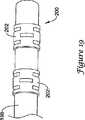
図19はここで考慮される微細加工されたハイポチューブの実施例を示す。図19において、カテーテル198の末端部200が示される。カテーテル198は血管内カテーテルであり、1つ以上のマーカバンド202を備える。マーカバンド202は図1乃至5に関して上述したような微細加工されたハイポチューブの部分である点に特徴を有する。微細加工されたハイポチューブをマーカバンド202として使用することにより付加的な可撓性が得られる。マーカバンド202は好適な放射線不透過性を備えた材料、例えば金、白金、パラジウム、タンタル、タングステン合金等から形成可能である。 FIG. 19 shows an example of a micromachined hypotube considered here. In FIG. 19, the
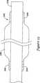
図20は図1乃至5を参照して上述したような微細加工されたハイポチューブの別例を示す。図20は末端部208を有するバルーンカテーテル204の末端部206の長手方向における部分断面図である。バルーンカテーテル204は長尺状をなすシャフト210及び長尺状をなすシャフト上に設けられるバルーン212を含む。1つ以上の圧縮リング214がバルーン212の基端側において長尺状をなすシャフト210内に設けられる。圧縮リング214は図1乃至5に関して上述したような微細加工されたハイポチューブの部分であることに特徴を有する。微細加工されたハイポチューブを圧縮リング214として使用することにより更なる可撓性を得られる。 FIG. 20 shows another example of a micromachined hypotube as described above with reference to FIGS. FIG. 20 is a partial cross-sectional view in the longitudinal direction of the
実施例において、長尺状をなすシャフト210は非常に薄手の側壁部を有し、可撓性及び形状に関して有効である。しかしながら、長尺状をなすシャフト210が有する側壁部が薄すぎる場合に、例えばバルーン212を完全に収縮させるために長尺状をなすシャフト210の内部に真空を作用させると長尺状をなすシャフト210はそれ自体が崩壊する危険性を有する。従って、圧縮リング214は長尺状をなすシャフト210がそれ自体崩壊するのを防止することを補助する。 In an embodiment, the
図21は図1乃至5に関して上述したような微細加工されたハイポチューブの使用の別例を示す。図21はバルーンカテーテル216を示す長手方向における部分断面図である。バルーンカテーテル216は末端部218を有する。バルーンカテーテル216は末端部218に向かって延びる外側シース220、及び末端部218に向かって延びる部分と非延伸部分とを有する内側アセンブリ222を含む。バルーン224は外側シース220上に設けられる。 FIG. 21 shows another example of the use of a micromachined hypotube as described above with respect to FIGS. FIG. 21 is a partial cross-sectional view in the longitudinal direction showing the balloon catheter 216. Balloon catheter 216 has a
内側アセンブリ222はガイドワイヤ管腔226及び膨張管腔228を画定する高分子ライナー224を含む。微細加工されたハイポチューブ230は上述したものと類似するが、ガイドワイヤ管腔226から末端側に延び、バルーンカテーテル216の末端部218に向かって延びる。微細加工されたハイポチューブ230は少なくとも1つのマーカバンド234を収容するよう構成される少なくとも1つの切り欠き232を備える。少なくとも1つのマーカバンド234は周知の構成からなってもよい。図19に示すように実施例において、少なくとも1つのマーカバンド234が微細加工されたハイポチューブの一部であってもよい。
図22,23は実施例において微細加工技術が高分子アセンブリに適用されることを示す。特に、図22はシャフト238に固定されるバルーン236を示す。バルーン236及びシャフト238は好適な材料から形成可能であり、周知の工程により構成可能である。バルーン236は基端側胴部240及び末端側胴部242を備える。実施例において、バルーン236は基端側胴部240及び末端側胴部242をシャフト238に接着することによりシャフト238に固定可能である。 22 and 23 show that the microfabrication technique is applied to the polymer assembly in the embodiment. In particular, FIG. 22 shows a
好適な取付方法により基端側胴部240及び末端側胴部242をシャフト238に固定するが、基端側胴部240及び末端側胴部242にて材料の厚みが大きくなるため可撓性の問題が引き起こされる。従って、図23に示すように可撓性を高めるために一連のカット244が基端側胴部240内に設けられてもよく、一連のカット246が末端側胴部242内に設けられてもよい。一連のカット244及び一連のカット246はいかなる好適な技術を使用して形成されてもよい。実施例において、これらのカット244及び246は図1乃至5を参照して上述した微細加工されたハイポチューブを形成するために使用された微細加工技術を使用して形成されてもよい。 The proximal
図24乃至27はここで開示される微細加工されたハイポチューブの考えられた使用の別の実施例を示す。この実施例において、外側シャフトを内側シャフトに対して少なくとも若干自由に移動させるが、必要な場合に外側シャフトを内側シャフトに対して固定可能にすることに対する要求がある。 FIGS. 24-27 illustrate another example of a contemplated use of the microfabricated hypotube disclosed herein. In this embodiment, the outer shaft is moved at least somewhat freely with respect to the inner shaft, but there is a need to be able to fix the outer shaft to the inner shaft if necessary.
図24は内側シャフト250の上方において使用される外側シャフト248を示す。外側シャフト248は末端部252を有する。図示のように、外側シャフト248は微細加工されたハイポチューブであるが、内側シャフト250はカテーテルシャフトやガイドワイヤであってもよい。 FIG. 24 shows the
実施例において、外側シャフト248及び内側シャフト250の両者はここで開示されるような微細加工されたハイポチューブであってもよい。
基端部256及び末端部258を有する折りたたみ式ケージ254は外側シャフト248の末端部252に隣接する内側シャフト250の上方にて使用される。折りたたみ式ケージ254の基端部256は外側シャフト248の末端部252に固定可能であるが、折りたたみ式ケージ254の末端部258は内側シャフト250上に位置する固定点260(又は複数の固定点260)に固定可能である。実施例において、折りたたみ式ケージ254は外側シャフト248及び内側シャフト250のそれぞれに溶接されるか半田付けされてもよい。In an embodiment, both
A
折りたたみ式ケージ254はステンレス鋼やニチノールのような好適な材料からなる多数のワイヤ262から形成可能である。同様に、外側シャフト248及び内側シャフト250もステンレス鋼やニチノールから形成可能である。 The
図示のように、外側シャフト248は内側シャフト250の外径より若干大きい内径を有する。従って、外側シャフト248は内側シャフト250に対して限定された運動が可能である。図25は外側シャフト248が内側シャフト250に対する位置にどのように固定されるかを示す。 As shown, the
図25において、外側シャフト248は回動方向を示す矢印264によって示されるように内側シャフト250に対して回動される。外側シャフト248が内側シャフト250に対して回動すると、各ワイヤ262が捻られるため折りたたみ式ケージ254は堅固に締まる。外側シャフト248が一定の角度を回動する場合に同一の角度における付加的な回転により内側シャフト250は外側シャフト248と共に回動する。 In FIG. 25, the
図26,27は別の固定機構を使用することを除いて類似の基本原理を示す。図26において、折りたたみ式ケージ254はポリマースリーブ266に代えられる。ポリマースリーブ266は基端部268及び末端部270を有する。ポリマースリーブ266は電気活性ポリマーから形成可能である。基端部268は外側シャフト248の末端部252に固定されるが、末端部270は内側シャフト250上に位置する固定点260に固定される。 Figures 26 and 27 show a similar basic principle, except that another locking mechanism is used. In FIG. 26, the
図示のように、外側シャフト248は内側シャフト250の外径より若干大きい内径を有する。従って、外側シャフト248は内側シャフト250に対して限定された運動が可能である。内側シャフト250は外側シャフト248に対して若干回動するか、外側シャフト248に対して末端側に、或いは基端側に移動してもよい。図27は外側シャフト248が内側シャフト250に対する位置にどのように固定されるかを示す。 As shown, the
図27において電流がポリマースリーブ266に作用され、これによりポリマースリーブ266は内側シャフト250上に収縮される。従って、外側シャフト248及び内側シャフト250間の回動が規制される。実施例において、電流は外側シャフト248を介してポリマースリーブ266に流される。 In FIG. 27, an electric current is applied to the
図28乃至30はここで開示される微細加工されたハイポチューブの使用の別例を示す。図28は例えばカテーテルとして使用可能なアセンブリ272を示す。アセンブリ272は内部276を有する微細加工されたハイポチューブ274を含む。高分子ライナー278が内部276内に設けられる。図示の実施例において、高分子ライナー278は管腔280を画定し、3つのローブ282を備える。実施例において、3つのローブ282は内部276内において高分子ライナー278、ひいては管腔280を中心に位置させるように構成される。別例において、高分子ライナー278は4つ以上のローブ282を含んでもよい。 FIGS. 28-30 illustrate another example of the use of the microfabricated hypotube disclosed herein. FIG. 28 shows an
図29は例えばカテーテルとして使用可能なアセンブリ284を示す。アセンブリは内部276を有する微細加工されたハイポチューブ274を含む。高分子ライナー286が内部276内に設けられる。高分子ライナー286は第1の管腔288及び第2の管腔290を画定し、卵形の断面を有する。実施例において卵形の断面により、高分子ライナー286を内部276内の中心に位置させることが補助される。 FIG. 29 shows an
図30は例えばカテーテルとして使用可能なアセンブリ292を示す。アセンブリは内部276を有する微細加工されたハイポチューブ274を含む。高分子ライナー294が内部276内に設けられる。高分子ライナー294は管腔296を画定し多角形の断面を有する。実施例において多角形の断面により内部276内において高分子ライナー294を中心に位置させることが補助される。図示の実施例において高分子ライナー294は六面の断面を有する。実施例において、高分子ライナー294は四面、五面、七面、或いは八面もの断面を有してもよい。 FIG. 30 shows an
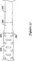
図31及び32は図1乃至5に関して上述したものと同様の微細加工されたハイポチューブの別例を示す。図31及び32は末端部304を画定する末端領域302を有するカテーテル300の一部を示す。カテーテル300は図1乃至5に示す微細加工されたハイポチューブに関して上述したように構成される微細加工されたハイポチューブ306を含む。微細加工されたハイポチューブ306は多数のスロット308を含んでもよい。実施例において全ての微細加工されたハイポチューブ306はスロット308を含むが、別例において可撓性の要件により一部のみがスロット308を含んでもよい。 31 and 32 show another example of a micromachined hypotube similar to that described above with respect to FIGS. FIGS. 31 and 32 illustrate a portion of a
ハイポチューブ管腔310は微細加工されたハイポチューブ306を通過してその末端部304に向かって延びる。膨張可能バルーン312はカテーテル300の末端領域302の周囲に設けられる。外側シース314は膨張可能バルーン312の基端側に設けられ、膨張可能バルーン312によって覆われていない末端領域302の少なくとも一部を覆ってもよい。従って、ハイポチューブ管腔310は膨張可能バルーン312を膨張及び収縮させるために使用可能である。膨張可能バルーン312及び外側シース314は上述したものと同様に好適な高分子材料から形成可能である。図示のように外側シース314は膨張可能バルーン312に隣接するが、外側シース314は膨張可能バルーン312の一部と重合し、或いは別例において膨張可能バルーン312の一部は外側シース314の一部と重合してもよいものと考えられる。 The
実施例においてハイポチューブ310はガイドワイヤ(図示しない)を収容可能な寸法に形成されてもよい。固定されたワイヤ構造体において、ハイポチューブ管腔310の末端部はハイポチューブ管腔310の内部をシールするための栓、或いはその他の構造体を含むものと考えられる。オーバーザワイヤ構造体において、ハイポチューブ管腔310はシール構造体(図示しない)を含んでもよい。シール構造体はガイドワイヤがシール構造体を通過して、少なくとも密封されるように調整される。 In embodiments, the
例えば図32に示すように実施例において、カテーテル300はラピッドエクスチェンジ型に構成可能である。本実施例において、カテーテル300は基端側ガイドワイヤポート316、末端側ガイドワイヤポート318、及び基端側ガイドワイヤポート316から末端側ガイドワイヤポート318に向かって延びるガイドワイヤ管腔320を含む。図32にガイドワイヤ管腔320を点線で示す。 For example, as shown in FIG. 32, in the embodiment, the
実施例においてここで開示される装置の一部や全ては潤滑性コーティングを含んでもよい。潤滑性コーティングは、操作性を向上させ、病変部を通過する能力を高める。
好適な潤滑性ポリマーは当技術分野において周知であり、ポリアリーレンオキサイド、ポリビニルピロリドン、ポリビニルアルコール、ハイドロキシアルキルセルロース誘導体、アルギン、糖類、カプロラクトン等の親水性ポリマーや、これらの混合物や組み合わせを含む。親水性ポリマーは、他の親水性ポリマーとブレンドするか、調合量の水不溶性化合物(ポリマーを含む)とブレンドして、好適な潤滑性、結合性、溶解性を備えたコーティングを生成してもよい。実施例において、個々で開示される装置の部分は親水性ポリマーや登録商標名TEFLONとして周知のポリテトラフルオロエチレン(PTFE)のようなフッ素重合体によりコーティングされてもよい。In some embodiments, some or all of the devices disclosed herein may include a lubricious coating. The lubricious coating improves operability and increases the ability to pass through the lesion.
Suitable lubricious polymers are well known in the art and include hydrophilic polymers such as polyarylene oxide, polyvinyl pyrrolidone, polyvinyl alcohol, hydroxyalkyl cellulose derivatives, algins, sugars, caprolactone, and mixtures and combinations thereof. Hydrophilic polymers can be blended with other hydrophilic polymers or blended with a blended amount of water-insoluble compounds (including polymers) to produce a coating with suitable lubricity, binding, and solubility. Good. In embodiments, the parts of the device disclosed individually may be coated with a hydrophilic polymer or a fluoropolymer such as polytetrafluoroethylene (PTFE), well known under the trade name TEFLON.
本願に開示されている事項は、多くの点において、単に例示的なものであるといえる。構成の詳細に変更を加えることは可能であり、特に、形状、寸法、工程の順序については、本発明の範囲を逸脱することなく変更可能である。本発明の範囲は、当然ながら、請求項に記載された文言において定義される。 In many respects, the subject matter disclosed in this application can be considered as illustrative only. It is possible to change the details of the configuration, and in particular, it is possible to change the shape, dimensions, and the order of steps without departing from the scope of the present invention. The scope of the invention is, of course, defined in the language recited in the claims.
Claims (16)
Translated fromJapanese末端部及び基端部を有する長尺状をなす管と、長尺状をなす管は末端領域から基端領域に向かって延びることと、長尺状をなす管は同長尺状をなす管に沿って設けられた複数のスロットを有することと、スロットは長尺状をなす管の外周面を周方向に延びることと、各スロットは、第1の部分、第2の部分、及びこれらの間の頂点を含むことと、該第1の部分および第2の部分は、周方向に対して傾斜するように該頂点において相互に角度をなすことと、
長尺状をなす管内に設けられる高分子二重管腔ライナーとを備えることと、
各スロットは、隣接するスロットと周方向にずれることとを特徴とするカテーテル。A catheter having a distal region and a proximal region,
An elongated tube having a distal end and a proximal end, an elongated tube extending from the distal region toward the proximal region, and an elongated tube having the same elongated shape Having a plurality of slots provided along the circumferential direction, the slots extending in the circumferential direction on the outer peripheral surface of the elongated tube, and each slot comprising a first portion, a second portion, and Including a vertex in between, thefirst portion and the second portion being angled with respect to each other at the verticesso as to be inclined with respect to a circumferential direction;
A polymer double lumen liner provided in a long tube;
A catheter, wherein each slot is circumferentially offset from an adjacent slot.
末端領域から基端領域に向かって延びる長尺状をなす金属管と、長尺状をなす金属管は同長尺状をなす金属管に沿って設けられる複数のスロットを備えることと、スロットは長尺状をなす金属管の外周面を周方向に延びることと、各スロットは、第1の部分、第2の部分、及びこれらの間の頂点を含むことと、該第1の部分および第2の部分は、周方向に対して傾斜するように該頂点において相互に角度をなすことと、
長尺状をなす金属管の周囲に設けられる高分子スリーブと、
長尺状をなす金属管内に設けられる高分子二重管腔ライナーとを備えることと、
各スロットは、隣接するスロットと周方向にずれることとを特徴とするカテーテル。A catheter having a distal region and a proximal region,
An elongated metal tube extending from the distal region toward the proximal region, the elongated metal tube comprising a plurality of slots provided along the elongated metal tube, and the slot Extending the outer circumferential surface of the elongated metal tube in the circumferential direction, each slot including a first portion, a second portion, and an apex therebetween, thefirst portion and the first portion The two parts are angled relative to each other at the apex so as to be inclined with respect to the circumferential direction;
A polymer sleeve provided around a long metal tube;
Comprising a polymer double-lumen liner provided in a long metal tube;
A catheter, wherein each slot is circumferentially offset from an adjacent slot.
Applications Claiming Priority (3)
| Application Number | Priority Date | Filing Date | Title |
|---|---|---|---|
| US11/301,195US8292827B2 (en) | 2005-12-12 | 2005-12-12 | Micromachined medical devices |
| US11/301,195 | 2005-12-12 | ||
| PCT/US2006/045284WO2007070235A2 (en) | 2005-12-12 | 2006-11-22 | Micromachined medical devices |
Publications (3)
| Publication Number | Publication Date |
|---|---|
| JP2009519103A JP2009519103A (en) | 2009-05-14 |
| JP2009519103A5 JP2009519103A5 (en) | 2010-01-14 |
| JP5202328B2true JP5202328B2 (en) | 2013-06-05 |
Family
ID=38140379
Family Applications (1)
| Application Number | Title | Priority Date | Filing Date |
|---|---|---|---|
| JP2008545617AExpired - Fee RelatedJP5202328B2 (en) | 2005-12-12 | 2006-11-22 | Microfabricated catheter |
Country Status (6)
| Country | Link |
|---|---|
| US (2) | US8292827B2 (en) |
| EP (1) | EP1968678B1 (en) |
| JP (1) | JP5202328B2 (en) |
| AT (1) | ATE518559T1 (en) |
| CA (1) | CA2633048C (en) |
| WO (1) | WO2007070235A2 (en) |
Cited By (1)
| Publication number | Priority date | Publication date | Assignee | Title |
|---|---|---|---|---|
| US11523924B2 (en) | 2015-04-28 | 2022-12-13 | Cook Medical Technologies Llc | Medical cannulae, delivery systems and methods |
Families Citing this family (113)
| Publication number | Priority date | Publication date | Assignee | Title |
|---|---|---|---|---|
| WO2008088766A1 (en) | 2002-03-22 | 2008-07-24 | Cordis Corporation | Rapid-exchange balloon catheter shaft and method |
| US8292827B2 (en) | 2005-12-12 | 2012-10-23 | Boston Scientific Scimed, Inc. | Micromachined medical devices |
| US20070208405A1 (en)* | 2006-03-06 | 2007-09-06 | Boston Scientific Scimed, Inc. | Stent delivery catheter |
| US9232959B2 (en) | 2007-01-02 | 2016-01-12 | Aquabeam, Llc | Multi fluid tissue resection methods and devices |
| US12290277B2 (en) | 2007-01-02 | 2025-05-06 | Aquabeam, Llc | Tissue resection with pressure sensing |
| US11660420B2 (en) | 2018-09-17 | 2023-05-30 | Seigla Medical, Inc. | Catheters and related devices and methods of manufacture |
| JP2009000389A (en)* | 2007-06-22 | 2009-01-08 | Kaneka Corp | Flexible slit marker and catheter having the same |
| US8066703B2 (en)* | 2007-10-08 | 2011-11-29 | Boston Scientific Scimed, Inc. | Sphincterotome with improved orientation |
| US8460213B2 (en)* | 2008-01-03 | 2013-06-11 | Boston Scientific Scimed, Inc. | Cut tubular members for a medical device and methods for making and using the same |
| ES2769535T3 (en) | 2008-03-06 | 2020-06-26 | Aquabeam Llc | Tissue ablation and cauterization with optical energy carried in a fluid stream |
| US9788790B2 (en) | 2009-05-28 | 2017-10-17 | Avinger, Inc. | Optical coherence tomography for biological imaging |
| US20100069882A1 (en)* | 2008-09-18 | 2010-03-18 | Boston Scientific Scimed, Inc. | Medical device with preferential bending |
| US11406791B2 (en) | 2009-04-03 | 2022-08-09 | Scientia Vascular, Inc. | Micro-fabricated guidewire devices having varying diameters |
| WO2010077692A2 (en) | 2008-12-08 | 2010-07-08 | Scientia Vascular Llc | Micro-cutting machine for forming cuts in products |
| US10363389B2 (en)* | 2009-04-03 | 2019-07-30 | Scientia Vascular, Llc | Micro-fabricated guidewire devices having varying diameters |
| US12220538B2 (en) | 2008-12-08 | 2025-02-11 | Scientia Vascular, Inc. | Micro-fabricated intravascular devices having varying diameters |
| AU2010205892A1 (en)* | 2009-01-15 | 2011-07-21 | Cathrx Ltd | Steerable stylet |
| US9011511B2 (en)* | 2009-02-20 | 2015-04-21 | Boston Scientific Scimed, Inc. | Balloon catheter |
| EP2398547A1 (en)* | 2009-02-20 | 2011-12-28 | Boston Scientific Scimed, Inc. | Torqueable balloon catheter |
| US8057430B2 (en) | 2009-02-20 | 2011-11-15 | Boston Scientific Scimed, Inc. | Catheter with skived tubular member |
| US9067332B2 (en)* | 2009-04-03 | 2015-06-30 | Scientia Vascular, Llc | Micro-fabricated catheter devices formed with hybrid materials |
| US9950137B2 (en)* | 2009-04-03 | 2018-04-24 | Scientia Vascular, Llc | Micro-fabricated guidewire devices formed with hybrid materials |
| US9616195B2 (en)* | 2009-04-03 | 2017-04-11 | Scientia Vascular, Llc | Micro-fabricated catheter devices having varying diameters |
| US9067333B2 (en)* | 2009-04-03 | 2015-06-30 | Scientia Vascular, Llc | Micro-fabricated guidewire devices having elastomeric fill compositions |
| US9254123B2 (en) | 2009-04-29 | 2016-02-09 | Hansen Medical, Inc. | Flexible and steerable elongate instruments with shape control and support elements |
| US10743780B2 (en)* | 2010-05-25 | 2020-08-18 | Miracor Medical Sa | Catheter system and method for occluding a body vessel |
| US20120071752A1 (en) | 2010-09-17 | 2012-03-22 | Sewell Christopher M | User interface and method for operating a robotic medical system |
| WO2012109468A1 (en)* | 2011-02-09 | 2012-08-16 | Boston Scientific Scimed, Inc. | Balloon catheter |
| US8821478B2 (en)* | 2011-03-04 | 2014-09-02 | Boston Scientific Scimed, Inc. | Catheter with variable stiffness |
| ES2807348T3 (en)* | 2011-03-07 | 2021-02-22 | Stryker Corp | Balloon catheter and support shaft for it |
| US20130030363A1 (en) | 2011-07-29 | 2013-01-31 | Hansen Medical, Inc. | Systems and methods utilizing shape sensing fibers |
| EP2768568B1 (en) | 2011-10-18 | 2020-05-06 | Boston Scientific Scimed, Inc. | Integrated crossing balloon catheter |
| WO2013067180A1 (en)* | 2011-11-04 | 2013-05-10 | Boston Scientific Scimed, Inc. | Catheter including a bare metal hypotube |
| US9504604B2 (en) | 2011-12-16 | 2016-11-29 | Auris Surgical Robotics, Inc. | Lithotripsy eye treatment |
| EP3351196A1 (en) | 2012-02-29 | 2018-07-25 | Procept Biorobotics Corporation | Automated image-guided tissue resection and treatment |
| US10383765B2 (en) | 2012-04-24 | 2019-08-20 | Auris Health, Inc. | Apparatus and method for a global coordinate system for use in robotic surgery |
| US8684953B2 (en)* | 2012-05-13 | 2014-04-01 | Ozca Engineering Solutions Ltd. | Steering tool |
| DE102012010687B4 (en)* | 2012-05-30 | 2021-08-19 | ADMEDES GmbH | A method for producing a body implant, an assembly comprising a guide wire and a body implant, and a medical instrument |
| US9066828B2 (en) | 2012-06-15 | 2015-06-30 | Trivascular, Inc. | Endovascular delivery system with flexible and torqueable hypotube |
| US9332998B2 (en) | 2012-08-13 | 2016-05-10 | Covidien Lp | Apparatus and methods for clot disruption and evacuation |
| US9332999B2 (en) | 2012-08-13 | 2016-05-10 | Covidien Lp | Apparatus and methods for clot disruption and evacuation |
| US10080873B2 (en) | 2012-12-31 | 2018-09-25 | Clearstream Technologies Limited | Radiopaque balloon catheter and guidewire to facilitate alignment |
| RU2669472C2 (en) | 2012-12-31 | 2018-10-11 | Клиарстрим Текнолоджис Лимитед | Radiopaque conductor for catheter positioning |
| US10231867B2 (en) | 2013-01-18 | 2019-03-19 | Auris Health, Inc. | Method, apparatus and system for a water jet |
| CN103961785A (en)* | 2013-01-31 | 2014-08-06 | 朝日英达科株式会社 | Slitted pipe and guide wire using the same |
| JP2015066163A (en)* | 2013-09-30 | 2015-04-13 | 朝日インテック株式会社 | Slit pipe and guide wire using the slit pipe |
| US10080576B2 (en)* | 2013-03-08 | 2018-09-25 | Auris Health, Inc. | Method, apparatus, and a system for facilitating bending of an instrument in a surgical or medical robotic environment |
| US9867635B2 (en) | 2013-03-08 | 2018-01-16 | Auris Surgical Robotics, Inc. | Method, apparatus and system for a water jet |
| US10149720B2 (en)* | 2013-03-08 | 2018-12-11 | Auris Health, Inc. | Method, apparatus, and a system for facilitating bending of an instrument in a surgical or medical robotic environment |
| US10376672B2 (en) | 2013-03-15 | 2019-08-13 | Auris Health, Inc. | Catheter insertion system and method of fabrication |
| WO2014201165A1 (en) | 2013-06-11 | 2014-12-18 | Auris Surgical Robotics, Inc. | System for robotic assisted cataract surgery |
| US10426661B2 (en) | 2013-08-13 | 2019-10-01 | Auris Health, Inc. | Method and apparatus for laser assisted cataract surgery |
| US9737373B2 (en) | 2013-10-24 | 2017-08-22 | Auris Surgical Robotics, Inc. | Instrument device manipulator and surgical drape |
| EP3060157B1 (en) | 2013-10-24 | 2019-12-11 | Auris Health, Inc. | System for robotic-assisted endolumenal surgery |
| CA2946324C (en) | 2014-05-02 | 2023-03-21 | Intellimedical Technologies Pty Ltd | Elongate steerable devices for insertion into a subject's body |
| US9744335B2 (en) | 2014-07-01 | 2017-08-29 | Auris Surgical Robotics, Inc. | Apparatuses and methods for monitoring tendons of steerable catheters |
| US9788910B2 (en) | 2014-07-01 | 2017-10-17 | Auris Surgical Robotics, Inc. | Instrument-mounted tension sensing mechanism for robotically-driven medical instruments |
| US10792464B2 (en) | 2014-07-01 | 2020-10-06 | Auris Health, Inc. | Tool and method for using surgical endoscope with spiral lumens |
| US9561083B2 (en) | 2014-07-01 | 2017-02-07 | Auris Surgical Robotics, Inc. | Articulating flexible endoscopic tool with roll capabilities |
| USD743007S1 (en)* | 2014-12-01 | 2015-11-10 | Asahi Intecc Co., Ltd. | Slitted pipe |
| US11819636B2 (en) | 2015-03-30 | 2023-11-21 | Auris Health, Inc. | Endoscope pull wire electrical circuit |
| US10675057B2 (en) | 2015-04-28 | 2020-06-09 | Cook Medical Technologies Llc | Variable stiffness cannulae and associated delivery systems and methods |
| WO2016191415A1 (en) | 2015-05-26 | 2016-12-01 | Vascular Solutions, Inc. | Guidewire fixation |
| CN108348133B (en) | 2015-09-09 | 2020-11-13 | 奥瑞斯健康公司 | Instrument Manipulators for Surgical Robotic Systems |
| US10799672B2 (en)* | 2015-10-16 | 2020-10-13 | Covidien Lp | Catheter body structural support member including a polymer hypotube |
| US10252024B2 (en) | 2016-04-05 | 2019-04-09 | Stryker Corporation | Medical devices and methods of manufacturing same |
| US11344327B2 (en) | 2016-06-03 | 2022-05-31 | Avinger, Inc. | Catheter device with detachable distal end |
| US10555756B2 (en) | 2016-06-27 | 2020-02-11 | Cook Medical Technologies Llc | Medical devices having coaxial cannulae |
| US9918705B2 (en) | 2016-07-07 | 2018-03-20 | Brian Giles | Medical devices with distal control |
| US10391274B2 (en) | 2016-07-07 | 2019-08-27 | Brian Giles | Medical device with distal torque control |
| US11052228B2 (en) | 2016-07-18 | 2021-07-06 | Scientia Vascular, Llc | Guidewire devices having shapeable tips and bypass cuts |
| US11207502B2 (en)* | 2016-07-18 | 2021-12-28 | Scientia Vascular, Llc | Guidewire devices having shapeable tips and bypass cuts |
| US10646689B2 (en) | 2016-07-29 | 2020-05-12 | Cephea Valve Technologies, Inc. | Mechanical interlock for catheters |
| US10646340B2 (en) | 2016-08-19 | 2020-05-12 | Edwards Lifesciences Corporation | Steerable delivery system for replacement mitral valve |
| US10463439B2 (en) | 2016-08-26 | 2019-11-05 | Auris Health, Inc. | Steerable catheter with shaft load distributions |
| US10821268B2 (en) | 2016-09-14 | 2020-11-03 | Scientia Vascular, Llc | Integrated coil vascular devices |
| AU2017373953B2 (en) | 2016-12-08 | 2023-05-11 | Abiomed, Inc. | Overmold technique for peel-away introducer design |
| US10751514B2 (en) | 2016-12-09 | 2020-08-25 | Teleflex Life Sciences Limited | Guide extension catheter |
| US11452541B2 (en) | 2016-12-22 | 2022-09-27 | Scientia Vascular, Inc. | Intravascular device having a selectively deflectable tip |
| US20200093472A1 (en)* | 2017-03-24 | 2020-03-26 | Robert J Cottone | Systems and methods for tissue displacement |
| KR102576296B1 (en) | 2017-05-17 | 2023-09-08 | 아우리스 헬스, 인코포레이티드 | Interchangeable working channels |
| ES2966345T3 (en) | 2017-05-26 | 2024-04-22 | Scientia Vascular Inc | Microfabricated medical device with a non-helical cutting arrangement |
| WO2019116322A1 (en) | 2017-12-14 | 2019-06-20 | Meacor Sal | Helical anchor driving system |
| WO2019118792A1 (en)* | 2017-12-15 | 2019-06-20 | Boston Scientific Scimed, Inc. | Medical device for accessing and/or treating the neural vasculature |
| JP2021511943A (en)* | 2018-01-29 | 2021-05-13 | トランジット サイエンティフィック,エルエルシー | Elongated medical device with flexible reinforced features |
| US10456556B2 (en)* | 2018-02-19 | 2019-10-29 | Bendit Technologies Ltd. | Steering tool with enhanced flexibility and trackability |
| US11305095B2 (en) | 2018-02-22 | 2022-04-19 | Scientia Vascular, Llc | Microfabricated catheter having an intermediate preferred bending section |
| CN117017505A (en) | 2018-03-28 | 2023-11-10 | 奥瑞斯健康公司 | Composite instrument and robotic system |
| US12167867B2 (en) | 2018-04-19 | 2024-12-17 | Avinger, Inc. | Occlusion-crossing devices |
| KR20200071749A (en)* | 2018-05-09 | 2020-06-19 | 아사히 인텍크 가부시키가이샤 | Medical tube |
| ES2991910T3 (en) | 2018-05-16 | 2024-12-05 | Abiomed Inc | Removable cover set |
| WO2020033318A1 (en) | 2018-08-07 | 2020-02-13 | Auris Health, Inc. | Combining strain-based shape sensing with catheter control |
| CN112804933B (en) | 2018-09-26 | 2024-10-18 | 奥瑞斯健康公司 | Articulating medical device |
| US11524142B2 (en) | 2018-11-27 | 2022-12-13 | Teleflex Life Sciences Limited | Guide extension catheter |
| EP3897802A4 (en) | 2018-12-19 | 2022-10-05 | Teleflex Life Sciences Limited | Guide extension catheter |
| WO2020139973A1 (en) | 2018-12-28 | 2020-07-02 | Auris Health, Inc. | Medical instrument with articulable segment |
| WO2020146035A1 (en) | 2019-01-07 | 2020-07-16 | Teleflex Life Sciences Limited | Guide extension catheter |
| US12011555B2 (en) | 2019-01-15 | 2024-06-18 | Scientia Vascular, Inc. | Guidewire with core centering mechanism |
| WO2020154314A1 (en)* | 2019-01-21 | 2020-07-30 | Transit Scientific, LLC | Hypotube catheters |
| US11617627B2 (en) | 2019-03-29 | 2023-04-04 | Auris Health, Inc. | Systems and methods for optical strain sensing in medical instruments |
| EP4013324B1 (en) | 2019-08-14 | 2025-09-24 | Biocompatibles UK Limited | Dual stage cryocooler |
| WO2021028883A1 (en) | 2019-08-15 | 2021-02-18 | Auris Health, Inc. | Medical device having multiple bending sections |
| US11478609B2 (en)* | 2019-09-26 | 2022-10-25 | Biosense Webster (Israel) Ltd. | Bendable guidewire |
| CN114727839A (en)* | 2019-11-18 | 2022-07-08 | 瑟卡科学有限公司 | Device port for epicardial ablation with inflatable balloon |
| CN114901188A (en) | 2019-12-31 | 2022-08-12 | 奥瑞斯健康公司 | Dynamic pulley system |
| US12178975B2 (en) | 2020-01-23 | 2024-12-31 | Scientia Vascular, Inc. | Guidewire having enlarged, micro-fabricated distal section |
| US12343485B2 (en) | 2020-01-23 | 2025-07-01 | Scientia Vascular, Inc. | High torque guidewire device |
| US11642178B2 (en) | 2020-02-07 | 2023-05-09 | Centerline Biomedical, Inc. | Guidewire |
| EP4552680A3 (en)* | 2020-03-11 | 2025-07-16 | Stryker Corporation | Slotted catheter with fillers |
| US12296112B2 (en) | 2020-10-05 | 2025-05-13 | Scientia Vascular, Inc. | Microfabricated catheter devices with high axial strength |
| US20240424254A1 (en)* | 2023-05-25 | 2024-12-26 | Boston Scientific Scimed, Inc. | Delivery systems for cryoablation device |
| CN117752919B (en)* | 2024-02-20 | 2024-11-19 | 北京深瑞达医疗科技有限公司 | Guide wire |
| CN117982777B (en)* | 2024-04-03 | 2024-06-14 | 万漉医疗科技(江苏)有限公司 | Guide wire system with sacculus |
Family Cites Families (103)
| Publication number | Priority date | Publication date | Assignee | Title |
|---|---|---|---|---|
| US4547193A (en) | 1984-04-05 | 1985-10-15 | Angiomedics Incorporated | Catheter having embedded multi-apertured film |
| US4580551A (en) | 1984-11-02 | 1986-04-08 | Warner-Lambert Technologies, Inc. | Flexible plastic tube for endoscopes and the like |
| US4795439A (en) | 1986-06-06 | 1989-01-03 | Edward Weck Incorporated | Spiral multi-lumen catheter |
| US4753238A (en) | 1987-01-06 | 1988-06-28 | Advanced Cardiovascular Systems, Inc. | Proximal manifold and adapter |
| US4998923A (en) | 1988-08-11 | 1991-03-12 | Advanced Cardiovascular Systems, Inc. | Steerable dilatation catheter |
| US5507751A (en) | 1988-11-09 | 1996-04-16 | Cook Pacemaker Corporation | Locally flexible dilator sheath |
| US5095915A (en) | 1990-03-19 | 1992-03-17 | Target Therapeutics | Guidewire with flexible distal tip |
| US5238004A (en) | 1990-04-10 | 1993-08-24 | Boston Scientific Corporation | High elongation linear elastic guidewire |
| US5106455A (en) | 1991-01-28 | 1992-04-21 | Sarcos Group | Method and apparatus for fabrication of micro-structures using non-planar, exposure beam lithography |
| US5228441A (en) | 1991-02-15 | 1993-07-20 | Lundquist Ingemar H | Torquable catheter and method |
| US5329923A (en) | 1991-02-15 | 1994-07-19 | Lundquist Ingemar H | Torquable catheter |
| AU660444B2 (en) | 1991-02-15 | 1995-06-29 | Ingemar H. Lundquist | Torquable catheter and method |
| US5315996A (en) | 1991-02-15 | 1994-05-31 | Lundquist Ingemar H | Torquable catheter and method |
| CA2117088A1 (en) | 1991-09-05 | 1993-03-18 | David R. Holmes | Flexible tubular device for use in medical applications |
| US5741429A (en) | 1991-09-05 | 1998-04-21 | Cardia Catheter Company | Flexible tubular device for use in medical applications |
| US5328472A (en) | 1992-07-27 | 1994-07-12 | Medtronic, Inc. | Catheter with flexible side port entry |
| US5437288A (en) | 1992-09-04 | 1995-08-01 | Mayo Foundation For Medical Education And Research | Flexible catheter guidewire |
| US5334145A (en) | 1992-09-16 | 1994-08-02 | Lundquist Ingemar H | Torquable catheter |
| US5372144A (en) | 1992-12-01 | 1994-12-13 | Scimed Life Systems, Inc. | Navigability improved guidewire construction and method of using same |
| JP3345147B2 (en) | 1993-01-26 | 2002-11-18 | テルモ株式会社 | Vasodilators and catheters |
| DE69432379T2 (en) | 1993-01-26 | 2004-02-05 | Terumo K.K. | Vascular dilatation device and catheter |
| US6576008B2 (en) | 1993-02-19 | 2003-06-10 | Scimed Life Systems, Inc. | Methods and device for inserting and withdrawing a two piece stent across a constricting anatomic structure |
| US5772609A (en) | 1993-05-11 | 1998-06-30 | Target Therapeutics, Inc. | Guidewire with variable flexibility due to polymeric coatings |
| US5989280A (en) | 1993-10-22 | 1999-11-23 | Scimed Lifesystems, Inc | Stent delivery apparatus and method |
| EP0749333A1 (en)* | 1994-03-10 | 1996-12-27 | Schneider (Usa) Inc. | Catheter having shaft of varying stiffness |
| US5902290A (en) | 1994-03-14 | 1999-05-11 | Advanced Cardiovascular Systems, Inc. | Catheter providing intraluminal access |
| US6139510A (en) | 1994-05-11 | 2000-10-31 | Target Therapeutics Inc. | Super elastic alloy guidewire |
| US5569197A (en) | 1994-12-21 | 1996-10-29 | Schneider (Usa) Inc | Drug delivery guidewire |
| US5797856A (en) | 1995-01-05 | 1998-08-25 | Cardiometrics, Inc. | Intravascular guide wire and method |
| JPH08257128A (en)* | 1995-03-24 | 1996-10-08 | Piolax Inc | Medical tube |
| US5788707A (en) | 1995-06-07 | 1998-08-04 | Scimed Life Systems, Inc. | Pull back sleeve system with compression resistant inner shaft |
| US6287315B1 (en) | 1995-10-30 | 2001-09-11 | World Medical Manufacturing Corporation | Apparatus for delivering an endoluminal prosthesis |
| US20030069522A1 (en) | 1995-12-07 | 2003-04-10 | Jacobsen Stephen J. | Slotted medical device |
| US5833632A (en) | 1995-12-07 | 1998-11-10 | Sarcos, Inc. | Hollow guide wire apparatus catheters |
| EP0778039A1 (en) | 1995-12-07 | 1997-06-11 | Sarcos, Inc. | Catheter guide wire |
| US6428489B1 (en) | 1995-12-07 | 2002-08-06 | Precision Vascular Systems, Inc. | Guidewire system |
| US6004279A (en) | 1996-01-16 | 1999-12-21 | Boston Scientific Corporation | Medical guidewire |
| US5695506A (en) | 1996-02-06 | 1997-12-09 | Devices For Vascular Intervention | Catheter device with a flexible housing |
| US5730726A (en)* | 1996-03-04 | 1998-03-24 | Klingenstein; Ralph James | Apparatus and method for removing fecal impaction |
| US6533805B1 (en) | 1996-04-01 | 2003-03-18 | General Surgical Innovations, Inc. | Prosthesis and method for deployment within a body lumen |
| US6629981B2 (en) | 2000-07-06 | 2003-10-07 | Endocare, Inc. | Stent delivery system |
| US6017319A (en) | 1996-05-24 | 2000-01-25 | Precision Vascular Systems, Inc. | Hybrid tubular guide wire for catheters |
| US6440088B1 (en) | 1996-05-24 | 2002-08-27 | Precision Vascular Systems, Inc. | Hybrid catheter guide wire apparatus and method |
| US6077295A (en) | 1996-07-15 | 2000-06-20 | Advanced Cardiovascular Systems, Inc. | Self-expanding stent delivery system |
| JP3968444B2 (en) | 1996-08-23 | 2007-08-29 | ボストン サイエンティフィック サイムド,インコーポレイテッド | Stent delivery mechanism with stent fixation device |
| US6123712A (en) | 1996-08-23 | 2000-09-26 | Scimed Life Systems, Inc. | Balloon catheter with stent securement means |
| US6391032B2 (en) | 1996-08-23 | 2002-05-21 | Scimed Life Systems, Inc. | Stent delivery system having stent securement means |
| US6007543A (en) | 1996-08-23 | 1999-12-28 | Scimed Life Systems, Inc. | Stent delivery system with stent securement means |
| US6077273A (en) | 1996-08-23 | 2000-06-20 | Scimed Life Systems, Inc. | Catheter support for stent delivery |
| US6014919A (en) | 1996-09-16 | 2000-01-18 | Precision Vascular Systems, Inc. | Method and apparatus for forming cuts in catheters, guidewires, and the like |
| US5772669A (en) | 1996-09-27 | 1998-06-30 | Scimed Life Systems, Inc. | Stent deployment catheter with retractable sheath |
| US6001068A (en) | 1996-10-22 | 1999-12-14 | Terumo Kabushiki Kaisha | Guide wire having tubular connector with helical slits |
| DE19721703A1 (en) | 1997-05-23 | 1998-11-26 | Angiomed Ag | Catheter system with high kink resistance |
| US5928260A (en)* | 1997-07-10 | 1999-07-27 | Scimed Life Systems, Inc. | Removable occlusion system for aneurysm neck |
| EP0937481A1 (en) | 1998-02-19 | 1999-08-25 | Precision Vascular Systems, Inc. | Catheter or guidewire with varying flexibility |
| US6174327B1 (en) | 1998-02-27 | 2001-01-16 | Scimed Life Systems, Inc. | Stent deployment apparatus and method |
| DE59812219D1 (en) | 1998-03-04 | 2004-12-09 | Schneider Europ Gmbh Buelach | Device for inserting an endoprosthesis into a catheter shaft |
| EP1067882A1 (en) | 1998-03-31 | 2001-01-17 | Salviac Limited | A delivery catheter |
| IE980241A1 (en) | 1998-04-02 | 1999-10-20 | Salviac Ltd | Delivery catheter with split sheath |
| US6004310A (en) | 1998-06-17 | 1999-12-21 | Target Therapeutics, Inc. | Multilumen catheter shaft with reinforcement |
| US6048339A (en) | 1998-06-29 | 2000-04-11 | Endius Incorporated | Flexible surgical instruments with suction |
| US6093194A (en) | 1998-09-14 | 2000-07-25 | Endocare, Inc. | Insertion device for stents and methods for use |
| WO2000027462A1 (en) | 1998-11-06 | 2000-05-18 | The Furukawa Electric Co., Ltd. | NiTi-TYPE MEDICAL GUIDE WIRE AND METHOD OF PRODUCING THE SAME |
| US6102932A (en) | 1998-12-15 | 2000-08-15 | Micrus Corporation | Intravascular device push wire delivery system |
| US6254609B1 (en) | 1999-01-11 | 2001-07-03 | Scimed Life Systems, Inc. | Self-expanding stent delivery system with two sheaths |
| WO2000066211A1 (en) | 1999-04-30 | 2000-11-09 | Usaminanotechnology, Inc. | Catheter and guide wire |
| US6241758B1 (en) | 1999-05-28 | 2001-06-05 | Advanced Cardiovascular Systems, Inc. | Self-expanding stent delivery system and method of use |
| US6168617B1 (en) | 1999-06-14 | 2001-01-02 | Scimed Life Systems, Inc. | Stent delivery system |
| US6398802B1 (en) | 1999-06-21 | 2002-06-04 | Scimed Life Systems, Inc. | Low profile delivery system for stent and graft deployment |
| US6287291B1 (en) | 1999-11-09 | 2001-09-11 | Advanced Cardiovascular Systems, Inc. | Protective sheath for catheters |
| US6702802B1 (en) | 1999-11-10 | 2004-03-09 | Endovascular Technologies, Inc. | Catheters with improved transition |
| US6579246B2 (en) | 1999-12-22 | 2003-06-17 | Sarcos, Lc | Coronary guidewire system |
| US6602280B2 (en) | 2000-02-02 | 2003-08-05 | Trivascular, Inc. | Delivery system and method for expandable intracorporeal device |
| WO2001060432A1 (en) | 2000-02-15 | 2001-08-23 | Eva Corporation | Delivery catheter assembly and method of securing a surgical component to a vessel during a surgical procedure |
| US6743219B1 (en) | 2000-08-02 | 2004-06-01 | Cordis Corporation | Delivery apparatus for a self-expanding stent |
| US6562064B1 (en) | 2000-10-27 | 2003-05-13 | Vascular Architects, Inc. | Placement catheter assembly |
| US6428566B1 (en) | 2000-10-31 | 2002-08-06 | Advanced Cardiovascular Systems, Inc. | Flexible hoop and link sheath for a stent delivery system |
| US6436090B1 (en) | 2000-12-21 | 2002-08-20 | Advanced Cardiovascular Systems, Inc. | Multi lumen catheter shaft |
| US6592568B2 (en) | 2001-01-11 | 2003-07-15 | Scimed Life Systems, Inc. | Balloon assembly for stent delivery catheter |
| US6623491B2 (en) | 2001-01-18 | 2003-09-23 | Ev3 Peripheral, Inc. | Stent delivery system with spacer member |
| US6699274B2 (en) | 2001-01-22 | 2004-03-02 | Scimed Life Systems, Inc. | Stent delivery system and method of manufacturing same |
| US6743210B2 (en) | 2001-02-15 | 2004-06-01 | Scimed Life Systems, Inc. | Stent delivery catheter positioning device |
| US6592549B2 (en) | 2001-03-14 | 2003-07-15 | Scimed Life Systems, Inc. | Rapid exchange stent delivery system and associated components |
| US6660031B2 (en) | 2001-04-11 | 2003-12-09 | Scimed Life Systems, Inc. | Multi-length delivery system |
| US20030009208A1 (en) | 2001-07-05 | 2003-01-09 | Precision Vascular Systems, Inc. | Torqueable soft tip medical device and method of usage |
| US6726714B2 (en) | 2001-08-09 | 2004-04-27 | Scimed Life Systems, Inc. | Stent delivery system |
| US6918882B2 (en) | 2001-10-05 | 2005-07-19 | Scimed Life Systems, Inc. | Guidewire with stiffness blending connection |
| US6652508B2 (en) | 2001-11-09 | 2003-11-25 | Scimed Life Systems, Inc. | Intravascular microcatheter having hypotube proximal shaft with transition |
| JP2003164528A (en)* | 2001-11-29 | 2003-06-10 | Nippon Sherwood Medical Industries Ltd | Balloon catheter |
| JP2003175110A (en) | 2001-12-07 | 2003-06-24 | Kanegafuchi Chem Ind Co Ltd | Balloon catheter and method for manufacturing the same |
| US7294124B2 (en) | 2001-12-28 | 2007-11-13 | Boston Scientific Scimed, Inc. | Hypotube with improved strain relief |
| DE60334122D1 (en) | 2002-07-25 | 2010-10-21 | Boston Scient Ltd | MEDICAL DEVICE FOR NAVIGATING THROUGH ANATOMY |
| US20040167441A1 (en) | 2003-02-26 | 2004-08-26 | Reynolds Brian R. | Composite medical device |
| US20040167437A1 (en) | 2003-02-26 | 2004-08-26 | Sharrow James S. | Articulating intracorporal medical device |
| US7142903B2 (en) | 2003-03-12 | 2006-11-28 | Biosense Webster, Inc. | Catheter with contractable mapping assembly |
| US7276062B2 (en) | 2003-03-12 | 2007-10-02 | Biosence Webster, Inc. | Deflectable catheter with hinge |
| US7001369B2 (en) | 2003-03-27 | 2006-02-21 | Scimed Life Systems, Inc. | Medical device |
| US7785273B2 (en) | 2003-09-22 | 2010-08-31 | Boston Scientific Scimed, Inc. | Guidewire with reinforcing member |
| US7744619B2 (en) | 2004-02-24 | 2010-06-29 | Boston Scientific Scimed, Inc. | Rotatable catheter assembly |
| US20050209582A1 (en)* | 2004-03-22 | 2005-09-22 | Medtronic Vascular, Inc. | Multi-lumen catheter system |
| US20050234499A1 (en) | 2004-04-19 | 2005-10-20 | Scimed Life Systems, Inc. | Multi-lumen balloon catheter including manifold |
| US20070083132A1 (en) | 2005-10-11 | 2007-04-12 | Sharrow James S | Medical device coil |
| US8292827B2 (en) | 2005-12-12 | 2012-10-23 | Boston Scientific Scimed, Inc. | Micromachined medical devices |
- 2005
- 2005-12-12USUS11/301,195patent/US8292827B2/enactiveActive
- 2006
- 2006-11-22EPEP06838313Apatent/EP1968678B1/enactiveActive
- 2006-11-22CACA2633048Apatent/CA2633048C/ennot_activeExpired - Fee Related
- 2006-11-22JPJP2008545617Apatent/JP5202328B2/ennot_activeExpired - Fee Related
- 2006-11-22WOPCT/US2006/045284patent/WO2007070235A2/enactiveApplication Filing
- 2006-11-22ATAT06838313Tpatent/ATE518559T1/ennot_activeIP Right Cessation
- 2012
- 2012-10-23USUS13/658,309patent/US20130072904A1/ennot_activeAbandoned
Cited By (2)
| Publication number | Priority date | Publication date | Assignee | Title |
|---|---|---|---|---|
| US11523924B2 (en) | 2015-04-28 | 2022-12-13 | Cook Medical Technologies Llc | Medical cannulae, delivery systems and methods |
| US12376979B2 (en) | 2015-04-28 | 2025-08-05 | Cook Medical Technologies Llc | Medical cannulae, delivery systems and methods |
Also Published As
| Publication number | Publication date |
|---|---|
| US20070135763A1 (en) | 2007-06-14 |
| WO2007070235A3 (en) | 2008-05-02 |
| WO2007070235A2 (en) | 2007-06-21 |
| US20130072904A1 (en) | 2013-03-21 |
| CA2633048A1 (en) | 2007-06-21 |
| JP2009519103A (en) | 2009-05-14 |
| EP1968678B1 (en) | 2011-08-03 |
| US8292827B2 (en) | 2012-10-23 |
| CA2633048C (en) | 2014-08-12 |
| EP1968678A2 (en) | 2008-09-17 |
| ATE518559T1 (en) | 2011-08-15 |
Similar Documents
| Publication | Publication Date | Title |
|---|---|---|
| JP5202328B2 (en) | Microfabricated catheter | |
| EP2185232B1 (en) | Microfabricated catheter with improved bonding structure | |
| ES2807348T3 (en) | Balloon catheter and support shaft for it | |
| JP5450432B2 (en) | Long medical device with moldable tip | |
| US8535243B2 (en) | Medical devices and tapered tubular members for use in medical devices | |
| US8376961B2 (en) | Micromachined composite guidewire structure with anisotropic bending properties | |
| JP5643510B2 (en) | Catheter shaft design | |
| US9227037B2 (en) | Cut tubular members for a medical device and methods for making and using the same | |
| US8137293B2 (en) | Guidewires including a porous nickel-titanium alloy | |
| JP4808617B2 (en) | Telescopic restriction catheter shaft | |
| US7914467B2 (en) | Tubular member having tapered transition for use in a medical device | |
| EP2183015B1 (en) | Guidewires and methods for manufacturing guidewires | |
| JP6582127B2 (en) | Pressure detection guide wire | |
| JP6412247B2 (en) | Medical device for measuring blood pressure | |
| JP6946265B2 (en) | Medical device | |
| WO2013080729A1 (en) | Atherectomy catheter | |
| US20230166079A1 (en) | Steerable elongate medical device | |
| US20250195035A1 (en) | Intravascular imaging catheter |
Legal Events
| Date | Code | Title | Description |
|---|---|---|---|
| A521 | Request for written amendment filed | Free format text:JAPANESE INTERMEDIATE CODE: A523 Effective date:20091120 | |
| A621 | Written request for application examination | Free format text:JAPANESE INTERMEDIATE CODE: A621 Effective date:20091120 | |
| A131 | Notification of reasons for refusal | Free format text:JAPANESE INTERMEDIATE CODE: A131 Effective date:20111206 | |
| A977 | Report on retrieval | Free format text:JAPANESE INTERMEDIATE CODE: A971007 Effective date:20111208 | |
| RD04 | Notification of resignation of power of attorney | Free format text:JAPANESE INTERMEDIATE CODE: A7424 Effective date:20120112 | |
| A521 | Request for written amendment filed | Free format text:JAPANESE INTERMEDIATE CODE: A523 Effective date:20120306 | |
| A131 | Notification of reasons for refusal | Free format text:JAPANESE INTERMEDIATE CODE: A131 Effective date:20120918 | |
| A601 | Written request for extension of time | Free format text:JAPANESE INTERMEDIATE CODE: A601 Effective date:20121218 | |
| A521 | Request for written amendment filed | Free format text:JAPANESE INTERMEDIATE CODE: A523 Effective date:20121226 | |
| A602 | Written permission of extension of time | Free format text:JAPANESE INTERMEDIATE CODE: A602 Effective date:20121226 | |
| TRDD | Decision of grant or rejection written | ||
| A01 | Written decision to grant a patent or to grant a registration (utility model) | Free format text:JAPANESE INTERMEDIATE CODE: A01 Effective date:20130129 | |
| A61 | First payment of annual fees (during grant procedure) | Free format text:JAPANESE INTERMEDIATE CODE: A61 Effective date:20130212 | |
| R150 | Certificate of patent or registration of utility model | Free format text:JAPANESE INTERMEDIATE CODE: R150 Ref document number:5202328 Country of ref document:JP Free format text:JAPANESE INTERMEDIATE CODE: R150 | |
| FPAY | Renewal fee payment (event date is renewal date of database) | Free format text:PAYMENT UNTIL: 20160222 Year of fee payment:3 | |
| R250 | Receipt of annual fees | Free format text:JAPANESE INTERMEDIATE CODE: R250 | |
| R250 | Receipt of annual fees | Free format text:JAPANESE INTERMEDIATE CODE: R250 | |
| R250 | Receipt of annual fees | Free format text:JAPANESE INTERMEDIATE CODE: R250 | |
| R250 | Receipt of annual fees | Free format text:JAPANESE INTERMEDIATE CODE: R250 | |
| R250 | Receipt of annual fees | Free format text:JAPANESE INTERMEDIATE CODE: R250 | |
| R250 | Receipt of annual fees | Free format text:JAPANESE INTERMEDIATE CODE: R250 | |
| R250 | Receipt of annual fees | Free format text:JAPANESE INTERMEDIATE CODE: R250 | |
| R250 | Receipt of annual fees | Free format text:JAPANESE INTERMEDIATE CODE: R250 | |
| LAPS | Cancellation because of no payment of annual fees |