JP5199246B2 - Clock display with translucent cover using light source - Google Patents
Clock display with translucent cover using light sourceDownload PDFInfo
- Publication number
- JP5199246B2 JP5199246B2JP2009512265AJP2009512265AJP5199246B2JP 5199246 B2JP5199246 B2JP 5199246B2JP 2009512265 AJP2009512265 AJP 2009512265AJP 2009512265 AJP2009512265 AJP 2009512265AJP 5199246 B2JP5199246 B2JP 5199246B2
- Authority
- JP
- Japan
- Prior art keywords
- display
- cover
- light emitting
- conduit
- light
- Prior art date
- Legal status (The legal status is an assumption and is not a legal conclusion. Google has not performed a legal analysis and makes no representation as to the accuracy of the status listed.)
- Active
Links
Images


Classifications
- G—PHYSICS
- G04—HOROLOGY
- G04G—ELECTRONIC TIME-PIECES
- G04G17/00—Structural details; Housings
- G04G17/02—Component assemblies
- G04G17/04—Mounting of electronic components
- G04G17/045—Mounting of the display
- G—PHYSICS
- G04—HOROLOGY
- G04G—ELECTRONIC TIME-PIECES
- G04G17/00—Structural details; Housings
- G04G17/08—Housings
- G—PHYSICS
- G04—HOROLOGY
- G04G—ELECTRONIC TIME-PIECES
- G04G21/00—Input or output devices integrated in time-pieces
- G—PHYSICS
- G09—EDUCATION; CRYPTOGRAPHY; DISPLAY; ADVERTISING; SEALS
- G09F—DISPLAYING; ADVERTISING; SIGNS; LABELS OR NAME-PLATES; SEALS
- G09F13/00—Illuminated signs; Luminous advertising
- G09F13/20—Illuminated signs; Luminous advertising with luminescent surfaces or parts
- G09F13/22—Illuminated signs; Luminous advertising with luminescent surfaces or parts electroluminescent
- G—PHYSICS
- G09—EDUCATION; CRYPTOGRAPHY; DISPLAY; ADVERTISING; SEALS
- G09F—DISPLAYING; ADVERTISING; SIGNS; LABELS OR NAME-PLATES; SEALS
- G09F9/00—Indicating arrangements for variable information in which the information is built-up on a support by selection or combination of individual elements
- G09F9/30—Indicating arrangements for variable information in which the information is built-up on a support by selection or combination of individual elements in which the desired character or characters are formed by combining individual elements
- G09F9/33—Indicating arrangements for variable information in which the information is built-up on a support by selection or combination of individual elements in which the desired character or characters are formed by combining individual elements being semiconductor devices, e.g. diodes
Landscapes
- Physics & Mathematics (AREA)
- General Physics & Mathematics (AREA)
- Engineering & Computer Science (AREA)
- Theoretical Computer Science (AREA)
- Illuminated Signs And Luminous Advertising (AREA)
- Electric Clocks (AREA)
- Devices For Indicating Variable Information By Combining Individual Elements (AREA)
- Light Guides In General And Applications Therefor (AREA)
Description
Translated fromJapanese関連出願の相互参照
本出願は、参照により本明細書に組み入れられその一部となる、2006年5月22日に出願された米国特許仮出願第60/802,637号に対する優先権を主張する。CROSS-REFERENCE TO RELATED APPLICATIONS This application is a part incorporated herein by reference, claims priority to U.S. Provisional Patent Application No. 60 / 802,637, filed on May 22, 2006.
発明の分野
本発明は電子装置用などのディスプレイに関する。本発明の種々の実施例は特に時計ディスプレイに有用である。The present invention relates to displays for electronic devices and the like. Various embodiments of the present invention are particularly useful for clock displays.
背景
従来のディスプレイおよびディスプレイアセンブリは、いくつかの不都合と限界を有している。独特でかつ既存の時計と異なる美しい外見と機能性を有する時計および他の電子ディスプレイアセンブリに対する消費者からの需要が存在する。加えて、既存の時計および他の電子ディスプレイアセンブリの多くは、十分な耐水性を提供していない。BACKGROUND Conventional displays and display assemblies have several disadvantages and limitations. There is a consumer demand for watches and other electronic display assemblies that are unique and have a beautiful appearance and functionality that is different from existing watches. In addition, many existing watches and other electronic display assemblies do not provide sufficient water resistance.
本発明は、上述の問題および他の問題を解決するために、ならびにこの型の従来のディスプレイアセンブリが備えていない利点および外観を備えさせるために、提供される。本発明の特性および利点の十分な議論は、添付の図面を参照して進められる以下の詳細な説明に委ねられる。 The present invention is provided to solve the above and other problems and to provide the advantages and appearance that this type of conventional display assembly does not provide. A full discussion of the features and advantages of the present invention is deferred to the following detailed description, which proceeds with reference to the accompanying drawings.
発明の概要
本発明の種々の局面は、人間が判読可能なしるしを表面に選択的に表示するディスプレイと該ディスプレイ上に配置されたカバーとを含むディスプレイアセンブリに関する。カバーはディスプレイの全表面上で概ね均一な表面を有する。ディスプレイアセンブリは不活性状態と活性状態との間で制御可能である。不活性状態ではしるしは該カバーを通しては見えないが、活性状態ではしるしは該カバーを通して見える。SUMMARY OF THE INVENTION Various aspects of the invention relate to a display assembly that includes a display that selectively displays on a surface human-readable indicia and a cover disposed on the display. The cover has a generally uniform surface over the entire surface of the display. The display assembly is controllable between an inactive state and an active state. In the inactive state no indicia is visible through the cover, but in the active state the indicia is visible through the cover.
ある局面によると、カバーは、カバーの隣接部分の厚さよりも実質的に小さな厚さを有する薄い部分を有している。薄い部分は、ディスプレイの表面上に位置付けられて、アセンブリが活性状態の時にしるしを見えるようにする。 According to one aspect, the cover has a thin portion having a thickness that is substantially less than the thickness of the adjacent portion of the cover. The thin portion is positioned on the surface of the display so that the indicia can be seen when the assembly is active.
別の局面によると、カバーは透光性部分と不透明部分とを有する。透光性部分は、ディスプレイの表面上に位置付けられて、アセンブリが活性状態の時にしるしを見えるようにする。 According to another aspect, the cover has a translucent portion and an opaque portion. The translucent portion is positioned on the surface of the display so that the indicia can be seen when the assembly is active.
更なる局面によると、ディスプレイは1個またはそれ以上の発光デバイスを有し、しるしを作り出す。カバーは1個またはそれ以上の導管を有し、各導管は各発光デバイスと実質的に整列している。 According to a further aspect, the display has one or more light emitting devices to create indicia. The cover has one or more conduits, each conduit being substantially aligned with each light emitting device.
更なる局面によると、ディスプレイはコンピューター構成部品を含む電子ディスプレイモジュールに一体化される。均一な表面は、ボタンをその上に画定する輪郭を有する。各ボタンはディスプレイモジュールに動作可能に連結してコンピューター構成部品と相互作用する。ある局面では、コンピューター構成部品は、別個の電子デバイスと通信しかつ同電子デバイスを制御するように構成されている。 According to a further aspect, the display is integrated into an electronic display module that includes computer components. The uniform surface has a contour that defines a button thereon. Each button is operably connected to the display module to interact with the computer components. In certain aspects, the computer component is configured to communicate with and control a separate electronic device.
本発明の他の局面は、上述のディスプレイアセンブリと共に使用するようなバンドに関する。ある局面では、バンドは、ディスプレイに動作可能に接続されたストラップとディスプレイモジュールを受け入れる空洞を有するホルダーと上述のカバーとを備える。ストラップはアセンブリを使用者の体に取り付けるように適合している。ストラップはカバーおよび/またはホルダーと同じ材料で作られてもよく、かつストラップ、カバー、およびホルダーは単一の一体型部品から形成されてもよい。
[本発明101]
人間が判読可能なしるしをその表面に選択的に表示するディスプレイと、
該ディスプレイの全表面上に配置され、かつ該ディスプレイの全表面上に均一な表面を有するカバーと
を備える、ディスプレイアセンブリ。
[本発明102]
カバーが薄い部分を有し、該薄い部分がカバーの隣接部分の厚さよりも実質的に小さな厚さを有し、該薄い部分がディスプレイの表面上に位置付けられている、
本発明101のディスプレイアセンブリ。
[本発明103]
ディスプレイが、しるしを作り出す複数のLEDを有し、カバーが複数の導管を有し、各導管が各LEDと実質的に整列している、
本発明101のディスプレイアセンブリ。
[本発明104]
カバーが厚さを有し、各導管がカバーの該厚さの一部分を貫いて延びる、
本発明103のディスプレイアセンブリ。
[本発明105]
ディスプレイの表面とカバーとの間に位置付けられた剛体のシェルを更に備えるディスプレイアセンブリであって、
該シェルが、それを貫いて延びる複数の導管を備え、
LEDの一つから発せられる光がシェルの対応する導管とカバーの導管とを通って進んでカバーを通して見えるように、カバーの各導管がシェルの導管の一つおよびLEDの一つと実質的に整列している、
本発明103のディスプレイアセンブリ。
[本発明106]
カバーが透光性部分と不透明部分とを有し、該透光性部分がディスプレイの表面上に位置付けられている、
本発明101のディスプレイアセンブリ。
[本発明107]
ディスプレイが、コンピューター構成部品を含む電子ディスプレイモジュールに一体化している、
本発明101のディスプレイアセンブリ。
[本発明108]
均一な表面が、ボタンをその上に画定する輪郭を有し、各ボタンがディスプレイモジュールに動作可能に連結してコンピューター構成部品と相互作用する、
本発明107のディスプレイアセンブリ。
[本発明109]
コンピューター構成部品が、別個の電子デバイスと通信しかつ同電子デバイスを制御するように構成されている、
本発明107のディスプレイアセンブリ。
[本発明110]
人間が判読可能なしるしをその表面に選択的に表示するディスプレイと、
該ディスプレイの表面上に配置されたカバーと
を備え、
該ディスプレイの表面が該カバーを通して見えない不活性状態と、しるしが該カバーを通して見える活性状態との間で制御可能である、
ディスプレイアセンブリ。
[本発明111]
カバーが薄い部分を有し、該薄い部分がカバーの隣接部分の厚さより実質的に小さな厚さを有し、該薄い部分がディスプレイの表面上に配置される、
本発明110のディスプレイアセンブリ。
[本発明112]
アセンブリが不活性状態の時に、薄い部分がディスプレイの見え方(vision)を不明瞭にし、アセンブリが活性状態の時に、ディスプレイが薄い部分を通して見える光を発し、それによりしるしが薄い部分を通して見える、
本発明111のディスプレイアセンブリ。
[本発明113]
ディスプレイが、しるしを作り出す複数のLEDを有し、カバーが複数の導管を有し、各導管が各LEDと実質的に整列し、アセンブリが活性状態の時に、光が各LEDから発せられて対応する導管に進みカバーを通して見える、
本発明110のディスプレイアセンブリ。
[本発明114]
カバーが厚さを有し、各導管がカバーの該厚さの一部分を貫いて延びる、
本発明113のディスプレイアセンブリ。
[本発明115]
ディスプレイの表面とカバーとの間に位置付けられた剛体のシェルとを更に備えるディスプレイアセンブリであって、
該シェルがそれを貫いて延びる複数の導管を備え、
LEDの一つから発せられる光がシェルの対応する導管とカバーの導管とを通って進んでカバーを通して見えるように、カバーの各導管がシェルの導管の一つおよびLEDの一つと実質的に整列している、
本発明113のディスプレイアセンブリ。
[本発明116]
カバーが透光性部分と不透明部分とを有し、該透光性部分がディスプレイの表面上に位置付けられている、
本発明110のディスプレイアセンブリ。
[本発明117]
アセンブリが不活性状態の時に、透光性部分がディスプレイの見え方を不明瞭にし、アセンブリが活性状態の時に、ディスプレイが透光性部分を通して見える光を発し、それによりしるしが該透光性部分を通して見える、
本発明116のディスプレイアセンブリ。
[本発明118]
ディスプレイが、コンピューター構成部品を含む電子ディスプレイモジュールに一体化している、
本発明110のディスプレイアセンブリ。
[本発明119]
コンピューター構成部品が、別個の電子デバイスと通信しかつ同電子デバイスを制御するように構成されている、
本発明118のディスプレイアセンブリ。
[本発明120]
人間が判読可能なしるしをその表面に選択的に表示するディスプレイと、
該ディスプレイの表面上に配置された、或る材料から作られたカバーと、
該ディスプレイおよび該カバーに動作可能に接続されたストラップと
を備えるディスプレイアセンブリであって、
該カバーと同じ材料で作られた該ストラップが、該アセンブリを使用者の体に取り付けるように適合している、
ディスプレイアセンブリ。
[本発明121]
カバーおよびストラップが可撓性のポリマー材料から作られている、
本発明120のディスプレイアセンブリ。
[本発明122]
カバーおよびストラップの材料が、恒久的な変形または破壊を伴うことなく90度より大きい角度に曲がるのに十分な可撓性を有する、
本発明121のディスプレイアセンブリ。
[本発明123]
カバーおよびストラップがポリウレタン材料から作られている、
本発明120のディスプレイアセンブリ。
[本発明124]
カバーおよびストラップが単一の一体型部品から形成されている、
本発明120のディスプレイアセンブリ。
[本発明125]
内部に画定された空洞を有するホルダーであって、空洞が、人間が判読可能なしるしをその表面に選択的に表示するディスプレイを有する電子ディスプレイモジュールを受け入れるように適合している、ホルダーと、
該ホルダーを使用者の体に取り付けるように適合したストラップと
を備え、
該ストラップおよび該ホルダーが単一の一体型部品から形成されている、
使用者の体に取り付けるように適合したバンド。
[本発明126]
ホルダーが薄い部分を有し、該薄い部分がホルダーの隣接部分の厚さより実質的に小さな厚さを有し、該薄い部分が、ディスプレイモジュールが空洞に受け入れられる時に、ディスプレイの表面上に位置づけられるように適合している、
本発明125のバンド。
[本発明127]
薄い部分が、カバーの厚さの一部分を貫いて延びる複数の導管を備える、
本発明126のバンド。
[本発明128]
ホルダーが透光性部分と半透明部分とを有し、該透光性部分が、ディスプレイモジュールが空洞に受け入れられる時に、ディスプレイの表面上に位置付けられるように適合している、
本発明125のバンド。
[本発明129]
空洞が、ホルダーの一部分がディスプレイの表面を覆うようにディスプレイモジュールを受け入れるように適合している、
本発明125のバンド。
[本発明130]
ホルダーが、ボタンをその上に画定する輪郭を有し、各ボタンが、該ディスプレイモジュールと相互作用するように適合している、
本発明129のバンド。
[本発明131]
内部に画定された空洞を有するホルダーであって、空洞が、人間が判読可能なしるしを表面に選択的に表示する電子ディスプレイを有する電子ディスプレイモジュールを受け入れるように適合している、ホルダーと、
該ホルダーを使用者の体に取り付けるように適合したストラップと
を備え、
該ホルダーが、ディスプレイの全表面上に配置されるように適合したカバーを形成し、該カバーがディスプレイの全表面上に均一の表面を有している、
使用者の体に取り付けられるのに適用したバンド。
[本発明132]
カバーが薄い部分を有し、該薄い部分がカバーの隣接部分の厚さより実質的に小さな厚さを有し、該薄い部分が、ディスプレイモジュールが空洞に受け入れられる時に、ディスプレイの表面上に位置づけられるように適合している、
本発明31のバンド。
[本発明133]
薄い部分が、カバーの厚さの一部分を貫いて延びる複数の導管を備える、
本発明132のバンド。
[本発明134]
複数の導管の各々が電子ディスプレイ上の複数のLEDの一つと実質的に整列するように適合している、
本発明133のバンド。
[本発明135]
カバーが透光性部分と半透明部分とを有し、該透光性部分が、ディスプレイモジュールが空洞に受け入れられる時に、ディスプレイの表面上に位置付けられるように適合している、
本発明131のバンド。
[本発明136]
均一な表面が、ボタンをその上に画定する輪郭を有し、各ボタンが、ディスプレイモジュールと相互作用するように適合している、
本発明131のバンド。
[本発明137]
人間が判読可能なしるしをその表面に選択的に表示するディスプレイと、
該ディスプレイの表面上に配置された、可撓性ポリマー材料から作られたカバーと
を備える、ディスプレイアセンブリ。
[本発明138]
カバーの材料が、恒久的な変形または破壊を伴うことなく90度より大きい角度に曲がるのに十分な可撓性を有している、
本発明137のディスプレイアセンブリ。
[本発明139]
カバーがポリウレタン材料から作られている、
本発明137のディスプレイアセンブリ。
[本発明140]
ディスプレイの表面とカバーとの間に位置付けられた剛体のシェルを更に備える、
本発明137のディスプレイアセンブリ。
[本発明141]
複数の発光デバイスを有し、かつ人間が判読可能なしるしをその表面に選択的に表示するように構成された電子ディスプレイと、
該電子ディスプレイを制御するコンピューター構成部品と
を備える、電子ディスプレイモジュールと;
電子ディスプレイモジュールを受け入れるように適合した空洞を内部に画定し、かつディスプレイの全表面上に配置されるように適合したカバーを形成するホルダーであって、該カバーがディスプレイの全表面上に均一な表面を有し、かつ該電子ディスプレイモジュールが、ディスプレイの表面がカバーを通して見えない不活性状態と、しるしがカバーを通して見える活性状態との間で制御可能である、ホルダーと、
カバーの厚さの一部を貫いて延びる複数の導管を有するカバーであって、各導管が各発光デバイスと実質的に整列し、電子ディスプレイモジュールが活性状態の時に、発光デバイスから発せられた光が該導管を通って進んでカバーを通して見える、カバーと、
使用者の体に取り付けるように適合したストラップであって、該ストラップと該ホルダーと該カバーとが、可撓性のポリマー材料の単一の一体型部品で形成されている、ストラップと
を備える、使用者の体に取り付けるように適合したバンドと;
を備える、時計。Another aspect of the invention relates to a band for use with the display assembly described above. In one aspect, the band comprises a strap operably connected to the display, a holder having a cavity for receiving the display module, and the cover described above. The strap is adapted to attach the assembly to the user's body. The strap may be made of the same material as the cover and / or holder, and the strap, cover, and holder may be formed from a single integral part.
[Invention 101]
A display that selectively displays human-readable indicia on its surface;
A display assembly comprising a cover disposed on the entire surface of the display and having a uniform surface on the entire surface of the display.
[Invention 102]
The cover has a thin portion, the thin portion has a thickness substantially less than the thickness of an adjacent portion of the cover, and the thin portion is positioned on the surface of the display;
Display assemblyofthe present invention 101.
[Invention 103]
The display has a plurality of LEDs that create indicia, the cover has a plurality of conduits, and each conduit is substantially aligned with each LED;
Display assemblyofthe present invention 101.
[Invention 104]
The cover has a thickness and each conduit extends through a portion of the thickness of the cover;
Display assemblyofthe present invention 103.
[Invention 105]
A display assembly further comprising a rigid shell positioned between the display surface and the cover, comprising:
The shell comprises a plurality of conduits extending therethrough;
Each conduit of the cover is substantially aligned with one of the shell conduit and one of the LEDs so that the light emitted from one of the LEDs travels through the corresponding conduit of the shell and the conduit of the cover and is visible through the cover. doing,
Display assemblyofthe present invention 103.
[Invention 106]
The cover has a translucent portion and an opaque portion, and the translucent portion is positioned on the surface of the display;
Display assemblyofthe present invention 101.
[Invention 107]
The display is integrated into an electronic display module containing computer components,
Display assemblyofthe present invention 101.
[Invention 108]
The uniform surface has a contour defining buttons thereon, and each button is operably connected to the display module to interact with computer components.
Display assemblyofthe present invention 107.
[Invention 109]
The computer component is configured to communicate with and control a separate electronic device;
Display assemblyofthe present invention 107.
[Invention 110]
A display that selectively displays human-readable indicia on its surface;
A cover disposed on the surface of the display;
Controllable between an inactive state where the surface of the display is not visible through the cover and an active state where an indicia is visible through the cover;
Display assembly.
[Invention 111]
The cover has a thin portion, the thin portion has a thickness substantially less than the thickness of an adjacent portion of the cover, and the thin portion is disposed on the surface of the display;
Display assemblyofthe present invention 110.
[Invention 112]
When the assembly is inactive, the thin part obscures the vision of the display, and when the assembly is active, the display emits light that is visible through the thin part, so that the indicia is visible through the thin part.
Display assemblyofthe present invention 111.
[Invention 113]
The display has multiple LEDs that produce indicia, the cover has multiple conduits, each conduit is substantially aligned with each LED, and light is emitted from each LED to respond when the assembly is active Go to the conduit to see through the cover,
Display assemblyofthe present invention 110.
[Invention 114]
The cover has a thickness and each conduit extends through a portion of the thickness of the cover;
Display assemblyofthe present invention 113.
[Invention 115]
A display assembly further comprising a rigid shell positioned between the display surface and the cover, comprising:
The shell comprises a plurality of conduits extending therethrough;
Each conduit of the cover is substantially aligned with one of the shell conduit and one of the LEDs so that the light emitted from one of the LEDs travels through the corresponding conduit of the shell and the conduit of the cover and is visible through the cover. doing,
Display assemblyofthe present invention 113.
[Invention 116]
The cover has a translucent portion and an opaque portion, and the translucent portion is positioned on the surface of the display;
Display assemblyofthe present invention 110.
[Invention 117]
When the assembly is in an inactive state, the translucent part obscures the appearance of the display, and when the assembly is in the active state, the display emits light that is visible through the translucent part, so that the indicia is the translucent part. Visible through the
Display assemblyofthe present invention 116.
[Invention 118]
The display is integrated into an electronic display module containing computer components,
Display assemblyofthe present invention 110.
[Invention 119]
The computer component is configured to communicate with and control a separate electronic device;
Display assemblyofthe present invention 118.
[Invention 120]
A display that selectively displays human-readable indicia on its surface;
A cover made of a material disposed on the surface of the display;
A display assembly comprising the display and a strap operably connected to the cover, the display assembly comprising:
The strap made of the same material as the cover is adapted to attach the assembly to a user's body;
Display assembly.
[Invention 121]
The cover and strap are made of a flexible polymer material;
Display assemblyofthe present invention 120.
[Invention 122]
The cover and strap material is flexible enough to bend at an angle greater than 90 degrees without permanent deformation or destruction;
Display assemblyofthe present invention 121.
[Invention 123]
The cover and strap are made of polyurethane material,
Display assemblyofthe present invention 120.
[Invention 124]
The cover and strap are formed from a single integral part;
Display assemblyofthe present invention 120.
[Invention 125]
A holder having a cavity defined therein, wherein the cavity is adapted to receive an electronic display module having a display that selectively displays a human-readable indicia on its surface;
A strap adapted to attach the holder to a user's body;
The strap and the holder are formed from a single integral part;
A band adapted to be attached to the user's body.
[Invention 126]
The holder has a thin portion, the thin portion having a thickness substantially less than the thickness of the adjacent portion of the holder, and the thin portion is positioned on the surface of the display when the display module is received in the cavity. Is fit as
125of thepresent invention 125.
[Invention 127]
The thin portion comprises a plurality of conduits extending through a portion of the thickness of the cover;
Bandofthe present invention 126.
[Invention 128]
The holder has a translucent part and a translucent part, the translucent part being adapted to be positioned on the surface of the display when the display module is received in the cavity;
125of thepresent invention 125.
[Invention 129]
The cavity is adapted to receive the display module such that a portion of the holder covers the surface of the display;
125of thepresent invention 125.
[Invention 130]
The holder has a contour defining buttons thereon, each button being adapted to interact with the display module;
Bandofthe present invention 129.
[Invention 131]
A holder having a cavity defined therein, wherein the cavity is adapted to receive an electronic display module having an electronic display that selectively displays on the surface human-readable indicia;
A strap adapted to attach the holder to a user's body;
The holder forms a cover adapted to be disposed on the entire surface of the display, the cover having a uniform surface on the entire surface of the display;
A band applied to the user's body.
[Invention 132]
The cover has a thin portion, the thin portion has a thickness substantially less than the thickness of the adjacent portion of the cover, and the thin portion is positioned on the surface of the display when the display module is received in the cavity. Is fit as
Bandofthe present invention 31.
[Invention 133]
The thin portion comprises a plurality of conduits extending through a portion of the thickness of the cover;
Bandofthe present invention 132.
[Invention 134]
Each of the plurality of conduits is adapted to substantially align with one of the plurality of LEDs on the electronic display;
Bandofthe present invention 133.
[Invention 135]
The cover has a translucent portion and a translucent portion, the translucent portion being adapted to be positioned on the surface of the display when the display module is received in the cavity;
Bandofthe present invention 131.
[Invention 136]
The uniform surface has a contour defining buttons thereon, and each button is adapted to interact with the display module;
Bandofthe present invention 131.
[Invention 137]
A display that selectively displays human-readable indicia on its surface;
A display assembly comprising a cover made of a flexible polymer material disposed on a surface of the display.
[Invention 138]
The cover material is flexible enough to bend at an angle greater than 90 degrees without permanent deformation or breakage,
Display assemblyofthe present invention 137.
[Invention 139]
The cover is made of polyurethane material,
Display assemblyofthe present invention 137.
[Invention 140]
Further comprising a rigid shell positioned between the display surface and the cover;
Display assemblyofthe present invention 137.
[Invention 141]
An electronic display having a plurality of light emitting devices and configured to selectively display a human readable indicia on its surface;
An electronic display module comprising a computer component for controlling the electronic display;
A holder defining a cavity adapted to receive an electronic display module therein and forming a cover adapted to be disposed over the entire surface of the display, the cover being uniform over the entire surface of the display A holder having a surface and the electronic display module is controllable between an inactive state where the surface of the display is not visible through the cover and an active state where the indicia is visible through the cover;
A cover having a plurality of conduits extending through a portion of the thickness of the cover, wherein each conduit is substantially aligned with each light emitting device and light emitted from the light emitting device when the electronic display module is active Is visible through the cover as it travels through the conduit;
A strap adapted to be attached to a user's body, wherein the strap, the holder, and the cover are formed of a single integral piece of flexible polymeric material; A band adapted to be attached to the user's body;
A watch equipped with.
本発明を理解するために、これから添付の図面を参照し例証を用いて説明する。 In order to understand the present invention, it will now be described by way of example with reference to the accompanying drawings.
詳細な説明
本発明は、多くの異なる形の態様を許容可能であるが、本開示は本発明の原理の例示として考えられるべきものであり、本発明の広範な局面を例証した態様に限定するようには意図されていないという理解のもとで、本発明の好ましい態様が図に示されかつ本明細書に詳細に説明されている。DETAILED DESCRIPTION While this invention is susceptible to many different forms of embodiment, this disclosure is to be considered as illustrative of the principles of this invention and is limited to embodiments that illustrate a broad aspect of the invention. With the understanding that this is not intended, the preferred embodiments of the invention are illustrated in the drawings and are described in detail herein.
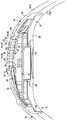
図のまずは図1〜5を参照すると、概してディスプレイモジュール12と使用者の体に取り付けるのに適応したバンド14とを備える電子ディスプレイアセンブリ10が図示されている。ディスプレイモジュール12はその表面24に人間が判読可能なしるし22を選択的に表示するディスプレイ20を備える。図示した態様において、ディスプレイアセンブリ10は腕時計であり、バンド14は、ディスプレイアセンブリ10を使用者の手首または腕に固定するためのストラップ30と締め具またはバックル32とを有している。 Referring initially to FIGS. 1-5, an
図面に示した態様において、ディスプレイモジュール12は電子ディスプレイモジュールであり、かつコンピュータ構成部品を含んでもよい。例えば、アセンブリ10のディスプレイモジュール12は、現在の時間および日付を維持するのに時間間隔をインクリメントしたりストップウォッチ機能および他の機能を実行したりといった時計の諸機能を実行するために、1個または複数のコンピュータ構成部品を含んでもよい。別の態様では、ディスプレイモジュール12は、オーディオファイルを保存し再生するように構成されたコンピュータ構成部品を含んでもよい。更なる態様では、ディスプレイモジュール12は、他の機能を実行するためのコンピュータ構成部品を含んでもよい。加えて、ディスプレイモジュール12は、しるしに加えて他のアウトプットを作り出すように構成されてもよく、有線および/または無線のコミュニケーション構成部品を含むコミュニケーション構成部品を有してもよい。例えばある態様では、ディスプレイモジュール12は、別の電子デバイスと通信しかつ同電子デバイスの制御を行う1個またはそれ以上のコンピュータ構成部品を含む。図1〜6に示すように、いくつかの態様では、アセンブリ10はオーディオプレイヤーを無線で制御するためのボタン43、52を有する。ボタン43、52は以下でより詳細に説明する。これらのボタン43、52にはある機能を与えることが可能であること、およびボタン43、52を押す順序と長さとを含むボタン押し技術に基づき、一つのボタンが多くの機能を有してもよいことが理解されている。更にまた、ディスプレイモジュール12は、靴搭載センサーから受け取る、走る速さおよび距離などのデータを受け取って表示することに関する機能を含むことができる。 In the embodiment shown in the drawings, the
上述したように、ディスプレイモジュール12のディスプレイ20は、例えば、数「2」を表示する、図1に示された数のしるし22などのような、人間が判読可能なしるし22を選択的に表示する表面24を有する。ディスプレイモジュール12が時計に組み込まれる時に、しるし22は、他のしるしに加えて時間および日付のしるしを含んでもよい。ディスプレイ20が、多くの異なる型のしるしを表示するように構成されてもよいこと、および、表示される情報の性質が、表示されるしるしの型に影響を与え得ることが、理解されている。加えて、ディスプレイ20は、しるし22を表示するための多くの異なるデバイスのいずれかを含んでもよい。一つの例示的な態様として、ディスプレイ20は、例えば、動力基板に適用された発光ダイオード(LED)またはエレクトロルミネセント物質などのような、使用者に情報を伝達するしるしを表示するための1個またはそれ以上の発光デバイス26を含む。当然ながら、白熱光または蛍光のような任意の所望の発光デバイスが本発明の代替例で使用可能である。図1〜7に示した態様では、発光デバイス26は、選択的に発光して判読可能なしるし22を形成する35個のLED26を含む。ディスプレイ20は、しるしが見えない不活性状態と、しるしが見える活性状態との間で制御可能である。例えば、図1〜7に示したディスプレイ20において、LEDは活性状態で発光し、不活性状態では発光しない。 As described above, the
図1〜7に示す態様において、バンド14は、ディスプレイモジュール12を保持するためのホルダー34と使用者の体に取り付けるためのストラップ30とを含む。バンド14は、締め付ける目的でストラップ30に取り付けられた締め具またはバックル32もまた含んでもよい。ホルダー34は、ディスプレイモジュール12を受け入れるように設計された空洞36を内部に含んでもよい。一つの例示的な態様において、バンド14はディスプレイ20の表面24上に配置されるカバー40を画定する。図1〜7に示す態様において、カバー40はディスプレイ20の全表面24上に配置され、発光デバイス26だけでなくディスプレイ20がその上に位置付けられている表面全体をも覆っている。カバー40は、従来のディスプレイに共通である不均一な表面よりもむしろ均一な表面42を有するディスプレイを提供する。本明細書で用いられる「均一な」とは、表面42が、表面42の実質的な全体に亘って実質的に一貫した特性を有することを意味している。例えば、図1〜6に示す態様における表面42は、表面42の実質的な全体に亘って視覚的に一貫した特性および組織的に(texturally)一貫した特性を有している。表面42は他のまたは追加の一貫した特性をまた有してもよい。ある態様においては、ホルダー34およびストラップ30は同じ材料から作られており、図1〜7に示す態様においては、ホルダー34およびストラップ30は単一の一体物で作られている。同様に、カバー40およびストラップ30も同じ材料から作ることができ、かつ単一の一体物から作ることができ、カバー40に均一の表面42を提供している。ある態様では、カバー40、ホルダー34、およびストラップ30はポリウレタンまたは別のポリマー材料などの可撓性のポリマー材料から作られている。ある態様では、可撓性の材料は、恒久的な変形または材料の破壊を伴うことなく90度より大きい角度に曲がるのに十分な可撓性を有している。図2および図6に示すように、バンド14は、異なる色のポリウレタンから作られた2層、41Aおよび41Bを有するような、2層の「2段(double-shot)」ポリマーから作られてもよい。カバー40はまた、ゆるやかな曲線の輪郭をディスプレイ20上の表面42に提供している。 In the embodiment shown in FIGS. 1-7, the
図1〜7に示す態様において、ディスプレイ20はカバー40を通して選択的に見える。ディスプレイ20が不活性状態である時に、カバー40が表面24を覆って不明瞭にするので、ディスプレイの表面24はカバー40を通して見えない。ディスプレイ20が活性状態である時、活性な(発光した)LEDがカバー40を通して見え、それによりしるし22がカバー40を通して見える。 In the embodiment shown in FIGS. 1-7, the
一つの例示的な態様において、カバー40は概して不透明であり、かつディスプレイ20上に位置づけられた透光性部分44を有する。この透光性部分44は、ディスプレイ20が不活性状態の時にディスプレイ20を効果的に不明瞭にするが、ディスプレイ20が活性状態の時に発光デバイス26を見えるようにするために光に対して十分に許容的である。別の態様では、カバー40は厚さを有し、ディスプレイ20上に位置づけられた薄い部分46を有する。この薄い部分46は、ディスプレイ20が不活性状態の時にディスプレイ20を効果的に不明瞭にするが、ディスプレイ20が活性状態の時に発光デバイス26を見えるようにするのに十分なほど薄い。図6および図7に示す態様では、薄い部分46はカバー40の隣接部分の厚さより実質的に小さな厚さを有する。 In one exemplary embodiment, the
一つの例示的な態様において、図6と図7で図解するように、カバー40は、カバー40の厚さの一部分を貫いて延び、かつ複数の個別の薄い部分46を作り出す複数の導管48を含む。ある態様では、導管48は、各導管における該カバーの厚さが約0.4mmであるように、カバー40の表面42の近くで延びている。薄い部分46の厚さが小さいので、薄い部分46は透光性となる。各導管48は、ディスプレイ20のLED26の一つと実質的に整列しているので、ディスプレイ20が活性状態の時に各LED26が発する光は対応する導管48を通って進み、カバー40を通して見える。活性の発光デバイス26から導管48とカバー40を通る光線23の通過は、図7に示されている。光をカバー40の表面へより効果的に運ぶまたは注ぎ込むために、導管48は先細りになっていてよい。他の態様では、カバー40が、1個またはそれ以上のより大きい薄いおよび/または透明な部分を有してもよいことが理解されている。例えば、ディスプレイは複数のLEDを有してもよく、単一の薄いおよび/もしくは透明な領域が多数のLEDを囲んでもよく、またはある例では全てのLEDを囲んでもよい。ある態様では、導管48は光をある場所から別の場所に運ぶと同時に、この2つの場所の間の光の拡散および/または減衰を最小化する。図6および図7に示した導管48は中空であるが、本発明の他の態様では、各導管48を充填材または挿入物で満たしてもよい。例えば、導管48は、図8および図9に例示し以下により詳細に説明するように、可撓性の光ファイバーケーブル、ガラス棒、または透明なプラスチックの充填材もしくは挿入物を含んでもよい。更にある態様では、バンド14の全部または一部は、カバー40の全部または一部を含めて、光の通過を可能にするために、透明または透光性の材料から製造される可能性がある。 In one exemplary embodiment, as illustrated in FIGS. 6 and 7, the
図1〜7に示した態様では、カバー40の表面42はその上にいくつかのボタン43を有する。ボタン43は、例えば、ディスプレイモジュール12を制御するおよび/または作動するなどのように、ディスプレイモジュール12と相互作用するように適合する。ボタン43はその上に各ボタン43の機能を示すしるしを備えてもよい。バンド14のホルダー34は更に、カバー40の縁部から下方に延びるサイドフラップ38も備えてもよく、各サイドフラップ38は、以下に説明し図2および図5に示すように、さらなるボタン52へのアクセスを提供する開口39を有する。 In the embodiment shown in FIGS. 1-7, the
図1〜7に示したディスプレイアセンブリ10は、ディスプレイモジュール12とカバー40との間に配置された剛体のシェルまたはケース50を備える。より詳細には、シェル50はディスプレイモジュール12の周りに形成され、更に空洞36に受け入れられてディスプレイモジュール12を空洞36内に保持するのを容易にする。ある態様では、シェル50は、モジュール12を空洞36内に密閉して耐水性を提供するためにバンド14に密閉技術で接続されている。シェル50は更にまた前面部品58と背面部品60とを含んでもよく、これらは協働してディスプレイモジュール12を保持するシェル50を形成する。ある態様では、図5に例示するように、背面部品60は、ディスプレイモジュール12にアクセスし電池64を組み込んだり外したりするための開口62を有する。電池カバー66は、背面部品60に取り付けられ開口62を閉じることができ、ガスケット68は、密閉する目的で開口62またはその周りに位置付け可能である。一つの例示的な態様において、前面部品58はポリカーボネートのようなポリマーから作られ、背面部品60と電池カバー66はステンレス鋼から作られる。他の態様では、シェル50の構成部品は他の材料から作られてもよい。加えて、シェル50のいくつかのまたは全部のプラスチック構成部品は、ポリウレタンの薄い外層を有するポリカーボネートなどのような2層の「2段」ポリマーから作られてもよい。 The
シェル50はその上に、ディスプレイモジュール12と相互作用してディスプレイモジュール12を制御または作動するように適合したボタン52もまた有してもよい。ボタン52はシェル50の凹部55に位置付けられ、バンド14の開口39を通してアクセス可能である。同様に、シェル50は窓56を有し、カバー40のボタン43がディスプレイモジュール12にアクセス可能である。図示した態様では、ボタン52は2層の「2段」ポリマーで形成されている。 The
しるし22がカバー40を通して見えるために、このようなシェル50は、発光デバイス26から発せられた光を不明瞭にしたり妨害したりしてはならない。図5〜7に示すように、シェル50の前面部品58は複数の導管54を有し、各導管54はカバー40の導管48の一つに対応している。従って、図示した態様では、各LED26からの光はシェル50の導管54を通り、カバー40の対応している導管48を通って進み、カバー40を通して見える。導管48、54は、発光デバイス26(例えばLED26)と動作可能に関連する単一の導管を共同で画定すると考えることができ、光は該導管を通って進み、活性状態においてカバー40を通して見えるしるし22を提供する。 Such a
ある態様では、図5〜7に図示するように、これらの導管54は中空である。しかし、導管54は、カバー40の導管48に関して同様に説明したように、挿入物などの材料で満たされてもよいことが理解されている。図8は、透明な充填材157で満たした導管154を有するシェル150のこのようなある態様を図示している。この態様では、充填材157はシェル150の表面と同一平面であって、シェル150上に配置されたカバー(図示せず)内に延びて行かない。加えて、図示した充填材157は相互接続されてシェル150の下の充填材の層153を形成する。図9は、透明な充填材257で満たした導管254を有する、シェル250の別のこのような態様を図示している。この態様では、充填材257は、シェル250上に配置されたカバー240の導管248内に延びて、導管248の少なくとも一部分を満たしている。この構成により光はカバー240の材料内へよりよく局所的に透過できるようになる。この態様では、図示した充填材257は相互接続されてシェル250の下の充填材の層253を形成し、かつ層253は各導管254の下に凹部251を有して各発光デバイス(図示せず)からの光の集まりを改善する。 In some embodiments, these
いくつかの態様では、これらの透明な充填材157、257はプラスチックから作られ、「2段」技術を使って製造される。加えて、いくつかの態様では、充填材157、257は相互接続されない可能性があり、層153、253を形成しない可能性がある。充填材157、257は、図1〜6に示すようにディスプレイアセンブリ10で使用される場合、光透過率を改善し、かつディスプレイモジュール12の電子部品を保護する働きをすることもできる。より詳細には、もしも薄い部分46が壊れたり裂けたりした場合、充填材157、257はディスプレイモジュール12内への異物および/または湿気の侵入を阻止する。 In some embodiments, these
更なる態様においては、前面部品58は、窓56と同様に光がシェル50を通過可能になるように、より大きい窓または他の構造を有してもよい。代替として、発光デバイス26からの光の漏れまたは流出が十分に制御されるならば、シェル50の全体またはその前面部分58は、光がそれを通過できるように透明な材料から成形されてもよい。 In further embodiments, the
本明細書において説明されたディスプレイアセンブリ10の種々の態様は、時計および他の電子デバイスを含む既存のディスプレイアセンブリに優る利点を提供する。例えば、単一部品のバンドおよび固く密閉されたケースは耐水性を提供する。加えて、カバーの均一な表面およびカバーを通してディスプレイを判読できることにより、容易に判読できるディスプレイと感じの良い美的外観が提供される。このように、ディスプレイアセンブリ10は運動用の可撓性リストバンドの形態などのような美的外観を提供し、同時に、時計、ストップウォッチ、および/またはデジタル音楽プレイヤーまたはそのコントローラーの形態などのような機能性を提供する。さらなる他の利点および有益性は当業者には明らかであると考えられる。 Various aspects of the
いくつかの代替的な態様および例が、本明細書において説明され例示されてきた。当業者は、個別の態様の特性ならびにその構成要素の可能な組合せおよび変形を理解すると考えられる。当業者は、任意の態様が本明細書において開示された他の態様との任意の組合せで提供され得ることを、更に理解すると考えられる。本発明は、その精神または中心的な特徴から解離することなく他の特定の形態で具体化され得ることが、理解されている。従って、本発明の例および態様は、あらゆる面で例示的なものであって制限するものではないと考えられるべきであり、本発明は本明細書に示した詳細に限定されるものではない。本明細書に使用される「前面」「背面」等の用語は、例示的な目的のためのみに意図されたものであり、本態様をけっして制限するものではない。加えて、本明細書に使用される「複数」という用語は、選言的であれ連言的であれ、1より大きい、必要であれば無限の数に到る、任意の数を示す。従って、特定の態様を例示し説明してきたが、他方、多くの改変が本発明の精神から大きく解離することなく想起され、保護の範囲は添付の特許請求の範囲によってのみ限定される。 Several alternative aspects and examples have been described and illustrated herein. Those skilled in the art will appreciate the characteristics of the individual embodiments and possible combinations and variations of their components. Those skilled in the art will further appreciate that any aspect may be provided in any combination with the other aspects disclosed herein. It is understood that the present invention may be embodied in other specific forms without departing from its spirit or central characteristics. Accordingly, the examples and embodiments of the invention are to be considered in all respects as illustrative and not restrictive, and the invention is not limited to the details shown herein. Terms such as “front”, “back” and the like used herein are intended for illustrative purposes only and are not limiting in any way. In addition, as used herein, the term “plurality” refers to any number, whether disjunctive or conjunctive, greater than 1, reaching an infinite number if necessary. Thus, while particular embodiments have been illustrated and described, many modifications may be envisaged without significantly departing from the spirit of the invention, the scope of protection being limited only by the appended claims.
Claims (11)
Translated fromJapanese該ディスプレイの全表面上に配置され、かつ該ディスプレイの全表面上に均一な表面を有するカバーであって、外表面と外表面の反対側に内表面とを有し、該カバーの複数の薄い部分を形成するように、該カバーの内表面から外表面へ該カバーの厚さの一部を貫いて延びる複数の導管を更に有する、カバーと
を備え、
複数の導管のそれぞれは、複数の発光デバイスの一つと実質的に整列しており、光が各発光デバイスに整列した導管を進むように構成されるとともに、導管によって形成された薄い部分は一部の光の透過ができるように構成され、発光デバイスが活性状態の時にカバーの薄い部分を通してディスプレイが見えるようにした、
ディスプレイアセンブリ。A display that is selectively readable by humans on its surface and can be operated between an active state and an inactive state, each emitting light from the surface of the display when active. A display including a plurality of configured light emitting devices;
A cover disposed on the entire surface of the display and having a uniform surface on the entire surface of the display, the cover having an outer surface and an inner surface on the opposite side of the outer surface; A cover further comprising a plurality of conduits extending through a portion of the thickness of the cover from an inner surface to an outer surface of the cover to form a portion;
Each of the plurality of conduits is substantially aligned with one of the plurality of light emitting devices, and is configured such that light travels through the conduit aligned with each light emitting device, and a thin portion formed by the conduits is partially The light can be transmitted through the light emitting device so that the display can be seen through the thin part of the cover when the light emitting device is active.
Display assembly.
請求項1記載のディスプレイアセンブリ。The light emitting device has a plurality of LEDs, and each conduit is substantially aligned with each LED;
The display assembly according to claim 1.
該シェルが、それを貫いて延びる複数の導管を備え、
LEDの一つから発せられる光がシェルの対応する導管とカバーの導管とを通って進んでカバーを通して見えるように、カバーの各導管がシェルの導管の一つおよびLEDの一つと実質的に整列している、
請求項2記載のディスプレイアセンブリ。A display assembly further comprising a rigid shell positioned between the display surface and the cover, comprising:
The shell comprises a plurality of conduits extending therethrough;
Each conduit of the cover is substantially aligned with one of the shell conduit and one of the LEDs so that the light emitted from one of the LEDs travels through the corresponding conduit of the shell and the conduit of the cover and is visible through the cover. doing,
3. A display assembly according to claim 2.
請求項1記載のディスプレイアセンブリ。The cover has a translucent portion and an opaque portion, the translucent portion being positioned on the surface of the display and formed by a plurality of thin portions;
The display assembly according to claim 1.
請求項1記載のディスプレイアセンブリ。The display is integrated into an electronic display module containing computer components,
The display assembly according to claim 1.
請求項5記載のディスプレイアセンブリ。The uniform surface has a contour defining buttons thereon, and each button is operably connected to the display module to interact with computer components.
6. A display assembly according to claim 5.
請求項5記載のディスプレイアセンブリ。The computer component is configured to communicate with and control a separate electronic device;
6. A display assembly according to claim 5.
該ホルダーを使用者の体に取り付けるように適合したストラップと
を備え、
該ホルダーが、ディスプレイの全表面上に配置されるように適合したカバーを形成し、該カバーがディスプレイの全表面上に均一の表面を有し、外表面と外表面の反対側に内表面とを有し、該カバーの複数の薄い部分を形成するように、該カバーの内表面から外表面へ該カバーの厚さの一部を貫いて延びる複数の導管を更に有し、
複数の導管のそれぞれは、複数の発光デバイスの一つと実質的に整列しており、光が各発光デバイスに整列した導管を進むように構成されるとともに、導管によって形成された薄い部分は一部の光の透過ができるように構成され、発光デバイスが活性状態の時にカバーの薄い部分を通してディスプレイが見えるようにした、
使用者の体に取り付けられるのに適用したバンド。A holder having a cavity defined therein, wherein the cavity is adapted to receive an electronic display module having an electronic display that selectively displays a human-readable indicia on a surface, and an active state; A display that is operable during an inactive state, the display comprising a plurality of light emitting devices each configured to emit light from the surface of the display when in the active state;
A strap adapted to attach the holder to a user's body;
The holder forms a cover adapted to be disposed on the entire surface of the display, the cover having a uniform surface on the entire surface of the display, and an inner surface on the opposite side of the outer surface and the outer surface. A plurality of conduits extending through a portion of the thickness of the cover from the inner surface to the outer surface of the cover so as to form a plurality of thin portions of the cover;
Each of the plurality of conduits is substantially aligned with one of the plurality of light emitting devices, and is configured such that light travels through the conduit aligned with each light emitting device, and a thin portion formed by the conduits is partially The light can be transmitted through the light emitting device so that the display can be seen through the thin part of the cover when the light emitting device is active.
A band applied to the user's body.
請求項8記載のバンド。Each of the plurality of conduits is adapted to substantially align with one of the plurality of LEDs on the electronic display;
The band according to claim 8.
請求項8記載のバンド。The cover has a translucent portion and a translucent portion, the translucent portion being adapted to be positioned on the surface of the display when the display module is received in the cavity;
The band according to claim 8.
請求項8記載のバンド。The uniform surface has a contour defining buttons thereon, and each button is adapted to interact with the display module;
The band according to claim 8.
Applications Claiming Priority (3)
| Application Number | Priority Date | Filing Date | Title |
|---|---|---|---|
| US80263706P | 2006-05-22 | 2006-05-22 | |
| US60/802,637 | 2006-05-22 | ||
| PCT/US2007/069474WO2007137264A2 (en) | 2006-05-22 | 2007-05-22 | Watch display comprising light sources with a translucent cover |
Related Child Applications (1)
| Application Number | Title | Priority Date | Filing Date |
|---|---|---|---|
| JP2013022474ADivisionJP5833035B2 (en) | 2006-05-22 | 2013-02-07 | Clock display with translucent cover using light source |
Publications (2)
| Publication Number | Publication Date |
|---|---|
| JP2009538208A JP2009538208A (en) | 2009-11-05 |
| JP5199246B2true JP5199246B2 (en) | 2013-05-15 |
Family
ID=38724091
Family Applications (3)
| Application Number | Title | Priority Date | Filing Date |
|---|---|---|---|
| JP2009512265AActiveJP5199246B2 (en) | 2006-05-22 | 2007-05-22 | Clock display with translucent cover using light source |
| JP2013022474AActiveJP5833035B2 (en) | 2006-05-22 | 2013-02-07 | Clock display with translucent cover using light source |
| JP2015143683AActiveJP6278930B2 (en) | 2006-05-22 | 2015-07-21 | Clock display with translucent cover using light source |
Family Applications After (2)
| Application Number | Title | Priority Date | Filing Date |
|---|---|---|---|
| JP2013022474AActiveJP5833035B2 (en) | 2006-05-22 | 2013-02-07 | Clock display with translucent cover using light source |
| JP2015143683AActiveJP6278930B2 (en) | 2006-05-22 | 2015-07-21 | Clock display with translucent cover using light source |
Country Status (5)
| Country | Link |
|---|---|
| US (6) | US8780675B2 (en) |
| EP (2) | EP2458460B1 (en) |
| JP (3) | JP5199246B2 (en) |
| CN (1) | CN101473362B (en) |
| WO (1) | WO2007137264A2 (en) |
Families Citing this family (56)
| Publication number | Priority date | Publication date | Assignee | Title |
|---|---|---|---|---|
| CN101473362B (en) | 2006-05-22 | 2013-09-11 | 耐克国际有限公司 | Table display with light source with translucent cover |
| US8221290B2 (en) | 2007-08-17 | 2012-07-17 | Adidas International Marketing B.V. | Sports electronic training system with electronic gaming features, and applications thereof |
| US8360904B2 (en) | 2007-08-17 | 2013-01-29 | Adidas International Marketing Bv | Sports electronic training system with sport ball, and applications thereof |
| US8702430B2 (en) | 2007-08-17 | 2014-04-22 | Adidas International Marketing B.V. | Sports electronic training system, and applications thereof |
| EP2148253A1 (en)* | 2008-07-22 | 2010-01-27 | D. Swarovski & Co. | Time display device |
| DE102009015273A1 (en) | 2009-04-01 | 2010-10-14 | Albert-Ludwigs-Universität Freiburg | Method and device for determining the endurance performance of a subject |
| US8200323B2 (en) | 2009-05-18 | 2012-06-12 | Adidas Ag | Program products, methods, and systems for providing fitness monitoring services |
| US8105208B2 (en) | 2009-05-18 | 2012-01-31 | Adidas Ag | Portable fitness monitoring systems with displays and applications thereof |
| US8033959B2 (en) | 2009-05-18 | 2011-10-11 | Adidas Ag | Portable fitness monitoring systems, and applications thereof |
| US8493822B2 (en) | 2010-07-14 | 2013-07-23 | Adidas Ag | Methods, systems, and program products for controlling the playback of music |
| US10039970B2 (en) | 2010-07-14 | 2018-08-07 | Adidas Ag | Location-aware fitness monitoring methods, systems, and program products, and applications thereof |
| US8814754B2 (en) | 2010-11-01 | 2014-08-26 | Nike, Inc. | Wearable device having athletic functionality |
| US9383220B2 (en) | 2010-11-01 | 2016-07-05 | Nike, Inc. | Activity identification |
| EP2635939B1 (en)* | 2010-11-01 | 2023-05-03 | NIKE Innovate C.V. | Wearable device assembly having athletic functionality |
| US9011292B2 (en) | 2010-11-01 | 2015-04-21 | Nike, Inc. | Wearable device assembly having athletic functionality |
| US8974349B2 (en) | 2010-11-01 | 2015-03-10 | Nike, Inc. | Wearable device assembly having athletic functionality |
| US20120258433A1 (en) | 2011-04-05 | 2012-10-11 | Adidas Ag | Fitness Monitoring Methods, Systems, And Program Products, And Applications Thereof |
| US8873343B2 (en)* | 2011-05-13 | 2014-10-28 | Edward Jay Higgins | Signaling device and method of use in caring for pets |
| US9339691B2 (en) | 2012-01-05 | 2016-05-17 | Icon Health & Fitness, Inc. | System and method for controlling an exercise device |
| USD724556S1 (en)* | 2012-11-14 | 2015-03-17 | Lg Electronics Inc. | Wireless communication device for mobile phones |
| DE102012221639A1 (en)* | 2012-11-27 | 2014-05-28 | Robert Bosch Gmbh | Display device for bar display, has one lightguide that partly extends into one light shaft and another lightguide partly extends into another light shaft, where lightguides are arranged adjacent to each other at outer side of light shafts |
| EP2743786B1 (en)* | 2012-12-17 | 2018-10-31 | The Swatch Group Research and Development Ltd. | Portable electronic device and method for manufacturing such a device |
| EP2742821B1 (en)* | 2012-12-17 | 2015-09-09 | The Swatch Group Research and Development Ltd. | Method for manufacturing a flexible portable electronic device |
| USD726571S1 (en)* | 2013-02-14 | 2015-04-14 | Under Armour, Inc. | Strap |
| WO2014153158A1 (en) | 2013-03-14 | 2014-09-25 | Icon Health & Fitness, Inc. | Strength training apparatus with flywheel and related methods |
| US9720443B2 (en) | 2013-03-15 | 2017-08-01 | Nike, Inc. | Wearable device assembly having athletic functionality |
| JP1515101S (en)* | 2013-08-02 | 2017-12-25 | ||
| USD720248S1 (en)* | 2013-08-08 | 2014-12-30 | Latitude Limited | Wristband |
| US9311686B2 (en)* | 2013-10-14 | 2016-04-12 | Garmin Switzerland Gmbh | Fitness monitor |
| CN103584367A (en)* | 2013-11-22 | 2014-02-19 | 无锡合众信息科技有限公司 | Wrist strap with music player |
| CN105848733B (en) | 2013-12-26 | 2018-02-13 | 爱康保健健身有限公司 | Magnetic resistance mechanism in hawser apparatus |
| USD751069S1 (en)* | 2014-02-22 | 2016-03-08 | Samsung Electronics Co., Ltd. | Electronic device |
| KR102242979B1 (en)* | 2014-02-22 | 2021-04-21 | 삼성전자주식회사 | Curved body and wearable device therewith |
| USD751068S1 (en)* | 2014-03-07 | 2016-03-08 | Sony Mobile Communications Ab | Display portion of watch shaped communications equipment |
| US10433612B2 (en) | 2014-03-10 | 2019-10-08 | Icon Health & Fitness, Inc. | Pressure sensor to quantify work |
| WO2015191445A1 (en) | 2014-06-09 | 2015-12-17 | Icon Health & Fitness, Inc. | Cable system incorporated into a treadmill |
| WO2015195965A1 (en) | 2014-06-20 | 2015-12-23 | Icon Health & Fitness, Inc. | Post workout massage device |
| JP6415239B2 (en)* | 2014-10-21 | 2018-10-31 | 株式会社クラレ | Light permeable leather-like sheet, leather-like luminescent sheet, and leather-like luminescent belt |
| KR102309164B1 (en) | 2015-02-03 | 2021-10-06 | 삼성전자주식회사 | Transmutable wearable electronic device |
| US10391361B2 (en) | 2015-02-27 | 2019-08-27 | Icon Health & Fitness, Inc. | Simulating real-world terrain on an exercise device |
| USD760743S1 (en) | 2015-03-16 | 2016-07-05 | Nike, Inc. | Display screen with graphical user interface |
| GB201515608D0 (en)* | 2015-09-03 | 2015-10-21 | Tomtom Int Bv | Display arrangement for watch case |
| US10493349B2 (en) | 2016-03-18 | 2019-12-03 | Icon Health & Fitness, Inc. | Display on exercise device |
| US10272317B2 (en) | 2016-03-18 | 2019-04-30 | Icon Health & Fitness, Inc. | Lighted pace feature in a treadmill |
| US10625137B2 (en) | 2016-03-18 | 2020-04-21 | Icon Health & Fitness, Inc. | Coordinated displays in an exercise device |
| US9837682B1 (en)* | 2016-08-29 | 2017-12-05 | Microsoft Technology Licensing, Llc | Variable layer thickness in curved battery cell |
| US10671705B2 (en) | 2016-09-28 | 2020-06-02 | Icon Health & Fitness, Inc. | Customizing recipe recommendations |
| EP3309628B1 (en)* | 2016-10-11 | 2020-02-05 | ETA SA Manufacture Horlogère Suisse | Watch comprising a magnetic clamping device |
| USD863295S1 (en)* | 2016-11-08 | 2019-10-15 | Muzik Inc. | Smart remote wristband |
| CN107247404B (en)* | 2017-06-02 | 2019-09-10 | 捷开通讯(深圳)有限公司 | Wearable device |
| USD959037S1 (en)* | 2018-07-25 | 2022-07-26 | Evan Swanagin | Light emitting device |
| WO2020183434A1 (en)* | 2019-03-14 | 2020-09-17 | 3M Innovative Properties Company | Electronic device with display |
| USD998201S1 (en)* | 2020-10-23 | 2023-09-05 | Energizer Brands, Llc | Lighting device |
| USD1030107S1 (en) | 2021-07-16 | 2024-06-04 | Energizer Brands, Llc | Lighting device |
| CN114021685B (en)* | 2021-11-10 | 2022-09-16 | 山东华源触控显示科技有限公司 | Portable low-radiation multifunctional U shield display |
| EP4194806B1 (en) | 2021-12-09 | 2024-10-09 | Hexagon Technology Center GmbH | Motion-based control for a surveying system |
Family Cites Families (178)
| Publication number | Priority date | Publication date | Assignee | Title |
|---|---|---|---|---|
| US1093757A (en) | 1913-06-23 | 1914-04-21 | Albert C Becken | Bracelet-holder for watches. |
| US2189096A (en)* | 1938-07-07 | 1940-02-06 | Alonge Vera | Watch bracelet |
| US3113362A (en) | 1961-11-06 | 1963-12-10 | Petruzziello Tonino | Catch for wrist bands and the like |
| US3817021A (en)* | 1971-06-15 | 1974-06-18 | Time Computer | Solid state watch with magnetic setting |
| US3838568A (en) | 1973-03-21 | 1974-10-01 | Hughes Aircraft Co | Electronic watch movement mounting and connection |
| US3971206A (en) | 1974-10-03 | 1976-07-27 | U.S. Electronic Services Corporation | Distributed watch |
| US3943699A (en) | 1975-01-13 | 1976-03-16 | Motorola, Inc. | Ultra thin electronic watch |
| US3992870A (en) | 1975-08-14 | 1976-11-23 | Joseph Dekel | Watertight nonconductive electronic watchcase including conductive internal plate |
| JPS52149677U (en)* | 1976-05-08 | 1977-11-12 | ||
| CH608976A5 (en) | 1976-06-04 | 1979-02-15 | Luwa Ag | |
| US4121415A (en) | 1977-02-07 | 1978-10-24 | Timex Corporation | Hybrid horological display using time modulation |
| US4274154A (en)* | 1980-03-14 | 1981-06-16 | Vanzetti Infrared & Computer Systems, Inc. | Luminous clock display using optical fibers |
| US4571682A (en) | 1983-08-22 | 1986-02-18 | Computerized Sports Equipment, Inc. | System and method for skill enhancement and behavior modification |
| US4776583A (en) | 1984-03-21 | 1988-10-11 | Jennings Russell A | Recumbent exercise apparatus |
| JPS61102582A (en) | 1984-10-26 | 1986-05-21 | 株式会社日立製作所 | Cooling device for vacuum vessel for nuclear fusion device |
| JPS61102582U (en) | 1984-12-13 | 1986-06-30 | ||
| US4828257A (en) | 1986-05-20 | 1989-05-09 | Powercise International Corporation | Electronically controlled exercise system |
| JPS638783U (en)* | 1986-07-03 | 1988-01-21 | ||
| JPS6490399A (en) | 1987-09-30 | 1989-04-06 | Tekken Constr Co | Method of lining shield tunnel |
| US4867442A (en) | 1987-10-09 | 1989-09-19 | Matthews H Gerard | Physical exercise aid |
| JPH0190399U (en) | 1987-12-08 | 1989-06-14 | ||
| US4919418A (en) | 1988-01-27 | 1990-04-24 | Miller Jan W | Computerized drive mechanism for exercise, physical therapy and rehabilitation |
| JPH01197141A (en)* | 1988-02-02 | 1989-08-08 | Stanley Electric Co Ltd | Automotive rear combination lamp |
| AT393114B (en) | 1989-06-08 | 1991-08-26 | Chemiefaser Lenzing Ag | METHOD FOR SEPARATING AMINES |
| JPH0330890A (en) | 1989-06-28 | 1991-02-08 | Noritz Corp | Water purifier |
| JPH0330890U (en)* | 1989-08-02 | 1991-03-26 | ||
| JPH0330892U (en)* | 1989-08-02 | 1991-03-26 | ||
| US5089960A (en) | 1990-02-16 | 1992-02-18 | Laguna Tectrix, Inc. | Racing system for exercise machines |
| US5213555A (en) | 1990-02-27 | 1993-05-25 | Hood Robert L | Exercise equipment information, communication and display system |
| US5645509A (en) | 1991-07-02 | 1997-07-08 | Icon Health & Fitness, Inc. | Remote exercise control system |
| US5466200A (en) | 1993-02-02 | 1995-11-14 | Cybergear, Inc. | Interactive exercise apparatus |
| US5890995A (en) | 1993-02-02 | 1999-04-06 | Tectrix Fitness Equipment, Inc. | Interactive exercise apparatus |
| JPH0751450A (en)* | 1993-08-10 | 1995-02-28 | Sanyo Bussan Kk | Display |
| US5547439A (en) | 1994-03-22 | 1996-08-20 | Stairmaster Sports/Medical Products, Inc. | Exercise system |
| US5655997A (en) | 1994-07-07 | 1997-08-12 | Integrated Fitness Corporation | Fitness feedback system for weight stack machines |
| US5890997A (en) | 1994-08-03 | 1999-04-06 | Roth; Eric S. | Computerized system for the design, execution, and tracking of exercise programs |
| EP1302162A3 (en) | 1994-09-07 | 2004-05-26 | Omron Healthcare Co., Ltd. | Exercise amount measuring device capable of displaying the amount of exercise to be performed further |
| IT1274053B (en) | 1994-10-07 | 1997-07-14 | Technogym Srl | SYSTEM FOR THE PROGRAMMING OF TRAINING ON TOOLS AND GYMNASICS MACHINES. |
| AUPN127195A0 (en) | 1995-02-21 | 1995-03-16 | Hayle Brainpower Pty Ltd | Adaptive interactive exercise system |
| US5799652A (en) | 1995-05-22 | 1998-09-01 | Hypoxico Inc. | Hypoxic room system and equipment for Hypoxic training and therapy at standard atmospheric pressure |
| JPH0921888A (en)* | 1995-07-07 | 1997-01-21 | Enjieru:Kk | Waterproof watch |
| US5702323A (en) | 1995-07-26 | 1997-12-30 | Poulton; Craig K. | Electronic exercise enhancer |
| JPH0962207A (en)* | 1995-08-29 | 1997-03-07 | Rohm Co Ltd | Led display device |
| JP3564207B2 (en) | 1995-08-31 | 2004-09-08 | セイコーエプソン株式会社 | Portable electronic equipment |
| US5759043A (en) | 1995-10-06 | 1998-06-02 | Craig; Duane J. | Physical exercise management planner, method of its use, and device |
| US5899963A (en) | 1995-12-12 | 1999-05-04 | Acceleron Technologies, Llc | System and method for measuring movement of objects |
| US6059692A (en) | 1996-12-13 | 2000-05-09 | Hickman; Paul L. | Apparatus for remote interactive exercise and health equipment |
| US6808472B1 (en) | 1995-12-14 | 2004-10-26 | Paul L. Hickman | Method and apparatus for remote interactive exercise and health equipment |
| FR2748828B1 (en) | 1996-05-17 | 1998-07-10 | Smh Management Services Ag | ASSEMBLY COMPRISING A HARD PLASTIC WATCH BOX AND AT LEAST ONE PUSH-BUTTON, AND METHOD FOR MANUFACTURING SUCH AN ASSEMBLY |
| JP3570163B2 (en) | 1996-07-03 | 2004-09-29 | 株式会社日立製作所 | Method and apparatus and system for recognizing actions and actions |
| JPH1090399A (en) | 1996-09-11 | 1998-04-10 | Mitsubishi Electric Corp | Radar equipment |
| JPH10234685A (en) | 1997-02-28 | 1998-09-08 | Seiko Epson Corp | Measuring device |
| US6058932A (en) | 1997-04-21 | 2000-05-09 | Hughes; Arthur R. | Acoustic transceiver respiratory therapy apparatus |
| US6050924A (en) | 1997-04-28 | 2000-04-18 | Shea; Michael J. | Exercise system |
| US6059576A (en) | 1997-11-21 | 2000-05-09 | Brann; Theodore L. | Training and safety device, system and method to aid in proper movement during physical activity |
| JPH11178967A (en) | 1997-12-17 | 1999-07-06 | Kapurishioso:Kk | Portable exercise aiding device |
| GB2341233B (en) | 1998-02-16 | 2003-08-13 | Seiko Epson Corp | Biometric measuring device |
| US5904639A (en) | 1998-03-06 | 1999-05-18 | Md Systems | Apparatus, system, and method for carrying out protocol-based isometric exercise regimens |
| US6013007A (en) | 1998-03-26 | 2000-01-11 | Liquid Spark, Llc | Athlete's GPS-based performance monitor |
| US6027428A (en) | 1998-04-29 | 2000-02-22 | Thomas; Mark | Automated method and apparatus for providing real time personal physical fitness instruction |
| JP3931459B2 (en) | 1998-05-22 | 2007-06-13 | カシオ計算機株式会社 | Band and wrist device |
| US6032108A (en) | 1998-07-08 | 2000-02-29 | Seiple; Ronald | Sports performance computer system and method |
| JP2000138607A (en) | 1998-08-27 | 2000-05-16 | Casio Comput Co Ltd | Wrist device and electronic equipment |
| KR100835757B1 (en)* | 1998-10-28 | 2008-06-05 | 비아, 인크 | Flex-to-fixed user interface devices |
| AU4040000A (en)* | 1999-04-01 | 2000-10-23 | Time Warner Entertainment Co., L.P. | A bracelet for displaying time and/or moving images |
| US6188927B1 (en) | 1999-04-16 | 2001-02-13 | Pacesetter, Inc. | Implantable cardiac stimulation system having improved method of calibrating physiologic sensors |
| US6913559B2 (en) | 1999-05-19 | 2005-07-05 | Carl M. Smith | Apparatus for monitoring and displaying exertion data |
| US6126572A (en) | 1999-05-19 | 2000-10-03 | Carl M. Smith | Apparatus for monitoring and displaying exertion data |
| US6278378B1 (en) | 1999-07-14 | 2001-08-21 | Reebok International Ltd. | Performance and entertainment device and method of using the same |
| US6736759B1 (en) | 1999-11-09 | 2004-05-18 | Paragon Solutions, Llc | Exercise monitoring system and methods |
| DE19955720C2 (en) | 1999-11-16 | 2002-04-11 | Hosseinzadeh Dolkhani Boris | Method and portable training device for performing training |
| DE29920658U1 (en)* | 1999-11-24 | 2000-02-24 | Industrial Designers Chrétien & Apothéloz, Zürich | Protective cover for fragile objects |
| US6678215B1 (en) | 1999-12-28 | 2004-01-13 | G. Victor Treyz | Digital audio devices |
| US6661438B1 (en) | 2000-01-18 | 2003-12-09 | Seiko Epson Corporation | Display apparatus and portable information processing apparatus |
| US6513532B2 (en) | 2000-01-19 | 2003-02-04 | Healthetech, Inc. | Diet and activity-monitoring device |
| JP2001345907A (en) | 2000-03-28 | 2001-12-14 | Seiko Instruments Inc | Watch type radio telephone set |
| JP2001284835A (en) | 2000-04-04 | 2001-10-12 | Seiko Instruments Inc | Arm wearing device for portable equipment |
| US6287239B1 (en) | 2000-04-27 | 2001-09-11 | Fernando J. Hernandez | Method of exercise using a spinning cycle |
| GB0011621D0 (en)* | 2000-05-16 | 2000-07-05 | Buxton Sam | Electroluminescent watch |
| TWI224722B (en)* | 2000-05-19 | 2004-12-01 | Asulab Sa | Electronic device for generating and displaying an item of information |
| FI113404B (en) | 2000-06-08 | 2004-04-15 | Polar Electro Oy | Electronic device carried around the wrist and its control procedure |
| WO2005029242A2 (en) | 2000-06-16 | 2005-03-31 | Bodymedia, Inc. | System for monitoring and managing body weight and other physiological conditions including iterative and personalized planning, intervention and reporting capability |
| US7285090B2 (en) | 2000-06-16 | 2007-10-23 | Bodymedia, Inc. | Apparatus for detecting, receiving, deriving and displaying human physiological and contextual information |
| US6505763B2 (en) | 2000-08-02 | 2003-01-14 | Meliga Habillement Horloger Sa | Circumferentially continuous arrangement which is to be worn preferably on the wrist and has a hinged closure |
| JP2002072933A (en)* | 2000-08-31 | 2002-03-12 | Sony Corp | Display device |
| JP2004515291A (en) | 2000-10-26 | 2004-05-27 | ヘルセテック インコーポレイテッド | Activity and condition monitor supported by the body |
| JP2002149094A (en) | 2000-11-16 | 2002-05-22 | Stanley Electric Co Ltd | Display device |
| US6604419B2 (en) | 2000-12-07 | 2003-08-12 | Bbc International, Ltd. | Apparatus and method for measuring the maximum speed of a runner over a prescribed distance |
| AU2002255568B8 (en) | 2001-02-20 | 2014-01-09 | Adidas Ag | Modular personal network systems and methods |
| US8939831B2 (en) | 2001-03-08 | 2015-01-27 | Brian M. Dugan | Systems and methods for improving fitness equipment and exercise |
| US6702720B2 (en) | 2001-04-24 | 2004-03-09 | Lifewaves International, Inc. | Systems and methods for breathing exercise regimens to promote ischemic preconditioning |
| KR20020083004A (en) | 2001-04-25 | 2002-11-01 | 안성훈 | measuring tool for exercise quantity |
| US6621766B2 (en)* | 2001-08-01 | 2003-09-16 | Fossil, Inc. | Flexible timepiece in multiple environments |
| US6921351B1 (en) | 2001-10-19 | 2005-07-26 | Cybergym, Inc. | Method and apparatus for remote interactive exercise and health equipment |
| JP2003152582A (en)* | 2001-11-13 | 2003-05-23 | Seiko Epson Corp | Wrist-mounted electronic device with wireless function |
| US7079452B2 (en)* | 2002-04-16 | 2006-07-18 | Harrison Shelton E | Time display system, method and device |
| DE20215984U1 (en) | 2002-10-17 | 2002-12-12 | Chen, Yu Yu, Taipeh/T'ai-pei | Multi-colored wristwatch |
| TW568287U (en)* | 2002-10-24 | 2003-12-21 | Yuan-Sung Weng | Wrist-carrying watch with flexible organic electroluminescent display |
| US6865835B1 (en)* | 2002-11-27 | 2005-03-15 | Allen E. Webster | Illuminated message display |
| US7541547B2 (en) | 2002-12-19 | 2009-06-02 | Incentahealth, Llc | System and method for measuring and distributing monetary incentives for weight loss |
| DE10260831B3 (en)* | 2002-12-23 | 2004-04-15 | Lisa Dräxlmaier GmbH | Illumination system for automobile display has carrier with point light sources and surface illumination device and transparent cover with back-lit symbols |
| US20050107723A1 (en) | 2003-02-15 | 2005-05-19 | Wehman Thomas C. | Methods and apparatus for determining work performed by an individual from measured physiological parameters |
| US6837827B1 (en) | 2003-06-17 | 2005-01-04 | Garmin Ltd. | Personal training device using GPS data |
| GB0326387D0 (en) | 2003-11-12 | 2003-12-17 | Nokia Corp | Fitness coach |
| JP2005208821A (en) | 2004-01-21 | 2005-08-04 | Seiko Epson Corp | Electronic purchase system, wrist-worn portable terminal, electronic purchase method, and electronic purchase computer program |
| WO2005074542A2 (en) | 2004-01-30 | 2005-08-18 | Carl Daikeler | Method and apparatus for creating a virtual workout community |
| JP2005250442A (en)* | 2004-01-30 | 2005-09-15 | Seiko Epson Corp | Display device, display device control method, control program, and recording medium |
| US7278966B2 (en) | 2004-01-31 | 2007-10-09 | Nokia Corporation | System, method and computer program product for managing physiological information relating to a terminal user |
| JP4352929B2 (en) | 2004-02-24 | 2009-10-28 | アイシン精機株式会社 | Dry processing tool and dry drill manufacturing method |
| EP1721237B1 (en) | 2004-02-27 | 2012-08-29 | Simon Richard Daniel | Wearable modular interface strap |
| US20050189906A1 (en) | 2004-03-01 | 2005-09-01 | Huei-Hsin Sun | Battery arrangement for wrist-carried device |
| JP4480005B2 (en) | 2004-07-14 | 2010-06-16 | パナソニック株式会社 | Mobile terminal device |
| DE102004057860A1 (en)* | 2004-04-01 | 2005-10-27 | Thomas Kuhn | Watertight housing, in particular a waterway housing, for a camera-equipped mobile phone |
| FR2871470B1 (en) | 2004-06-11 | 2007-01-12 | Oreal | GRADIENT COPOLYMER, COMPOSITION AND COSMETIC PROCESS FOR MAKE-UP OR CARE |
| US20050283051A1 (en) | 2004-06-18 | 2005-12-22 | Yu-Yu Chen | Portable health information displaying and managing device |
| US7873911B2 (en) | 2004-08-31 | 2011-01-18 | Gopalakrishnan Kumar C | Methods for providing information services related to visual imagery |
| US7319385B2 (en) | 2004-09-17 | 2008-01-15 | Nokia Corporation | Sensor data sharing |
| WO2006033317A1 (en)* | 2004-09-24 | 2006-03-30 | Ricoh Elemex Corporation | Analog watch |
| US7470234B1 (en) | 2004-09-28 | 2008-12-30 | Impact Sports Technology, Inc. | Monitoring device, method and system |
| US7163308B2 (en) | 2004-11-22 | 2007-01-16 | Ferrari John S | Hand worn illuminated framework |
| US7254516B2 (en) | 2004-12-17 | 2007-08-07 | Nike, Inc. | Multi-sensor monitoring of athletic performance |
| KR100653315B1 (en) | 2005-01-04 | 2006-12-01 | 주식회사 헬스피아 | How to measure momentum using a portable terminal capable of automatic recognition of gravity direction |
| JP2006200909A (en) | 2005-01-18 | 2006-08-03 | Seiko Epson Corp | List equipment |
| US7402125B2 (en) | 2005-01-25 | 2008-07-22 | Leao Wang | Electronic console with a system for indicating the motion power |
| JP2006218246A (en) | 2005-02-08 | 2006-08-24 | Takahashi Masanori | Virtually competing type health management system using health terminal device connected to the internet |
| US20060198120A1 (en) | 2005-03-03 | 2006-09-07 | Bbc International, Ltd. | Lighted wrist band |
| JP2006268295A (en) | 2005-03-23 | 2006-10-05 | Sharp Corp | User interface display device and operation method thereof |
| US20060251365A1 (en) | 2005-05-04 | 2006-11-09 | Brewer Donald R | Watch fiber optic image guide |
| US8740751B2 (en) | 2005-07-25 | 2014-06-03 | Nike, Inc. | Interfaces and systems for displaying athletic performance information on electronic devices |
| JP2007051965A (en)* | 2005-08-19 | 2007-03-01 | Seiko Epson Corp | Portable device |
| CN100405412C (en) | 2005-09-12 | 2008-07-23 | 朱水林 | Structure of multifunctional monitoring and tracing device worn on human body, and its monitoring and tracing method |
| WO2007083314A2 (en) | 2006-01-23 | 2007-07-26 | Card Guard Scientific Survival Ltd. | A health monitor and a method for health monitoring |
| KR100758701B1 (en) | 2006-03-30 | 2007-09-14 | 한국과학기술원 | Wearable display |
| US7645211B1 (en) | 2006-04-17 | 2010-01-12 | Lauranzo, Inc. | Personal agility developer |
| US8188868B2 (en) | 2006-04-20 | 2012-05-29 | Nike, Inc. | Systems for activating and/or authenticating electronic devices for operation with apparel |
| CN101473362B (en) | 2006-05-22 | 2013-09-11 | 耐克国际有限公司 | Table display with light source with translucent cover |
| US7771320B2 (en) | 2006-09-07 | 2010-08-10 | Nike, Inc. | Athletic performance sensing and/or tracking systems and methods |
| US8956290B2 (en) | 2006-09-21 | 2015-02-17 | Apple Inc. | Lifestyle companion system |
| US8001472B2 (en) | 2006-09-21 | 2011-08-16 | Apple Inc. | Systems and methods for providing audio and visual cues via a portable electronic device |
| US8118709B2 (en) | 2006-12-01 | 2012-02-21 | Fitistics, Llc | System and method for processing information |
| EP2101884A1 (en) | 2006-12-21 | 2009-09-23 | International Business Machines Corporation | Training coordinator device and method |
| US20080171635A1 (en) | 2007-01-15 | 2008-07-17 | Mitsubishi Electric Engineering Company, Limited | Exercise Therapy Device |
| EP3057016A1 (en) | 2007-02-14 | 2016-08-17 | NIKE Innovate C.V. | Collection and display of athletic information |
| US7967729B2 (en) | 2007-03-27 | 2011-06-28 | Bennett Ii Harold H | Physical therapy system and method |
| US8360904B2 (en) | 2007-08-17 | 2013-01-29 | Adidas International Marketing Bv | Sports electronic training system with sport ball, and applications thereof |
| US7778118B2 (en) | 2007-08-28 | 2010-08-17 | Garmin Ltd. | Watch device having touch-bezel user interface |
| US8370549B2 (en) | 2007-09-07 | 2013-02-05 | Nike, Inc. | Wearable device assembly having athletic functionality |
| AU2008302190A1 (en) | 2007-09-18 | 2009-03-26 | Stephen Wills | Glycemic control, diabetes treatment, and other treatments with acetyl cholinesterase inhibitors |
| US20090093341A1 (en) | 2007-10-03 | 2009-04-09 | James Terry L | Music and Accelerometer Combination Device for Collecting, Converting, Displaying and Communicating Data |
| US8892999B2 (en) | 2007-11-30 | 2014-11-18 | Nike, Inc. | Interactive avatar for social network services |
| US7892145B2 (en) | 2008-02-29 | 2011-02-22 | Hopelab Foundation, Inc. | Rhythm rope |
| DE102008013731B3 (en) | 2008-03-11 | 2009-09-17 | Heike Schmidt | Performance indicator for e.g. school children with attention deficit syndrome, has sensors for measuring physiological parameters, which produce attention curve that is displayed on display, where display is part of wrist-watch |
| US8517896B2 (en) | 2008-04-02 | 2013-08-27 | Nike, Inc. | Wearable device assembly having athletic functionality |
| US7758469B2 (en) | 2008-05-28 | 2010-07-20 | Precor Incorporated | Exercise device visual representation |
| US8113991B2 (en) | 2008-06-02 | 2012-02-14 | Omek Interactive, Ltd. | Method and system for interactive fitness training program |
| CN100558297C (en) | 2008-07-03 | 2009-11-11 | 江西科技师范学院 | Watch type non-invasive light sound blood sugar monitoring instrument |
| CN101520815B (en) | 2008-07-05 | 2013-09-25 | 杭州义盛祥通信技术有限公司 | Individual sports management system and management method |
| US20100010357A1 (en) | 2008-07-09 | 2010-01-14 | Morris Ostrowiecki | Disposable air bag for a blood pressure measuring device and a method of making the same |
| KR100987273B1 (en) | 2008-09-17 | 2010-10-12 | 재단법인 부산테크노파크 | Emergency measures using shoes |
| JP5417779B2 (en) | 2008-09-18 | 2014-02-19 | オムロンヘルスケア株式会社 | Activity meter |
| US7894888B2 (en) | 2008-09-24 | 2011-02-22 | Chang Gung University | Device and method for measuring three-lead ECG in a wristwatch |
| US9409052B2 (en) | 2008-10-03 | 2016-08-09 | Adidas Ag | Program products, methods, and systems for providing location-aware fitness monitoring services |
| TWI391880B (en) | 2008-12-05 | 2013-04-01 | Univ Chang Gung | Wearable motion sensing device and method thereof |
| JP5411165B2 (en) | 2009-01-19 | 2014-02-12 | シチズンホールディングス株式会社 | Pedometer |
| US8070655B1 (en) | 2009-03-25 | 2011-12-06 | Frank Napolitano | System and method for promoting and tracking physical activity among a participating group of individuals |
| JP5685582B2 (en) | 2009-04-26 | 2015-03-18 | ナイキ イノベイト セー. フェー. | Exercise clock |
| BRPI1013330A2 (en) | 2009-04-27 | 2016-03-29 | Nike International Ltd | training program and athletic training playlist |
| US8105208B2 (en) | 2009-05-18 | 2012-01-31 | Adidas Ag | Portable fitness monitoring systems with displays and applications thereof |
| JP5695052B2 (en) | 2009-09-04 | 2015-04-01 | ナイキ イノベイト セー. フェー. | How to monitor and track athletic activity |
| US7955219B2 (en) | 2009-10-02 | 2011-06-07 | Precor Incorporated | Exercise community system |
| US8620617B2 (en) | 2010-09-30 | 2013-12-31 | Fitbit, Inc. | Methods and systems for interactive goal setting and recommender using events having combined activity and location information |
| US8814754B2 (en) | 2010-11-01 | 2014-08-26 | Nike, Inc. | Wearable device having athletic functionality |
| US20140049983A1 (en) | 2010-11-18 | 2014-02-20 | Anthony John Nichol | Light emitting device comprising a lightguide film and aligned coupling lightguides |
| US8515505B1 (en) | 2011-01-19 | 2013-08-20 | Ram Pattikonda | System and method of utilizing a watch as a companion device for a mobile phone |
| US9201452B2 (en) | 2012-02-28 | 2015-12-01 | Apple Inc. | Electronic device with illuminated logo structures |
| AU2013266070A1 (en) | 2012-05-25 | 2015-01-29 | James J. Jacobi Jr. | Apparatus for horologe with removable and interchangeable face |
| US9835786B2 (en) | 2012-08-15 | 2017-12-05 | Apple Inc. | Display backlight with diffractive and refractive light scattering structures |
| US8944958B1 (en) | 2013-10-02 | 2015-02-03 | Fitbit, Inc. | Biometric sensing device having adaptive data threshold and a performance goal |
- 2007
- 2007-05-22CNCN2007800226716Apatent/CN101473362B/enactiveActive
- 2007-05-22WOPCT/US2007/069474patent/WO2007137264A2/enactiveApplication Filing
- 2007-05-22EPEP12151792.4Apatent/EP2458460B1/enactiveActive
- 2007-05-22EPEP07797655.3Apatent/EP2033174B8/enactiveActive
- 2007-05-22USUS11/752,090patent/US8780675B2/enactiveActive
- 2007-05-22JPJP2009512265Apatent/JP5199246B2/enactiveActive
- 2013
- 2013-02-07JPJP2013022474Apatent/JP5833035B2/enactiveActive
- 2014
- 2014-02-27USUS14/192,482patent/US9201405B2/enactiveActive
- 2014-04-22USUS14/258,311patent/US9235195B2/enactiveActive
- 2014-04-22USUS14/258,324patent/US9618908B2/enactiveActive
- 2014-04-22USUS14/258,316patent/US9529338B2/enactiveActive
- 2015
- 2015-07-21JPJP2015143683Apatent/JP6278930B2/enactiveActive
- 2017
- 2017-04-10USUS15/483,454patent/US10234827B2/enactiveActive
Also Published As
| Publication number | Publication date |
|---|---|
| US20140226448A1 (en) | 2014-08-14 |
| WO2007137264A3 (en) | 2008-06-19 |
| US20170315512A1 (en) | 2017-11-02 |
| CN101473362B (en) | 2013-09-11 |
| US9201405B2 (en) | 2015-12-01 |
| US20140226443A1 (en) | 2014-08-14 |
| EP2458460B1 (en) | 2013-12-11 |
| JP5833035B2 (en) | 2015-12-16 |
| US10234827B2 (en) | 2019-03-19 |
| US20140177402A1 (en) | 2014-06-26 |
| JP6278930B2 (en) | 2018-02-14 |
| WO2007137264A2 (en) | 2007-11-29 |
| JP2013150807A (en) | 2013-08-08 |
| US9618908B2 (en) | 2017-04-11 |
| EP2033174B8 (en) | 2015-04-15 |
| EP2033174B1 (en) | 2013-03-13 |
| CN101473362A (en) | 2009-07-01 |
| JP2009538208A (en) | 2009-11-05 |
| EP2033174A2 (en) | 2009-03-11 |
| US9235195B2 (en) | 2016-01-12 |
| US20080002528A1 (en) | 2008-01-03 |
| EP2458460A3 (en) | 2012-11-07 |
| EP2458460A2 (en) | 2012-05-30 |
| JP2015192906A (en) | 2015-11-05 |
| US8780675B2 (en) | 2014-07-15 |
| US9529338B2 (en) | 2016-12-27 |
| US20140226442A1 (en) | 2014-08-14 |
Similar Documents
| Publication | Publication Date | Title |
|---|---|---|
| JP5199246B2 (en) | Clock display with translucent cover using light source | |
| US6030089A (en) | Light distribution system including an area light emitting portion contained in a flexible holder | |
| JP4808776B2 (en) | Digital or alphanumeric symbol display device | |
| JP2006516911A (en) | Display device | |
| JP2007279020A (en) | Wearable electronic device and biometric apparatus using wearable electronic device | |
| HK1082365A2 (en) | Long sleeved garment with watch cuff | |
| USD552002S1 (en) | Transparent and translucent timepiece dial | |
| US20130121015A1 (en) | Wearable Band With Variable Light Display | |
| US8414351B2 (en) | Method of integrating optical fibers into fabrics and plush toys | |
| US20110067168A1 (en) | Cap with brim insert | |
| JP2006200909A (en) | List equipment | |
| JPH10148683A (en) | Watch provided with light-emitting element | |
| KR200458582Y1 (en) | One-touch removable belt type LED watch | |
| JPH11216227A (en) | Display device of game machine | |
| CN217347503U (en) | Medium-and-small-sized suspension type automobile instrument panel with TFT screen and multiple segment code screens | |
| US10065350B2 (en) | Light guide and covering element, instrument panel and method for manufacturing a decorative element | |
| JP4723226B2 (en) | Game board | |
| KR101020758B1 (en) | Flashing band for goggles band | |
| JP2007248331A (en) | Clock device | |
| ITFI20090081U1 (en) | WRISTWATCH |
Legal Events
| Date | Code | Title | Description |
|---|---|---|---|
| A977 | Report on retrieval | Free format text:JAPANESE INTERMEDIATE CODE: A971007 Effective date:20110721 | |
| A131 | Notification of reasons for refusal | Free format text:JAPANESE INTERMEDIATE CODE: A131 Effective date:20110725 | |
| A711 | Notification of change in applicant | Free format text:JAPANESE INTERMEDIATE CODE: A711 Effective date:20110805 | |
| A601 | Written request for extension of time | Free format text:JAPANESE INTERMEDIATE CODE: A601 Effective date:20111021 | |
| A602 | Written permission of extension of time | Free format text:JAPANESE INTERMEDIATE CODE: A602 Effective date:20111028 | |
| A521 | Request for written amendment filed | Free format text:JAPANESE INTERMEDIATE CODE: A523 Effective date:20120125 | |
| A131 | Notification of reasons for refusal | Free format text:JAPANESE INTERMEDIATE CODE: A131 Effective date:20120220 | |
| A601 | Written request for extension of time | Free format text:JAPANESE INTERMEDIATE CODE: A601 Effective date:20120518 | |
| A602 | Written permission of extension of time | Free format text:JAPANESE INTERMEDIATE CODE: A602 Effective date:20120525 | |
| A521 | Request for written amendment filed | Free format text:JAPANESE INTERMEDIATE CODE: A523 Effective date:20120820 | |
| TRDD | Decision of grant or rejection written | ||
| A01 | Written decision to grant a patent or to grant a registration (utility model) | Free format text:JAPANESE INTERMEDIATE CODE: A01 Effective date:20130109 | |
| A61 | First payment of annual fees (during grant procedure) | Free format text:JAPANESE INTERMEDIATE CODE: A61 Effective date:20130207 | |
| FPAY | Renewal fee payment (event date is renewal date of database) | Free format text:PAYMENT UNTIL: 20160215 Year of fee payment:3 | |
| R150 | Certificate of patent or registration of utility model | Ref document number:5199246 Country of ref document:JP Free format text:JAPANESE INTERMEDIATE CODE: R150 Free format text:JAPANESE INTERMEDIATE CODE: R150 | |
| S111 | Request for change of ownership or part of ownership | Free format text:JAPANESE INTERMEDIATE CODE: R313113 | |
| R360 | Written notification for declining of transfer of rights | Free format text:JAPANESE INTERMEDIATE CODE: R360 | |
| R360 | Written notification for declining of transfer of rights | Free format text:JAPANESE INTERMEDIATE CODE: R360 | |
| R371 | Transfer withdrawn | Free format text:JAPANESE INTERMEDIATE CODE: R371 | |
| S111 | Request for change of ownership or part of ownership | Free format text:JAPANESE INTERMEDIATE CODE: R313113 | |
| R350 | Written notification of registration of transfer | Free format text:JAPANESE INTERMEDIATE CODE: R350 | |
| R250 | Receipt of annual fees | Free format text:JAPANESE INTERMEDIATE CODE: R250 | |
| R250 | Receipt of annual fees | Free format text:JAPANESE INTERMEDIATE CODE: R250 | |
| R250 | Receipt of annual fees | Free format text:JAPANESE INTERMEDIATE CODE: R250 | |
| R250 | Receipt of annual fees | Free format text:JAPANESE INTERMEDIATE CODE: R250 | |
| R250 | Receipt of annual fees | Free format text:JAPANESE INTERMEDIATE CODE: R250 | |
| R250 | Receipt of annual fees | Free format text:JAPANESE INTERMEDIATE CODE: R250 | |
| R250 | Receipt of annual fees | Free format text:JAPANESE INTERMEDIATE CODE: R250 | |
| R250 | Receipt of annual fees | Free format text:JAPANESE INTERMEDIATE CODE: R250 | |
| R250 | Receipt of annual fees | Free format text:JAPANESE INTERMEDIATE CODE: R250 | |
| R250 | Receipt of annual fees | Free format text:JAPANESE INTERMEDIATE CODE: R250 |