JP5199040B2 - Absorbent article and manufacturing method thereof - Google Patents
Absorbent article and manufacturing method thereofDownload PDFInfo
- Publication number
- JP5199040B2 JP5199040B2JP2008297623AJP2008297623AJP5199040B2JP 5199040 B2JP5199040 B2JP 5199040B2JP 2008297623 AJP2008297623 AJP 2008297623AJP 2008297623 AJP2008297623 AJP 2008297623AJP 5199040 B2JP5199040 B2JP 5199040B2
- Authority
- JP
- Japan
- Prior art keywords
- absorbent
- core wrap
- wrap sheet
- sheet
- core
- Prior art date
- Legal status (The legal status is an assumption and is not a legal conclusion. Google has not performed a legal analysis and makes no representation as to the accuracy of the status listed.)
- Active
Links
Images


Landscapes
- Absorbent Articles And Supports Therefor (AREA)
Description
Translated fromJapanese本発明は、生理用ナプキン、パンティライナー(おりものシート)、失禁パッド等の吸収性物品及びその製造方法に関する。 The present invention relates to an absorbent article such as a sanitary napkin, a panty liner (corimono sheet), an incontinence pad, and a method for producing the same.
生理用ナプキン等の吸収性物品には、表面シート、裏面シート、及び両シート間に介在された吸収体を具備する実質的に縦長のものがある。吸収体は、木材パルプや高吸水性樹脂等を含んで構成される吸収性コアと、該吸収性コアの外面を被覆する、ティッシュペーパーや不織布等のコアラップシートとを含んで構成されている。コアラップシートは、吸収体の製造時には木材パルプや高吸水性樹脂等の吸収体形成材料を受けるためのシートとして働き、製造後には吸収性コアを包んで形状化する役割などを果たす。 Absorbent articles such as sanitary napkins include a substantially longitudinal product having a top sheet, a back sheet, and an absorbent body interposed between both sheets. The absorbent body is configured to include an absorbent core that includes wood pulp, a highly water-absorbent resin, and the like, and a core wrap sheet such as tissue paper or nonwoven fabric that covers the outer surface of the absorbent core. . The core wrap sheet serves as a sheet for receiving an absorber-forming material such as wood pulp or a highly water-absorbent resin during production of the absorbent body, and plays a role of wrapping and shaping the absorbent core after production.
コアラップシートを用いた技術として、例えば特許文献1には、吸収性コアの2つの表面が親水性の紙(コアラップシート)で覆われ、該2つの表面に設けられた紙と該吸収性コアとが、多数のドット状のエンボス部で圧縮されて一体化されている吸収体が記載されている。該エンボス部は吸収性コアの表面の全域に均一に形成されている。特許文献1に記載の吸収体によれば、該エンボス部の形成により、コアラップシートと吸収性コアとの間に剥離が起こり難く、両者間に強固な接合状態が形成されるとされている。 As a technique using a core wrap sheet, for example, in
また従来、生理用ナプキン等の吸収性物品において、身体への密着性や漏れ防止性を向上させるために、中央部や中央部から臀部にかけて、吸収体を凸状に突出させることが知られている。また、生理用ナプキン等の吸収性物品において、漏れ防止性や装着性を向上させるために、その肌当接面側に、表面シート及び吸収体を圧密化してなる溝を形成することも知られている。例えば特許文献2には、吸収体の肌当接面側に、該吸収体よりも幅狭で且つ凸状に突出する中高部を形成し、該中高部が、吸収性物品の前方部及び後方部に、それぞれ別個に設けられている前方中高部と後方中高部とからなる吸収性物品が記載されている。該前方中高部及び該後方中高部は、それぞれ前記溝によって包囲されている。 Conventionally, in absorbent articles such as sanitary napkins, in order to improve adhesion to the body and leakage prevention properties, it is known that the absorbent body protrudes in a convex shape from the central part or from the central part to the buttocks. Yes. Also, in absorbent articles such as sanitary napkins, in order to improve leakage prevention and wearability, it is also known to form a groove formed by compacting the topsheet and the absorbent on the skin contact surface side. ing. For example, in
しかし、特許文献2に記載の如き吸収性物品、即ち、前方中高部及び後方中高部が吸収性物品の長手方向に所定間隔を置いて配され且つ両中高部の間に表面シート及び吸収体が圧密化されてなる溝が形成されている吸収性物品においては、特に、両中高部の間に位置する溝において、両中高部を下方から支持する吸収体に接合され一体化されているべき表面シートあるいはコアラップシートが、該吸収体の表面から浮き上がり、その結果溝の成形性が低下することがあった。 However, the absorbent article as described in
溝における表面シートの浮きに対しては、種々の対策が提案されている。例えば特許文献3には、溝の形成に用いる加圧ロールの加圧面に段差を形成して高圧搾部及び低圧搾部を設け、該加圧ロールを用いて溝を形成する方法が記載されている。また特許文献4には、吸収性物品の幅方向に延びる幅方向エンボス溝の存在領域及び長手方向に延びる縦方向エンボス溝の存在領域それぞれの大きさの差を特定範囲に規定する方法が記載されている。しかし、特許文献3及び4に記載の方法では、吸収性物品の長手方向に所定間隔を置いて配された2つの中高部の間に位置する溝における、表面シートやコアラップシートの浮きを効果的に防止できない。 Various countermeasures have been proposed for floating the top sheet in the groove. For example,
従って、本発明の目的は、肌当接面側に表面シート等のシート及び吸収体が圧密化されて形成された溝を有し、該溝における表面シート等の浮きが抑えられ、溝の成形性に優れた吸収性物品及びその製造方法を提供することにある。 Accordingly, an object of the present invention is to have a groove formed by compacting a sheet such as a surface sheet and an absorber on the skin contact surface side, and the float of the surface sheet or the like in the groove is suppressed, so that the groove is formed. It is providing the absorbent article excellent in property, and its manufacturing method.
本発明は、肌当接面を形成する表面シート、非肌当接面を形成する裏面シート及び両シート間に介在する吸収体を具備し、該吸収体が、吸収性コア及び該吸収性コアの肌当接面側を被覆するコアラップシートを含んで構成されている吸収性物品であって、前記吸収体は、その幅方向中央領域の肌当接面側に隆起する中高部を有しており、該中高部は、別個に設けられる前方中高部及び後方中高部とからなり、該前方中高部と該後方中高部との間には、前記表面シート及び該吸収体が圧密化されて形成される中間溝が前記吸収性物品の幅方向に延びて形成されており、前記コアラップシートにおける、前記前方中高部と前記後方中高部との間に位置する部位は、該コアラップシートの他の部位に比して、前記吸収性物品の長手方向の張力が低減されている吸収性物品を提供することにより、前記目的を達成したものである。 The present invention comprises a top sheet for forming a skin contact surface, a back sheet for forming a non-skin contact surface, and an absorbent body interposed between the two sheets, the absorbent body comprising the absorbent core and the absorbent core. The absorbent article is configured to include a core wrap sheet that covers the skin contact surface side of the skin, and the absorbent body has a mid-high portion that protrudes toward the skin contact surface side in the center region in the width direction. The middle-high portion is composed of a front middle-high portion and a rear middle-high portion that are separately provided, and the top sheet and the absorber are consolidated between the front middle-high portion and the rear middle-high portion. The intermediate groove to be formed is formed to extend in the width direction of the absorbent article, and the portion of the core wrap sheet located between the front middle high portion and the rear middle high portion is the core wrap sheet. Reduces the longitudinal tension of the absorbent article compared to other parts By providing an absorbent article that is obtained by achieving the above object.
また本発明は、前記吸収性物品の製造方法であって、一方向に所定間隔を置いて配置された複数の吸収性コアをその配置形態を維持したままコアラップシートで包むことにより、該複数の吸収性コアが該コアラップシートと共に一体化された吸収層を含む被覆体を得、該被覆体における、該一方向に隣接する該吸収性コアの間に位置する該コアラップシートに、該コアラップシートの該一方向の張力を低減させる張力低減化処理を施す工程と、前記張力低減化処理が施された前記被覆体の一面表面シートを供給した後、前記一方向に隣接する前記吸収性コアの間を含む該被覆体の所定部位を、該表面シート側から加圧手段で圧搾して、該所定部位に溝を形成する工程とを有している吸収性物品の製造方法を提供することにより、前記目的を達成したものである。 The present invention also provides a method for manufacturing the absorbent article, wherein a plurality of absorbent cores arranged at a predetermined interval in one direction are wrapped with a core wrap sheet while maintaining the arrangement form. To obtain a covering including an absorbent layer integrated with the core wrap sheet, and the core wrap sheet positioned between the absorbent cores adjacent to the one direction in the covering. A step of performing a tension reduction process for reducing the tension in the one direction of the core wrap sheet; and supplying the one surface sheet of the covering subjected to the tension reduction process, and then adsorbing the absorption adjacent to the one direction. A method for producing an absorbent article, comprising: a step of pressing a predetermined portion of the covering including between the functional cores from the top sheet side with a pressing means to form a groove in the predetermined portion. To achieve the purpose One in which the.
本発明によれば、溝における表面シート等の浮きが抑えられ、溝の成形性に優れ、外観や漏れ防止性や装着性に優れた吸収性物品を提供することができる。 ADVANTAGE OF THE INVENTION According to this invention, the float of the surface sheet etc. in a groove | channel is suppressed, The absorbent article excellent in the moldability of a groove | channel and excellent in an external appearance, leak prevention property, and mounting property can be provided.
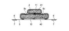
以下、本発明を、その好ましい実施形態に基づき図面を参照して説明する。図1は、本発明の第1実施形態である生理用ナプキン(以降、ナプキンとも称す。)の肌当接面側(表面シート側)を模式的に示す平面図、図2は、図1のI−I線断面を模式的に示す横断面図、図3は、図1に示す生理用ナプキンにおける吸収体(コアラップシートで覆われた吸収性コア)の切断線の形成前の状態を模式的に示す斜視図である。 Hereinafter, the present invention will be described based on preferred embodiments with reference to the drawings. FIG. 1 is a plan view schematically showing a skin contact surface side (surface sheet side) of a sanitary napkin (hereinafter also referred to as a napkin) according to a first embodiment of the present invention, and FIG. FIG. 3 is a cross-sectional view schematically showing a cross section taken along line II, and FIG. 3 is a schematic view of a state before the formation of a cutting line of an absorbent body (absorbent core covered with a core wrap sheet) in the sanitary napkin shown in FIG. FIG.
第1実施形態のナプキン1は、肌当接面を形成する液透過性の表面シート2、非肌当接面を形成する液不透過性又は撥水性の裏面シート3、及びこれら両シート2,3間に介在された液保持性の吸収体4を備え、実質的に縦長の形状をしている。ナプキン1は、装着時に装着者の排泄部位に対向配置される前方部Aと、装着時に該前方部Aよりも背側(後方)に配される後方部Bとを、長手方向に有している。第1実施形態における前方部Aと後方部Bとの境界は、ナプキン1の長手方向の略中央に存する。 The
表面シート2及び裏面シート3は、吸収体4よりも大きな寸法を有し、吸収体4の長手方向両端から延出し、それらの延出部の端部において互いにヒートシール等により接合されてエンドシール部を形成している。表面シート2は、吸収体4の肌当接面側の全域を被覆しており、更に吸収体4の長手方向に沿った両側部を被覆し、吸収体4の非肌当接面側における左右両側部にまで達している。裏面シート3は、吸収体4の長手方向に沿った両側縁から外方に延出してフラップ部5を形成している。フラップ部5は、前方部Aにおいてナプキン1の幅方向の外方に更に延出しており、一対のウイング部6,6を形成している。ウイング部6は、ナプキン1の装着時にその非肌当接面側が下着のクロッチ部の外面側に折り返されて用いられ、該非肌当接面側には粘着部7が設けられている。また、裏面シート3の非肌当接面側における吸収体4の下方に位置する所定箇所にも、ナプキン1を下着等の着衣に固定する図示しない粘着部が設けられている。これらの粘着部は、ホットメルト粘着剤を所定箇所に塗布することにより設けられており、ナプキン1の使用前においてはフィルム、不織布、紙などからなる図示しない剥離シートによって被覆されている。 The
尚、本明細書において、肌当接面は、吸収性物品の装着時に装着者の肌側に向けられる面であり、非肌当接面は、吸収性物品の装着時に肌側とは反対側に向けられる面である。また、長手方向は、吸収性物品又はその構成部材の長手方向に沿う方向であり、幅方向は、該長手方向と直交する方向である。 In the present specification, the skin contact surface is a surface directed toward the skin side of the wearer when the absorbent article is mounted, and the non-skin contact surface is the side opposite to the skin side when the absorbent article is mounted. It is the surface that is directed to. The longitudinal direction is a direction along the longitudinal direction of the absorbent article or its constituent members, and the width direction is a direction orthogonal to the longitudinal direction.
吸収体4は、図1及び図3に示すように、その幅方向中央部の肌当接面側に隆起する前方中高部41及び後方中高部42を有している。これら2つの中高部41,42は、ナプキン1の長手方向に所定間隔を置いて配されている。吸収体4は、液保持性の吸収性コア及び該吸収性コアの肌当接面側を被覆する液透過性のコアラップシートを含んで構成されており、該吸収体4の一部である前方中高部41及び後方中高部42も、吸収性コアとそれを被覆するコアラップシートで構成されている。より具体的には、吸収体4は、ナプキン1の前方部Aの前端1a近傍から後方部Bの後端1b近傍に亘って延びる縦長の吸収性コアが1枚のコアラップシート12と共に一体化された下層吸収層40と、該下層吸収層40の肌当接面上に配置された上層吸収層とを具備し、該上層吸収層が、2個の吸収性コアが1枚のコアラップシート11と共に一体化されてなり、且つこれら2個の吸収性コアがナプキン1の長手方向に離間して配置されて、前記中高部41,42を別個に形成している。上層吸収層の斯かる構成により、ナプキン1の肌当接面側における幅方向中央部は、他の部分に比して嵩高の中高部となる。中高部41,42の間隔は、通常5〜30mm程度である。 As shown in FIGS. 1 and 3, the absorbent body 4 has a front middle-
中高部41,42(上層吸収層)は、図1に示すように、縦長で且つ下層吸収層40よりも幅狭で、その長手方向をナプキン1の長手方向に一致させて下層吸収層40の肌当接面上に配されている。前方中高部41は、平面視して角が丸みを帯びた矩形形状をしており、後方中高部42は、平面視してその前端(ナプキン1の長手方向前端1a寄りの端)から後端(ナプキン1の長手方向後端1b寄りの端)に向かって幅が漸次減少している先細りの形状をしている。中高部41,42それぞれの非肌当接面側と下層吸収層40の肌当接面側との間は、接着剤等の接合手段により接合されていても良い。 As shown in FIG. 1, the middle and
吸収体4を構成する前記吸収性コアは、図2及び図3に示すように、2枚の液透過性のコアラップシート11,12によって、中高部41,42(上層吸収層)の吸収性コアと下層吸収層40の吸収性コアとに個別に覆われている。即ち、コアラップシート11は、中高部41,42それぞれの吸収性コアの肌当接面側の全面を一体的に被覆しており、更に該吸収性コアそれぞれの長手方向に沿った両側部を一体的に被覆し、該吸収性コアそれぞれの非肌当接面側に達してその全面を一体的に被覆している。また、コアラップシート12は、下層吸収層40の吸収性コアの肌当接面側の全面を被覆しており、更に該吸収性コアの長手方向に沿った両側部を被覆し、該吸収性コアの非肌当接面側に達してその全面を被覆している。コアラップシート11,12と各吸収層の吸収性コアとの間は、所定の部位においてホットメルト粘着剤等の接合手段により接合されている。このように、吸収体4が、吸収性コアをコアラップシート11,12で被覆して構成されていることは、吸収体4の形状安定性の向上や、吸収性コアに粒子状の高吸水性樹脂を含ませた場合にはその担持状態の維持に有効である。 As shown in FIGS. 2 and 3, the absorbent core constituting the absorbent body 4 is composed of two liquid-permeable
ナプキン1の長手方向に隣接する中高部41,42の間には、コアラップシート11が存していると共に、図1に示すように、表面シート2及び吸収体4(コアラップシート11,12及び下層吸収層40の吸収性コア)が圧密化されて形成された中間溝8bが、該長手方向と直交する幅方向に延びている。より具体的には、ナプキン1の肌当接面(表面シート2の上面)には、前方中高部41を包囲する閉じた環状の溝8が形成されており、中間溝8bは該溝8の一部となっている。中間溝8bは、該中間溝8bに隣接する後方中高部42に向かって凸の略U字状に形成されており、そのU字状の頂部がナプキン1の幅方向中央に位置している。 The
溝8は、中間溝8bに加えて、前方中高部41の前方を挟んで中間溝8bと対称に形成された溝8aと、ナプキン1の長手方向に延びる一対の溝8c,8cとを有し、これらの溝8a,8b,8c,8cがそれぞれ端部で繋がって、前方中高部41を包囲する環状を形成している。溝8において、表面シート2、コアラップシート11,12及び下層吸収層40の吸収性コアが接合されて一体化されている。 The groove 8 includes, in addition to the
また、ナプキン1の肌当接面には、溝8に加えて、後方中高部42を囲む溝9、及び該溝9に囲まれ且つ後方中高部42の後端側を囲む溝10が形成されている。溝9,10は、中間溝8bよりも幅狭の略U字状に形成されている。中間溝8bと溝9とは繋がっていないが、両溝8b,9によって後方中高部42は実質的に包囲されている。このように、ナプキン1の肌当接面側に、表面シート2及び吸収体4が圧密化されてこれらが一体化された溝8,9,10が形成されていることにより、吸収体4の平面方向の液の拡散が効果的に抑制されるようになり、またヨレが防止できる。また、特に溝8b,9,10の存在により、ナプキン1の後方部Bの上向きの可撓性が高まり、これにより装着者の身体に対するナプキン1のフィット性が一層向上する。溝8,9,10は、例えばヒートエンボス加工により常法に従って形成することができる。溝8,9,10は、ヒートエンボス加工等によって多数の矩形状のシール部を連続的に形成して、線状となされており、表面シート2を下層吸収層40まで凹状に押し込んで形成されている。溝8,9,10の幅は、これらの溝による上述した効果を確実に奏させる観点から、好ましくは1〜8mm、更に好ましくは1〜4mmである。 In addition to the groove 8, a groove 9 surrounding the rear middle
第1実施形態のナプキン1の主たる特徴の一つは、ナプキン1の長手方向に隣接する前方中高部41及び後方中高部42それぞれの吸収性コアを一体的に被覆しているコアラップシート11における、該中高部41,42の間に位置する部位(以下、中間部ともいう)11cが、該コアラップシート11の他の部位に比して、該長手方向の張力が低減されている点にある。より具体的には、図1及び図3に示すように、コアラップシート11の中間部11cには、該コアラップシート11(中間部11c)をナプキン1の長手方向に切り離す2本の切断線15,16がナプキン1の幅方向に延びて形成されている。尚、図3は、切断線15,16の形成前の吸収体4の模式図である。切断線15,16は、平面視して後方中高部42に向かって凸の略U字状をしている。略U字状の切断線15,16の曲率は、同じく略U字状の中間溝8bの曲率と略同じとなっている。このように、切断線15,16によって中間部11cがナプキン1の幅方向の全長に亘って切断されていることにより、該中間部11cのナプキン1の長手方向の張力がゼロになっている。ここで、コアラップシート11の中間部11cは、コアラップシート11における、前方中高部41の後端41bと後方中高部42の前端42aとの間に位置する部位である。 One of the main features of the
切断線15,16と中間溝8bとは重なっていない。即ち、第1実施形態においては、切断線15,16は、中間溝8bを挟んでナプキン1の長手方向の前後それぞれに形成されている。切断線15,16は、それぞれ、中間溝8bの幅方向中央部(ナプキン長手方向中央部)を起点として、1〜15mm以内の領域に形成されていることが好ましい。尚、コアラップシート11における切断線15,16間に挟まれた部位は、は両切断線15,16間に存しており、且つ中間溝8bにおいて表面シート2、コアラップシート12及び下層吸収層40と一体化されている。 The cutting lines 15 and 16 and the
このように、第1実施形態のナプキン1においては、コアラップシート11の中間部11cのナプキン長手方向の張力が、中間溝8bの前後に形成された該コアラップシート11の切断線15,16によって、該コアラップシート11の他の部位に比して低減されていることにより、中間溝8bにおけるコアラップシート11及び該シート11の肌当接面側に配されている表面シート2の下層吸収層40の表面からの浮き上がりが防止され、中間溝8bの成形性が高められる。仮に、コアラップシート11の中間部11cの張力低減化がなされていないと、表面シート2及びコアラップシート11それぞれの中間溝8bを起点とした張力、並びに両シート2,11によって下方に押圧されている中高部41,42の吸収性コアの上向きの復元力により、中間溝8bにおける各シートの接合状態が破壊され、その結果、両シート2,11が下層吸収層40の表面から浮き上がるおそれがある。つまり、コアラップシート11の中間部11cの張力低減化は、前記張力及び前記復元力の中間溝8bの形成位置への伝達を抑制し、中間溝8bの成形性が高めるものである。 Thus, in the
ナプキン1における各部の形成材料について説明すると、表面シート2、裏面シート3及びコアラップシート11,12としては、当該技術分野において従来用いられている各種のものを特に制限なく用いることができる。表面シート2としては、例えば不織布や開孔フィルム等の液透過性のシートを用いることができる。裏面シート3は、液不透過性でも液透過性でも良く、例えば透湿性を有しない樹脂フィルムや、微細孔を有し、透湿性を有する樹脂フィルム、撥水不織布等の不織布、これらと他のシートとのラミネート体等を用いることができる。 The material for forming each part of the
吸収体4〔上層吸収層(中高部41,42),下層吸収層40〕を構成する前記吸収性コアとしては、当該技術分野において従来用いられている各種のものを特に制限なく用いることができ、例えば、木材パルプ、合繊繊維等の親水性繊維からなる繊維集合体、又は該繊維集合体に粒子状の高吸水性樹脂を保持させたもの等を用いることができる。前記吸収性コアを被覆するコアラップシート11,12としては、例えば、ティッシュペーパー等の紙や各種不織布、開孔フィルム等を用いることができる。下層吸収層40及び中高部41,42それぞれの吸収性コアの組成は、全て同一であっても良く、何れかが異なっていても良い。 As the absorptive core constituting the absorber 4 [upper layer absorbing layers (middle and
下層吸収層40の坪量は、吸収性能の観点から、好ましくは100〜500g/m2、更に好ましくは150〜350g/m2である。また、同様の観点から、前方中高部41の坪量は、好ましくは100〜700g/m2、更に好ましくは150〜600g/m2であり、前方中高部41の無荷重下における下層吸収層40の肌当接面側の面からの隆起高さは、好ましくは1〜30mm、更に好ましくは2〜15mmである。また、同様の観点から、後方中高部42の坪量は、好ましくは100〜700g/m2、更に好ましくは150〜600g/m2であり、後方中高部42の無荷重下における下層吸収層40の肌当接面側の面からの隆起高さは、好ましくは1〜20mm、更に好ましくは2〜10mmである。尚、ここで言う吸収層の坪量は、コアラップシート及び高吸水性樹脂を含まない坪量(繊維集合体の坪量)を意味する。The basis weight of the lower
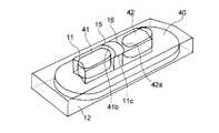
次に、本発明の吸収性物品の他の実施形態について図面を参照して説明する。後述する吸収性物品の他の実施形態については、上述した第1実施形態のナプキン1と異なる構成部分を主として説明し、同様の構成部分は同一の符号を付して説明を省略する。特に説明しない構成部分は、第1実施形態のナプキン1についての説明が適宜適用される。尚、図4〜図6においては、下層吸収層40の図示を省略している。また、図4及び図5では、説明容易のため、切断線17,18を、所定の幅で描いている Next, other embodiment of the absorbent article of this invention is described with reference to drawings. As for other embodiments of the absorbent article to be described later, components that are different from the
図4は、本発明の吸収性物品の第2実施形態である生理用ナプキンにおける吸収体の一部〔上層吸収層(中高部41,42)〕の溝の形成前(切断線の形成後)の状態を模式的に示す斜視図である。第1実施形態における切断線15,16は、コアラップシート11の中間部11cのナプキン幅方向の全幅に亘って形成されていたのに対し(図3参照)、第2実施形態における切断線17は、中間部11cのナプキン幅方向の中央部にのみ形成されており、中間部11cのナプキン幅方向の全幅に亘って形成されていない。切断線17は、中高部41,42それぞれの吸収性コアを被覆しているコアラップシート11における、吸収体4の肌当接面側(上面側)を形成している部位に1本存在している。切断線17によって、コアラップシート11の中間部11cは、そのナプキンの長手方向の張力が、ゼロとはなっていないものの、該コアラップシート11の他の部位と比較して低減されている。 FIG. 4 shows a part of the absorbent body of the sanitary napkin according to the second embodiment of the absorbent article of the present invention [before the upper absorbent layer (middle and
切断線17(即ちナプキン幅方向の長さが、コアラップシート11の中間部11cのナプキン幅方向の全幅未満である切断線)の長さL1と、切断線17形成前のコアラップシート11の中間部11cのナプキン幅方向の全幅(中間部11cの幅が一定でない場合は最大幅)Lとの比(L1/L)は、好ましくは0.2〜0.95、更に好ましくは0.4〜0.8である。また、切断線17の幅(切断線の長さ方向と直交する方向の長さ)は、中間部11cのナプキン長手方向に沿った長さP2(図6参照)以下である。 The length L1 of the cutting line 17 (that is, the cutting line whose length in the napkin width direction is less than the entire width of the
第2実施形態においては、切断線17と中間溝8b(図4では図示せず)とは重なっていても良く、重なっていなくても良い。中間溝8bにおける切断線17と重なっていない部位(非重複部)は、中間溝8bにおける切断線17と重なっている部位(重複部)に比して、当該溝8bにおいて接合されているシートの枚数が多いため、各シートがより強い接合力で接合される。従って、中間溝8bの一部あるいは全部を切断線17と重ならないように形成することは、各シートの浮き上がり防止に有効である。第2実施形態のナプキンによっても、第1実施形態のナプキンと同様の効果が奏される。 In the second embodiment, the cutting
図5は、本発明の吸収性物品の第3実施形態である生理用ナプキンにおける吸収体の一部〔上層吸収層(中高部41,42)〕の溝の形成前(切断線の形成後)の状態を模式的に示す斜視図である。第3実施形態のナプキンにおいては、コアラップシート11の中間部11cに、複数の切断線18a,18bが、それぞれ、ナプキン1の幅方向に所定間隔を置いて列をなすように配されており、該切断線18a,18bの列(図5ではそれぞれ3列)が、それぞれ、ナプキン1の長手方向に所定間隔を置いて配されている。切断線18aは、中高部41,42を被覆しているコアラップシート11における、吸収体4の肌当接面側(上面側)を形成する部位に5本存在しており、また、切断線18bは、該コアラップシート11における該部位と対向する部位に5本存在しており、各切断線18aと各切断線18bとが上下方向に相対向している。切断線18a,18bの大きさは略同じである。切断線18a,18bの幅は、第2実施形態における切断線17(図4参照)と同様にすることができる。 FIG. 5 shows a part of the absorbent body of the sanitary napkin according to the third embodiment of the absorbent article of the present invention [before the upper absorbent layer (middle and
第3実施形態においては、切断線18a,18bと中間溝8b(図5では図示せず)とは重なっていても良く、重なっていなくても良い。第3実施形態のナプキンによっても、第1実施形態のナプキンと同様の効果が奏される。 In the third embodiment, the
図6は、本発明の吸収性物品の第4実施形態である生理用ナプキンにおける吸収体の一部〔上層吸収層(中高部41,42)〕の張力低減化処理が施された状態を模式的に示す斜視図である。第4実施形態のナプキンにおいては、コアラップシート11の中間部11cに、該コアラップシート11の他の部位に比してナプキン長手方向の伸長率が高い高伸長部19が形成されている。尚、図6では、高伸長部19に凹凸(皴)が形成されているように記載しているが、実際の高伸長部には、必ずしもこのような明確な凹凸が形成されているわけではない。また、図6では、コアラップシート11の肌当接面側と非肌当接面側とに挟まれた側部における高伸長部19が、鉛直方向にまっすぐに起立しているように記載しているが、実際の該側部における高伸長部19は、必ずしもこのような起立した状態になっているわけではなく、肌当接面側及び非肌当接面側のナプキン長手方向に沿った側縁から外方に弛むように延出している場合もある。高伸長部19によって、コアラップシート11の中間部11cは、該シート11の他の部位(低又は非伸長部)に比して伸長性が高く、小さな力でより伸びやすくなっている。従って、高伸長部19が形成された中間部11cは、コアラップシート11の他の部位に比して、ナプキンの長手方向の張力が低減されている。 FIG. 6 is a schematic view showing a state in which a tension reducing process is performed on a part of the absorbent body [upper absorbent layer (middle and
高伸長部19は、中間部11cのナプキン長手方向の略中央部に形成され且つ当該部位の全幅に亘っている。高伸長部19のナプキン長手方向に沿った長さP1と、中間部11cのナプキン長手方向に沿った長さP2との比(P1/P2)は、好ましくは0.2〜1.0、更に好ましくは0.5〜1.0である。 The
高伸長部19は、コアラップシート11の中間部11cに延伸加工を施すことにより得られる。コアラップシートの延伸加工は、例えば後述するように、互いに噛み合う歯溝を有する一対のギアを用い、該ギアにシートを噛ませるギア延伸法によって行うことができる。ギアの形状は、歯溝を歯車状に噛み合わせた一対のギアロール(波状ロール)でも良く、平板状でも良い。 The
第4実施形態におけるコアラップシート11は、1)延伸加工前には伸長性又は伸縮性を有さず延伸加工により伸長性又は伸縮性を発現するシート、あるいは2)延伸加工前にも多少の伸長性又は伸縮性を有し延伸加工により伸長性又は伸縮性が向上するシートであることが好ましい。尚、伸長性とは、一方向に所定の引張荷重で引っ張ったときに該一方向に伸びることができる性質であり、該引張荷重を除いたときに、引っ張る前の元の長さに戻るか否かは問わない。また、伸縮性とは、一方向に所定の引張荷重で引っ張ったときに該一方向に伸び、且つ該引張荷重を除いたときに、引っ張る前の元の長さに略戻ることができる性質をいう。前記1)及び2)を満たすシートとしては、例えば、弾性繊維(スチレン系エラストマー、ポリオレフィン系エラストマー、ポリエステル系エラストマー、ポリウレタン系エラストマー等の熱可塑性エラストマー繊維)が含まれている不織布等が挙げられる。 The
高伸長部19の伸長率は、コアラップシート11の材質等によって異なるが、コアラップシート11が例えば弾性繊維を含んでいる不織布である場合は、好ましくは10%以上、更に好ましくは15%以上である。またその場合、コアラップシート11における延伸加工が施されていない低又は非伸長部(中間部11c以外の部位)は、手で引っ張る程度では、殆ど伸長しないか又は伸長しても僅かにしか伸長しない部位であり、該低又は非伸長部の伸長率は、10%未満である。コアラップシートの伸長率は、例えばギア延伸法で用いるギア形状(歯の高さや歯のピッチ等)を適宜調整することにより、調整することができる。伸長率は次のようにして測定される。 The elongation ratio of the
<伸長率の測定方法>
テンシロン等の引張試験機を用いてサンプルを引っ張って伸長率を測定する。測定対象物(シート)から所定サイズ(例えば、幅25mm、長さ50mm)のサンプルを用意する。サンプルをその長さ方向に1Nの引張荷重(即ち、サンプルのサイズが幅25mm、長さ50mmの場合、引張荷重は1N/25mm幅)で引っ張り、該サンプルが伸び止まったときのサンプル長さ(A)を測定し、下記式により伸長率(%)を算出する。 伸長率(%)=〔(A−50)/50〕×100。つまり、〔(引張荷重1.0Nで伸長後のサンプル長さ−伸長前のサンプル長さ)/(伸長前のサンプル長さ)〕×100である。例えばサンプルのサイズが幅25mm、長さ50mmの場合において、伸長後のサンプル長さが100mmの場合は伸長率は100%、伸長後のサンプル長さが150mmの場合は伸長率は200%である。<Measurement method of elongation rate>
The sample is pulled using a tensile tester such as Tensilon to measure the elongation. A sample of a predetermined size (for example, a width of 25 mm and a length of 50 mm) is prepared from the measurement object (sheet). The sample length (when the sample size is 25 mm and the length is 50 mm, the tensile load is 1 N / 25 mm width) is pulled in the length direction of the sample, and the sample length when the sample stops stretching ( A) is measured, and the elongation percentage (%) is calculated by the following formula. Elongation rate (%) = [(A-50) / 50] × 100. That is, [(sample length after stretching at a tensile load of 1.0 N−sample length before stretching) / (sample length before stretching)] × 100. For example, when the sample size is 25 mm wide and 50 mm long, the elongation rate is 100% when the sample length after elongation is 100 mm, and the elongation rate is 200% when the sample length after elongation is 150 mm. .
第4実施形態においては高伸長部19と中間溝8b(図6では図示せず)とが重なっていても良く、重なっていなくても良い。高伸長部と中間溝とが重なっているとは、コアラップシートの高伸長部に、中間溝の一部又は全部が形成されていることを意味する。高伸長部19と中間溝8bとが重なっている場合には、中間溝8bの柔軟性が高まり、装着感や風合いの向上に繋がる。また、高伸長部19と中間溝8bとが重なっていない場合には、中間溝8bは低又は非伸長部であるため、ナプキン装着時における吸収体4のヨレが効果的に防止される。第4実施形態のナプキンによっても、第1実施形態のナプキンと同様の効果が奏される。 In the fourth embodiment, the
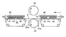
次に、本発明の吸収性物品の製造方法の好ましい実施態様を、上述した第1実施形態の生理用ナプキンの製造方法を例にとり図面を参照して説明する。図7は、生理用ナプキンの製造時における溝形成工程を模式的に示す図である。 Next, a preferred embodiment of the method for producing an absorbent article of the present invention will be described with reference to the drawings, taking the method for producing the sanitary napkin of the first embodiment as an example. FIG. 7 is a diagram schematically showing a groove forming step in manufacturing a sanitary napkin.
本実施態様の製造方法においては、先ず、一方向に所定間隔を置いて配置された複数(2個)の吸収性コアをその配置形態を維持したままコアラップシート11で包むことにより、該複数の吸収性コアが該コアラップシート11と共に一体化された上層吸収層(中高部41,42)と、該一方向に長い1個の吸収性コアがコアラップシート12で包まれてなる下層吸収層40とを含む被覆体50(図7参照)の連続体を製造する。被覆体50は、第1実施形態のナプキン1における吸収体4に相当するものであり、被覆体50の連続体は、後述するように個々の被覆体50に分離される。また、前記一方向(複数の吸収性コアが列をなす方向)は、完成品であるナプキンの長手方向に一致する。帯状のコアラップシート11は、一組の中高部41,42それぞれの吸収性コアを一体的に被覆し、帯状のコアラップシート12は、下層吸収層40の吸収性コアの連続体を被覆している。前記上層吸収層(中高部41,42)及び下層吸収層40は、公知の装置を用いて常法に従って製造することができる。前記上層吸収層における吸収性コアとコアラップシート11との間、下層吸収層40における吸収性コアとコアラップシート12との間、及び前記上層吸収層と下層吸収層40との間(コアラップシート11,12の間)は、それぞれ必要に応じ接着剤あるいは公知のシール法により接合する。 In the manufacturing method of the present embodiment, first, a plurality of (two) absorbent cores arranged at a predetermined interval in one direction are wrapped with the
次に、こうして吸収性コアが帯状のコアラップシート11,12で包まれてなる前記上層吸収層と下層吸収層40とを含む被覆体50の連続体に対し、該連続体における、前記一方向(被覆体50の搬送方向)に隣接する中高部41,42の間に位置するコアラップシート11に、該コアラップシート11の該一方向の張力を低減させる張力低減化処理を施す。より具体的には、帯状のコアラップシート11の中間部11c(帯状のコアラップシート11における、前記一方向に隣接する一組の中高部41,42の間に位置する部位)を切断し、該シート11を該一方向に切断する切断線15,16(図3参照)を形成する。これにより、帯状のコアラップシート11の該一方向の張力がゼロとされる。シート11の切断は、公知のカッター等を用いて行うことができる。尚、このように、コアラップシート11で一体的に包まれた中高部41,42(上層吸収層)を切断線15,16で切断する場合には、切断された中高部41,42を下方から支持する支持体があった方が製造上好ましく、本実施態様では、下層吸収層40の連続体が該支持体としての役割を果たしている。 Next, with respect to the continuous body of the covering 50 including the upper absorbent layer and the lower
前記張力低減化処理が施された、即ち上層吸収層を被覆する帯状のコアラップシート11に切断線15,16が形成された、被覆体50の連続体は、個々の被覆体50に分離された後、溝形成工程によって所定部位に溝8,9,10(図1参照)が形成される。溝形成工程では、図7に示すように、張力低減化処理が施された被覆体50における中高部41,42の表面に、帯状の表面シート2’を供給した後、前記一方向(被覆体50の搬送方向)に隣接する中高部41,42の間を含む該被覆体50の所定部位を、該表面シート2’側から圧搾ロール61で圧搾して、該所定部位に溝8,9,10を形成する。即ち、溝8,9,10は、被覆体50の中高部41,42を表面シート2’に接触させて両者を積層させた状態で、所定温度に加熱された圧搾ロール61と、圧力を受け止めるアンビルロール62との間を通過させることによって、表面シート2’側から圧搾ロール61の周面部に突出形成されたエンボス溝用突部61aによる圧搾によって形成される。尚、本実施態様においては、図7に示すように、被覆体50の搬送装置上に帯状の表面シート2’を置き、その上に個々に分離された被覆体50の上下を逆にしたものを置いており、こうして被覆体50の表面シート2’側を下方に向けた状態で、該被覆体50の下方に位置する圧搾ロール61のエンボス溝用突部61aによって圧搾を行っている。また、図示していないが、エンボス溝用突部61aは、溝8,9,10に対応したパターンで形成されており、圧搾ロール61に一定の押圧力が加えられた状態で、該圧搾ロール61が回転しながら、エンボス溝用突部61aの先端が順次被覆体50に該2’側から接触することにより、図1に示す如きパターンの溝8,9,10が形成される。 The continuous body of the covering
前記溝形成工程の終了後、図示しない帯状の裏面シートを供給して、被覆体50を該裏面シートと表面シート2’とで挟み、次いで、両シートにおける被覆体50からの延出部を、所定部位でヒートシール等のシール法により接合してエンドシール部を形成した後、個々のナプキンに分離することにより、第1実施形態の生理用ナプキンが得られる。 After completion of the groove forming step, a belt-like back sheet (not shown) is supplied, and the covering 50 is sandwiched between the back sheet and the
尚、前記実施態様では、吸収性コアがコアラップシート12で被覆されてなる下層吸収層40との上に、複数の吸収性コアがコアラップシート11で被覆されて両者が一体化されてなる上層吸収層(中高部41,42)とが重ね合わされた状態で、該コアラップシート11に張力低減化処理を施したが、両層を重ね合わせる前に、上層吸収層を構成しているコアラップシート11に張力低減化処理を施し、しかる後、両層を重ね合わせても良い。 In the above embodiment, a plurality of absorbent cores are covered with the
また、図4に示す第2実施形態のナプキン及び図5に示す第3実施形態のナプキンも、それぞれ上述した製造方法に準じて製造することができる。第2及び第3実施形態では、張力低減化処理においてコアラップシート11の中間部11cに形成する切断線17,18のナプキン幅方向の長さが、該中間部11cのナプキン幅方向の全幅未満であり、該中間部11cは該切断線で切り離されないため、第2及び第3実施形態における切断線の形成(張力低減化処理)は、下層吸収層40の有無に関係なく容易に行うことができる。 Moreover, the napkin of 2nd Embodiment shown in FIG. 4 and the napkin of 3rd Embodiment shown in FIG. 5 can each be manufactured according to the manufacturing method mentioned above. In the second and third embodiments, the length in the napkin width direction of the
また、図6に示す第4実施形態のナプキン、即ち、コアラップシート11の中間部11cに高伸長部19が形成されているナプキンを製造する場合には、前記張力低減化処理として、上述した帯状のコアラップシート11の中間部11cの切断処理に代えて、ギア延伸法を用いた延伸加工を行う。即ち、図8に示すように、帯状のコアラップシート11の中間部11cを、互いに噛み合う歯溝を有する一対の挟持体71,72間に噛み込ませて前記一方向(被覆体50の搬送方向)に延伸し、図6に示す如き高伸長部19を形成する。尚、このように、上層吸収層(中高部41,42)及び下層吸収層40からなる積層体における該上層吸収層を構成するコアラップシート11に延伸加工を施す場合には、下層吸収層40が存在すると該延伸加工が困難になるため、該延伸加工は、図8に示すように下層吸収層40無しで行うことが好ましい。 Moreover, when manufacturing the napkin of 4th Embodiment shown in FIG. 6, ie, the napkin in which the high expansion |
一対の挟持体71,72それぞれの被延伸加工物との対向面には、所定の高さを有する歯71a,72aが形成されており、挟持体71,72の歯溝どうしを互いに噛み合わせたときに、両挟持体の歯溝が所定の噛み合い深さで噛み合うようになされている。そのため、被延伸加工物(コアラップシート11の中間部11c)における、相対向する歯溝間に噛み込まれた部分(高伸長部19)は、該被延伸加工物の搬送方向に伸長され、優れた伸長性を発現する高伸長領域となる。
以上、本発明をその好ましい実施形態に基づき説明したが、本発明は前記実施形態に制限されない。例えば、前記実施形態では本発明の吸収性物品の適用例の一つとして生理用ナプキンを挙げたが、例えばパンティライナー(おりものシート)、失禁パッド等にも適用できる。また、コアラップシート11の中間部11c(前方中高部41と後方中高部42との間)に加えて、該コアラップシート11における、前方中高部41のナプキン長手方向の前端近傍に位置する溝8aと同位置若しくはその近傍、並びに/又は、後方中高部42のナプキン長手方向の後端近傍に位置する溝10と同位置若しくはその近傍に、張力低減化処理を施しても良い。 As mentioned above, although this invention was demonstrated based on the preferable embodiment, this invention is not restrict | limited to the said embodiment. For example, in the above embodiment, a sanitary napkin is given as an example of application of the absorbent article of the present invention, but it can also be applied to, for example, panty liners (orimono sheets), incontinence pads, and the like. Further, in addition to the
また、前記実施形態のナプキンは、長手方向に中高部を2つ有していたが、長手方向に3つ以上有していても良い。中高部が長手方向に所定間隔を置いて3つ以上配されていると、長手方向に隣接する中高部の間が2つ以上存在することになり、複数の該中高部の間それぞれに、幅方向に延びる中間溝を形成することができる。このように複数の中間溝が存在する場合、各中間溝に対応して、上述したコアラップシートの張力低減化を図ることができる。また、中高部は下層吸収層と一体的に形成されていても良い。 Moreover, although the napkin of the said embodiment had two middle-high parts in the longitudinal direction, you may have three or more in the longitudinal direction. When three or more middle-high portions are arranged at predetermined intervals in the longitudinal direction, there are two or more spaces between the middle-high portions adjacent to each other in the longitudinal direction. An intermediate groove extending in the direction can be formed. When there are a plurality of intermediate grooves as described above, the tension of the core wrap sheet described above can be reduced corresponding to each intermediate groove. Moreover, the middle-high part may be formed integrally with the lower layer absorption layer.
また前記実施形態では、中高部41,42(上層吸収層)それぞれの吸収性コアと下層吸収層40の吸収性コアとは、2枚のコアラップシート11,12によってそれぞれ個別に被覆されていたが、上層吸収層の吸収性コアと下層吸収層40の吸収性コアとの積層体が一枚のコアラップシートで一体的に被覆されていても良い。また、コアラップシートは吸収性コアの肌当接面側を被覆していればよく、非肌当接面側を被覆していなくてもよい。 Moreover, in the said embodiment, the absorptive core of each middle-
また、中間溝8bは平面視して略U字状に湾曲していたが、略V字状に屈曲していても良く、ナプキン1の幅方向に延びる直線状であっても良い。また、溝8aと中間溝8bとは前方中高部41を挟んで対称に形成されていたが、両溝8a,8bは対称でなくても良い。また、中間溝8bと溝9とは繋がっていても良い。 The
また、本発明においては、溝における表面シート等の浮きを一層効果的に抑え、溝の成形性を更に高める観点から、上述したコアラップシートの張力低減化に加えて、更に、当該溝において一体化されている部材(表面シート、コアラップシート、吸収性コア)における当該溝及びその近傍部位に、水分を付与(水を散布)しても良い。このような、水分付与による溝の成形性向上効果は、前記部材がパルプ繊維等の親水性繊維を含んで構成されている場合に特に有効であり、該部材間に生じる水素結合力等によって該部材間の接合力が一層高まり、表面シート等の浮き上がり防止に有効に作用する。 Further, in the present invention, in addition to the above-described reduction in the tension of the core wrap sheet, in addition to the above-described reduction in the tension of the core wrap sheet, from the viewpoint of more effectively suppressing the floating of the surface sheet or the like in the groove and further improving the moldability of the groove, Moisture may be applied (sprayed with water) to the groove and its vicinity in the formed member (surface sheet, core wrap sheet, absorbent core). Such an effect of improving the moldability of the groove due to moisture application is particularly effective when the member includes a hydrophilic fiber such as pulp fiber. The bonding force between the members is further increased, and effectively acts to prevent the surface sheet and the like from being lifted.
1 生理用ナプキン(吸収性物品)
2 表面シート
3 裏面シート
4 吸収体
8,9,10 溝
8b 中間溝
11,12 コアラップシート
15,16,17,18a,18b 切断線
19 高伸長部
40 下層吸収層
41 前方中高部
42 後方中高部
61 圧搾ロール
61a エンボス溝用突部
71,72 歯溝を有する一対の挟持体
71a,72a 歯
A 前方部
B 後方部1 Sanitary napkin (absorbent article)
2
Claims (10)
Translated fromJapanese前記吸収体は、その幅方向中央領域の肌当接面側に隆起する中高部を有しており、該中高部は、別個に設けられる前方中高部及び後方中高部とからなり、該前方中高部と該後方中高部との間には、前記表面シート及び該吸収体が圧密化されて形成される中間溝が前記吸収性物品の幅方向に延びて形成されており、
前記コアラップシートにおける、前記前方中高部と前記後方中高部との間に位置する部位は、該コアラップシートの他の部位に比して、前記吸収性物品の長手方向の張力が低減されている吸収性物品。A surface sheet that forms a skin contact surface, a back sheet that forms a non-skin contact surface, and an absorbent body interposed between the two sheets, the absorbent body comprising an absorbent core and the skin contact of the absorbent core An absorbent article configured to include a core wrap sheet covering the surface side,
The absorbent body has a mid-high portion that protrudes toward the skin contact surface side in the center region in the width direction, and the mid-high portion includes a front mid-high portion and a rear mid-high portion that are separately provided, and the front mid-height An intermediate groove formed by consolidating the topsheet and the absorbent body is formed extending in the width direction of the absorbent article between the portion and the rear middle high portion,
In the core wrap sheet, the portion located between the front middle high portion and the rear middle high portion has a reduced tension in the longitudinal direction of the absorbent article as compared to other portions of the core wrap sheet. Absorbent article.
前記吸収体は、下層吸収層と、該下層吸収層の肌当接面上に配置された上層吸収層とを具備し、該上層吸収層は、前記前方中高部及び前記後方中高部を形成する複数の吸収性コアを含んでおり、
一方向に所定間隔を置いて配置された前記上層吸収層用の複数の吸収性コアをその配置形態を維持したままコアラップシートで包むことにより、該複数の吸収性コアが該コアラップシートと共に一体化された該上層吸収層を含む被覆体を得、該被覆体における、該一方向に隣接する該上層吸収層用の吸収性コアの間に位置する該コアラップシートに、該コアラップシートの該一方向の張力を低減させる張力低減化処理を施す工程と、
前記張力低減化処理が施された前記被覆体における前記上層吸収層の一面に表面シートを供給した後、前記一方向に隣接する前記上層吸収層用の吸収性コアの間を含む該被覆体の所定部位を、該表面シート側から加圧手段で圧搾して、該所定部位に溝を形成する工程とを有している吸収性物品の製造方法。It is a manufacturing method of the absorptive article according to claim 1,
The absorber includes a lower layer absorbent layer and an upper layer absorbent layer disposed on the skin contact surface of the lower layer absorbent layer, and the upper layer absorbent layer forms the front middle high part and the rear middle high part. Contains multiple absorbent cores,
By wrappingthe plurality of absorbent coresfor the upper absorbent layer arranged at a predetermined interval in one direction with a core wrap sheet while maintaining the arrangement form, the plurality of absorbent cores are combined with the core wrap sheet. A covering including theupper absorbent layer integrated is obtained, and the core wrap sheet is disposed on the core wrap sheet positioned betweenthe absorbent coresfor the upper absorbent layer adjacent in the one direction in the covering. Applying a tension reducing process to reduce the unidirectional tension of
After feeding topsheeton one side ofthe upper absorbent layer in the covering body, wherein the tension reducing process has been performed, the said coating comprising between absorbent corefor the upper absorbent layer adjacent to said one direction The manufacturing method of an absorbent article which has a process which squeezes a predetermined part with a pressurization means from the surface sheet side, and forms a slot in this predetermined part.
Priority Applications (1)
| Application Number | Priority Date | Filing Date | Title |
|---|---|---|---|
| JP2008297623AJP5199040B2 (en) | 2008-11-21 | 2008-11-21 | Absorbent article and manufacturing method thereof |
Applications Claiming Priority (1)
| Application Number | Priority Date | Filing Date | Title |
|---|---|---|---|
| JP2008297623AJP5199040B2 (en) | 2008-11-21 | 2008-11-21 | Absorbent article and manufacturing method thereof |
Publications (2)
| Publication Number | Publication Date |
|---|---|
| JP2010119743A JP2010119743A (en) | 2010-06-03 |
| JP5199040B2true JP5199040B2 (en) | 2013-05-15 |
Family
ID=42321605
Family Applications (1)
| Application Number | Title | Priority Date | Filing Date |
|---|---|---|---|
| JP2008297623AActiveJP5199040B2 (en) | 2008-11-21 | 2008-11-21 | Absorbent article and manufacturing method thereof |
Country Status (1)
| Country | Link |
|---|---|
| JP (1) | JP5199040B2 (en) |
Families Citing this family (44)
| Publication number | Priority date | Publication date | Assignee | Title |
|---|---|---|---|---|
| ES2428693T3 (en) | 2003-02-12 | 2013-11-08 | The Procter & Gamble Company | Absorbent core for an absorbent article |
| EP1913914B2 (en) | 2003-02-12 | 2014-08-06 | The Procter and Gamble Company | Absorbent core for an absorbent article |
| DE112008000010B4 (en) | 2007-06-18 | 2013-08-22 | The Procter & Gamble Company | Disposable absorbent article having a substantially continuously dispersed particulate polymeric absorbent material and method of making the same |
| GB2454301B (en) | 2007-06-18 | 2012-03-28 | Procter & Gamble | Disposable absorbent article with sealed absorbent core with substantially continuously distributed absorbent particulate polymer material |
| EP2285326A1 (en) | 2008-04-29 | 2011-02-23 | The Procter & Gamble Company | Process for making an absorbent core with strain resistant core cover |
| EP2329803B1 (en) | 2009-12-02 | 2019-06-19 | The Procter & Gamble Company | Apparatus and method for transferring particulate material |
| EP2532329B1 (en) | 2011-06-10 | 2018-09-19 | The Procter and Gamble Company | Method and apparatus for making absorbent structures with absorbent material |
| JP5940655B2 (en) | 2011-06-10 | 2016-06-29 | ザ プロクター アンド ギャンブル カンパニー | Absorbent core for disposable absorbent articles |
| DE202012013608U1 (en) | 2011-06-10 | 2018-04-30 | The Procter & Gamble Company | Absorption structure for absorbent article |
| ES2459724T3 (en) | 2011-06-10 | 2014-05-12 | The Procter & Gamble Company | Method and apparatus for making absorbent structures with absorbent material |
| PL3284449T3 (en) | 2011-06-10 | 2020-03-31 | The Procter & Gamble Company | Disposable diapers |
| EP2532332B2 (en) | 2011-06-10 | 2017-10-04 | The Procter and Gamble Company | Disposable diaper having reduced attachment between absorbent core and backsheet |
| CA2838432C (en) | 2011-06-10 | 2018-02-27 | The Procter & Gamble Company | Absorbent structure for absorbent articles |
| JP5846870B2 (en)* | 2011-11-17 | 2016-01-20 | 花王株式会社 | Absorbent articles |
| JP6366220B2 (en)* | 2012-08-31 | 2018-08-01 | 花王株式会社 | Method for manufacturing absorbent article |
| MX348890B (en) | 2012-11-13 | 2017-07-03 | Procter & Gamble | Absorbent articles with channels and signals. |
| PL2740452T3 (en) | 2012-12-10 | 2022-01-31 | The Procter & Gamble Company | Absorbent article with high absorbent material content |
| US10639215B2 (en) | 2012-12-10 | 2020-05-05 | The Procter & Gamble Company | Absorbent articles with channels and/or pockets |
| US8979815B2 (en) | 2012-12-10 | 2015-03-17 | The Procter & Gamble Company | Absorbent articles with channels |
| US9216118B2 (en) | 2012-12-10 | 2015-12-22 | The Procter & Gamble Company | Absorbent articles with channels and/or pockets |
| PL2740449T3 (en) | 2012-12-10 | 2019-07-31 | The Procter & Gamble Company | Absorbent article with high absorbent material content |
| US9216116B2 (en) | 2012-12-10 | 2015-12-22 | The Procter & Gamble Company | Absorbent articles with channels |
| EP2740450A1 (en) | 2012-12-10 | 2014-06-11 | The Procter & Gamble Company | Absorbent core with high superabsorbent material content |
| AU2014233180B2 (en)* | 2013-03-15 | 2018-07-05 | Dsg Technology Holdings Ltd | Multi-layered absorbent article |
| DE202014011107U1 (en) | 2013-06-14 | 2017-12-15 | The Procter & Gamble Company | When wet, channels forming absorbent article and absorbent core |
| US9987176B2 (en) | 2013-08-27 | 2018-06-05 | The Procter & Gamble Company | Absorbent articles with channels |
| US9789011B2 (en) | 2013-08-27 | 2017-10-17 | The Procter & Gamble Company | Absorbent articles with channels |
| JP6169800B2 (en) | 2013-09-16 | 2017-07-26 | ザ プロクター アンド ギャンブル カンパニー | Absorbent articles with channels and labels |
| US11207220B2 (en) | 2013-09-16 | 2021-12-28 | The Procter & Gamble Company | Absorbent articles with channels and signals |
| EP2851048B1 (en) | 2013-09-19 | 2018-09-05 | The Procter and Gamble Company | Absorbent cores having material free areas |
| EP2886092B1 (en) | 2013-12-19 | 2016-09-14 | The Procter and Gamble Company | Absorbent cores having channel-forming areas and c-wrap seals |
| US9789009B2 (en) | 2013-12-19 | 2017-10-17 | The Procter & Gamble Company | Absorbent articles having channel-forming areas and wetness indicator |
| EP2905001B1 (en) | 2014-02-11 | 2017-01-04 | The Procter and Gamble Company | Method and apparatus for making an absorbent structure comprising channels |
| EP2949300B1 (en) | 2014-05-27 | 2017-08-02 | The Procter and Gamble Company | Absorbent core with absorbent material pattern |
| JP5859622B1 (en)* | 2014-10-01 | 2016-02-10 | ユニ・チャーム株式会社 | Absorbent articles |
| WO2016149251A1 (en) | 2015-03-16 | 2016-09-22 | The Procter & Gamble Company | Absorbent articles with improved cores |
| EP3270857B1 (en) | 2015-03-16 | 2019-12-04 | The Procter and Gamble Company | Absorbent articles with improved strength |
| US10736795B2 (en) | 2015-05-12 | 2020-08-11 | The Procter & Gamble Company | Absorbent article with improved core-to-backsheet adhesive |
| JP6743057B2 (en) | 2015-05-29 | 2020-08-19 | ザ プロクター アンド ギャンブル カンパニーThe Procter & Gamble Company | Absorbent article having channels and wetness indicators |
| EP3167859B1 (en) | 2015-11-16 | 2020-05-06 | The Procter and Gamble Company | Absorbent cores having material free areas |
| EP3238678B1 (en) | 2016-04-29 | 2019-02-27 | The Procter and Gamble Company | Absorbent core with transversal folding lines |
| JP6396368B2 (en)* | 2016-06-30 | 2018-09-26 | ユニ・チャーム株式会社 | Absorbent articles |
| KR101966248B1 (en)* | 2016-08-31 | 2019-04-05 | 유니 참 코포레이션 | Absorber and method of manufacturing absorbent article |
| JP2024088112A (en)* | 2022-12-20 | 2024-07-02 | ユニ・チャーム株式会社 | Absorbent sheet |
Family Cites Families (3)
| Publication number | Priority date | Publication date | Assignee | Title |
|---|---|---|---|---|
| JP4401309B2 (en)* | 2005-03-03 | 2010-01-20 | 花王株式会社 | Absorbent articles |
| JP4540107B2 (en)* | 2005-03-31 | 2010-09-08 | 大王製紙株式会社 | Absorbent article and manufacturing method thereof |
| JP4913381B2 (en)* | 2005-09-26 | 2012-04-11 | ユニ・チャーム株式会社 | Absorbent articles |
- 2008
- 2008-11-21JPJP2008297623Apatent/JP5199040B2/enactiveActive
Also Published As
| Publication number | Publication date |
|---|---|
| JP2010119743A (en) | 2010-06-03 |
Similar Documents
| Publication | Publication Date | Title |
|---|---|---|
| JP5199040B2 (en) | Absorbent article and manufacturing method thereof | |
| JP5329930B2 (en) | Absorbent article and manufacturing method thereof | |
| TWI479060B (en) | Absorbent article | |
| JP4058281B2 (en) | Absorbent articles | |
| CN102245143B (en) | Wearable article and manufacturing method thereof | |
| JP5411663B2 (en) | Absorbent articles | |
| CN109152681B (en) | Absorbent article | |
| JP4312113B2 (en) | Sanitary napkin | |
| JP5529644B2 (en) | Absorbent article and manufacturing method thereof | |
| JP4909818B2 (en) | Disposable diaper manufacturing method | |
| JP4004317B2 (en) | Absorbent articles | |
| JP5410897B2 (en) | Method for manufacturing worn article | |
| KR101615416B1 (en) | Disposable wearing article | |
| JP2011125360A (en) | Absorbent article | |
| JP5848068B2 (en) | Disposable wearing items | |
| TW201300087A (en) | Absorbent article | |
| TWI568428B (en) | An absorbent structure, and an absorbent underwear article using the absorbent structure | |
| JP6761238B2 (en) | Absorbent article | |
| JP6547150B2 (en) | Pants-type absorbent article | |
| JP2013085831A (en) | Absorptive article | |
| JP6620336B2 (en) | Absorbent articles | |
| JP6668032B2 (en) | Absorbent articles | |
| JP2006280585A (en) | Absorbent article and its manufacturing method | |
| JP7362428B2 (en) | Body fluid absorption padding material and its manufacturing method | |
| JP7164370B2 (en) | absorbent article |
Legal Events
| Date | Code | Title | Description |
|---|---|---|---|
| A621 | Written request for application examination | Free format text:JAPANESE INTERMEDIATE CODE: A621 Effective date:20110912 | |
| A977 | Report on retrieval | Free format text:JAPANESE INTERMEDIATE CODE: A971007 Effective date:20121119 | |
| A131 | Notification of reasons for refusal | Free format text:JAPANESE INTERMEDIATE CODE: A131 Effective date:20121127 | |
| A521 | Request for written amendment filed | Free format text:JAPANESE INTERMEDIATE CODE: A523 Effective date:20130110 | |
| TRDD | Decision of grant or rejection written | ||
| A01 | Written decision to grant a patent or to grant a registration (utility model) | Free format text:JAPANESE INTERMEDIATE CODE: A01 Effective date:20130205 | |
| A61 | First payment of annual fees (during grant procedure) | Free format text:JAPANESE INTERMEDIATE CODE: A61 Effective date:20130207 | |
| FPAY | Renewal fee payment (event date is renewal date of database) | Free format text:PAYMENT UNTIL: 20160215 Year of fee payment:3 | |
| R151 | Written notification of patent or utility model registration | Ref document number:5199040 Country of ref document:JP Free format text:JAPANESE INTERMEDIATE CODE: R151 | |
| FPAY | Renewal fee payment (event date is renewal date of database) | Free format text:PAYMENT UNTIL: 20160215 Year of fee payment:3 | |
| R250 | Receipt of annual fees | Free format text:JAPANESE INTERMEDIATE CODE: R250 | |
| R250 | Receipt of annual fees | Free format text:JAPANESE INTERMEDIATE CODE: R250 | |
| R250 | Receipt of annual fees | Free format text:JAPANESE INTERMEDIATE CODE: R250 | |
| R250 | Receipt of annual fees | Free format text:JAPANESE INTERMEDIATE CODE: R250 | |
| R250 | Receipt of annual fees | Free format text:JAPANESE INTERMEDIATE CODE: R250 | |
| R250 | Receipt of annual fees | Free format text:JAPANESE INTERMEDIATE CODE: R250 | |
| R250 | Receipt of annual fees | Free format text:JAPANESE INTERMEDIATE CODE: R250 | |
| R250 | Receipt of annual fees | Free format text:JAPANESE INTERMEDIATE CODE: R250 | |
| R250 | Receipt of annual fees | Free format text:JAPANESE INTERMEDIATE CODE: R250 | |
| R250 | Receipt of annual fees | Free format text:JAPANESE INTERMEDIATE CODE: R250 |