JP5198404B2 - Humidity estimation apparatus and humidity estimation method - Google Patents
Humidity estimation apparatus and humidity estimation methodDownload PDFInfo
- Publication number
- JP5198404B2 JP5198404B2JP2009238557AJP2009238557AJP5198404B2JP 5198404 B2JP5198404 B2JP 5198404B2JP 2009238557 AJP2009238557 AJP 2009238557AJP 2009238557 AJP2009238557 AJP 2009238557AJP 5198404 B2JP5198404 B2JP 5198404B2
- Authority
- JP
- Japan
- Prior art keywords
- air
- supply
- estimated
- absolute humidity
- value
- Prior art date
- Legal status (The legal status is an assumption and is not a legal conclusion. Google has not performed a legal analysis and makes no representation as to the accuracy of the status listed.)
- Expired - Fee Related
Links
Images


Classifications
- F—MECHANICAL ENGINEERING; LIGHTING; HEATING; WEAPONS; BLASTING
- F24—HEATING; RANGES; VENTILATING
- F24F—AIR-CONDITIONING; AIR-HUMIDIFICATION; VENTILATION; USE OF AIR CURRENTS FOR SCREENING
- F24F11/00—Control or safety arrangements
- F24F11/30—Control or safety arrangements for purposes related to the operation of the system, e.g. for safety or monitoring
- F—MECHANICAL ENGINEERING; LIGHTING; HEATING; WEAPONS; BLASTING
- F24—HEATING; RANGES; VENTILATING
- F24F—AIR-CONDITIONING; AIR-HUMIDIFICATION; VENTILATION; USE OF AIR CURRENTS FOR SCREENING
- F24F11/00—Control or safety arrangements
- F24F11/62—Control or safety arrangements characterised by the type of control or by internal processing, e.g. using fuzzy logic, adaptive control or estimation of values
- F—MECHANICAL ENGINEERING; LIGHTING; HEATING; WEAPONS; BLASTING
- F24—HEATING; RANGES; VENTILATING
- F24F—AIR-CONDITIONING; AIR-HUMIDIFICATION; VENTILATION; USE OF AIR CURRENTS FOR SCREENING
- F24F2110/00—Control inputs relating to air properties
- F24F2110/10—Temperature
- F—MECHANICAL ENGINEERING; LIGHTING; HEATING; WEAPONS; BLASTING
- F24—HEATING; RANGES; VENTILATING
- F24F—AIR-CONDITIONING; AIR-HUMIDIFICATION; VENTILATION; USE OF AIR CURRENTS FOR SCREENING
- F24F2110/00—Control inputs relating to air properties
- F24F2110/20—Humidity
- F—MECHANICAL ENGINEERING; LIGHTING; HEATING; WEAPONS; BLASTING
- F24—HEATING; RANGES; VENTILATING
- F24F—AIR-CONDITIONING; AIR-HUMIDIFICATION; VENTILATION; USE OF AIR CURRENTS FOR SCREENING
- F24F2120/00—Control inputs relating to users or occupants
- F24F2120/10—Occupancy
- F24F2120/12—Position of occupants
- F—MECHANICAL ENGINEERING; LIGHTING; HEATING; WEAPONS; BLASTING
- F24—HEATING; RANGES; VENTILATING
- F24F—AIR-CONDITIONING; AIR-HUMIDIFICATION; VENTILATION; USE OF AIR CURRENTS FOR SCREENING
- F24F2120/00—Control inputs relating to users or occupants
- F24F2120/10—Occupancy
- F24F2120/14—Activity of occupants
Landscapes
- Engineering & Computer Science (AREA)
- Chemical & Material Sciences (AREA)
- Combustion & Propulsion (AREA)
- Mechanical Engineering (AREA)
- General Engineering & Computer Science (AREA)
- Physics & Mathematics (AREA)
- Fuzzy Systems (AREA)
- Mathematical Physics (AREA)
- Signal Processing (AREA)
- Air Conditioning Control Device (AREA)
Description
Translated fromJapanese本発明は、ビル、病院などの建物の室内の空調制御を行う空調機において、空調設定値の算出に利用する室内湿度値を推定する湿度推定装置および湿度推定方法に関する。 The present invention relates to a humidity estimation device and a humidity estimation method for estimating an indoor humidity value used for calculating an air conditioning set value in an air conditioner that performs air conditioning control in a room such as a building or a hospital.
一般的に、建築設備全体の消費エネルギーの約半分を空調関連のエネルギー消費が占めており、空調制御の省エネルギー化を推進することは建築設備全体の省エネルギー化に大きく貢献する。 In general, about half of the energy consumption of the entire building equipment is consumed by air conditioning-related energy, and the promotion of energy saving in air conditioning control greatly contributes to energy saving of the entire building equipment.
一方、アメニティ空間としての事務所ビル等の室内では、在室者の温熱感覚、いわゆる快適性を満足することが要求されている。この快適性の確保と省エネルギー化とは相反する面を持つものであるが、在室者が快適と感じる範囲を超えた過剰なエネルギー消費を抑えることによりエネルギーの無駄を省くことが可能である。 On the other hand, in a room such as an office building as an amenity space, it is required to satisfy the thermal sensation of the occupant, so-called comfort. While ensuring this comfort and saving energy are contradictory, it is possible to reduce energy waste by suppressing excessive energy consumption beyond the range in which the occupants feel comfortable.
そこで、快適性の確保と省エネルギー化とを両立させるために、PMVと呼ばれる快適性指数を用いた制御が広く採用されている。ここで、快適性指標PMVについて説明する。 Therefore, control using a comfort index called PMV is widely adopted in order to ensure both comfort and energy saving. Here, the comfort index PMV will be described.
PMVとは、暑さ、寒さに対する人間の温熱感覚に影響を与える変数として(a)空気温度、(b)相対湿度、(c)平均輻射温度、(d)気流速度、(e)活動量(人体の内部発熱量)、(f)着衣量の6つを用いて求められる快適性指標である。 PMV is a variable that affects human thermal sensation against heat and cold. (A) Air temperature, (b) Relative humidity, (c) Average radiation temperature, (d) Air velocity, (e) Activity ( It is a comfort index determined using six of the internal heat generation amount of the human body) and (f) the amount of clothes.
人の発熱量は対流による放射量、輻射による放熱量、人からの蒸発熱量、呼吸による放熱量および蓄熱量の合計で、これらの熱平衡式が成立している場合は、人体が熱的に中立であり、暑くも寒くもない快適状態である。逆に熱平衡式がくずれた場合に人体は暑さ寒さを感じる。 The amount of heat generated by a person is the sum of the amount of radiation generated by convection, the amount of heat released by radiation, the amount of heat evaporated from the person, the amount of heat released by breathing, and the amount of stored heat.If these thermal balance equations hold, the human body is thermally neutral. It is a comfortable state that is neither hot nor cold. Conversely, when the thermal balance equation breaks down, the human body feels hot and cold.
デンマーク工科大学のFanger教授は1967年に快適方程式の導出を発表し、これを出発点として人体の熱負荷と人間の温冷感を、欧米人の多数の被験者のアンケートから統計分析して結び付け、PMV(Predicted Mean Vote:予測平均回答)を提案した。これは近年ISO規格にも取り上げられ最近よく用いられるようになった。 In 1967, Prof. Fanger of the Danish Institute of Technology announced the derivation of the comfort equation, and using this as a starting point, the thermal load of the human body and the thermal sensation of humans were statistically analyzed from questionnaires of a large number of European and American subjects, PMV (Predicted Mean Vote) was proposed. In recent years, this has been taken up by the ISO standard and has recently been used frequently.
温冷感の指標となるPMVは、次の7段階評価尺度による数値として表す。 PMV, which is an index of thermal sensation, is expressed as a numerical value based on the following seven-level evaluation scale.
+3:暑い
+2:暖かい
+1:やや暖かい
0:どちらでもない、快適
−1:やや涼しい
−2:涼しい
−3:寒い
なお、人間の快適なPMV値の範囲は−0.5〜+0.5である。+3: Hot +2: Warm +1: Slightly warm 0: Neither comfortable, -1: Slightly cool -2: Cool -3: Cold Note that the range of comfortable human PMV values is -0.5 to +0.5 is there.
上記の6つの変数のうち、作業強度を表す活動量は通常、代謝量metの単位を用い、着衣量はcloの単位を用いる。 Of the above six variables, the amount of activity representing work intensity usually uses the unit of metabolic rate met, and the amount of clothing uses the unit of clo.
単位met(メット)は、代謝量を表し、熱的に快適な状態における安静時代謝を基準とし、1metは下記式(1)で表される。 The unit met (met) represents the amount of metabolism, and 1 met is represented by the following formula (1) with reference to resting metabolism in a thermally comfortable state.
〔数1〕
1met = 58.2 W/m2 = 50 kcal/m2・h (1)
また、単位clo(クロ)は、衣服の熱絶縁性を表し、1clo とは気温 21℃,相対湿度 50%,気流 5cm/s以下の室内で、体表面からの放熱量が1metの代謝と平衡するような着衣状態での値であり、通常の熱抵抗値に換算すると下記式(2)で表される。[Equation 1]
1met = 58.2 W / m2 = 50 kcal / m2 · h (1)
In addition, the unit clo (cloth) represents the thermal insulation of clothes, and 1 clo is a room temperature of 21 ° C, relative humidity 50%, air flow 5cm / s or less, and the amount of heat released from the body surface is balanced with metabolism of 1met. It is a value in such a clothing state, and is expressed by the following formula (2) when converted into a normal thermal resistance value.
〔数2〕
1clo = 0.155 m2・℃/W = 0.18 m2・h・℃/kcal (2)
下記式(3)を用いて快適な範囲内(−0.5<PMV<+0.5)で冷房時はより暑い方向の側に、暖房時はより寒い方向の側にPMV目標値を設定することで空調負荷の軽減を図ることができ、省エネルギーを達成できる。[Equation 2]
1clo = 0.155 m2 · ° C / W = 0.18 m2 · h · ° C / kcal (2)
Using the following formula (3), within the comfortable range (−0.5 <PMV <+0.5), the PMV target value is set on the hotter side during cooling and on the colder side during heating. Therefore, the air conditioning load can be reduced and energy saving can be achieved.
〔数3〕
A:人体表面積[m2]
L:人体熱負荷[kcal/m2h](Fangerの快適方程式より算定)
以上がPMVに関する説明である。[Equation 3]
A: Human body surface area [m2 ]
L: Human body heat load [kcal / m2 h] (calculated from Fanger's comfort equation)
The above is the description regarding PMV.
このPMV等を利用して在室者の快適性を確保しつつ省エネルギー化を実現する技術として、たとえば、特許文献1に記載の環境エネルギー管理システムがある。このシステムは、エージェント技術を応用した装置とシステムで構成し、エージェント装置が有する自律制御機能、論理グループ機能および階層化機能と、管理マネージャ装置が有するエージェント装置からのデータ収集機能、エージェント装置を一括管理・制御する機能、温熱環境計算とエネルギー最適化計算機能および得られた計算結果に基づく空気調和設備の制御機能により、室内の温熱環境の最適化とエネルギー消費の最小化の両立を実現している。 For example, there is an environmental energy management system described in
ところで、人間の快適性を左右するパラメータは、温度、湿度、風速など多くあるが、上記の特許文献1に記載の環境エネルギー管理システムでは、エージェント機能を活用して、温熱環境計算とエネルギー最適化計算機能および得られた計算結果に基づく空気調和設備の制御機能により、室内の温熱環境の最適化とエネルギー消費の最小化の両立を実現している。 By the way, there are many parameters that influence human comfort, such as temperature, humidity, and wind speed. However, in the environmental energy management system described in
しかし、人の感じる快適性は温熱環境のみでなく湿度にも大きく依存するため湿度環境の制御も望まれているが、多くの建物においては湿度測定器が設置されていないため、湿度環境の制御を行うことができないという問題があった。 However, since the comfort felt by humans depends not only on the thermal environment but also on the humidity, control of the humidity environment is also desired, but in many buildings no humidity measuring instrument is installed, so the humidity environment is controlled. There was a problem that could not be done.
本発明は上記事情に鑑みてなされたものであり、湿度測定器が設置されていない建物においても、空調制御に利用するための室内湿度値を推定することが可能な湿度推定装置および湿度推定方法を提供することである。 The present invention has been made in view of the above circumstances, and a humidity estimation device and a humidity estimation method capable of estimating an indoor humidity value for use in air conditioning control even in a building where a humidity measuring device is not installed Is to provide.
上記目的を達成するための本発明の湿度推定装置は、空調機の給気ファンの運転制御情報を取得し、この給気ファンの運転制御情報と、予め設定されたファン差圧とに基づいて、前記空調機の推定給気流量を算出する給気流量推定部と、前記空調機の給気温度値を取得し、この給気温度値と、予め設定された給気相対湿度値に関する給気温度値と給気絶対湿度値との関係に基づいて、前記空調機の推定給気絶対湿度値を算出する給気絶対湿度推定部と、前記空調機による制御対象の室内の室内温度値を取得し、この室内温度値と、入力された当該室内の在室者の人数および活動量とに基づいて、推定室内水蒸気発生量を算出する室内水蒸気発生量推定部と、前記空調機の推定給気絶対湿度値と前記推定給気流量との積と、前記推定室内水蒸気発生量との総和を、前記推定給気流量で割ることにより、単位給気流量あたりの水蒸気量で表した当該室内の推定絶対湿度値を算出する室内絶対湿度推定部とを備えることを特徴とする。In order to achieve the above object, a humidity estimating apparatus of the present invention acquires operation control information of an air supply fan of an air conditioner, and based on the operation control information of the supply fan and a preset fan differential pressure. , An air supply flow rate estimating unit for calculating an estimated air supply flow rate of the air conditioner, and obtainingan air supply temperature value of the air conditioner, and an air supply related to the air supply temperature value and apreset air supply relative humidity value Based on the relationship between the temperature value and the air supply absolute humidity value, the air supply absolute humidity estimation unit that calculates the estimated air supply absolute humidity value of the air conditioner, and the room temperature value of the room controlled by the air conditioner are acquired. An indoor water vapor generation amount estimation unit that calculates an estimated indoor water vapor generation amount based on the indoor temperature value and the number of persons in the room and the amount of activity input, and the estimated air supply of the air conditioner The product of the absolute humidity value and the estimated supply air flow rate, and the estimated indoor water vapor An indoor absolute humidity estimation unit that calculates an estimated absolute humidity value of the room represented by the amount of water vapor per unit supply air flow rate by dividing the total amount with the estimated supply air flow rate, To do.
また、本発明の湿度推定方法は、湿度推定装置が、前記空調機の給気ファンの運転制御情報を取得し、この給気ファンの運転制御情報と、予め設定されたファン差圧とに基づいて、前記空調機の推定給気流量を算出する給気流量推定ステップと、前記空調機の給気温度値を取得し、この給気温度値と、予め設定された給気相対湿度値に関する給気温度値と給気絶対湿度値との関係に基づいて、前記空調機の推定給気絶対湿度値を算出する給気絶対湿度推定ステップと、前記空調機による制御対象の室内の室内温度値を取得し、この室内温度値と、入力された当該室内の在室者の人数および活動量とに基づいて、推定室内水蒸気発生量を算出する室内水蒸気発生量推定ステップと、前記空調機の推定給気絶対湿度値と前記推定給気流量との積と、前記推定室内水蒸気発生量との総和を、前記推定給気流量で割ることにより、単位給気流量あたりの水蒸気量で表した当該室内の推定絶対湿度値を算出する室内絶対湿度推定ステップとを有することを特徴とする。Further, according to the humidity estimation method of the present invention, the humidity estimation device acquires the operation control information of the air supply fan of the air conditioner, and is based on the operation control information of the air supply fan and a preset fan differential pressure. The air supply flow rate estimating step for calculating the estimated air supply flow rate of the air conditioner, and the air supply temperature value of the air conditioner are acquired, and the air supply temperature value anda supply air relative humidity value set in advance are obtained.Based on the relationship between the air temperature value and the air supply absolute humidity value, the air supply absolute humidity estimating step for calculating the estimated air supply absolute humidity value of the air conditioner, and the room temperature value of the room to be controlled by the air conditioner An indoor water vapor generation amount estimating step of calculating an estimated indoor water vapor generation amount based on the acquired indoor temperature value and the number of persons in the room and the amount of activity input, and an estimated supply of the air conditioner The product of the absolute humidity value and the estimated air supply flow rate An indoor absolute humidity estimation step of calculating an estimated absolute humidity value in the room expressed by the amount of water vapor per unit supply air flow rate by dividing the sum of the estimated indoor water vapor generation amount by the estimated supply air flow rate. It is characterized by that.
本発明の湿度推定装置および湿度推定方法によれば、湿度測定器が設置されていない建物においても、空調制御に利用するための室内湿度値を推定することができる。 According to the humidity estimation apparatus and the humidity estimation method of the present invention, it is possible to estimate the indoor humidity value to be used for air conditioning control even in a building where no humidity measuring device is installed.
〈一実施形態による湿度推定装置の構成〉
本発明の一実施形態による湿度推定装置10の構成について、図1を参照して説明する。<Configuration of humidity estimation apparatus according to one embodiment>
A configuration of a
本実施形態における湿度推定装置10は建物の室内を空調する空調機内に設けられ、給気流量推定部11と、給気絶対湿度推定部12と、室内水蒸気発生量推定部13と、室内絶対湿度推定部14とを有する。本実施形態において、空調制御対象の室内には複数(n台)の空調機1〜nが設置されているものとする。 The
給気流量推定部11は、空調機1〜n内のDDC(Direct Digital Controller:図示せず)等から給気ファンの運転制御情報として制御中の給気ファンの回転数を取得し、この給気ファンの回転数と、予め設定されたファン差圧とに基づいて、空調機1〜nごとの推定給気流量を算出する。 The supply air
給気絶対湿度推定部12は、空調機1〜n内のDDC等から制御中の給気温度値を取得し、この給気温度値と、予め設定された給気相対湿度値とに基づいて空調機1〜nごとの推定給気絶対湿度値を算出する。 The supply air absolute
室内水蒸気発生量推定部13は、空調制御対象の室内に設置された温度センサから室内温度値を取得し、この室内温度値と、入力された当該室内の在室者の人数および活動量とに基づいて、推定室内水蒸気発生量を算出する。 The indoor water vapor generation
室内絶対湿度推定部14は、給気流量推定部11で算出された空調機1〜nごとの推定給気流量と、給気絶対湿度推定部12で算出された空調機1〜nごとの推定給気絶対湿度値と、室内水蒸気発生量推定部13で算出された推定室内水蒸気発生量とから、当該室内の推定湿度値を算出する。 The indoor
〈一実施形態による湿度推定装置の動作〉
次に、本実施形態による湿度推定装置10の動作について図2のフローチャートを参照して説明する。<Operation of Humidity Estimation Device According to One Embodiment>
Next, the operation of the
まず、給気流量推定部11において、空調機1〜n内のDDC等から給気ファンの運転制御情報として制御中の給気ファンの回転数(Maxの回転数を100%としたときの割合で示す)が取得され、この給気ファンの回転数と、予め設定されたファン差圧とに基づいて空調機1〜nごとの推定給気流量が算出される(S1)。 First, in the supply air flow
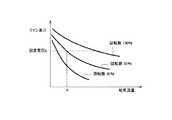
給気流量推定部11には、予め図3にグラフで示されるような給気ファンの複数の回転数(Maxの回転数を100%としたときの、例えば35%、50%、100%の回転数)に関するファン差圧と給気流量との関係を示す給気流量テーブルが保持されており、例えば取得された給気ファンの回転数が50%であり、予め設定された差圧がp値である場合、図3で示される推定給気流量テーブルに基づいて給気流量qが推定給気流量として算出される。この給気流量テーブルは、各給気ファンのファン特性に基づいて空調機1〜nごとに予め設定されている。 The supply air flow
また給気絶対湿度推定部12において、空調機1〜n内のDDC等から制御中の給気温度値が取得され、この給気温度値と、予め設定された給気相対湿度とに基づいて空調機1〜nごとの推定給気絶対湿度値が算出される。(S2)。 In addition, the supply air absolute
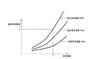
給気絶対湿度推定部12には、予め図4のグラフで示されるような、複数の給気相対湿度値(例えば50%、70%、90%)に関する給気温度値と給気絶対湿度値との関係を示す給気湿度テーブルが保持されており、例えば取得された給気温度値がr度であり、予め設定された給気相対湿度が90%である場合、図4の給気湿度テーブルに基づいて給気絶対湿度値sが推定絶対湿度値として算出される。この給気湿度テーブルは空気線図の一部であり、条件により変化せず固定された情報である。 In the supply air absolute
また、室内水蒸気発生量推定部13において、空調制御対象の室内に設置された温度センサから室内温度値が取得され、この室内温度値と、入力された当該室内の在室者の活動量および人数とに基づいて推定室内水蒸気発生量が算出される(S3)。 In addition, the indoor water vapor generation
室内水蒸気発生量推定部13には、予め図5のグラフで示されるような、複数の活動量Met(例えばMet=1.0、1.2、2.6)に関する室内温度値と一人の人から発生する水蒸気発生量との関係を示す水蒸気発生量テーブルが保持されており、例えば取得された室内温度値がt度であり、在室者の室内での活動状況に応じて予め設定された活動量Metが1.2である場合、図5の水蒸気発生量テーブルに基づいて一人の人から発生する水蒸気発生量uが推定水蒸気発生量として算出される。そして、この推定水蒸気発生量に在室者の人数がかけ合わせられることにより、空調制御対象の室内の推定室内水蒸気発生量が算出される。 In the indoor water vapor generation
次に、室内絶対湿度推定部14において、給気流量推定部11で算出された空調機1〜nごとの推定給気流量と、給気絶対湿度推定部12で算出された空調機1〜nごとの推定給気絶対湿度値と、室内水蒸気発生量推定部13で算出された推定室内水蒸気発生量とから、下記式(4)に基づいて当該室内の推定湿度値Hrが算出される(S4)。 Next, in the indoor absolute
〔数4〕
このようにして算出された当該室内の推定湿度値が利用されて各空調機1〜nにおいてPMVが算出され、空調制御対象の室内の空調制御に利用される。 The estimated humidity value calculated in this way is used to calculate the PMV in each of the
以上の本実施形態によれば、湿度測定器が設置されていない建物においても室内絶対湿度値を推定することができ、この推定された室内絶対湿度値が利用されることにより室内温度のみならず室内湿度も考慮した空調制御が可能となり、室内の温熱環境の最適化とエネルギー消費の最小化の両立に貢献することができる。 According to the present embodiment described above, the indoor absolute humidity value can be estimated even in a building in which no humidity measuring device is installed, and not only the indoor temperature but also the estimated indoor absolute humidity value is used. Air conditioning control that also considers indoor humidity is possible, which can contribute to both optimization of the indoor thermal environment and minimization of energy consumption.
本実施形態において、図3には給気ファンの回転数が、Maxの回転数を100%としたときの35%、50%、100%のときの給気流量テーブルを示したが、これら以外の回転数のときにはこれらの既知の回転数の値から補間処理により算出された値を用いて給気流量を推定することができる。 In this embodiment, FIG. 3 shows a supply air flow rate table when the rotation speed of the supply air fan is 35%, 50%, and 100% when the rotation speed of Max is 100%. When the rotation speed is, the supply air flow rate can be estimated using a value calculated by interpolation processing from these known rotation speed values.
また図4には給気相対湿度値が50%、70%、90%のときの給気湿度テーブルを示したが、設定された給気相対湿度がこれら以外の値のときにはこれらの既知の給気相対湿度値から補間処理により算出された値を用いて給気絶対湿度値を推定することができる。 FIG. 4 shows a supply air humidity table when the supply air relative humidity values are 50%, 70%, and 90%. However, when the set supply air relative humidity is a value other than these, these known supply air humidity values are shown. The supply absolute humidity value can be estimated using the value calculated by the interpolation process from the air relative humidity value.
また図5には活動量が1.0、1.2、2.6のときの水蒸気発生量テーブルを示したが、入力された活動量がこれら以外の値のときにはこれらの既知の活動量から補間処理により算出された値を用いて水蒸気発生量を推定することができる。 Further, FIG. 5 shows a water vapor generation amount table when the activity amount is 1.0, 1.2, and 2.6. When the input activity amount is a value other than these, it is calculated by interpolation processing from these known activity amounts. The water vapor generation amount can be estimated using the value.
また本実施形態においては、給気流量推定部11で推定給気流量を算出する際に運転制御情報として給気ファンの回転数を用いた場合について説明したが、これに替えて給気ファンの回転をインバータで制御する際の周波数値、または給気ファンの固定された複数の運転モードから選択された運転モード(例えば「強モード」、「中モード」、「弱モード」)を示す情報に基づいて推定給気流量を算出するようにしてもよい。この場合給気流量テーブルには、給気ファンの回転をインバータで制御する際の複数の周波数値、または給気ファンの運転モードに関するファン差圧と給気流量との関係を示す値を予め保持しておくものとする。 Moreover, in this embodiment, although the case where the rotation speed of the air supply fan was used as the operation control information when the estimated air supply flow rate was calculated by the air supply flow
10…湿度推定装置
11…給気流量推定部
12…給気絶対湿度推定部
13…室内水蒸気発生量推定部
14…室内絶対湿度推定部DESCRIPTION OF
Claims (5)
Translated fromJapanese前記空調機の給気温度値を取得し、この給気温度値と、予め設定された給気相対湿度値に関する給気温度値と給気絶対湿度値との関係に基づいて、前記空調機の推定給気絶対湿度値を算出する給気絶対湿度推定部と、
前記空調機による制御対象の室内の室内温度値を取得し、この室内温度値と、入力された当該室内の在室者の人数および活動量とに基づいて、推定室内水蒸気発生量を算出する室内水蒸気発生量推定部と、
前記空調機の推定給気絶対湿度値と前記推定給気流量との積と、前記推定室内水蒸気発生量との総和を、前記推定給気流量で割ることにより、単位給気流量あたりの水蒸気量で表した当該室内の推定絶対湿度値を算出する室内絶対湿度推定部とを備える
ことを特徴とする湿度推定装置。An air supply flow rate for obtaining air supply fan operation control information and calculating an estimated air supply flow rate of the air conditioner based on the operation control information of the air supply fan and a preset fan differential pressure. An estimation unit;
The supply air temperature value of the air conditioner is acquired,and based on the relationship between the supply air temperature value and the supply air temperature value and the supply air absolute humidity value related to apreset supply air relative humidity value , An air supply absolute humidity estimation unit for calculating an estimated air supply absolute humidity value;
A room that obtains an indoor temperature value of a room to be controlled by the air conditioner, and calculates an estimated indoor water vapor generation amount based on the indoor temperature value and the number of people in the room and the amount of activity input. A water vapor generation amount estimation unit;
By dividing the sum of the product of the estimated absolute supply air humidity value of the air conditioner and the estimated supply air flow rate and the estimated indoor water vapor generation amount by the estimated supply air flow rate, the amount of water vapor per unit supply air flow rate A humidity estimation apparatus comprising: an indoor absolute humidity estimation unit that calculates an estimated absolute humidity value of the room represented by
前記給気絶対湿度推定部では、前記複数の空調機ごとに推定給気絶対湿度値が算出され、
前記室内絶対湿度推定部では、前記複数の空調機ごとの、前記推定給気絶対湿度値と前記推定給気流量との積と、前記推定室内水蒸気発生量との総和を、前記複数の空調機ごとの推定給気流量の総和で割ることにより、単位給気流量あたりの水蒸気量で表した当該室内の推定絶対湿度値を算出する
ことを特徴とする請求項1に記載の湿度推定装置。In the supply air flow estimation unit, an estimated supply air flow is calculated for each of a plurality of air conditioners,
In the air supply absolute humidity estimation unit, an estimated air supply absolute humidity value is calculated for each of the plurality of air conditioners,
In the indoor absolute humidity estimation unit, for each of the plurality of air conditioners, the sum of the product of the estimated absolute air supply humidity value and the estimated supply air flow rate and the estimated indoor water vapor generation amount is calculated as the plurality of air conditioners. The humidity estimation apparatus according to claim 1, wherein the estimated absolute humidity value in the room expressed by the amount of water vapor per unit supply air flow is calculated by dividing by the total of the estimated supply air flow for each unit.
前記空調機の給気ファンの運転制御情報を取得し、この給気ファンの運転制御情報と、予め設定されたファン差圧とに基づいて、前記空調機の推定給気流量を算出する給気流量推定ステップと、
前記空調機の給気温度値を取得し、この給気温度値と、予め設定された給気相対湿度値に関する給気温度値と給気絶対湿度値との関係に基づいて、前記空調機の推定給気絶対湿度値を算出する給気絶対湿度推定ステップと、
前記空調機による制御対象の室内の室内温度値を取得し、この室内温度値と、入力された当該室内の在室者の人数および活動量とに基づいて、推定室内水蒸気発生量を算出する室内水蒸気発生量推定ステップと、
前記空調機の推定給気絶対湿度値と前記推定給気流量との積と、前記推定室内水蒸気発生量との総和を、前記推定給気流量で割ることにより、単位給気流量あたりの水蒸気量で表した当該室内の推定絶対湿度値を算出する室内絶対湿度推定ステップと
を有することを特徴とする湿度推定方法。Humidity estimation device
Air supply that obtains the operation control information of the air supply fan of the air conditioner and calculates the estimated air supply flow rate of the air conditioner based on the operation control information of the air supply fan and a preset fan differential pressure A flow estimation step;
The supply air temperature value of the air conditioner is acquired,and based on the relationship between the supply air temperature value and the supply air temperature value and the supply air absolute humidity value related to apreset supply air relative humidity value , A supply air absolute humidity estimation step for calculating an estimated air supply absolute humidity value;
A room that obtains an indoor temperature value of a room to be controlled by the air conditioner, and calculates an estimated indoor water vapor generation amount based on the indoor temperature value and the number of people in the room and the amount of activity input. A water vapor generation amount estimation step;
By dividing the sum of the product of the estimated absolute supply air humidity value of the air conditioner and the estimated supply air flow rate and the estimated indoor water vapor generation amount by the estimated supply air flow rate, the amount of water vapor per unit supply air flow rate And an indoor absolute humidity estimating step for calculating an estimated absolute humidity value of the room represented by
前記給気絶対湿度推定ステップでは、前記複数の空調機ごとに推定給気絶対湿度値が算出され、
前記室内絶対湿度推定ステップでは、前記複数の空調機ごとの、前記推定給気絶対湿度値と前記推定給気流量との積と、前記推定室内水蒸気発生量との総和を、前記複数の空調機ごとの推定給気流量の総和で割ることにより、単位給気流量あたりの水蒸気量で表した当該室内の推定絶対湿度値を算出する
ことを特徴とする請求項4に記載の湿度推定方法。In the supply air flow estimation step, an estimated supply air flow is calculated for each of a plurality of air conditioners,
In the air supply absolute humidity estimation step, an estimated air supply absolute humidity value is calculated for each of the plurality of air conditioners,
In the indoor absolute humidity estimation step, a sum of the product of the estimated supply absolute humidity value and the estimated supply air flow rate and the estimated indoor water vapor generation amount for each of the plurality of air conditioners is calculated as the plurality of air conditioners. The humidity estimation method according to claim 4, wherein the estimated absolute humidity value in the room expressed by the amount of water vapor per unit supply air flow is calculated by dividing by the sum of the estimated supply air flow for each unit.
Priority Applications (6)
| Application Number | Priority Date | Filing Date | Title |
|---|---|---|---|
| JP2009238557AJP5198404B2 (en) | 2009-10-15 | 2009-10-15 | Humidity estimation apparatus and humidity estimation method |
| KR1020100097652AKR101162582B1 (en) | 2009-10-15 | 2010-10-07 | Device and method for humidity estimation |
| SG201007400-3ASG170686A1 (en) | 2009-10-15 | 2010-10-08 | Device and method for humidity estimation |
| CN201010510804.8ACN102042659B (en) | 2009-10-15 | 2010-10-13 | Humidity estimation device and method |
| DE102010048340ADE102010048340A1 (en) | 2009-10-15 | 2010-10-13 | Apparatus and method for determining moisture |
| US12/903,640US8615327B2 (en) | 2009-10-15 | 2010-10-13 | Device and method for humidity estimation |
Applications Claiming Priority (1)
| Application Number | Priority Date | Filing Date | Title |
|---|---|---|---|
| JP2009238557AJP5198404B2 (en) | 2009-10-15 | 2009-10-15 | Humidity estimation apparatus and humidity estimation method |
Publications (2)
| Publication Number | Publication Date |
|---|---|
| JP2011085323A JP2011085323A (en) | 2011-04-28 |
| JP5198404B2true JP5198404B2 (en) | 2013-05-15 |
Family
ID=43799067
Family Applications (1)
| Application Number | Title | Priority Date | Filing Date |
|---|---|---|---|
| JP2009238557AExpired - Fee RelatedJP5198404B2 (en) | 2009-10-15 | 2009-10-15 | Humidity estimation apparatus and humidity estimation method |
Country Status (6)
| Country | Link |
|---|---|
| US (1) | US8615327B2 (en) |
| JP (1) | JP5198404B2 (en) |
| KR (1) | KR101162582B1 (en) |
| CN (1) | CN102042659B (en) |
| DE (1) | DE102010048340A1 (en) |
| SG (1) | SG170686A1 (en) |
Families Citing this family (28)
| Publication number | Priority date | Publication date | Assignee | Title |
|---|---|---|---|---|
| TWI411975B (en)* | 2008-11-06 | 2013-10-11 | Ind Tech Res Inst | Method of predicting level of customer amount, and method of controlling temperature of aircondiction by using the same |
| US9004369B2 (en)* | 2010-03-24 | 2015-04-14 | Whirlpool Corporation | Systems and methods for multi-sense control algorithm for atomizers in refrigerators |
| US8560142B2 (en) | 2010-12-22 | 2013-10-15 | Alcatel Lucent | Adaptive cooling using selectable target useful life |
| US9207001B1 (en)* | 2012-06-29 | 2015-12-08 | Mainstream Engineering Corporation | Retrofit device to improve vapor compression cooling system performance by dynamic blower speed modulation |
| TW201415184A (en)* | 2012-10-08 | 2014-04-16 | Gongbu Design Co Ltd | Prerequisite control rule for variation from one temperature and humidity condition point to another condition point and humidifying device employing the same |
| US9996091B2 (en)* | 2013-05-30 | 2018-06-12 | Honeywell International Inc. | Comfort controller with user feedback |
| US20140358294A1 (en)* | 2013-05-30 | 2014-12-04 | Honeywell International Inc. | Perceived comfort temperature control |
| JP6427805B2 (en)* | 2015-05-19 | 2018-11-28 | 本田技研工業株式会社 | Temperature estimation device for rotating electrical machines |
| US10394199B2 (en) | 2015-06-26 | 2019-08-27 | International Business Machines Corporation | Collaborative adjustment of resources within a managed environment |
| CN107355942B (en)* | 2017-06-15 | 2019-08-02 | 西安建筑科技大学 | Air quantity variable air conditioner indoor temperature and humidity control method based on absolute humidity |
| CN107726550B (en)* | 2017-09-20 | 2019-10-01 | 青岛海尔空调器有限总公司 | A kind of indoor air humidity projectional technique and air conditioner |
| US10760803B2 (en) | 2017-11-21 | 2020-09-01 | Emerson Climate Technologies, Inc. | Humidifier control systems and methods |
| US11486593B2 (en) | 2018-04-20 | 2022-11-01 | Emerson Climate Technologies, Inc. | Systems and methods with variable mitigation thresholds |
| WO2019204779A1 (en) | 2018-04-20 | 2019-10-24 | Emerson Climate Technologies, Inc. | Indoor air quality and occupant monitoring systems and methods |
| WO2019204791A1 (en) | 2018-04-20 | 2019-10-24 | Emerson Climate Technologies, Inc. | Hvac filter usage analysis system |
| US12311308B2 (en) | 2018-04-20 | 2025-05-27 | Copeland Lp | Particulate-matter-size-based fan control system |
| US12078373B2 (en) | 2018-04-20 | 2024-09-03 | Copeland Lp | Systems and methods for adjusting mitigation thresholds |
| WO2019204792A1 (en) | 2018-04-20 | 2019-10-24 | Emerson Climate Technologies, Inc. | Coordinated control of standalone and building indoor air quality devices and systems |
| US11371726B2 (en) | 2018-04-20 | 2022-06-28 | Emerson Climate Technologies, Inc. | Particulate-matter-size-based fan control system |
| US12259148B2 (en) | 2018-04-20 | 2025-03-25 | Copeland Lp | Computerized HVAC filter evaluation system |
| WO2019204790A1 (en) | 2018-04-20 | 2019-10-24 | Emerson Climate Technologies, Inc. | Systems and methods with variable mitigation thresholds |
| WO2019204789A1 (en) | 2018-04-20 | 2019-10-24 | Emerson Climate Technologies, Inc. | Indoor air quality sensor calibration systems and methods |
| US11243003B2 (en) | 2019-08-13 | 2022-02-08 | Trane International Inc. | Demand control ventilation with predictive humidity control |
| CN111076495B (en)* | 2019-12-25 | 2020-11-24 | 珠海格力电器股份有限公司 | Humidity determination method and device for refrigeration equipment, storage medium, system and refrigerator |
| CN111442458A (en)* | 2020-03-17 | 2020-07-24 | 海信(山东)空调有限公司 | Air conditioner and humidifier linkage control method, device, equipment and system and readable storage medium |
| DE102020211304A1 (en)* | 2020-09-09 | 2022-03-10 | Siemens Mobility GmbH | Method for determining a fresh air volume flow in a vehicle for passenger transport and device for carrying out the method |
| CN112193958B (en)* | 2020-09-24 | 2022-03-22 | 立达博仕电梯(苏州)有限公司 | Automatic regulation and control system of inside temperature of elevator with high energy-conserving effect |
| CN116857794A (en)* | 2023-07-07 | 2023-10-10 | 珠海格力节能环保制冷技术研究中心有限公司 | Air conditioner dehumidification control method, device and system |
Family Cites Families (24)
| Publication number | Priority date | Publication date | Assignee | Title |
|---|---|---|---|---|
| JP3173550B2 (en)* | 1994-06-24 | 2001-06-04 | 日立エンジニアリング株式会社 | Air conditioner operation control device and control method |
| US6062482A (en)* | 1997-09-19 | 2000-05-16 | Pentech Energy Solutions, Inc. | Method and apparatus for energy recovery in an environmental control system |
| WO2003084022A1 (en)* | 2002-03-28 | 2003-10-09 | Robertshaw Controls Company | Energy management system and method |
| JP2004173342A (en) | 2002-11-18 | 2004-06-17 | Hitachi Ltd | Driving support system and driving support computer program |
| JP2005186919A (en)* | 2003-12-04 | 2005-07-14 | Keihin Corp | Air conditioner for vehicles |
| ES2636539T3 (en)* | 2004-03-31 | 2017-10-06 | Daikin Industries, Ltd. | Air conditioning system |
| JP2005345488A (en)* | 2004-05-31 | 2005-12-15 | Konica Minolta Business Technologies Inc | Image forming apparatus |
| US7275377B2 (en)* | 2004-08-11 | 2007-10-02 | Lawrence Kates | Method and apparatus for monitoring refrigerant-cycle systems |
| JP3852014B1 (en)* | 2005-05-24 | 2006-11-29 | ダイキン工業株式会社 | Air conditioning system |
| JP2006331372A (en) | 2005-05-30 | 2006-12-07 | Ipsquare Inc | Agent device, management manager device, and environment energy management system |
| US20070022770A1 (en)* | 2005-07-22 | 2007-02-01 | Mingsheng Liu | Building temperature control system and method |
| JP2007285579A (en)* | 2006-04-14 | 2007-11-01 | Toshiba Corp | Air conditioning controller |
| JP4475262B2 (en)* | 2006-09-22 | 2010-06-09 | ダイキン工業株式会社 | Air conditioner |
| JPWO2008087959A1 (en)* | 2007-01-17 | 2010-05-06 | ダイキン工業株式会社 | Air conditioning control system |
| JP2008196842A (en)* | 2007-01-17 | 2008-08-28 | Daikin Ind Ltd | Air conditioning control system |
| JP4711438B2 (en)* | 2007-03-19 | 2011-06-29 | 三菱電機株式会社 | Refrigeration air conditioner and refrigeration air conditioning method |
| JP2008232531A (en)* | 2007-03-20 | 2008-10-02 | Toshiba Corp | Remote performance monitoring apparatus and remote performance monitoring method |
| JP4936961B2 (en)* | 2007-04-04 | 2012-05-23 | 株式会社東芝 | Air conditioning system controller |
| US9681587B2 (en)* | 2007-08-30 | 2017-06-13 | Pce, Inc. | System and method for cooling electronic equipment |
| US8374725B1 (en)* | 2007-11-27 | 2013-02-12 | Joseph David Ols | Climate control |
| JP4836967B2 (en)* | 2008-01-23 | 2011-12-14 | 株式会社東芝 | Air conditioning control support screen generation device, air conditioning control support screen generation method, and air conditioning monitoring system |
| JP5017161B2 (en) | 2008-03-27 | 2012-09-05 | 株式会社東芝 | Oxide superconductor |
| JP4703692B2 (en)* | 2008-07-11 | 2011-06-15 | 株式会社東芝 | Air conditioning control system, air supply switching controller used therefor, and air conditioning control method |
| JP2010249492A (en)* | 2009-03-23 | 2010-11-04 | Sanyo Electric Co Ltd | Ventilation amount estimating computing system and ventilation amount estimating computing unit |
- 2009
- 2009-10-15JPJP2009238557Apatent/JP5198404B2/ennot_activeExpired - Fee Related
- 2010
- 2010-10-07KRKR1020100097652Apatent/KR101162582B1/ennot_activeExpired - Fee Related
- 2010-10-08SGSG201007400-3Apatent/SG170686A1/enunknown
- 2010-10-13DEDE102010048340Apatent/DE102010048340A1/ennot_activeCeased
- 2010-10-13USUS12/903,640patent/US8615327B2/ennot_activeExpired - Fee Related
- 2010-10-13CNCN201010510804.8Apatent/CN102042659B/ennot_activeExpired - Fee Related
Also Published As
| Publication number | Publication date |
|---|---|
| CN102042659A (en) | 2011-05-04 |
| DE102010048340A1 (en) | 2011-04-21 |
| CN102042659B (en) | 2014-04-02 |
| KR20110041407A (en) | 2011-04-21 |
| US20110088455A1 (en) | 2011-04-21 |
| KR101162582B1 (en) | 2012-07-05 |
| US8615327B2 (en) | 2013-12-24 |
| SG170686A1 (en) | 2011-05-30 |
| JP2011085323A (en) | 2011-04-28 |
Similar Documents
| Publication | Publication Date | Title |
|---|---|---|
| JP5198404B2 (en) | Humidity estimation apparatus and humidity estimation method | |
| JP5132334B2 (en) | Air conditioning control device and air conditioning control system using the same | |
| KR100867365B1 (en) | Air conditioning controller | |
| JP5175643B2 (en) | Air conditioning control system and air conditioning control device | |
| KR101110216B1 (en) | How to manage energy optimization through air conditioner and PMB control | |
| CN105020836B (en) | The pleasant climate method and device of air conditioner | |
| JP4836967B2 (en) | Air conditioning control support screen generation device, air conditioning control support screen generation method, and air conditioning monitoring system | |
| JP2015111019A (en) | Air conditioning system, air conditioning equipment control device, control method, and program | |
| JP6668010B2 (en) | Air conditioning control device, air conditioning control method, and air conditioning control program | |
| GB2544534A (en) | Method and thermostat controller for determining a temperature set point | |
| CN103542490A (en) | Humidity control method and device under air conditioner sleeping environment | |
| KR100565697B1 (en) | Comfort Index Control Method of HVAC System | |
| JP2008232467A (en) | Air conditioning control system | |
| CN108361936A (en) | A kind of method and system promoting DC frequency converting air-conditioner pleasant climate precision | |
| JP2008170025A (en) | Air conditioning controller | |
| JP2009109034A (en) | Air conditioning control support data generation apparatus and air conditioning control support data generation method | |
| JP6189138B2 (en) | Air conditioning control device, air conditioning system, air conditioning control method, and program | |
| KR101137662B1 (en) | PMV control methods of air handling unit | |
| CN109539464A (en) | Air conditioning control method and device | |
| JP2001004189A (en) | Control device for air conditioning system and control method therefor | |
| JP2009109033A (en) | Air conditioning control support data generation device, air conditioning control support data display device, and air conditioning control support data generation method | |
| JP5284528B2 (en) | Air conditioning control device, air conditioning system, air conditioning control method, air conditioning control program | |
| WO2013094622A1 (en) | Control device for air conditioner, air conditioner, and control method for air conditioner | |
| JP7107740B2 (en) | airflow control system | |
| JP4309604B2 (en) | Air conditioning control device for air conditioning equipment |
Legal Events
| Date | Code | Title | Description |
|---|---|---|---|
| A977 | Report on retrieval | Free format text:JAPANESE INTERMEDIATE CODE: A971007 Effective date:20110912 | |
| A131 | Notification of reasons for refusal | Free format text:JAPANESE INTERMEDIATE CODE: A131 Effective date:20110920 | |
| A521 | Request for written amendment filed | Free format text:JAPANESE INTERMEDIATE CODE: A523 Effective date:20111121 | |
| A131 | Notification of reasons for refusal | Free format text:JAPANESE INTERMEDIATE CODE: A131 Effective date:20120605 | |
| A521 | Request for written amendment filed | Free format text:JAPANESE INTERMEDIATE CODE: A523 Effective date:20120724 | |
| TRDD | Decision of grant or rejection written | ||
| A01 | Written decision to grant a patent or to grant a registration (utility model) | Free format text:JAPANESE INTERMEDIATE CODE: A01 Effective date:20130115 | |
| A61 | First payment of annual fees (during grant procedure) | Free format text:JAPANESE INTERMEDIATE CODE: A61 Effective date:20130206 | |
| FPAY | Renewal fee payment (event date is renewal date of database) | Free format text:PAYMENT UNTIL: 20160215 Year of fee payment:3 | |
| R151 | Written notification of patent or utility model registration | Ref document number:5198404 Country of ref document:JP Free format text:JAPANESE INTERMEDIATE CODE: R151 | |
| FPAY | Renewal fee payment (event date is renewal date of database) | Free format text:PAYMENT UNTIL: 20160215 Year of fee payment:3 | |
| LAPS | Cancellation because of no payment of annual fees |