JP5198295B2 - Image sensor position adjustment method, camera module manufacturing method and apparatus, and camera module - Google Patents
Image sensor position adjustment method, camera module manufacturing method and apparatus, and camera moduleDownload PDFInfo
- Publication number
- JP5198295B2 JP5198295B2JP2009002764AJP2009002764AJP5198295B2JP 5198295 B2JP5198295 B2JP 5198295B2JP 2009002764 AJP2009002764 AJP 2009002764AJP 2009002764 AJP2009002764 AJP 2009002764AJP 5198295 B2JP5198295 B2JP 5198295B2
- Authority
- JP
- Japan
- Prior art keywords
- imaging
- axis
- plane
- value
- coordinate value
- Prior art date
- Legal status (The legal status is an assumption and is not a legal conclusion. Google has not performed a legal analysis and makes no representation as to the accuracy of the status listed.)
- Expired - Fee Related
Links
Images


Classifications
- H—ELECTRICITY
- H04—ELECTRIC COMMUNICATION TECHNIQUE
- H04N—PICTORIAL COMMUNICATION, e.g. TELEVISION
- H04N17/00—Diagnosis, testing or measuring for television systems or their details
- H04N17/002—Diagnosis, testing or measuring for television systems or their details for television cameras
- H—ELECTRICITY
- H04—ELECTRIC COMMUNICATION TECHNIQUE
- H04N—PICTORIAL COMMUNICATION, e.g. TELEVISION
- H04N23/00—Cameras or camera modules comprising electronic image sensors; Control thereof
- H04N23/50—Constructional details
- H04N23/54—Mounting of pick-up tubes, electronic image sensors, deviation or focusing coils
- H—ELECTRICITY
- H04—ELECTRIC COMMUNICATION TECHNIQUE
- H04N—PICTORIAL COMMUNICATION, e.g. TELEVISION
- H04N23/00—Cameras or camera modules comprising electronic image sensors; Control thereof
- H04N23/57—Mechanical or electrical details of cameras or camera modules specially adapted for being embedded in other devices
Landscapes
- Engineering & Computer Science (AREA)
- Multimedia (AREA)
- Signal Processing (AREA)
- Health & Medical Sciences (AREA)
- Biomedical Technology (AREA)
- General Health & Medical Sciences (AREA)
- Studio Devices (AREA)
- Camera Bodies And Camera Details Or Accessories (AREA)
- Transforming Light Signals Into Electric Signals (AREA)
- Lens Barrels (AREA)
Description
Translated fromJapanese本発明は、撮影レンズに対する撮像素子の位置を調整する方法と、レンズユニット及び素子ユニットを有するカメラモジュールの製造方法及び装置と、カメラモジュールとに関する。 The present invention relates to a method for adjusting the position of an image sensor with respect to a photographing lens, a method and apparatus for manufacturing a camera module having a lens unit and an element unit, and a camera module.
撮影レンズが組み込まれたレンズユニットと、CCDやCMOS等の撮像素子が組み込まれた素子ユニットとを一体化したカメラモジュールが知られている。カメラモジュールは、携帯電話機等の小型電子機器に撮影機能を付与するため、小型電子機器の筐体内に組み込まれている。 There is known a camera module in which a lens unit in which a photographing lens is incorporated and an element unit in which an imaging element such as a CCD or CMOS is incorporated. The camera module is incorporated in a casing of a small electronic device in order to give a photographing function to the small electronic device such as a mobile phone.
従来、カメラモジュールには、100〜200万画素程度の低画素数の撮像素子が用いられていた。低画素数の撮像素子は、開口率が高いので、撮影レンズと撮像素子との厳密な位置調整を行わなくても画素数に見合った解像度の画像を得ることができる。しかし、現在のカメラモジュールは、一般的なデジタルカメラと同様に撮像素子の高画素化が進んでおり、例えば300〜500万画素の撮像素子を使用したものが増えている。高画素数の撮像素子は、開口率が低くなるので、画素数に見合った解像度の画像を得るには、撮影レンズと撮像素子との厳密な位置調整が必要となる。 Conventionally, an image sensor with a low pixel count of about 1 to 2 million pixels has been used for camera modules. Since an image sensor with a low number of pixels has a high aperture ratio, an image with a resolution corresponding to the number of pixels can be obtained without strict position adjustment between the photographing lens and the image sensor. However, in the current camera module, the number of pixels of an image sensor is increasing as in a general digital camera, and for example, an image sensor using an image sensor of 3 to 5 million pixels is increasing. Since an image sensor with a high pixel number has a low aperture ratio, it is necessary to strictly adjust the position of the imaging lens and the image sensor in order to obtain an image with a resolution corresponding to the number of pixels.
素子ユニットに対するレンズユニットの位置調整と、素子ユニットとレンズユニットの固定とを自動的に行うカメラモジュール製造装置及び方法が発明されている(例えば、特許文献1参照)。このカメラモジュール製造方法では、フォーカスの粗調整、あおり調整、フォーカス微調整を行った後、レンズユニットと素子ユニットの固定を行っている。 A camera module manufacturing apparatus and method for automatically adjusting the position of a lens unit with respect to an element unit and fixing the element unit and the lens unit have been invented (see, for example, Patent Document 1). In this camera module manufacturing method, the lens unit and the element unit are fixed after coarse focus adjustment, tilt adjustment, and fine focus adjustment.
特許文献1記載のフォーカス粗調整では、レンズユニットと素子ユニットとを初期位置にセットした後、レンズユニットを光軸方向に移動させながら撮像素子に測定用チャートを撮像させ、撮像素子の撮像面上に予め決められた5つの測定点の解像度が最大となる位置を探索し、その位置にレンズユニットを位置決めしている。あおり調整では、各測定点の解像度が所定範囲に収まり、かつほぼ均一化されるようにフィードバック制御してレンズユニットの傾きを調整している。フォーカス微調整では、レンズユニット内でレンズ鏡筒を光軸方向に移動させ、解像度が最大となる位置を探索している。 In the coarse focus adjustment described in Patent Document 1, after setting the lens unit and the element unit at the initial positions, the imaging unit is caused to capture the measurement chart while moving the lens unit in the optical axis direction, and the imaging surface of the imaging element is set. The position where the resolution of the five predetermined measurement points is maximized is searched, and the lens unit is positioned at that position. In tilt adjustment, the tilt of the lens unit is adjusted by feedback control so that the resolution of each measurement point falls within a predetermined range and is substantially uniform. In the focus fine adjustment, the lens barrel is moved in the optical axis direction in the lens unit to search for a position where the resolution becomes maximum.
また、ズームレンズを構成する固定レンズ群の傾きを調整する方法ではあるが、最初に調整目標値を求め、この調整目標値に向けて固定レンズ群の傾きを調整する調整方法が発明されている(例えば、特許文献2参照)。この調整方法では、デフォーカス座標の測定、調整値の算出、固定レンズ群のあおり調整を、調整量の大きさが所定範囲に収まるまで、あるいは一定回数繰り返している。 Further, although it is a method for adjusting the inclination of the fixed lens group constituting the zoom lens, an adjustment method for obtaining an adjustment target value first and adjusting the inclination of the fixed lens group toward the adjustment target value has been invented. (For example, refer to Patent Document 2). In this adjustment method, the measurement of defocus coordinates, the calculation of adjustment values, and the tilt adjustment of the fixed lens group are repeated until the magnitude of the adjustment amount falls within a predetermined range or a certain number of times.
特許文献2記載のデフォーカス座標の測定では、ズームレンズを望遠側にセットし、至近距離から無限遠までのフォーカス範囲にわたってフォーカス操作を行いながら撮像素子で撮像を行い、この撮像素子の撮像面の第1〜第4象限に設定された4つの測定点ごとにMTF値(Modulation Transfer Function)がピークとなるデフォーカスカーブを求めている。調整値の算出では、4種類のMTFデフォーカスカーブについて、それぞれのピーク位置の三次元座標を得、そのうちの3点の組み合わせで特定される4種類の平面を算出し、それぞれの平面の法線ベクトルを求めている。さらに、4平面の法線ベクトルを平均した単位法線ベクトルを算出し、これに基づいて固定レンズ群の傾きを合せる目標平面を求め、この目標平面に合致させるための調整量を算出している。また、固定レンズ群のあおり調整では、ズームレンズに設けた調整機構の調整ネジや調整リングを手動で操作している。
特許文献1記載の発明では、フォーカスの粗調整、あおり調整、フォーカス微調整を順次行う必要があるので、時間がかかる。また、あおり調整では、フィードバック制御により解像度が最大となる位置を求めてレンズユニットの傾きを調整しているので、やはり調整に時間がかかる。 In the invention described in Patent Document 1, it is necessary to perform coarse focus adjustment, tilt adjustment, and focus fine adjustment in order, which takes time. In tilt adjustment, since the position where the resolution is maximized is obtained by feedback control and the inclination of the lens unit is adjusted, it still takes time to adjust.
特許文献2記載の発明では、デフォーカス座標の測定、調整機構の調整を繰り返し行っているので、時間がかかる。また、固定レンズ群のあおり調整を手動で行っているので、調整時間、調整精度等が作業者の技量に影響されてしまう。また、特許文献2には、固定レンズ群のフォーカス調整が記載されていないが、フォーカス調整の工程を付加することにより、さらに時間がかかってしまう。 In the invention described in
携帯電話機等に用いられる量産形のカメラモジュールは、短時間で一定の品質を満たす製品を大量に生産しなければならない。そのため、上記特許文献1、2記載の発明は、量産形カメラモジュールの製造に適用することができない。 A mass-produced camera module used for a cellular phone or the like must produce a large amount of products that satisfy a certain quality in a short time. Therefore, the inventions described in
本発明は、撮影レンズに対する撮像素子の位置調整を短時間で行うことができる撮像素子の位置調整方法等を提供することを目的とする。 An object of the present invention is to provide an image sensor position adjustment method and the like that can adjust the position of an image sensor with respect to a photographic lens in a short time.
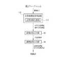
上記課題を解決するため、本発明の撮像素子の位置調整方法は、合焦座標値取得工程、結像面算出工程、調整値算出工程、調整工程を備えている。合状座標値取得工程は、測定チャートに直交するZ軸上に撮影レンズと撮影レンズによって結像されるチャート像を撮像する撮像素子とをセットし、Z軸上に予め離散的に設定された複数の測定位置に撮影レンズまたは撮像素子のいずれかを順次に移動して撮像を行っている。次いで、撮像素子の撮像面上に設定された少なくとも5つの撮像位置から得られる撮像信号に基づいて各々の撮像位置での合焦度合を表す個別の合焦評価値を複数の測定位置ごとに算出し、撮像位置の各々について、予め決められた指定値と複数の測定位置ごとに算出した各合焦評価値との差分をそれぞれ算出し、差分が最小となる測定位置のZ軸上の位置を合焦座標値としている。これによれば、各撮像位置の合焦評価値をバランスよく揃えることができるので、画質を向上させることができる。In order to solve the above-described problem, the image sensor position adjustment method of the present invention includes an in-focus coordinate value acquisition step, an imaging plane calculation step, an adjustment value calculation step, and an adjustment step. In the coordinate coordinate value acquisition step, a photographing lens and an image pickup device that captures a chart image formed by the photographing lens are set on the Z axis orthogonal to the measurement chart, and are set discretely on the Z axis in advance. Imaging is performed by sequentially moving either the photographing lens or the imaging element to a plurality of measurement positions. Next, based on imaging signals obtained from at least five imaging positions set on the imaging surface of the imaging element, individual focusing evaluation values representing the degree of focusing at each imaging position are calculated for each of a plurality of measurement positions. Then,for each of theimaging positions, a difference between a predetermined designated value and each focus evaluation value calculated for each of the plurality of measurement positions is calculated, and the position on the Z-axis of themeasurement position where the difference is minimum is calculated. The in-focus coordinate value is used.According to this, since the focus evaluation values at the respective imaging positions can be aligned with good balance, the image quality can be improved.
結像面算出工程は、撮像面をZ軸に直交するXY座標平面に対応させたときの各撮像位置のXY座標値と、それぞれの撮像位置ごとに得られたZ軸上の合焦座標値との組み合わせで表される少なくとも5つの評価点をXY座標平面とZ軸とを組み合わせた三次元座標系に展開したときに、これらの評価点の相対位置に基づいて三次元座標系で一平面として表される近似結像面を算出している。調整値算出工程は、Z軸と近似結像面との交点である結像面座標値と、XY座標平面に対する近似結像面のX軸及びY軸回りの回転角度とを算出している。調整工程は、結像面座標値及び回転角度に基づいて撮像素子のZ軸上での位置とX軸及びY軸回りの傾きとを調整し、撮像面を近似結像面に一致させている。 The imaging plane calculation step includes an XY coordinate value of each imaging position when the imaging plane is made to correspond to an XY coordinate plane orthogonal to the Z axis, and a focus coordinate value on the Z axis obtained for each imaging position. When at least five evaluation points represented by the combination are expanded into a three-dimensional coordinate system combining the XY coordinate plane and the Z axis, one plane in the three-dimensional coordinate system is based on the relative position of these evaluation points. The approximate imaging plane expressed as In the adjustment value calculating step, an image plane coordinate value that is an intersection of the Z axis and the approximate image plane, and a rotation angle about the X axis and the Y axis of the approximate image plane with respect to the XY coordinate plane are calculated. The adjustment step adjusts the position of the image sensor on the Z axis and the inclination around the X axis and the Y axis based on the image plane coordinate value and the rotation angle, so that the image plane coincides with the approximate image plane. .
合焦評価値として、コントラスト伝達関数値を用いるのが好ましい。また、合焦座標値取得工程では、撮像位置の各々について、複数の測定位置ごとに、XY座標平面上に設定された第1方向とこの第1方向に直交する第2方向のそれぞれについてコントラスト伝達関数値を算出し、かつ撮像位置の各々について、第1方向及び第2方向ごとに個別の第1合焦座標値及び第2合焦座標値を取得してもよい。結像面算出工程では、各撮像位置の第1合焦座標値及び第2合焦座標値から少なくとも10点の評価点を求め、これらの評価点の相対位置に基づいて近似結像面を算出するのが好ましい。これによれば、各撮像位置において、複数方向でのコントラスト伝達関数値にバラツキがある場合でもバランスのよい近似結像面を得ることができる。また、評価点の増加により、近似結像面の算出精度も向上する。 It is preferable to use a contrast transfer function value as the focus evaluation value. Further, in the in-focus coordinate value acquisition step, for each of the imaging positions, contrast transmission is performed for each of a plurality of measurement positions in a first direction set on the XY coordinate plane and a second direction orthogonal to the first direction. A function value may be calculated, and for each of the imaging positions, a separate first focus coordinate value and second focus coordinate value may be acquired for each of the first direction and the second direction. In the imaging plane calculation step, at least 10 evaluation points are obtained from the first focusing coordinate value and the second focusing coordinate value at each imaging position, and an approximate imaging plane is calculated based on the relative positions of these evaluation points. It is preferable to do this. According to this, even when there are variations in the contrast transfer function values in a plurality of directions at each imaging position, an approximate imaging plane with a good balance can be obtained. Also, the accuracy of calculating the approximate imaging plane is improved by increasing the evaluation points.
コントラスト伝達関数値が算出される第1方向及び第2方向として、水平方向及び垂直方向が好ましい。また、撮影レンズの径方向及びこの径方向に直交する直交方向で、コントラスト伝達関数値を求めてもよい。 The first direction and the second direction in which the contrast transfer function value is calculated are preferably the horizontal direction and the vertical direction. Further, the contrast transfer function value may be obtained in the radial direction of the photographing lens and the orthogonal direction orthogonal to the radial direction.
撮像面上に設定した5つの撮像位置は、例えば、撮像面の中心と、撮像面の4象限上とに1つずつ設定することが好ましい。また、合焦座標値取得工程において、撮像位置の各々に結像されるチャートパターンは、同一であることが好ましい。 The five imaging positions set on the imaging surface are preferably set one by one, for example, in the center of the imaging surface and in the four quadrants of the imaging surface. In the in-focus coordinate value acquisition step, it is preferable that the chart patterns formed at each imaging position are the same.
調整工程の後に合焦座標値取得工程を行い、撮像位置の各々について、合焦座標値を確認してもよい。また、合焦座標値取得工程、結像面算出工程、調整値算出工程、調整工程を複数回繰り返して、撮像面を近似結像面に一致させてもよい。これによれば、調整精度が向上する。 A focus coordinate value acquisition process may be performed after the adjustment process, and the focus coordinate value may be confirmed for each of the imaging positions. Further, the in-focus coordinate value acquisition step, the imaging plane calculation step, the adjustment value calculation step, and the adjustment step may be repeated a plurality of times so that the imaging plane coincides with the approximate imaging plane. According to this, the adjustment accuracy is improved.
本発明のカメラモジュール製造方法は、上記撮像素子の位置調整方法を用いて、素子ユニットの位置調整を行っている。 In the camera module manufacturing method of the present invention, the position adjustment of the element unit is performed using the position adjustment method of the image pickup element.
本発明のカメラモジュール製造装置は、測定チャート、レンズユニット保持手段、素子ユニット保持手段、移動手段、素子制御手段、合焦座標値取得手段、結像面算出手段、調整値算出手段、調整手段を備えている。測定チャートには、撮像素子により撮像されるチャートパターンが設けられている。レンズユニット保持手段は、撮影レンズを組み込んだレンズユニットを保持し、測定チャートに直交するZ軸上にセットしている。素子ユニット保持手段は、撮像素子を組み込んだ素子ユニットを保持してZ軸上にセットするとともに、素子ユニットのZ軸上での位置と、Z軸に直交するX軸及びY軸回りの傾きとを変化させることができる。測定位置移動手段は、Z軸上に予め離散的に設定された複数の測定位置に、撮影レンズまたは撮像素子が順次に移動されるように、レンズユニット保持手段または素子ユニット保持手段のいずれかを移動する。素子制御手段は、測定位置の各々で、撮像素子に撮影レンズにより結像されたチャート像を撮像させる。 The camera module manufacturing apparatus of the present invention includes a measurement chart, a lens unit holding unit, an element unit holding unit, a moving unit, an element control unit, an in-focus coordinate value acquisition unit, an imaging plane calculation unit, an adjustment value calculation unit, and an adjustment unit. I have. The measurement chart is provided with a chart pattern imaged by the image sensor. The lens unit holding unit holds the lens unit in which the photographing lens is incorporated and is set on the Z axis orthogonal to the measurement chart. The element unit holding means holds the element unit in which the imaging element is incorporated and sets it on the Z axis, and the position of the element unit on the Z axis and the inclination around the X axis and the Y axis perpendicular to the Z axis. Can be changed. The measurement position moving means includes either the lens unit holding means or the element unit holding means so that the photographing lens or the imaging element is sequentially moved to a plurality of measurement positions discretely set in advance on the Z axis. Moving. The element control means causes the image pickup element to pick up a chart image formed by the photographing lens at each measurement position.
合焦座標値取得手段は、撮像素子の撮像面上に設定された少なくとも5つの撮像位置から得られる撮像信号に基づいて各々の撮像位置での合焦度合を表す個別の合焦評価値を複数の測定位置ごとに算出し、撮像位置の各々について、予め決められた指定値と複数の測定位置ごとに算出した各合焦評価値との差分をそれぞれ算出し、差分が最小となる測定位置のZ軸上の位置を合焦座標値としている。結像面算出手段は、撮像面をZ軸に直交するXY座標平面に対応させたときの各撮像位置のXY座標値と、それぞれの撮像位置ごとに得られたZ軸上の合焦座標値との組み合わせで表される少なくとも5つの評価点をXY座標平面とZ軸とを組み合わせた三次元座標系に展開したときに、これらの評価点の相対位置に基づいて三次元座標系で一平面として表される近似結像面を算出している。The in-focus coordinate value acquisition unit is configured to obtain a plurality of individual in-focus evaluation values representing the in-focus degree at each imaging position based on imaging signals obtained from at least five imaging positions set on the imaging surface of the imaging element.For each imaging position, and for each of theimaging positions , calculate a differencebetween a predetermined value determined in advance and each focus evaluation value calculated for each of the plurality of measurement positions . The position on the Z axis is the in-focus coordinate value. The imaging plane calculation means calculates the XY coordinate value of each imaging position when the imaging plane is made to correspond to the XY coordinate plane orthogonal to the Z axis, and the in-focus coordinate value on the Z axis obtained for each imaging position. When at least five evaluation points represented by the combination are expanded into a three-dimensional coordinate system combining the XY coordinate plane and the Z axis, one plane in the three-dimensional coordinate system is based on the relative position of these evaluation points. The approximate imaging plane expressed as
調整値算出手段は、Z軸と近似結像面との交点である結像面座標値と、XY座標平面に対する近似結像面のX軸及びY軸回りの回転角度とを算出している。調整手段は、結像面座標値及び回転角度に基づいて素子ユニット保持手段を駆動させ、撮像素子のZ軸上での位置とX軸及びY軸回りの傾きとを調整し、撮像面を近似結像面に一致させている。 The adjustment value calculating means calculates an image plane coordinate value that is an intersection of the Z axis and the approximate image plane, and a rotation angle about the X axis and the Y axis of the approximate image plane with respect to the XY coordinate plane. The adjustment unit drives the element unit holding unit based on the image plane coordinate value and the rotation angle, adjusts the position of the image sensor on the Z axis and the inclination about the X axis and the Y axis, and approximates the image plane. It coincides with the image plane.
カメラモジュール製造装置には、素子ユニットのZ軸上での位置と、Z軸に直交するX軸及びY軸回りの傾きとの調整後に、レンズユニットと素子ユニットとを固定させる固定手段を備えてもよい。 The camera module manufacturing apparatus includes a fixing unit that fixes the lens unit and the element unit after adjusting the position of the element unit on the Z axis and the inclination about the X axis and the Y axis orthogonal to the Z axis. Also good.
素子ユニット保持手段は、素子ユニットを保持する保持機構と、保持機構をX軸及びY軸回りで傾ける2軸回転ステージと、2軸回転ステージをZ軸方向に沿って移動させるスライドステージとから構成している。 The element unit holding means includes a holding mechanism that holds the element unit, a biaxial rotary stage that tilts the holding mechanism about the X axis and the Y axis, and a slide stage that moves the biaxial rotary stage along the Z axis direction. doing.
素子ユニット保持手段には、撮像素子と素子制御手段とを電気的に接続させる素子接続部を設けてもよい。また、レンズユニット保持手段には、レンズユニット内に組み込まれたオートフォーカス機構と、このオートフォーカス機構を駆動するAFドライバとを電気的に接続させるAF接続部を設けてもよい。 The element unit holding means may be provided with an element connecting portion for electrically connecting the image pickup element and the element control means. In addition, the lens unit holding means may be provided with an AF connection portion that electrically connects an autofocus mechanism incorporated in the lens unit and an AF driver that drives the autofocus mechanism.
チャートパターンは、矩形のチャート面をその中心位置に対してX軸方向、Y軸方向及び2つの対角線方向に沿って分割した8つの領域を有し、第1〜第4象限のそれぞれに設けられた2つの領域内に、互いに直交する平行な複数本の線が設けてもよい。これによれば、測定チャートを取り替えることなく、画角の異なる撮像素子を用いたカメラモジュールの製造にも用いることができる。 The chart pattern has eight regions obtained by dividing a rectangular chart surface along the X axis direction, the Y axis direction, and two diagonal directions with respect to the center position, and is provided in each of the first to fourth quadrants. Further, a plurality of parallel lines orthogonal to each other may be provided in the two regions. According to this, it can use also for manufacture of the camera module using the image pick-up element from which an angle of view changes, without replacing a measurement chart.
本発明のカメラモジュールに用いる素子ユニットは、次のような手順で位置調整が行われている。まず、測定チャートに直交するZ軸上にレンズユニットと素子ユニットとをセットし、Z軸上に予め離散的に設定された複数の測定位置に撮影レンズまたは撮像素子が停止されるように、レンズユニットまたは素子ユニットのいずれかを順次に移動して撮像を行い、撮像素子の撮像面上に設定された少なくとも5つの撮像位置から得られる撮像信号に基づいて各々の撮像位置での合焦度合を表す個別の合焦評価値を複数の測定位置ごとに算出し、撮像位置の各々について、予め決められた指定値と複数の測定位置ごとに算出した各合焦評価値との差分をそれぞれ算出し、差分が最小となる測定位置撮像位置の各々について所定の合焦評価値が得られたときのそれぞれのZ軸上の位置を合焦座標値としている。The position of the element unit used in the camera module of the present invention is adjusted in the following procedure. First, the lens unit and the element unit are set on the Z axis orthogonal to the measurement chart, and the photographing lens or the imaging element is stopped at a plurality of measurement positions set in advance discretely on the Z axis. The unit or the element unit is sequentially moved to perform imaging, and the degree of focus at each imaging position is determined based on imaging signals obtained from at least five imaging positions set on the imaging surface of the imaging element. An individual focus evaluation value is calculated for each of a plurality of measurement positions, and for each of theimaging positions, a difference between a predetermined specified value and each focus evaluation value calculated for each of the plurality of measurement positions is calculated. The position on the Z axis when a predetermined focus evaluation value is obtained for each of themeasurement position imaging positionswhere the difference is minimum is used as the focus coordinate value.
ついで、撮像面をZ軸に直交するXY座標平面に対応させたときの各撮像位置のXY座標値と、それぞれの撮像位置ごとに得られたZ軸上の合焦座標値との組み合わせで表される少なくとも5つの評価点をXY座標平面とZ軸とを組み合わせた三次元座標系に展開したときに、これらの評価点の相対位置に基づいて三次元座標系で一平面として表される近似結像面を算出している。Z軸と近似結像面との交点である結像面座標値と、XY座標平面に対する近似結像面のX軸及びY軸回りの回転角度とを算出し、さらに、結像面座標値及び回転角度に基づいて、撮像面が近似結像面に一致するように、前記撮像素子のZ軸上での位置とX軸及びY軸回りの傾きとが調整されている。 Next, it is expressed by a combination of the XY coordinate value of each imaging position when the imaging surface is made to correspond to the XY coordinate plane orthogonal to the Z axis and the in-focus coordinate value on the Z axis obtained for each imaging position. When at least five evaluation points are expanded into a three-dimensional coordinate system combining the XY coordinate plane and the Z axis, an approximation represented as a single plane in the three-dimensional coordinate system based on the relative positions of these evaluation points The image plane is calculated. An imaging plane coordinate value that is an intersection of the Z axis and the approximate imaging plane, and a rotation angle about the X axis and the Y axis of the approximate imaging plane with respect to the XY coordinate plane are calculated. Based on the rotation angle, the position of the image sensor on the Z-axis and the inclination about the X-axis and the Y-axis are adjusted so that the image-capturing surface coincides with the approximate imaging plane.
本発明によれば、撮像素子の撮像面上に設定された各撮像位置の合焦座標値の取得、各合焦座標値からの近似結像面の算出、撮像面を近似結像面に一致させるための調整値の算出、撮像面を近似結像面に一致させる調整を自動的に行うことができ、さらには調整工程では、フォーカス調整とあおり調整とが同時に行われるので、短時間で撮像素子の位置調整を完了させることができる。よって、本発明を量産型カメラモジュールの製造に適用したときの効果は非常に大きく、一定品質以上のカメラモジュールを短時間で大量に生産することができる。 According to the present invention, the in-focus coordinate value of each imaging position set on the imaging surface of the image sensor is obtained, the approximate imaging plane is calculated from each in-focus coordinate value, and the imaging plane is matched with the approximate imaging plane. Adjustment value for adjusting the image and adjusting the imaging surface to the approximate imaging surface can be automatically performed.Furthermore, in the adjustment process, focus adjustment and tilt adjustment are performed at the same time. The position adjustment of the element can be completed. Therefore, the effect when the present invention is applied to the production of a mass-produced camera module is very large, and camera modules with a certain quality or higher can be produced in a large amount in a short time.
図1、2に示すカメラモジュール2は、例えば、1辺が10mm角程度のサイズを有する立方形状である。カメラモジュール2の前面中央には、撮影開口5が形成されている。撮影開口5の奥には、撮影レンズ6が配置されている。撮影開口5の周囲の対角線上には、カメラモジュール2の製造時の位置決めに用いられる3つないしは4つの位置決め面7〜9が設けられている。この位置決め面7〜9のうち、同じ対角線上に位置する2つの位置決め面7、9の略中央には、位置決め面よりも小径の位置決め穴7a,9aが形成されている。これにより、空間上の絶対位置及び傾きを高精度に規制する。 The
カメラモジュール2の背面には、矩形の開口11が形成されている。この開口11は、内蔵されている撮像素子12の背面に設けられた複数の接点13を露出させている。 A
図3に示すように、カメラモジュール2は、撮影レンズ6が組み込まれたレンズユニット15と、撮像素子12が組み込まれた素子ユニット16から構成されている。素子ユニット16は、レンズユニット15の背面側に取り付けられている。 As shown in FIG. 3, the
図4に示すように、レンズユニット15は、略筒状に形成されたユニット本体19と、このユニット本体19内に組み込まれたレンズ鏡筒20と、ユニット本体19の前面側に固着される前カバー21から構成されている。前カバー21には、上述した撮影開口5、位置決め面7〜9等が設けられている。ユニット本体19、レンズ鏡筒20、前カバー21は、例えばプラスチックで形成されている。 As shown in FIG. 4, the
レンズ鏡筒20は、円筒状に形成されており、例えば3群構成の撮影レンズ6が組み込まれている。レンズ鏡筒20は、ユニット本体19の前面に取り付けられた金属製の板バネ24に保持されており、板バネ24の弾性によって光軸S方向に移動自在となっている。 The
レンズ鏡筒20の外周とユニット本体19の内周には、互いに対峙するように永久磁石25と電磁石26とが取り付けられ、オートフォーカス機能を実現している。電磁石26は、供給される電流の向きが切り換えられることにより極性が変化する。レンズ鏡筒20は、永久磁石25が電磁石26の極性変化に応じて反発または吸引されることにより、光軸S方向に移動してフォーカスを調整している。電磁石26に電流を供給する接点26aは、例えば、ユニット本体19の下面から露出するように設けられている。なお、オートフォーカス機能に用いる機構としては、パルスモータ+送りネジ、ピエゾ振動子による送り機構等も考えられる。 A
素子ユニット16は、矩形の枠状に形成された素子枠29と、撮像面12aがレンズユニット15側を向くように素子枠29内に取り付けられた撮像素子12から構成されている。素子枠29は、例えばプラスチックで形成されている。 The element unit 16 includes an
素子枠29の前面側方と、ユニット本体19の側面及び背面の間の角部には、4つの嵌合片32と、これらの嵌合片32が嵌合される凹状の嵌合部33がそれぞれ設けられている。これらの嵌合片32及び嵌合部33の勘合後に、嵌合部33内に接着剤が充填されることで、レンズユニット15と素子ユニット16とが固着される。 Four
ユニット本体19の両側面の背面側角部には、高さ位置の異なる一対の切欠36が設けられている。また、素子枠29の両側面には、一対の平面部37が設けられている。切欠36及び平面部37は、レンズユニット15と素子ユニット16との組立時に、両者を位置決めして保持するために用いられる。なお、切欠36及び平面部37を設けているのは、ユニット本体19及び素子枠29が射出成形により形成され、側面が型抜きのための緩やかなテーパー形状とされるためであり、テーパーの無い面を保持する場合には、設けなくてもよい。 A pair of
次に、本発明のカメラモジュール製造装置の第1実施形態について説明する。図5に示すカメラモジュール製造装置は、上記レンズユニット15に対する素子ユニット16の位置を調整し、調整後に素子ユニット16をレンズユニット15に固定する。カメラモジュール製造装置40は、例えば、チャートユニット41と、集光ユニット42と、レンズ位置決めプレート43と、レンズ保持機構44と、素子移動機構45と、接着剤供給器46と、紫外線ランプ47と、これらを制御する制御部48から構成されている。これらは、共通の作業台49上に設置されている。 Next, a first embodiment of the camera module manufacturing apparatus of the present invention will be described. The camera module manufacturing apparatus shown in FIG. 5 adjusts the position of the element unit 16 with respect to the
チャートユニット41は、箱状の筐体41aと、筐体41a内に嵌合される測定チャート52と、筐体41a内に組み込まれて測定チャート52を背面から平行光で照明する光源53とから構成されている。測定チャート52は、例えば、光拡散性を有するプラスチック板で形成されている。 The
図6に示すように、測定チャート52は矩形状であり、チャートパターンが設けられたチャート面には、中心52aと、4象限上の左上、左下、右上、右下とに第1〜第5チャート画像56〜60がそれぞれ印刷されている。第1〜第5チャート画像56〜60は、全て同一の画像であり、黒色の線を所定間隔で配列させた、いわゆるラダー状のチャートパターンであり、それぞれ水平方向に配列させた水平チャート画像56a〜60aと、垂直方向に配列させた垂直チャート画像56b〜60bから構成されている。 As shown in FIG. 6, the
集光ユニット42は、測定チャート52の中心52aに直交するZ軸上において、チャートユニット41に対面するように配置されている。集光ユニット42は、作業台49に固定されたブラケット42aと、集光レンズ42bから構成されている。集光レンズ42bは、チャートユニット41から放射された光を集光し、ブラケット42aに形成された開口42cを通してレンズユニット15に入射させる。 The condensing
レンズ位置決めプレート43は、例えば金属によって剛性を有するように形成されており、集光ユニット42により集光された光を通過させる開口43aが設けられている。 The
図7に示すように、レンズ位置決めプレート43のレンズ保持機構44に対する面には、開口43aの周囲に3個の当接ピン63〜65が設けられている。3個の当接ピン63〜65のうち、対角線上に配置された2個の当接ピン63、65の先端には、当接ピンよりも小径の挿入ピン63a,65aが設けられている。当接ピン63〜65は、レンズユニット15の位置決め面7〜9を受け、挿入ピン63a,65aは、位置決め穴7a,9aに挿入されてレンズユニット15を位置決めする。 As shown in FIG. 7, on the surface of the
レンズ保持機構44は、Z軸上でチャートユニット41に前面が向くようにレンズユニット15を保持する保持プレート68と、この保持プレート68をZ軸方向に移動させる第1スライドステージ69とから構成されている。図7に示すように、保持プレート68は、第1スライドステージ69のステージ部69aに保持される水平基部68aと、この水平基部68aから上方及び水平方向に突設されてレンズユニット15の一対の切欠36に嵌合される一対の保持アーム68bとを備えている。 The lens holding mechanism 44 includes a holding
保持プレート68には、電磁石26の接点26aに接触する複数のプローブピン70aを備えた第1プローブユニット70が取り付けられている。この第1プローブユニット70は、電磁石26と、AFドライバ84(図8参照)とを電気的に接続する。 A
第1スライドステージ69は、いわゆる自動精密ステージと呼ばれるもので、図示しないモータの回転によってボールネジを回転させ、このボールネジに噛合されたステージ部69aを水平に移動させる。 The
素子移動機構45は、Z軸上でチャートユニット41に撮像面12aが向くように素子ユニット16を保持するチャックハンド72と、チャックハンド72が取り付けられた略クランク状のブラケット73を保持してZ軸に直交する2軸の回りで傾きを調整する2軸回転ステージ74と、2軸回転ステージ74が取り付けられたブラケット75を保持してZ軸方向に移動させる第2スライドステージ76とから構成されている。 The element moving mechanism 45 holds a
チャックハンド72は、図7に示すように、略クランク状に屈曲された一対の挟持部材72aと、これらの挟持部材72aをZ軸に直交するX軸方向で移動させるアクチュエータ72bとから構成されている。挟持部材72aは、素子枠29の平面部37を挟み込んで素子ユニット16を保持する。また、チャックハンド72は、撮影レンズ6の光軸中心と撮像面12aの中心12bとが略一致するように、挟持部材72aに挟持された素子ユニット16を位置決めする。 As shown in FIG. 7, the
2軸回転ステージ74は、いわゆる自動2軸ゴニオステージと呼ばれるもので、図示しない2つのモータの回転により、撮像面12aの中心12bを中心にして、素子ユニット16をX軸の回りのθX方向と、Z軸及びX軸に直交するY軸の回りのθY方向で傾ける。これにより、素子ユニット16を各方向に傾けた際に、撮像面12aの中心12bとZ軸との位置関係がずれることがない。 The biaxial
第2スライドステージ76は、本発明の測定位置移動手段を兼用しており、2軸回転ステージ74を介して素子ユニット16をZ軸方向に移動させる。なお、第2スライドステージ76は、第1スライドステージ69とサイズ等が異なる以外はほぼ同様のものなので、詳しい説明は省略する。 The
2軸回転ステージ74には、素子ユニット16の開口11を通して撮像素子12の各接点13に接触する複数のプローブピン79aを備えた第2プローブユニット79が取り付けられている。この第2プローブユニット79は、撮像素子12と撮像素子ドライバ85(図8参照)とを電気的に接続する。 A
接着剤供給器46は、素子ユニット16の位置調整が終了してレンズユニット15の嵌合部33に素子ユニット16の嵌合片32が嵌合されたときに、嵌合部33内に紫外線硬化接着剤を供給する。接着剤供給器46とともに固定手段を構成する紫外線ランプ47は、嵌合部33に紫外線を照射して紫外線硬化接着剤を硬化させる。なお、接着剤としては、瞬間接着剤、熱硬化接着剤、自然硬化接着剤等も利用可能である。 When the position adjustment of the element unit 16 is completed and the
図8に示すように、上で説明した各部は制御部48に接続されている。制御部48は、例えば、CPUやROM、RAM等を備えたマイクロコンピュータであり、ROMに記憶されている制御プログラムに基づいて各部を制御している。また、制御部48には、各種設定を行うキーボードやマウス等の入力装置81と、設定内容や作業内容、作業結果等が表示されるモニタ82とが接続されている。 As illustrated in FIG. 8, each unit described above is connected to the
AFドライバ84は、電磁石26を駆動する駆動回路であり、第1プローブユニット70を介して電磁石26に電流を流している。撮像素子ドライバ85は、撮像素子12を駆動する駆動回路であり、第2プローブユニット79を介して撮像素子12に制御信号を入力している。 The
合焦座標値取得回路87は、図9に示す撮像素子12の撮像面12a上に設定された第1〜第5撮像位置89a〜89eのZ軸方向において、合焦度合の高い位置である合焦座標値を取得する。第1〜第5撮像位置89a〜89eは、撮像面12aの中心12bと、4象限上の左上、左下、右上、右下とに設定されており、測定チャート52の第1〜第5チャート画像56〜60が撮像可能な位置及び範囲をそれぞれ有している。なお、測定チャート52は、撮影レンズ6により上下左右が反転して結像されるので、第2〜第5撮像位置89b〜89eは、それぞれ対角線上の反対側に配置された第2〜第5チャート画像57〜60を撮像する。 The in-focus coordinate
制御部48は、第1〜第5撮像位置89a〜89eの合焦座標値を取得する際に、第2スライドステージ76を制御し、Z軸上に予め離散的に設定された複数の測定位置に素子ユニット16を順次に移動させる。また、制御部48は、撮像素子ドライバ85を制御し、各測定位置で撮影レンズ6が結像した第1〜第5チャート画像56〜60のチャート像を撮像素子12に撮像させる。 The
合焦座標値取得回路87は、第2プローブユニット79を介して入力された撮像信号から第1〜第5撮像位置89a〜89eに対応する画素の信号を抽出し、その画素信号から第1〜第5撮像位置89a〜89eについて個別の合焦評価値を複数の測定位置ごとに算出し、第1〜第5撮像位置89a〜89eの各々について所定の合焦評価値が得られたときの測定位置をZ軸上の合焦座標値としている。 The focused coordinate
本実施形態では、合焦評価値として、コントラスト伝達関数値(Contrast Transfer Function:以下、CTF値と呼ぶ)を用いている。CTF値は、空間周波数に対する像のコントラストを表す値であり、CTF値が高いときに合焦しているとみなすことができる。CTF値は、撮像素子12から出力された撮像信号の出力値の最大値と最小値との差を、出力値の最大値と最小値との和で除して求められる。例えば撮像信号の出力値の最大値をPとし、最小値をQとしたとき、CTF値は、以下の式(1)によって算出される。
CTF値=(P−Q)/(P+Q)・・・(1)In the present embodiment, a contrast transfer function value (hereinafter referred to as a CTF value) is used as the focus evaluation value. The CTF value is a value representing the contrast of the image with respect to the spatial frequency, and can be regarded as being in focus when the CTF value is high. The CTF value is obtained by dividing the difference between the maximum value and the minimum value of the output value of the imaging signal output from the
CTF value = (P−Q) / (P + Q) (1)
合焦座標値取得回路87は、第1〜第5撮像位置89a〜89eの各々について、Z軸上に設定された複数の測定位置ごとに、XY座標平面上で設定した複数方向のそれぞれに対してCTF値を算出している。CTF値が算出される方向としては、任意の第1方向とこの第1方向に直交する第2方向であり、例えば本実施形態では、撮像面12aの横方向である水平方向(X軸方向)と、これに直交する垂直方向(Y軸方向)のCTF値であるH−CTF値及びV−CTF値をそれぞれ算出する。また、合焦座標値取得回路87は、第1〜第5撮像位置89a〜89eの各々について、H−CTF値及びV−CTF値が最大となる測定位置のZ軸上の座標を水平合焦座標値及び垂直合焦座標値として取得する。 The in-focus coordinate
結像面算出回路92には、合焦座標値取得回路87から第1〜第5撮像位置89a〜89eの水平合焦座標値及び垂直合焦座標値が入力される。結像面算出回路92は、撮像面12aをXY座標平面に対応させたときの各撮像位置89a〜89eのXY座標値と、それぞれの撮像位置89a〜89eごとに得られたZ軸上の水平合焦座標値及び垂直合焦座標値との組み合わせで表される10点の評価点を、XY座標平面とZ軸とを組み合わせた三次元座標系に展開し、これらの評価点の相対位置に基づいて三次元座標系で一平面として表される近似結像面を算出する。 The imaging plane calculation circuit 92 receives the horizontal focus coordinate values and the vertical focus coordinate values of the first to fifth imaging positions 89a to 89e from the focus coordinate
結像面算出回路92による近似結像面の算出には、例えば、aX+bY+cZ+d=0の式(a〜dは任意の定数)で表される最小自乗法が用いられている。結像面算出回路92は、第1〜第5撮像位置89a〜89eのXY座標平面上の座標値と、合焦座標値取得回路87により求められたZ軸上の水平合焦座標値または垂直合焦座標値とを上記式に代入して演算することにより、近似結像面を算出する。 For the calculation of the approximate imaging plane by the imaging plane calculation circuit 92, for example, a least square method represented by an expression aX + bY + cZ + d = 0 (a to d are arbitrary constants) is used. The imaging plane calculation circuit 92 has the coordinate values on the XY coordinate plane of the first to fifth imaging positions 89a to 89e and the horizontal focus coordinate value on the Z axis obtained by the focus coordinate
調整値算出回路95には、結像面算出回路92から近似結像面の情報が入力される。調整値算出回路95は、近似結像面とZ軸との交点であるZ軸上の結像面座標値と、XY座標平面に対する近似結像面のX軸回り及びY軸回りの傾きであるXY方向回転角度とを算出し、制御部48に入力する。制御部48は、調整値算出回路95から入力された結像面座標値及びXY方向回転角度に基づいて素子移動機構45を駆動させ、撮像面12aが近似結像面に一致するように素子ユニット16の位置及び姿勢を調整する。 Information about the approximate image plane is input from the image plane calculation circuit 92 to the adjustment value calculation circuit 95. The adjustment value calculation circuit 95 is an image plane coordinate value on the Z axis that is an intersection of the approximate image plane and the Z axis, and an inclination about the X axis and the Y axis of the approximate image plane with respect to the XY coordinate plane. The XY direction rotation angle is calculated and input to the
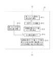
次に、上記実施形態の作用について、図10及び11のフローチャートを参照しながら説明する。まず、レンズ保持機構44によるレンズユニット15の保持(S1)について説明する。制御部48は、第1スライドステージ69を制御して保持プレート68を移動させることにより、レンズ位置決めプレート43と保持プレート68との間にレンズユニット15が挿入可能なスペースを形成している。レンズユニット15は、図示しないロボットにより保持されて、レンズ位置決めプレート43と保持プレート68との間に移動される。 Next, the operation of the above embodiment will be described with reference to the flowcharts of FIGS. First, the holding (S1) of the
制御部48は、光学センサ等でレンズユニット15の移動を検知し、第1スライドステージ69のステージ部69aをレンズ位置決めプレート43に近付ける方向に移動させる。保持プレート68は、一対の保持アーム68bを一対の切欠36に嵌合させてレンズユニット15を保持する。第1プローブユニット70は、接点26aに接触して電磁石26と、AFドライバ84とを電気的に接続する。 The
図示しないロボットによるレンズユニット15の保持解除後、保持プレート68は更にレンズ位置決めプレート43に向けて移動され、位置決め面7〜9が当接ピン63〜65に当接し、位置決め穴7a,9aに挿入ピン63a,65aが挿入される。これにより、レンズユニット15は、Z軸方向と、X軸方向及びY軸方向とで位置決めされる。なお、位置決め面7〜9及び当接ピン63〜65は3個ずつしか設けられておらず、位置決め穴7a,9a及び挿入ピン63a,65aは対角線上に2個しか設けられていないので、レンズユニット15が誤ってセットされることはない。 After the holding of the
次に、素子移動機構45による素子ユニット16の保持(S2)について説明する。制御部48は、第2スライドステージ76を制御して2軸回転ステージ74を移動させることにより、保持プレート68と2軸回転ステージ74との間に素子ユニット16が挿入可能なスペースを形成している。素子ユニット16は、図示しないロボットにより保持されて、保持プレート68と2軸回転ステージ74との間に移動される。 Next, the holding (S2) of the element unit 16 by the element moving mechanism 45 will be described. The
制御部48は、光学センサ等で素子ユニット16の移動を検知し、第2スライドステージ76のステージ部76aを保持プレート68に近付ける方向に移動させる。そして、チャックハンド72の挟持部材72aにより、平面部37を挟み込ませて素子ユニット16を保持させる。また、第2プローブユニット79の各プローブ79aが撮像素子12の各接点13に接触され、撮像素子12と制御部48とが電気的に接続される。その後、図示しないロボットによる素子ユニット16の保持が解除される。 The
レンズユニット15及び素子ユニット16の保持完了後、撮像面12aの第1〜第5撮像位置89a〜89eの水平合焦座標値及び垂直合焦座標値が取得される(S3)。図11に示すように、制御部48は、第2スライドステージ76を制御して2軸回転ステージ74をレンズ保持機構44に近づく方向に移動させ、撮像素子12がレンズユニット15に最も近くなる最初の測定位置に素子ユニット16を移動させる(S3−1)。 After the holding of the
制御部48は、チャートユニット41の光源53を発光させる。また、制御部48は、AFドライバ84を制御して、撮影レンズ6を所定の焦点位置に移動させ、撮像素子ドライバ85を制御して、撮影レンズ6が結像した第1〜第5チャート画像56〜60を撮像素子12に撮像させる(S3−2)。撮像素子12から出力された撮像信号は、第2プローブユニット79を介して合焦座標値取得回路87に入力される。 The
合焦座標値取得回路87は、入力された撮像信号から第1〜第5撮像位置89a〜89eに対応する画素の信号を抽出し、その画素信号から第1〜第5撮像位置89a〜89eについてのH−CTF値及びV−CTF値を算出する(S3−3)。H−CTF値及びV−CTF値は、例えば、制御部48内のRAMに記憶される。 The focused coordinate
制御部48は、素子ユニット16をZ軸方向に沿って設定された複数の測定位置に順次に移動させ、各測定位置で撮像素子12に測定チャート52のチャート像を撮像させる。合焦座標値取得回路87は、各測定位置で第1〜第5撮像位置89a〜89eのH−CTF値及びV−CTF値を算出する(S3−2〜S3−4)。 The
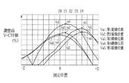
図12、13のグラフは、第1〜第5撮像位置89a〜89eの各測定位置におけるH−CTF値であるHa1〜Ha5と、V−CTF値であるVa1〜Va5の算出結果の一例を示している。なお、測定位置「0」は、撮影レンズ6による設計上の結像面を表している。合焦座標値取得回路87は、第1〜第5撮像位置89a〜89eの各々について、算出された複数のH−CTF値Ha1〜Ha5、及びV−CTF値Va1〜Va5の中から最大値を選択し、最大値が得られた測定位置のZ軸座標を第1〜第5撮像位置89a〜89eの水平合焦座標値及び垂直合焦座標値として取得する(S3−6)。 The graphs of FIGS. 12 and 13 show an example of calculation results of Ha1 to Ha5 that are H-CTF values and Va1 to Va5 that are V-CTF values at the measurement positions of the first to fifth imaging positions 89a to 89e. ing. Note that the measurement position “0” represents the designed imaging plane by the photographing
図12、13に示す例では、H−CTF値ha1〜ha5、及びV−CTF値va1〜va5がそれぞれ最大値となっており、これらのCTF値に対応する測定位置Z0〜Z5及びZ0〜Z4のZ軸座標が、水平合焦座標値及び垂直合焦座標値として取得される。 In the example shown in FIGS. 12 and 13, the H-CTF values ha1 to ha5 and the V-CTF values va1 to va5 are the maximum values, respectively, and the measurement positions Z0 to Z5 and Z0 to Z4 corresponding to these CTF values. Are obtained as the horizontal focus coordinate value and the vertical focus coordinate value.
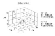
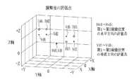
図14、15に示すグラフは、撮像面12aをXY座標平面に対応させたときの各撮像位置89a〜89eのXY座標値と、それぞれの撮像位置89a〜89eごとに得られたZ軸上の水平合焦座標値及び垂直合焦座標値との組み合わせで表される10個の評価点Hb1〜Hb5及びVb1〜Vb5を、XYZの三次元座標系に展開した状態を示している。これらのグラフから分るように、水平方向の評価点Hb1〜Hb5、及び垂直方向のVb1〜Vb5により表される撮像素子12の実際の結像面は、各部品の製造誤差、組立誤差により、Z軸の「0」上に形成される設計上の結像面に対してずれてしまう。 The graphs shown in FIGS. 14 and 15 show the XY coordinate values of the respective imaging positions 89a to 89e when the
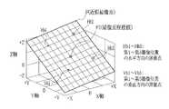
合焦座標値取得回路87において取得された水平合焦座標値及び垂直合焦座標値は、結像面算出回路92に入力される。結像面算出回路92は、最小自乗法により平面近似された近似結像面を算出する(S5)。図16及び17に示すように、結像面算出回路92により算出された近似結像面Fは、評価点Hb1〜Hb5及びVb1〜Vb5の相対位置に基づいてバランスよく設定されている。 The horizontal focus coordinate value and the vertical focus coordinate value acquired by the focus coordinate
結像面算出回路92で算出された近似結像面Fの情報は、調整値算出回路95に入力される。図16及び17に示すように、調整値算出回路95は、近似結像面FとZ軸との交点である結像面座標値F1と、XY座標平面に対する近似結像面のX軸回り及びY軸回りの傾きであるXY方向回転角度とを算出し、制御部48に入力する(S6)。 Information about the approximate image plane F calculated by the image plane calculation circuit 92 is input to the adjustment value calculation circuit 95. As shown in FIGS. 16 and 17, the adjustment value calculation circuit 95 includes an imaging plane coordinate value F1 that is an intersection of the approximate imaging plane F and the Z axis, the X axis of the approximate imaging plane with respect to the XY coordinate plane, The rotation angle in the XY direction, which is the inclination around the Y axis, is calculated and input to the control unit 48 (S6).
制御部48は、結像面座標値F1とXY方向回転角度に基づいて、2軸回転ステージ74及び第2スライドステージ76を制御し、撮像面12aの中心12aが結像面座標値F1に一致するように、素子ユニット16をZ軸方向に移動させ、撮像面12aの傾きが近似結像面Fに一致するように、素子ユニット16のθX方向及びθY方向の角度を調整させる(S7)。 The
素子ユニット16の位置調整後に、第1〜第5撮像位置89a〜89eの合焦位置を確認する確認工程が実施される(S8)。この確認工程では、上述したS3の各工程が再び実行される。 After the position adjustment of the element unit 16, a confirmation step for confirming the in-focus positions of the first to fifth imaging positions 89a to 89e is performed (S8). In this confirmation step, each step of S3 described above is executed again.
図18、19に示すグラフは、確認工程で算出された第1〜第5撮像位置89a〜89eの各測定位置におけるH−CTF値Hc1〜Hc5、及びV−CTF値Vc1〜Vc5の算出結果の一例を表している。このグラフから分るように、素子ユニット16の位置調整後には、CTF値の最大値であるH−CTF値hc1〜hc5及びV−CTF値vc1〜vc5が、それぞれ測定位置Z1〜Z4及びZ1〜Z3の間に収まるように収束される。 18 and 19 show the calculation results of the H-CTF values Hc1 to Hc5 and the V-CTF values Vc1 to Vc5 at the measurement positions of the first to fifth imaging positions 89a to 89e calculated in the confirmation process. An example is shown. As can be seen from this graph, after the position adjustment of the element unit 16, the H-CTF values hc1 to hc5 and the V-CTF values vc1 to vc5 which are the maximum values of the CTF values are measured positions Z1 to Z4 and Z1 to Z1, respectively. It is converged so as to be within Z3.
図20、21に示すグラフは、H−CTF値hc1〜hc5及びV−CTF値vc1〜vc5から求めた水平合焦座標値及び垂直合焦座標値を、XYZの三次元座標系に評価点hd1〜hd5及びvd1〜vd5として展開した状態を表している。このグラフから分るように、素子ユニット16の位置調整後には、第1〜第5撮像位置89a〜89eの各々について、水平方向及び垂直方向で対応する評価値のバラツキが小さくなる。 20 and 21, the horizontal focus coordinate values and the vertical focus coordinate values obtained from the H-CTF values hc1 to hc5 and the V-CTF values vc1 to vc5 are evaluated in the three-dimensional coordinate system of XYZ hd1. -Hd5 and vd1 to vd5 are shown in a developed state. As can be seen from this graph, after the position adjustment of the element unit 16, the variation in the evaluation value corresponding to each of the first to fifth imaging positions 89a to 89e in the horizontal direction and the vertical direction becomes small.
制御部48は、確認工程(S8)の終了後(S4)、撮像面12aの中心12bが結像面座標値F1に一致するように素子ユニット16をZ軸方向に移動させる(S9)。また、制御部48は、接着剤供給部46から嵌合部33内に紫外線硬化接着剤を供給させ(S10)、紫外線ランプ47を点灯させて紫外線硬化接着剤を硬化させる(S11)。完成したカメラモジュール2は、図示しないロボットによりカメラモジュール製造装置40から取り出される(S12)。 After the confirmation step (S8) is completed (S4), the
以上説明したように、素子ユニット16は、撮像面12aが近似結像面Fに一致するように位置調整されるので、高解像度の画像を得ることができる。また、第1〜第5撮像位置89a〜89eの合焦座標値の取得、近似結像面の算出、近似結像面に基づく調整値の算出、フォーカス調整及びあおり調整、レンズユニット15及び素子ユニット16の固定の全工程が自動で行われるので、一定レベル以上の画質を有する量産形のカメラモジュール2を短時間で大量に製造することができる。 As described above, since the position of the element unit 16 is adjusted so that the
以下、本発明の第2〜4実施形態について説明する。なお、上記第1の実施形態と機能・構成上同一のものについては、同符号を付し、詳細な説明を省略する。 Hereinafter, second to fourth embodiments of the present invention will be described. The same functions and configurations as those of the first embodiment are denoted by the same reference numerals, and detailed description thereof is omitted.
本発明の第2実施形態では、図8に示す合焦座標値取得回路87に代えて、図22に示す、合焦座標値取得回路100を用いている。合焦座標値取得回路100は、第1実施形態の合焦座標値取得回路87と同様に、複数の測定位置で、第1〜第5撮像位置89a〜89eのH−CTF値及びV−CTF値を取得する。また、合焦座標値取得回路100は、各測定位置で算出されたH−CTF値及びV−CTF値を順に比較していくCTF値比較部101を備えている。 In the second embodiment of the present invention, a focused coordinate
制御部48は、図10に示すステップS3において、合焦座標値取得回路100及びCTF値比較部101を動作させ、図23に示す各ステップを実行する。制御部48は、素子ユニット16を各測定位置に順次に移動させ、各測定位置で合焦座標値取得回路100に第1〜第5撮像位置89a〜89eのH−CTF値及びV−CTF値を算出させる(S3−1〜S3−5、S20−1)。 In step S3 shown in FIG. 10, the
合焦座標値取得回路100は、各測定位置でH−CTF値及びV−CTF値が算出されるごとに、CTF値比較部101に、各測定位置のH−CTF値及びV−CTF値を順に比較させていく(S20−2)。制御部48は、CTF値比較部101の比較結果を参照し、H−CTF値及びV−CTF値が例えば2回連続して低下したときに、素子ユニット16の次の測定位置への移動を中止させる(S20−4)。合焦座標値取得回路100は、H−CTF値及びV−CTF値が低下する前の測定位置のZ軸座標を水平合焦座標値及び垂直合焦座標値として取得する(S20−5)。図12、13に示すように、いったん低下したCTF値が再度上昇することはないので、測定位置の途中であってもCTF値の最大値を得ることができる。 Whenever the H-CTF value and the V-CTF value are calculated at each measurement position, the in-focus coordinate
図24に示す例では、H−CTF値103に対し、H−CTF値104、105が2回連続して低下している。したがって、H−CTF値103に対応する測定位置−Z2のZ軸座標が水平合焦座標値として取得される。 In the example illustrated in FIG. 24, the H-
結像面算出回路92は、第1実施形態と同様に、合焦座標値取得回路100から入力された水平合焦座標値及び垂直合焦座標値に基づいて近似結像面Fを算出し、調整値算出回路95は、近似結像面Fから結像面座標値F1及びXY方向回転角度を算出し、撮像面12aが近似結像面Fに一致するように素子ユニット16の位置を調整する(S5〜S7)。確認工程S8の終了後(S4)、素子ユニット16がレンズユニット15に固定される(S9〜S12)。 As in the first embodiment, the imaging plane calculation circuit 92 calculates the approximate imaging plane F based on the horizontal focus coordinate value and the vertical focus coordinate value input from the focus coordinate
上記第1実施形態では、Z軸上に予め設定された全ての測定位置で第1〜第5撮像位置89a〜89eのH−CTF値及びV−CTF値を算出し、その後に水平合焦座標値及び垂直合焦座標値を取得しているので時間がかかる。しかし、本実施形態は、途中の測定位置でH−CTF値及びV−CTF値の最大値が得られた場合には、H−CTF値及びV−CTF値の取得を途中で中止するので、水平合焦座標値及び垂直合焦座標値を取得する工程にかかる時間を短縮することができる。 In the first embodiment, the H-CTF value and the V-CTF value of the first to fifth imaging positions 89a to 89e are calculated at all the measurement positions set in advance on the Z axis, and then the horizontal in-focus coordinates. Since the value and the vertical focus coordinate value are acquired, it takes time. However, in the present embodiment, when the maximum value of the H-CTF value and the V-CTF value is obtained at the measurement position in the middle, the acquisition of the H-CTF value and the V-CTF value is stopped in the middle. It is possible to reduce the time required for the step of obtaining the horizontal focus coordinate value and the vertical focus coordinate value.
次に、本発明の第3実施形態について説明する。本発明の第3実施形態では、図8に示す合焦座標値取得回路87に代えて、図25に示す、合焦座標値取得回路110を用いている。合焦座標値取得回路110は、第1実施形態の合焦座標値取得回路87と同様に、複数の測定位置で、第1〜第5撮像位置89a〜89eのH−CTF値及びV−CTF値を取得する。また、合焦座標値取得回路110は、近似曲線生成部112を備えている。 Next, a third embodiment of the present invention will be described. In the third embodiment of the present invention, a focused coordinate
制御部48は、図10に示すステップS3において、合焦座標値取得回路110及び近似曲線生成部112を動作させ、図26に示す各ステップを実行する。制御部48は、各測定位置で合焦座標値取得回路100に第1〜第5撮像位置89a〜89eのH−CTF値及びV−CTF値を算出させる(S3−1〜S3−5)。 In step S3 shown in FIG. 10, the
近似曲線生成部112は、図27(A)に示すように、全ての測定位置で第1〜第5撮像位置89a〜89eのH−CTF値及びV−CTF値が算出された後、離散的に取得された各H−CTF値又は各V−CTF値を基にスプライン曲線補間処理を行うことにより、同図(b)に示すように、各CTF値に応じた近似曲線ACを生成する(S30−1)。 As shown in FIG. 27A, the approximate
合焦座標値取得回路110は、近似曲線生成部112が近似曲線ACを生成すると、その近似曲線ACの最大値MPを求める(S30−2)。そして、合焦座標値取得回路110は、その最大値MPに対応するZ軸上の位置Zpを、その撮像位置の水平合焦座標値及び垂直合焦座標値として決定する(S30−3)。 When the approximate
その後、第1、2実施形態と同様に、結像面算出回路92は、合焦座標値取得回路110から入力された水平合焦座標値及び垂直合焦座標値に基づいて近似結像面Fを算出し、調整値算出回路95は、近似結像面Fから結像面座標値F1及びXY方向回転角度を算出し、撮像面12aが近似結像面Fに一致するように素子ユニット16の位置を調整する(S5〜S7)。確認工程S8の終了後(S4)、素子ユニット16がレンズユニット15に固定される(S9〜S12)。 Thereafter, as in the first and second embodiments, the imaging plane calculation circuit 92 calculates the approximate imaging plane F based on the horizontal focus coordinate value and the vertical focus coordinate value input from the focus coordinate
上記第1、2実施形態では、各撮像位置89a〜89eのH−CTF値及びV−CTF値が最も高くなる測定位置のZ軸座標を水平合焦座標値及び垂直合焦座標値として取得しているが、各CTF値は、離散的に取得されるため、上記第1、2実施形態の構成では、取得された各CTF値の間に最大値があることが懸念される。こうした最大値の誤差は、水平合焦座標値及び垂直合焦座標値の誤差として表れてしまう。 In the first and second embodiments, the Z-axis coordinate of the measurement position where the H-CTF value and the V-CTF value of each of the imaging positions 89a to 89e are the highest is acquired as the horizontal focus coordinate value and the vertical focus coordinate value. However, since each CTF value is acquired discretely, in the configuration of the first and second embodiments, there is a concern that there is a maximum value between the acquired CTF values. Such an error in the maximum value appears as an error between the horizontal focus coordinate value and the vertical focus coordinate value.
これに対し、本実施形態では、各CTF値を基に近似曲線ACを生成し、その近似曲線ACの最大値MPに対応する測定位置を、その撮像位置の水平合焦座標値及び垂直合焦座標値として決定するようにした。従って、本実施形態によれば、上記第1、2実施形態と比べてより高精度に水平合焦座標値及び垂直合焦座標値を求めることができる。また、本実施形態によれば、各合焦座標値の向上にともなって、測定位置の数を間引く(測定位置の間隔を広げる)ことが可能になるので、上記第1、2実施形態と比べて、素子ユニット16の位置調整の速度アップを図ることができる。 On the other hand, in this embodiment, an approximate curve AC is generated based on each CTF value, and the measurement position corresponding to the maximum value MP of the approximate curve AC is set to the horizontal focus coordinate value and the vertical focus of the imaging position. It was determined as a coordinate value. Therefore, according to the present embodiment, the horizontal focus coordinate value and the vertical focus coordinate value can be obtained with higher accuracy than in the first and second embodiments. In addition, according to the present embodiment, the number of measurement positions can be thinned out (the interval between measurement positions can be increased) with the improvement of each in-focus coordinate value, so compared with the first and second embodiments. Thus, the position adjustment speed of the element unit 16 can be increased.
なお、上記第3実施形態では、スプライン曲線補間処理を行うことによって近似曲線ACを生成したが、これに限ることなく、例えば、ベジエ曲線補間処理やN次多項式補間処理によって近似曲線ACを生成しても良い。また、上記実施形態では、合焦座標値取得回路110内に近似曲線生成部112を設けたが、これに限ることなく、合焦座標値取得回路110の外部に近似曲線生成部112を設けてもよい。 In the third embodiment, the approximate curve AC is generated by performing the spline curve interpolation process. However, the approximate curve AC is generated by, for example, Bezier curve interpolation process or Nth order polynomial interpolation process. May be. Moreover, in the said embodiment, although the approximate curve production |
次に、本発明の第4実施形態について説明する。本発明の第4実施形態では、図8に示す合焦座標値取得回路87に代えて、図28に示す、合焦座標値取得回路120を用いている。合焦座標値取得回路120は、第1実施形態の合焦座標値取得回路87と同様に、複数の測定位置で、第1〜第5撮像位置89a〜89eのH−CTF値及びV−CTF値を取得する。また、合焦座標値取得回路120は、ROM121を備えている。ROM121には、水平合焦座標値及び垂直合焦座標値を決定する際に用いられる指定値122が記憶されている。 Next, a fourth embodiment of the present invention will be described. In the fourth embodiment of the present invention, a focused coordinate
制御部48は、図10に示すステップS3において、合焦座標値取得回路120及びROM121を動作させ、図29に示す各ステップを実行する。制御部48は、各測定位置で合焦座標値取得回路120に第1〜第5撮像位置89a〜89eのH−CTF値及びV−CTF値を算出させる(S3−1〜S3−5)。 In step S3 shown in FIG. 10, the
合焦座標値取得回路120は、全ての測定位置で第1〜第5撮像位置89a〜89eのH−CTF値及びV−CTF値を算出した後、ROM121から指定値122を読み出す(S40−1)。合焦座標値取得回路120は、指定値122を読み出すと、指定値122から各測定位置のH−CTF値及びV−CTF値を減算し、両者の差分SBを算出する(S40−2)。そして、合焦座標値取得回路120は、差分SBが最小となる測定位置のZ軸座標をその撮像位置の水平合焦座標値及び垂直合焦座標値として取得する(S40−3)。図30に示す例では、H−CTF値125の差分SBが最小となるため、このH−CTF値125が求められた測定位置ZsのZ軸座標が、水平合焦座標値となる。 The in-focus coordinate
その後、第1〜3実施形態と同様に、結像面算出回路92は、合焦座標値取得回路110から入力された水平合焦座標値及び垂直合焦座標値に基づいて近似結像面Fを算出し、調整値算出回路95は、近似結像面Fから結像面座標値F1及びXY方向回転角度を算出し、撮像面12aが近似結像面Fに一致するように素子ユニット16の位置を調整する(S5〜S7)。確認工程S8の終了後(S4)、素子ユニット16がレンズユニット15に固定される(S9〜S12)。 Thereafter, as in the first to third embodiments, the imaging plane calculation circuit 92 calculates the approximate imaging plane F based on the horizontal focus coordinate value and the vertical focus coordinate value input from the focus coordinate
一般的に、写真では、局所的に解像度の高い部位があるよりも、全体的に均一な解像度である方が、人間の眼で見たときに画質が良いと捉えられる。上記第1〜3実施形態では、各撮像位置89a〜89eのH−CTF値及びV−CTF値が最も高くなるZ軸上の位置から水平合焦座標値及び垂直合焦座標値を求めていた。このため、上記第1〜3実施形態では、四隅の撮像位置89b〜89eのH−CTF値もしくはV−CTF値にバラツキがある場合、素子ユニット16の位置調整後にもバラツキが残ってしまい、画質が悪いと判断されてしまうことが懸念される。 Generally, in a photograph, it is perceived that an image with a uniform resolution as a whole has a better image quality when viewed with human eyes than a portion with a locally high resolution. In the first to third embodiments, the horizontal focus coordinate value and the vertical focus coordinate value are obtained from the position on the Z axis where the H-CTF value and the V-CTF value of each of the imaging positions 89a to 89e are the highest. . For this reason, in the first to third embodiments, when the H-CTF value or the V-CTF value at the imaging positions 89b to 89e at the four corners varies, the variation remains after the position adjustment of the element unit 16, and the image quality is reduced. There is a concern that it will be judged bad.
一方、本実施形態では、指定値122との差分SBを算出し、差分SBが最小となる測定位置を水平合焦座標値及び垂直合焦座標値として決定するようにした。これにより、各合焦座標値は、指定値122に近くなるように合わせられるので、これらの各合焦座標値を基に素子ユニット16の位置調整を行うことで、各撮像位置89a〜89eのH−CTF値及びV−CTF値のバラツキを抑えることができる。従って、本実施形態のカメラモジュール2によれば、画像全体にわたって解像度のバラツキがなく、人間の眼で見た際に画質が良いと判断される画像を取得することができる。 On the other hand, in the present embodiment, the difference SB from the specified
なお、指定値122は、撮影レンズ6の設計値などに応じて適宜設定すればよい。また、各測定位置でCTF値を取得した後に、各CTF値の最低値、平均値等を指定値として選択してもよい。 The designated
上記実施形態では、指定値122をROM121に記憶させたが、これに限ることなく、例えば、HDDやフラッシュメモリなどの不揮発性の半導体メモリやコンパクトフラッシュ(登録商標)などの記憶媒体といった周知の記憶手段でよい。また、カメラモジュール製造装置40内に設けられた任意の記憶手段から指定値122を読み出してもよいし、第2プローブユニット79などを介してカメラモジュール2内に設けられた記憶手段から指定値122を読み出してもよいし、ネットワークなどを介して他の装置から指定値122を読み出してもよい。また、フラッシュメモリなどの読み書き可能な記憶手段に指定値122を記憶させることにより、入力装置81などを介して指定値122を書き換えできるようにしてもよい。さらには、調整を開始する前に入力装置81から指定値122を入力させるようにしてもよい。 In the above embodiment, the designated
また、上記第3実施形態と組み合わせて、近似曲線ACを生成した後、近似曲線ACと指定値122との差分SBを算出し、その差分SBが最小となる測定位置を第1〜第5撮像位置89a〜89eの水平合焦座標値及び垂直合焦座標値としてもよい。 Further, in combination with the third embodiment, after generating the approximate curve AC, the difference SB between the approximate curve AC and the specified
上記各実施形態では、合焦評価値としてCTF値を用いたが、本発明は、CTF値に限定されるものではなく、解像度やMTF値等、合焦度合を評価することができる様々な評価方法、評価値を合焦位置の測定に用いることができる。 In each of the above embodiments, the CTF value is used as the focus evaluation value. However, the present invention is not limited to the CTF value, and various evaluations that can evaluate the focus degree such as resolution and MTF value. The method and the evaluation value can be used for measuring the in-focus position.
また、CTF値として、水平方向及び垂直方向のH−CTF値及びV−CTF値を用いたが、図31に示す測定チャート130のように、撮影レンズの径方向に沿った線131aと径方向に直交する線131bとが配列されたチャート画像131を用い、撮影レンズの径方向のS−CTF値と、直交方向のT−CTF値とを算出してもよい。さらに、H−CTF値及びV−CTF値と、S−CTF値及びT−CTF値との全てを各撮像位置で算出してもよいし、撮像位置ごとに算出されるCTF値を変えてもよい。また、H−CTF値、V−CTF値、S−CTF値、T−CTF値のいずれか1つ、あるいは任意の組み合わせで算出して合焦位置を測定してもよい。 Further, although the H-CTF value and the V-CTF value in the horizontal direction and the vertical direction are used as the CTF value, the
また、図32に示す測定チャート135のように、チャート面を中心位置に対してX軸方向、Y軸方向及び2つの対角線方向に沿って分割し、第1〜第4象限136〜139のそれぞれに設けられた2つの領域内に、互いに直交する平行な複数本の線が設けてもよい。この測定チャート135によれば、対角線上に沿ったチャートパターンがどの位置でも同じになるので、画角の異なる撮像素子の位置調整に兼用することができる。なお、各領域に設ける線は、水平線及び垂直線でもよい。 32, the chart surface is divided along the X-axis direction, the Y-axis direction, and the two diagonal directions with respect to the center position, and each of the first to
上記各実施形態では、測定チャート52とレンズユニット15との位置が固定されているが、少なくとも一方をZ軸方向で移動可能にしておき、測定チャート52とレンズ鏡筒20との距離をレーザ変位計等で測定して、この距離が所定値に収まるように位置調整を行ってから、素子ユニット16の位置調整を行ってもよい。これによれば、より高精度な位置調整を行うことができる。 In each of the above embodiments, the positions of the
また、素子ユニット16の位置調整を1回だけ行うようにしたが、複数回繰り返してもよい。更に、カメラモジュールの素子ユニット16の位置調整を例に説明したが、一般的なデジタルカメラの撮像素子の位置調整にも用いることができる。 Further, although the position adjustment of the element unit 16 is performed only once, it may be repeated a plurality of times. Furthermore, although the position adjustment of the element unit 16 of the camera module has been described as an example, it can also be used for position adjustment of an image pickup element of a general digital camera.
2 カメラモジュール
6 撮影レンズ
12 撮像素子
12a 撮像面
15 レンズユニット
16 素子ユニット
40 カメラモジュール製造装置
41 チャートユニット
44 レンズ保持機構
45 素子移動機構
46 接着剤供給器
48 制御部
52、130、135 測定チャート
56〜60 第1〜第5チャート画像
72 チャックハンド
74 2軸回転ステージ
76 第2スライドステージ
79 第2プローブユニット
87、100、110、120 合焦座標値取得回路
89a〜89e 第1〜第5撮像位置
92 結像面算出回路
95 調整値算出回路
101 CTF値比較部
112 近似曲線生成部
121 ROM
122 指定値2
122 Specified value
Claims (17)
Translated fromJapanese前記撮像面をZ軸に直交するXY座標平面に対応させたときの各撮像位置のXY座標値と、それぞれの撮像位置ごとに得られたZ軸上の合焦座標値との組み合わせで表される少なくとも5つの評価点を前記XY座標平面とZ軸とを組み合わせた三次元座標系に展開したときに、これらの評価点の相対位置に基づいて前記三次元座標系で一平面として表される近似結像面を算出する結像面算出工程と、
前記Z軸と前記近似結像面との交点である結像面座標値と、前記XY座標平面に対する前記近似結像面のX軸及びY軸回りの回転角度とを算出する調整値算出工程と、
前記結像面座標値及び回転角度に基づいて、前記撮像素子のZ軸上での位置とX軸及びY軸回りの傾きとを調整し、前記撮像面を前記近似結像面に一致させる調整工程と、
を含むことを特徴とする撮像素子の位置調整方法。A photographing lens and an image sensor that captures a chart image formed by the photographing lens are set on a Z-axis orthogonal to the measurement chart, and the plurality of measurement positions set in advance discretely on the Z-axis are Imaging is performed by sequentially moving either the photographic lens or the imaging element, and focusing at each imaging position is performed based on imaging signals obtained from at least five imaging positions set on the imaging surface of the imaging element. An individual focus evaluation value representing a degree is calculated for each of the plurality of measurement positions, and for each of theimaging positions, a predetermined specified value and each focus evaluation value calculated for each of the plurality of measurement positions are calculated. Each of the differences is calculated, and an in-focus coordinate value acquisition step in which the position on the Z-axis of themeasurement position where the difference is the minimum is an in-focus coordinate value;
It is represented by a combination of the XY coordinate value of each imaging position when the imaging surface is made to correspond to the XY coordinate plane orthogonal to the Z axis and the in-focus coordinate value on the Z axis obtained for each imaging position. When at least five evaluation points are expanded into a three-dimensional coordinate system combining the XY coordinate plane and the Z axis, the three-dimensional coordinate system is represented as one plane based on the relative positions of these evaluation points. An imaging plane calculating step for calculating an approximate imaging plane;
An adjustment value calculating step of calculating an image plane coordinate value that is an intersection of the Z axis and the approximate image plane and a rotation angle about the X axis and the Y axis of the approximate image plane with respect to the XY coordinate plane; ,
Based on the image plane coordinate value and the rotation angle, the position of the image sensor on the Z axis and the inclination around the X axis and the Y axis are adjusted to make the image plane coincide with the approximate image plane. Process,
A method for adjusting the position of an image sensor, comprising:
前記結像面算出工程は、前記各撮像位置の第1合焦座標値及び第2合焦座標値から少なくとも10点の評価点を求め、これらの評価点の相対位置に基づいて、前記近似結像面を算出することを特徴とする請求項2記載の撮像素子の位置調整方法。The focus coordinate value acquisition step includes, for each of the imaging positions, for each of the plurality of measurement positions, a first direction set on the XY coordinate plane and a second direction orthogonal to the first direction. Calculating the contrast transfer function value, and obtaining an individual first focus coordinate value and a second focus coordinate value for each of the first direction and the second direction for each of the imaging positions;
The imaging plane calculating step obtains at least 10 evaluation points from the first focus coordinate value and the second focus coordinate value of each imaging position, and based on the relative positions of these evaluation points, the approximate result is calculated. The image plane position adjustment method according to claim2 , wherein an image plane is calculated.
前記素子ユニットの位置調整は、請求項1〜9いずれか記載の撮像素子の位置調整方法により行われることを特徴とするカメラモジュール製造方法。In the manufacturing method of the camera module for adjusting the position of the element unit in which the imaging element is incorporated and fixed to the lens unit in which the photographing lens is incorporated,
10. The camera module manufacturing method according to claim 1, wherein the position adjustment of the element unit is performed by the position adjustment method for an image pickup element according to any one of claims 1 to9 .
撮影レンズを組み込んだレンズユニットを保持し、前記測定チャートに直交するZ軸上にセットするレンズユニット保持手段と、
撮像素子を組み込んだ素子ユニットを保持して前記Z軸上にセットするとともに、前記素子ユニットのZ軸上での位置と、前記Z軸に直交するX軸及びY軸回りの傾きとを変化させる素子ユニット保持手段と、
前記Z軸上に予め離散的に設定された複数の測定位置に、前記撮影レンズまたは前記撮像素子が順次に移動されるように、前記レンズユニット保持手段または前記素子ユニット保持手段のいずれかを移動させる測定位置移動手段と、
前記測定位置の各々で、前記撮像素子に前記撮影レンズにより結像されたチャート像を撮像させる素子制御手段と、
前記撮像素子の撮像面上に設定された少なくとも5つの撮像位置から得られる撮像信号に基づいて各々の撮像位置での合焦度合を表す個別の合焦評価値を前記複数の測定位置ごとに算出し、前記撮像位置の各々について、予め決められた指定値と前記複数の測定位置ごとに算出した各合焦評価値との差分をそれぞれ算出し、前記差分が最小となる前記測定位置のZ軸上の位置を合焦座標値とする合焦座標値取得手段と、
前記撮像面をZ軸に直交するXY座標平面に対応させたときの各撮像位置のXY座標値と、それぞれの撮像位置ごとに得られたZ軸上の合焦座標値との組み合わせで表される少なくとも5つの評価点を前記XY座標平面とZ軸とを組み合わせた三次元座標系に展開したときに、これらの評価点の相対位置に基づいて前記三次元座標系で一平面として表される近似結像面を算出する結像面算出手段と、
前記Z軸と前記近似結像面との交点である結像面座標値と、前記XY座標平面に対する前記近似結像面のX軸及びY軸回りの回転角度とを算出する調整値算出手段と、
前記結像面座標値及びX軸及びY軸回りの回転角度に基づいて前記素子ユニット保持手段を駆動させ、前記撮像素子のZ軸上での位置とX軸及びY軸回りの傾きとを調整し、前記撮像面を前記近似結像面に一致させる調整手段と、
を備えたことを特徴とするカメラモジュール製造装置。A measurement chart provided with a chart pattern;
A lens unit holding means for holding a lens unit incorporating a photographic lens and setting the lens unit on the Z axis orthogonal to the measurement chart;
The element unit incorporating the image sensor is held and set on the Z axis, and the position of the element unit on the Z axis and the inclination about the X axis and the Y axis perpendicular to the Z axis are changed. Element unit holding means;
Either the lens unit holding unit or the element unit holding unit is moved so that the photographing lens or the imaging device is sequentially moved to a plurality of measurement positions set discretely on the Z axis in advance. Measuring position moving means
Element control means for imaging the chart image formed by the imaging lens on the imaging element at each of the measurement positions;
Based on imaging signals obtained from at least five imaging positions set on the imaging surface of the imaging element, individual focusing evaluation values representing the degree of focusing at each imaging position are calculated for each of the plurality of measurement positions. Then,for each of the imaging positions, a difference between a predetermined designated value and each focus evaluation value calculated for each of the plurality of measurement positions is calculated, and the Z axis of themeasurement position atwhich the difference is minimized In-focus coordinate value acquisition means that uses the upper position as the in-focus coordinate value;
It is represented by a combination of the XY coordinate value of each imaging position when the imaging surface is made to correspond to the XY coordinate plane orthogonal to the Z axis and the in-focus coordinate value on the Z axis obtained for each imaging position. When at least five evaluation points are expanded into a three-dimensional coordinate system combining the XY coordinate plane and the Z axis, the three-dimensional coordinate system is represented as one plane based on the relative positions of these evaluation points. An imaging plane calculating means for calculating an approximate imaging plane;
An adjustment value calculation means for calculating an image plane coordinate value that is an intersection of the Z axis and the approximate image plane, and a rotation angle about the X axis and the Y axis of the approximate image plane with respect to the XY coordinate plane; ,
Based on the image plane coordinate value and the rotation angle around the X and Y axes, the element unit holding means is driven to adjust the position of the image sensor on the Z axis and the inclination around the X and Y axes. Adjusting means for matching the imaging surface with the approximate imaging surface;
An apparatus for manufacturing a camera module.
前記素子ユニットは、
測定チャートに直交するZ軸上に前記レンズユニットと前記素子ユニットとをセットし、前記Z軸上に予め離散的に設定された複数の測定位置に前記撮影レンズまたは撮像素子が停止されるように、前記レンズユニットまたは素子ユニットのいずれかを順次に移動して撮像を行い、前記撮像素子の撮像面上に設定された少なくとも5つの撮像位置から得られる撮像信号に基づいて各々の撮像位置での合焦度合を表す個別の合焦評価値を前記複数の測定位置ごとに算出し、前記撮像位置の各々について、予め決められた指定値と前記複数の測定位置ごとに算出した各合焦評価値との差分をそれぞれ算出し、前記差分が最小となる前記測定位置のZ軸上の位置を合焦座標値とし、
前記撮像面をZ軸に直交するXY座標平面に対応させたときの各撮像位置のXY座標値と、それぞれの撮像位置ごとに得られたZ軸上の合焦座標値との組み合わせで表される少なくとも5つの評価点を前記XY座標平面とZ軸とを組み合わせた三次元座標系に展開したときに、これらの評価点の相対位置に基づいて前記三次元座標系で一平面として表される近似結像面を算出し、
前記Z軸と前記近似結像面との交点である結像面座標値と、前記XY座標平面に対する前記近似結像面のX軸及びY軸回りの回転角度とを算出し、
前記結像面座標値及びX軸及びY軸回りの回転角度に基づいて、前記撮像面が前記近似結像面に一致するように、前記撮像素子のZ軸上での位置とX軸及びY軸回りの傾きとが調整されていることを特徴とするカメラモジュール。A lens unit in which a photographic lens is incorporated, and an element unit fixed to the lens unit in a state in which an imaging element that captures an image formed by the photographic lens is incorporated and the position relative to the lens unit is adjusted. In the provided camera module,
The element unit is
The lens unit and the element unit are set on the Z axis orthogonal to the measurement chart so that the photographing lens or the imaging element is stopped at a plurality of discrete measurement positions set in advance on the Z axis. , Sequentially moving either the lens unit or the element unit to perform imaging, and at each imaging position based on imaging signals obtained from at least five imaging positions set on the imaging surface of the imaging element Individual focus evaluation values representing the degree of focus are calculated for each of the plurality of measurement positions, and for each of theimaging positions, a predetermined specified value and each focus evaluation value calculated for each of the plurality of measurement positions. Respectively, and the position on the Z-axis of themeasurement position where the difference is minimum is set as the in-focus coordinate value,
It is represented by a combination of the XY coordinate value of each imaging position when the imaging surface is made to correspond to the XY coordinate plane orthogonal to the Z axis and the in-focus coordinate value on the Z axis obtained for each imaging position. When at least five evaluation points are expanded into a three-dimensional coordinate system combining the XY coordinate plane and the Z axis, the three-dimensional coordinate system is represented as one plane based on the relative positions of these evaluation points. Calculate the approximate imaging plane,
An imaging plane coordinate value that is an intersection of the Z axis and the approximate imaging plane, and a rotation angle about the X axis and the Y axis of the approximate imaging plane with respect to the XY coordinate plane;
Based on the image plane coordinate value and the rotation angle around the X axis and the Y axis, the position of the image sensor on the Z axis and the X axis and Y so that the image plane coincides with the approximate image plane. A camera module characterized in that an inclination around an axis is adjusted.
Priority Applications (3)
| Application Number | Priority Date | Filing Date | Title |
|---|---|---|---|
| JP2009002764AJP5198295B2 (en) | 2008-01-15 | 2009-01-08 | Image sensor position adjustment method, camera module manufacturing method and apparatus, and camera module |
| US12/353,761US20090180021A1 (en) | 2008-01-15 | 2009-01-14 | Method for adjusting position of image sensor, method and apparatus for manufacturing a camera module, and camera module |
| EP09000526.5AEP2081391B1 (en) | 2008-01-15 | 2009-01-15 | Method for adjusting position of image sensor, method and apparatus for manufacturing a camera module, and camera module |
Applications Claiming Priority (5)
| Application Number | Priority Date | Filing Date | Title |
|---|---|---|---|
| JP2008005573 | 2008-01-15 | ||
| JP2008005573 | 2008-01-15 | ||
| JP2008154224 | 2008-06-12 | ||
| JP2008154224 | 2008-06-12 | ||
| JP2009002764AJP5198295B2 (en) | 2008-01-15 | 2009-01-08 | Image sensor position adjustment method, camera module manufacturing method and apparatus, and camera module |
Publications (2)
| Publication Number | Publication Date |
|---|---|
| JP2010021985A JP2010021985A (en) | 2010-01-28 |
| JP5198295B2true JP5198295B2 (en) | 2013-05-15 |
Family
ID=40578928
Family Applications (1)
| Application Number | Title | Priority Date | Filing Date |
|---|---|---|---|
| JP2009002764AExpired - Fee RelatedJP5198295B2 (en) | 2008-01-15 | 2009-01-08 | Image sensor position adjustment method, camera module manufacturing method and apparatus, and camera module |
Country Status (3)
| Country | Link |
|---|---|
| US (1) | US20090180021A1 (en) |
| EP (1) | EP2081391B1 (en) |
| JP (1) | JP5198295B2 (en) |
Families Citing this family (119)
| Publication number | Priority date | Publication date | Assignee | Title |
|---|---|---|---|---|
| DK3876510T3 (en) | 2008-05-20 | 2024-11-11 | Adeia Imaging Llc | CAPTURE AND PROCESSING OF IMAGES USING MONOLITHIC CAMERA ARRAY WITH HETEROGENEOUS IMAGES |
| US8866920B2 (en) | 2008-05-20 | 2014-10-21 | Pelican Imaging Corporation | Capturing and processing of images using monolithic camera array with heterogeneous imagers |
| US11792538B2 (en) | 2008-05-20 | 2023-10-17 | Adeia Imaging Llc | Capturing and processing of images including occlusions focused on an image sensor by a lens stack array |
| CN101360343B (en) | 2008-09-05 | 2011-09-14 | 华为终端有限公司 | Method, system and mobile terminal for switching by mobile terminal |
| JP2010114731A (en)* | 2008-11-07 | 2010-05-20 | Toshiba Corp | Method for manufacturing camera module |
| EP2502115A4 (en) | 2009-11-20 | 2013-11-06 | Pelican Imaging Corp | CAPTURE AND IMAGE PROCESSING USING A MONOLITHIC CAMERAS NETWORK EQUIPPED WITH HETEROGENEOUS IMAGERS |
| JP5460406B2 (en)* | 2010-03-24 | 2014-04-02 | 富士フイルム株式会社 | Image sensor position adjustment method, camera module manufacturing method and apparatus, and camera module |
| US8928793B2 (en) | 2010-05-12 | 2015-01-06 | Pelican Imaging Corporation | Imager array interfaces |
| GB2482022A (en)* | 2010-07-16 | 2012-01-18 | St Microelectronics Res & Dev | Method for measuring resolution and aberration of lens and sensor |
| JP5669482B2 (en)* | 2010-08-24 | 2015-02-12 | 富士機械製造株式会社 | Image pickup surface adjustment device for camera device |
| US8878950B2 (en) | 2010-12-14 | 2014-11-04 | Pelican Imaging Corporation | Systems and methods for synthesizing high resolution images using super-resolution processes |
| DE102011011527A1 (en)* | 2011-02-17 | 2012-08-23 | Conti Temic Microelectronic Gmbh | camera module |
| EP2708019B1 (en) | 2011-05-11 | 2019-10-16 | FotoNation Limited | Systems and methods for transmitting and receiving array camera image data |
| KR20140045458A (en) | 2011-06-28 | 2014-04-16 | 펠리칸 이매징 코포레이션 | Optical arrangements for use with an array camera |
| US20130265459A1 (en) | 2011-06-28 | 2013-10-10 | Pelican Imaging Corporation | Optical arrangements for use with an array camera |
| US20130070060A1 (en) | 2011-09-19 | 2013-03-21 | Pelican Imaging Corporation | Systems and methods for determining depth from multiple views of a scene that include aliasing using hypothesized fusion |
| CN104081414B (en) | 2011-09-28 | 2017-08-01 | Fotonation开曼有限公司 | Systems and methods for encoding and decoding light field image files |
| JP5993133B2 (en)* | 2011-11-24 | 2016-09-14 | 株式会社キーエンス | Image processing sensor, focus adjustment method, and computer program |
| WO2013108074A1 (en)* | 2012-01-17 | 2013-07-25 | Nokia Corporation | Focusing control method using colour channel analysis |
| EP2817955B1 (en) | 2012-02-21 | 2018-04-11 | FotoNation Cayman Limited | Systems and methods for the manipulation of captured light field image data |
| CN103293626A (en)* | 2012-02-27 | 2013-09-11 | 鸿富锦精密工业(深圳)有限公司 | Lens module and assembly method thereof |
| JP2013183915A (en)* | 2012-03-08 | 2013-09-19 | Canon Inc | Object information acquiring apparatus |
| US9210392B2 (en) | 2012-05-01 | 2015-12-08 | Pelican Imaging Coporation | Camera modules patterned with pi filter groups |
| JP2015534734A (en) | 2012-06-28 | 2015-12-03 | ペリカン イメージング コーポレイション | System and method for detecting defective camera arrays, optical arrays, and sensors |
| US20140002674A1 (en) | 2012-06-30 | 2014-01-02 | Pelican Imaging Corporation | Systems and Methods for Manufacturing Camera Modules Using Active Alignment of Lens Stack Arrays and Sensors |
| PL4296963T3 (en) | 2012-08-21 | 2025-04-28 | Adeia Imaging Llc | Method for depth detection in images captured using array cameras |
| WO2014032020A2 (en) | 2012-08-23 | 2014-02-27 | Pelican Imaging Corporation | Feature based high resolution motion estimation from low resolution images captured using an array source |
| US9214013B2 (en) | 2012-09-14 | 2015-12-15 | Pelican Imaging Corporation | Systems and methods for correcting user identified artifacts in light field images |
| EP4307659A1 (en) | 2012-09-28 | 2024-01-17 | Adeia Imaging LLC | Generating images from light fields utilizing virtual viewpoints |
| WO2014078443A1 (en) | 2012-11-13 | 2014-05-22 | Pelican Imaging Corporation | Systems and methods for array camera focal plane control |
| US9462164B2 (en) | 2013-02-21 | 2016-10-04 | Pelican Imaging Corporation | Systems and methods for generating compressed light field representation data using captured light fields, array geometry, and parallax information |
| US9374512B2 (en) | 2013-02-24 | 2016-06-21 | Pelican Imaging Corporation | Thin form factor computational array cameras and modular array cameras |
| US9638883B1 (en) | 2013-03-04 | 2017-05-02 | Fotonation Cayman Limited | Passive alignment of array camera modules constructed from lens stack arrays and sensors based upon alignment information obtained during manufacture of array camera modules using an active alignment process |
| US9774789B2 (en) | 2013-03-08 | 2017-09-26 | Fotonation Cayman Limited | Systems and methods for high dynamic range imaging using array cameras |
| US8866912B2 (en) | 2013-03-10 | 2014-10-21 | Pelican Imaging Corporation | System and methods for calibration of an array camera using a single captured image |
| US9521416B1 (en) | 2013-03-11 | 2016-12-13 | Kip Peli P1 Lp | Systems and methods for image data compression |
| US9888194B2 (en) | 2013-03-13 | 2018-02-06 | Fotonation Cayman Limited | Array camera architecture implementing quantum film image sensors |
| US9106784B2 (en) | 2013-03-13 | 2015-08-11 | Pelican Imaging Corporation | Systems and methods for controlling aliasing in images captured by an array camera for use in super-resolution processing |
| WO2014165244A1 (en) | 2013-03-13 | 2014-10-09 | Pelican Imaging Corporation | Systems and methods for synthesizing images from image data captured by an array camera using restricted depth of field depth maps in which depth estimation precision varies |
| US9124831B2 (en) | 2013-03-13 | 2015-09-01 | Pelican Imaging Corporation | System and methods for calibration of an array camera |
| US9578259B2 (en) | 2013-03-14 | 2017-02-21 | Fotonation Cayman Limited | Systems and methods for reducing motion blur in images or video in ultra low light with array cameras |
| WO2014153098A1 (en) | 2013-03-14 | 2014-09-25 | Pelican Imaging Corporation | Photmetric normalization in array cameras |
| US9445003B1 (en) | 2013-03-15 | 2016-09-13 | Pelican Imaging Corporation | Systems and methods for synthesizing high resolution images using image deconvolution based on motion and depth information |
| US10122993B2 (en) | 2013-03-15 | 2018-11-06 | Fotonation Limited | Autofocus system for a conventional camera that uses depth information from an array camera |
| US9438888B2 (en) | 2013-03-15 | 2016-09-06 | Pelican Imaging Corporation | Systems and methods for stereo imaging with camera arrays |
| WO2014150856A1 (en) | 2013-03-15 | 2014-09-25 | Pelican Imaging Corporation | Array camera implementing quantum dot color filters |
| US9497429B2 (en) | 2013-03-15 | 2016-11-15 | Pelican Imaging Corporation | Extended color processing on pelican array cameras |
| US9633442B2 (en) | 2013-03-15 | 2017-04-25 | Fotonation Cayman Limited | Array cameras including an array camera module augmented with a separate camera |
| WO2015015914A1 (en)* | 2013-07-29 | 2015-02-05 | 富士フイルム株式会社 | Image pickup module manufacturing method, and image pickup module manufacturing device |
| JP5857163B2 (en) | 2013-07-29 | 2016-02-10 | 富士フイルム株式会社 | Imaging module manufacturing method and imaging module manufacturing apparatus |
| WO2015016042A1 (en) | 2013-07-30 | 2015-02-05 | 富士フイルム株式会社 | Imaging module and electronic device |
| WO2015016009A1 (en) | 2013-07-30 | 2015-02-05 | 富士フイルム株式会社 | Imaging module and electronic device |
| JP2016176968A (en)* | 2013-08-01 | 2016-10-06 | 富士フイルム株式会社 | IMAGING MODULE, ELECTRONIC DEVICE HAVING THE SAME, AND METHOD FOR MANUFACTURING IMAGING MODULE |
| WO2015016116A1 (en)* | 2013-08-01 | 2015-02-05 | 富士フイルム株式会社 | Imaging module, electronic device, and imaging-module manufacturing method |
| JP2016176967A (en)* | 2013-08-01 | 2016-10-06 | 富士フイルム株式会社 | Image capturing module, electronic device, and manufacturing method for image capturing module |
| WO2015015999A1 (en) | 2013-08-01 | 2015-02-05 | 富士フイルム株式会社 | Imaging module and electronic apparatus |
| WO2015015986A1 (en) | 2013-08-01 | 2015-02-05 | 富士フイルム株式会社 | Imaging module, electronic device provided therewith, and imaging-module manufacturing method |
| JP5899383B2 (en) | 2013-08-01 | 2016-04-06 | 富士フイルム株式会社 | Imaging module and electronic device |
| WO2015016002A1 (en) | 2013-08-01 | 2015-02-05 | 富士フイルム株式会社 | Imaging module and electronic apparatus |
| JP5879461B2 (en) | 2013-09-20 | 2016-03-08 | 富士フイルム株式会社 | Imaging module manufacturing method and imaging module manufacturing apparatus |
| US9898856B2 (en) | 2013-09-27 | 2018-02-20 | Fotonation Cayman Limited | Systems and methods for depth-assisted perspective distortion correction |
| JPWO2015060256A1 (en)* | 2013-10-22 | 2017-03-09 | 富士フイルム株式会社 | Imaging module manufacturing method and imaging module manufacturing apparatus |
| WO2015060188A1 (en)* | 2013-10-22 | 2015-04-30 | 富士フイルム株式会社 | Image pickup module manufacturing method and image pickup module manufacturing apparatus |
| US9264592B2 (en) | 2013-11-07 | 2016-02-16 | Pelican Imaging Corporation | Array camera modules incorporating independently aligned lens stacks |
| US10119808B2 (en) | 2013-11-18 | 2018-11-06 | Fotonation Limited | Systems and methods for estimating depth from projected texture using camera arrays |
| WO2015081279A1 (en) | 2013-11-26 | 2015-06-04 | Pelican Imaging Corporation | Array camera configurations incorporating multiple constituent array cameras |
| JP5957621B2 (en) | 2014-01-08 | 2016-07-27 | 富士フイルム株式会社 | Imaging module manufacturing method and imaging module manufacturing apparatus |
| WO2015104912A1 (en) | 2014-01-09 | 2015-07-16 | 富士フイルム株式会社 | Image pickup module, image pickup module manufacturing method, and electronic apparatus |
| WO2015129120A1 (en) | 2014-02-26 | 2015-09-03 | 富士フイルム株式会社 | Method for manufacturing image-capturing module, and device for manufacturing image-capturing module |
| JP6019265B2 (en) | 2014-02-26 | 2016-11-02 | 富士フイルム株式会社 | Imaging module manufacturing method and imaging module manufacturing apparatus |
| US10089740B2 (en) | 2014-03-07 | 2018-10-02 | Fotonation Limited | System and methods for depth regularization and semiautomatic interactive matting using RGB-D images |
| JP6474019B2 (en)* | 2014-03-11 | 2019-02-27 | 株式会社リコー | Image reading apparatus and image forming apparatus |
| US9247117B2 (en) | 2014-04-07 | 2016-01-26 | Pelican Imaging Corporation | Systems and methods for correcting for warpage of a sensor array in an array camera module by introducing warpage into a focal plane of a lens stack array |
| KR101626089B1 (en)* | 2014-04-17 | 2016-05-31 | 주식회사 퓨런티어 | Apparatus for correcting tilt of lens and method thereof |
| JP2016526182A (en)* | 2014-04-17 | 2016-09-01 | エスゼット ディージェイアイ テクノロジー カンパニー リミテッドSz Dji Technology Co.,Ltd | Method and apparatus for immediate adjustment of lens mounting flatness |
| US9210306B1 (en) | 2014-05-31 | 2015-12-08 | Apple Inc. | Method and system for a single frame camera module active alignment tilt correction |
| US9521319B2 (en) | 2014-06-18 | 2016-12-13 | Pelican Imaging Corporation | Array cameras and array camera modules including spectral filters disposed outside of a constituent image sensor |
| KR20160027852A (en)* | 2014-09-02 | 2016-03-10 | 삼성전기주식회사 | System and method for detecting and compensating tilt angle of lens |
| JP2017531976A (en) | 2014-09-29 | 2017-10-26 | フォトネイション ケイマン リミテッド | System and method for dynamically calibrating an array camera |
| JP6328799B2 (en)* | 2015-01-19 | 2018-05-23 | シャープ株式会社 | Manufacturing method of camera module and camera module |
| US9942474B2 (en) | 2015-04-17 | 2018-04-10 | Fotonation Cayman Limited | Systems and methods for performing high speed video capture and depth estimation using array cameras |
| TWI589946B (en)* | 2015-08-18 | 2017-07-01 | 群光電子股份有限公司 | Lens focusing method and optical module |
| CN105445889B (en)* | 2015-12-02 | 2019-01-01 | 宁波舜宇光电信息有限公司 | Camera module using split lens and assembling method thereof |
| US10732376B2 (en) | 2015-12-02 | 2020-08-04 | Ningbo Sunny Opotech Co., Ltd. | Camera lens module and manufacturing method thereof |
| KR101631819B1 (en) | 2016-01-26 | 2016-06-17 | (주)이즈미디어 | Testing apparatus for object |
| JP6698443B2 (en)* | 2016-06-24 | 2020-05-27 | 三菱電機株式会社 | Optical axis adjustment device |
| CN106406020B (en)* | 2016-10-25 | 2019-02-12 | 北京小米移动软件有限公司 | Autofocus test device |
| CN107072047A (en)* | 2017-03-10 | 2017-08-18 | 广州市锲致智能技术有限公司 | A kind of three axle positioners and method based on machine vision |
| US10482618B2 (en) | 2017-08-21 | 2019-11-19 | Fotonation Limited | Systems and methods for hybrid depth regularization |
| CN109495673B (en)* | 2017-09-11 | 2020-09-25 | 宁波舜宇光电信息有限公司 | Camera module and assembling method thereof |
| US10750063B2 (en) | 2018-07-19 | 2020-08-18 | Hand Held Products, Inc. | System and method for an image focusing adjustment module |
| EP3827580B1 (en)* | 2018-08-28 | 2023-07-19 | Zhejiang Dahua Technology Co., Ltd | Systems and methods for adjusting position of photosensitive chip of image acquisition device |
| CN110868509B (en)* | 2018-08-28 | 2022-02-18 | 浙江大华技术股份有限公司 | Method and equipment for adjusting photosensitive chip board |
| TWI681244B (en)* | 2018-10-12 | 2020-01-01 | 艾沙技術股份有限公司 | Camera module and manufacturing method thereof |
| US11159706B2 (en)* | 2019-03-19 | 2021-10-26 | Pfa Corporation | Camera module manufacturing apparatus and camera module manufacturing method |
| CN111770329B (en)* | 2019-04-02 | 2022-06-17 | 广州得尔塔影像技术有限公司 | Method for correcting position of photosensitive element |
| US11270110B2 (en) | 2019-09-17 | 2022-03-08 | Boston Polarimetrics, Inc. | Systems and methods for surface modeling using polarization cues |
| WO2021071992A1 (en) | 2019-10-07 | 2021-04-15 | Boston Polarimetrics, Inc. | Systems and methods for augmentation of sensor systems and imaging systems with polarization |
| DE112020005932T5 (en) | 2019-11-30 | 2023-01-05 | Boston Polarimetrics, Inc. | SYSTEMS AND METHODS FOR SEGMENTATION OF TRANSPARENT OBJECTS USING POLARIZATION CHARACTERISTICS |
| DE102019133738A1 (en)* | 2019-12-10 | 2021-06-10 | AIXEMTEC GmbH | Device, method and use of the device for adjusting, assembling and / or testing an electro-optical system |
| EP4081933A4 (en) | 2020-01-29 | 2024-03-20 | Intrinsic Innovation LLC | Systems and methods for characterizing object pose detection and measurement systems |
| US11797863B2 (en) | 2020-01-30 | 2023-10-24 | Intrinsic Innovation Llc | Systems and methods for synthesizing data for training statistical models on different imaging modalities including polarized images |
| WO2021171412A1 (en)* | 2020-02-26 | 2021-09-02 | 株式会社Pfa | Camera module manufacturing device |
| US11953700B2 (en) | 2020-05-27 | 2024-04-09 | Intrinsic Innovation Llc | Multi-aperture polarization optical systems using beam splitters |
| CN112165564A (en)* | 2020-09-21 | 2021-01-01 | 广西恒雄智能工程有限公司 | Fixed adjusting device for testing monitoring system camera |
| CN113102170B (en)* | 2021-03-03 | 2022-04-15 | 深圳中科精工科技有限公司 | Ultra-wide-angle full-automatic AA equipment |
| US12069227B2 (en) | 2021-03-10 | 2024-08-20 | Intrinsic Innovation Llc | Multi-modal and multi-spectral stereo camera arrays |
| US12020455B2 (en) | 2021-03-10 | 2024-06-25 | Intrinsic Innovation Llc | Systems and methods for high dynamic range image reconstruction |
| US11290658B1 (en) | 2021-04-15 | 2022-03-29 | Boston Polarimetrics, Inc. | Systems and methods for camera exposure control |
| US11954886B2 (en) | 2021-04-15 | 2024-04-09 | Intrinsic Innovation Llc | Systems and methods for six-degree of freedom pose estimation of deformable objects |
| US12067746B2 (en) | 2021-05-07 | 2024-08-20 | Intrinsic Innovation Llc | Systems and methods for using computer vision to pick up small objects |
| US12175741B2 (en) | 2021-06-22 | 2024-12-24 | Intrinsic Innovation Llc | Systems and methods for a vision guided end effector |
| US12340538B2 (en) | 2021-06-25 | 2025-06-24 | Intrinsic Innovation Llc | Systems and methods for generating and using visual datasets for training computer vision models |
| US12172310B2 (en) | 2021-06-29 | 2024-12-24 | Intrinsic Innovation Llc | Systems and methods for picking objects using 3-D geometry and segmentation |
| US11689813B2 (en) | 2021-07-01 | 2023-06-27 | Intrinsic Innovation Llc | Systems and methods for high dynamic range imaging using crossed polarizers |
| US12293535B2 (en) | 2021-08-03 | 2025-05-06 | Intrinsic Innovation Llc | Systems and methods for training pose estimators in computer vision |
| JP7552532B2 (en)* | 2021-08-10 | 2024-09-18 | 株式会社Sumco | Silicon single crystal manufacturing equipment |
| US12153279B2 (en) | 2021-09-16 | 2024-11-26 | Banner Engineering Corp. | Lens alignment system with multiple degrees of freedom |
| CN114071124B (en)* | 2021-11-05 | 2024-04-19 | 信利光电股份有限公司 | Module Peak point testing method, system and readable storage medium |
Family Cites Families (16)
| Publication number | Priority date | Publication date | Assignee | Title |
|---|---|---|---|---|
| US4876608A (en)* | 1988-11-07 | 1989-10-24 | Xerox Corporation | Focus and signal to noise measurement routines in input scanners |
| JP4112165B2 (en)* | 2000-09-26 | 2008-07-02 | オリンパス株式会社 | Optical system adjustment method and adjustment apparatus |
| JP4660996B2 (en) | 2001-07-30 | 2011-03-30 | ソニー株式会社 | Zoom lens adjustment method, image pickup apparatus adjustment method, zoom lens and image pickup apparatus |
| JP2004109357A (en)* | 2002-09-17 | 2004-04-08 | Pentax Corp | Contrast detection type autofocus apparatus and focus position detection method |
| JP5004412B2 (en)* | 2003-07-24 | 2012-08-22 | パナソニック株式会社 | Manufacturing method and manufacturing apparatus for lens-integrated imaging device |
| JP3921467B2 (en)* | 2003-12-11 | 2007-05-30 | シャープ株式会社 | CAMERA MODULE, CAMERA MODULE MANUFACTURING METHOD, ELECTRONIC DEVICE, AND ELECTRONIC DEVICE MANUFACTURING METHOD |
| JP2005198103A (en)* | 2004-01-08 | 2005-07-21 | Inter Action Corp | Camera module assembling apparatus and assembling method |
| DE102004009920A1 (en)* | 2004-02-20 | 2005-09-15 | Valeo Schalter Und Sensoren Gmbh | Camera system for use in systems for monitoring surroundings of vehicle comprises plate which contains imaging system, mounting for optics having lugs on either side which slide over plate at base of lens holder |
| US7598996B2 (en)* | 2004-11-16 | 2009-10-06 | Aptina Imaging Corporation | System and method for focusing a digital camera |
| JP4564831B2 (en)* | 2004-11-26 | 2010-10-20 | キヤノン株式会社 | Imaging apparatus and control method thereof |
| KR20070104558A (en)* | 2005-01-25 | 2007-10-26 | 코니카 미놀타 옵토 인코포레이티드 | Portable terminal provided with an imaging device and said imaging device |
| JP4662785B2 (en)* | 2005-01-31 | 2011-03-30 | 株式会社タムロン | Imaging lens manufacturing method and manufacturing apparatus |
| KR100674838B1 (en)* | 2005-02-28 | 2007-01-26 | 삼성전기주식회사 | Stackable Camera Module |
| JP4735012B2 (en)* | 2005-04-14 | 2011-07-27 | 株式会社ニコン | Optical apparatus and manufacturing method thereof |
| CN100543508C (en)* | 2005-09-30 | 2009-09-23 | 鸿富锦精密工业(深圳)有限公司 | Auto focus digital camera module |
| JP4310348B2 (en)* | 2007-04-04 | 2009-08-05 | シャープ株式会社 | Solid-state imaging device and electronic apparatus including the same |
- 2009
- 2009-01-08JPJP2009002764Apatent/JP5198295B2/ennot_activeExpired - Fee Related
- 2009-01-14USUS12/353,761patent/US20090180021A1/ennot_activeAbandoned
- 2009-01-15EPEP09000526.5Apatent/EP2081391B1/ennot_activeNot-in-force
Also Published As
| Publication number | Publication date |
|---|---|
| EP2081391B1 (en) | 2014-03-19 |
| US20090180021A1 (en) | 2009-07-16 |
| JP2010021985A (en) | 2010-01-28 |
| EP2081391A3 (en) | 2012-12-26 |
| EP2081391A2 (en) | 2009-07-22 |
Similar Documents
| Publication | Publication Date | Title |
|---|---|---|
| JP5198295B2 (en) | Image sensor position adjustment method, camera module manufacturing method and apparatus, and camera module | |
| JP5460406B2 (en) | Image sensor position adjustment method, camera module manufacturing method and apparatus, and camera module | |
| JP4960308B2 (en) | Image sensor position adjusting method, camera module manufacturing method and apparatus | |
| KR101930040B1 (en) | Device and method for positioning a multi-aperture optical unit with multiple optical channels relative to an image sensor | |
| JP2011130061A (en) | Method and device for adjusting positional relation between photographic lens and imaging device, and method and device for manufacturing camera module | |
| US11490068B2 (en) | Adaptive 3D-scanner with variable measuring range | |
| JP6411115B2 (en) | Method for calibrating a digital optical imaging system having a zoom system, a method for correcting aberrations in a digital optical imaging system having a zoom system, and a digital optical imaging system | |
| CN101489040A (en) | Method for adjusting position of image sensor, method and apparatus for manufacturing a camera module, and camera module | |
| JP2022541026A (en) | Imaging equipment and methods, and adjustment elements | |
| JP4960307B2 (en) | Image sensor position adjusting method, camera module manufacturing method and apparatus | |
| JP5957621B2 (en) | Imaging module manufacturing method and imaging module manufacturing apparatus | |
| JP5851075B2 (en) | Imaging module manufacturing method and imaging module manufacturing apparatus | |
| JP2011151551A (en) | Method of manufacturing camera module and device | |
| CN104718494B (en) | Position adjustment device and position adjustment method | |
| TW202239546A (en) | Image processing system and image processing method | |
| JP2016218254A (en) | Stereo image capturing apparatus and stereo image capturing method | |
| KR101958962B1 (en) | Lens element transfer mechanism, controller, optical axis adjustment device, and equipment and method for manufacturing optical module | |
| WO2014141497A1 (en) | Positional adjustment device for imaging component | |
| JP5610579B2 (en) | 3D dimension measuring device | |
| JP5857163B2 (en) | Imaging module manufacturing method and imaging module manufacturing apparatus | |
| JP2003066307A (en) | Method of assembling and inspecting electronic imaging device and apparatus for assembling and inspecting electronic imaging device used therefor | |
| CN117270229A (en) | Method and device for active alignment of camera module | |
| JP6072511B2 (en) | Position adjustment apparatus and position adjustment method | |
| CN117075287A (en) | Imaging lens manufacturing apparatus | |
| CN114170382A (en) | High-precision 3D reconstruction method and device based on CNC machine tools |
Legal Events
| Date | Code | Title | Description |
|---|---|---|---|
| A621 | Written request for application examination | Free format text:JAPANESE INTERMEDIATE CODE: A621 Effective date:20110630 | |
| A977 | Report on retrieval | Free format text:JAPANESE INTERMEDIATE CODE: A971007 Effective date:20120615 | |
| A131 | Notification of reasons for refusal | Free format text:JAPANESE INTERMEDIATE CODE: A131 Effective date:20120627 | |
| A521 | Request for written amendment filed | Free format text:JAPANESE INTERMEDIATE CODE: A523 Effective date:20120823 | |
| TRDD | Decision of grant or rejection written | ||
| A01 | Written decision to grant a patent or to grant a registration (utility model) | Free format text:JAPANESE INTERMEDIATE CODE: A01 Effective date:20130109 | |
| A61 | First payment of annual fees (during grant procedure) | Free format text:JAPANESE INTERMEDIATE CODE: A61 Effective date:20130206 | |
| FPAY | Renewal fee payment (event date is renewal date of database) | Free format text:PAYMENT UNTIL: 20160215 Year of fee payment:3 | |
| R150 | Certificate of patent or registration of utility model | Ref document number:5198295 Country of ref document:JP Free format text:JAPANESE INTERMEDIATE CODE: R150 Free format text:JAPANESE INTERMEDIATE CODE: R150 | |
| R250 | Receipt of annual fees | Free format text:JAPANESE INTERMEDIATE CODE: R250 | |
| R250 | Receipt of annual fees | Free format text:JAPANESE INTERMEDIATE CODE: R250 | |
| R250 | Receipt of annual fees | Free format text:JAPANESE INTERMEDIATE CODE: R250 | |
| R250 | Receipt of annual fees | Free format text:JAPANESE INTERMEDIATE CODE: R250 | |
| R250 | Receipt of annual fees | Free format text:JAPANESE INTERMEDIATE CODE: R250 | |
| R250 | Receipt of annual fees | Free format text:JAPANESE INTERMEDIATE CODE: R250 | |
| R250 | Receipt of annual fees | Free format text:JAPANESE INTERMEDIATE CODE: R250 | |
| R250 | Receipt of annual fees | Free format text:JAPANESE INTERMEDIATE CODE: R250 | |
| LAPS | Cancellation because of no payment of annual fees |