JP5198014B2 - Medical manipulator - Google Patents
Medical manipulatorDownload PDFInfo
- Publication number
- JP5198014B2 JP5198014B2JP2007216638AJP2007216638AJP5198014B2JP 5198014 B2JP5198014 B2JP 5198014B2JP 2007216638 AJP2007216638 AJP 2007216638AJP 2007216638 AJP2007216638 AJP 2007216638AJP 5198014 B2JP5198014 B2JP 5198014B2
- Authority
- JP
- Japan
- Prior art keywords
- rotation
- shaft
- degree
- working unit
- distal end
- Prior art date
- Legal status (The legal status is an assumption and is not a legal conclusion. Google has not performed a legal analysis and makes no representation as to the accuracy of the status listed.)
- Active
Links
Images


Classifications
- A—HUMAN NECESSITIES
- A61—MEDICAL OR VETERINARY SCIENCE; HYGIENE
- A61B—DIAGNOSIS; SURGERY; IDENTIFICATION
- A61B17/00—Surgical instruments, devices or methods
- A61B17/28—Surgical forceps
- A61B17/29—Forceps for use in minimally invasive surgery
- A—HUMAN NECESSITIES
- A61—MEDICAL OR VETERINARY SCIENCE; HYGIENE
- A61B—DIAGNOSIS; SURGERY; IDENTIFICATION
- A61B34/00—Computer-aided surgery; Manipulators or robots specially adapted for use in surgery
- A61B34/70—Manipulators specially adapted for use in surgery
- A—HUMAN NECESSITIES
- A61—MEDICAL OR VETERINARY SCIENCE; HYGIENE
- A61B—DIAGNOSIS; SURGERY; IDENTIFICATION
- A61B34/00—Computer-aided surgery; Manipulators or robots specially adapted for use in surgery
- A61B34/70—Manipulators specially adapted for use in surgery
- A61B34/71—Manipulators operated by drive cable mechanisms
- A—HUMAN NECESSITIES
- A61—MEDICAL OR VETERINARY SCIENCE; HYGIENE
- A61B—DIAGNOSIS; SURGERY; IDENTIFICATION
- A61B17/00—Surgical instruments, devices or methods
- A61B2017/0042—Surgical instruments, devices or methods with special provisions for gripping
- A61B2017/00455—Orientation indicators, e.g. recess on the handle
- A—HUMAN NECESSITIES
- A61—MEDICAL OR VETERINARY SCIENCE; HYGIENE
- A61B—DIAGNOSIS; SURGERY; IDENTIFICATION
- A61B17/00—Surgical instruments, devices or methods
- A61B17/28—Surgical forceps
- A61B17/29—Forceps for use in minimally invasive surgery
- A61B2017/2926—Details of heads or jaws
- A—HUMAN NECESSITIES
- A61—MEDICAL OR VETERINARY SCIENCE; HYGIENE
- A61B—DIAGNOSIS; SURGERY; IDENTIFICATION
- A61B17/00—Surgical instruments, devices or methods
- A61B17/28—Surgical forceps
- A61B17/29—Forceps for use in minimally invasive surgery
- A61B2017/2926—Details of heads or jaws
- A61B2017/2927—Details of heads or jaws the angular position of the head being adjustable with respect to the shaft
- A—HUMAN NECESSITIES
- A61—MEDICAL OR VETERINARY SCIENCE; HYGIENE
- A61B—DIAGNOSIS; SURGERY; IDENTIFICATION
- A61B34/00—Computer-aided surgery; Manipulators or robots specially adapted for use in surgery
- A61B34/70—Manipulators specially adapted for use in surgery
- A61B34/74—Manipulators with manual electric input means
- A61B2034/742—Joysticks
- A—HUMAN NECESSITIES
- A61—MEDICAL OR VETERINARY SCIENCE; HYGIENE
- A61B—DIAGNOSIS; SURGERY; IDENTIFICATION
- A61B90/00—Instruments, implements or accessories specially adapted for surgery or diagnosis and not covered by any of the groups A61B1/00 - A61B50/00, e.g. for luxation treatment or for protecting wound edges
- A61B90/08—Accessories or related features not otherwise provided for
- A61B2090/0807—Indication means
- A61B2090/0811—Indication means for the position of a particular part of an instrument with respect to the rest of the instrument, e.g. position of the anvil of a stapling instrument
- A—HUMAN NECESSITIES
- A61—MEDICAL OR VETERINARY SCIENCE; HYGIENE
- A61B—DIAGNOSIS; SURGERY; IDENTIFICATION
- A61B34/00—Computer-aided surgery; Manipulators or robots specially adapted for use in surgery
- A61B34/30—Surgical robots
Landscapes
- Health & Medical Sciences (AREA)
- Surgery (AREA)
- Life Sciences & Earth Sciences (AREA)
- Engineering & Computer Science (AREA)
- Medical Informatics (AREA)
- Biomedical Technology (AREA)
- Heart & Thoracic Surgery (AREA)
- Nuclear Medicine, Radiotherapy & Molecular Imaging (AREA)
- Molecular Biology (AREA)
- Animal Behavior & Ethology (AREA)
- General Health & Medical Sciences (AREA)
- Public Health (AREA)
- Veterinary Medicine (AREA)
- Robotics (AREA)
- Ophthalmology & Optometry (AREA)
- Manipulator (AREA)
Description
Translated fromJapanese本発明は、医療用マニピュレータに関し、特に、先端を指向する軸を中心に回転する機構を含む先端動作部を有する医療用マニピュレータに関する。 The present invention relates to a medical manipulator, and more particularly, to a medical manipulator having a distal end working unit including a mechanism that rotates around an axis directed to the distal end.
従来外科手術が行われる際には、外科医が患者の内部を直接見ながら手術ができるように大きな切開が施された。大きな切開は、感染の原因になったり患者の回復を遅らせたりするものであった。近年、多くの外科医は内視鏡下での低侵襲の外科手術を行い、切開を著しく小さくすることができている。 Conventionally, when a surgical operation is performed, a large incision is made so that the surgeon can perform an operation while directly looking inside the patient. Large incisions caused infection and delayed patient recovery. In recent years, many surgeons have performed endoscopic minimally invasive surgery and have been able to significantly reduce the incision.
マニピュレータシステムは、例えば特許文献1に記載されているように、マニピュレータ本体と、該マニピュレータ本体を制御するコントローラとから構成される。マニピュレータ本体は、人手によって操作される操作部と、操作部に対して交換自在に着脱される作業部とから構成される。 For example, as described in Patent Document 1, the manipulator system includes a manipulator body and a controller that controls the manipulator body. The manipulator body includes an operation unit that is operated manually and a work unit that is detachably attached to the operation unit.
作業部(器具)は長い連結シャフトと、該連結シャフトの先端に設けられた先端動作部(エンドエフェクタとも呼ばれる。)とを有し、ワイヤによって先端の動作部を駆動するアクチュエータ(モータ)が操作部に設けられている。ワイヤは基端側でプーリに巻き掛けられている。コントローラは、操作部に設けられたモータを駆動して、プーリを介してワイヤを進退駆動する。 The working unit (tool) has a long connecting shaft and a tip operating unit (also referred to as an end effector) provided at the tip of the connecting shaft, and an actuator (motor) that drives the tip operating unit with a wire is operated. Provided in the department. The wire is wound around the pulley on the proximal end side. The controller drives a motor provided in the operation unit to drive the wire forward and backward through a pulley.
作業部は、手技が終了した後に洗浄等の処理を容易に行うことができるように操作部に対して着脱自在に構成されている。また、腹腔鏡下手術では、手技に応じて多様な作業部が用いられ、例えばグリッパ、はさみ、電気メス、超音波メス、医療用ドリル等が挙げられる。これらの作業部を交換する観点からも、該作業部は操作部に対して着脱自在に構成されていると好適である。 The work unit is configured to be detachable from the operation unit so that a process such as cleaning can be easily performed after the procedure is completed. In laparoscopic surgery, various working units are used depending on the procedure, and examples include a gripper, scissors, an electric knife, an ultrasonic knife, and a medical drill. From the viewpoint of exchanging these working units, it is preferable that the working unit is configured to be detachable from the operation unit.
作業部は基端側のプーリが操作部に設けられたモータの回転軸に係合するように構成されている。 The working unit is configured such that the proximal-side pulley is engaged with a rotation shaft of a motor provided in the operation unit.
ロボット外科器具は低侵襲外科手術をさらに発展させてきている。それらの外科器具は高度に専門的になっている。それらの外科器具は外科医の最小化された動きに追随しなければならない。外科医は臓器に対して切開、剥離そして縫合等の多くの異なったことを行う。 Robotic surgical instruments have further developed minimally invasive surgical procedures. Those surgical instruments are highly specialized. These surgical instruments must follow the surgeon's minimized movement. The surgeon does many different things to the organ, such as incision, detachment and suturing.
それらの多くの手技は外科医が従来の手技において彼の手首を廻すのと同様に外科器具先端を回転させることを要求する。つまり、先端動作部に、先端を指向する軸を中心に回転するロール回転機構が設けられていると、操作者自身が手首を回したりすることなく、縫合作業等を容易に行うことができて好適である。ロール回転機構は、ある程度の回転角度範囲を有することが望ましく、例えば360°又はそれ以上の回転角度範囲を設けておくとよい。 Many of these procedures require the surgeon to rotate the surgical instrument tip in the same manner as turning his wrist in a conventional procedure. In other words, if the tip rotating part is provided with a roll rotation mechanism that rotates around an axis that points to the tip, the operator can easily perform a suturing operation and the like without turning the wrist. Is preferred. The roll rotation mechanism desirably has a certain rotation angle range. For example, a rotation angle range of 360 ° or more may be provided.
ところで、先端動作部は内視鏡により撮像されてモニタに表示されるが、最先端のグリッパ部は必ずしも明りょうに撮像されるとは限らず、またグリッパ部は上下対象な構造である場合もあり、180°回転してしまうと、目視ではその回転量が認識できない。 By the way, the distal end working part is picked up by an endoscope and displayed on a monitor, but the most advanced gripper part is not always clearly picked up, and the gripper part may have a structure that is a vertical target. Yes, if it rotates 180 °, the amount of rotation cannot be recognized visually.
従って、低侵襲ロボット外科器具先端の回転の程度を簡単に信頼性高く知ることができる器具が要求される。 Therefore, there is a need for an instrument that can easily and reliably know the degree of rotation of the minimally invasive robotic surgical instrument tip.
本発明はこのような課題を考慮してなされたものであり、ロール回転機構の回転角度を容易に認識することのできる医療用マニピュレータを提供することを目的とする。 The present invention has been made in consideration of such problems, and an object thereof is to provide a medical manipulator that can easily recognize the rotation angle of a roll rotation mechanism.
本発明に係る医療用マニピュレータは、中空のシャフトと、前記シャフトに設けられた動力伝達部材と、前記シャフトの一端に設けられ、前記動力伝達部材によって動作し、先端を指向する軸を中心に回転するロール回転機構を含む先端動作部を備える作業部とを有し、前記ロール回転機構で相対的に回転をする基端側部材と先端側部材の少なくとも一方の部材に、他方の部材の回転の程度を示す回転程度認識手段を有することを特徴とする。 A medical manipulator according to the present invention is a hollow shaft, a power transmission member provided on the shaft, and provided at one end of the shaft, operated by the power transmission member, and rotated about an axis directed to the tip. A working unit including a distal end working unit including a roll rotating mechanism that performs rotation of the other member on at least one of the proximal end member and the distal end member that rotate relatively with the roll rotating mechanism. Rotation degree recognizing means indicating the degree is provided.
このような回転程度認識手段によれば、最先端のグリッパが明りょうに認識できない場合や、ロール回転機構が180°以上回転した場合であっても操作者は該ロール回転機構の回転角度を容易に認識することができる。 According to such a rotation degree recognition means, the operator can easily set the rotation angle of the roll rotation mechanism even when the state-of-the-art gripper cannot be clearly recognized or when the roll rotation mechanism is rotated 180 ° or more. Can be recognized.
外科器具先端動作部の回転の程度を特定する具体的器具を提示することで、外科医は手術中それぞれの時における先端動作部の回転の程度を知ることができる。先端動作部の回転の程度を示す低侵襲外科手術に使用される具体的な作業部が提供される。作業部は本体、マウント機構、先端動作部そして回転の程度認識手段を含む。本体は第1端部、その反対側の第2端部を持つ。マウント機構は本体の第2端部に隣接してマウントされ、外科装置のシャフトへのマウントを可能とする。先端動作部は本体の第1端部に接合されている。回転程度認識手段は本体上にマウントされ、先端動作部の回転の程度を示す。回転は本体の第1端から第2端への軸上である。 By presenting a specific instrument that specifies the degree of rotation of the surgical instrument tip working section, the surgeon can know the degree of rotation of the tip working section at each time during the surgery. A specific working unit for use in minimally invasive surgery showing the degree of rotation of the tip working unit is provided. The working unit includes a main body, a mounting mechanism, a tip operating unit, and a degree of rotation recognition means. The body has a first end and a second end opposite the first end. A mounting mechanism is mounted adjacent to the second end of the body to allow mounting to the shaft of the surgical device. The distal end working unit is joined to the first end of the main body. The rotation degree recognition means is mounted on the main body and indicates the degree of rotation of the distal end working unit. The rotation is on an axis from the first end to the second end of the body.
低侵襲外科手術に用いられる外科装置はシャフト、作業部コントロール機構と作業部を含む。シャフトは第1端、その反対側の第2端を含む。作業部コントロール機構はシャフトの第1端に隣接してマウントされる。先端動作部はシャフトの第1端に隣接してマウントされる。 A surgical apparatus used for minimally invasive surgery includes a shaft, a working unit control mechanism, and a working unit. The shaft includes a first end and an opposite second end. The working part control mechanism is mounted adjacent to the first end of the shaft. The tip working portion is mounted adjacent to the first end of the shaft.
本発明に係る医療用マニピュレータによれば、回転程度認識手段を有することにより、最先端のグリッパが内視鏡で明りょうに認識できない場合や、ロール回転機構が180°以上回転した場合であっても操作者は該ロール回転機構の回転角度を容易に認識することができる。 According to the medical manipulator according to the present invention, there is a case where the state-of-the-art gripper cannot be clearly recognized by the endoscope by having the rotation degree recognizing means, or the roll rotation mechanism is rotated by 180 ° or more. The operator can easily recognize the rotation angle of the roll rotation mechanism.
以下、本発明に係る医療用マニピュレータについて実施の形態を挙げ、添付の図1〜図10を参照しながら説明する。 DESCRIPTION OF EMBODIMENTS Hereinafter, a medical manipulator according to the present invention will be described with reference to FIGS.
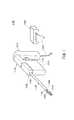
図1には医療用のマニピュレータシステム1100が示される。マニピュレータシステム1100はマニピュレータ1102とコントロール装置1104を含む。マニピュレータ1102は作業部(作業機構)1106と、中空のシャフト1108と作業部コントロール機構1110を含む。シャフト1108は第1端部1107とその反対側の第2端部1109を持つ。一般的に、シャフト1108はワイヤ(動力伝達部材)が中を通る細長い管である。ワイヤは作業部1106と作業部コントロール機構1110をつなぐ。作業部1106はシャフト1108の第1端部に現在そして将来に亘って当業者に知られる様々な機構でマウントされる。作業部コントロール機構1110はシャフト1108の第2端部1109に現在そして将来に亘って当業者に知られる様々な機構でマウントされる。ここの記載においてマウント(mount)という表現は、一緒にする(join)、係合する(engage)、一体化する(unite)、接続する(connect)、関係付ける(associate)、挿入する(insert)、吊るす(hang)、保持する(hold)、固定する(affix)、添付する(attach)、締める(fasten)、束ねる(bind)、貼る(paste)、留める(secure)、締める(bolt)、ねじる(screw)、留める(rivet)、はんだ付けする(solder)、溶接する(weld)、そして他の類似の用語を含む。 FIG. 1 shows a
作業部コントロール機構1110は、現在から将来に亘って当業者に知られる機械的、電気機械的、電気的なものである。作業部コントロール機構1110はハンドル1112とコントロール本体1114を含む。外科医は現在そして将来において知られる低侵襲外科手術を作業部1106に接合される先端動作部1118を使って行うためハンドル1112を操作する。ハンドル1112は回転、抑え付け、トグル等、先端動作部1118に所望の動作を行わせるための機構を含む。例えば、ハンドル1112は先端動作部1118を開けたり閉じたりするボタン1116を含む。 The working
コントロール装置1104はケーブル導線1120を通して電気信号を作業部コントロール機構1110へ送ったり、作業部コントロール機構から受けたりする。例えば、コントロールソフトウエアがボタン1116の動作が示す電気信号を受け、これを先端動作部1118を動かすための適切な信号へ変換する。電気信号はアナログでもデジタルでもよい。 The
図2において、作業部1106は先端動作部1118、本体1200、マウント機構1202そして回転程度認識手段1208を含む。回転程度認識手段1208は、ロール回転機構で相対的に回転をする基端側部材と先端側部材の少なくとも一方の部材に設けられるものであって、他方の部材の回転の程度を示す。 In FIG. 2, the working
本体1200は第1端部1204、その反対側の第2端部1206を含む。先端動作部1118は本体1200の第1端部1204に位置する。マウント機構1202は本体1200の第2端部1206に位置する。作業部1106と先端動作部1118は現在そして将来に亘って当業者に知られる切開、剥離、縫合、把持等のためにデザインされた様々の異なった仕様を持つ。作業部1106とシャフト1108の第1端部1107とのマウント機構1202は現在そして将来に亘って当業者に知られる様々の仕様が用いられる。 The
マニピュレータ1102の使用中にシャフト1108は動力によっては回転せず、作業部1106が回転する。作業部1106は本体1200の第1端部1204と第2端部1206に延びる軸B−Bの周りをR−Rの方向に回転する。一般的に軸B−Bはシャフト1108の第1端部1107と第2端部1109方向へ延びる。回転程度認識手段1208は先端動作部1118及び/又は作業部1106のR−R方向の回転の程度を示す。回転の程度とは、基準の姿勢に対する回転角度である。 While the
回転程度認識手段1208は本体1200の第2端部1206の近くに付けられる。例えば、回転程度認識手段1208は本体1200に印刷、埋め込み又は接着される。具体例として、回転程度認識手段1208はくさび形状を持ち、外科医が手術中に目視確認できるようになっている。回転程度認識手段1208は本体1200の弧の部分に延びる複数のくさび形状を持つ。くさび形状はそれぞれ同じでも異なっていてもよい。弧部分の曲がり程度は作業部1106の大きさによって異なる。くさび形状は作業部1106のR−R軸回転に従って、広がったり、狭くなったりする。くさび形状の広がりや狭まりが作業部1106の回転の程度を外科医に示す。 The rotation degree recognition means 1208 is attached near the
シャフト1108はアライメントインジケータ1210を第1端部1107の近くにマウントする。アライメントインジケータ1210はシャフト1108に対する作業部1106の初期アライメント位置を示す。さらに外科医が作業部1106の回転の程度を認識することを助け、縫合、切開又は他の外科的手技を行う際の助けとなる。
回転程度認識手段1208及びアライメントインジケータ1210は、最先端のグリッパ202及び212よりはある程度基端側であり、グリッパ202及び212が内視鏡で見えない場合であっても、視認できる可能性が非常に高い。 The rotation
図2に示す作業部1106の構成について、図3及び図4に基づいてさらに詳細に説明する。 The configuration of the working
図3に示すように、先端動作部1118はY方向の第1回転軸(ピボット軸)Oyを中心にして、それよりも先の部分がヨー方向に回動する第1自由度と、第2回転軸Or(先端を指向する軸)を中心にしてロール方向に回動する第2自由度(ロール回転機構)と、第3回転軸Ogを中心として先端のエンドエフェクタ104を開閉させる第3自由度とを有する合計3自由度の機構となっている。第2回転軸Orはヨー方向の動作の有無に関わらずに先端を指向している軸である。 As shown in FIG. 3, the distal
エンドエフェクタ104は、手術において実際の作業を行う部分であり、第1回転軸Oy及び第2回転軸Orは、作業を行いやすいようにエンドエフェクタ104の姿勢を変えるためのものである。一般に、エンドエフェクタ104を開閉させる第3自由度に係る機構部をグリッパ軸とも呼ばれ、ヨー方向に回動する第1自由度に係る機構部をヨー軸とも呼ばれ、ロール方向に回動する第2自由度に係る機構部をロール軸とも呼ばれる。 The
先端動作部1118は、ワイヤ受動部100と、複合機構部102と、エンドエフェクタ104とを有する。 The distal
図3、図4を参照しながら、ワイヤ受動部100、複合機構部102及びエンドエフェクタ104について詳細に説明する。 The wire
ワイヤ受動部100は、一対の舌片部58の間に設けられており、ワイヤ52、ワイヤ54及びワイヤ56のそれぞれの往復動作を回転動作に変換して複合機構部102に伝達する部分である。ワイヤ受動部100は、軸孔60a、60aに挿入される軸110と、軸孔60b、60bに挿入される軸(直交軸)112と、軸110に対して回転自在に軸支される歯車体114とを有する。軸110及び112は、軸孔60a、60bに対して、例えば圧入若しくは溶接により固定される。軸112は第1回転軸Oyの軸上に配置される。 The wire
歯車体114は、筒体116と、該筒体116の上部に同心状に設けられた歯車118とを有する。歯車118は筒体116よりも大径の平歯車である。以下、特に断らない限り歯車は平歯車である。歯車体114は一対の舌片部58の間に回転自在に配置される。歯車118の上面には、軸110が挿入される孔の周辺に低い環状リブ118aが設けられており、歯車118の上面が上側の舌片部58に接触することが防止され摺動抵抗の低減を図っている。 The
複合機構部102は、エンドエフェクタ104の開閉動作機構と、該エンドエフェクタ104の姿勢を変化させる複合的な機構部である。 The
複合機構部102は、Y1方向からY2方向に向かって順に、軸112に対して回転自在に軸支される歯車体126と、主軸部材128と、歯車体130とを有する。 The
歯車体126は、筒体132と、該筒体132の上部に同心状に設けられた歯車134とを有する。歯車134は歯車118と同じ厚さで、該歯車118と噛合するように設定されている。歯車134は歯車118よりも歯数が多く、歯車118の回転が減速して(トルクが増大して)伝達することができる。もちろん、設計条件に応じて同速又は増速するように伝達してもよい。歯車134の上面には、軸112が挿入される孔の周辺に低い環状リブ134aが設けられており、歯車134の上面が上側の舌片部58に接触することが防止され摺動抵抗の低減を図っている。 The
歯車体130は、歯車体126とほぼ同形状であって、該歯車体126に対して上下反転に配置されている。歯車体130は、筒体136と、該筒体136の下部に同心状に設けられた歯車138とを有する。筒体136は筒体132と略同径、同形状である。歯車138は、歯車134よりも歯数をやや少なくするこができる。筒体136のZ2方向の側の面には、筒体116と同様のワイヤ固定機構120が設けられており、ワイヤ54を固定している。 The
主軸部材128は、軸112が挿通する筒体140と、Z1方向に設けられた環状座面142と、該環状座面142の中心からZ1方向に延在する支持バー144とを有する。支持バー144は第2回転軸Orの軸上に配置される。支持バー144の先端部には雄ねじが設けられている。 The
環状座面142は保護板171を介して、筒体140の外側面よりもやや離れた位置に設けられており、環状座面142と筒体140との間にはワイヤ52が挿通可能な孔146が設けられている。筒体140のZ2方向の側の面には、筒体116と同様のワイヤ固定機構120が設けられており、ワイヤ52を固定している。 The
保護板171はZ2方向が略90°の円弧形状であり、Z1方向に向かって拡開しており、平面視で略山形となっている。 The
主軸部材128は、ワイヤ52の往復動作に伴って第1回転軸Oyを中心としたヨー方向に回転し、支持バー144をXZ平面上で揺動させることができる。 The
筒体140、歯車体126及び歯車体130は、軸112を軸として積層配置されており、一対の舌片部58の間にほぼ隙間なく設けられている。 The
複合機構部102は、さらに駆動ベース150と、歯車リング152と、歯車付きピン154と、固定ナット156及び158と、カバー160とを有する。固定ナット156には、細い回転工具を挿入するための径方向の複数の細孔156aが設けられている。細孔156aの少なくとも1つは、径方向に露呈している(図4参照)。固定ナット158には、スパナ等の回転工具を係合可能な平行面158aが設けられている。 The
駆動ベース150は、支持バー144の基端部に回動自在に挿入される筒体164と、該筒体164の左右両端からZ1方向に向かって突出している一対の支持アーム166と、筒体164のZ2方向の面に設けられたフェイスギア168とを有する。各支持アーム166はエンドエフェクタ104を支持する部分であり、X方向に並んだ孔166aが設けられている。筒体164を支持バー144の基端部に挿入した後に、固定ナット156を支持バー144の先端の雄ねじに螺着させることにより、駆動ベース150は支持バー144を中心とした(つまり、第2回転軸Orを中心とした)ロール方向に、回動自在に軸支される。 The
フェイスギア168は歯車138に噛合し、駆動ベース150は筒体136の回転にともなって、第2回転軸Orを中心として回転可能である。 The
歯車リング152は薄い筒体であって、Z2方向の面に設けられたフェイスギア170と、Z1方向の面に設けられたフェイスギア172とを有する。歯車リング152は駆動ベース150の筒体164に嵌装され、該筒体164の周面に対して摺動回転自在となる。歯車リング152は、フェイスギア170が駆動ベース150のフェイスギア168よりもややZ1方向側の位置であって、歯車134に噛合する位置まで筒体164に嵌装される。フェイスギア170は歯車134に噛合し、歯車リング152は歯車体126の回転に伴って第2回転軸Orを中心として回転可能である。 The
歯車付きピン154は、フェイスギア172に噛合する歯車174と、該歯車174の中心からX1方向に延在するピン176とを有する。ピン176の先端部には雄ねじが設けられている。ピン176は2つの孔166aを通って雄ねじが反対側の支持アーム166から突出し、固定ナット158が螺着される。これにより、歯車付きピン154は、歯車174がフェイスギア172に噛合するとともに、支持アーム166に対して回動自在に軸支される。また、ピン176はエンドエフェクタ104の一部に係合するようにDカット形状となっている。 The geared
カバー160は、複合機構部102及びエンドエフェクタ104の各部品を保護するためのものであって、歯車リング152、歯車174等を覆う。カバー160は、Z2方向の筒180と、該筒180の左右側方からZ1方向に向かって突出している一対の片182とを有する。片182は、筒180の周壁の一部が緩やかな円錐状にZ1方向に延在している形状である。カバー160の下部はカバー固定ピン162によってエンドエフェクタ104の一部に固定されている。カバー160は正面視でシャフト1108と同径又は小径に設定されている。 The
図3から明らかなように、複合機構部102及びエンドエフェクタ104は軸方向に長尺形状となっている。 As is apparent from FIG. 3, the
カバー160は、複合機構部102、エンドエフェクタ104を動作に支障のない範囲でほぼ全域にわたり覆うように円筒や円錐形のカバーで構成してもよい。また、ピン196を利用してカバー160を固定してもよい。 The
このようなカバー160によれば、作業部としての複合機構部102及びエンドエフェクタ104に異物(生体組織、薬剤、糸等)が入り込むことが防止される。 According to such a
次に、エンドエフェクタ104は、第1エンドエフェクタ部材190と、第2エンドエフェクタ部材192と、リンク194と、ピン196とを有する。ピン196は第3回転軸Ogの軸上に配置される。 Next, the
第1エンドエフェクタ部材190は、左右に対向して設けられた一対のサイドウォール200と、サイドウォール200の先端部にそれぞれ設けられた孔200aと、サイドウォール200の後端部にそれぞれ設けられた孔200bと、サイドウォール200の先端下部からZ1に突出した第1グリッパ202と、サイドウォール200の後端下部に設けられたカバー固定部204とを有する。孔200aはピン196が、例えば圧入されるのに適した径に設定されている。第1グリッパ202はZ1方向に向かってやや幅狭となって、先端部が円弧状となる形状であり、Y1方向の全面には小さい錐上突起がほぼ隙間なく設けられている。 The first
各サイドウォール200の先端部は円弧状に形成されており、後端部の両外側面には前記の支持アーム166が嵌り込む凹部200cが設けられている。第1グリッパ202とカバー固定部204との間には、第2エンドエフェクタ部材192の後端部に対する干渉を防止する孔190a(図4参照)が設けられている。カバー固定部204には、カバー固定ピン162が、例えば圧入される孔が設けられている。 The front end portion of each
第2エンドエフェクタ部材192は、ベース部210と、ベース部210の先端からZ1方向に延在する第2グリッパ212と、ベース部210の左右後端からZ2方向に延在する一対の耳片部214と、ベース部210の先端下部に設けられた軸支筒216とを有する。軸支筒216はピン196が挿入可能な程度の内径の孔216aを有している。ピン196が軸支筒216に挿入されて孔200aに対して、例えば圧入されることにより、第2エンドエフェクタ部材192は第3回転軸Ogを中心として揺動自在となる。第2グリッパ212は第1グリッパ202と同形状で上下反転に配置されており、第2エンドエフェクタ部材192が第3回転軸Ogを中心として回動したときに第1グリッパ202に対して当接し、湾曲針等を把持することができる。耳片部214にはそれぞれ長孔214aが設けられている。 The second
リンク194は、一方の端部に設けられた孔220と、他方の端部に設けられて左右に突出する一対の係合部222とを有する。各係合部222は長孔214aに対して摺動可能に係合している。孔220はピン176が係合するに適したDカット形状に形成されており、該ピン176に対する位置決め機能及び回り止め機能を有する。ピン176が孔166a、孔200b及び220に挿入されるとともに、先端部に固定ナット158が螺着されることにより、リンク194はピン176を中心として揺動自在となる。 The
回転程度認識手段1208は、例えば、カバー(ロール回転機構の先端側部材)160のZ2方向端部に設けると視認しやすい。カバー160は周方向に連続しており、しかも適度な面積があり、回転程度認識手段1208を設けるのに好適である。アライメントインジケータ1210は、例えば、上方のシャフト1108の(ロール回転機構の基端側部材)先端側面1108aに設けると、回転程度認識手段1208に近くてよい。先端側面1108aは、ヨー方向の回転が発生しても回転程度認識手段1208に対するロール方向の相対位置が変わらず、アライメントインジケータ1210を設けるのに好適である。つまり、アライメントインジケータ1210は、ヨー方向回転の第2回転軸Orに沿った側方平行面に設けられるとよい。 For example, the rotation
図3における符号1210aで示すように、アライメントインジケータは、保護板171の側面に設けてもよい。この位置は、カバー160とほとんど接する位置であり、しかもヨー軸動作による影響がない位置であり、アライメントインジケータ1210aが回転程度認識手段1208を指し示すのに好適である。 As indicated by reference numeral 1210 a in FIG. 3, the alignment indicator may be provided on the side surface of the
回転程度認識手段1208は、ロール回転機構で相対的に回転をする基端側部材と先端側部材の少なくとも一方の部材に設ければよい。他方の部材には、アライメントインジケータ1210を設けるとよい。 The rotation
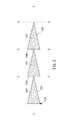
図5に回転程度認識手段1208の第1の実施例を符号1300として示す。軸A−Aは回転軸R−Rの方向に延びる。ただし、回転程度認識手段1300の全体を表示するためにここには展開された状態を示す。回転程度認識手段1300は第1の二等辺三角形1302、第2の二等辺三角形1304、第3の二等辺三角形1306そして第2アライメントインジケータ1308を含む。第1の二等辺三角形1302、第2の二等辺三角形1304、第3の二等辺三角形1306の中心は回転方向R−Rに延びる軸A−Aに沿って揃えられる。軸C−Cと軸D−Dは軸B−Bと平行である。軸B−B、C−C、D−Dは回転程度認識手段1300の円周方向の位置を示す。第1の二等辺三角形1302は軸B−Bと軸C−Cの間に延びる。第2の二等辺三角形1304は軸C−Cと軸D−Dの間に延びる。第3の二等辺三角形1306は軸D−Dと軸B−Bの間に延びる。図5に示されるように、第1の二等辺三角形1302、第2の二等辺三角形1304、第3の二等辺三角形1306はそれぞれ円周方向に120°ずつを占める。 FIG. 5 shows a first embodiment of the rotation degree recognition means 1208 as a
第1の二等辺三角形1302は第1の認識手段1303を含む。第2の二等辺三角形1304は第2の認識手段1305を含む。第3の二等辺三角形1306は第3の認識手段1307を含む。図5に示す例において、第1の認識手段1303は「1」、第2の認識手段1305は「2」、第3の認識手段1307は「3」である。認識手段1303、1305、1307はそれぞれの二等辺三角形1302、1304、1306を区別する。そして、外科医が作業部1106の回転の程度を認識するのを助ける。 The first
第2のアライメントインジケータ1308は回転程度認識手段1300について回転表示の最初の位置を示す。そして、外科医が作業部1106の回転の程度を認識するのを助ける。 The
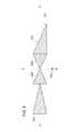
図6は回転程度認識手段1208の第2の実施例を符号1400として示す。軸A−Aは回転軸R−Rの方向に延びるが、回転程度認識手段1400の全体像を示すために展開した状態を示す。回転程度認識手段1400は第1の二等辺三角形1402、第2の二等辺三角形1404、第3の二等辺三角形1406、直角三角形1408そして第2のアライメントインジケータ1308を含む。第1の二等辺三角形1402、第2の二等辺三角形1404、第3の二等辺三角形1406そして直角三角形1408は回転R−R方向に沿う軸A−Aに沿って三角形の中央部で揃えられ並べられる。図6に示される実施例において、第1の二等辺三角形1402と直角三角形1408はそれぞれ120°ずつ回転方向の位置を占める。第2の二等辺三角形1404と第3の二等辺三角形1406は60°ずつ回転方向の位置を占める。第2の二等辺三角形1404と第3の二等辺三角形1406はそれぞれ鏡像関係にある。第3の二等辺三角形1406は直角三角形1408の底辺と接する。直角三角形1408の頂点は第1の二等辺三角形1402の底辺と接する。第2のアライメントインジケータ1308は第2の二等辺三角形1404と第3の二等辺三角形1406の間に延びる軸B−Bと一致される。 FIG. 6 shows a second embodiment of the degree of rotation recognition means 1208 as 1400. The axis A-A extends in the direction of the rotation axis RR, but shows a developed state to show the entire image of the rotation degree recognition means 1400. The rotation
図7には第3の実施例である回転程度認識手段1500が示される。軸A−Aは回転R−Rの方向に延びるが、回転程度認識手段1500の全体がわかるように、展開した状態で示される。回転程度認識手段1500は第1直角三角形1502、第2直角三角形1504、第3直角三角形1506、第4直角三角形1508そして第2アライメントインジケータ1308を含む。第1直角三角形1502、第2直角三角形1504、第3直角三角形1506そして第4直角三角形1508は回転R−Rの方向の軸A−Aに沿ってそれぞれの三角形の長辺1502a、1504a、1506a及び1508aを揃えて整列される。ここで長辺とは、それぞれ直角を構成する2辺のうち長い方の辺であり、斜辺に次ぐ長さの辺を意味する。軸A−Aに沿わせるのは、最短辺以外の辺であると、方向性を示しやすく、しかもB−B方向に無駄に幅広にならず好適である。図7の実施例では、それぞれの三角形は回転方向に90°ずつ均等に占める。第2直角三角形1504と第3直角三角形1506はその頂点を接し、鏡像の関係にある。第1直角三角形1502の頂点と第2直角三角形の底辺は接している。第4直角三角形1508の頂点と第3直角三角形1506の底辺は接している。 FIG. 7 shows a rotation degree recognition means 1500 according to the third embodiment. The axis AA extends in the direction of the rotation RR, but is shown in an unfolded state so that the entire rotation degree recognition means 1500 can be seen. The rotation
第2アライメントインジケータ1308は第2直角三角形1504と第3直角三角形1506との間に延びる軸B−B上に合わせられる。 The
第1直角三角形1502は第1認識指標1503を含む。第2直角三角形1504は第2認識指標1505を含む。第3直角三角形1506は第3認識指標1507を含む。第4直角三角形1508は第4認識指標1509を含む。図7に示されるように、第1認識指標1503は文字「A」であり、第2認識指標1505は文字「B」であり、第3認識指標1507は文字「C」であり、第4認識指標1509は文字「D」である。認識指標1503、1505、1507、1509は直角三角形1502、1504、1506、1508をそれぞれ区別するものであり、さらに外科医が作業部1106の回転の程度を確認することを助ける。 The first
ところで、カバー160のような円筒を側面から見れば、理論的には最大180°の範囲が見えるが、体腔22内等で内視鏡で観察する場合には十分な明るさがあるとは言えず、円筒の端の方は陰になってしまい、十分に視認できるのは正面の120°程度である。 By the way, when a cylinder such as the
そこで、カバー160に設けられる回転程度認識手段の形状は120°の範囲で変化をもたせることが望ましい。 Therefore, it is desirable that the shape of the rotation degree recognizing means provided in the
例えば、回転程度認識手段を構成する複数の形状部のうち一つの形状部を最大120°にするとそれ一つしか見えない場合で、その形状部だけでは角度が判断できないときには、第2の回転程度認識手段である認識指標を設けるとよい。これらの認識指標は例えば文字、数字等を用いることができる。図7に示す認識指標1503、1505、1507、1509はこの第2の回転程度認識手段に相当する。 For example, when only one of the plurality of shape parts constituting the rotation degree recognition means is visible when the maximum shape is 120 ° and the angle cannot be determined by only the shape part, the second rotation degree It is preferable to provide a recognition index that is a recognition means. For example, letters, numbers, and the like can be used as these recognition indexes.
また、内視鏡による映像ではロール軸の回転が0°を基準とした+側なのか−側なのかの判断が困難である場合がある。このような、ロール軸角度の極性を判断するために、図6に示す回転程度認識手段1400及び図7に示す回転程度認識手段1500では、回転程度認識手段を構成する個々の形状部(三角形)はA−A軸で非対称となっている。また、図7に示す回転程度認識手段1500では、全体として、0°位置(図7のB−B軸)を基準として対称になっている。 In addition, in an endoscope image, it may be difficult to determine whether the rotation of the roll shaft is the + side or the − side with respect to 0 °. In order to determine the polarity of the roll axis angle, in the rotation
これにより、内視鏡の映像を見ながらであってもロール軸を+側又は−側のいずれか所望の方向に回転させることが容易である。また、その時点のロール軸姿勢の極性が+側又は−側のいずれであるか容易に判断できる。さらに、ロール軸を0°姿勢に戻す操作が容易である。 Thereby, it is easy to rotate the roll axis in a desired direction on either the + side or the − side even while viewing the image of the endoscope. Further, it can be easily determined whether the polarity of the roll axis posture at that time is the + side or the-side. Furthermore, the operation of returning the roll axis to the 0 ° posture is easy.
図6に示す回転程度認識手段1400では、B−B軸についても非対称としており、識別性を向上させている。 In the rotation
回転程度認識手段1208は作業部1106の回転の程度を視認できるものであれば様々の形状が採用される。いくつかの三角形を具体例として示してきたが、これらは三角形の辺によって形成される曲線が視認しやすいものである。他の例としては弧状のもの、階段状のもの等がある。さらに、台形、長方形、六角形、円等も採用できる。さらに、周方向の間隔も他の実施例、例えば9個の形状物で40°ずつということもできる。少なくとも2個以上の形状物で形成されるのがよい。 The rotation
また、回転程度認識手段は、本体表面上に示されるものに限らず、図8に示す切欠1600や突起1602であってもよい。これらの切欠1600や突起1602は、周面に設けられるものであってもよいし、軸方向端面に設けられるものであってもよい。回転程度認識手段は、三角形等の形状で表すものに限らず、図9に示す色彩や模様1610を用いてもよい。色彩を用いる場合、例えばグラデーション状の表示として回転角度を示してもよい。色彩は図面上で表現できないことから図示を省略する。 Further, the rotation degree recognition means is not limited to that shown on the surface of the main body, and may be the
上述した医療用マニピュレータによれば、回転程度認識手段を有することにより、最先端のグリッパが内視鏡でも明りょうに認識できない場合であっても操作者は該ロール回転機構の回転角度を容易に認識することができる。 According to the medical manipulator described above, by having the rotation degree recognition means, the operator can easily determine the rotation angle of the roll rotation mechanism even when the state-of-the-art gripper cannot be clearly recognized even by the endoscope. Can be recognized.
また、グリッパ202及び212は略対称構造であり、ロール回転機構が180°回転してしまうと、グリッパ202及び212を見ても、回転角度が分かりにくいが、回転程度認識手段を見ることによりロール回転機構の回転角度を容易に認識することができる。さらに、ロール回転機構が360°以上回転した場合であっても、相当に有効である。例えば、回転程度認識手段が45°を示している場合、操作者がロール回転機構を360°以上回転させたことを認識していれば、現在の角度は405°(=360+45)であることを容易に認識することができる。 Further, the
上記実施例は、例えば図10に示すような手術用ロボットシステム700に適用してもよい。 The above embodiment may be applied to a
手術用ロボットシステム700は、多関節型のロボットアーム702と、コンソール704とを有し、作業部1106はロボットアーム702の先端に接続されている。ロボットアーム702の先端には前記のコントロール本体1114と同じ機構を設けることにより、作業部1106を接続及び駆動可能である。ロボットアーム702は、作業部1106を移動させる手段であればよく、据置型に限らず、例えば自律移動型でもよい。コンソール704は、テーブル型、制御盤型等の構成を採り得る。 The
ロボットアーム702は、独立的な6以上の関節(回転軸やスライド軸等)を有すると、作業部1106の位置及び向きを任意に設定できて好適である。先端のコントロール本体1114は、ロボットアーム702の先端部708と一体化している。 If the
ロボットアーム702は、コンソール704の作用下に動作し、プログラムによる自動動作や、コンソール704に設けられたジョイスティック706に倣った操作、及びこれらの複合的な動作をする構成にしてもよい。コンソール704は、前記のコントロール装置1104の機能を含んでいる。 The
作業部1106の先端動作部1118には、前記の通り回転程度認識手段1208及びアライメントインジケータ1210が設けられている。 As described above, the rotation
コンソール704には、操作指令部としての2つのジョイスティック706と、モニタ710が設けられている。図示を省略するが、2つのジョイスティック706により、2台のロボットアーム702を個別に操作が可能である。2つのジョイスティック706は、両手で操作しやすい位置に設けられている。モニタ710には、内視鏡による画像等の情報が表示される。 The
ジョイスティック706は、上下動作、左右動作、捻り動作、及び傾動動作が可能であり、これらの動作に応じてロボットアーム702を動かすことができる。ジョイスティック706はマスターアームであってもよい。ロボットアーム702とコンソール704との間の通信手段は、有線、無線、ネットワーク又はこれらの組合わせでよい。 The
本発明に係る医療用マニピュレータは、上述の実施の形態に限らず、本発明の要旨を逸脱することなく、種々の構成を採り得ることはもちろんである。 The medical manipulator according to the present invention is not limited to the above-described embodiment, and various configurations can be adopted without departing from the gist of the present invention.
1100…マニピュレータシステム 1102…マニピュレータ
1104…コントロール装置 1106…作業部
1107、1204…第1端部 1108…シャフト
1109、1206…第2端部 1118…先端動作部
1200…本体
1208、1300、1400、1500…回転程度認識手段
1210、1210a、1308…アライメントインジケータ
1302、1304、1306、1402、1404、1406…二等辺三角形
1303、1305、1307…認識手段
1408、1502、1504、1506、1508…直角三角形
1503、1505、1507、1509…認識指標
1600…切欠(回転程度認識手段) 1610…模様(回転程度認識手段)DESCRIPTION OF
Claims (4)
Translated fromJapanese前記シャフトに設けられたワイヤと、
前記シャフトの先端に設けられ、前記ワイヤによって動作し、先端を指向する軸を中心に回転するロール回転機構を含む先端動作部を備える作業部と、
を有し、
前記先端動作部は、針を把持するためのエンドエフェクタを有し、
前記ワイヤは、前記ロール回転機構の一部を構成する筒体に固定され、
前記筒体が前記ワイヤにより回転されることにより、前記ロール回転機構が駆動され、
前記ロール回転機構で前記シャフトに対して相対的にロール回転をする前記先端動作部に、当該先端動作部の前記シャフトに対するロール回転の程度を示す回転程度認識手段を有することを特徴とする医療用マニピュレータ。A hollow shaft,
Awire provided on the shaft;
Said providedfirst end of the shaft, operated by thewire, the working portion including a distal end working unit including a rolling mechanism rotatable about an axis directed to a distal end,
Have
The distal end working unit has an end effector for gripping a needle,
The wire is fixed to a cylinder constituting a part of the roll rotation mechanism,
When the cylinder is rotated by the wire, the roll rotation mechanism is driven,
The medical device characterized inthat the distal end working unit thatperformsroll rotation relative to theshaft by the roll rotating mechanism has a rotation degree recognizing means that indicates a degreeof roll rotation of thedistal end working unit withrespect to the shaft . manipulator.
前記シャフトの先端部に、前記先端動作部の初期の位置を示すアライメントインジケータを有することを特徴とする医療用マニピュレータ。The medical manipulator according to claim 1, wherein
A medical manipulator having an alignment indicator indicating an initial position of thedistal end working portion ata distal end portion of theshaft .
前記回転程度認識手段は切欠又は突起であることを特徴とする医療用マニピュレータ。The medical manipulator according to claim 1 or 2,
The medical manipulator characterized in that the rotation degree recognition means is a notch or a protrusion.
前記回転程度認識手段は色彩又は模様であることを特徴とする医療用マニピュレータ。The medical manipulator according to claim 1 or 2,
The medical manipulator characterized in that the rotation degree recognition means is a color or a pattern.
Priority Applications (3)
| Application Number | Priority Date | Filing Date | Title |
|---|---|---|---|
| JP2007216638AJP5198014B2 (en) | 2006-10-25 | 2007-08-23 | Medical manipulator |
| EP07119217.3AEP1915957B1 (en) | 2006-10-25 | 2007-10-24 | Manipulator for medical use |
| US11/923,159US10245058B2 (en) | 2006-10-25 | 2007-10-24 | Manipulator for medical use |
Applications Claiming Priority (3)
| Application Number | Priority Date | Filing Date | Title |
|---|---|---|---|
| US86282106P | 2006-10-25 | 2006-10-25 | |
| US60/862821 | 2006-10-25 | ||
| JP2007216638AJP5198014B2 (en) | 2006-10-25 | 2007-08-23 | Medical manipulator |
Publications (2)
| Publication Number | Publication Date |
|---|---|
| JP2008104856A JP2008104856A (en) | 2008-05-08 |
| JP5198014B2true JP5198014B2 (en) | 2013-05-15 |
Family
ID=39671758
Family Applications (1)
| Application Number | Title | Priority Date | Filing Date |
|---|---|---|---|
| JP2007216638AActiveJP5198014B2 (en) | 2006-10-25 | 2007-08-23 | Medical manipulator |
Country Status (3)
| Country | Link |
|---|---|
| US (1) | US10245058B2 (en) |
| EP (1) | EP1915957B1 (en) |
| JP (1) | JP5198014B2 (en) |
Cited By (2)
| Publication number | Priority date | Publication date | Assignee | Title |
|---|---|---|---|---|
| US11083533B2 (en) | 2016-02-25 | 2021-08-10 | Olympus Corporation | Manipulator system and operating method thereof |
| US11298199B2 (en) | 2016-02-25 | 2022-04-12 | Olympus Corporation | Manipulator system and method for restricting a retreating motion of a manipulator according to a protrusion state of a manipulator joint |
Families Citing this family (555)
| Publication number | Priority date | Publication date | Assignee | Title |
|---|---|---|---|---|
| US9060770B2 (en) | 2003-05-20 | 2015-06-23 | Ethicon Endo-Surgery, Inc. | Robotically-driven surgical instrument with E-beam driver |
| US20070084897A1 (en) | 2003-05-20 | 2007-04-19 | Shelton Frederick E Iv | Articulating surgical stapling instrument incorporating a two-piece e-beam firing mechanism |
| US11998198B2 (en) | 2004-07-28 | 2024-06-04 | Cilag Gmbh International | Surgical stapling instrument incorporating a two-piece E-beam firing mechanism |
| US9072535B2 (en) | 2011-05-27 | 2015-07-07 | Ethicon Endo-Surgery, Inc. | Surgical stapling instruments with rotatable staple deployment arrangements |
| US8215531B2 (en) | 2004-07-28 | 2012-07-10 | Ethicon Endo-Surgery, Inc. | Surgical stapling instrument having a medical substance dispenser |
| US11890012B2 (en) | 2004-07-28 | 2024-02-06 | Cilag Gmbh International | Staple cartridge comprising cartridge body and attached support |
| US7669746B2 (en) | 2005-08-31 | 2010-03-02 | Ethicon Endo-Surgery, Inc. | Staple cartridges for forming staples having differing formed staple heights |
| US8800838B2 (en) | 2005-08-31 | 2014-08-12 | Ethicon Endo-Surgery, Inc. | Robotically-controlled cable-based surgical end effectors |
| US9237891B2 (en) | 2005-08-31 | 2016-01-19 | Ethicon Endo-Surgery, Inc. | Robotically-controlled surgical stapling devices that produce formed staples having different lengths |
| US11246590B2 (en) | 2005-08-31 | 2022-02-15 | Cilag Gmbh International | Staple cartridge including staple drivers having different unfired heights |
| US10159482B2 (en) | 2005-08-31 | 2018-12-25 | Ethicon Llc | Fastener cartridge assembly comprising a fixed anvil and different staple heights |
| US7934630B2 (en) | 2005-08-31 | 2011-05-03 | Ethicon Endo-Surgery, Inc. | Staple cartridges for forming staples having differing formed staple heights |
| US7673781B2 (en) | 2005-08-31 | 2010-03-09 | Ethicon Endo-Surgery, Inc. | Surgical stapling device with staple driver that supports multiple wire diameter staples |
| US11484312B2 (en) | 2005-08-31 | 2022-11-01 | Cilag Gmbh International | Staple cartridge comprising a staple driver arrangement |
| US20070106317A1 (en) | 2005-11-09 | 2007-05-10 | Shelton Frederick E Iv | Hydraulically and electrically actuated articulation joints for surgical instruments |
| US7845537B2 (en) | 2006-01-31 | 2010-12-07 | Ethicon Endo-Surgery, Inc. | Surgical instrument having recording capabilities |
| US7753904B2 (en) | 2006-01-31 | 2010-07-13 | Ethicon Endo-Surgery, Inc. | Endoscopic surgical instrument with a handle that can articulate with respect to the shaft |
| US11224427B2 (en) | 2006-01-31 | 2022-01-18 | Cilag Gmbh International | Surgical stapling system including a console and retraction assembly |
| US20110024477A1 (en) | 2009-02-06 | 2011-02-03 | Hall Steven G | Driven Surgical Stapler Improvements |
| US20110295295A1 (en) | 2006-01-31 | 2011-12-01 | Ethicon Endo-Surgery, Inc. | Robotically-controlled surgical instrument having recording capabilities |
| US8186555B2 (en) | 2006-01-31 | 2012-05-29 | Ethicon Endo-Surgery, Inc. | Motor-driven surgical cutting and fastening instrument with mechanical closure system |
| US11793518B2 (en) | 2006-01-31 | 2023-10-24 | Cilag Gmbh International | Powered surgical instruments with firing system lockout arrangements |
| US20120292367A1 (en) | 2006-01-31 | 2012-11-22 | Ethicon Endo-Surgery, Inc. | Robotically-controlled end effector |
| US9861359B2 (en) | 2006-01-31 | 2018-01-09 | Ethicon Llc | Powered surgical instruments with firing system lockout arrangements |
| US8820603B2 (en) | 2006-01-31 | 2014-09-02 | Ethicon Endo-Surgery, Inc. | Accessing data stored in a memory of a surgical instrument |
| US8161977B2 (en) | 2006-01-31 | 2012-04-24 | Ethicon Endo-Surgery, Inc. | Accessing data stored in a memory of a surgical instrument |
| US8763879B2 (en) | 2006-01-31 | 2014-07-01 | Ethicon Endo-Surgery, Inc. | Accessing data stored in a memory of surgical instrument |
| US8708213B2 (en) | 2006-01-31 | 2014-04-29 | Ethicon Endo-Surgery, Inc. | Surgical instrument having a feedback system |
| US11278279B2 (en) | 2006-01-31 | 2022-03-22 | Cilag Gmbh International | Surgical instrument assembly |
| US8236010B2 (en) | 2006-03-23 | 2012-08-07 | Ethicon Endo-Surgery, Inc. | Surgical fastener and cutter with mimicking end effector |
| US8992422B2 (en) | 2006-03-23 | 2015-03-31 | Ethicon Endo-Surgery, Inc. | Robotically-controlled endoscopic accessory channel |
| US8322455B2 (en) | 2006-06-27 | 2012-12-04 | Ethicon Endo-Surgery, Inc. | Manually driven surgical cutting and fastening instrument |
| US7506791B2 (en) | 2006-09-29 | 2009-03-24 | Ethicon Endo-Surgery, Inc. | Surgical stapling instrument with mechanical mechanism for limiting maximum tissue compression |
| US10130359B2 (en) | 2006-09-29 | 2018-11-20 | Ethicon Llc | Method for forming a staple |
| US10568652B2 (en) | 2006-09-29 | 2020-02-25 | Ethicon Llc | Surgical staples having attached drivers of different heights and stapling instruments for deploying the same |
| US11980366B2 (en) | 2006-10-03 | 2024-05-14 | Cilag Gmbh International | Surgical instrument |
| JP5481194B2 (en) | 2006-10-05 | 2014-04-23 | コヴィディエン リミテッド パートナーシップ | Flexible endoscopic suturing device |
| US8226667B2 (en) | 2006-10-05 | 2012-07-24 | Tyco Healthcare Group Lp | Axial stitching device |
| US8684253B2 (en) | 2007-01-10 | 2014-04-01 | Ethicon Endo-Surgery, Inc. | Surgical instrument with wireless communication between a control unit of a robotic system and remote sensor |
| US11291441B2 (en) | 2007-01-10 | 2022-04-05 | Cilag Gmbh International | Surgical instrument with wireless communication between control unit and remote sensor |
| US8652120B2 (en) | 2007-01-10 | 2014-02-18 | Ethicon Endo-Surgery, Inc. | Surgical instrument with wireless communication between control unit and sensor transponders |
| US8459520B2 (en) | 2007-01-10 | 2013-06-11 | Ethicon Endo-Surgery, Inc. | Surgical instrument with wireless communication between control unit and remote sensor |
| US8632535B2 (en) | 2007-01-10 | 2014-01-21 | Ethicon Endo-Surgery, Inc. | Interlock and surgical instrument including same |
| US20080169333A1 (en) | 2007-01-11 | 2008-07-17 | Shelton Frederick E | Surgical stapler end effector with tapered distal end |
| US11039836B2 (en) | 2007-01-11 | 2021-06-22 | Cilag Gmbh International | Staple cartridge for use with a surgical stapling instrument |
| US7673782B2 (en) | 2007-03-15 | 2010-03-09 | Ethicon Endo-Surgery, Inc. | Surgical stapling instrument having a releasable buttress material |
| US8893946B2 (en) | 2007-03-28 | 2014-11-25 | Ethicon Endo-Surgery, Inc. | Laparoscopic tissue thickness and clamp load measuring devices |
| US7810693B2 (en) | 2007-05-30 | 2010-10-12 | Ethicon Endo-Surgery, Inc. | Surgical stapling and cutting instrument with articulatable end effector |
| US7549564B2 (en)* | 2007-06-22 | 2009-06-23 | Ethicon Endo-Surgery, Inc. | Surgical stapling instrument with an articulating end effector |
| US7798386B2 (en)* | 2007-05-30 | 2010-09-21 | Ethicon Endo-Surgery, Inc. | Surgical instrument articulation joint cover |
| US8534528B2 (en) | 2007-06-04 | 2013-09-17 | Ethicon Endo-Surgery, Inc. | Surgical instrument having a multiple rate directional switching mechanism |
| US11564682B2 (en) | 2007-06-04 | 2023-01-31 | Cilag Gmbh International | Surgical stapler device |
| US7832408B2 (en) | 2007-06-04 | 2010-11-16 | Ethicon Endo-Surgery, Inc. | Surgical instrument having a directional switching mechanism |
| US8931682B2 (en) | 2007-06-04 | 2015-01-13 | Ethicon Endo-Surgery, Inc. | Robotically-controlled shaft based rotary drive systems for surgical instruments |
| US7597229B2 (en) | 2007-06-22 | 2009-10-06 | Ethicon Endo-Surgery, Inc. | End effector closure system for a surgical stapling instrument |
| US7658311B2 (en) | 2007-06-22 | 2010-02-09 | Ethicon Endo-Surgery, Inc. | Surgical stapling instrument with a geared return mechanism |
| US7604150B2 (en) | 2007-06-22 | 2009-10-20 | Ethicon Endo-Surgery, Inc. | Surgical stapling instrument with an anti-back up mechanism |
| US7753245B2 (en) | 2007-06-22 | 2010-07-13 | Ethicon Endo-Surgery, Inc. | Surgical stapling instruments |
| US8408439B2 (en) | 2007-06-22 | 2013-04-02 | Ethicon Endo-Surgery, Inc. | Surgical stapling instrument with an articulatable end effector |
| US11849941B2 (en) | 2007-06-29 | 2023-12-26 | Cilag Gmbh International | Staple cartridge having staple cavities extending at a transverse angle relative to a longitudinal cartridge axis |
| US8561870B2 (en) | 2008-02-13 | 2013-10-22 | Ethicon Endo-Surgery, Inc. | Surgical stapling instrument |
| US8657174B2 (en) | 2008-02-14 | 2014-02-25 | Ethicon Endo-Surgery, Inc. | Motorized surgical cutting and fastening instrument having handle based power source |
| US8758391B2 (en) | 2008-02-14 | 2014-06-24 | Ethicon Endo-Surgery, Inc. | Interchangeable tools for surgical instruments |
| US11986183B2 (en) | 2008-02-14 | 2024-05-21 | Cilag Gmbh International | Surgical cutting and fastening instrument comprising a plurality of sensors to measure an electrical parameter |
| US8459525B2 (en) | 2008-02-14 | 2013-06-11 | Ethicon Endo-Sugery, Inc. | Motorized surgical cutting and fastening instrument having a magnetic drive train torque limiting device |
| US8752749B2 (en) | 2008-02-14 | 2014-06-17 | Ethicon Endo-Surgery, Inc. | Robotically-controlled disposable motor-driven loading unit |
| JP5410110B2 (en) | 2008-02-14 | 2014-02-05 | エシコン・エンド−サージェリィ・インコーポレイテッド | Surgical cutting / fixing instrument with RF electrode |
| US8573465B2 (en) | 2008-02-14 | 2013-11-05 | Ethicon Endo-Surgery, Inc. | Robotically-controlled surgical end effector system with rotary actuated closure systems |
| US8636736B2 (en) | 2008-02-14 | 2014-01-28 | Ethicon Endo-Surgery, Inc. | Motorized surgical cutting and fastening instrument |
| US9179912B2 (en) | 2008-02-14 | 2015-11-10 | Ethicon Endo-Surgery, Inc. | Robotically-controlled motorized surgical cutting and fastening instrument |
| US7819298B2 (en) | 2008-02-14 | 2010-10-26 | Ethicon Endo-Surgery, Inc. | Surgical stapling apparatus with control features operable with one hand |
| US7793812B2 (en) | 2008-02-14 | 2010-09-14 | Ethicon Endo-Surgery, Inc. | Disposable motor-driven loading unit for use with a surgical cutting and stapling apparatus |
| US7866527B2 (en) | 2008-02-14 | 2011-01-11 | Ethicon Endo-Surgery, Inc. | Surgical stapling apparatus with interlockable firing system |
| US8622274B2 (en) | 2008-02-14 | 2014-01-07 | Ethicon Endo-Surgery, Inc. | Motorized cutting and fastening instrument having control circuit for optimizing battery usage |
| US8584919B2 (en) | 2008-02-14 | 2013-11-19 | Ethicon Endo-Sugery, Inc. | Surgical stapling apparatus with load-sensitive firing mechanism |
| US9585657B2 (en) | 2008-02-15 | 2017-03-07 | Ethicon Endo-Surgery, Llc | Actuator for releasing a layer of material from a surgical end effector |
| US11272927B2 (en) | 2008-02-15 | 2022-03-15 | Cilag Gmbh International | Layer arrangements for surgical staple cartridges |
| US8864776B2 (en) | 2008-04-11 | 2014-10-21 | Covidien Lp | Deployment system for surgical suture |
| US8628545B2 (en) | 2008-06-13 | 2014-01-14 | Covidien Lp | Endoscopic stitching devices |
| US20110040308A1 (en) | 2008-06-13 | 2011-02-17 | Ramiro Cabrera | Endoscopic Stitching Devices |
| US8801752B2 (en) | 2008-08-04 | 2014-08-12 | Covidien Lp | Articulating surgical device |
| KR101026931B1 (en) | 2008-09-10 | 2011-04-04 | 이재경 | Moxibustion stand |
| US7954686B2 (en) | 2008-09-19 | 2011-06-07 | Ethicon Endo-Surgery, Inc. | Surgical stapler with apparatus for adjusting staple height |
| PL3476312T3 (en) | 2008-09-19 | 2024-03-11 | Ethicon Llc | Surgical stapler with apparatus for adjusting staple height |
| US9386983B2 (en) | 2008-09-23 | 2016-07-12 | Ethicon Endo-Surgery, Llc | Robotically-controlled motorized surgical instrument |
| US8210411B2 (en) | 2008-09-23 | 2012-07-03 | Ethicon Endo-Surgery, Inc. | Motor-driven surgical cutting instrument |
| US9005230B2 (en) | 2008-09-23 | 2015-04-14 | Ethicon Endo-Surgery, Inc. | Motorized surgical instrument |
| US9050083B2 (en) | 2008-09-23 | 2015-06-09 | Ethicon Endo-Surgery, Inc. | Motorized surgical instrument |
| US11648005B2 (en) | 2008-09-23 | 2023-05-16 | Cilag Gmbh International | Robotically-controlled motorized surgical instrument with an end effector |
| US8142473B2 (en) | 2008-10-03 | 2012-03-27 | Tyco Healthcare Group Lp | Method of transferring rotational motion in an articulating surgical instrument |
| US8608045B2 (en) | 2008-10-10 | 2013-12-17 | Ethicon Endo-Sugery, Inc. | Powered surgical cutting and stapling apparatus with manually retractable firing system |
| US8397971B2 (en) | 2009-02-05 | 2013-03-19 | Ethicon Endo-Surgery, Inc. | Sterilizable surgical instrument |
| US8414577B2 (en) | 2009-02-05 | 2013-04-09 | Ethicon Endo-Surgery, Inc. | Surgical instruments and components for use in sterile environments |
| US8517239B2 (en) | 2009-02-05 | 2013-08-27 | Ethicon Endo-Surgery, Inc. | Surgical stapling instrument comprising a magnetic element driver |
| US8453907B2 (en) | 2009-02-06 | 2013-06-04 | Ethicon Endo-Surgery, Inc. | Motor driven surgical fastener device with cutting member reversing mechanism |
| US8444036B2 (en) | 2009-02-06 | 2013-05-21 | Ethicon Endo-Surgery, Inc. | Motor driven surgical fastener device with mechanisms for adjusting a tissue gap within the end effector |
| RU2525225C2 (en) | 2009-02-06 | 2014-08-10 | Этикон Эндо-Серджери, Инк. | Improvement of drive surgical suturing instrument |
| US10070849B2 (en) | 2009-02-20 | 2018-09-11 | Covidien Lp | Marking articulating direction for surgical instrument |
| USD708746S1 (en) | 2009-06-10 | 2014-07-08 | Covidien Lp | Handle for surgical device |
| US8490713B2 (en) | 2009-10-06 | 2013-07-23 | Covidien Lp | Handle assembly for endoscopic suturing device |
| US8851354B2 (en) | 2009-12-24 | 2014-10-07 | Ethicon Endo-Surgery, Inc. | Surgical cutting instrument that analyzes tissue thickness |
| US8220688B2 (en) | 2009-12-24 | 2012-07-17 | Ethicon Endo-Surgery, Inc. | Motor-driven surgical cutting instrument with electric actuator directional control assembly |
| US8267300B2 (en) | 2009-12-30 | 2012-09-18 | Ethicon Endo-Surgery, Inc. | Dampening device for endoscopic surgical stapler |
| US20110218550A1 (en)* | 2010-03-08 | 2011-09-08 | Tyco Healthcare Group Lp | System and method for determining and adjusting positioning and orientation of a surgical device |
| US8074859B2 (en) | 2010-03-31 | 2011-12-13 | Tyco Healthcare Group Lp | Surgical instrument |
| US8783543B2 (en) | 2010-07-30 | 2014-07-22 | Ethicon Endo-Surgery, Inc. | Tissue acquisition arrangements and methods for surgical stapling devices |
| US8360296B2 (en) | 2010-09-09 | 2013-01-29 | Ethicon Endo-Surgery, Inc. | Surgical stapling head assembly with firing lockout for a surgical stapler |
| US20120078244A1 (en) | 2010-09-24 | 2012-03-29 | Worrell Barry C | Control features for articulating surgical device |
| US9232941B2 (en) | 2010-09-30 | 2016-01-12 | Ethicon Endo-Surgery, Inc. | Tissue thickness compensator comprising a reservoir |
| US9351730B2 (en) | 2011-04-29 | 2016-05-31 | Ethicon Endo-Surgery, Llc | Tissue thickness compensator comprising channels |
| RU2013119928A (en) | 2010-09-30 | 2014-11-10 | Этикон Эндо-Серджери, Инк. | A STAPLING SYSTEM CONTAINING A RETAINING MATRIX AND A LEVELING MATRIX |
| US9364233B2 (en) | 2010-09-30 | 2016-06-14 | Ethicon Endo-Surgery, Llc | Tissue thickness compensators for circular surgical staplers |
| US11925354B2 (en) | 2010-09-30 | 2024-03-12 | Cilag Gmbh International | Staple cartridge comprising staples positioned within a compressible portion thereof |
| US9314246B2 (en) | 2010-09-30 | 2016-04-19 | Ethicon Endo-Surgery, Llc | Tissue stapler having a thickness compensator incorporating an anti-inflammatory agent |
| US9386988B2 (en) | 2010-09-30 | 2016-07-12 | Ethicon End-Surgery, LLC | Retainer assembly including a tissue thickness compensator |
| US9301753B2 (en) | 2010-09-30 | 2016-04-05 | Ethicon Endo-Surgery, Llc | Expandable tissue thickness compensator |
| US9220501B2 (en) | 2010-09-30 | 2015-12-29 | Ethicon Endo-Surgery, Inc. | Tissue thickness compensators |
| US9301752B2 (en) | 2010-09-30 | 2016-04-05 | Ethicon Endo-Surgery, Llc | Tissue thickness compensator comprising a plurality of capsules |
| US9055941B2 (en) | 2011-09-23 | 2015-06-16 | Ethicon Endo-Surgery, Inc. | Staple cartridge including collapsible deck |
| US9332974B2 (en) | 2010-09-30 | 2016-05-10 | Ethicon Endo-Surgery, Llc | Layered tissue thickness compensator |
| US11298125B2 (en) | 2010-09-30 | 2022-04-12 | Cilag Gmbh International | Tissue stapler having a thickness compensator |
| US10945731B2 (en) | 2010-09-30 | 2021-03-16 | Ethicon Llc | Tissue thickness compensator comprising controlled release and expansion |
| US9629814B2 (en) | 2010-09-30 | 2017-04-25 | Ethicon Endo-Surgery, Llc | Tissue thickness compensator configured to redistribute compressive forces |
| US9277919B2 (en) | 2010-09-30 | 2016-03-08 | Ethicon Endo-Surgery, Llc | Tissue thickness compensator comprising fibers to produce a resilient load |
| US9788834B2 (en) | 2010-09-30 | 2017-10-17 | Ethicon Llc | Layer comprising deployable attachment members |
| US12213666B2 (en) | 2010-09-30 | 2025-02-04 | Cilag Gmbh International | Tissue thickness compensator comprising layers |
| US8893949B2 (en) | 2010-09-30 | 2014-11-25 | Ethicon Endo-Surgery, Inc. | Surgical stapler with floating anvil |
| US11812965B2 (en) | 2010-09-30 | 2023-11-14 | Cilag Gmbh International | Layer of material for a surgical end effector |
| US9307989B2 (en) | 2012-03-28 | 2016-04-12 | Ethicon Endo-Surgery, Llc | Tissue stapler having a thickness compensator incorportating a hydrophobic agent |
| US9016542B2 (en) | 2010-09-30 | 2015-04-28 | Ethicon Endo-Surgery, Inc. | Staple cartridge comprising compressible distortion resistant components |
| US8695866B2 (en) | 2010-10-01 | 2014-04-15 | Ethicon Endo-Surgery, Inc. | Surgical instrument having a power control circuit |
| DE102011011497A1 (en)* | 2011-02-17 | 2012-08-23 | Kuka Roboter Gmbh | Surgical instrument |
| US8968340B2 (en) | 2011-02-23 | 2015-03-03 | Covidien Lp | Single actuating jaw flexible endolumenal stitching device |
| US9211122B2 (en) | 2011-03-14 | 2015-12-15 | Ethicon Endo-Surgery, Inc. | Surgical access devices with anvil introduction and specimen retrieval structures |
| AU2012250197B2 (en) | 2011-04-29 | 2017-08-10 | Ethicon Endo-Surgery, Inc. | Staple cartridge comprising staples positioned within a compressible portion thereof |
| US11207064B2 (en) | 2011-05-27 | 2021-12-28 | Cilag Gmbh International | Automated end effector component reloading system for use with a robotic system |
| US9844384B2 (en) | 2011-07-11 | 2017-12-19 | Covidien Lp | Stand alone energy-based tissue clips |
| KR101830390B1 (en)* | 2011-09-06 | 2018-02-22 | 주식회사 미래컴퍼니 | Structure of driving part of surgical instrument |
| US9050084B2 (en) | 2011-09-23 | 2015-06-09 | Ethicon Endo-Surgery, Inc. | Staple cartridge including collapsible deck arrangement |
| US9044230B2 (en) | 2012-02-13 | 2015-06-02 | Ethicon Endo-Surgery, Inc. | Surgical cutting and fastening instrument with apparatus for determining cartridge and firing motion status |
| US9198662B2 (en) | 2012-03-28 | 2015-12-01 | Ethicon Endo-Surgery, Inc. | Tissue thickness compensator having improved visibility |
| BR112014024098B1 (en) | 2012-03-28 | 2021-05-25 | Ethicon Endo-Surgery, Inc. | staple cartridge |
| JP6224070B2 (en) | 2012-03-28 | 2017-11-01 | エシコン・エンド−サージェリィ・インコーポレイテッドEthicon Endo−Surgery,Inc. | Retainer assembly including tissue thickness compensator |
| MX358135B (en) | 2012-03-28 | 2018-08-06 | Ethicon Endo Surgery Inc | Tissue thickness compensator comprising a plurality of layers. |
| US9101358B2 (en) | 2012-06-15 | 2015-08-11 | Ethicon Endo-Surgery, Inc. | Articulatable surgical instrument comprising a firing drive |
| US9028494B2 (en) | 2012-06-28 | 2015-05-12 | Ethicon Endo-Surgery, Inc. | Interchangeable end effector coupling arrangement |
| US20140005718A1 (en) | 2012-06-28 | 2014-01-02 | Ethicon Endo-Surgery, Inc. | Multi-functional powered surgical device with external dissection features |
| BR112014032776B1 (en) | 2012-06-28 | 2021-09-08 | Ethicon Endo-Surgery, Inc | SURGICAL INSTRUMENT SYSTEM AND SURGICAL KIT FOR USE WITH A SURGICAL INSTRUMENT SYSTEM |
| US9282974B2 (en) | 2012-06-28 | 2016-03-15 | Ethicon Endo-Surgery, Llc | Empty clip cartridge lockout |
| US9119657B2 (en) | 2012-06-28 | 2015-09-01 | Ethicon Endo-Surgery, Inc. | Rotary actuatable closure arrangement for surgical end effector |
| US11278284B2 (en) | 2012-06-28 | 2022-03-22 | Cilag Gmbh International | Rotary drive arrangements for surgical instruments |
| US9125662B2 (en) | 2012-06-28 | 2015-09-08 | Ethicon Endo-Surgery, Inc. | Multi-axis articulating and rotating surgical tools |
| JP6290201B2 (en) | 2012-06-28 | 2018-03-07 | エシコン・エンド−サージェリィ・インコーポレイテッドEthicon Endo−Surgery,Inc. | Lockout for empty clip cartridge |
| US9561038B2 (en) | 2012-06-28 | 2017-02-07 | Ethicon Endo-Surgery, Llc | Interchangeable clip applier |
| US12383267B2 (en) | 2012-06-28 | 2025-08-12 | Cilag Gmbh International | Robotically powered surgical device with manually-actuatable reversing system |
| US20140001231A1 (en) | 2012-06-28 | 2014-01-02 | Ethicon Endo-Surgery, Inc. | Firing system lockout arrangements for surgical instruments |
| US9408606B2 (en) | 2012-06-28 | 2016-08-09 | Ethicon Endo-Surgery, Llc | Robotically powered surgical device with manually-actuatable reversing system |
| US9289256B2 (en) | 2012-06-28 | 2016-03-22 | Ethicon Endo-Surgery, Llc | Surgical end effectors having angled tissue-contacting surfaces |
| US9101385B2 (en) | 2012-06-28 | 2015-08-11 | Ethicon Endo-Surgery, Inc. | Electrode connections for rotary driven surgical tools |
| US9072536B2 (en) | 2012-06-28 | 2015-07-07 | Ethicon Endo-Surgery, Inc. | Differential locking arrangements for rotary powered surgical instruments |
| US8747238B2 (en) | 2012-06-28 | 2014-06-10 | Ethicon Endo-Surgery, Inc. | Rotary drive shaft assemblies for surgical instruments with articulatable end effectors |
| WO2014100349A1 (en) | 2012-12-19 | 2014-06-26 | Merit Medical Systems, Inc. | Biopsy device and method of use |
| EP3868304A1 (en) | 2013-01-18 | 2021-08-25 | Merit Medical Systems, Inc. | Biopsy device with transfer of kinetic energy to the needle assembly |
| US9386984B2 (en) | 2013-02-08 | 2016-07-12 | Ethicon Endo-Surgery, Llc | Staple cartridge comprising a releasable cover |
| EA033708B1 (en)* | 2013-02-26 | 2019-11-19 | Ahmet Sinan Kabakci | Robotic manipulator system |
| US10092292B2 (en) | 2013-02-28 | 2018-10-09 | Ethicon Llc | Staple forming features for surgical stapling instrument |
| RU2672520C2 (en) | 2013-03-01 | 2018-11-15 | Этикон Эндо-Серджери, Инк. | Hingedly turnable surgical instruments with conducting ways for signal transfer |
| US9468438B2 (en) | 2013-03-01 | 2016-10-18 | Eticon Endo-Surgery, LLC | Sensor straightened end effector during removal through trocar |
| BR112015021082B1 (en) | 2013-03-01 | 2022-05-10 | Ethicon Endo-Surgery, Inc | surgical instrument |
| US9532840B2 (en)* | 2013-03-08 | 2017-01-03 | Hansen Medical, Inc. | Slider control of catheters and wires |
| US9345481B2 (en) | 2013-03-13 | 2016-05-24 | Ethicon Endo-Surgery, Llc | Staple cartridge tissue thickness sensor system |
| US9629629B2 (en) | 2013-03-14 | 2017-04-25 | Ethicon Endo-Surgey, LLC | Control systems for surgical instruments |
| US9808244B2 (en) | 2013-03-14 | 2017-11-07 | Ethicon Llc | Sensor arrangements for absolute positioning system for surgical instruments |
| US9795384B2 (en) | 2013-03-27 | 2017-10-24 | Ethicon Llc | Fastener cartridge comprising a tissue thickness compensator and a gap setting element |
| US9572577B2 (en) | 2013-03-27 | 2017-02-21 | Ethicon Endo-Surgery, Llc | Fastener cartridge comprising a tissue thickness compensator including openings therein |
| US9332984B2 (en) | 2013-03-27 | 2016-05-10 | Ethicon Endo-Surgery, Llc | Fastener cartridge assemblies |
| BR112015026109B1 (en) | 2013-04-16 | 2022-02-22 | Ethicon Endo-Surgery, Inc | surgical instrument |
| US9826976B2 (en) | 2013-04-16 | 2017-11-28 | Ethicon Llc | Motor driven surgical instruments with lockable dual drive shafts |
| US9574644B2 (en) | 2013-05-30 | 2017-02-21 | Ethicon Endo-Surgery, Llc | Power module for use with a surgical instrument |
| US9775609B2 (en) | 2013-08-23 | 2017-10-03 | Ethicon Llc | Tamper proof circuit for surgical instrument battery pack |
| MX369362B (en) | 2013-08-23 | 2019-11-06 | Ethicon Endo Surgery Llc | Firing member retraction devices for powered surgical instruments. |
| JP6150672B2 (en)* | 2013-08-26 | 2017-06-21 | オリンパス株式会社 | Medical manipulator |
| US9724092B2 (en) | 2013-12-23 | 2017-08-08 | Ethicon Llc | Modular surgical instruments |
| US9839428B2 (en) | 2013-12-23 | 2017-12-12 | Ethicon Llc | Surgical cutting and stapling instruments with independent jaw control features |
| US20150173756A1 (en) | 2013-12-23 | 2015-06-25 | Ethicon Endo-Surgery, Inc. | Surgical cutting and stapling methods |
| US20150173749A1 (en) | 2013-12-23 | 2015-06-25 | Ethicon Endo-Surgery, Inc. | Surgical staples and staple cartridges |
| ES2746123T3 (en) | 2014-01-17 | 2020-03-04 | Merit Medical Systems Inc | Flush Cut Biopsy Needle Mount |
| US9962161B2 (en) | 2014-02-12 | 2018-05-08 | Ethicon Llc | Deliverable surgical instrument |
| DE102014203168A1 (en)* | 2014-02-21 | 2015-08-27 | Karl Storz Gmbh & Co.Kg | Instrument for performing medical interventions |
| US20140166724A1 (en) | 2014-02-24 | 2014-06-19 | Ethicon Endo-Surgery, Inc. | Staple cartridge including a barbed staple |
| JP6462004B2 (en) | 2014-02-24 | 2019-01-30 | エシコン エルエルシー | Fastening system with launcher lockout |
| JP6532886B2 (en)* | 2014-03-26 | 2019-06-19 | エシコン エルエルシーEthicon LLC | Interface system for use with a surgical instrument |
| US10013049B2 (en) | 2014-03-26 | 2018-07-03 | Ethicon Llc | Power management through sleep options of segmented circuit and wake up control |
| BR112016021943B1 (en) | 2014-03-26 | 2022-06-14 | Ethicon Endo-Surgery, Llc | SURGICAL INSTRUMENT FOR USE BY AN OPERATOR IN A SURGICAL PROCEDURE |
| US9913642B2 (en) | 2014-03-26 | 2018-03-13 | Ethicon Llc | Surgical instrument comprising a sensor system |
| US12232723B2 (en) | 2014-03-26 | 2025-02-25 | Cilag Gmbh International | Systems and methods for controlling a segmented circuit |
| US10004497B2 (en) | 2014-03-26 | 2018-06-26 | Ethicon Llc | Interface systems for use with surgical instruments |
| US20150272580A1 (en) | 2014-03-26 | 2015-10-01 | Ethicon Endo-Surgery, Inc. | Verification of number of battery exchanges/procedure count |
| US20150297225A1 (en) | 2014-04-16 | 2015-10-22 | Ethicon Endo-Surgery, Inc. | Fastener cartridges including extensions having different configurations |
| CN106456159B (en) | 2014-04-16 | 2019-03-08 | 伊西康内外科有限责任公司 | Fastener Cartridge Assembly and Nail Retainer Cover Arrangement |
| BR112016023825B1 (en) | 2014-04-16 | 2022-08-02 | Ethicon Endo-Surgery, Llc | STAPLE CARTRIDGE FOR USE WITH A SURGICAL STAPLER AND STAPLE CARTRIDGE FOR USE WITH A SURGICAL INSTRUMENT |
| CN106456176B (en) | 2014-04-16 | 2019-06-28 | 伊西康内外科有限责任公司 | Fastener Cartridge Including Extensions With Different Configurations |
| US10470768B2 (en) | 2014-04-16 | 2019-11-12 | Ethicon Llc | Fastener cartridge including a layer attached thereto |
| US10327764B2 (en) | 2014-09-26 | 2019-06-25 | Ethicon Llc | Method for creating a flexible staple line |
| US20150324317A1 (en) | 2014-05-07 | 2015-11-12 | Covidien Lp | Authentication and information system for reusable surgical instruments |
| US9468434B2 (en) | 2014-06-03 | 2016-10-18 | Covidien Lp | Stitching end effector |
| US10045781B2 (en) | 2014-06-13 | 2018-08-14 | Ethicon Llc | Closure lockout systems for surgical instruments |
| US10135242B2 (en) | 2014-09-05 | 2018-11-20 | Ethicon Llc | Smart cartridge wake up operation and data retention |
| BR112017004361B1 (en) | 2014-09-05 | 2023-04-11 | Ethicon Llc | ELECTRONIC SYSTEM FOR A SURGICAL INSTRUMENT |
| US11311294B2 (en) | 2014-09-05 | 2022-04-26 | Cilag Gmbh International | Powered medical device including measurement of closure state of jaws |
| US10105142B2 (en) | 2014-09-18 | 2018-10-23 | Ethicon Llc | Surgical stapler with plurality of cutting elements |
| US11523821B2 (en) | 2014-09-26 | 2022-12-13 | Cilag Gmbh International | Method for creating a flexible staple line |
| CN107427300B (en) | 2014-09-26 | 2020-12-04 | 伊西康有限责任公司 | Surgical suture buttresses and auxiliary materials |
| US10076325B2 (en) | 2014-10-13 | 2018-09-18 | Ethicon Llc | Surgical stapling apparatus comprising a tissue stop |
| US9924944B2 (en) | 2014-10-16 | 2018-03-27 | Ethicon Llc | Staple cartridge comprising an adjunct material |
| US10517594B2 (en) | 2014-10-29 | 2019-12-31 | Ethicon Llc | Cartridge assemblies for surgical staplers |
| US11141153B2 (en) | 2014-10-29 | 2021-10-12 | Cilag Gmbh International | Staple cartridges comprising driver arrangements |
| US9844376B2 (en) | 2014-11-06 | 2017-12-19 | Ethicon Llc | Staple cartridge comprising a releasable adjunct material |
| US10736636B2 (en) | 2014-12-10 | 2020-08-11 | Ethicon Llc | Articulatable surgical instrument system |
| MX389118B (en) | 2014-12-18 | 2025-03-20 | Ethicon Llc | SURGICAL INSTRUMENT WITH AN ANVIL THAT CAN BE SELECTIVELY MOVED ON A DISCRETE, NON-MOBILE AXIS RELATIVE TO A STAPLE CARTRIDGE. |
| US10188385B2 (en) | 2014-12-18 | 2019-01-29 | Ethicon Llc | Surgical instrument system comprising lockable systems |
| US10085748B2 (en) | 2014-12-18 | 2018-10-02 | Ethicon Llc | Locking arrangements for detachable shaft assemblies with articulatable surgical end effectors |
| US9943309B2 (en) | 2014-12-18 | 2018-04-17 | Ethicon Llc | Surgical instruments with articulatable end effectors and movable firing beam support arrangements |
| US9844375B2 (en) | 2014-12-18 | 2017-12-19 | Ethicon Llc | Drive arrangements for articulatable surgical instruments |
| US9987000B2 (en) | 2014-12-18 | 2018-06-05 | Ethicon Llc | Surgical instrument assembly comprising a flexible articulation system |
| US9844374B2 (en) | 2014-12-18 | 2017-12-19 | Ethicon Llc | Surgical instrument systems comprising an articulatable end effector and means for adjusting the firing stroke of a firing member |
| US10117649B2 (en) | 2014-12-18 | 2018-11-06 | Ethicon Llc | Surgical instrument assembly comprising a lockable articulation system |
| US10159483B2 (en) | 2015-02-27 | 2018-12-25 | Ethicon Llc | Surgical apparatus configured to track an end-of-life parameter |
| US9993258B2 (en) | 2015-02-27 | 2018-06-12 | Ethicon Llc | Adaptable surgical instrument handle |
| US10180463B2 (en) | 2015-02-27 | 2019-01-15 | Ethicon Llc | Surgical apparatus configured to assess whether a performance parameter of the surgical apparatus is within an acceptable performance band |
| US11154301B2 (en) | 2015-02-27 | 2021-10-26 | Cilag Gmbh International | Modular stapling assembly |
| US10548504B2 (en) | 2015-03-06 | 2020-02-04 | Ethicon Llc | Overlaid multi sensor radio frequency (RF) electrode system to measure tissue compression |
| JP2020121162A (en) | 2015-03-06 | 2020-08-13 | エシコン エルエルシーEthicon LLC | Time dependent evaluation of sensor data to determine stability element, creep element and viscoelastic element of measurement |
| US9924961B2 (en) | 2015-03-06 | 2018-03-27 | Ethicon Endo-Surgery, Llc | Interactive feedback system for powered surgical instruments |
| US10245033B2 (en) | 2015-03-06 | 2019-04-02 | Ethicon Llc | Surgical instrument comprising a lockable battery housing |
| US9808246B2 (en) | 2015-03-06 | 2017-11-07 | Ethicon Endo-Surgery, Llc | Method of operating a powered surgical instrument |
| US10441279B2 (en) | 2015-03-06 | 2019-10-15 | Ethicon Llc | Multiple level thresholds to modify operation of powered surgical instruments |
| US9993248B2 (en) | 2015-03-06 | 2018-06-12 | Ethicon Endo-Surgery, Llc | Smart sensors with local signal processing |
| US10617412B2 (en) | 2015-03-06 | 2020-04-14 | Ethicon Llc | System for detecting the mis-insertion of a staple cartridge into a surgical stapler |
| US10687806B2 (en) | 2015-03-06 | 2020-06-23 | Ethicon Llc | Adaptive tissue compression techniques to adjust closure rates for multiple tissue types |
| US9895148B2 (en) | 2015-03-06 | 2018-02-20 | Ethicon Endo-Surgery, Llc | Monitoring speed control and precision incrementing of motor for powered surgical instruments |
| US9901342B2 (en) | 2015-03-06 | 2018-02-27 | Ethicon Endo-Surgery, Llc | Signal and power communication system positioned on a rotatable shaft |
| US10045776B2 (en) | 2015-03-06 | 2018-08-14 | Ethicon Llc | Control techniques and sub-processor contained within modular shaft with select control processing from handle |
| US10433844B2 (en) | 2015-03-31 | 2019-10-08 | Ethicon Llc | Surgical instrument with selectively disengageable threaded drive systems |
| US10092286B2 (en) | 2015-05-27 | 2018-10-09 | Covidien Lp | Suturing loading unit |
| US10154841B2 (en) | 2015-06-18 | 2018-12-18 | Ethicon Llc | Surgical stapling instruments with lockout arrangements for preventing firing system actuation when a cartridge is spent or missing |
| US10835249B2 (en) | 2015-08-17 | 2020-11-17 | Ethicon Llc | Implantable layers for a surgical instrument |
| US10980538B2 (en) | 2015-08-26 | 2021-04-20 | Ethicon Llc | Surgical stapling configurations for curved and circular stapling instruments |
| RU2725081C2 (en) | 2015-08-26 | 2020-06-29 | ЭТИКОН ЭлЭлСи | Strips with surgical staples allowing the presence of staples with variable properties and providing simple loading of the cartridge |
| MX2022009705A (en) | 2015-08-26 | 2022-11-07 | Ethicon Llc | Surgical staples comprising hardness variations for improved fastening of tissue. |
| MX2018002392A (en) | 2015-08-26 | 2018-08-01 | Ethicon Llc | Staple cartridge assembly comprising various tissue compression gaps and staple forming gaps. |
| US10238390B2 (en) | 2015-09-02 | 2019-03-26 | Ethicon Llc | Surgical staple cartridges with driver arrangements for establishing herringbone staple patterns |
| MX2022006189A (en) | 2015-09-02 | 2022-06-16 | Ethicon Llc | Surgical staple configurations with camming surfaces located between portions supporting surgical staples. |
| US10076326B2 (en) | 2015-09-23 | 2018-09-18 | Ethicon Llc | Surgical stapler having current mirror-based motor control |
| US10105139B2 (en) | 2015-09-23 | 2018-10-23 | Ethicon Llc | Surgical stapler having downstream current-based motor control |
| US10238386B2 (en) | 2015-09-23 | 2019-03-26 | Ethicon Llc | Surgical stapler having motor control based on an electrical parameter related to a motor current |
| US10085751B2 (en) | 2015-09-23 | 2018-10-02 | Ethicon Llc | Surgical stapler having temperature-based motor control |
| US10363036B2 (en) | 2015-09-23 | 2019-07-30 | Ethicon Llc | Surgical stapler having force-based motor control |
| US10327769B2 (en) | 2015-09-23 | 2019-06-25 | Ethicon Llc | Surgical stapler having motor control based on a drive system component |
| US10299878B2 (en) | 2015-09-25 | 2019-05-28 | Ethicon Llc | Implantable adjunct systems for determining adjunct skew |
| US10478188B2 (en) | 2015-09-30 | 2019-11-19 | Ethicon Llc | Implantable layer comprising a constricted configuration |
| US11890015B2 (en) | 2015-09-30 | 2024-02-06 | Cilag Gmbh International | Compressible adjunct with crossing spacer fibers |
| US10433846B2 (en) | 2015-09-30 | 2019-10-08 | Ethicon Llc | Compressible adjunct with crossing spacer fibers |
| US10980539B2 (en) | 2015-09-30 | 2021-04-20 | Ethicon Llc | Implantable adjunct comprising bonded layers |
| US9771092B2 (en)* | 2015-10-13 | 2017-09-26 | Globus Medical, Inc. | Stabilizer wheel assembly and methods of use |
| ITUB20154977A1 (en) | 2015-10-16 | 2017-04-16 | Medical Microinstruments S R L | Medical instrument and method of manufacture of said medical instrument |
| US10292704B2 (en) | 2015-12-30 | 2019-05-21 | Ethicon Llc | Mechanisms for compensating for battery pack failure in powered surgical instruments |
| US10265068B2 (en) | 2015-12-30 | 2019-04-23 | Ethicon Llc | Surgical instruments with separable motors and motor control circuits |
| US10368865B2 (en) | 2015-12-30 | 2019-08-06 | Ethicon Llc | Mechanisms for compensating for drivetrain failure in powered surgical instruments |
| US11213293B2 (en) | 2016-02-09 | 2022-01-04 | Cilag Gmbh International | Articulatable surgical instruments with single articulation link arrangements |
| US10413291B2 (en) | 2016-02-09 | 2019-09-17 | Ethicon Llc | Surgical instrument articulation mechanism with slotted secondary constraint |
| BR112018016098B1 (en) | 2016-02-09 | 2023-02-23 | Ethicon Llc | SURGICAL INSTRUMENT |
| US10258331B2 (en) | 2016-02-12 | 2019-04-16 | Ethicon Llc | Mechanisms for compensating for drivetrain failure in powered surgical instruments |
| US10448948B2 (en) | 2016-02-12 | 2019-10-22 | Ethicon Llc | Mechanisms for compensating for drivetrain failure in powered surgical instruments |
| US11224426B2 (en) | 2016-02-12 | 2022-01-18 | Cilag Gmbh International | Mechanisms for compensating for drivetrain failure in powered surgical instruments |
| US11284890B2 (en) | 2016-04-01 | 2022-03-29 | Cilag Gmbh International | Circular stapling system comprising an incisable tissue support |
| US10531874B2 (en) | 2016-04-01 | 2020-01-14 | Ethicon Llc | Surgical cutting and stapling end effector with anvil concentric drive member |
| US10617413B2 (en) | 2016-04-01 | 2020-04-14 | Ethicon Llc | Closure system arrangements for surgical cutting and stapling devices with separate and distinct firing shafts |
| US10413297B2 (en) | 2016-04-01 | 2019-09-17 | Ethicon Llc | Surgical stapling system configured to apply annular rows of staples having different heights |
| US10420552B2 (en) | 2016-04-01 | 2019-09-24 | Ethicon Llc | Surgical stapling system configured to provide selective cutting of tissue |
| JP7010838B2 (en) | 2016-04-01 | 2022-01-26 | エシコン エルエルシー | Surgical staple fasteners |
| US11607239B2 (en) | 2016-04-15 | 2023-03-21 | Cilag Gmbh International | Systems and methods for controlling a surgical stapling and cutting instrument |
| US10456137B2 (en) | 2016-04-15 | 2019-10-29 | Ethicon Llc | Staple formation detection mechanisms |
| US10335145B2 (en) | 2016-04-15 | 2019-07-02 | Ethicon Llc | Modular surgical instrument with configurable operating mode |
| US10492783B2 (en) | 2016-04-15 | 2019-12-03 | Ethicon, Llc | Surgical instrument with improved stop/start control during a firing motion |
| US10828028B2 (en) | 2016-04-15 | 2020-11-10 | Ethicon Llc | Surgical instrument with multiple program responses during a firing motion |
| US10426467B2 (en) | 2016-04-15 | 2019-10-01 | Ethicon Llc | Surgical instrument with detection sensors |
| US11179150B2 (en) | 2016-04-15 | 2021-11-23 | Cilag Gmbh International | Systems and methods for controlling a surgical stapling and cutting instrument |
| US10405859B2 (en) | 2016-04-15 | 2019-09-10 | Ethicon Llc | Surgical instrument with adjustable stop/start control during a firing motion |
| US10357247B2 (en) | 2016-04-15 | 2019-07-23 | Ethicon Llc | Surgical instrument with multiple program responses during a firing motion |
| US11317917B2 (en) | 2016-04-18 | 2022-05-03 | Cilag Gmbh International | Surgical stapling system comprising a lockable firing assembly |
| US20170296173A1 (en) | 2016-04-18 | 2017-10-19 | Ethicon Endo-Surgery, Llc | Method for operating a surgical instrument |
| US10363037B2 (en) | 2016-04-18 | 2019-07-30 | Ethicon Llc | Surgical instrument system comprising a magnetic lockout |
| US10542970B2 (en) | 2016-05-31 | 2020-01-28 | Covidien Lp | Endoscopic stitching device |
| USD826405S1 (en) | 2016-06-24 | 2018-08-21 | Ethicon Llc | Surgical fastener |
| JP6980705B2 (en) | 2016-06-24 | 2021-12-15 | エシコン エルエルシーEthicon LLC | Stapling system for use with wire staples and punched staples |
| USD847989S1 (en) | 2016-06-24 | 2019-05-07 | Ethicon Llc | Surgical fastener cartridge |
| JP6957532B2 (en) | 2016-06-24 | 2021-11-02 | エシコン エルエルシーEthicon LLC | Staple cartridges including wire staples and punched staples |
| USD850617S1 (en) | 2016-06-24 | 2019-06-04 | Ethicon Llc | Surgical fastener cartridge |
| US10893863B2 (en) | 2016-06-24 | 2021-01-19 | Ethicon Llc | Staple cartridge comprising offset longitudinal staple rows |
| US10500000B2 (en) | 2016-08-16 | 2019-12-10 | Ethicon Llc | Surgical tool with manual control of end effector jaws |
| US11684367B2 (en) | 2016-12-21 | 2023-06-27 | Cilag Gmbh International | Stepped assembly having and end-of-life indicator |
| JP7010957B2 (en) | 2016-12-21 | 2022-01-26 | エシコン エルエルシー | Shaft assembly with lockout |
| US10980536B2 (en) | 2016-12-21 | 2021-04-20 | Ethicon Llc | No-cartridge and spent cartridge lockout arrangements for surgical staplers |
| US10687810B2 (en) | 2016-12-21 | 2020-06-23 | Ethicon Llc | Stepped staple cartridge with tissue retention and gap setting features |
| US11090048B2 (en) | 2016-12-21 | 2021-08-17 | Cilag Gmbh International | Method for resetting a fuse of a surgical instrument shaft |
| JP2020501815A (en) | 2016-12-21 | 2020-01-23 | エシコン エルエルシーEthicon LLC | Surgical stapling system |
| JP6983893B2 (en) | 2016-12-21 | 2021-12-17 | エシコン エルエルシーEthicon LLC | Lockout configuration for surgical end effectors and replaceable tool assemblies |
| US11134942B2 (en) | 2016-12-21 | 2021-10-05 | Cilag Gmbh International | Surgical stapling instruments and staple-forming anvils |
| US10568625B2 (en) | 2016-12-21 | 2020-02-25 | Ethicon Llc | Staple cartridges and arrangements of staples and staple cavities therein |
| US10973516B2 (en) | 2016-12-21 | 2021-04-13 | Ethicon Llc | Surgical end effectors and adaptable firing members therefor |
| US11419606B2 (en) | 2016-12-21 | 2022-08-23 | Cilag Gmbh International | Shaft assembly comprising a clutch configured to adapt the output of a rotary firing member to two different systems |
| US10542982B2 (en) | 2016-12-21 | 2020-01-28 | Ethicon Llc | Shaft assembly comprising first and second articulation lockouts |
| US20180168625A1 (en) | 2016-12-21 | 2018-06-21 | Ethicon Endo-Surgery, Llc | Surgical stapling instruments with smart staple cartridges |
| US10813638B2 (en) | 2016-12-21 | 2020-10-27 | Ethicon Llc | Surgical end effectors with expandable tissue stop arrangements |
| US10758229B2 (en) | 2016-12-21 | 2020-09-01 | Ethicon Llc | Surgical instrument comprising improved jaw control |
| MX2019007295A (en) | 2016-12-21 | 2019-10-15 | Ethicon Llc | Surgical instrument system comprising an end effector lockout and a firing assembly lockout. |
| US10993715B2 (en) | 2016-12-21 | 2021-05-04 | Ethicon Llc | Staple cartridge comprising staples with different clamping breadths |
| US20180168615A1 (en) | 2016-12-21 | 2018-06-21 | Ethicon Endo-Surgery, Llc | Method of deforming staples from two different types of staple cartridges with the same surgical stapling instrument |
| CN110087565A (en) | 2016-12-21 | 2019-08-02 | 爱惜康有限责任公司 | Surgical stapling system |
| US10426471B2 (en) | 2016-12-21 | 2019-10-01 | Ethicon Llc | Surgical instrument with multiple failure response modes |
| US10582928B2 (en) | 2016-12-21 | 2020-03-10 | Ethicon Llc | Articulation lock arrangements for locking an end effector in an articulated position in response to actuation of a jaw closure system |
| JP7010956B2 (en) | 2016-12-21 | 2022-01-26 | エシコン エルエルシー | How to staple tissue |
| US10898186B2 (en) | 2016-12-21 | 2021-01-26 | Ethicon Llc | Staple forming pocket arrangements comprising primary sidewalls and pocket sidewalls |
| US10485543B2 (en) | 2016-12-21 | 2019-11-26 | Ethicon Llc | Anvil having a knife slot width |
| US10945727B2 (en) | 2016-12-21 | 2021-03-16 | Ethicon Llc | Staple cartridge with deformable driver retention features |
| US20180168648A1 (en) | 2016-12-21 | 2018-06-21 | Ethicon Endo-Surgery, Llc | Durability features for end effectors and firing assemblies of surgical stapling instruments |
| US10695055B2 (en) | 2016-12-21 | 2020-06-30 | Ethicon Llc | Firing assembly comprising a lockout |
| US10881396B2 (en) | 2017-06-20 | 2021-01-05 | Ethicon Llc | Surgical instrument with variable duration trigger arrangement |
| US10390841B2 (en) | 2017-06-20 | 2019-08-27 | Ethicon Llc | Control of motor velocity of a surgical stapling and cutting instrument based on angle of articulation |
| USD890784S1 (en) | 2017-06-20 | 2020-07-21 | Ethicon Llc | Display panel with changeable graphical user interface |
| US10888321B2 (en) | 2017-06-20 | 2021-01-12 | Ethicon Llc | Systems and methods for controlling velocity of a displacement member of a surgical stapling and cutting instrument |
| US11517325B2 (en) | 2017-06-20 | 2022-12-06 | Cilag Gmbh International | Closed loop feedback control of motor velocity of a surgical stapling and cutting instrument based on measured displacement distance traveled over a specified time interval |
| US10881399B2 (en) | 2017-06-20 | 2021-01-05 | Ethicon Llc | Techniques for adaptive control of motor velocity of a surgical stapling and cutting instrument |
| USD879808S1 (en) | 2017-06-20 | 2020-03-31 | Ethicon Llc | Display panel with graphical user interface |
| USD879809S1 (en) | 2017-06-20 | 2020-03-31 | Ethicon Llc | Display panel with changeable graphical user interface |
| US11090046B2 (en) | 2017-06-20 | 2021-08-17 | Cilag Gmbh International | Systems and methods for controlling displacement member motion of a surgical stapling and cutting instrument |
| US11382638B2 (en) | 2017-06-20 | 2022-07-12 | Cilag Gmbh International | Closed loop feedback control of motor velocity of a surgical stapling and cutting instrument based on measured time over a specified displacement distance |
| US10327767B2 (en) | 2017-06-20 | 2019-06-25 | Ethicon Llc | Control of motor velocity of a surgical stapling and cutting instrument based on angle of articulation |
| US10307170B2 (en) | 2017-06-20 | 2019-06-04 | Ethicon Llc | Method for closed loop control of motor velocity of a surgical stapling and cutting instrument |
| US10624633B2 (en) | 2017-06-20 | 2020-04-21 | Ethicon Llc | Systems and methods for controlling motor velocity of a surgical stapling and cutting instrument |
| US10980537B2 (en) | 2017-06-20 | 2021-04-20 | Ethicon Llc | Closed loop feedback control of motor velocity of a surgical stapling and cutting instrument based on measured time over a specified number of shaft rotations |
| US10779820B2 (en) | 2017-06-20 | 2020-09-22 | Ethicon Llc | Systems and methods for controlling motor speed according to user input for a surgical instrument |
| US11071554B2 (en) | 2017-06-20 | 2021-07-27 | Cilag Gmbh International | Closed loop feedback control of motor velocity of a surgical stapling and cutting instrument based on magnitude of velocity error measurements |
| US10813639B2 (en) | 2017-06-20 | 2020-10-27 | Ethicon Llc | Closed loop feedback control of motor velocity of a surgical stapling and cutting instrument based on system conditions |
| US10368864B2 (en) | 2017-06-20 | 2019-08-06 | Ethicon Llc | Systems and methods for controlling displaying motor velocity for a surgical instrument |
| US10646220B2 (en) | 2017-06-20 | 2020-05-12 | Ethicon Llc | Systems and methods for controlling displacement member velocity for a surgical instrument |
| US11653914B2 (en) | 2017-06-20 | 2023-05-23 | Cilag Gmbh International | Systems and methods for controlling motor velocity of a surgical stapling and cutting instrument according to articulation angle of end effector |
| WO2018235203A1 (en)* | 2017-06-21 | 2018-12-27 | オリンパス株式会社 | Manipulator and its joint structure |
| US10856869B2 (en) | 2017-06-27 | 2020-12-08 | Ethicon Llc | Surgical anvil arrangements |
| US10993716B2 (en) | 2017-06-27 | 2021-05-04 | Ethicon Llc | Surgical anvil arrangements |
| US11324503B2 (en) | 2017-06-27 | 2022-05-10 | Cilag Gmbh International | Surgical firing member arrangements |
| US11090049B2 (en) | 2017-06-27 | 2021-08-17 | Cilag Gmbh International | Staple forming pocket arrangements |
| US11266405B2 (en) | 2017-06-27 | 2022-03-08 | Cilag Gmbh International | Surgical anvil manufacturing methods |
| US10772629B2 (en) | 2017-06-27 | 2020-09-15 | Ethicon Llc | Surgical anvil arrangements |
| EP3420947B1 (en) | 2017-06-28 | 2022-05-25 | Cilag GmbH International | Surgical instrument comprising selectively actuatable rotatable couplers |
| US11564686B2 (en) | 2017-06-28 | 2023-01-31 | Cilag Gmbh International | Surgical shaft assemblies with flexible interfaces |
| US11246592B2 (en) | 2017-06-28 | 2022-02-15 | Cilag Gmbh International | Surgical instrument comprising an articulation system lockable to a frame |
| USD869655S1 (en) | 2017-06-28 | 2019-12-10 | Ethicon Llc | Surgical fastener cartridge |
| USD906355S1 (en) | 2017-06-28 | 2020-12-29 | Ethicon Llc | Display screen or portion thereof with a graphical user interface for a surgical instrument |
| USD851762S1 (en) | 2017-06-28 | 2019-06-18 | Ethicon Llc | Anvil |
| US11484310B2 (en) | 2017-06-28 | 2022-11-01 | Cilag Gmbh International | Surgical instrument comprising a shaft including a closure tube profile |
| US10765427B2 (en) | 2017-06-28 | 2020-09-08 | Ethicon Llc | Method for articulating a surgical instrument |
| US11259805B2 (en) | 2017-06-28 | 2022-03-01 | Cilag Gmbh International | Surgical instrument comprising firing member supports |
| US10716614B2 (en) | 2017-06-28 | 2020-07-21 | Ethicon Llc | Surgical shaft assemblies with slip ring assemblies with increased contact pressure |
| USD854151S1 (en) | 2017-06-28 | 2019-07-16 | Ethicon Llc | Surgical instrument shaft |
| US10758232B2 (en) | 2017-06-28 | 2020-09-01 | Ethicon Llc | Surgical instrument with positive jaw opening features |
| US10211586B2 (en) | 2017-06-28 | 2019-02-19 | Ethicon Llc | Surgical shaft assemblies with watertight housings |
| US10903685B2 (en) | 2017-06-28 | 2021-01-26 | Ethicon Llc | Surgical shaft assemblies with slip ring assemblies forming capacitive channels |
| US10398434B2 (en) | 2017-06-29 | 2019-09-03 | Ethicon Llc | Closed loop velocity control of closure member for robotic surgical instrument |
| US10258418B2 (en) | 2017-06-29 | 2019-04-16 | Ethicon Llc | System for controlling articulation forces |
| US10898183B2 (en) | 2017-06-29 | 2021-01-26 | Ethicon Llc | Robotic surgical instrument with closed loop feedback techniques for advancement of closure member during firing |
| US11007022B2 (en) | 2017-06-29 | 2021-05-18 | Ethicon Llc | Closed loop velocity control techniques based on sensed tissue parameters for robotic surgical instrument |
| US10932772B2 (en) | 2017-06-29 | 2021-03-02 | Ethicon Llc | Methods for closed loop velocity control for robotic surgical instrument |
| US11974742B2 (en) | 2017-08-03 | 2024-05-07 | Cilag Gmbh International | Surgical system comprising an articulation bailout |
| US11471155B2 (en) | 2017-08-03 | 2022-10-18 | Cilag Gmbh International | Surgical system bailout |
| US11944300B2 (en) | 2017-08-03 | 2024-04-02 | Cilag Gmbh International | Method for operating a surgical system bailout |
| US11304695B2 (en) | 2017-08-03 | 2022-04-19 | Cilag Gmbh International | Surgical system shaft interconnection |
| US10765429B2 (en) | 2017-09-29 | 2020-09-08 | Ethicon Llc | Systems and methods for providing alerts according to the operational state of a surgical instrument |
| US10796471B2 (en) | 2017-09-29 | 2020-10-06 | Ethicon Llc | Systems and methods of displaying a knife position for a surgical instrument |
| US11399829B2 (en) | 2017-09-29 | 2022-08-02 | Cilag Gmbh International | Systems and methods of initiating a power shutdown mode for a surgical instrument |
| USD907647S1 (en) | 2017-09-29 | 2021-01-12 | Ethicon Llc | Display screen or portion thereof with animated graphical user interface |
| USD917500S1 (en) | 2017-09-29 | 2021-04-27 | Ethicon Llc | Display screen or portion thereof with graphical user interface |
| USD907648S1 (en) | 2017-09-29 | 2021-01-12 | Ethicon Llc | Display screen or portion thereof with animated graphical user interface |
| US10729501B2 (en) | 2017-09-29 | 2020-08-04 | Ethicon Llc | Systems and methods for language selection of a surgical instrument |
| US10743872B2 (en) | 2017-09-29 | 2020-08-18 | Ethicon Llc | System and methods for controlling a display of a surgical instrument |
| US11134944B2 (en) | 2017-10-30 | 2021-10-05 | Cilag Gmbh International | Surgical stapler knife motion controls |
| US11090075B2 (en) | 2017-10-30 | 2021-08-17 | Cilag Gmbh International | Articulation features for surgical end effector |
| US10842490B2 (en) | 2017-10-31 | 2020-11-24 | Ethicon Llc | Cartridge body design with force reduction based on firing completion |
| US10779903B2 (en) | 2017-10-31 | 2020-09-22 | Ethicon Llc | Positive shaft rotation lock activated by jaw closure |
| US10743874B2 (en) | 2017-12-15 | 2020-08-18 | Ethicon Llc | Sealed adapters for use with electromechanical surgical instruments |
| US11033267B2 (en) | 2017-12-15 | 2021-06-15 | Ethicon Llc | Systems and methods of controlling a clamping member firing rate of a surgical instrument |
| US11197670B2 (en) | 2017-12-15 | 2021-12-14 | Cilag Gmbh International | Surgical end effectors with pivotal jaws configured to touch at their respective distal ends when fully closed |
| US10828033B2 (en) | 2017-12-15 | 2020-11-10 | Ethicon Llc | Handheld electromechanical surgical instruments with improved motor control arrangements for positioning components of an adapter coupled thereto |
| US10779826B2 (en) | 2017-12-15 | 2020-09-22 | Ethicon Llc | Methods of operating surgical end effectors |
| US10687813B2 (en) | 2017-12-15 | 2020-06-23 | Ethicon Llc | Adapters with firing stroke sensing arrangements for use in connection with electromechanical surgical instruments |
| US10779825B2 (en) | 2017-12-15 | 2020-09-22 | Ethicon Llc | Adapters with end effector position sensing and control arrangements for use in connection with electromechanical surgical instruments |
| US10869666B2 (en) | 2017-12-15 | 2020-12-22 | Ethicon Llc | Adapters with control systems for controlling multiple motors of an electromechanical surgical instrument |
| US10743875B2 (en) | 2017-12-15 | 2020-08-18 | Ethicon Llc | Surgical end effectors with jaw stiffener arrangements configured to permit monitoring of firing member |
| US11071543B2 (en) | 2017-12-15 | 2021-07-27 | Cilag Gmbh International | Surgical end effectors with clamping assemblies configured to increase jaw aperture ranges |
| US11006955B2 (en) | 2017-12-15 | 2021-05-18 | Ethicon Llc | End effectors with positive jaw opening features for use with adapters for electromechanical surgical instruments |
| US10966718B2 (en) | 2017-12-15 | 2021-04-06 | Ethicon Llc | Dynamic clamping assemblies with improved wear characteristics for use in connection with electromechanical surgical instruments |
| US10729509B2 (en) | 2017-12-19 | 2020-08-04 | Ethicon Llc | Surgical instrument comprising closure and firing locking mechanism |
| USD910847S1 (en) | 2017-12-19 | 2021-02-16 | Ethicon Llc | Surgical instrument assembly |
| US10716565B2 (en) | 2017-12-19 | 2020-07-21 | Ethicon Llc | Surgical instruments with dual articulation drivers |
| US11045270B2 (en) | 2017-12-19 | 2021-06-29 | Cilag Gmbh International | Robotic attachment comprising exterior drive actuator |
| US10835330B2 (en) | 2017-12-19 | 2020-11-17 | Ethicon Llc | Method for determining the position of a rotatable jaw of a surgical instrument attachment assembly |
| US11020112B2 (en) | 2017-12-19 | 2021-06-01 | Ethicon Llc | Surgical tools configured for interchangeable use with different controller interfaces |
| US11129680B2 (en) | 2017-12-21 | 2021-09-28 | Cilag Gmbh International | Surgical instrument comprising a projector |
| US12336705B2 (en) | 2017-12-21 | 2025-06-24 | Cilag Gmbh International | Continuous use self-propelled stapling instrument |
| US11311290B2 (en) | 2017-12-21 | 2022-04-26 | Cilag Gmbh International | Surgical instrument comprising an end effector dampener |
| US11179151B2 (en) | 2017-12-21 | 2021-11-23 | Cilag Gmbh International | Surgical instrument comprising a display |
| US11076853B2 (en) | 2017-12-21 | 2021-08-03 | Cilag Gmbh International | Systems and methods of displaying a knife position during transection for a surgical instrument |
| CN110236676B (en)* | 2018-03-09 | 2021-02-02 | 深圳市精锋医疗科技有限公司 | Surgical robot |
| US11364052B2 (en) | 2018-04-17 | 2022-06-21 | Cilag Gmbh International | Scissor sleeve assembly protection |
| US20190314107A1 (en)* | 2018-04-17 | 2019-10-17 | Ethicon Llc | Protection Measures for Robotic Electrosurgical Instruments |
| CN110693540A (en)* | 2018-07-09 | 2020-01-17 | 秀传医疗社团法人秀传纪念医院 | Combined minimally invasive surgical instrument |
| US11197665B2 (en) | 2018-08-06 | 2021-12-14 | Covidien Lp | Needle reload device for use with endostitch device |
| US11324501B2 (en) | 2018-08-20 | 2022-05-10 | Cilag Gmbh International | Surgical stapling devices with improved closure members |
| US11083458B2 (en) | 2018-08-20 | 2021-08-10 | Cilag Gmbh International | Powered surgical instruments with clutching arrangements to convert linear drive motions to rotary drive motions |
| US10912559B2 (en) | 2018-08-20 | 2021-02-09 | Ethicon Llc | Reinforced deformable anvil tip for surgical stapler anvil |
| US11253256B2 (en) | 2018-08-20 | 2022-02-22 | Cilag Gmbh International | Articulatable motor powered surgical instruments with dedicated articulation motor arrangements |
| US11039834B2 (en) | 2018-08-20 | 2021-06-22 | Cilag Gmbh International | Surgical stapler anvils with staple directing protrusions and tissue stability features |
| US11045192B2 (en) | 2018-08-20 | 2021-06-29 | Cilag Gmbh International | Fabricating techniques for surgical stapler anvils |
| US10779821B2 (en) | 2018-08-20 | 2020-09-22 | Ethicon Llc | Surgical stapler anvils with tissue stop features configured to avoid tissue pinch |
| US10856870B2 (en) | 2018-08-20 | 2020-12-08 | Ethicon Llc | Switching arrangements for motor powered articulatable surgical instruments |
| USD914878S1 (en) | 2018-08-20 | 2021-03-30 | Ethicon Llc | Surgical instrument anvil |
| US11291440B2 (en) | 2018-08-20 | 2022-04-05 | Cilag Gmbh International | Method for operating a powered articulatable surgical instrument |
| US11207065B2 (en) | 2018-08-20 | 2021-12-28 | Cilag Gmbh International | Method for fabricating surgical stapler anvils |
| US10842492B2 (en) | 2018-08-20 | 2020-11-24 | Ethicon Llc | Powered articulatable surgical instruments with clutching and locking arrangements for linking an articulation drive system to a firing drive system |
| US20200054321A1 (en) | 2018-08-20 | 2020-02-20 | Ethicon Llc | Surgical instruments with progressive jaw closure arrangements |
| US11147553B2 (en) | 2019-03-25 | 2021-10-19 | Cilag Gmbh International | Firing drive arrangements for surgical systems |
| US11172929B2 (en) | 2019-03-25 | 2021-11-16 | Cilag Gmbh International | Articulation drive arrangements for surgical systems |
| US11696761B2 (en) | 2019-03-25 | 2023-07-11 | Cilag Gmbh International | Firing drive arrangements for surgical systems |
| US11147551B2 (en) | 2019-03-25 | 2021-10-19 | Cilag Gmbh International | Firing drive arrangements for surgical systems |
| US11253254B2 (en) | 2019-04-30 | 2022-02-22 | Cilag Gmbh International | Shaft rotation actuator on a surgical instrument |
| US11648009B2 (en) | 2019-04-30 | 2023-05-16 | Cilag Gmbh International | Rotatable jaw tip for a surgical instrument |
| US11903581B2 (en) | 2019-04-30 | 2024-02-20 | Cilag Gmbh International | Methods for stapling tissue using a surgical instrument |
| US11452528B2 (en) | 2019-04-30 | 2022-09-27 | Cilag Gmbh International | Articulation actuators for a surgical instrument |
| US11471157B2 (en) | 2019-04-30 | 2022-10-18 | Cilag Gmbh International | Articulation control mapping for a surgical instrument |
| US11426251B2 (en) | 2019-04-30 | 2022-08-30 | Cilag Gmbh International | Articulation directional lights on a surgical instrument |
| US11432816B2 (en) | 2019-04-30 | 2022-09-06 | Cilag Gmbh International | Articulation pin for a surgical instrument |
| US11638587B2 (en) | 2019-06-28 | 2023-05-02 | Cilag Gmbh International | RFID identification systems for surgical instruments |
| US11224497B2 (en) | 2019-06-28 | 2022-01-18 | Cilag Gmbh International | Surgical systems with multiple RFID tags |
| US11291451B2 (en) | 2019-06-28 | 2022-04-05 | Cilag Gmbh International | Surgical instrument with battery compatibility verification functionality |
| US11464601B2 (en) | 2019-06-28 | 2022-10-11 | Cilag Gmbh International | Surgical instrument comprising an RFID system for tracking a movable component |
| US11497492B2 (en) | 2019-06-28 | 2022-11-15 | Cilag Gmbh International | Surgical instrument including an articulation lock |
| US11298127B2 (en) | 2019-06-28 | 2022-04-12 | Cilag GmbH Interational | Surgical stapling system having a lockout mechanism for an incompatible cartridge |
| US11051807B2 (en) | 2019-06-28 | 2021-07-06 | Cilag Gmbh International | Packaging assembly including a particulate trap |
| US11298132B2 (en) | 2019-06-28 | 2022-04-12 | Cilag GmbH Inlernational | Staple cartridge including a honeycomb extension |
| US12004740B2 (en) | 2019-06-28 | 2024-06-11 | Cilag Gmbh International | Surgical stapling system having an information decryption protocol |
| US11259803B2 (en) | 2019-06-28 | 2022-03-01 | Cilag Gmbh International | Surgical stapling system having an information encryption protocol |
| US11376098B2 (en) | 2019-06-28 | 2022-07-05 | Cilag Gmbh International | Surgical instrument system comprising an RFID system |
| US11627959B2 (en) | 2019-06-28 | 2023-04-18 | Cilag Gmbh International | Surgical instruments including manual and powered system lockouts |
| US11399837B2 (en) | 2019-06-28 | 2022-08-02 | Cilag Gmbh International | Mechanisms for motor control adjustments of a motorized surgical instrument |
| US11660163B2 (en) | 2019-06-28 | 2023-05-30 | Cilag Gmbh International | Surgical system with RFID tags for updating motor assembly parameters |
| US11241235B2 (en) | 2019-06-28 | 2022-02-08 | Cilag Gmbh International | Method of using multiple RFID chips with a surgical assembly |
| US11523822B2 (en) | 2019-06-28 | 2022-12-13 | Cilag Gmbh International | Battery pack including a circuit interrupter |
| US11684434B2 (en) | 2019-06-28 | 2023-06-27 | Cilag Gmbh International | Surgical RFID assemblies for instrument operational setting control |
| US11246678B2 (en) | 2019-06-28 | 2022-02-15 | Cilag Gmbh International | Surgical stapling system having a frangible RFID tag |
| US11553971B2 (en) | 2019-06-28 | 2023-01-17 | Cilag Gmbh International | Surgical RFID assemblies for display and communication |
| US11478241B2 (en) | 2019-06-28 | 2022-10-25 | Cilag Gmbh International | Staple cartridge including projections |
| US11771419B2 (en) | 2019-06-28 | 2023-10-03 | Cilag Gmbh International | Packaging for a replaceable component of a surgical stapling system |
| US11219455B2 (en) | 2019-06-28 | 2022-01-11 | Cilag Gmbh International | Surgical instrument including a lockout key |
| US11426167B2 (en) | 2019-06-28 | 2022-08-30 | Cilag Gmbh International | Mechanisms for proper anvil attachment surgical stapling head assembly |
| US11607219B2 (en) | 2019-12-19 | 2023-03-21 | Cilag Gmbh International | Staple cartridge comprising a detachable tissue cutting knife |
| US11844520B2 (en) | 2019-12-19 | 2023-12-19 | Cilag Gmbh International | Staple cartridge comprising driver retention members |
| US11911032B2 (en) | 2019-12-19 | 2024-02-27 | Cilag Gmbh International | Staple cartridge comprising a seating cam |
| US12035913B2 (en) | 2019-12-19 | 2024-07-16 | Cilag Gmbh International | Staple cartridge comprising a deployable knife |
| US11701111B2 (en) | 2019-12-19 | 2023-07-18 | Cilag Gmbh International | Method for operating a surgical stapling instrument |
| US11234698B2 (en) | 2019-12-19 | 2022-02-01 | Cilag Gmbh International | Stapling system comprising a clamp lockout and a firing lockout |
| US11576672B2 (en) | 2019-12-19 | 2023-02-14 | Cilag Gmbh International | Surgical instrument comprising a closure system including a closure member and an opening member driven by a drive screw |
| US11931033B2 (en) | 2019-12-19 | 2024-03-19 | Cilag Gmbh International | Staple cartridge comprising a latch lockout |
| US11529137B2 (en) | 2019-12-19 | 2022-12-20 | Cilag Gmbh International | Staple cartridge comprising driver retention members |
| US11529139B2 (en) | 2019-12-19 | 2022-12-20 | Cilag Gmbh International | Motor driven surgical instrument |
| US11446029B2 (en) | 2019-12-19 | 2022-09-20 | Cilag Gmbh International | Staple cartridge comprising projections extending from a curved deck surface |
| US11504122B2 (en) | 2019-12-19 | 2022-11-22 | Cilag Gmbh International | Surgical instrument comprising a nested firing member |
| US11464512B2 (en) | 2019-12-19 | 2022-10-11 | Cilag Gmbh International | Staple cartridge comprising a curved deck surface |
| US11304696B2 (en) | 2019-12-19 | 2022-04-19 | Cilag Gmbh International | Surgical instrument comprising a powered articulation system |
| US11559304B2 (en) | 2019-12-19 | 2023-01-24 | Cilag Gmbh International | Surgical instrument comprising a rapid closure mechanism |
| US11291447B2 (en) | 2019-12-19 | 2022-04-05 | Cilag Gmbh International | Stapling instrument comprising independent jaw closing and staple firing systems |
| US11844562B2 (en) | 2020-03-23 | 2023-12-19 | Covidien Lp | Electrosurgical forceps for grasping, treating, and/or dividing tissue |
| CN111388094B (en)* | 2020-03-31 | 2022-08-30 | 长沙理工大学 | Two-degree-of-freedom remote motion center mechanism |
| USD975278S1 (en) | 2020-06-02 | 2023-01-10 | Cilag Gmbh International | Staple cartridge |
| USD966512S1 (en) | 2020-06-02 | 2022-10-11 | Cilag Gmbh International | Staple cartridge |
| USD974560S1 (en) | 2020-06-02 | 2023-01-03 | Cilag Gmbh International | Staple cartridge |
| USD975850S1 (en) | 2020-06-02 | 2023-01-17 | Cilag Gmbh International | Staple cartridge |
| USD967421S1 (en) | 2020-06-02 | 2022-10-18 | Cilag Gmbh International | Staple cartridge |
| USD976401S1 (en) | 2020-06-02 | 2023-01-24 | Cilag Gmbh International | Staple cartridge |
| USD975851S1 (en) | 2020-06-02 | 2023-01-17 | Cilag Gmbh International | Staple cartridge |
| US11871925B2 (en) | 2020-07-28 | 2024-01-16 | Cilag Gmbh International | Surgical instruments with dual spherical articulation joint arrangements |
| US11534259B2 (en) | 2020-10-29 | 2022-12-27 | Cilag Gmbh International | Surgical instrument comprising an articulation indicator |
| US11844518B2 (en) | 2020-10-29 | 2023-12-19 | Cilag Gmbh International | Method for operating a surgical instrument |
| US12053175B2 (en) | 2020-10-29 | 2024-08-06 | Cilag Gmbh International | Surgical instrument comprising a stowed closure actuator stop |
| USD1013170S1 (en) | 2020-10-29 | 2024-01-30 | Cilag Gmbh International | Surgical instrument assembly |
| US11517390B2 (en) | 2020-10-29 | 2022-12-06 | Cilag Gmbh International | Surgical instrument comprising a limited travel switch |
| US11452526B2 (en) | 2020-10-29 | 2022-09-27 | Cilag Gmbh International | Surgical instrument comprising a staged voltage regulation start-up system |
| US11896217B2 (en) | 2020-10-29 | 2024-02-13 | Cilag Gmbh International | Surgical instrument comprising an articulation lock |
| USD980425S1 (en) | 2020-10-29 | 2023-03-07 | Cilag Gmbh International | Surgical instrument assembly |
| US11779330B2 (en) | 2020-10-29 | 2023-10-10 | Cilag Gmbh International | Surgical instrument comprising a jaw alignment system |
| US11931025B2 (en) | 2020-10-29 | 2024-03-19 | Cilag Gmbh International | Surgical instrument comprising a releasable closure drive lock |
| US11617577B2 (en) | 2020-10-29 | 2023-04-04 | Cilag Gmbh International | Surgical instrument comprising a sensor configured to sense whether an articulation drive of the surgical instrument is actuatable |
| US11717289B2 (en) | 2020-10-29 | 2023-08-08 | Cilag Gmbh International | Surgical instrument comprising an indicator which indicates that an articulation drive is actuatable |
| US11653920B2 (en) | 2020-12-02 | 2023-05-23 | Cilag Gmbh International | Powered surgical instruments with communication interfaces through sterile barrier |
| US11744581B2 (en) | 2020-12-02 | 2023-09-05 | Cilag Gmbh International | Powered surgical instruments with multi-phase tissue treatment |
| US11737751B2 (en) | 2020-12-02 | 2023-08-29 | Cilag Gmbh International | Devices and methods of managing energy dissipated within sterile barriers of surgical instrument housings |
| US11849943B2 (en) | 2020-12-02 | 2023-12-26 | Cilag Gmbh International | Surgical instrument with cartridge release mechanisms |
| US11627960B2 (en) | 2020-12-02 | 2023-04-18 | Cilag Gmbh International | Powered surgical instruments with smart reload with separately attachable exteriorly mounted wiring connections |
| US11890010B2 (en) | 2020-12-02 | 2024-02-06 | Cllag GmbH International | Dual-sided reinforced reload for surgical instruments |
| US11678882B2 (en) | 2020-12-02 | 2023-06-20 | Cilag Gmbh International | Surgical instruments with interactive features to remedy incidental sled movements |
| US11944296B2 (en) | 2020-12-02 | 2024-04-02 | Cilag Gmbh International | Powered surgical instruments with external connectors |
| US11653915B2 (en) | 2020-12-02 | 2023-05-23 | Cilag Gmbh International | Surgical instruments with sled location detection and adjustment features |
| US12108951B2 (en) | 2021-02-26 | 2024-10-08 | Cilag Gmbh International | Staple cartridge comprising a sensing array and a temperature control system |
| US11950779B2 (en) | 2021-02-26 | 2024-04-09 | Cilag Gmbh International | Method of powering and communicating with a staple cartridge |
| US11812964B2 (en) | 2021-02-26 | 2023-11-14 | Cilag Gmbh International | Staple cartridge comprising a power management circuit |
| US11696757B2 (en) | 2021-02-26 | 2023-07-11 | Cilag Gmbh International | Monitoring of internal systems to detect and track cartridge motion status |
| US11950777B2 (en) | 2021-02-26 | 2024-04-09 | Cilag Gmbh International | Staple cartridge comprising an information access control system |
| US11723657B2 (en) | 2021-02-26 | 2023-08-15 | Cilag Gmbh International | Adjustable communication based on available bandwidth and power capacity |
| US12324580B2 (en) | 2021-02-26 | 2025-06-10 | Cilag Gmbh International | Method of powering and communicating with a staple cartridge |
| US11925349B2 (en) | 2021-02-26 | 2024-03-12 | Cilag Gmbh International | Adjustment to transfer parameters to improve available power |
| US11701113B2 (en) | 2021-02-26 | 2023-07-18 | Cilag Gmbh International | Stapling instrument comprising a separate power antenna and a data transfer antenna |
| US11980362B2 (en) | 2021-02-26 | 2024-05-14 | Cilag Gmbh International | Surgical instrument system comprising a power transfer coil |
| US11793514B2 (en) | 2021-02-26 | 2023-10-24 | Cilag Gmbh International | Staple cartridge comprising sensor array which may be embedded in cartridge body |
| US11751869B2 (en) | 2021-02-26 | 2023-09-12 | Cilag Gmbh International | Monitoring of multiple sensors over time to detect moving characteristics of tissue |
| US11749877B2 (en) | 2021-02-26 | 2023-09-05 | Cilag Gmbh International | Stapling instrument comprising a signal antenna |
| US11744583B2 (en) | 2021-02-26 | 2023-09-05 | Cilag Gmbh International | Distal communication array to tune frequency of RF systems |
| US11730473B2 (en) | 2021-02-26 | 2023-08-22 | Cilag Gmbh International | Monitoring of manufacturing life-cycle |
| US11759202B2 (en) | 2021-03-22 | 2023-09-19 | Cilag Gmbh International | Staple cartridge comprising an implantable layer |
| US11737749B2 (en) | 2021-03-22 | 2023-08-29 | Cilag Gmbh International | Surgical stapling instrument comprising a retraction system |
| US11826012B2 (en) | 2021-03-22 | 2023-11-28 | Cilag Gmbh International | Stapling instrument comprising a pulsed motor-driven firing rack |
| US11723658B2 (en) | 2021-03-22 | 2023-08-15 | Cilag Gmbh International | Staple cartridge comprising a firing lockout |
| US11806011B2 (en) | 2021-03-22 | 2023-11-07 | Cilag Gmbh International | Stapling instrument comprising tissue compression systems |
| US11826042B2 (en) | 2021-03-22 | 2023-11-28 | Cilag Gmbh International | Surgical instrument comprising a firing drive including a selectable leverage mechanism |
| US11717291B2 (en) | 2021-03-22 | 2023-08-08 | Cilag Gmbh International | Staple cartridge comprising staples configured to apply different tissue compression |
| US11786239B2 (en) | 2021-03-24 | 2023-10-17 | Cilag Gmbh International | Surgical instrument articulation joint arrangements comprising multiple moving linkage features |
| US11896218B2 (en) | 2021-03-24 | 2024-02-13 | Cilag Gmbh International | Method of using a powered stapling device |
| US11896219B2 (en) | 2021-03-24 | 2024-02-13 | Cilag Gmbh International | Mating features between drivers and underside of a cartridge deck |
| US11786243B2 (en) | 2021-03-24 | 2023-10-17 | Cilag Gmbh International | Firing members having flexible portions for adapting to a load during a surgical firing stroke |
| US11744603B2 (en) | 2021-03-24 | 2023-09-05 | Cilag Gmbh International | Multi-axis pivot joints for surgical instruments and methods for manufacturing same |
| US11793516B2 (en) | 2021-03-24 | 2023-10-24 | Cilag Gmbh International | Surgical staple cartridge comprising longitudinal support beam |
| US11849945B2 (en) | 2021-03-24 | 2023-12-26 | Cilag Gmbh International | Rotary-driven surgical stapling assembly comprising eccentrically driven firing member |
| US11849944B2 (en) | 2021-03-24 | 2023-12-26 | Cilag Gmbh International | Drivers for fastener cartridge assemblies having rotary drive screws |
| US11857183B2 (en) | 2021-03-24 | 2024-01-02 | Cilag Gmbh International | Stapling assembly components having metal substrates and plastic bodies |
| US11903582B2 (en) | 2021-03-24 | 2024-02-20 | Cilag Gmbh International | Leveraging surfaces for cartridge installation |
| US12102323B2 (en) | 2021-03-24 | 2024-10-01 | Cilag Gmbh International | Rotary-driven surgical stapling assembly comprising a floatable component |
| US11944336B2 (en) | 2021-03-24 | 2024-04-02 | Cilag Gmbh International | Joint arrangements for multi-planar alignment and support of operational drive shafts in articulatable surgical instruments |
| US11832816B2 (en) | 2021-03-24 | 2023-12-05 | Cilag Gmbh International | Surgical stapling assembly comprising nonplanar staples and planar staples |
| US11826047B2 (en) | 2021-05-28 | 2023-11-28 | Cilag Gmbh International | Stapling instrument comprising jaw mounts |
| US12239317B2 (en) | 2021-10-18 | 2025-03-04 | Cilag Gmbh International | Anvil comprising an arrangement of forming pockets proximal to tissue stop |
| US11980363B2 (en) | 2021-10-18 | 2024-05-14 | Cilag Gmbh International | Row-to-row staple array variations |
| US11877745B2 (en) | 2021-10-18 | 2024-01-23 | Cilag Gmbh International | Surgical stapling assembly having longitudinally-repeating staple leg clusters |
| US11957337B2 (en) | 2021-10-18 | 2024-04-16 | Cilag Gmbh International | Surgical stapling assembly with offset ramped drive surfaces |
| US11937816B2 (en) | 2021-10-28 | 2024-03-26 | Cilag Gmbh International | Electrical lead arrangements for surgical instruments |
| US12089841B2 (en) | 2021-10-28 | 2024-09-17 | Cilag CmbH International | Staple cartridge identification systems |
| US12432790B2 (en) | 2021-10-28 | 2025-09-30 | Cilag Gmbh International | Method and device for transmitting UART communications over a security short range wireless communication |
Family Cites Families (15)
| Publication number | Priority date | Publication date | Assignee | Title |
|---|---|---|---|---|
| JPH03213205A (en)* | 1990-01-16 | 1991-09-18 | Ishihara Kikai Kogyo Kk | Anchor hole positioning method for core drill and installing method thereof and marking scale |
| ES2115068T3 (en)* | 1992-06-24 | 1998-06-16 | Microsurge Inc | REUSABLE ENDOSCOPIC SURGICAL INSTRUMENT. |
| US5478351A (en) | 1992-06-24 | 1995-12-26 | Microsurge, Inc. | Endoscopic surgical tool with handle and detachable tool assembly |
| JP2795105B2 (en)* | 1992-10-28 | 1998-09-10 | 富士写真光機株式会社 | Ultrasonic probe |
| US5643294A (en)* | 1993-03-01 | 1997-07-01 | United States Surgical Corporation | Surgical apparatus having an increased range of operability |
| US6459926B1 (en)* | 1998-11-20 | 2002-10-01 | Intuitive Surgical, Inc. | Repositioning and reorientation of master/slave relationship in minimally invasive telesurgery |
| US6394998B1 (en)* | 1999-01-22 | 2002-05-28 | Intuitive Surgical, Inc. | Surgical tools for use in minimally invasive telesurgical applications |
| DE50014373D1 (en)* | 1999-09-09 | 2007-07-12 | Tuebingen Scient Medical Gmbh | SURGICAL INSTRUMENT FOR MINIMALLY INVASIVE INTERVENTIONS |
| US6746443B1 (en)* | 2000-07-27 | 2004-06-08 | Intuitive Surgical Inc. | Roll-pitch-roll surgical tool |
| US6676684B1 (en)* | 2001-09-04 | 2004-01-13 | Intuitive Surgical, Inc. | Roll-pitch-roll-yaw surgical tool |
| JP3680050B2 (en) | 2002-09-18 | 2005-08-10 | 株式会社東芝 | Medical manipulator and control method thereof |
| US8454628B2 (en)* | 2002-09-20 | 2013-06-04 | Syntheon, Llc | Surgical fastener aligning instrument particularly for transoral treatment of gastroesophageal reflux disease |
| JP3944108B2 (en)* | 2003-03-31 | 2007-07-11 | 株式会社東芝 | Power transmission mechanism and manipulator for medical manipulator |
| ATE543455T1 (en)* | 2005-03-29 | 2012-02-15 | Toshiba Kk | MANIPULATOR |
| US20070005002A1 (en)* | 2005-06-30 | 2007-01-04 | Intuitive Surgical Inc. | Robotic surgical instruments for irrigation, aspiration, and blowing |
- 2007
- 2007-08-23JPJP2007216638Apatent/JP5198014B2/enactiveActive
- 2007-10-24EPEP07119217.3Apatent/EP1915957B1/enactiveActive
- 2007-10-24USUS11/923,159patent/US10245058B2/enactiveActive
Cited By (2)
| Publication number | Priority date | Publication date | Assignee | Title |
|---|---|---|---|---|
| US11083533B2 (en) | 2016-02-25 | 2021-08-10 | Olympus Corporation | Manipulator system and operating method thereof |
| US11298199B2 (en) | 2016-02-25 | 2022-04-12 | Olympus Corporation | Manipulator system and method for restricting a retreating motion of a manipulator according to a protrusion state of a manipulator joint |
Also Published As
| Publication number | Publication date |
|---|---|
| JP2008104856A (en) | 2008-05-08 |
| US20080183193A1 (en) | 2008-07-31 |
| EP1915957A2 (en) | 2008-04-30 |
| US10245058B2 (en) | 2019-04-02 |
| EP1915957B1 (en) | 2016-08-10 |
| EP1915957A3 (en) | 2011-03-30 |
Similar Documents
| Publication | Publication Date | Title |
|---|---|---|
| JP5198014B2 (en) | Medical manipulator | |
| JP4755047B2 (en) | Working mechanism and manipulator | |
| EP2259743B1 (en) | Coupler to transfer controller motion from a robotic manipulator to an attached instrument | |
| JP5017076B2 (en) | Manipulator system and manipulator control method | |
| JP4654165B2 (en) | Working mechanism and manipulator | |
| US8585583B2 (en) | Working mechanism for medical manipulator | |
| EP3280337B1 (en) | Articulated hand-held instrument | |
| KR102095949B1 (en) | Robotic arm joints and surgical instruments | |
| JP5571432B2 (en) | Medical robot system | |
| KR101726188B1 (en) | Medical robotic system providing an auxiliary view including range of motion limitations for articulatable instruments extending out of a distal end of an entry guide | |
| JP5258284B2 (en) | Medical manipulator and medical robot system | |
| JP5148335B2 (en) | Operating jig | |
| JP2010075242A (en) | Medical manipulator | |
| JP2009056164A (en) | Medical manipulator system | |
| JP7008924B2 (en) | Manipulator and surgery support robot system | |
| JP2008104854A (en) | Medical manipulator | |
| CN101167659A (en) | medical manipulation device | |
| KR20150023290A (en) | Systems and methods for commanded reconfiguration of a surgical manipulator using the null-space | |
| JPH08224248A (en) | Mdical manipulator | |
| CN116098713B (en) | Main wrist, main operating equipment and surgical robot | |
| JP2009201607A (en) | Manipulator | |
| US20230293160A1 (en) | Surgical instrument wrist | |
| JP3628742B2 (en) | Medical manipulator | |
| JPH08224247A (en) | Medical manipulator | |
| JP2010051497A (en) | Medical manipulator |
Legal Events
| Date | Code | Title | Description |
|---|---|---|---|
| A621 | Written request for application examination | Free format text:JAPANESE INTERMEDIATE CODE: A621 Effective date:20100702 | |
| A977 | Report on retrieval | Free format text:JAPANESE INTERMEDIATE CODE: A971007 Effective date:20120417 | |
| A131 | Notification of reasons for refusal | Free format text:JAPANESE INTERMEDIATE CODE: A131 Effective date:20120424 | |
| A521 | Request for written amendment filed | Free format text:JAPANESE INTERMEDIATE CODE: A523 Effective date:20120621 | |
| TRDD | Decision of grant or rejection written | ||
| A01 | Written decision to grant a patent or to grant a registration (utility model) | Free format text:JAPANESE INTERMEDIATE CODE: A01 Effective date:20130108 | |
| A61 | First payment of annual fees (during grant procedure) | Free format text:JAPANESE INTERMEDIATE CODE: A61 Effective date:20130206 | |
| FPAY | Renewal fee payment (event date is renewal date of database) | Free format text:PAYMENT UNTIL: 20160215 Year of fee payment:3 | |
| R150 | Certificate of patent or registration of utility model | Free format text:JAPANESE INTERMEDIATE CODE: R150 Ref document number:5198014 Country of ref document:JP Free format text:JAPANESE INTERMEDIATE CODE: R150 | |
| S111 | Request for change of ownership or part of ownership | Free format text:JAPANESE INTERMEDIATE CODE: R313113 | |
| R350 | Written notification of registration of transfer | Free format text:JAPANESE INTERMEDIATE CODE: R350 | |
| R250 | Receipt of annual fees | Free format text:JAPANESE INTERMEDIATE CODE: R250 | |
| R250 | Receipt of annual fees | Free format text:JAPANESE INTERMEDIATE CODE: R250 | |
| R250 | Receipt of annual fees | Free format text:JAPANESE INTERMEDIATE CODE: R250 | |
| S531 | Written request for registration of change of domicile | Free format text:JAPANESE INTERMEDIATE CODE: R313531 | |
| S533 | Written request for registration of change of name | Free format text:JAPANESE INTERMEDIATE CODE: R313533 | |
| R350 | Written notification of registration of transfer | Free format text:JAPANESE INTERMEDIATE CODE: R350 | |
| R250 | Receipt of annual fees | Free format text:JAPANESE INTERMEDIATE CODE: R250 | |
| R250 | Receipt of annual fees | Free format text:JAPANESE INTERMEDIATE CODE: R250 | |
| R250 | Receipt of annual fees | Free format text:JAPANESE INTERMEDIATE CODE: R250 | |
| R250 | Receipt of annual fees | Free format text:JAPANESE INTERMEDIATE CODE: R250 | |
| R250 | Receipt of annual fees | Free format text:JAPANESE INTERMEDIATE CODE: R250 | |
| R250 | Receipt of annual fees | Free format text:JAPANESE INTERMEDIATE CODE: R250 | |
| R250 | Receipt of annual fees | Free format text:JAPANESE INTERMEDIATE CODE: R250 |