JP5190838B2 - Gripping tool - Google Patents
Gripping toolDownload PDFInfo
- Publication number
- JP5190838B2 JP5190838B2JP2007255673AJP2007255673AJP5190838B2JP 5190838 B2JP5190838 B2JP 5190838B2JP 2007255673 AJP2007255673 AJP 2007255673AJP 2007255673 AJP2007255673 AJP 2007255673AJP 5190838 B2JP5190838 B2JP 5190838B2
- Authority
- JP
- Japan
- Prior art keywords
- gripping
- branches
- workpiece
- branch
- base
- Prior art date
- Legal status (The legal status is an assumption and is not a legal conclusion. Google has not performed a legal analysis and makes no representation as to the accuracy of the status listed.)
- Active
Links
Images


Classifications
- B—PERFORMING OPERATIONS; TRANSPORTING
- B65—CONVEYING; PACKING; STORING; HANDLING THIN OR FILAMENTARY MATERIAL
- B65G—TRANSPORT OR STORAGE DEVICES, e.g. CONVEYORS FOR LOADING OR TIPPING, SHOP CONVEYOR SYSTEMS OR PNEUMATIC TUBE CONVEYORS
- B65G47/00—Article or material-handling devices associated with conveyors; Methods employing such devices
- B65G47/74—Feeding, transfer, or discharging devices of particular kinds or types
- B65G47/90—Devices for picking-up and depositing articles or materials
- B65G47/91—Devices for picking-up and depositing articles or materials incorporating pneumatic, e.g. suction, grippers
- B—PERFORMING OPERATIONS; TRANSPORTING
- B25—HAND TOOLS; PORTABLE POWER-DRIVEN TOOLS; MANIPULATORS
- B25J—MANIPULATORS; CHAMBERS PROVIDED WITH MANIPULATION DEVICES
- B25J15/00—Gripping heads and other end effectors
- B25J15/0052—Gripping heads and other end effectors multiple gripper units or multiple end effectors
- B—PERFORMING OPERATIONS; TRANSPORTING
- B25—HAND TOOLS; PORTABLE POWER-DRIVEN TOOLS; MANIPULATORS
- B25J—MANIPULATORS; CHAMBERS PROVIDED WITH MANIPULATION DEVICES
- B25J15/00—Gripping heads and other end effectors
- B25J15/06—Gripping heads and other end effectors with vacuum or magnetic holding means
- B25J15/0616—Gripping heads and other end effectors with vacuum or magnetic holding means with vacuum
- B—PERFORMING OPERATIONS; TRANSPORTING
- B65—CONVEYING; PACKING; STORING; HANDLING THIN OR FILAMENTARY MATERIAL
- B65G—TRANSPORT OR STORAGE DEVICES, e.g. CONVEYORS FOR LOADING OR TIPPING, SHOP CONVEYOR SYSTEMS OR PNEUMATIC TUBE CONVEYORS
- B65G47/00—Article or material-handling devices associated with conveyors; Methods employing such devices
- B65G47/74—Feeding, transfer, or discharging devices of particular kinds or types
- B65G47/90—Devices for picking-up and depositing articles or materials
- B65G47/91—Devices for picking-up and depositing articles or materials incorporating pneumatic, e.g. suction, grippers
- B65G47/918—Devices for picking-up and depositing articles or materials incorporating pneumatic, e.g. suction, grippers with at least two picking-up heads
Landscapes
- Engineering & Computer Science (AREA)
- Mechanical Engineering (AREA)
- Robotics (AREA)
- Moulds For Moulding Plastics Or The Like (AREA)
- Manipulator (AREA)
- Injection Moulding Of Plastics Or The Like (AREA)
Description
Translated fromJapanese本発明は、把持具に係り、たとえば、射出成形機で同時に成形した多数の小型成形品を一度に把持して取り出すための把持具、あるいは、薄物ワークと合成樹脂とを一体成形するインサート成形において、薄物ワークを把持して射出成形機の金型内にインモールドするための把持具として好適な把持具に関するものである。 The present invention relates to a gripping tool, for example, a gripping tool for gripping and taking out a large number of small molded products simultaneously molded by an injection molding machine, or insert molding for integrally molding a thin workpiece and a synthetic resin. The present invention relates to a gripping tool suitable as a gripping tool for gripping a thin workpiece and in-molding it into a mold of an injection molding machine.
従来、合成樹脂成形において、同時に成形した多数の小型成形品を一度に把持して取り出す、所謂、多数個取りと称される成形品取出システムでは、図5,図6,図7に示す把持具50が用いられる(特許文献、特になし)。Conventionally, in a synthetic resin molding is taken out by holding at the same time molded large number of small molded articles at a time, so-called, in the multi-cavity called product removal system, Figure5, Figure6, the gripping device shown in FIG.7 50 is used (patent literature, none in particular).
図5,図6,図7において、把持具50は、射出成形機51で同時に成形した多数の小型成形品(図示省略)を一度に把持して取り出すためのもので、射出成形機51の型開きした金型51aに対向するワーク把持位置(図7の実線参照)から射出成形機51外部のワーク解放位置(たとえば、図7の二点鎖線参照)に多数の小型成形品を搬送する成形品取出機52の旋回アーム52a先端部に装着される。In FIGS.5 ,6 , and7 , a
把持具50は、肉厚tが薄い金属製の板材または硬質合成樹脂製の板材からなる正面形状が四角枠形のもので、旋回アーム52aの先端部に装着される基部53と、この基部53に延設された把持部54とを備える。把持部54は、互いに平行して対向する上辺部54aと下辺部54b、上辺部54aと下辺部54bの基部53側の端部を繋ぐ鉛直方向の一方の縦辺部54c、上辺部54aと下辺部54bの先端部を繋ぐ鉛直方向の他方の縦辺部54dおよび各縦辺部54c,54dの間で上辺部54aと下辺部54bを繋ぐ鉛直方向の一対の縦桟部54eを有する。 The
前記各辺部54a〜54dおよび一対の縦桟部54eには、射出成形機51で同時に成形された多数の小型成形品の成形位置に対応する所定の位置に分散して、多数の小型成形品を一度に把持するための多数の吸着パッド55が取付けられており、各吸着パッド55は、各辺部54a〜54dおよび一対の縦桟部54eそれぞれの体内に設けた吸・送気通路56を介して吸・送気管57に連通し、吸・送気管57は、図示されていない吸・送気切換弁を介して吸・送気手段(図示省略)に接続されている。 The
前記構成の把持具50が図7の二点鎖線で示すワーク解放位置にある状態で、成形品取出機52の旋回アーム52aを旋回させて、把持具50を図7の実線で示す位置、つまり射出成形機51の型開きした金型51aに対向するワーク把持位置まで移動させ、さらに把持具50を金型51a、詳しくは可動金型51aに近接させ、ここで前記吸・送気切換弁を切り換えて吸気手段を吸・送気管57に連通させて、該吸・送気管57および吸・送気通路56を負圧化することにより、射出成形機51で同時に成形した多数の小型成形品を多数の吸着パッド55で一度に把持する。
把持具50による多数の小型成形品の吸着把持を終えると、旋回アーム52aを逆方向に旋回させて、把持具50を図7の二点鎖線で示す位置、つまり射出成形機51外部のワーク解放位置まで移動させ、ここで、前記吸・送気切換弁を切り換えて送気手段を複数の吸・送気管57に連通させて、該吸・送気管57および吸・送気通路56を正圧化することで、多数の小型成形品を解放して適宜回収する。Upon completion of the adsorption grasping the many small molded articles by
一方、薄物ワークと合成樹脂とを一体成形するインサート成形において、薄物ワークを把持して射出成形機の金型内にインモールドするシステムでは、図8,図9に示す把持具60が用いられる(特許文献1)。On the other hand, in insert molding in which a thin workpiece and a synthetic resin are integrally molded, a
前記特許文献1に記載されている把持具60は、金属または硬質合成樹脂によって構成された正面形状がラベルなどの薄物ワークの形状とほぼ同一の長方形枠状のもので、その背面側に一体に取付けられた長方形のベース61と把持部62とを備え、長方形のベース61の一端部が直角座標系ロボット(搬送手段)63のアーム64に連結される。 The
把持部62は、互いに平行して対向する上辺部62aと下辺部62b、上辺部62aと下辺部62bのアーム64側の端部、つまり基部側の端部を繋ぐ鉛直方向の一方の縦辺部62c、上辺部62aと下辺部62bの先端部を繋ぐ鉛直方向の他方の縦辺部62dおよび上辺部62aと下辺部62bの間で一方の縦辺部62cと他方の縦辺部62dを繋ぐ水平方向の一つの横桟部62eを有する。 The
前記各辺部62a〜62dおよび横桟部62eには、所定の間隔を隔てて多数の吸引孔65が開口され、各吸引孔65は、ベース61と把持具62との取付け合わせ面においてベース61側に形成した空気室66に通じており、空気室66は吸・送気管67に連通し、吸・送気管67は、図示されていない吸・送気切換弁を介して吸・送気手段(図示省略)に接続されている。なお、前記多数の吸引孔65の開口部に図5で説明した吸着パッド55を取付けてもよい。A large number of
前記構成の把持具60では、ロボット63によりワーク(ラベル)マガジンのエスケープ位置に把持具60を移動させてワークに把持部62を当接停止させる。ここで前記吸・送気切換弁を切り換えて吸気手段を吸・送気管67に連通させて吸・送気管67,空気室66および多数の吸引孔65を負圧化することにより、把持部62でワークを吸着把持する。 In the
つぎに、ロボット63により把持具60の把持部62を型開きしている射出成形機の金型における固定金型(ともに図示せず)に近接停止させ、ここで、前記吸・送気切換弁を切り換えて送気手段を複数の吸・送気管67に連通させて、吸・送気管67,空気室66および多数の吸引孔65を正圧化することで、ワークを解放して前記固定金型にインモールドする。 Next, the
ところで、図5,図6,図7で説明した多数の小型成形品を一度に把持する把持具50では、図7の二点鎖線で示すワーク解放位置から実線で示すワーク把持位置まで移動させてここで停止した時の慣性により、把持具50の把持部54には、主として肉厚t方向の振動が生じる。この肉厚t方向の振動は、把持部54の先端部に他方の縦辺部54dが備わっていることで、基部53から最も離れている把持部54の先端部側の重量が大きいために増幅されると考えられる。Incidentally, FIG.5, FIG.6, the
このように、把持部54がその肉厚t方向に振動すると、多数の吸着パッド55による多数の小型成形品の正確な吸着把持、つまり把持部54による成形品の正確な吸着把持が損なわれて、把持具50の成形品把持精度が低下する。そのため、把持具50がワーク把持位置で停止した時点から前記の振動が減衰して消失するまでの間は小型成形品の把持を待機して、成形品把持精度の低下を回避しなければならない。したがって、把持具50による成形品把持サイクルタイムが長くなり、これが射出成形機の成形能率を低下させる一因になっている。 As described above, when the gripping
一方、図8,図9で説明した薄物ワークを把持して射出成形機の金型内にインモールドする把持具60では、ロボット63によりワーク(ラベル)マガジンのエスケープ位置に把持具60を移動させてワークに把持部62を当接停止させた時の慣性と、ロボット63により把持具60の把持部62を型開きしている射出成形機の金型における固定金型に近接停止させた時の慣性により、把持具60には、主として肉厚方向の振動が生じる。この肉厚方向の振動は、把持部62の先端部に他方の縦辺部62dが備わっていることで、基部側の端部である一方の縦辺部62cから最も離れている把持部62の先端部側の重量が大きいために増幅されると考えられる。On the other hand, FIG.8, the
このように、把持具60がその肉厚方向に振動すると、多数の吸引孔65によるワークの正確な吸着把持が損なわれて、把持具60のワーク把持精度が低下するとともに、ワークのインモールド精度も低下することになる。そのため、把持具60がワーク(ラベル)マガジンのエスケープ位置で停止した時点から前記の振動が減衰して消失するまでの間はワークの把持を待機して、ワーク把持精度の低下を回避しなければならないばかりか、把持具60の把持部62が固定金型に近接停止した時点から前記の振動が減衰して消失するまでの間はワークの解放を待機して、ワークのインモールド精度の低下を回避しなければならない。したがって、把持具60によるワークのインモールドサイクルタイムが長くなり、これがインモールド成形機の成形能率を低下させる一因になっている。 As described above, when the
本発明は、このような問題を解決するものであって、その目的とするところは、移動状態から停止した時の慣性による振動を抑制することで、振動消失までの時間を短縮して射出成形機の生産能率の向上に寄与することができる把持具を提供することにある。The present invention solves such a problem, and the object of the present invention is to suppress vibration due to inertia when stopped from a moving state, thereby shortening the time until disappearance of vibration andinjection molding. An object of the present invention is to provide a gripping tool that can contribute to an improvement in the production efficiency of amachine .
前記目的を達成するために、本発明に係る把持具は、射出成形機で成形されたワークをワーク把持位置からワーク解放位置に搬送する成形品取出機に設けられる薄い金属板または薄い硬質樹脂板からなる把持具(1)で、該把持具(1)は、成形品取出機側の基部(10)と、この基部(10)から延出された把持部(11)とを備え、この把持部(11)は複数の分岐延出した枝の枝群からなり、各枝は、把持ヘッドを備えているとともに、その横断面積は、基部側から延出端にかけて縮小されており、前記把持部(11)は、基部(10)から分岐延出した複数の枝(12,13,14)と、そのうち1つの枝(14)からさらに分岐延出した複数の枝(15,16,17)と、当該枝(15,16,17)とは別に前記枝(14)の先端部から、さらに複数に分岐延出した複数の枝(18,19)からなる枝群(20)からなることを特徴としている。In order to achieve the above object, a gripping tool according to the present invention is athin metal plate or a thin hard resin plate provided in a molded product take-out machine that transports a workpiece molded by aninjection molding machine from a workpiece gripping position to a workpiece release position. The gripping tool (1) comprises a base (10) on the molded product take-out side and a gripping part (11) extended from the base (10). The part (11) is composed of a branch group of a plurality of branches extending and each branch is provided with a gripping head, and its cross-sectional area is reduced from the base side to the extension end, and the gripping part (11) includes a plurality of branches (12, 13, 14) extending from the base (10), and a plurality of branches (15, 16, 17) further extending from one branch (14). In addition to the branch (15, 16, 17), the branch (14) is further extended into a plurality of branches from the tip portion. It is characterized in thatit consists of a group branches comprising several branches (18, 19) (20).
これによれば、把持部が基部から複数の枝を分岐延出した枝群によって構成されていることで、基部から最も離れている把持部の先端部側の重量が小さく(軽く)なるので、把持具が移動状態から停止した時の慣性による振動が抑制されて、振動消失までの時間を短縮することができる。 According to this, since the gripping portion is constituted by a branch group extending and branching a plurality of branches from the base, the weight on the distal end side of the gripping portion farthest from the base becomes small (light), Vibration due to inertia when the gripping tool stops from the moving state is suppressed, and the time until disappearance of vibration can be shortened.
本発明によれば、基部から最も離れている把持部の先端部側の重量が小さくなることで、把持具が移動状態から停止した時の慣性による振動が抑制されて、振動消失までの時間が短縮されるので、射出成形機の生産能率の向上に寄与することができる。According to the present invention, the weight on the distal end side of the gripping part farthest from the base is reduced, so that the vibration due to inertia when the gripping tool stops from the moving state is suppressed, and the time until the vibration disappears. Since it is shortened, it can contribute to the improvement of the production efficiency of theinjection molding machine .
以下、本発明の好ましい実施形態を図面に基づいて説明する。
図1は、本発明に係る把持具の実施形態を示す正面図、図2は、図1のII−II矢視図、図3は、図1の把持具の使用例を示す正面図である。Hereinafter, preferred embodiments of the present invention will be described with reference to the drawings.
FIG. 1 is a front view showing an embodiment of a gripping tool according to thepresent invention, FIG. 2 is a view taken in the direction of arrows II-II in FIG. 1, and FIG. 3 is a front view showing an example of use of the gripping tool in FIG. .
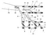
図1,図2,図3において、把持具1は射出成形機2で同時に成形(生産)した16個の小型成形品[ワーク(図示省略)]を一度に把持して取り出すためのもので、射出成形機2の型開きした金型2aに対向するワーク把持位置(図3の実線参照)から射出成形機2外部のワーク解放位置(たとえば、図3の二点鎖線参照)に前記16個の小型成形品を搬送する成形品取出機3の旋回アーム3a先端部に装着される。 1, 2, and 3, a
把持具1は、肉厚tが薄い金属製の板材または硬質合成樹脂製の板材からなり、旋回アーム3aの先端部に装着される基部10と、この基部10に延設された把持部11とを備える。把持部11は、基部10から三つの経路に分岐延出した第1〜第3の枝12,13,14と、第3の枝14からさらに分岐延出した第4〜第6の枝15,16,17および第3の枝14の先端部から二股に分岐延出した第7,第8の枝18,19からなる枝群20によって構成されており、各枝12〜19の横断面形状は長方形に設定されている。 The
枝群20を構成している第1〜第8の枝12〜19には、射出成形機2で同時に成形された16個の小型成形品の成形位置に対応する所定の位置に分散して、16個の小型成形品を一度に把持するための16個の吸着パッド4が取付けられており、各吸着パッド4は、各枝12〜19の体内に設けた吸・送気通路5を介して吸・送気管6に連通し、吸・送気管6は、図示されていない吸・送気切換弁を介して吸・送気手段(図示省略)に接続されている。 The first to
前記構成の把持具1が図3の二点鎖線で示すワーク解放位置にある状態で、成形品取出機3の旋回アーム3aを旋回させて、把持具1を図3の実線で示す位置、つまり射出成形機2の型開きした金型2aに対向するワーク把持位置まで移動させ、さらに把持具1を金型2a、詳しくは可動金型2aに近接させ、ここで前記吸・送気切換弁を切り換えて吸気手段を吸・送気管6に連通させて、該吸・送気管6および吸・送気通路5を負圧化することにより、射出成形機2で同時に成形した16個の小型成形品を16個の吸着パッド4で一度に把持する。 In a state where the
把持具1による16個の小型成形品の吸着把持を終えると、旋回アーム3aを逆方向に旋回させて、把持具1を図3の二点鎖線で示す位置、つまり射出成形機2外部のワーク解放位置まで移動させ、ここで、前記吸・送気切換弁を切り換えて送気手段を吸・送気管6に連通させて、該吸・送気管6および吸・送気通路5を正圧化することで、16個の小型成形品を解放して適宜回収する。 When the gripping and holding of the 16 small molded products by the
把持具1の把持部11が基部10から三つの経路に分岐延出した第1〜第3の枝12,13,14と、第3の枝14からさらに分岐延出した第4〜第6の枝15,16,16および第3の枝14の先端部から二股に分岐延出した第7,第8の枝18,19からなる枝群20によって構成されているので、基部10から最も離れている把持部11の先端部側の重量、つまり、第1〜第8の枝12〜19それぞれの先端部側の重量が小さく(軽く)なる。そのため、把持具1が図3の二点鎖線で示すワーク解放位置から実線で示すワーク把持位置まで移動してここで停止した時の慣性による主として肉厚t方向の振動が抑制されて、振動消失までの時間を短縮することができるので、射出成形機2による小型成形品の成形能率(生産能率)の向上に寄与することができる。 The
本発明に係る把持具1では、前記枝群20を構成している第1〜第8の枝12〜19の長方形横断面積を、基部10側から各枝12〜19の先端部にかけて縮小することで、基部10から最も離れている各枝12〜19の先端部側の重量をさらに小さく(軽く)できる。これにより、把持具1が移動状態から停止した時の慣性による振動をさらに抑制して、振動消失までの時間をより一層短縮することができる。各枝12〜19の横断面積の基部10側から各枝12〜19の先端部にかけての縮小は、各枝12〜19の肉厚tと幅寸法の少なくともいずれか一方を、基部10側から各枝12〜19の先端部にかけて小さく設定することによって実現できる。 In the
図1で説明した把持具1は、図4のように、たとえば、第5の枝16と第6の枝17それぞれの先端部を横桟7で連結してもよい。As shown in FIG.4 , for example, the
このように、第5の枝16と第6の枝17それぞれの先端部を横桟7で連結しても、横桟7および縦桟8自体の重量は軽量であるので、把持部11の延出端の重量増加に影響を及ぼすことはない。そのため、前記第1,第2実施形態と同様の作用効果を奏することができるとともに、横桟7および縦桟8により把持部11の補強効果を高めることができる。 In this way, even if the distal ends of the
前記実施形態では、把持具1を、射出成形機2で同時に成形した多数の小型成形品を一度に把持して取り出すためのものとして説明しているが、薄物ワークと合成樹脂とを一体成形するインサート成形において、薄物ワークを把持して射出成形機2の金型内にインモールドするための把持具1としても適用することができる。In the above-described embodiment, the
前記実施形態では、旋回アーム3aを備えた旋回アーム型の成形品取出機3に把持具1を装着した構成で説明しているが、サイドエントリー型の成形品取出機3に把持具1を装着することもできる。 In the embodiment described above, the
また、前記実施形態では、把持部11の所定位置に吸着パッド4を取付けた構成で説明しているが、吸着パッド4に代えて射出成形機に成形される成形品の挟持が可能な挟持ヘッドを取付けてもよい。挟持ヘッドを取付けた構成であると、吸・送気通路5および吸・送気管6は、図示されていない吸・送気切換弁を介して吸・送気手段(図示省略)に接続することで、挟持ヘッド開閉作動用空気の吸・送気経路として機能することになる。 Moreover, although the said embodiment demonstrated the structure which attached the
1 把持具
2 射出成形機(生産設備)
3 成形品取出機(搬送手段)
4 吸着パッド(把持ヘッド)
10 基部
11 把持部
12〜19 複数の枝
20 枝群1 Gripping
3 Mold take-out machine (conveyance means)
4 Suction pad (gripping head)
DESCRIPTION OF
Claims (1)
Translated fromJapanesePriority Applications (3)
| Application Number | Priority Date | Filing Date | Title |
|---|---|---|---|
| JP2007255673AJP5190838B2 (en) | 2007-09-28 | 2007-09-28 | Gripping tool |
| US12/237,598US7740124B2 (en) | 2007-09-28 | 2008-09-25 | Grasping device |
| EP08017122.6AEP2042453B1 (en) | 2007-09-28 | 2008-09-29 | A grasping device |
Applications Claiming Priority (1)
| Application Number | Priority Date | Filing Date | Title |
|---|---|---|---|
| JP2007255673AJP5190838B2 (en) | 2007-09-28 | 2007-09-28 | Gripping tool |
Publications (2)
| Publication Number | Publication Date |
|---|---|
| JP2009083037A JP2009083037A (en) | 2009-04-23 |
| JP5190838B2true JP5190838B2 (en) | 2013-04-24 |
Family
ID=39917111
Family Applications (1)
| Application Number | Title | Priority Date | Filing Date |
|---|---|---|---|
| JP2007255673AActiveJP5190838B2 (en) | 2007-09-28 | 2007-09-28 | Gripping tool |
Country Status (3)
| Country | Link |
|---|---|
| US (1) | US7740124B2 (en) |
| EP (1) | EP2042453B1 (en) |
| JP (1) | JP5190838B2 (en) |
Families Citing this family (13)
| Publication number | Priority date | Publication date | Assignee | Title |
|---|---|---|---|---|
| JP5190838B2 (en) | 2007-09-28 | 2013-04-24 | 株式会社ユーシン精機 | Gripping tool |
| US8696043B2 (en)* | 2011-11-18 | 2014-04-15 | Nike, Inc. | Hybrid pickup tool |
| US9010827B2 (en) | 2011-11-18 | 2015-04-21 | Nike, Inc. | Switchable plate manufacturing vacuum tool |
| US8849620B2 (en) | 2011-11-18 | 2014-09-30 | Nike, Inc. | Automated 3-D modeling of shoe parts |
| US8858744B2 (en) | 2011-11-18 | 2014-10-14 | Nike, Inc. | Multi-functional manufacturing tool |
| US20140126988A1 (en)* | 2012-11-02 | 2014-05-08 | Shenzhen China Star Optoelectronics Technology Co. Ltd. | Transportation System For Moving Flat Panel And Mechanical Apparatus Thereof And Method For Moving The Same |
| JP2014176926A (en)* | 2013-03-14 | 2014-09-25 | Yaskawa Electric Corp | Robot system and method for conveying work |
| JP5657751B1 (en)* | 2013-07-04 | 2015-01-21 | ファナック株式会社 | Conveying device that sucks and conveys objects |
| CN107512581B (en)* | 2013-11-26 | 2020-08-25 | 科磊股份有限公司 | Pick-and-place head and method for picking up workpieces |
| JP6634435B2 (en)* | 2014-08-05 | 2020-01-22 | コーニング インコーポレイテッド | Robot tools |
| ITUA20162445A1 (en)* | 2016-04-08 | 2017-10-08 | Ct Pack Srl | DEVELOPMENT OF ARTICLES. |
| CN205674219U (en)* | 2016-05-13 | 2016-11-09 | 鄂尔多斯市源盛光电有限责任公司 | Manipulator arm, mechanical hand and bogey |
| DE202017005575U1 (en)* | 2017-10-27 | 2017-11-07 | Heino Ilsemann Gmbh | relocating |
Family Cites Families (20)
| Publication number | Priority date | Publication date | Assignee | Title |
|---|---|---|---|---|
| US4411574A (en)* | 1981-07-13 | 1983-10-25 | Diamond Automations, Inc. | Egg transfer head |
| US4571320A (en)* | 1984-10-31 | 1986-02-18 | General Motors Corporation | Method and apparatus for loading and unloading sheet molding compound in and from a press |
| JP2582270B2 (en)* | 1987-12-09 | 1997-02-19 | 株式会社スター精機 | Automatic removal equipment for molded products |
| JP2958989B2 (en) | 1988-09-30 | 1999-10-06 | ぺんてる株式会社 | Robot hand device and method for mounting a thin work in a mold |
| JPH0727135Y2 (en)* | 1990-05-18 | 1995-06-21 | 株式会社名機製作所 | Unloader for molding machine |
| US6752581B1 (en)* | 1994-06-10 | 2004-06-22 | Johnson & Johnson Vision Care, Inc. | Apparatus for removing and transporting articles from molds |
| IL113694A0 (en)* | 1994-06-10 | 1995-08-31 | Johnson & Johnson Vision Prod | Apparatus for removing and transporting articles from molds |
| JP2770163B2 (en)* | 1996-03-07 | 1998-06-25 | 株式会社ユーシン精機 | Removal head for resin molded products |
| JPH10249771A (en)* | 1997-03-05 | 1998-09-22 | Kanto Auto Works Ltd | Work carrying device for press machine |
| JP3900229B2 (en) | 1998-06-25 | 2007-04-04 | 石川島播磨重工業株式会社 | Board transfer hand |
| DE19901152A1 (en) | 1999-01-14 | 2000-07-20 | Bilsing Automation Gmbh | Workpiece gripper and process for its manufacture |
| JP2002028882A (en)* | 2000-07-14 | 2002-01-29 | Toyota Motor Corp | Handling attachment |
| JP2002067108A (en)* | 2000-09-01 | 2002-03-05 | Yushin Precision Equipment Co Ltd | Molded product removal device |
| JP2004136300A (en)* | 2002-10-16 | 2004-05-13 | Yachiyo Industry Co Ltd | Press line |
| US7128198B2 (en)* | 2002-12-26 | 2006-10-31 | Komatsu Ltd. | Workpiece conveyor for press line |
| FR2856327B1 (en) | 2003-06-17 | 2006-09-29 | A M G | CONNECTING MEMBER BETWEEN A MANIPULATOR AND A PRE-ASSEMBLY OF A PART TO BE REUNIRED |
| KR101142346B1 (en) | 2003-11-21 | 2012-05-18 | 미쓰보시 다이야몬도 고교 가부시키가이샤 | Vacuum suction head, and vacuum suction device and table using the same |
| JP4980712B2 (en) | 2004-04-20 | 2012-07-18 | Jx日鉱日石エネルギー株式会社 | Robot hand member, manufacturing method thereof, and robot hand |
| JP4481864B2 (en)* | 2005-04-14 | 2010-06-16 | 株式会社三協製作所 | Pipe-embedded robot hand and molding method thereof |
| JP5190838B2 (en) | 2007-09-28 | 2013-04-24 | 株式会社ユーシン精機 | Gripping tool |
- 2007
- 2007-09-28JPJP2007255673Apatent/JP5190838B2/enactiveActive
- 2008
- 2008-09-25USUS12/237,598patent/US7740124B2/enactiveActive
- 2008-09-29EPEP08017122.6Apatent/EP2042453B1/ennot_activeCeased
Also Published As
| Publication number | Publication date |
|---|---|
| US7740124B2 (en) | 2010-06-22 |
| EP2042453A1 (en) | 2009-04-01 |
| JP2009083037A (en) | 2009-04-23 |
| US20090084660A1 (en) | 2009-04-02 |
| EP2042453B1 (en) | 2013-04-17 |
Similar Documents
| Publication | Publication Date | Title |
|---|---|---|
| JP5190838B2 (en) | Gripping tool | |
| US8454069B2 (en) | Gripper with adjustable bumper stops | |
| US7887111B2 (en) | Gripper for moving and positioning contact lenses | |
| JP2009012138A (en) | Work gripping robot and work gripping method | |
| CN103611915B (en) | Flexible inlaying and taking clamping device for automobile engine cylinder block | |
| JP5186783B2 (en) | Injection molding apparatus and molding method | |
| CN218747793U (en) | Multi-hole grabbing mechanism for electronic cigarette rods | |
| CN215589798U (en) | An automatic manipulator device for LED lampshade injection molding machine | |
| JPH0929679A (en) | Clamping device | |
| KR102337689B1 (en) | Gripper unit for sand core robot system | |
| JPH06328384A (en) | Hand device | |
| JP7240219B2 (en) | hollow molding machine | |
| CN210334843U (en) | Tongs quick change supporting structure | |
| KR102640419B1 (en) | Gripper for cellular phone protective case transfer | |
| JP4509005B2 (en) | Injection mold and method for producing wax model using the same | |
| CN220409531U (en) | Novel injection molding transformation workpiece taking tool | |
| CN208289918U (en) | A kind of manipulator and glass bending equipment of glass bending equipment | |
| JP4806783B1 (en) | Molded product holding device for automatic injection molded product takeout robot | |
| JP2007144530A (en) | Robot hand | |
| CN221419864U (en) | Feeding device and forming machine | |
| JP3126445U (en) | Gripper device | |
| CN222891263U (en) | Multifunctional round drawing type clamping jaw mechanism | |
| CN222245957U (en) | Demolding adsorption fixture for small plastic products | |
| CN215557087U (en) | Iron core automatic feeding device | |
| JP4307765B2 (en) | Molding auxiliary device and extraction system |
Legal Events
| Date | Code | Title | Description |
|---|---|---|---|
| A621 | Written request for application examination | Free format text:JAPANESE INTERMEDIATE CODE: A621 Effective date:20100924 | |
| A977 | Report on retrieval | Free format text:JAPANESE INTERMEDIATE CODE: A971007 Effective date:20120510 | |
| A131 | Notification of reasons for refusal | Free format text:JAPANESE INTERMEDIATE CODE: A131 Effective date:20120522 | |
| A521 | Request for written amendment filed | Free format text:JAPANESE INTERMEDIATE CODE: A523 Effective date:20120723 | |
| TRDD | Decision of grant or rejection written | ||
| A01 | Written decision to grant a patent or to grant a registration (utility model) | Free format text:JAPANESE INTERMEDIATE CODE: A01 Effective date:20121225 | |
| A61 | First payment of annual fees (during grant procedure) | Free format text:JAPANESE INTERMEDIATE CODE: A61 Effective date:20130122 | |
| R150 | Certificate of patent or registration of utility model | Ref document number:5190838 Country of ref document:JP Free format text:JAPANESE INTERMEDIATE CODE: R150 Free format text:JAPANESE INTERMEDIATE CODE: R150 | |
| FPAY | Renewal fee payment (event date is renewal date of database) | Free format text:PAYMENT UNTIL: 20160208 Year of fee payment:3 | |
| R250 | Receipt of annual fees | Free format text:JAPANESE INTERMEDIATE CODE: R250 | |
| S531 | Written request for registration of change of domicile | Free format text:JAPANESE INTERMEDIATE CODE: R313531 | |
| R350 | Written notification of registration of transfer | Free format text:JAPANESE INTERMEDIATE CODE: R350 | |
| R250 | Receipt of annual fees | Free format text:JAPANESE INTERMEDIATE CODE: R250 | |
| R250 | Receipt of annual fees | Free format text:JAPANESE INTERMEDIATE CODE: R250 |