JP5190565B1 - Shoe sole with slant groove - Google Patents
Shoe sole with slant grooveDownload PDFInfo
- Publication number
- JP5190565B1 JP5190565B1JP2012549196AJP2012549196AJP5190565B1JP 5190565 B1JP5190565 B1JP 5190565B1JP 2012549196 AJP2012549196 AJP 2012549196AJP 2012549196 AJP2012549196 AJP 2012549196AJP 5190565 B1JP5190565 B1JP 5190565B1
- Authority
- JP
- Japan
- Prior art keywords
- oblique
- oblique groove
- midsole
- outsole
- rear foot
- Prior art date
- Legal status (The legal status is an assumption and is not a legal conclusion. Google has not performed a legal analysis and makes no representation as to the accuracy of the status listed.)
- Active
Links
Images


Classifications
- A—HUMAN NECESSITIES
- A43—FOOTWEAR
- A43B—CHARACTERISTIC FEATURES OF FOOTWEAR; PARTS OF FOOTWEAR
- A43B13/00—Soles; Sole-and-heel integral units
- A43B13/14—Soles; Sole-and-heel integral units characterised by the constructive form
- A43B13/22—Soles made slip-preventing or wear-resisting, e.g. by impregnation or spreading a wear-resisting layer
- A43B13/223—Profiled soles
- A—HUMAN NECESSITIES
- A43—FOOTWEAR
- A43B—CHARACTERISTIC FEATURES OF FOOTWEAR; PARTS OF FOOTWEAR
- A43B13/00—Soles; Sole-and-heel integral units
- A43B13/14—Soles; Sole-and-heel integral units characterised by the constructive form
- A—HUMAN NECESSITIES
- A43—FOOTWEAR
- A43B—CHARACTERISTIC FEATURES OF FOOTWEAR; PARTS OF FOOTWEAR
- A43B13/00—Soles; Sole-and-heel integral units
- A43B13/14—Soles; Sole-and-heel integral units characterised by the constructive form
- A43B13/141—Soles; Sole-and-heel integral units characterised by the constructive form with a part of the sole being flexible, e.g. permitting articulation or torsion
Landscapes
- Footwear And Its Accessory, Manufacturing Method And Apparatuses (AREA)
Abstract
Translated fromJapaneseDescription
Translated fromJapanese本発明は斜溝を持つ靴底に関する。 The present invention relates to a shoe sole having an oblique groove.
従来より、斜溝を持つ靴底は公知である。(特許文献1) Conventionally, a shoe sole having an oblique groove has been known. (Patent Document 1)
周知のとおり、靴底は軽量で、踵部の外反を抑制でき、かつ、踵部の衝撃緩衡を図る機能が求められる。
しかし、斜溝を靴底に形成するだけでは前記機能を十分に発揮し得ない。As is well known, a shoe sole is light in weight, can suppress the valgus of the heel, and is required to have a function to reduce the impact of the heel.
However, the above function cannot be sufficiently exhibited only by forming the oblique grooves on the shoe sole.
したがって、本発明の目的は適切な斜溝を形成することで、前記各機能を発揮させることである。 Therefore, an object of the present invention is to exhibit the above functions by forming appropriate oblique grooves.
本発明は、1つの局面において、路面に接地する接地面を持つアウトソール1と、前記アウトソール1の上に配置されたミッドソール2とを備えた靴底において、
前記靴底の後足部Rの中央部および外側部には、前記後足部Rにおいて前記後足部Rの外側の外縁まで斜めの前後方向に延びる斜溝4が形成されており、
母趾球O1と小趾球O5との中点O3と踵の中心O4とを結んだ長軸A2と前記斜溝4の仮想の中心ラインLcとのなす角βが12°〜35°の範囲に設定され、
前記中心ラインLcと前記長軸A2との仮想の交点Oが靴底の前記長軸A2上の全長に対し後端から21%〜43%の範囲に設定され、前記交点Oよりも前方の内側まで延びている。In one aspect, the present invention provides a shoe sole including an
In the center part and the outer part of the rear foot part R of the shoe sole,
The angle β formed by the long axis A2 connecting the midpoint O3 of the main ball O1 and the small ball O5 and the center O4 of the eyelid and the virtual center line Lc of the
An imaginary intersection point O between the center line Lc and the long axis A2 is set within a range of 21% to 43% from the rear end with respect to the total length on the long axis A2 of the shoe sole. It extends to.
本発明は、別の局面において、路面に接地する接地面を持つアウトソール1と、前記アウトソール1の上に配置されたミッドソール2とを備え、前足部F、アーチ部Mおよび後足部Rにおいて足を支持する靴底において、
前記アウトソール1は、前記アーチ部Mを覆わず前記前足部Fおよび後足部Rに分かれて配置され、かつ、前記後足部Rにおいて足の内側INおよび外側OUTの中央部Rcが欠損したU字状に形成され、
前記ミッドソール2は前記後足部Rの前記中央部Rcおよび前記アーチ部Mにおいて露出しており、
前記ミッドソール2の後足部Rの前記中央部Rcおよびアウトソール1の後足部Rの外側部11には、前記後足部Rにおいて前記後足部Rの外側OUTの外縁まで斜めの前後方向に延びる斜溝4が形成されており、
母趾球O1と小趾球O2との中点O3と踵の中心O5とを結んだ長軸A2と前記斜溝4の仮想の中心ラインLcとのなす角βが12°〜35°の範囲に設定され、
前記中心ラインLcと前記長軸A2との仮想の交点Oが前記アーチ部Mの後半部Mbから前記後足部Rの前半部Rfまでの領域に配置されている。In another aspect, the present invention includes an
The
The
The central portion Rc of the rear foot portion R of the
The angle β formed by the long axis A2 connecting the midpoint O3 of the main ball O1 and the small ball O2 and the center O5 of the eyelid and the virtual center line Lc of the
A virtual intersection O between the center line Lc and the long axis A2 is disposed in a region from the rear half Mb of the arch part M to the front half Rf of the rear foot R.
踵部の外反は、距骨下関節軸A1まわりに足が回転する(捩れる)ことにより生じる。前記距骨下関節軸A1は水平面内において、足部の解剖学的な前記長軸A2に対し斜めに傾いている。この傾き角度は、V.T Inman(1969)によれば平均23°で、個人差もあるため±11°程度の幅を持つ。したがって、踵部の外反の抑制には前記23°±11°に傾いた距骨下関節軸A1まわりの回転が小さくなるよう、ソールのねじれ剛性を保つことが重要である。The hallux valgus is caused by the rotation (twisting) of the foot around the subtalar joint axis A1. The subtalar joint axis A1 is inclined with respect to the anatomical long axis A2 of the foot in a horizontal plane. This angle of inclination According to T Inman (1969), it has an average of 23 ° and has a width of about ± 11 ° due to individual differences. Therefore, it is important to maintain the torsional rigidity of the sole so as to reduce the rotation around the subtalar joint axis A1 inclined to 23 ° ± 11 ° in order to suppress the valgus of the hip.
一般に、ねじりの軸上に溝が存在しても、その軸まわりでのねじれ剛性は溝がない場合と殆ど変わらない。そのため、本発明では斜溝4の存在により距骨下関節軸A1のまわりの剛性は殆ど低下せず、ねじれに対する安定性が保たれる。In general, even if a groove exists on the axis of torsion, the torsional rigidity around the axis is almost the same as when there is no groove. Therefore, in the present invention, the rigidity around the subtalar joint axis A1 is hardly lowered due to the presence of the
しかし、距骨下関節軸A1の位置をソールの形状から特定することは著しい困難を伴う。そこで、本発明においては、距骨下関節軸A1で発明を定義せずに、斜溝4のソールに対する位置、つまり前記交点Oの位置で定義した。 However, it is extremely difficult to specify the position of the subtalar joint axis A1 from the shape of the sole. Therefore, in the present invention, the invention is not defined by the subtalar joint axis A1, but is defined by the position of the
すなわち、1つの局面においては、前記交点Oの位置を靴底の後端からの寸法で定義し、一方、別の局面においては、前記交点Oの位置を靴底のアーチ部Mおよび後足部Rにおける位置によって定義した。That is, in one aspect, the position of the intersection point O is defined by a dimension from the rear end of the shoe sole, while in another aspect, the position of the intersection point O is defined as the arch portion M and the rear foot portion of the shoe sole. Defined by position in R.
本明細書において、アーチ部Mとはアウトソール1が設けられていない中足の部位をいい、後足部Rとはアーチ部Mよりも後方の部位をいう。In the present specification, the arch portion M refers to a portion of the middle foot where the
本発明では斜溝4がソールの後足外側の外周まで達している。そのため、後足外側におけるソールの圧縮剛性は低下するものと考えられる。踵は後足外側から接地するが、踵が接地した直後には斜溝4がない場合に比べると、後足の外側が大きく圧縮変形し、ソール上面が傾くことが予想される。この傾きは外反とは反対の傾きであり、それにより、踵部の外反角度は、斜溝4がない場合に比較して小さいであろう。In the present invention, the
また、前記後足外側の大きな変形により、衝撃緩衝性も向上する。
また、アウトソール1の欠損した中央部Rcおよびアーチ部Mに加え、距骨下関節軸A1に沿った斜溝4により、ソールの軽量化が図られる。Further, the shock buffering property is improved due to the large deformation on the outer side of the rear foot.
Further, in addition to the missing central portion Rc and arch portion M of the
したがって、軽量化を実現しつつ、踵部の外反を抑制し、かつ、踵部の衝撃緩衝も向上する。Therefore, while reducing the weight, the valgus of the buttock is suppressed and the shock buffering of the buttock is improved.
ここで、クレームされた斜溝4の配置により、斜溝4は、U字状(馬蹄形)のアウトソール1の後足部の外側を12°〜35°の角βで斜めに横切る。そのため、U字状で面積の小さいアウトソール1の外側における前記斜溝4の長さが長い。すなわち、U字状で面積の小さいアウトソール1に長い斜溝4が形成されている。したがって、前記軽量で、外反抑制および衝撃緩衝の効果が高い。Here, due to the claimed arrangement of the
前記角βは本来23°に設定されるべきところ、当該23°では斜溝4の前端が母趾球O1の近傍に向かって延び、そのため、前足部Fの内側に斜溝4が形成される。そのような事態を避けるため角βは20°〜35°程度が好ましいかもしれない。なお、角βを23°+11°=34°よりも1°大きい35°以下とした理由は測定誤差を考慮したためである。The angle β should originally be set to 23 °. At the 23 °, the front end of the
また、アウトソール1は後足部Rの中央部Rcが欠損したU字状であるから、中央部Rcが欠損していることによっても前記軽量化が図られる。ここで、前記中央部Rcにはミッドソール2に斜溝4が形成されている。したがって、ミッドソール2も前記ねじれ剛性に寄与しつつ、前記軽量化等が図られる。Further, since the
好ましくは、前記斜溝4は前記交点Oよりも前方の前方部4Fと、前記交点Oよりも後方の後方部4Bと有し、
前記後方部4Bの斜溝4の容積が前記前方部4Fの斜溝4の容積よりも大きい。Preferably, the
The volume of the
この場合、斜溝4の容積が大きい後方部4Bにおいては比較的変形が大きく、ミッドソール2の上面が沈み易く、したがって、着地のファーストストライクの衝撃を緩衡し易い。一方、斜溝4の容積が小さい前方部4Fにおいてはミッドソール2の上面が沈みにくく、足のアーチの内側で重心が滞留しにくい。 In this case, the
好ましくは、斜溝4は靴底の内側の縁まで延びていない。
この場合、ミッドソール2はアーチ部Mないし中足部において上面が沈みにくいだろう。Preferably, the
In this case, the upper surface of the
好ましくは、アウトソール1の斜溝4は斜後方に向かって末広がりに形成される。
この場合、前述と同様にファーストストライクの衝撃を緩衡し易く、かつ、足のアーチの内側で重心が滞留しにくい。Preferably, the
In this case, as described above, it is easy to relax the impact of the first strike, and the center of gravity hardly stays inside the foot arch.
好ましくは、前記斜溝4に直交する方向に延びる横断溝5を更に備える。
かかる横断溝5はアウトソール1を足の外側において分断し、足の外側におけるアウトソール1やミッドソール2の変形を促すだろう。Preferably, a
Such
好ましくは、前記アウトソール1は、前足部Fと後足部Rとの間のアーチ部Mを覆わず前足部Fおよび後足部Rに分かれて配置され、
前記ミッドソール2のアーチ部Mの下面には樹脂の非発泡体で形成された強化部材3が付着されており、
前記強化部材3は前記斜溝4と概ね平行に延びる斜め部31を有し、この斜め部31は前記斜溝4の前方において前記斜溝4に接近して配置されている。Preferably, the
A reinforcing
The reinforcing
この場合、アーチ部Mまたはその近傍の斜溝4によるアーチ部Mの低下を強化部材3の斜め部31で抑制できるだろう。In this case, a decrease in the arch portion M due to the arch portion M or the
好ましくは、前記仮想の交点Oの位置が前記中央部Rcの図心Gよりも前方に配置されている。
かかる配置により、斜溝4が距骨下関節軸A1上またはその近傍に配置される。Preferably, the position of the virtual intersection point O is disposed in front of the centroid G of the central portion Rc.
With this arrangement, the
好ましくは、前記ミッドソール2の後足部Rの中央部Rcに形成された斜溝4は一対の互いに対面する第1および第2の縁のラインL1,L2で定義され、
前記アウトソール1に形成された斜溝4は、一対の互いに対面する第3および第4の縁のラインL3,L4で定義され、
前記第3および第4の縁のラインL3,L4が、それぞれ、前記第1および第2の縁のラインL1,L2に概ね平行であるか、あるいは、第1および第2の縁のラインL1,L2が形成する角よりも大きな角で末広がりに形成されている。Preferably, the
The
The third and fourth edge lines L3, L4 are generally parallel to the first and second edge lines L1, L2, respectively, or the first and second edge lines L1, L2, respectively. It is formed so as to widen at the corner larger than the corner formed by L2.
この場合、ミッドソール2とアウトソール1の斜溝4が協働し、本発明の効果が高まる。In this case, the
好ましくは、前記斜溝4は前記アーチ部Mのミッドソール2の内側部20にまで延びて形成され、前記アーチ部Mの斜溝4の前記中心ラインLcに直交する横断面積の平均値は前記ミッドソール2の後足部Rの中央部Rcの斜溝4のそれよりも小さい。Preferably, the
好ましくは、前記斜溝4は前記アーチ部Mのミッドソール2の内側部20の縁まで延びておらず、かつ、前記アーチ部Mの前端よりも後方に前記斜溝4の先端が配置されている。Preferably, the
これらの場合、アーチ部Mの内側において斜溝4の横断面積が小さいか、あるいは、斜溝4がアーチ部Mの内側の縁まで延びておらず、アーチ部Mの内側におけるミッドソール上面の沈下が小さい。そのため、足の外反を抑制し得ると共に、重心がアーチ部Mの内側において滞留したりするのを抑制し得る。In these cases, the cross-sectional area of the
好ましくは、前記アウトソール1の斜溝4は後方に向かって末広がりに形成されている。Preferably, the
好ましくは、前記斜溝4に対し、直交する横断溝を更に備える。Preferably, a transverse groove orthogonal to the
好ましくは、前記ミッドソール2のアーチ部Mの下面には樹脂の非発泡体で形成された強化部材3が付着されており、
前記強化部材3は前記斜溝4と概ね平行に延びる斜め部31を有し、この斜め部31は前記斜溝4の前方において前記斜溝4に接近して配置されている。Preferably, a reinforcing
The reinforcing
この場合、アーチ部Mまたはその近傍の斜溝4によるアーチ部Mの低下を強化部材3の斜め部31で抑制できるだろう。In this case, a decrease in the arch portion M due to the arch portion M or the
好ましくは、前記斜め部31は前記前足部Fまで延びている。
この場合、過度なソールの屈曲を防ぎ、効率的な走行が可能となる。Preferably, the
In this case, excessive bending of the sole is prevented, and efficient traveling is possible.
好ましくは、前記強化部材3は前記アーチ部Mにおいて前記ミッドソール2の外側に沿って延びる外側部32を更に備え、
前記外側部32と前記斜め部31との間において前記ミッドソール2の下面が露出する。
この場合、強化部材3の軽量化を図り得る。Preferably, the reinforcing
The lower surface of the
In this case, the weight of the reinforcing
本発明はある局面において、路面に接地する接地面を持つアウトソール1と、前記アウトソール1の上に配置されたミッドソール2とを備え、前足部F、アーチ部Mおよび後足部Rにおいて足を支持する靴底において、
前記アウトソール1は、前記アーチ部Mを覆わず前記前足部Fおよび後足部Rに分かれて配置され、
前記ミッドソール2およびアウトソール1には、前記後足部Rにおいて前記後足部Rの外側の外縁まで斜めの前後方向に延びる斜溝4が形成されており、
母趾球O1と小趾球O5との中点O3と踵の中心とを結んだ長軸A2と前記斜溝4の仮想の中心ラインLcとのなす角βが12°〜35°の範囲に設定され、
前記中心ラインLcと前記長軸A2との仮想の交点Oが前記アーチ部Mの後半部Mbから前記後足部Rの前半部Rfまでの領域に配置され、
前記ミッドソール2のアーチ部Mの下面には樹脂の非発泡体で形成された強化部材3が付着されており、
前記強化部材3は前記斜溝4と概ね平行に延びる斜め部31を有し、この斜め部31は前記斜溝4の前方において前記斜溝4に接近して配置されている。In one aspect, the present invention includes an
The
The
The angle β formed by the long axis A2 connecting the midpoint O3 of the main ball O1 and the small ball O5 and the center of the eyelid and the virtual center line Lc of the
An imaginary intersection O between the center line Lc and the long axis A2 is disposed in a region from the rear half Mb of the arch M to the front half Rf of the rear foot R,
A reinforcing
The reinforcing
この局面においては、アーチ部Mまたはその近傍の斜溝4によるアーチ部Mの低下を強化部材3の斜め部31で抑制できるだろう。In this aspect, a decrease in the arch portion M due to the arch portion M or the
好ましくは、前記斜め部31は前記前足部Fまで延びている。
この場合、過度なソールの屈曲を防ぎ、効率的な走行が可能となる。Preferably, the
In this case, excessive bending of the sole is prevented, and efficient traveling is possible.
好ましくは、前記強化部材3は前記アーチ部Mにおいて前記ミッドソール2の外側に沿って延びる外側部32を更に備え、
前記外側部32と前記斜め部31との間において前記ミッドソール2の下面が露出する。
この場合、強化部材3の軽量化が図られる。Preferably, the reinforcing
The lower surface of the
In this case, the weight of the reinforcing
本発明は、添付の図面を参考にした以下の好適な実施例の説明からより明瞭に理解されるであろう。しかしながら、実施例および図面は単なる図示および説明のためのものであり、本発明の範囲を定めるために利用されるべきものではない。本発明の範囲は請求の範囲によってのみ定まる。添付図面において、複数の図面における同一の部品番号は、同一または相当部分を示す。The invention will be more clearly understood from the following description of preferred embodiments with reference to the accompanying drawings, in which: However, the examples and figures are for illustration and description only and should not be used to define the scope of the present invention. The scope of the present invention is defined only by the claims. In the accompanying drawings, the same part numbers in a plurality of drawings indicate the same or corresponding parts.
以下、本発明の一実施例が図面にしたがって説明される。
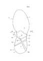
図1および図2に示すように、靴底はアウトソール1およびミッドソール2を備えている。なお、図1〜図5においてはアウトソール1の接地面に形成された微細な溝(いわゆる意匠)は、省略されている。Hereinafter, an embodiment of the present invention will be described with reference to the drawings.
As shown in FIGS. 1 and 2, the shoe sole includes an
図3の規則正しい網点で示すように、アウトソール1は前足部Fおよび後足部Rに配置されている。アウトソール1は例えばゴムの発泡体又は非発泡体で形成され、路面と接する接地面1s(図7A)を有している。なお、図3において、アウトソール1には規則正しい大きい網点が施されている。As shown by the regular halftone dots in FIG. 3, the
ミッドソール2は、例えばEVAなどの樹脂の発泡体で形成され、図2に示すように、アウトソール1の上に配置され、着地の衝撃を緩和するものである。そのため、ミッドソール2はアウトソール1よりも厚く形成されている。The
図1〜図3に示すように、ミッドソール2の下面2u(図7A)には、後述する斜溝4および横断溝5が設けられ、複数個のパーツに分離された前記アウトソール1が設けられている。これらの図に示すように、前記ミッドソール2は後足部Rの中央部Rcおよび/またはアーチ部Mにおいて露出していてもよい。As shown in FIGS. 1 to 3, the
図3に明示するように、前記アウトソール1は、前記アーチ部Mを覆わず前記前足部Fおよび後足部Rに分かれて配置され、かつ、前記後足部Rにおいて中央部Rcが欠損したU字状に形成されている。すなわち、後足部Rの中央部Rcにはミッドソール2の表面にアウトソール1が設けられていない。As shown in FIG. 3, the
ここで、「アウトソール1の中央部Rcが欠損したU字状」とは、アウトソール1が複数の斜溝4および横断溝5により後足部Rにおいて複数のパーツに分離されていることを含み、更に、中央部Rcにはアウトソール1が設けられておらず、かつ、後足部Rの前端においてアウトソール1が斜溝4で内外に分断されていることを意味する。
なお、中央部Rcのだ円形状の領域においてミッドソール2は若干、凹んでいてもよい。Here, “the U-shape in which the center portion Rc of the
Note that the
図1〜図3において、前記斜溝4および横断溝5の底面には規則正しくない細かい網点が施されている。
ミッドソール2のアーチ部Mの内側部20、前記ミッドソール2の後足部Rの中央部Rcおよびアウトソール1の外側部11において、斜溝4は前記アーチ部Mの内側INの内縁から前記後足部Rの外側OUTの外縁まで斜めの前後方向に延びる。1 to 3, the bottom surfaces of the
In the
前記斜溝4の前記中央部Rcにおける最深部の深さは、例えば、5mm〜10mm程度が好ましく、また、前記斜溝4の前記外側部11における最深部の深さは、例えば、5mm〜15mm程度が好ましい。深さが小さすぎると軽量化などの効果が十分に得られず、一方、深さが大きすぎると足の安定した支持が得られないからである。The depth of the deepest portion in the central portion Rc of the
前記斜溝4の前記中央部Rcにおける幅は、横断溝5の部位を除くと、例えば、5mm〜15mm程度が好ましい。溝の幅が大きすぎると、ねじれ剛性の低下が大きくなり、一方、溝の幅が小さいと軽量化などの効果が得られないからである。The width of the
図9に示すように、斜溝4はアーチ部Mにおいて内側INの内縁まで延びていなくてもよい。前記斜溝4が前記アーチ部Mのミッドソール2の内側部20まで延びていない場合、前記アーチ部Mまたは前記後足部Rの前端よりも後方に前記斜溝4の前端が配置されていてもよい。As shown in FIG. 9, the
図6において、距骨下関節軸A1と長軸A2とのなす角αは23°±11°であるといわれている。ここで、前記長軸A2は、母趾球O1の中心と小趾球O5の中心との中点O3と踵の中心O4とを結んだ直線で表される。
一方、前記距骨下関節軸A1は距骨頭O6と踵骨外側結節O7とを結んだ直線で表される。In FIG. 6, it is said that the angle α formed by the subtalar joint axis A1 and the long axis A2 is 23 ° ± 11 °. Here, the major axis A2 is represented by a straight line connecting a center point O3 between the center of the main ball O1 and the center of the small ball O5 and the center O4 of the eyelid.
On the other hand, the subtalar joint axis A1 is represented by a straight line connecting the head of the talus O6 and the outer radial joint O7.
前記斜溝4は前記距骨下関節軸A1に沿って形成されている。すなわち、図5の前記長軸A2と前記斜溝4の仮想の中心ラインLcとのなす角βは12°〜35°の範囲に設定され、たとえば本実施例の場合、約30°に設定されている。The
前記中心ラインLcと前記長軸A2との仮想の交点Oは、前記アーチ部Mの後半部から前記後足部Rの前半部Rfまでの領域に配置されている。これを寸法的な割合で表すと、図5の前記仮想の交点Oは靴底の前記長軸A2上の全長に対し後端から21%〜43%の範囲に設定されている。前記斜溝4は前記交点Oよりも前方の内側および後方の外側まで延びている。An imaginary intersection O between the center line Lc and the long axis A2 is arranged in a region from the second half of the arch part M to the front half Rf of the rear foot part R. Expressing this in a dimensional ratio, the virtual intersection point O in FIG. 5 is set in a range of 21% to 43% from the rear end with respect to the total length of the sole on the long axis A2. The
本実施例の場合、前記仮想の交点Oの位置は後足部Rの中央部Rcに設けられ、かつ、前記中央部Rcの図心Gよりも前方に配置されている。かかる配置により、斜溝4が距骨下関節軸A1(図6)上に配置される。なお、図心Gとは中央部Rcの平面図形の中心をいう。In the case of the present embodiment, the position of the virtual intersection point O is provided at the center portion Rc of the rear foot R and is disposed in front of the centroid G of the center portion Rc. With this arrangement, the
前記斜溝4は前記交点Oよりも前方の前方部4Fと、前記交点Oよりも後方の後方部4Bとを有する。前記後方部4Bの斜溝4の容積Vbは前記前方部4Fの斜溝4の容積Vfよりも大きい。The
ここで、斜溝4の容積Vb,Vfは斜溝4の横断面積に斜溝4の当該部位の長さを積分した値となる。したがって、例えば前記アーチ部Mの斜溝4は浅くなっており、前記中心ラインLcに直交する横断面積の平均値については図8A〜図8Cに示すように、前記アーチ部Mの斜溝4の横断面積の平均値は、前記ミッドソール2の後足部Rの中央部Rcの斜溝4のそれよりも小さい。Here, the volumes Vb and Vf of the
本実施例の場合、図2のアーチ部Mにおいて斜溝4の深さは斜め前方に延びるに従い徐々に浅くなっている。また、図7Aの後足部Rの中央部Rcにおいて斜溝4の断面積が最も大きく、図7Bの後足部Rの後方では斜溝4の断面積が若干小さくてもよい。In the case of the present embodiment, the depth of the
図5において、前記ミッドソール2の後足部Rの中央部Rcに形成された斜溝4は一対の互いに平行で対面する第1および第2の縁のラインL1,L2で定義される。一方、前記アウトソール1に形成された斜溝4は、一対の互いに平行で対面する第3および第4の縁のラインL3,L4で定義される。In FIG. 5, the
本実施例の場合、前記第3および第4の縁のラインL3,L4は、それぞれ、前記第1および第2の縁のラインL1,L2に概ね平行であるが、図9に示すように第1および第2の縁のラインL1,L2が形成する角よりも大きな角で末広がりに形成されていてもよい。すなわち、前記アウトソール1の外側部11の斜溝4は斜後方に向かって末広がりに形成されていてもよい。In the present embodiment, the third and fourth edge lines L3 and L4 are substantially parallel to the first and second edge lines L1 and L2, respectively. However, as shown in FIG. The first and second edge lines L <b> 1 and L <b> 2 may be formed wider than the corner formed by the corners. That is, the
図5の前記横断溝5は斜溝4に対し直交する方向に延びており、本実施例の場合、横断溝5は斜溝4に直交するように配置されているが、横断溝5と斜溝4となす角は、70°〜90°程度に設定されていてもよい。The
前記横断溝5はU字状のアウトソール1の内側部10および外側部11において、前記アウトソール1を複数個に分離している。なお、図9に示すように、前記横断溝5は内側INから外側OUTに延びるに従い幅広に形成されていてもよい。The
図4の網点で示すように、前記ミッドソール2のアーチ部Mの下面には樹脂の非発泡体で形成された強化部材3が付着されている。前記強化部材3は前記斜溝4と概ね平行に延びる斜め部31を有し、この斜め部31は前記斜溝4の前方において前記斜溝4に接近して配置されている。前記斜め部31はアーチ部Mから前足部Fの少なくとも後端まで延びていてもよい。As shown by the halftone dots in FIG. 4, a reinforcing
前記強化部材3は前記アーチ部Mにおいて前記ミッドソール2の外側に沿って延びる外側部32を更に備える。前記外側部32と前記斜め部31との間において前記ミッドソール2の下面である露出部22が露出する。The reinforcing
前記斜め部31と外側部32との間には両者31,32を連結する連結部33が架設されている。すなわち前記ミッドソール2の露出部22は前記斜め部31、外側部32および連結部33に囲まれた領域において露出している。Between the
前記斜め部31は斜溝4の上方において斜溝4に沿って配置されていればよく、したがって、図9のように、アーチ部Mの概ね全域を覆う強化部材3にも斜め部31が存在する。The
以上のとおり、図面を参照しながら好適な実施例を説明したが、当業者であれば、本明細書を見て、自明な範囲で種々の変更および修正を容易に想定するであろう。
たとえば、アウトソール1は前足部Fから後足部Rまでの概ね全長にわたって、かつ、全域に設けられていてもよい。更に、アーチ部Mや後足部Rにおいてミッドソール2は露出していなくてもよい。強化部材3や横断溝5は設けなくてもよい。
したがって、そのような変更および修正は、請求の範囲から定まる本発明の範囲内のものと解釈される。As described above, the preferred embodiments have been described with reference to the drawings. However, those skilled in the art will readily understand various changes and modifications within the obvious scope by looking at the present specification.
For example, the
Accordingly, such changes and modifications are to be construed as within the scope of the present invention as defined by the claims.
本発明はランニングなどの種々のアスレチックシューズに利用できる。 The present invention can be used for various athletic shoes such as running.
1:アウトソール 1s:接地面 10:内側部 11:外側部
2:ミッドソール 2u:下面 20:内側部 22:露出部
3:強化部材 31:斜め部 32:外側部 33:連結部
4:斜溝 4F:前方部 4B:後方部
5:横断溝
A1:距骨下関節軸 A2:長軸
Lc:中心ライン L1〜L4:第1〜第4ライン
F:前足部
R:後足部 Rc:中央部 Rf:前半部
M:アーチ部 Mb:後半部
O:交点
O1:母趾球 O2:小趾球
IN:内側 OUT:外側
α,β:角
1:
5: Transverse groove A1: Subtalar joint axis A2: Long axis Lc: Center line L1-L4: First to fourth lines F: Forefoot
R: Rear foot part Rc: Center part Rf: Front half part M: Arch part Mb: Second half part O: Intersection point O1: Ryukyu ball O2: Ryukyu ball IN: Inside OUT: Outside α, β: Corner
Claims (19)
Translated fromJapanese前記靴底の後足部Rの中央部および外側部には、前記後足部Rにおいて前記後足部Rの外側の外縁まで斜めの前後方向に延びる斜溝4が形成されており、
母趾球O1と小趾球O5との中点O3と踵の中心O4とを結んだ長軸A2と前記斜溝4の仮想の中心ラインLcとのなす角βが12°〜35°の範囲に設定され、
前記中心ラインLcと前記長軸A2との仮想の交点Oが靴底の前記長軸A2上の全長に対し後端から21%〜43%の範囲に設定され、前記交点Oよりも前方の内側まで延びている。In a shoe sole comprising an outsole 1 having a ground contact surface that contacts the road surface, and a midsole 2 disposed on the outsole 1,
In the center part and the outer part of the rear foot part R of the shoe sole, oblique grooves 4 extending in the front-rear direction to the outer edge of the rear foot part R in the rear foot part R are formed,
The angle β formed by the long axis A2 connecting the midpoint O3 of the main ball O1 and the small ball O5 and the center O4 of the eyelid and the virtual center line Lc of the oblique groove 4 is in the range of 12 ° to 35 °. Set to
An imaginary intersection point O between the center line Lc and the long axis A2 is set within a range of 21% to 43% from the rear end with respect to the total length on the long axis A2 of the shoe sole. It extends to.
前記後方部4Bの斜溝4の容積が前記前方部4Fの斜溝4の容積よりも大きい。The shoe sole according to claim 1, wherein the oblique groove 4 has a front part 4F in front of the intersection O and a rear part 4B in the rear of the intersection O,
The volume of the oblique groove 4 in the rear part 4B is larger than the volume of the oblique groove 4 in the front part 4F.
前記アウトソール1は、前足部Fと前記後足部Rとの間のアーチ部Mを覆わず前記前足部Fおよび前記後足部Rに分かれて配置され、
前記ミッドソール2のアーチ部Mの下面には樹脂の非発泡体で形成された強化部材3が付着されており、
前記強化部材3は前記斜溝4と概ね平行に延びる斜め部31を有し、この斜め部31は前記斜溝4の前方において前記斜溝4に接近して配置されている。In the shoe sole of any one of Claims 1-5,
The outsole 1 is arranged so as to be divided into the front foot portion F and the rear foot portion R without covering the arch portion M between the front foot portion F and the rear foot portion R,
A reinforcing member 3 made of a resin non-foam is attached to the lower surface of the arch portion M of the midsole 2;
The reinforcing member 3 has an oblique portion 31 extending substantially parallel to the oblique groove 4, and the oblique portion 31 is disposed in front of the oblique groove 4 and close to the oblique groove 4.
前記アウトソール1は、前記アーチ部Mを覆わず前記前足部Fおよび後足部Rに分かれて配置され、かつ、前記後足部Rにおいて足の内側INおよび外側OUTの中央部Rcが欠損したU字状に形成され、
前記ミッドソール2は前記後足部Rの前記中央部Rcおよび前記アーチ部Mにおいて露出しており、
前記ミッドソール2の後足部Rの前記中央部Rcおよびアウトソール1の後足部Rの外側部11には、前記後足部Rにおいて前記後足部Rの外側OUTの外縁まで斜めの前後方向に延びる斜溝4が形成されており、
母趾球O1と小趾球O2との中点O3と踵の中心O5とを結んだ長軸A2と前記斜溝4の仮想の中心ラインLcとのなす角βが12°〜35°の範囲に設定され、
前記中心ラインLcと前記長軸A2との仮想の交点Oが前記アーチ部Mの後半部Mbから前記後足部Rの前半部Rfまでの領域に配置されている。In a shoe sole that includes an outsole 1 having a ground contact surface that contacts a road surface and a midsole 2 disposed on the outsole 1 and supports a foot at a front foot part F, an arch part M, and a rear foot part R ,
The outsole 1 is arranged so as not to cover the arch part M and is divided into the front foot part F and the rear foot part R, and the rear foot part R lacks the central part Rc of the inner side IN and the outer side OUT of the foot. Formed in a U-shape,
The midsole 2 is exposed at the central portion Rc and the arch portion M of the rear foot R,
The central portion Rc of the rear foot portion R of the midsole 2 and the outer portion 11 of the rear foot portion R of the outsole 1 are slanted back and forth at the rear foot portion R to the outer edge of the outer side OUT of the rear foot portion R. Oblique grooves 4 extending in the direction are formed,
The angle β formed by the long axis A2 connecting the midpoint O3 of the main ball O1 and the small ball O2 and the center O5 of the eyelid and the virtual center line Lc of the oblique groove 4 is in the range of 12 ° to 35 °. Set to
A virtual intersection O between the center line Lc and the long axis A2 is disposed in a region from the rear half Mb of the arch part M to the front half Rf of the rear foot R.
前記アウトソール1に形成された前記斜溝4は、一対の互いに対面する第3および第4の縁のラインL3,L4で定義され、
前記第3および第4の縁のラインL3,L4が、それぞれ、前記第1および第2の縁のラインL1,L2に概ね平行であるか、あるいは、前記第1および第2の縁のラインL1,L2が形成する角よりも大きな角で末広がりに形成されている。The shoe according to claim 8, wherein the oblique groove 4 formed in the central portion Rc of the rear foot portion R of the midsole 2 is defined by a pair of first and second edge lines L1 and L2 facing each other.
The oblique groove 4 formed in the outsole 1 is defined by a pair of third and fourth edge lines L3 and L4 facing each other,
The third and fourth edge lines L3 and L4 are generally parallel to the first and second edge lines L1 and L2, respectively, or the first and second edge lines L1. , L <b> 2 is formed with a larger angle than the angle formed by L <b> 2.
前記強化部材3は前記斜溝4と概ね平行に延びる斜め部31を有し、この斜め部31は前記斜溝4の前方において前記斜溝4に接近して配置されている。The shoe sole according to any one of claims 7 to 13, wherein a reinforcing member 3 formed of a non-foamed resin is attached to the lower surface of the arch portion M of the midsole 2,
The reinforcing member 3 has an oblique portion 31 extending substantially parallel to the oblique groove 4, and the oblique portion 31 is disposed in front of the oblique groove 4 and close to the oblique groove 4.
前記外側部32と前記斜め部31との間において前記ミッドソール2の下面が露出する。The sole according to claim 15, wherein the reinforcing member 3 further includes an outer portion 32 extending along an outer edge of the midsole 2 in the arch portion M,
The lower surface of the midsole 2 is exposed between the outer portion 32 and the oblique portion 31.
前記アウトソール1は、前記アーチ部Mを覆わず前記前足部Fおよび前記後足部Rに分かれて配置され、
前記ミッドソール2および前記アウトソール1には、前記後足部Rにおいて前記後足部Rの外側の外縁まで斜めの前後方向に延びる斜溝4が形成されており、
母趾球O1と小趾球O5との中点O3と踵の中心とを結んだ長軸A2と前記斜溝4の仮想の中心ラインLcとのなす角βが12°〜35°の範囲に設定され、
前記中心ラインLcと前記長軸A2との仮想の交点Oが前記アーチ部Mの後半部Mbから前記後足部Rの前半部Rfまでの領域に配置され、
前記ミッドソール2のアーチ部Mの下面には樹脂の非発泡体で形成された強化部材3が付着されており、
前記強化部材3は前記斜溝4と概ね平行に延びる斜め部31を有し、この斜め部31は前記斜溝4の前方において前記斜溝4に接近して配置されている。In a shoe sole that includes an outsole 1 having a ground contact surface that contacts a road surface and a midsole 2 disposed on the outsole 1 and supports a foot at a front foot part F, an arch part M, and a rear foot part R ,
The outsole 1 is arranged so as not to cover the arch part M and to be divided into the front foot part F and the rear foot part R,
The midsole 2 and the outsole 1 are formed with oblique grooves 4 extending obliquely in the front-rear direction to the outer edge of the rear foot R at the rear foot R,
The angle β formed by the long axis A2 connecting the midpoint O3 of the main ball O1 and the small ball O5 and the center of the eyelid and the virtual center line Lc of the oblique groove 4 is in the range of 12 ° to 35 °. Set,
An imaginary intersection O between the center line Lc and the long axis A2 is disposed in a region from the rear half Mb of the arch M to the front half Rf of the rear foot R,
A reinforcing member 3 made of a resin non-foam is attached to the lower surface of the arch portion M of the midsole 2;
The reinforcing member 3 has an oblique portion 31 extending substantially parallel to the oblique groove 4, and the oblique portion 31 is disposed in front of the oblique groove 4 and close to the oblique groove 4.
前記外側部32と前記斜め部31との間において前記ミッドソール2の下面が露出する。The reinforcement member 3 according to claim 18, further comprising an outer portion 32 extending along the outer side of the midsole 2 in the arch portion M,
The lower surface of the midsole 2 is exposed between the outer portion 32 and the oblique portion 31.
Applications Claiming Priority (1)
| Application Number | Priority Date | Filing Date | Title |
|---|---|---|---|
| PCT/JP2012/062010WO2013168259A1 (en) | 2012-05-10 | 2012-05-10 | Shoe soles having inclined grooves |
Publications (2)
| Publication Number | Publication Date |
|---|---|
| JP5190565B1true JP5190565B1 (en) | 2013-04-24 |
| JPWO2013168259A1 JPWO2013168259A1 (en) | 2015-12-24 |
Family
ID=48481492
Family Applications (1)
| Application Number | Title | Priority Date | Filing Date |
|---|---|---|---|
| JP2012549196AActiveJP5190565B1 (en) | 2012-05-10 | 2012-05-10 | Shoe sole with slant groove |
Country Status (4)
| Country | Link |
|---|---|
| US (1) | US20150135558A1 (en) |
| EP (1) | EP2848142B1 (en) |
| JP (1) | JP5190565B1 (en) |
| WO (1) | WO2013168259A1 (en) |
Cited By (3)
| Publication number | Priority date | Publication date | Assignee | Title |
|---|---|---|---|---|
| JP2014008298A (en)* | 2012-06-30 | 2014-01-20 | Asahi Corp | Shoe sole |
| USD788427S1 (en)* | 2016-02-14 | 2017-06-06 | Nike, Inc. | Shoe outsole |
| US10548369B2 (en) | 2014-04-11 | 2020-02-04 | Asics Corporation | Shoe sole |
Families Citing this family (57)
| Publication number | Priority date | Publication date | Assignee | Title |
|---|---|---|---|---|
| EP2848144B1 (en) | 2012-05-10 | 2020-04-29 | ASICS Corporation | Sole provided with outer sole and midsole |
| USD722427S1 (en)* | 2012-05-16 | 2015-02-17 | Under Armour, Inc. | Shoe bottom |
| EP2974614B1 (en) | 2013-03-15 | 2022-05-04 | ASICS Corporation | Midsole having a laminated structure |
| USD734008S1 (en)* | 2013-03-22 | 2015-07-14 | Reebok International Limited | Shoe |
| WO2014178137A1 (en) | 2013-05-01 | 2014-11-06 | 株式会社アシックス | Member for shoe sole |
| US20140325876A1 (en)* | 2013-05-02 | 2014-11-06 | Wolverine World Wide, Inc. | Sole assembly for article of footwear |
| US9833039B2 (en)* | 2013-09-27 | 2017-12-05 | Nike, Inc. | Uppers and sole structures for articles of footwear |
| US10159306B2 (en) | 2013-10-10 | 2018-12-25 | Asics Corporation | Shoe sole |
| JP6055554B2 (en) | 2013-10-10 | 2016-12-27 | 株式会社アシックス | Shoe sole |
| US9615626B2 (en)* | 2013-12-20 | 2017-04-11 | Nike, Inc. | Sole structure with segmented portions |
| USD754958S1 (en)* | 2014-05-08 | 2016-05-03 | Taylor Made Golf Company, Inc. | Golf shoe |
| USD769592S1 (en)* | 2014-07-30 | 2016-10-25 | Ecco Sko A/S | Sole for footwear |
| USD744211S1 (en)* | 2015-02-11 | 2015-12-01 | Nike, Inc. | Shoe outsole |
| JP6467046B2 (en)* | 2015-06-26 | 2019-02-06 | 株式会社アシックス | A shoe having a shoe sole in which a rear foot portion is divided |
| US20180199666A1 (en)* | 2015-06-26 | 2018-07-19 | Asics Corporation | Shoe having shoe sole with divided forefoot portion |
| EP3170419B1 (en) | 2015-10-08 | 2019-05-15 | ASICS Corporation | Shoe having upper and sole |
| USD778566S1 (en)* | 2015-12-29 | 2017-02-14 | Nike, Inc. | Shoe outsole |
| US10477918B2 (en)* | 2016-05-24 | 2019-11-19 | Under Armour, Inc. | Footwear sole structure with articulating plates |
| USD801654S1 (en)* | 2016-08-15 | 2017-11-07 | Nike, Inc. | Shoe outsole |
| US10231512B2 (en)* | 2017-07-25 | 2019-03-19 | Footwear Unlimited Inc. | Three layer shoe construction with improved cushioning and traction |
| USD848722S1 (en)* | 2017-07-31 | 2019-05-21 | Converse Inc. | Shoe outsole |
| USD850769S1 (en)* | 2018-02-12 | 2019-06-11 | Nike, Inc. | Shoe |
| USD853095S1 (en)* | 2018-02-12 | 2019-07-09 | Nike, Inc. | Shoe |
| CN112074204B (en)* | 2018-05-18 | 2022-03-22 | 株式会社爱世克私 | Sole with layered midsole |
| USD881544S1 (en)* | 2018-08-20 | 2020-04-21 | Nike, Inc. | Shoe |
| USD922041S1 (en)* | 2018-11-07 | 2021-06-15 | Reebok International Limited | Shoe |
| USD903263S1 (en) | 2019-03-07 | 2020-12-01 | W-D Apparel Company, Llc | Footwear sole |
| USD897651S1 (en)* | 2019-03-07 | 2020-10-06 | Reebok International Limited | Sole |
| GB2596974A (en)* | 2019-03-21 | 2022-01-12 | XBlades Sports Australia Pty Ltd | A sole |
| USD938711S1 (en)* | 2019-04-10 | 2021-12-21 | Brooks Sports, Inc. | Shoe upper |
| USD903992S1 (en)* | 2019-04-12 | 2020-12-08 | Nike, Inc. | Shoe |
| USD909726S1 (en)* | 2019-04-26 | 2021-02-09 | Foot Care Store Inc. | Footwear sole |
| USD901864S1 (en)* | 2019-05-17 | 2020-11-17 | Nike, Inc. | Shoe |
| USD901865S1 (en)* | 2019-06-06 | 2020-11-17 | Nike, Inc. | Shoe |
| US11185127B2 (en) | 2019-08-20 | 2021-11-30 | Puma SE | Article of footwear |
| US11000094B2 (en)* | 2019-08-29 | 2021-05-11 | Wolverine Outdoors, Inc. | Pain prevention footwear sole |
| CN114340436B (en)* | 2019-08-30 | 2024-06-25 | 加拿大露露柠檬运动用品有限公司 | Sectional sole for shoes |
| USD918552S1 (en)* | 2019-11-18 | 2021-05-11 | Nike, Inc. | Shoe |
| USD919269S1 (en)* | 2019-11-27 | 2021-05-18 | Nike, Inc. | Shoe |
| USD920640S1 (en) | 2019-12-10 | 2021-06-01 | Puma SE | Article of footwear |
| USD1007828S1 (en)* | 2019-12-20 | 2023-12-19 | Salomon S.A.S. | Footwear article |
| USD943899S1 (en)* | 2019-12-26 | 2022-02-22 | Salomon S.A.S. | Sole of a footwear article |
| USD933342S1 (en)* | 2020-04-04 | 2021-10-19 | Ecco Sko A/S | Footwear |
| USD938148S1 (en)* | 2020-05-19 | 2021-12-14 | Nike, Inc. | Shoe |
| USD932162S1 (en)* | 2020-09-29 | 2021-10-05 | Nike, Inc. | Shoe |
| USD956406S1 (en)* | 2021-07-22 | 2022-07-05 | Nike, Inc. | Shoe |
| JP1742815S (en)* | 2022-05-10 | 2023-04-25 | Shoe sole | |
| USD1037634S1 (en)* | 2022-12-16 | 2024-08-06 | Nike, Inc. | Shoe |
| USD1008623S1 (en)* | 2023-03-22 | 2023-12-26 | Nike, Inc. | Shoe |
| USD1008624S1 (en)* | 2023-03-22 | 2023-12-26 | Nike, Inc. | Shoe |
| USD1009429S1 (en)* | 2023-03-23 | 2024-01-02 | Nike, Inc. | Shoe |
| USD1005658S1 (en)* | 2023-03-23 | 2023-11-28 | Nike, Inc. | Shoe |
| USD1009434S1 (en)* | 2023-03-23 | 2024-01-02 | Nike, Inc. | Shoe |
| USD1009436S1 (en)* | 2023-03-23 | 2024-01-02 | Nike, Inc. | Shoe |
| USD1007121S1 (en)* | 2023-03-23 | 2023-12-12 | Nike, Inc. | Shoe |
| USD1009435S1 (en)* | 2023-03-24 | 2024-01-02 | Nike, Inc. | Shoe |
| US20240398063A1 (en)* | 2023-06-01 | 2024-12-05 | Caleres, Inc. | Shoe bottom construction |
Citations (2)
| Publication number | Priority date | Publication date | Assignee | Title |
|---|---|---|---|---|
| JP2002262903A (en)* | 2001-03-13 | 2002-09-17 | Dynagait Kk | Shoe with shank part |
| JP2005095388A (en)* | 2003-09-25 | 2005-04-14 | Mizuno Corp | shoes |
Family Cites Families (15)
| Publication number | Priority date | Publication date | Assignee | Title |
|---|---|---|---|---|
| JPH07236503A (en) | 1994-02-25 | 1995-09-12 | Bridgestone Sports Co Ltd | Shoe sole |
| US6065230A (en)* | 1994-06-10 | 2000-05-23 | Brocks Sports, Inc. | Shoe having cushioning means localized in high impact zones |
| DE20107343U1 (en)* | 2001-04-27 | 2001-07-19 | Giambalvo, Salvatore, Dipl.-Ing. (FH), 76593 Gernsbach | Running shoe |
| US6990755B2 (en)* | 2003-10-09 | 2006-01-31 | Nike, Inc. | Article of footwear with a stretchable upper and an articulated sole structure |
| DE112004001279B4 (en)* | 2003-10-17 | 2012-11-08 | Asics Corp. | Shoe sole with reinforcing structure |
| DE102004034035A1 (en)* | 2004-07-13 | 2006-02-09 | W.C. Heraeus Gmbh | Lead-free solder pastes with increased reliability |
| EP1824351B1 (en)* | 2004-08-18 | 2012-08-01 | Fox Head, Inc. | Footwear with bridged decoupling |
| US7543399B2 (en)* | 2004-11-12 | 2009-06-09 | Nike, Inc. | Footwear including replaceable outsole members |
| USD616188S1 (en)* | 2005-03-10 | 2010-05-25 | New Balance Athletic Shoe, Inc. | Shoe sole |
| US7383647B2 (en)* | 2005-03-10 | 2008-06-10 | New Balance Athletic Shoe, Inc | Mechanical cushioning system for footwear |
| US20060277791A1 (en)* | 2005-06-02 | 2006-12-14 | Wolverine World Wide, Inc. | Footwear sole |
| US7752772B2 (en)* | 2006-01-24 | 2010-07-13 | Nike, Inc. | Article of footwear having a fluid-filled chamber with flexion zones |
| FR2899774B1 (en)* | 2006-04-14 | 2008-08-29 | Salomon Sa | DAMPING SYSTEM FOR A SHOE |
| JP4134343B2 (en) | 2007-05-18 | 2008-08-20 | 大州 北島 | Footwear etc. |
| US20100115796A1 (en)* | 2008-11-07 | 2010-05-13 | Kyle Pulli | Heel construction for footwear |
- 2012
- 2012-05-10JPJP2012549196Apatent/JP5190565B1/enactiveActive
- 2012-05-10USUS14/399,153patent/US20150135558A1/ennot_activeAbandoned
- 2012-05-10EPEP12876174.9Apatent/EP2848142B1/enactiveActive
- 2012-05-10WOPCT/JP2012/062010patent/WO2013168259A1/enactiveApplication Filing
Patent Citations (2)
| Publication number | Priority date | Publication date | Assignee | Title |
|---|---|---|---|---|
| JP2002262903A (en)* | 2001-03-13 | 2002-09-17 | Dynagait Kk | Shoe with shank part |
| JP2005095388A (en)* | 2003-09-25 | 2005-04-14 | Mizuno Corp | shoes |
Cited By (3)
| Publication number | Priority date | Publication date | Assignee | Title |
|---|---|---|---|---|
| JP2014008298A (en)* | 2012-06-30 | 2014-01-20 | Asahi Corp | Shoe sole |
| US10548369B2 (en) | 2014-04-11 | 2020-02-04 | Asics Corporation | Shoe sole |
| USD788427S1 (en)* | 2016-02-14 | 2017-06-06 | Nike, Inc. | Shoe outsole |
Also Published As
| Publication number | Publication date |
|---|---|
| EP2848142B1 (en) | 2017-09-13 |
| JPWO2013168259A1 (en) | 2015-12-24 |
| EP2848142A4 (en) | 2016-03-30 |
| EP2848142A1 (en) | 2015-03-18 |
| US20150135558A1 (en) | 2015-05-21 |
| WO2013168259A1 (en) | 2013-11-14 |
Similar Documents
| Publication | Publication Date | Title |
|---|---|---|
| JP5190565B1 (en) | Shoe sole with slant groove | |
| JP5875168B1 (en) | Shoes with stabilizer | |
| JP6529206B2 (en) | shoes | |
| JP5157020B2 (en) | Shoe sole suitable for suppressing pronation | |
| JP5844952B1 (en) | Sole with improved grip performance | |
| WO2013168256A1 (en) | Sole provided with outer sole and midsole | |
| WO2015155897A1 (en) | Shoe sole | |
| JP7261817B2 (en) | shoes | |
| TWM458848U (en) | Heel counter | |
| CN105979810A (en) | Shoes with multiple sole members | |
| CN103720129B (en) | Shoe sole | |
| JP2006000549A (en) | Insole, footwear bottom and midsole | |
| JP2022156974A (en) | Sole structure and show using the same | |
| CN116685230A (en) | Sole structure and shoes | |
| KR102401084B1 (en) | Toe cap | |
| JP6344631B1 (en) | Soles and shoes | |
| JP5102458B2 (en) | Sole sole structure | |
| JP2007222380A (en) | Shoe sole structure | |
| WO2020261562A9 (en) | Shoe | |
| JP3212989U (en) | Shoe having an insole for shoes and a heel provided with the insole | |
| CN207100693U (en) | A kind of Novel shoe pad that can improve wearing comfort | |
| JP6100653B2 (en) | High heels | |
| HK40007540A (en) | Shoe having multiple sole members | |
| CN110859359A (en) | A cushioning sole with stable support function |
Legal Events
| Date | Code | Title | Description |
|---|---|---|---|
| TRDD | Decision of grant or rejection written | ||
| A01 | Written decision to grant a patent or to grant a registration (utility model) | Free format text:JAPANESE INTERMEDIATE CODE: A01 Effective date:20130122 | |
| A61 | First payment of annual fees (during grant procedure) | Free format text:JAPANESE INTERMEDIATE CODE: A61 Effective date:20130128 | |
| FPAY | Renewal fee payment (event date is renewal date of database) | Free format text:PAYMENT UNTIL: 20160201 Year of fee payment:3 | |
| R150 | Certificate of patent or registration of utility model | Ref document number:5190565 Country of ref document:JP Free format text:JAPANESE INTERMEDIATE CODE: R150 Free format text:JAPANESE INTERMEDIATE CODE: R150 |