JP5185307B2 - Tubular hollow body manufacturing method and tubular hollow body - Google Patents
Tubular hollow body manufacturing method and tubular hollow bodyDownload PDFInfo
- Publication number
- JP5185307B2 JP5185307B2JP2010050838AJP2010050838AJP5185307B2JP 5185307 B2JP5185307 B2JP 5185307B2JP 2010050838 AJP2010050838 AJP 2010050838AJP 2010050838 AJP2010050838 AJP 2010050838AJP 5185307 B2JP5185307 B2JP 5185307B2
- Authority
- JP
- Japan
- Prior art keywords
- core
- pipe
- hollow body
- tubular hollow
- mold
- Prior art date
- Legal status (The legal status is an assumption and is not a legal conclusion. Google has not performed a legal analysis and makes no representation as to the accuracy of the status listed.)
- Expired - Fee Related
Links
- 238000004519manufacturing processMethods0.000titleclaimsdescription8
- 239000000463materialSubstances0.000claimsdescription27
- 238000003032molecular dockingMethods0.000claimsdescription11
- 230000000717retained effectEffects0.000claimsdescription7
- 238000000034methodMethods0.000claimsdescription5
- 229920000491PolyphenylsulfonePolymers0.000description4
- 239000003651drinking waterSubstances0.000description3
- 235000020188drinking waterNutrition0.000description3
- 238000005538encapsulationMethods0.000description2
- 238000002347injectionMethods0.000description2
- 239000007924injectionSubstances0.000description2
- 230000014759maintenance of locationEffects0.000description2
- 229910000831SteelInorganic materials0.000description1
- 238000009826distributionMethods0.000description1
- 238000001746injection mouldingMethods0.000description1
- 239000007788liquidSubstances0.000description1
- 238000000465mouldingMethods0.000description1
- 238000002360preparation methodMethods0.000description1
- 239000011343solid materialSubstances0.000description1
- 239000010959steelSubstances0.000description1
Images


Classifications
- B—PERFORMING OPERATIONS; TRANSPORTING
- B29—WORKING OF PLASTICS; WORKING OF SUBSTANCES IN A PLASTIC STATE IN GENERAL
- B29D—PRODUCING PARTICULAR ARTICLES FROM PLASTICS OR FROM SUBSTANCES IN A PLASTIC STATE
- B29D23/00—Producing tubular articles
- B29D23/001—Pipes; Pipe joints
- B29D23/003—Pipe joints, e.g. straight joints
- B—PERFORMING OPERATIONS; TRANSPORTING
- B29—WORKING OF PLASTICS; WORKING OF SUBSTANCES IN A PLASTIC STATE IN GENERAL
- B29C—SHAPING OR JOINING OF PLASTICS; SHAPING OF MATERIAL IN A PLASTIC STATE, NOT OTHERWISE PROVIDED FOR; AFTER-TREATMENT OF THE SHAPED PRODUCTS, e.g. REPAIRING
- B29C33/00—Moulds or cores; Details thereof or accessories therefor
- B29C33/0011—Moulds or cores; Details thereof or accessories therefor thin-walled moulds
- B29C33/0016—Lost moulds, e.g. staying on the moulded object
- B—PERFORMING OPERATIONS; TRANSPORTING
- B29—WORKING OF PLASTICS; WORKING OF SUBSTANCES IN A PLASTIC STATE IN GENERAL
- B29C—SHAPING OR JOINING OF PLASTICS; SHAPING OF MATERIAL IN A PLASTIC STATE, NOT OTHERWISE PROVIDED FOR; AFTER-TREATMENT OF THE SHAPED PRODUCTS, e.g. REPAIRING
- B29C45/00—Injection moulding, i.e. forcing the required volume of moulding material through a nozzle into a closed mould; Apparatus therefor
- B29C45/17—Component parts, details or accessories; Auxiliary operations
- B29C45/26—Moulds
- B29C45/261—Moulds having tubular mould cavities
- B29C45/2614—Moulds having tubular mould cavities for manufacturing bent tubular articles using an undercut forming mould core
- B—PERFORMING OPERATIONS; TRANSPORTING
- B29—WORKING OF PLASTICS; WORKING OF SUBSTANCES IN A PLASTIC STATE IN GENERAL
- B29C—SHAPING OR JOINING OF PLASTICS; SHAPING OF MATERIAL IN A PLASTIC STATE, NOT OTHERWISE PROVIDED FOR; AFTER-TREATMENT OF THE SHAPED PRODUCTS, e.g. REPAIRING
- B29C70/00—Shaping composites, i.e. plastics material comprising reinforcements, fillers or preformed parts, e.g. inserts
- B29C70/68—Shaping composites, i.e. plastics material comprising reinforcements, fillers or preformed parts, e.g. inserts by incorporating or moulding on preformed parts, e.g. inserts or layers, e.g. foam blocks
- B29C70/70—Completely encapsulating inserts
- B—PERFORMING OPERATIONS; TRANSPORTING
- B29—WORKING OF PLASTICS; WORKING OF SUBSTANCES IN A PLASTIC STATE IN GENERAL
- B29D—PRODUCING PARTICULAR ARTICLES FROM PLASTICS OR FROM SUBSTANCES IN A PLASTIC STATE
- B29D23/00—Producing tubular articles
- B29D23/001—Pipes; Pipe joints
- B—PERFORMING OPERATIONS; TRANSPORTING
- B29—WORKING OF PLASTICS; WORKING OF SUBSTANCES IN A PLASTIC STATE IN GENERAL
- B29C—SHAPING OR JOINING OF PLASTICS; SHAPING OF MATERIAL IN A PLASTIC STATE, NOT OTHERWISE PROVIDED FOR; AFTER-TREATMENT OF THE SHAPED PRODUCTS, e.g. REPAIRING
- B29C45/00—Injection moulding, i.e. forcing the required volume of moulding material through a nozzle into a closed mould; Apparatus therefor
- B29C45/14—Injection moulding, i.e. forcing the required volume of moulding material through a nozzle into a closed mould; Apparatus therefor incorporating preformed parts or layers, e.g. injection moulding around inserts or for coating articles
- B29C45/14598—Coating tubular articles
- B—PERFORMING OPERATIONS; TRANSPORTING
- B29—WORKING OF PLASTICS; WORKING OF SUBSTANCES IN A PLASTIC STATE IN GENERAL
- B29L—INDEXING SCHEME ASSOCIATED WITH SUBCLASS B29C, RELATING TO PARTICULAR ARTICLES
- B29L2023/00—Tubular articles
- B29L2023/004—Bent tubes
- Y—GENERAL TAGGING OF NEW TECHNOLOGICAL DEVELOPMENTS; GENERAL TAGGING OF CROSS-SECTIONAL TECHNOLOGIES SPANNING OVER SEVERAL SECTIONS OF THE IPC; TECHNICAL SUBJECTS COVERED BY FORMER USPC CROSS-REFERENCE ART COLLECTIONS [XRACs] AND DIGESTS
- Y10—TECHNICAL SUBJECTS COVERED BY FORMER USPC
- Y10T—TECHNICAL SUBJECTS COVERED BY FORMER US CLASSIFICATION
- Y10T428/00—Stock material or miscellaneous articles
- Y10T428/13—Hollow or container type article [e.g., tube, vase, etc.]
- Y10T428/1352—Polymer or resin containing [i.e., natural or synthetic]
- Y10T428/139—Open-ended, self-supporting conduit, cylinder, or tube-type article
Landscapes
- Engineering & Computer Science (AREA)
- Mechanical Engineering (AREA)
- Manufacturing & Machinery (AREA)
- Chemical & Material Sciences (AREA)
- Composite Materials (AREA)
- Moulds For Moulding Plastics Or The Like (AREA)
- Surgical Instruments (AREA)
- Shaping Of Tube Ends By Bending Or Straightening (AREA)
Description
Translated fromJapanese本発明は、少なくとも3個のパイプ開口を有し、部分的または全体的にプラスチック材料で構成した管状中空体の製造方法に関する。 The present invention relates to a method for producing a tubular hollow body having at least three pipe openings and partially or entirely made of a plastic material.
フォーク型パイプとして形成する管状中空体、および2個の予め形成したハーフシェルから組み立ててほぼY字型とする管状中空体が知られている。さらに、管状中空体を製造するにあたり、あらゆるキャビティに対応するよう予め形成したパイプ部分を形成して、その後、これらのパイプ部分を組み立て、組立体全体をプラスチック材料でカプセル化することも知られている。 A tubular hollow body that is formed as a fork-type pipe and a tubular hollow body that is assembled from two pre-formed half shells to form a substantially Y shape are known. In addition, it is also known in the manufacture of tubular hollow bodies to form preformed pipe parts to accommodate any cavities and then assemble these pipe parts and encapsulate the entire assembly with plastic material. Yes.
本発明は、ほとんど手間および準備を必要とせず、しかも、高精度かつ高強度の中空体を製造できる製造方法を得るという目的に基づく。 The present invention is based on the object of obtaining a production method that requires little effort and preparation and that can produce a highly accurate and high-strength hollow body.
この目的のために、本発明によれば、両側の端部それぞれに接続開口を有し、また前記管状中空体の長さ方向に沿う少なくとも1個のドッキング開口を有する留め置きロスト用のコアパイプを製造するステップと、前記コアパイプを成形型のキャビティ内に導入するコアパイプ導入ステップであって、2個の留め置きでない非ロストのコアピースを、前記コアパイプの端部における前記接続開口に対してそれぞれ密封状態となるよう配置し、また留め置きでない非ロストのコア部分における一方の端部を前記ドッキング口に対して密封状態となるよう配置した状態で導入する、該コアパイプ導入ステップと、続いて、プラスチック材料を前記成形型のキャビティ内に導入して前記コアパイプ、前記コアピースおよび前記コア部分をカプセル化するステップと、前記プラスチック材料が硬化した後、前記コアピースおよび前記コア部分を、形成した前記中空体から引き抜くステップと、を有することを特徴とする。したがって、管状中空体の製造に必要なのは、予め製造すべき留め置きロスト用のコアパイプである。この後、プラスチック材料でカプセル化するコンポーネント内に後にコアパイプの内部空間に連通するキャビティを形成するコアピースを、コアパイプの両側端部に配置する。同様に、留め置きでない非ロストのコア部分にも適用し、この非ロストのコア部分はドッキング開口に対して密封状態となるよう配置するので、この部位でも、コア部分を引き抜いた後に、コアパイプの内部空間に連通接続を生ずる。部品の構成は、2個のコアピースおよびコア部分の長手方向の延在方向が、コアパイプの長手方向の延在方向に対して横切るように延在するのが好ましく、特にコアパイプの長手方向対して直交するように延在するのが好ましく、このことによって、中空体にフォーク型パイプの形態を与えることができるように実施するのが好ましい。1個以上のドッキング開口を設ける場合、各ドッキング開口にコア部分を割り当て、このようにして、Y字型とは異なる形態の中空体を形成する。 For this purpose, according to the present invention, a core pipe for retaining lost is produced which has a connection opening at each end on both sides and has at least one docking opening along the length of the tubular hollow body. And a core pipe introducing step for introducing the core pipe into a cavity of the mold, wherein two non-retained non-lost core pieces are respectively sealed with respect to the connection opening at the end of the core pipe. And introducing the core pipe in a state where one end of the non-lost core portion that is non-retained is disposed so as to be sealed with respect to the docking port, and then the plastic material is molded Introduce into the mold cavity to encapsulate the core pipe, core piece and core part A step that, after the plastic material has hardened, the core pieces and the core portion, and withdrawing from said hollow body formed, and having a. Therefore, what is necessary for the manufacture of the tubular hollow body is a core pipe for the retention lost to be manufactured in advance. After this, core pieces that form cavities that will later communicate with the interior space of the core pipe in the component encapsulated with the plastic material are placed at both ends of the core pipe. Similarly, it is applied to a non-lost core part that is not retained, and the non-lost core part is arranged so as to be sealed with respect to the docking opening. A communication connection is created in the space. The component configuration preferably extends so that the longitudinal extension direction of the two core pieces and the core portion crosses the longitudinal extension direction of the core pipe, and particularly orthogonal to the longitudinal direction of the core pipe. It is preferable to implement so that the hollow body can be given the form of a fork-type pipe. When providing one or more docking openings, a core portion is assigned to each docking opening, thus forming a hollow body having a shape different from the Y-shape.
本発明の好適な実施形態によれば、コアパイプ、コアピースおよびコア部分を導入した後で、成形型を閉鎖する。用語「導入(introduced)」は、コアピースおよびコア部分は成形型内に挿入するではなく、成形型のキャビティ内に押し込むことを意味するとも解釈でき、これは、コアピースおよびコア部分は成形型における置換可能素子であるからである。したがって、上述の全ての素子を開いた状態の成形型内に導入して、続いて、成形型を閉鎖する。その後、プラスチック材料によるカプセル化を実施することができる。プラスチック材料が硬化した後、コアピースおよびコア部分を成形品から引き抜くことができる。引き抜き後に、成形型を開く。 According to a preferred embodiment of the invention, the mold is closed after introducing the core pipe, core piece and core part. The term “introduced” can also be interpreted to mean that the core piece and the core part are not inserted into the mold, but are pushed into the mold cavity, which replaces the core piece and the core part in the mold. This is because it is a possible element. Therefore, all the above-mentioned elements are introduced into the open mold, and then the mold is closed. Thereafter, encapsulation with a plastic material can be carried out. After the plastic material is cured, the core piece and the core portion can be withdrawn from the molded article. Open the mold after drawing.
本発明の実施形態によれば、置換可能な素子としてのコアピースおよびコア部分を有する成形型を使用する。代案としては、コアピースおよびコア部分を成形型の構成要素とするのではなくて、成形型に挿入する要素とすることができる。 According to an embodiment of the present invention, a mold having a core piece and a core portion as a replaceable element is used. As an alternative, the core piece and the core portion can be elements inserted into the mold, rather than being components of the mold.
本発明は、管状中空体にも関し、この管状中空体は、特に、フォーク状パイプとして形成して、このフォーク状パイプは上述した方法で製造するのが好ましく、両側の端部それぞれから分岐パイプが突出するマニホルドパイプ、および前記マニホルドパイプから前記管状中空体の長さ方向に沿って突出する接続パイプを備える管状中空体において、前記マニホルドパイプを、注入後に硬化するプラスチック材料内に少なくとも部分的に埋設されるコアパイプとし、前記分岐パイプおよび前記接続パイプのうち少なくとも一方を、前記供給したプラスチック材料から形成することを特徴とする。本発明による中空体の場合、硬化したプラスチック材料内に少なくとも部分的に埋設するマニホルドパイプまたはコアパイプは、したがって、予め形成したパイプとする。続いて、プラスチック射出成形技術によって分岐パイプおよび/または接続パイプを製造し、このようにして、予め形成したパイプに連通接続する。 The present invention also relates to a tubular hollow body, which is formed in particular as a fork-shaped pipe, which is preferably produced by the method described above, and is branched from both ends on both sides. And a connecting pipe projecting from the manifold pipe along the length of the tubular hollow body, wherein the manifold pipe is at least partially in a plastic material that cures after injection. The core pipe is embedded, and at least one of the branch pipe and the connection pipe is formed of the supplied plastic material. In the case of a hollow body according to the invention, the manifold pipe or core pipe that is at least partially embedded in the cured plastic material is therefore a preformed pipe. Subsequently, a branch pipe and / or a connecting pipe are manufactured by a plastic injection molding technique, and are thus connected in communication with a preformed pipe.
本発明の実施形態によれば、マニホルドパイプは、分岐パイプおよび/または接続パイプを横断するように延在し、特に、直交する方向に延在する構成とする。 According to an embodiment of the present invention, the manifold pipe extends across the branch pipe and / or the connecting pipe, and particularly extends in the orthogonal direction.
さらに、分岐パイプおよび接続パイプの少なくとも一方を、プラスチック材料から引き抜くコアピースによって形成する、またはプラスチック材料から引き抜くコア部分によって形成すると好都合である。コアピースまたはコア部分は、中実材料部品とすることができ、特に、鋼製部品とすることができる。コアピースまたはコア部分は、これらをプラスチック材料でカプセル化し、このことによって管状中空体のパイプ部分を生ずるので、管状の形態にする必要はない。 Furthermore, it is advantageous if at least one of the branch pipe and the connection pipe is formed by a core piece drawn from the plastic material or by a core part drawn from the plastic material. The core piece or core part can be a solid material part, in particular a steel part. The core pieces or core parts do not have to be in tubular form because they encapsulate with plastic material, thereby producing a tubular hollow body pipe part.
最後に、中空体は、インサート部分としてのマニホルドパイプを有するプラスチック射出成形部分として成形すると好都合である。 Finally, the hollow body is conveniently molded as a plastic injection molded part with a manifold pipe as the insert part.
図面は、例示的な実施形態に基づいて、本発明を詳細に説明する。 The drawings illustrate the invention in detail based on exemplary embodiments.
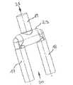
図1は、マニホルドパイプ2を有する管状中空体1を示し、マニホルドパイプ2の端部3,4のそれぞれから分岐パイプ5,6が突出し、さらに管状中空体1は、接続パイプ7を有し、この接続パイプ7は、管状中空体の長さ方向に沿って連結パイプ2から突出する。全体として見ると、管状中空体1は、ほぼY字形のいわゆるフォーク状パイプ8として形成して、分岐パイプ5,6が、マニホルドパイプ2に対して直交する方向に延在する。さらに、接続パイプ7も同様にマニホルドパイプ2に対して直交し、分岐パイプ5,6の2個の遊端は、接続パイプ7の遊端の向きと反対方向に指向する。このようなフォーク状パイプ8によれば、例えば、飲料水を供給する際などの液体分配課題を解決することができる。例えば、接続パイプ7を介して飲料水を導入する場合、飲料水がマニホルドパイプ2に流入し、分岐パイプ5,6間で分配される。 FIG. 1 shows a tubular
このような管状中空体1を製造するために、図2〜図5に示す以下の手順を採用する。まず、第1製造ステップでは、図2に示すマニホルドパイプ2を製造する。マニホルドパイプ2は留め置きロスト用のコアパイプ9とし、プラスチック製のパイプとして成形型で製造する。例えば、プラスチック材料としてPPSU(polyphenylsulphone: ポリフェニルスルフォン)を使用する。図2によれば、コアパイプ9はカラー10を有し、このカラー10はドッキング開口11を包囲し、ドッキング開口11は、コアパイプ9のキャビティ12内に開通する。さらに、コアパイプ9の両側端部にそれぞれ接続開口13,14を有し、これら接続開口13,14のいずれも、ほぼU字状のリム15、およびリム15に隣接する同様のU字状のリム16を有し、これら2個のU字状のリムは、互いに90℃の角度を成すように配置するのが好ましい。 In order to manufacture such a tubular
図1に示すように管状中空体1を製造するとき、図2によるコアパイプ9を成形型(図示せず)内に挿入する。この成形型は、2個の可動性非ロストのコアピース17,18および1個の可動非ロストの留め置きでないコア部分19を有する(このことに関しては、図1および図3を参照)。図3によると、2個のコアピース17および18を、成形型に挿入したコアパイプ9に対して、矢印20の方向に導入し、接続開口13,14を、コアピース17,18の前方端部領域で密封状態になるよう閉鎖する。成形型のコア部分19を、矢印21の方向にコアパイプ9に導入し、ドッキング開口11を、コア部分19の前方端部領域で密封状態になるよう閉鎖する。 When the tubular
つぎに、図3に示す構成を収容した成形型を閉鎖する。この閉鎖時にプラスチック材料を成形型キャビティ内に導入し、コアパイプ9、コアピース17,18、およびコア部分19を、プラスチック材料、特にPPSUでカプセル化する。このようにして、中空体1は最終形状となる。成形型キャビティの設計は、図1に示すように、対応する直径、溝、アンダーカット等が、中空体1において別個に所望通り形成されるように行う。射出したプラスチック材料が硬化した後、2個のコアピース17,18を、成形型(図示せず)のキャビティから図1の矢印22および23の方向に引き抜く。同様の操作をコア部分19にも行い、コア部分19は、矢印24の方向に引き抜く。これら全ての手順に続いて、予め形成したパイプ2は埋設したコアパイプ9を表し、また管状中空体1の他の領域は、アピース17,18およびコア部分19をプラスチック材料、特にPPSUでカプセル化することによって製造する。 Next, the mold containing the configuration shown in FIG. 3 is closed. During this closure, plastic material is introduced into the mold cavity and the core pipe 9,
図4には、プラスチック材料によりカプセル化を実施していない時点における、成形型内の構成がどのような状態であるかを再度明確に示す。コアピース17,18のそれぞれを配置して、さらにコア部分19を配置した状態のマニホルドパイプ2を見ることができる。図5は、図4に示す構成の断面図を示すが、プラスチック材料によるカプセル化を既に実施しているので、分岐パイプ5,6と共に接続パイプ7も既に形成されている。コアピース17,18およびコア部分19は、依然として導入したままの状態にあり、すなわち、依然として除去していない。 FIG. 4 clearly shows again the state of the structure in the mold when the encapsulation is not performed with the plastic material. The manifold pipe 2 can be seen in a state in which the
Claims (4)
Translated fromJapanese両側の端部それぞれに接続開口(13,14)を有し、また前記管状中空体の長さ方向に沿う少なくとも1個のドッキング開口(11)を有する留め置きロスト用のコアパイプ(9)を製造するステップと、
前記コアパイプ(9)を成形型のキャビティ内に導入するコアパイプ導入ステップであって、2個の留め置きでない非ロストのコアピース(17,18)を、前記コアパイプ(9)の端部(3,4)における前記接続開口(13,14)に対してそれぞれ密封状態となるよう配置し、また留め置きでない非ロストのコア部分(19)の一方の端部を前記ドッキング口(11)に対して密封状態となるよう配置した状態で導入する、該コアパイプ導入ステップと、
前記コアパイプ(9)、前記コアピース(17,18)および前記コア部分(19)を導入した後、前記成形型を閉鎖するステップと、
続いて、プラスチック材料(25)を前記成形型のキャビティ内に導入して前記コアパイプ(9)、前記コアピース(17,18)および前記コア部分(19)をカプセル化するステップと、
前記プラスチック材料(25)が硬化した後、前記コアピース(17,18)および前記コア部分(19)を、形成した前記管状中空体(1)から引き抜くステップと、
前記コアピース(17,18)および前記コア部分(19)を引き抜いた後、前記成形型を開くステップとを有することを特徴とする方法。In a method for producing a tubular hollow body having at least three pipe openings and partially or entirely composed of a plastic material,
A core pipe (9) for retaining lost having a connection opening (13, 14) at each end on both sides and having at least one docking opening (11) along the length of the tubular hollow body is manufactured. Steps,
A core pipe introduction step for introducing the core pipe (9) into the cavity of the mold, wherein two non-retained non-lost core pieces (17, 18) are connected to the end (3,4) of the core pipe (9). Are arranged so as to be sealed with respect to the connection openings (13, 14), respectively, and one end of the non-lost core portion (19) which is not retained is sealed with respect to the docking port (11). Introducing the core pipe in a state where it is arranged, and
Closing the mold after introducing the core pipe (9), the core piece (17, 18) and the core portion (19);
Subsequently, encapsulating the core pipe (9), the core piece (17, 18) and the core portion (19) by introducing a plastic material (25) into the cavity of the mold;
Withdrawing the core piece (17, 18) and the core portion (19) from the formed tubular hollow body (1) after the plastic material (25) is cured;
Opening the mold after drawing the core piece (17, 18) and the core part (19).
Applications Claiming Priority (2)
| Application Number | Priority Date | Filing Date | Title |
|---|---|---|---|
| EP09003362AEP2228189B1 (en) | 2009-03-09 | 2009-03-09 | Method for producing a tubular hollow body and tubular hollow body |
| EP09003362.2 | 2009-03-09 |
Publications (2)
| Publication Number | Publication Date |
|---|---|
| JP2010208328A JP2010208328A (en) | 2010-09-24 |
| JP5185307B2true JP5185307B2 (en) | 2013-04-17 |
Family
ID=40933102
Family Applications (1)
| Application Number | Title | Priority Date | Filing Date |
|---|---|---|---|
| JP2010050838AExpired - Fee RelatedJP5185307B2 (en) | 2009-03-09 | 2010-03-08 | Tubular hollow body manufacturing method and tubular hollow body |
Country Status (5)
| Country | Link |
|---|---|
| US (2) | US8652605B2 (en) |
| EP (1) | EP2228189B1 (en) |
| JP (1) | JP5185307B2 (en) |
| CN (1) | CN101830072B (en) |
| ES (1) | ES2399488T3 (en) |
Families Citing this family (7)
| Publication number | Priority date | Publication date | Assignee | Title |
|---|---|---|---|---|
| WO2011061067A1 (en)* | 2009-11-17 | 2011-05-26 | Basell Poliolefine Italia S.R.L. | Thermoshrinkable films |
| DE102013018458A1 (en)* | 2013-11-02 | 2015-05-07 | Dräger Medical GmbH | Y-piece for ventilation system, Y-branch kit, method and apparatus for making same |
| CN109551728B (en)* | 2017-09-26 | 2020-08-21 | 深圳市美好创亿医疗科技股份有限公司 | Silica gel tube forming die with side opening and forming method |
| CN108481767B (en)* | 2018-03-19 | 2021-03-16 | 航天特种材料及工艺技术研究所 | Mutually-embedded topological pipeline structure and integral forming method |
| CN114347358B (en)* | 2021-12-03 | 2023-09-26 | 广东格林精密部件股份有限公司 | Manufacturing equipment and forming method of hollow plastic part with uniform wall thickness |
| DE102023107979A1 (en)* | 2023-03-29 | 2024-10-02 | Gemü Gebr. Müller Apparatebau Gmbh & Co. Kommanditgesellschaft | Mold core, manufacturing process, valve body and device for producing the valve body |
| DE102023128949A1 (en)* | 2023-10-20 | 2025-04-24 | Oras Oy | Manufacturing process for a sanitary fitting |
Family Cites Families (29)
| Publication number | Priority date | Publication date | Assignee | Title |
|---|---|---|---|---|
| US587902A (en)* | 1897-08-10 | Device for draining | ||
| US2449754A (en)* | 1943-12-20 | 1948-09-21 | Seitz Oskar | Fitting for connecting pipes by welding |
| CH448652A (en) | 1967-05-17 | 1967-12-15 | Schibig Arthur | Protective jacket for pipe insulation |
| US3588920A (en)* | 1969-09-05 | 1971-06-29 | Sigmund A Wesolowski | Surgical vascular prostheses formed of polyester fiber paper |
| FR2079486A5 (en)* | 1970-02-03 | 1971-11-12 | Pont A Mousson | Thermosetting resinous tube joints - with glass fibre reinforcement |
| DE3048223C2 (en)* | 1980-12-20 | 1984-10-31 | Erich Prof.Dr.med. 8520 Erlangen Rügheimer | Connection system for gas lines with interlocking connecting elements for ventilation or anesthesia devices |
| US4467002A (en)* | 1981-12-15 | 1984-08-21 | Raychem Limited | Dimensionally-recoverable article |
| DE3239623A1 (en)* | 1982-10-26 | 1984-04-26 | Metzeler Kautschuk GmbH, 8000 München | METHOD FOR PRODUCING A MOLDED HOSE BRANCHING FROM RUBBER AND HOSE PRODUCED BY THIS METHOD |
| JPS60129225A (en)* | 1983-12-16 | 1985-07-10 | Toyo Kagaku Sangyo Kk | Manufacture of coupler having corrosion-resistant inner and outer faces |
| JPS60190316A (en)* | 1984-03-10 | 1985-09-27 | Kyushu Sekisui Kogyo Kk | Formation of frp coupler by resin injection |
| JPS62224450A (en)* | 1987-03-16 | 1987-10-02 | Nippon Kokan Kk <Nkk> | Method for estimating the temperature of molten steel in the ladle |
| JPS6463117A (en)* | 1987-09-04 | 1989-03-09 | Asahi Chemical Ind | Manufacture of hollow resin manifold |
| JPS6467316A (en)* | 1987-09-08 | 1989-03-14 | Taiho Kogyo Co Ltd | Hollow molded product |
| US4830060A (en)* | 1987-11-20 | 1989-05-16 | Proto Corp. | Specialized pipefitting cover for insulated Y-shaped joint |
| JPH01176526A (en)* | 1988-01-06 | 1989-07-12 | Asahi Chem Ind Co Ltd | Method for manufacturing a resin hollow body having a bent pipe part |
| IT1219120B (en) | 1988-03-18 | 1990-05-03 | Dario Orsini | INJECTION MOLDING PROCEDURE OF POLYMERIC CABLE ITEMS FOR THE CONTAINMENT AND CONVEYMENT OF SEAL OF FLUIDS AND MANUFACTURED OBTAINED WITH THIS PROCEDURE |
| DE68920424T2 (en)* | 1989-02-28 | 1995-09-07 | Asahi Chemical Ind | A process for producing a resin article with a curved hollow part and core applicable in this process. |
| US4992626A (en)* | 1989-10-12 | 1991-02-12 | The United States Of America As Represented By The Secretary Of The Army | Electrical cable for vehicles |
| US5250041A (en)* | 1992-01-16 | 1993-10-05 | Fresenius Usa, Inc. | Tubing administration set for use in peritoneal dialysis |
| GB9225528D0 (en)* | 1992-12-07 | 1993-01-27 | Insituform Group Ltd | Improvements relating to the lining of pipelines and passageways |
| JPH07256696A (en)* | 1994-03-23 | 1995-10-09 | Mitsubishi Chem Corp | Method for producing synthetic resin hollow molded article |
| US5627159A (en)* | 1994-10-27 | 1997-05-06 | Life Technologies, Inc. | Enhancement of lipid cationic transfections in the presence of serum |
| US5942169A (en)* | 1994-11-25 | 1999-08-24 | Mitsubishi Engineering-Plastics Corp, | Optimization of overmolding method for three-dimensional hollow molded article |
| JPH08207080A (en)* | 1994-11-25 | 1996-08-13 | Mitsubishi Eng Plast Kk | Three-dimensional hollow molded article and its coating molding method |
| JPH08142114A (en)* | 1994-11-25 | 1996-06-04 | Mitsubishi Eng Plast Kk | Three-dimensional hollow molded article and its coating molding method |
| US5672159A (en)* | 1996-09-30 | 1997-09-30 | Warrick; Nancy J. | Medical tubing support |
| CN1121932C (en)* | 1997-07-09 | 2003-09-24 | 曼内斯曼Vdo股份公司 | Plastic container and method for making the same |
| US5857715A (en)* | 1997-09-04 | 1999-01-12 | J. Ray Mcdermott, S.A. | Pipeline branch arrangement |
| US6432345B1 (en)* | 1999-12-29 | 2002-08-13 | Truseal Usa, Inc. | Single-step method of manufacturing a silicone tube manifold |
- 2009
- 2009-03-09EPEP09003362Apatent/EP2228189B1/enactiveActive
- 2009-03-09ESES09003362Tpatent/ES2399488T3/enactiveActive
- 2010
- 2010-03-05USUS12/718,727patent/US8652605B2/enactiveActive
- 2010-03-08JPJP2010050838Apatent/JP5185307B2/ennot_activeExpired - Fee Related
- 2010-03-09CNCN201010127422.7Apatent/CN101830072B/ennot_activeExpired - Fee Related
- 2014
- 2014-01-07USUS14/149,344patent/US9724883B2/enactiveActive
Also Published As
| Publication number | Publication date |
|---|---|
| CN101830072A (en) | 2010-09-15 |
| EP2228189B1 (en) | 2012-11-14 |
| US8652605B2 (en) | 2014-02-18 |
| US20100227096A1 (en) | 2010-09-09 |
| CN101830072B (en) | 2015-11-25 |
| US9724883B2 (en) | 2017-08-08 |
| US20140197572A1 (en) | 2014-07-17 |
| JP2010208328A (en) | 2010-09-24 |
| EP2228189A1 (en) | 2010-09-15 |
| ES2399488T3 (en) | 2013-04-01 |
Similar Documents
| Publication | Publication Date | Title |
|---|---|---|
| JP5185307B2 (en) | Tubular hollow body manufacturing method and tubular hollow body | |
| JP5792893B2 (en) | Mold assembly and method for manufacturing a syringe container | |
| CN102454850B (en) | By the end connector of the bellows of co-molded production | |
| CN106457702B (en) | For manufacturing the method and system of multiunit tube joint | |
| JP2013016388A (en) | Connector, and method of manufacturing the same | |
| CN104014732A (en) | Assembled wax mold and production method thereof | |
| JP2019507699A5 (en) | ||
| JP2010076280A (en) | Method for manufacturing branch hose | |
| CN203936323U (en) | A kind of assembly type wax-pattern | |
| JP5697586B2 (en) | Manufacturing method of hollow tube made of synthetic resin | |
| US6565790B2 (en) | Injection-molding an electrical-connector shell | |
| JP6762833B2 (en) | Manufacturing method of tubular resin molded product | |
| JP2008037056A (en) | Method and apparatus for manufacturing vehicular interior trim part | |
| KR20130129340A (en) | Manufacturing method for socket-pipe integrally formed socket | |
| US20100143618A1 (en) | Composite component and a method and device for producing the composite component | |
| JP4360841B2 (en) | U-shaped pipe joint and manufacturing method thereof | |
| US6793863B1 (en) | Process for producing a spark plug boot resistor assembly | |
| FI124158B (en) | Molding unit and method for forming pipe insulating bowl of hardenable insulation material and pipe insulating bowl | |
| TWI701128B (en) | Method for manufacturing curved pneumatic tool casing | |
| ES2896064T3 (en) | Blow molding process | |
| CN209943775U (en) | Secondary forming full plastic three-way joint | |
| CN103715541B (en) | Molded plastic product and the method for manufacturing the molded plastic product | |
| JPH06262636A (en) | Injection molding method | |
| CN100471646C (en) | Method for forming sleeve for pipe joint, sleeve and pipe joint using same | |
| CN101439572A (en) | Molding device of in-mold decoration |
Legal Events
| Date | Code | Title | Description |
|---|---|---|---|
| A977 | Report on retrieval | Free format text:JAPANESE INTERMEDIATE CODE: A971007 Effective date:20110908 | |
| A131 | Notification of reasons for refusal | Free format text:JAPANESE INTERMEDIATE CODE: A131 Effective date:20110913 | |
| A521 | Request for written amendment filed | Free format text:JAPANESE INTERMEDIATE CODE: A523 Effective date:20111213 | |
| A131 | Notification of reasons for refusal | Free format text:JAPANESE INTERMEDIATE CODE: A131 Effective date:20120821 | |
| A521 | Request for written amendment filed | Free format text:JAPANESE INTERMEDIATE CODE: A523 Effective date:20121121 | |
| TRDD | Decision of grant or rejection written | ||
| A01 | Written decision to grant a patent or to grant a registration (utility model) | Free format text:JAPANESE INTERMEDIATE CODE: A01 Effective date:20130108 | |
| A61 | First payment of annual fees (during grant procedure) | Free format text:JAPANESE INTERMEDIATE CODE: A61 Effective date:20130117 | |
| R150 | Certificate of patent or registration of utility model | Ref document number:5185307 Country of ref document:JP Free format text:JAPANESE INTERMEDIATE CODE: R150 Free format text:JAPANESE INTERMEDIATE CODE: R150 | |
| FPAY | Renewal fee payment (event date is renewal date of database) | Free format text:PAYMENT UNTIL: 20160125 Year of fee payment:3 | |
| R250 | Receipt of annual fees | Free format text:JAPANESE INTERMEDIATE CODE: R250 | |
| R250 | Receipt of annual fees | Free format text:JAPANESE INTERMEDIATE CODE: R250 | |
| R250 | Receipt of annual fees | Free format text:JAPANESE INTERMEDIATE CODE: R250 | |
| R250 | Receipt of annual fees | Free format text:JAPANESE INTERMEDIATE CODE: R250 | |
| R250 | Receipt of annual fees | Free format text:JAPANESE INTERMEDIATE CODE: R250 | |
| R250 | Receipt of annual fees | Free format text:JAPANESE INTERMEDIATE CODE: R250 | |
| R250 | Receipt of annual fees | Free format text:JAPANESE INTERMEDIATE CODE: R250 | |
| LAPS | Cancellation because of no payment of annual fees |