JP5184865B2 - Optical connector - Google Patents
Optical connectorDownload PDFInfo
- Publication number
- JP5184865B2 JP5184865B2JP2007292462AJP2007292462AJP5184865B2JP 5184865 B2JP5184865 B2JP 5184865B2JP 2007292462 AJP2007292462 AJP 2007292462AJP 2007292462 AJP2007292462 AJP 2007292462AJP 5184865 B2JP5184865 B2JP 5184865B2
- Authority
- JP
- Japan
- Prior art keywords
- optical connector
- optical
- protective sleeve
- optical fiber
- ferrule
- Prior art date
- Legal status (The legal status is an assumption and is not a legal conclusion. Google has not performed a legal analysis and makes no representation as to the accuracy of the status listed.)
- Active
Links
- 230000003287optical effectEffects0.000titleclaimsdescription282
- 239000013307optical fiberSubstances0.000claimsdescription155
- 230000001681protective effectEffects0.000claimsdescription113
- 239000000835fiberSubstances0.000claimsdescription45
- 230000003014reinforcing effectEffects0.000claimsdescription44
- 238000007526fusion splicingMethods0.000claimsdescription40
- 239000000853adhesiveSubstances0.000claimsdescription21
- 230000001070adhesive effectEffects0.000claimsdescription21
- 230000004927fusionEffects0.000claimsdescription15
- 210000000078clawAnatomy0.000claimsdescription9
- 230000002093peripheral effectEffects0.000claimsdescription6
- 238000000034methodMethods0.000description25
- 239000011248coating agentSubstances0.000description19
- 238000000576coating methodMethods0.000description19
- 238000005452bendingMethods0.000description16
- 230000008878couplingEffects0.000description15
- 238000010168coupling processMethods0.000description15
- 238000005859coupling reactionMethods0.000description15
- 239000000428dustSubstances0.000description6
- 238000010438heat treatmentMethods0.000description6
- 238000005498polishingMethods0.000description6
- 230000008602contractionEffects0.000description5
- 230000006835compressionEffects0.000description4
- 238000007906compressionMethods0.000description4
- 238000001746injection mouldingMethods0.000description4
- 239000011347resinSubstances0.000description4
- 229920005989resinPolymers0.000description4
- 230000004308accommodationEffects0.000description3
- 238000005520cutting processMethods0.000description3
- 238000010586diagramMethods0.000description3
- 230000004048modificationEffects0.000description3
- 238000012986modificationMethods0.000description3
- 230000002787reinforcementEffects0.000description3
- 238000003466weldingMethods0.000description3
- OKTJSMMVPCPJKN-UHFFFAOYSA-NCarbonChemical compound[C]OKTJSMMVPCPJKN-UHFFFAOYSA-N0.000description2
- 229920000271Kevlar®Polymers0.000description2
- 238000010521absorption reactionMethods0.000description2
- 229910052799carbonInorganic materials0.000description2
- 208000028659dischargeDiseases0.000description2
- 239000004761kevlarSubstances0.000description2
- 230000001105regulatory effectEffects0.000description2
- 238000003860storageMethods0.000description2
- 230000000007visual effectEffects0.000description2
- XLYOFNOQVPJJNP-UHFFFAOYSA-NwaterSubstancesOXLYOFNOQVPJJNP-UHFFFAOYSA-N0.000description2
- 229910000831SteelInorganic materials0.000description1
- 230000005540biological transmissionEffects0.000description1
- 238000004140cleaningMethods0.000description1
- 230000006866deteriorationEffects0.000description1
- 238000006073displacement reactionMethods0.000description1
- 230000000694effectsEffects0.000description1
- 239000011521glassSubstances0.000description1
- 239000000155meltSubstances0.000description1
- 238000004904shorteningMethods0.000description1
- 239000007787solidSubstances0.000description1
- 239000010959steelSubstances0.000description1
Images


Classifications
- G—PHYSICS
- G02—OPTICS
- G02B—OPTICAL ELEMENTS, SYSTEMS OR APPARATUS
- G02B6/00—Light guides; Structural details of arrangements comprising light guides and other optical elements, e.g. couplings
- G02B6/24—Coupling light guides
- G02B6/36—Mechanical coupling means
- G02B6/38—Mechanical coupling means having fibre to fibre mating means
- G02B6/3807—Dismountable connectors, i.e. comprising plugs
- G02B6/3833—Details of mounting fibres in ferrules; Assembly methods; Manufacture
- G02B6/3846—Details of mounting fibres in ferrules; Assembly methods; Manufacture with fibre stubs
- G—PHYSICS
- G02—OPTICS
- G02B—OPTICAL ELEMENTS, SYSTEMS OR APPARATUS
- G02B6/00—Light guides; Structural details of arrangements comprising light guides and other optical elements, e.g. couplings
- G02B6/24—Coupling light guides
- G02B6/255—Splicing of light guides, e.g. by fusion or bonding
- G—PHYSICS
- G02—OPTICS
- G02B—OPTICAL ELEMENTS, SYSTEMS OR APPARATUS
- G02B6/00—Light guides; Structural details of arrangements comprising light guides and other optical elements, e.g. couplings
- G02B6/24—Coupling light guides
- G02B6/36—Mechanical coupling means
- G02B6/38—Mechanical coupling means having fibre to fibre mating means
- G02B6/3807—Dismountable connectors, i.e. comprising plugs
- G02B6/3887—Anchoring optical cables to connector housings, e.g. strain relief features
- G02B6/38875—Protection from bending or twisting
- G—PHYSICS
- G02—OPTICS
- G02B—OPTICAL ELEMENTS, SYSTEMS OR APPARATUS
- G02B6/00—Light guides; Structural details of arrangements comprising light guides and other optical elements, e.g. couplings
- G02B6/24—Coupling light guides
- G02B6/36—Mechanical coupling means
- G02B6/38—Mechanical coupling means having fibre to fibre mating means
- G02B6/3807—Dismountable connectors, i.e. comprising plugs
- G02B6/3887—Anchoring optical cables to connector housings, e.g. strain relief features
- G02B6/3888—Protection from over-extension or over-compression
- G—PHYSICS
- G02—OPTICS
- G02B—OPTICAL ELEMENTS, SYSTEMS OR APPARATUS
- G02B6/00—Light guides; Structural details of arrangements comprising light guides and other optical elements, e.g. couplings
- G02B6/24—Coupling light guides
- G02B6/255—Splicing of light guides, e.g. by fusion or bonding
- G02B6/2551—Splicing of light guides, e.g. by fusion or bonding using thermal methods, e.g. fusion welding by arc discharge, laser beam, plasma torch
- G—PHYSICS
- G02—OPTICS
- G02B—OPTICAL ELEMENTS, SYSTEMS OR APPARATUS
- G02B6/00—Light guides; Structural details of arrangements comprising light guides and other optical elements, e.g. couplings
- G02B6/24—Coupling light guides
- G02B6/255—Splicing of light guides, e.g. by fusion or bonding
- G02B6/2558—Reinforcement of splice joint
- G—PHYSICS
- G02—OPTICS
- G02B—OPTICAL ELEMENTS, SYSTEMS OR APPARATUS
- G02B6/00—Light guides; Structural details of arrangements comprising light guides and other optical elements, e.g. couplings
- G02B6/24—Coupling light guides
- G02B6/36—Mechanical coupling means
- G02B6/38—Mechanical coupling means having fibre to fibre mating means
- G02B6/3807—Dismountable connectors, i.e. comprising plugs
- G02B6/3887—Anchoring optical cables to connector housings, e.g. strain relief features
- G02B6/3889—Anchoring optical cables to connector housings, e.g. strain relief features using encapsulation for protection, e.g. adhesive, molding or casting resin
Landscapes
- Physics & Mathematics (AREA)
- General Physics & Mathematics (AREA)
- Optics & Photonics (AREA)
- Engineering & Computer Science (AREA)
- Plasma & Fusion (AREA)
- Mechanical Coupling Of Light Guides (AREA)
Description
Translated fromJapanese本発明は、光コネクタフェルールに予め取り付けられた短尺光ファイバと光ファイバ心線とを融着接続した融着接続部を収容保持する光コネクタに関する。 The present invention relates to an optical connector that accommodates and holds a fusion spliced portion in which a short optical fiber attached in advance to an optical connector ferrule and an optical fiber core wire are fusion-connected.
構内光配線等においては、現地で光ファイバケーブルに光コネクタを取り付ける必要がある。 For on-site optical wiring, etc., it is necessary to attach an optical connector to the optical fiber cable locally.
従来、現地で、光ファイバ心線端に光コネクタフェルールを接続する構造の一形態として、特許文献1(図26)に示す光コネクタがある。
上記特許文献1に示された光コネクタ110は、予め光コネクタフェルール102に取り付けられた短尺光ファイバ103と、現地の光ファイバ心線100とが融着接続により接続され、その融着接続部105の周囲が保護スリーブ101で覆われて補強されている。
そして、コネクタハウジング121は、光コネクタフェルール102から保護スリーブ101の後方の光ファイバ心線100の一部までを内部に収容する構成となっている。
また、コネクタハウジング121は、光コネクタフェルール102の先端を突出させた状態に収容したプラグフレーム122と、光ファイバ心線100の端部を収容したブーツ123と、一端がプラグフレーム122に嵌合・一体化すると共に他端がブーツ123に嵌合・一体化する筒状のストップリング124とを備えている。プラグフレーム122内の光コネクタフェルール102は、圧縮コイルばね125により先端側に付勢されている。この圧縮コイルばね125は、コネクタ接続時に、光コネクタフェルール102の後退を許容し、当該光コネクタフェルール102と相手側光コネクタの光コネクタフェルールとの接触圧を規定範囲に保つ。Conventionally, there is an optical connector shown in Patent Document 1 (FIG. 26) as one form of a structure in which an optical connector ferrule is connected to the end of an optical fiber core wire on site.
In the
The
The
上記した光コネクタ110の、光ファイバ心線端と光コネクタフェルールとの接続は、コネクタハウジングを省略した形態の図28(a)に示すように、現地の光ファイバ心線100の端部を、予め、融着部を保護するための保護スリーブ101に挿通させた状態にしておく。そして、SCコネクタなどのプラグフレームに保持される光コネクタフェルール102に予め取り付けられた短尺光ファイバ103の端部と、光ファイバ心線100の端部とを、それぞれ所定長に渡って被覆を剥いだ状態にして、端部相互を付き合わせて、融着させる。その後、図28(b)に示すように、光ファイバ心線100に装着しておいた保護スリーブ101を融着接続部105の上に移動させ、保護スリーブ101が融着接続部105を覆った補強状態にする。これにより、光コネクタ110は融着接続部105を確実に保護することができる。 The connection between the optical fiber core wire end and the optical connector ferrule of the
ところが、上記の接続において、融着されるそれぞれの光ファイバの端部は、治具で調芯・位置決めする関係で、被覆を剥いだ部位100a,103aの長さを10mm程度に設定する必要があり、また、確実に各光ファイバの被覆部に保護スリーブ101が被さるようにするには、各光ファイバの被覆部と保護スリーブ101との重なりが10mm程度となるように、保護スリーブ101の長さを設定しておく必要があった。 However, in the above connection, the ends of the optical fibers to be fused need to be set to about 10 mm in the lengths of the
即ち、保護スリーブ101の長さは、40mm以上となってしまう。その結果、光コネクタ110は、短尺光ファイバ103の露出した被覆部の長さLと保護スリーブ101の長さ40mmを含んだL+40mm以上と長大化して、十分な収容スペースの確保が難しく、小型のキャビネット等に組み込むことが困難になる場合があった。
なお、光コネクタ110の長大化を阻止するために、保護スリーブ101の長さ寸法を短くすることも考えられるが、この場合、作業者の熟練差又は誤操作等で保護スリーブ101の固定位置が軸方向に位置ずれして、裸の光ファイバが露出してしまう虞があり、各光ファイバ心線の被覆部への重ね代をそれほど短縮することができない。
従って、保護スリーブ101の短縮等には効果が小さく、キャビネット等への収容が難しいという課題は残ったままであった。That is, the length of the
In order to prevent an increase in the length of the
Accordingly, there remains a problem that the effect of shortening the
更に、上記の光コネクタ110の場合は、コネクタ接続時に、相手側の光コネクタフェルールとの当接により光コネクタフェルール102が後退した場合には、光コネクタフェルール102と保護スリーブ101との間の短尺光ファイバ103に圧縮荷重が作用し、この圧縮荷重によって短尺光ファイバ103に曲げが生じ、曲げ損失の増大を招く虞があった。 Further, in the case of the
本発明の目的は、小型のキャビネット等への収容性を高めることができ、しかも、光ファイバの曲げ損失の増加や破損等の問題を回避することのできる光コネクタを提供することである。 An object of the present invention is to provide an optical connector that can improve the accommodation property in a small cabinet or the like and can avoid problems such as an increase in bending loss and breakage of an optical fiber.
上記目的を達成するために、本発明に係る光コネクタは、光コネクタフェルールに取り付けられた短尺光ファイバと光ファイバ心線とを融着接続した融着接続部を収容保持する光コネクタであって、
前記融着接続部に密着して前記融着接続部を補強する保護スリーブの一端が前記光コネクタフェルールに結合されており、前記保護スリーブは熱収縮チューブと該熱収縮チューブに挿通された心棒及び接着チューブとを備え、前記熱収縮チューブが前記光コネクタフェルールに結合され、前記接着チューブは前記融着接続部の周囲における前記熱収縮チューブと前記心棒との間の隙間を埋めていることを特徴とする。To achieve the above object, engagementRu optical connector of the present invention, there in an optical connector for housing and holding a fusion-spliced portion of the short optical fiber fitted to the optical connector ferrule and the optical fiber fusion spliced And
One end of a protective sleeve that is in close contact with the fusion splicing portion and reinforces the fusion splicing portion is coupled to the optical connector ferrule. The protective sleeve includes a heat shrinkable tube and a mandrel inserted through the heat shrinkable tube. An adhesive tube, wherein the heat shrinkable tube is coupled to the optical connector ferrule, and the adhesive tube fills a gap between the heat shrinkable tube and the mandrel around the fusion splicing portion. And
本発明に係る光コネクタにおいて、前記光ファイバ心線は、光コードの端部の外被を所定長除去した状態で前記光コネクタ内に装着され、前記保護スリーブは前記光コネクタフェルールとは結合していない他端側において前記光ファイバ心線の外周を覆っていることが好ましい。In engagingRu optical connector of the present invention, the optical fiber is mounted within the optical connector to be outside of the end portion of the optical fiber cord in a state of a predetermined length is removed, the protective sleeve is coupled to the said optical connector ferrule Itis preferable to cover the outer periphery of the optical fiber core at the other end that is not.
本発明に係る光コネクタにおいて、前記光コネクタフェルールの先端部を突出させると共に、該フェルールを収納するプラグフレームを備えていることが好ましい。In engagingRu optical connector of the present invention, the protruding the distal end portion of said optical connector ferrule, itis preferable to provide a plug frame for accommodating the ferrule.
本発明に係る光コネクタにおいて、前記保護スリーブを内部空間に配置して前記プラグフレームに接続するリアハウジングを備え、該リアハウジングには前記プラグフレームに穿設した係止穴が係合する係止爪が備えられていることが好ましい。In engagingRu optical connector of the present invention, includes a rear housing by positioning the protective sleeve in the internal space communicates with said plug frame, the said rear housing engaging hole bored in the plug frame is engaged engagement Itis preferable that a pawl is provided.
本発明に係る光コネクタにおいて、前記光コードに配された抗張力繊維はリアハウジング後端部にかしめ固定されていることが好ましい。In engagingRu optical connector of the present invention, tensile strength fibers disposed in said optical codeis preferably is caulked to the rear housing rear end.
本発明に係る光コネクタにおいて、前記光コネクタフェルールの先端部を突出させると共に、該フェルールを収納するプラグフレームを備え、該プラグフレームには前記保護スリーブの外周面に突出した位置決め突起をファイバ軸方向に移動可能に案内する案内溝が形成されていることが好ましい。In engagingRu optical connector in this invention, the protruding the tip of the optical connector ferrule, comprising a plug frame for accommodating the ferrule, the fiber axis positioning projection on the plug frame protruding on the outer circumferential surface of the protective sleeve Itis preferable that a guide groove that guides in a direction so as to be movable is formed.
本発明に係る光コネクタにおいて、前記保護スリーブを内部空間に配置して前記プラグフレームに接続すると共に前記光ファイバ心線を保護するブーツを一体に形成したリアハウジングを備え、該リアハウジングには前記プラグフレームに突出形成した係止爪が係合する係止穴が備えられていることが好ましい。In engagingRu optical connector of the present invention, it includes a rear housing which is formed integrally with the boot to protect the optical fiber with by arranging the protective sleeve in the inner space connected to said plug frame and said rear housing Itis preferable that a locking hole that engages with a locking claw protruding from the plug frame is provided.
本発明に係る光コネクタにおいて、前記保護スリーブの他端と前記リアハウジングの内壁端との間に空間が形成されていることが好ましい。In engagingRu optical connector of the present invention, itis preferable thatthe space is formed between the other end and an inner wall end of the rear housing of the protective sleeve.
本発明に係る光コネクタにおいて、前記光ファイバ心線は、光コードの端部の外被を所定長除去した状態で前記光コネクタ内に装着され、前記リアハウジングの後端に光ファイバ心線を覆う補強チューブが連結されていることが好ましい。In engagingRu optical connector of the present invention, the optical fiber is mounted within the optical connector to be outside of the end portion of the optical fiber cord in a state of a predetermined length is removed, the optical fiber to the rear end of the rear housing Itis preferable that the reinforcing tube which covers is connected.
本発明に係る光コネクタにおいて、前記補強チューブは、連結部材を介して前記リアハウジングの後端と連結され、前記連結部材は、前記光コードに配された抗張力繊維をかしめ固定していることが好ましい。In engagingRu optical connector of the present invention, the reinforcing tube is connected to the rear end of the rear housing via a coupling member, the coupling member may have riveted the tensile strength fibers disposed in said optical codeIs preferred .
本発明に係る光コネクタにおいて、前記保護スリーブ内に配置される前記短尺光ファイバ及び前記光ファイバ心線のファイバ位置と、前記光コネクタフェルールの軸中心とが一致していることが好ましい。In engagingRu optical connector of the present invention, and the fiber position of the short optical fiber and the optical fiber is disposed within the protective sleeve, itis preferable that the axial center of said optical connector ferrule match.
本発明の光コネクタによれば、保護スリーブの一端が光コネクタフェルールに結合されるため、作業者の熟練度に関係なく、融着接続部を中央位置に設定する保護スリーブの位置決めが正確になされる。その結果、保護スリーブの端部と光ファイバ心線の被覆部との重なり代を短縮でき、これにより、保護スリーブの長さを大幅に短縮して、光コネクタの長さをコンパクトにすることができる。
従って、光コネクタのコンパクト化により、小型キャビネット等への収容性を高めることができる。
また、融着接続部の周囲を覆う保護スリーブは、光コネクタフェルールに結合されていて、コネクタ接続時に相手側の光コネクタフェルールとの当接により当該光コネクタフェルールが後退した場合に、光コネクタフェルールと一体に保護スリーブも後退するため、短尺光ファイバに大きな圧縮荷重が作用することがない。
従って、コネクタ接続作業の際、光コネクタフェルールに取り付けられた短尺光ファイバに大きな曲げ荷重が作用することを防止して、光ファイバの曲げ損失の増加や破損等の問題を回避することもできる。According to the optical connector of the present invention, since one end of the protective sleeve is coupled to the optical connector ferrule, the protective sleeve is accurately positioned to set the fusion splicing portion at the central position regardless of the skill level of the operator. The As a result, the overlap margin between the end portion of the protective sleeve and the covering portion of the optical fiber core wire can be shortened, thereby significantly reducing the length of the protective sleeve and making the optical connector length compact. it can.
Accordingly, the compactness of the optical connector can increase the capacity to accommodate a small cabinet or the like.
The protective sleeve that covers the periphery of the fusion splicing part is coupled to the optical connector ferrule, and when the optical connector ferrule is retracted due to contact with the other optical connector ferrule when the connector is connected, the optical connector ferrule Since the protective sleeve also moves backward together, a large compressive load does not act on the short optical fiber.
Therefore, during connector connection work, it is possible to prevent a large bending load from acting on the short optical fiber attached to the optical connector ferrule, and to avoid problems such as an increase in the bending loss and breakage of the optical fiber.
また、光ファイバ心線は、たとえ光コードの外被が除去された状態で光コネクタの後方より露出しても、この露出部分が、補強チューブで覆われて補修される。
従って、現地で行なう融着接続作業を良好にするために、光コードの外被を大きく除去して光ファイバ心線が光コネクタより露出されても、補強チューブで覆うことで、光ファイバの曲げ損失の増加等を防止することができる。Further, even if the optical fiber core wire is exposed from the rear side of the optical connector in a state where the jacket of the optical cord is removed, the exposed portion is covered with the reinforcing tube and repaired.
Therefore, in order to improve the fusion splicing work performed locally, even if the optical fiber jacket is largely removed and the optical fiber core wire is exposed from the optical connector, the optical fiber is bent by covering it with a reinforcing tube. An increase in loss can be prevented.
以下、本発明に係る光コネクタの好適な実施の形態について、図面を参照して詳細に説明する。
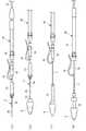
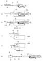
図1は本発明に係る光コネクタの一実施形態の外観斜視図、図2は図1に示した光コネクタの分解斜視図、図3は光コネクタの分解平面図、図4は光コネクタの分解側面図、図5は光コネクタの縦断面図である。DESCRIPTION OF EXEMPLARY EMBODIMENTS Hereinafter, preferred embodiments of an optical connector according to the invention will be described in detail with reference to the drawings.
1 is an external perspective view of an optical connector according to an embodiment of the present invention, FIG. 2 is an exploded perspective view of the optical connector shown in FIG. 1, FIG. 3 is an exploded plan view of the optical connector, and FIG. A side view and FIG. 5 are longitudinal sectional views of the optical connector.
この一実施形態の光コネクタ1は、現地の光コード70の外被72(いずれも図13参照)を所定長除去して露出した光ファイバ心線3の端部に取り付けられるもので、光ファイバ心線3に融着接続する短尺光ファイバ5が予め取り付けられた光コネクタフェルール7と、この光コネクタフェルール7を収容・保持するプラグフレーム9と、光コネクタフェルール7が挿入されるプラグフレーム9の基端側開口に嵌合装着される略円筒状のストッパ11と、光ファイバ心線3と短尺光ファイバ5との融着接続部13(図11参照)の外周を覆って融着接続部13を外装する保護スリーブ15と、保護スリーブ15を配置するための内部空間17を有すると共に先端がプラグフレーム9に結合されてプラグフレーム9に一体化されるリアハウジング18と、短尺光ファイバ5に融着接続される光ファイバ心線3の端部付近を収容して該光ファイバ心線3を保護すると共に先端がリアハウジング18の基端に結合一体化されるブーツ21とを具備している。 The
光コネクタフェルール7は、相手側の光コネクタフェルールに突き合わせ接続される先端軸部7aの後方に、外径が拡径された拡径部7bが装備された形状で、先端軸部7aと中心軸が一致するように、短尺光ファイバ5が取り付けられている。また、光コネクタフェルール7の短尺光ファイバ5が延出される基端側の外周には、図6及び図7に示すように、後述する保護スリーブ15を結合するためのスリーブ結合突起7cが突設されている。 The
光コネクタフェルール7は、プラグフレーム9の基端側開口に挿入されると、図5に示すように、拡径部7bの前端がプラグフレーム9の内周に突設された縮径部9aに当接することで、前方への移動が規制された状態になる。この状態では、図5に示すように、光コネクタフェルール7の先端が所定長L1だけ、プラグフレーム9の先端から突出した状態に位置規制される。 When the
また、図2乃至図5に示すように、プラグフレーム9に位置決めされた光コネクタフェルール7の先端には、保管時等にファイバ端面に塵埃等が付着することを防止するために、ダストキャップ22が被冠装着される。
なお、光コネクタフェルール7の先端面は予め鏡面研磨されていて、現地での研磨加工が不要になされている。Further, as shown in FIGS. 2 to 5, a
In addition, the front end surface of the
光コネクタフェルール7が挿入されたプラグフレーム9内には、フェルール押えばね23が挿入される。このフェルール押えばね23は、プラグフレーム9の基端側開口の内周に嵌合装着されるストッパ11の前端と光コネクタフェルール7の拡径部7bとの間に挟まれて保持される圧縮コイルばねで、光コネクタフェルール7の拡径部7bを上記したプラグフレーム9の縮径部9aに当接させると同時に、後退可能に弾性支持する。 A
プラグフレーム9の基端側開口の内周に嵌合装着されるストッパ11は、その外周に周方向に沿って突設した突起11a(図2参照)を、プラグフレーム9の内壁部に形成された係止溝9b(図5参照)に係合させることで、プラグフレーム9の基端側に固定される。 The
融着接続部13は、図11に示すように、短尺光ファイバ5の端部の被覆5aを剥いだ部分5bと、光ファイバ心線3の端部の被覆3aを剥いだ部分3bとを付き合わせて、付き合わせたファイバ端面同士を融着させることにより形成される。
なお、被覆5aを剥いだ短尺光ファイバ5の端面は、予め、光ファイバに曲げ応力をかけて切断する劈開により、あるいは、研磨によって鏡面加工され、現地での鏡面加工を不要にしている。
また、短尺光ファイバ5の端面は、融着接続前に放電処理してエッジを落としておくと、研磨によって生じるエッジからのチッピングを防ぐことができて好ましい。さらに、短尺光ファイバ5は、被覆を除去した状態で現地まで搬送されるため、傷や吸水による強度低下が抑えられることから、カーボンコートファイバを用いることが好ましい。また、短尺光ファイバ5は、MFDを小さくした曲げに強いファイバであることが好ましい。As shown in FIG. 11, the
The end surface of the short
Moreover, it is preferable that the end face of the short
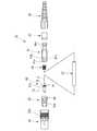
保護スリーブ15は、図7及び図8に示すように、熱収縮チューブ25と、該熱収縮チューブ25に挿通した心棒27及び接着チューブ29と、熱収縮チューブ25の一端に固着される連結部品31とを備え、該連結部品31が光コネクタフェルール7に結合される。 As shown in FIGS. 7 and 8, the
熱収縮チューブ25は、加熱機によって所定温度に加熱すると、熱収縮して、挿通されている心棒27に密着した状態になる。
心棒27は、図8及び図10に示すように、横断面形状が円形状の中実の丸棒で、補強用の心材として、熱収縮チューブ25に挿通されている。心棒27としては、鋼線、ガラスなどを用いることができる。
接着チューブ29は、心棒27に縦添えした形態で熱収縮チューブ25内に挿通された接着剤製のチューブであり、熱収縮チューブ25を熱収縮させる際の加熱で軟化して、熱収縮チューブ25と心棒27との間の隙間34を埋める接着剤となる。When the heat-
As shown in FIGS. 8 and 10, the
The
保護スリーブ15は、当初、図11に示すように熱収縮チューブ25の一端に、心棒27の端部と接着チューブ29の端部とが、所定長L2だけ突出した状態に、熱収縮チューブ25と心棒27と接着チューブ29とを位置決めし、この位置決め状態で図9に示すように熱収縮チューブ25の一端に連結部品31の基端が固定される。
連結部品31は、熱収縮チューブ25及び心棒27の端部が圧入又は接着又は溶着されることにより、これらに固定・一体化されている。As shown in FIG. 11, the
The connecting
連結部品31は、図6に示すように、光コネクタフェルール7側の端部が、光コネクタフェルール7の基端に外嵌する筒部31aになっており、この筒部31aには図9に示すように光コネクタフェルール7のスリーブ結合突起7cが係合する係合穴31bが形成されている。
係合穴31bとスリーブ結合突起7cとを係合することで、保護スリーブ15の一端が光コネクタフェルール7に結合・一体化された状態になる。As shown in FIG. 6, the connecting
By engaging the
以上の保護スリーブ15は、光コネクタ1を組み立てる際には、予め、図2に示したリアハウジング18やブーツ21と共に、光ファイバ心線3を挿通させておき、光ファイバ心線3と短尺光ファイバ5との融着接続後に、融着接続部13の上に戻す。そして、連結部品31を光コネクタフェルール7の基端に結合すると、融着接続部13が丁度保護スリーブ15の長さ方向の略中間位置に位置決めされるように、短尺光ファイバ5及び保護スリーブ15の熱収縮チューブ25,心棒27,接着チューブ29の長さ寸法が設定されている。 When the
更に詳述すると、短尺光ファイバ5と光ファイバ心線3の融着接続後、その融着接続部13を覆うように、保護スリーブ15を融着接続部13上に移動させ、保護スリーブ15の連結部品31を光コネクタフェルール7に結合させた後、熱収縮チューブ25に熱を加えて、融着接続部13の前後の光ファイバ心線3及び短尺光ファイバ5を心棒27に縦添えした状態に固定する。
このように、熱収縮チューブ25を熱収縮させた時、図12に示すように、熱収縮チューブ25の端部が、光ファイバ心線3の被覆3a及び短尺光ファイバ5の被覆5aの上に3mm以上重なるように、各部品の寸法が設定されている。More specifically, after the short
Thus, when the heat-
本実施の形態の場合、図7に示すように、熱収縮チューブ25を熱収縮させた状態では、保護スリーブ15内に配置される短尺光ファイバ5及び光ファイバ心線3のファイバ位置と、光コネクタフェルール7の軸中心とが一致するように、連結部品31及び心棒27等の径寸法等が設定されている。 In the case of the present embodiment, as shown in FIG. 7, in the state where the heat-
図2及び図6に示すように、前述した連結部品31の外周面には、軸方向に沿って延在する位置決め突起31cが設けられている。そして、プラグフレーム9の基端側に固定されるストッパ11には、位置決め突起31cをファイバ軸方向に移動可能に案内する案内溝11cが設けられている。
従って、保護スリーブ15を結合・一体化した光コネクタフェルール7をプラグフレーム9に挿入するとき、位置決め突起31cを案内溝11cの位置に合わせて挿入することで、円滑に、光コネクタフェルール7及び保護スリーブ15を、プラグフレーム9内に装着することができる。As shown in FIGS. 2 and 6, a
Accordingly, when the
リアハウジング18は、保護スリーブ15の周囲を覆う筒状構造体で、樹脂の射出成形等により形成されている。このリアハウジング18の先端は、図3乃至図5に示すように、プラグフレーム9の基端に外嵌する筒部18aになっている。そして、この筒部18aには、プラグフレーム9の基端に外嵌させたときに、プラグフレーム9の基端外周に突出形成されている係止爪9cに係合する係止穴18bが備えられている。
以上のリアハウジング18は、保護スリーブ15の熱収縮処理後に、保護スリーブ15の上に被せられ、先端側の係止穴18bをプラグフレーム9の係止爪9cに係合させることにより、プラグフレーム9に結合されて一体化される。The
The
本実施の形態の場合、リアハウジング18が結合されたプラグフレーム9の外周には、コネクタ接続する際のつまみ部となるSCコネクタつまみ33が被冠装着される。このSCコネクタつまみ33は、光コネクタ1の先端側の外観を提供する外装部材で、外側面には、つかみ易くするための滑り止め用の凹凸33aが形成されている。 In the case of the present embodiment, an
ブーツ21は、リアハウジング18の後方に延出する光ファイバ心線3に急激な曲げが作用しないように、光ファイバ心線3を保護するもので、先端がリアハウジング18の基端に嵌合又は螺着することにより、リアハウジング18に結合一体化される。
但し、樹脂の射出成形により、リアハウジング18と一体形成するようにしても良い。The
However, it may be formed integrally with the
本実施の形態の場合、図5に示すように、保護スリーブ15の他端15aとこの他端15aに対向するブーツ21内の内壁端21aとの間には、保護スリーブ15の後退を許容する空間35が形成されている。 In the case of the present embodiment, as shown in FIG. 5, the
更に、図2及び図5に示すように、ブーツ21の内壁端21aの後方には、光ファイバ心線3に被せられる補強チューブ37が挿入装着される。
補強チューブ37は、先端に拡径した抜け止め部37aが設けられており、抜け止め部37aが引っかかることで、ブーツ21の後方側への移動が規制される。補強チューブ37は適度な弾性を有したチューブで、光ファイバ心線3が急激に曲げられることを防止する。Further, as shown in FIGS. 2 and 5, a reinforcing
The reinforcing
以上に説明した光コネクタ1によれば、保護スリーブ15の一端が光コネクタフェルール7に結合されるため、作業者の熟練度に関係なく、保護スリーブ15の位置決めが正確になる。その結果、保護スリーブ15の端部と光ファイバ心線3の被覆部との重なり代を図12に示したように3mm程度まで短縮でき、これにより、保護スリーブ15の長さを大幅に短縮して、光コネクタ1の長さを短尺光ファイバ5の露出した被覆部の長さLと保護スリーブ15の長さ26mmを含んだL+26mm程度にしてコンパクトにできる。
従って、光コネクタ1のコンパクト化により、小型の架空クロージャ等への収容性を高めることができる。According to the
Therefore, the compactness of the
また、光コネクタフェルール7に予め取り付けられている短尺光ファイバ5や融着接続部13の周囲を覆う保護スリーブ15は、光コネクタフェルール7に結合されていて、コネクタ接続時に相手側の光コネクタフェルールとの当接により当該光コネクタフェルール7が後退した場合には、光コネクタフェルール7と一体に保護スリーブ15も後退するため、短尺光ファイバ5に大きな圧縮荷重が作用することがない。
従って、コネクタ接続作業の際に、光コネクタフェルール7に取り付けられた短尺光ファイバ5に大きな曲げ荷重が作用することを防止して、光ファイバの曲げ損失の増加や破損等の問題を回避することもできる。A
Therefore, a large bending load is prevented from acting on the short
また、本実施の形態の光コネクタ1では、保護スリーブ15は熱収縮チューブ25と該熱収縮チューブ25に挿通した心棒27及び接着チューブ29と熱収縮チューブ25の一端に固着された連結部品31とを備え、該連結部品31が光コネクタフェルール7と結合する構成となっている。
そのため、保護スリーブ15は、光コネクタフェルール7に取り付けられた短尺光ファイバ5と現地の光ファイバ心線3とを融着接続する前に、現地の光ファイバ心線3の端部を挿通させた状態にしておき、短尺光ファイバ5と光ファイバ心線3との融着接続後に、保護スリーブ15を光コネクタフェルール7側に移動させて、保護スリーブ15の一端の連結部品31を光コネクタフェルール7に結合させることで、簡単に保護スリーブ15を光コネクタフェルール7に結合した状態にできる。Further, in the
Therefore, the
そして、保護スリーブ15は、その一端の連結部品31を光コネクタフェルール7に結合した後、その外周囲にある熱収縮チューブ25を加熱機による加熱処理で熱収縮させるという簡単な操作で、短尺光ファイバ5と現地の光ファイバ心線3との融着接続部13を心棒27に縦添えした状態にしっかりと保持することができ、融着接続部13を堅牢に補強することができる。
即ち、作業設備等を整え難い現地でも、簡単且つ確実に、保護スリーブ15により融着接続部13を保護することができる。Then, the
That is, the
また、本実施の形態の光コネクタ1では、連結部品31は、熱収縮チューブ25及び心棒27が圧入又は接着又は溶着により固定された構成となっている。
即ち、光コネクタフェルール7に結合される保護スリーブ15は、融着接続部13に縦添えされる心棒27やこの心棒27に融着接続部13を押え付ける熱収縮チューブ25が、光コネクタフェルール7に結合される連結部品31に固定されているため、連結部品31と心棒27とのつなぎ目で屈曲等が起こることがなく、保護スリーブ15内の光ファイバ及び融着接続部13を、曲げがかかりにくい良好な状態に維持することができる。また、本実施の形態の光コネクタ1では、連結部品31は、熱収縮チューブと心棒を固定する構造としたが、心棒のみを固定して結合しても良い。Moreover, in the
That is, the
また、本実施の形態の光コネクタ1では、光コネクタフェルール7の先端部を突出させると共に、該フェルールを収納保持するプラグフレーム9を備え、該プラグフレーム9には保護スリーブ15の外周面に突出した位置決め突起31cをファイバ軸方向に移動可能に案内する案内溝11cが形成されている。
即ち、一端の連結部品31が光コネクタフェルール7に結合される保護スリーブ15は、その外周に突設された位置決め突起31cが光コネクタフェルール7を収容保持するプラグフレーム9の案内溝11cに係合することで、プラグフレーム9に対して、ファイバ軸方向にのみ移動可能に保持される。
従って、コネクタ接続時に相手側の光コネクタフェルールとの当接により当該光コネクタフェルール7が後退する場合に、光コネクタフェルール7と一体に保護スリーブ15が後退する動作を円滑にすることができる。Further, the
That is, the
Therefore, when the
また、本実施の形態の光コネクタ1では、保護スリーブ15を内部空間17に配置した状態でプラグフレーム9に接続すると共に光ファイバ心線3を保護するブーツ21を一体に形成したリアハウジング18を備え、該リアハウジング18にはプラグフレーム9に突出形成した係止爪9cが係合する係止穴18bが備えられている。
従って、保護スリーブ15の外周囲はリアハウジング18により覆われて保護されるため、架空クロージャ等への収容する際の取り扱いが容易になる。In the
Accordingly, since the outer periphery of the
また、リアハウジング18は、プラグフレーム9寄りの位置に形成された係止穴18bに、プラグフレーム9に装備された係止爪9cを係合させるだけで、プラグフレーム9に接続できるため、現地で簡単に組み立てでき、現地での作業を容易にすることができる。 Further, the
また、本実施の形態の光コネクタ1において、コネクタ接続時に相手側の光コネクタフェルールとの当接により当該光コネクタフェルール7が後退した場合には、光コネクタフェルール7と一体に保護スリーブ15も後退するが、保護スリーブ15の他端とリアハウジング18の内壁端との間には空間35が形成されているため、保護スリーブ15の後退動作が規制されることがなく、コネクタ接続時における光コネクタフェルール7の後退を無理なく受け入れることができる。 Further, in the
次に、本発明に係る光コネクタの他の実施の形態について説明する。
この実施形態の光コネクタは、現地の光コードの端部に取り付けられた際、光コネクタの後方より露出する光ファイバ心線上に被せられて当該光ファイバ心線を保護する補強チューブを備える。なお、補強チューブは先の実施形態でも装備されたが、本実施形態では、その構成および装着方法について具体的に詳述する。
なお、本実施形態において、補強チューブを除く構成は先の実施形態と同じなので、同一部分、部位には同一符号を付して説明を省略するものとする。Next, another embodiment of the optical connector according to the present invention will be described.
The optical connector of this embodiment includes a reinforcing tube that covers an optical fiber core wire exposed from the rear of the optical connector and protects the optical fiber core wire when attached to the end of an on-site optical cord. In addition, although the reinforcement tube was equipped also in previous embodiment, in this embodiment, the structure and mounting method are explained in full detail concretely.
In addition, in this embodiment, since the structure except a reinforcement tube is the same as previous embodiment, the same code | symbol shall be attached | subjected to the same part and site | part, and description shall be abbreviate | omitted.
図13は本発明に係る光コネクタの他の実施形態の縦断面図、図14は図13のB部拡大断面図、図15は光コネクタの組立手順を説明する工程図である。 FIG. 13 is a longitudinal sectional view of another embodiment of the optical connector according to the present invention, FIG. 14 is an enlarged sectional view of part B of FIG. 13, and FIG. 15 is a process diagram for explaining the assembly procedure of the optical connector.
本実施形態に係る光コネクタ1Aは、現地の光コード70の外被72を除去して露出した光ファイバ心線3に光コネクタフェルール7の短尺光ファイバ5を融着接続する際、融着接続時の作業が良好となるように光コード70の端部の外被72を大きく剥ぐと、光コネクタ1Aの後方より光ファイバ心線3が露出することになるので、この露出した光ファイバ心線3の部分に被せられて、当該光ファイバ心線3を保護する補強チューブ42を備える。 The
なお、光コード70は、端部において外被72を剥ぐ(除去する)と、外周囲を抗張力繊維74のケブラー(図14参照)で覆われた光ファイバ心線3が露出する。 Note that when the
補強チューブ42は、ブーツ21を挿通した先端が、連結部材となるかしめリング44によりリアハウジング18の後端に連結されている。詳述すれば、かしめリング44は、図14に示すように、一端に形成した大径部44aと他端に形成した小径部44bとが中間部44cを介して連続した略円筒体とされている。 The front end of the reinforcing
大径部44aは、リアハウジング18の後端外周面上に緩やかに係合する大きさに開口され、外径方向より圧縮かしめすると縮径してリアハウジング18上に固定係合する。そこで、光コード70をかしめリング44の小径部44b側より挿入すると共に、光コード70の外被72を所定長除去して露出した抗張力繊維74をリアハウジング18上に配置した状態で大径部44aを圧縮かしめすると、抗張力繊維74がリアハウジング18とかしめリング44とで挟持された状態となって、リアハウジング18に固定される。 The large-
小径部44bは、当該小径部44bの外周面上でかしめ可能に形成されたリング46を備える。このリング46を外径方向よりかしめることにより、補強チューブ42は端部がかしめリング44の小径部44bとリング46とで挟持された状態とされて固定される。つまり、補強チューブ42は端部にリアハウジング18との連結部材となるかしめリング44を一体的に装備して後述する補強チューブ組立体40を形成する。なお、リング46はかしめられた状態で、ブーツ21の内壁面21a(図5参照)に引っかかって、補強チューブ42のブーツ21の後方側への移動を規制する。このリング46は、先の実施形態での抜け止め部37aに相当する。 The small diameter portion 44b includes a
補強チューブ42は他端側において一部が該補強チューブ42上に配置され、一部が光コード70の外被72上に配置される熱収縮チューブ48によって位置決め固定される。つまり、補強チューブ42は、光コード70の外被72を所定長除去して光コネクタ1Aの後方より露出している光ファイバ心線3の部分を覆う長さに形成され、光コネクタ1Aに結合して位置ずれすることなく光ファイバ心線3を覆うことができる。 The reinforcing
次に補強チューブを装着する際の組立手順について説明する。
先ず、図15(a)に示すように、現地の光コード70の端部に、ブーツ21、かしめリング44を結合した補強チューブ組立体40、リアハウジング18の順番に当該各部を挿入しておく。Next, an assembling procedure when the reinforcing tube is attached will be described.
First, as shown in FIG. 15A, the respective portions are inserted in the order of the
補強チューブ組立体40は、補強チューブ42のブーツ21側端部に熱収縮チューブ48を装着すると共に、リアハウジング18側の端部に連結部材となるかしめリング44を予めかしめ固定したものである。
熱収縮チューブ48は、補強チューブ42の部分のみ加熱収縮させて補強チューブ42に固定されている。かしめリング44の固定は、補強チューブ42の端部にかしめリング44の小径部44bを嵌入させた状態で、小径部44b上をリング46により補強チューブ42を圧縮かしめして達成される。In the reinforcing
The heat shrinkable
リアハウジング18の先端から引き出された光コード70は、図15(b)に示すように、端部の外被72が所定長除去されて、抗張力繊維74及び光ファイバ心線3を露出させている。露出した抗張力繊維74は、図15(c)に示すように、後作業の邪魔とならないよう、補強チューブ42側に折り返される一方、光ファイバ心線3には、保護スリーブ15が挿通される。 As shown in FIG. 15B, the
保護スリーブ15から引き出された光ファイバ心線3は、図15(d)に示すように、被覆3aを除去して裸ファイバの部分3bを露出させた後、さらに当該部分3bを清掃後、所定長に鏡面カットされる。そして、図15(e)に示すように、光ファイバ心線3の被覆3aを剥いだ部分3bとプラグフレーム9に嵌合装着された短尺光ファイバ5の被覆を剥いだ部分5bとを付き合せて、付き合わせたファイバ端面同士を融着接続する。 As shown in FIG. 15 (d), the optical
保護スリーブ15は、図16(f)に示すように、融着接続部を覆うように移動して、光コネクタフェルール7を介してプラグフレーム9に結合される。
次いで、リアハウジング18は、図16(g)に示すように、保護スリーブ15と同様に移動して、保護スリーブ15上に被せた状態で、プラグフレーム9に結合して一体化される。As shown in FIG. 16 (f), the
Next, as shown in FIG. 16 (g), the
引き続き、光コード70の端部から露出した光ファイバ心線3を、補強チューブ42で覆うために、補強チューブ組立体40を移動させてリアハウジング18に結合するが、先ず、図17(h)に示すように、抗張力繊維74をリアハウジング18の後端外周面上に配置した状態で、補強チューブ組立体40を移動した後、抗張力繊維74を連結部材となるかしめリング44の大径部44aでかしめ固定する。これにより、補強チューブ組立体40はリアハウジング18に結合して一体化される。その後、ブーツ21は、図17(i)に示すように、補給チューブ組立体40上を移動してリアハウジング18に装着する。 Subsequently, in order to cover the optical
補強チューブ組立体40はその他端が、図17(j)に示すように、熱収縮チューブ48を加熱収縮して光コード70上に位置決め固定される。
以上の工程を経ることで、補強チューブ組立体40は一端がリアハウジング18とブーツ21とによって位置決めされ、他端が熱収縮チューブ48によって位置決めされる。これにより、補強チューブ組立体40はファイバ軸方向の動きが規制され、光コネクタ1Aの後方より露出した光ファイバ心線3部分での位置ずれが防止される。The other end of the reinforcing
Through the above steps, one end of the reinforcing
最後に、図17(k)に示すように、プラグフレーム9にSCコネクタつまみ33を装着して組み立てが完了する。 Finally, as shown in FIG. 17 (k), the
上記の実施形態によれば、融着接続作業を良好に行なうために、現地の光コードの外被を大きく除去して光ファイバ心線が光コネクタより露出するような場合でも、露出した光ファイバ心線は補強チューブで覆われるため、曲げなどの外力が作用しても、許容値以下の曲げを阻止して光伝送特性の低下を防止することができる。 According to the above embodiment, in order to perform the fusion splicing work satisfactorily, the exposed optical fiber is removed even when the optical fiber core wire is exposed from the optical connector by largely removing the sheath of the local optical cord. Since the core wire is covered with the reinforcing tube, even if an external force such as bending acts, it is possible to prevent bending below an allowable value and prevent deterioration of optical transmission characteristics.
次に、本発明に係る光コネクタの更に他の実施の形態について説明する。
図18は本発明に係る光コネクタの更なる他の実施形態を示す縦断面図である。なお、本実施形態において、上記の実施形態と同一部分、部位には同一符号を付して説明する。
この実施形態の光コネクタは、光コード70を接続するコード型、光ファイバ心線3を接続する心線型の双方に適用することができる。心線型光コネクタは、SCコネクタつまみの形状がやや異なる他はコード型光コネクタと略共通の部品が用いられる。以下の説明では主にコード型光コネクタ(単に「光コネクタ」とも称す)1Bについて説明する。Next, still another embodiment of the optical connector according to the present invention will be described.
FIG. 18 is a longitudinal sectional view showing still another embodiment of the optical connector according to the present invention. In the present embodiment, the same portions and parts as those in the above embodiment will be described with the same reference numerals.
The optical connector of this embodiment can be applied to both a cord type for connecting the
光コネクタ1Bは、相手側光コネクタの結合される先端側(図18の左側)から、SCコネクタつまみ81と、プラグフレーム83と、ファイバ内蔵フェルール(光コネクタフェルール)85と、保護スリーブ87と、フェルール押えばね89と、リアハウジング91と、かしめリング93と、ブーツ95とを主要な部材として有している。つまり、上記実施形態で説明したストッパ11、連結部品31を使用しない構造となっている。 The
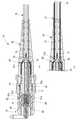
図19は(a)図18に示した光コネクタの縦断面図、(b)補強チューブを装着した変形例の要部縦断面図、図20は(a)光コネクタフェルールの側面図、(b)光コネクタフェルールを短尺光ファイバ側から見た正面図である。
光コネクタフェルール85は、相手側の光コネクタフェルールに突き合わせ接続される先端軸部7aの後方に、外径が拡径された拡径部7bが装備された形状で、先端軸部7aと中心軸が一致するように、短尺光ファイバ5が取り付けられている。また、光コネクタフェルール85の短尺光ファイバ5が延出される基端側の外周には、後述する保護スリーブ87を結合するためのスリーブ結合突起7cが突設されている。19A is a longitudinal cross-sectional view of the optical connector shown in FIG. 18, FIG. 19B is a vertical cross-sectional view of the main part of a modified example equipped with a reinforcing tube, and FIG. 20A is a side view of the optical connector ferrule. FIG. 3 is a front view of the optical connector ferrule as viewed from the short optical fiber side.
The
光コネクタフェルール85は、プラグフレーム83の基端側開口に挿入されると、図19に示すように、拡径部7bの前端がプラグフレーム83の内周に突設された縮径部9aに当接することで、前方への移動が規制された状態になる。この状態では、光コネクタフェルール85の先端が所定長L1だけ、プラグフレーム83の先端から突出した状態に位置規制される。 When the
プラグフレーム83に位置決めされた光コネクタフェルール85の先端には、保管時等にファイバ端面に塵埃等が付着することを防止するために、不図示のダストキャップ(図2中、符号22参照)が被冠装着される。
なお、光コネクタフェルール85の先端面は予め鏡面研磨されていて、現地での研磨加工が不要になされている。A dust cap (not shown) (see
Note that the tip surface of the
光コネクタフェルール85が挿入されたプラグフレーム83内には、フェルール押えばね89が挿入される。このフェルール押えばね89は、後述するプラグフレーム83に係合するリアハウジング91と光コネクタフェルール85の拡径部7bとの間に挟まれて保持される圧縮コイルばねで、光コネクタフェルール85の拡径部7bを上記したプラグフレーム83の縮径部9aに当接させると同時に、後退可能に弾性支持する。 A
図21は(a)図20に示した光コネクタフェルールと該光コネクタフェルールに接続された熱収縮チューブの縦断面図、(b)熱収縮チューブの(a)におけるA−A縦断面図である。
融着接続部13は、短尺光ファイバ5の端部の被覆5aを剥いだ部分5bと、光ファイバ心線3の端部の被覆3aを剥いだ部分3bとを付き合わせて、付き合わせたファイバ端面同士を融着させることにより形成される。
なお、被覆5aを剥いだ短尺光ファイバ5の端面は、予め、光ファイバに曲げ応力をかけて切断する劈開により、あるいは、研磨によって鏡面加工され、現地での鏡面加工を不要にしている。
また、短尺光ファイバ5の端面は、融着接続前に放電処理してエッジを落としておくと、研磨によって生じるエッジからのチッピングを防ぐことができて好ましい。さらに、短尺光ファイバ5は、被覆を除去した状態で現地まで搬送されるため、傷や吸水による強度低下が抑えられることから、カーボンコートファイバを用いることが好ましい。また、短尺光ファイバ5は、MFDを小さくした曲げに強いファイバであることが好ましい。21A is a longitudinal sectional view of the optical connector ferrule shown in FIG. 20 and a heat shrinkable tube connected to the optical connector ferrule, and FIG. 21B is a longitudinal sectional view taken along line AA in FIG. .
The
The end surface of the short
Moreover, it is preferable that the end face of the short
保護スリーブ87は、図21(b)に示すように、熱収縮チューブ25と、該熱収縮チューブ25に挿通した心棒27及び接着チューブ29(図10参照)とを備え、該熱収縮チューブ25が光コネクタフェルール85に結合される。光ファイバ心線3は、光コード70の端部の外被72を所定長除去した状態で光コネクタ1B内に装着され、保護スリーブ87は光コネクタフェルール85とは結合していない他端側において光ファイバ心線3の外周を覆っている。 As shown in FIG. 21B, the
熱収縮チューブ25は、加熱機によって所定温度に加熱すると、熱収縮して、挿通されている心棒27に密着した状態になる。
接着チューブ29は、熱収縮チューブ25を熱収縮させる際の加熱で軟化して、熱収縮チューブ25と心棒27との間の隙間34を埋める接着剤となる。When the heat-
The
保護スリーブ87は、一端に、心棒27の端部と接着チューブ29の端部とが、一致した状態に、熱収縮チューブ25と心棒27と接着チューブ29とを位置決めし、この位置決め状態で光コネクタフェルール85のスリーブ結合突起7cに固定される。
光コネクタフェルール85は、熱収縮チューブ25及び心棒27の端部が圧入又は接着又は溶着されることにより、これらに固定・一体化されている。The
The
保護スリーブ87は、光コネクタフェルール85の基端のスリーブ結合突起7cに結合すると、融着接続部13が丁度保護スリーブ87の長さ方向の略中間位置に位置決めされるように、短尺光ファイバ5及び保護スリーブ87の熱収縮チューブ25,心棒27,接着チューブ29の長さ寸法が設定されている。 When the
保護スリーブ87は、短尺光ファイバ5と光ファイバ心線3の融着接続後、その融着接続部13を覆うように移動させ、光コネクタフェルール85に当接した後、熱収縮チューブ25に加熱を加えて、光ファイバ心線3及び短尺光ファイバ5を心棒27に縦添えした状態に固定する。
このように、熱収縮チューブ25を熱収縮させた時、熱収縮チューブ25の端部が、光ファイバ心線3の被覆3a及びスリーブ結合突起7cの上に2mm以上重なるように、各部品の寸法が設定されている。After the fusion connection between the short
Thus, when the heat-
リアハウジング91は、保護スリーブ87の周囲を覆う筒状構造体で、樹脂の射出成形等により形成されている。このリアハウジング91の先端は、プラグフレーム83の基端に嵌入する筒部91aになっている。そして、この筒部91aには、プラグフレーム83の基端に嵌入したときに、プラグフレーム83の基端外周に穿設されている係止穴83aに係合する係止爪91bが備えられている。
以上のリアハウジング91は、保護スリーブ87の熱収縮処理後に、保護スリーブ87の上に移動して被せられ、先端側の係止爪91bをプラグフレーム83の係止穴83aに係合させることにより、プラグフレーム83に結合されて一体化される。The
The
リアハウジング91が結合されたプラグフレーム83の外周には、コネクタ接続する際のつまみ部となるSCコネクタつまみ81が被冠装着される。このSCコネクタつまみ81は、光コネクタ1Bの先端側の外観を提供する外装部材で、外側面には、つかみ易くするための滑り止め用の凹凸33aが形成されている。 On the outer periphery of the
ブーツ95は、リアハウジング91の後方に延出する光コード70に急激な曲げが作用しないように、光コード70を保護するもので、先端がリアハウジング91の基端に嵌合又は螺着することにより、リアハウジング91に結合一体化される。
但し、樹脂の射出成形により、リアハウジング91と一体形成するようにしても良い。The
However, it may be formed integrally with the
保護スリーブ87の他端87a(図21参照)とこの他端87aに対向するブーツ95内の内壁端との間には、保護スリーブ87の後退を許容する空間35(図19参照)が形成されている。
なお、ブーツ95は、図19(b)に示すように、内壁端の後方に、光コード70に被せられる補強チューブ37が挿入装着される構成であっても良い。
補強チューブ37は、先端に拡径した抜け止め部37aが設けられており、抜け止め部37aがブーツ95内の内壁端に引っかかることで、移動が規制される。補強チューブ37は適度な弾性を有したチューブで光コード70が急激に曲げられることを防止する。A space 35 (see FIG. 19) that allows the
As shown in FIG. 19B, the
The reinforcing
光コネクタフェルール85の拡径部7bの側面には方向合わせマーク97aが設けられる。一方、プラグフレーム83の側壁には方向合わせマーク97bと、視認溝99が設けられている。光コネクタフェルール85は、視認溝99で方向合わせマーク97aを確認しながら方向合わせマーク97bと一致させることで、正規の向きでプラグフレーム83に嵌合されるようになっている。 A
光コネクタ1Bは、現地の光コード70の外被72を除去して露出した光ファイバ心線3に光コネクタフェルール85の短尺光ファイバ5を融着接続する際、融着接続時の作業が良好となるように光コード70の端部の外被72を大きく剥ぐ。光コード70は、端部において外被72を剥ぐ(除去する)と、外周囲を抗張力繊維(ケブラー)74で覆われた光ファイバ心線3が露出する。 In the
抗張力繊維74と外被72は、所定長に切断されて、リアハウジング91の後端部91cに外挿される。外挿された外被72の外周にはかしめリング93が被せられ、かしめリング93は縮径方向にかしめられる。かしめリング93が縮径することにより、外被72と抗張力繊維74はかしめリング93と後端部91cに圧着され、リアハウジング91に固定される。 The
図22は図18に示した光コネクタが心線型に適用された変形例の構成を表す縦断面図である。
上記のように本実施の形態による光コネクタ1Bは、心線型としても用いることができる。この場合、その部品構成は、SCコネクタつまみ81の形状が若干異なる点、抗張力繊維74、外被72を固定するためのかしめリング93が不要となる点のみで他は同一である。なお、図22中、37は光ファイバ心線3用の補強チューブを示す。FIG. 22 is a longitudinal sectional view showing a configuration of a modification in which the optical connector shown in FIG. 18 is applied to a core wire type.
As described above, the
以上に説明した光コネクタ1Bによれば、保護スリーブ87の一端が光コネクタフェルール85に結合されるため、作業者の熟練度に関係なく、保護スリーブ87の位置決めが正確になる。その結果、保護スリーブ87の端部と光ファイバ心線3の被覆部との重なり代を3mm程度まで短縮でき、これにより、保護スリーブ87の長さを大幅に短縮して、光コネクタ1Bの長さをコンパクトにできる。
従って、光コネクタ1Bのコンパクト化により、小型の架空クロージャ等への収容性を高めることができる。According to the
Accordingly, the compactness of the
また、光コネクタフェルール85に予め取り付けられている短尺光ファイバ5や融着接続部13の周囲を覆う保護スリーブ87は、光コネクタフェルール85に結合されていて、コネクタ接続時に相手側の光コネクタフェルールとの当接により当該光コネクタフェルール85が後退した場合には、光コネクタフェルール85と一体に保護スリーブ87も後退するため、短尺光ファイバ5に大きな圧縮荷重が作用することがない。
従って、コネクタ接続作業の際に、光コネクタフェルール85に取り付けられた短尺光ファイバ5に大きな曲げ荷重が作用することを防止して、光ファイバの曲げ損失の増加や破損等の問題を回避することもできる。A
Therefore, a large bending load is prevented from acting on the short
また、本実施の形態の光コネクタ1Bでは、保護スリーブ87は熱収縮チューブ25と該熱収縮チューブ25に挿通した心棒27及び接着チューブ29とを備え、保護スリーブ87が光コネクタフェルール85と結合する構成となっている。 In the
そして、保護スリーブ87は、その一端を光コネクタフェルール85のスリーブ結合突起7cに結合した後、その外周囲にある熱収縮チューブ25を加熱機による加熱処理で熱収縮させるという簡単な操作で、短尺光ファイバ5と現地の光ファイバ心線3との融着接続部13を心棒27に縦添えした状態にしっかりと保持することができ、融着接続部13を堅牢に補強することができる。
即ち、作業設備等を整え難い現地でも、簡単且つ確実に、保護スリーブ87により融着接続部13を保護することができる。The
That is, the
次に、上記の構成を有する光コネクタ1Bの組立手順について説明する。
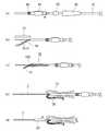
図23(a)〜(e)は図18に示した光コネクタの組立手順を説明する工程図、図24(f)〜(k)は図18に示した光コネクタの組立手順を説明する工程図、図25(l)〜(q)は図18に示した光コネクタの組立手順を説明する工程図である。
光コネクタ1Bを組立てるには、先ず、図23(a)に示すように、現地の光コード70の端部に、ブーツ95、かしめリング93、リアハウジング91、フェルール押えばね89の順番に当該各部を挿入しておく。Next, an assembly procedure of the
23A to 23E are process diagrams for explaining the assembly procedure of the optical connector shown in FIG. 18, and FIGS. 24F to 24K are steps for explaining the assembly procedure of the optical connector shown in FIG. FIGS. 25 (l) to 25 (q) are process diagrams for explaining the assembly procedure of the optical connector shown in FIG.
In order to assemble the
図23(b)に示すように、光コード70の先端側の外被72を除去し、余分な抗張力繊維74はカットする。図23(c)に示すように、外被72に軸線方向の切れ目103を入れて割く。図23(d)に示すように、外被72及び露出した抗張力繊維74は、後作業の邪魔とならないよう折り返す。図23(e)に示すように、光ファイバ心線3に、保護スリーブ87を挿通する。 As shown in FIG. 23B, the
保護スリーブ87から引き出された光ファイバ心線3は、図24(f)に示すように、被覆3aを除去して裸ファイバの部分3bを露出させた後、さらに当該部分3bを清掃する。図24(g)に示すように、保護スリーブ87及び光ファイバ心線3を融着用ファイバホルダ105Aにセットする。図24(h)に示すように所定長に鏡面カットした後、保護スリーブ87及び光ファイバ心線3を不図示の融着機にセットする。 As shown in FIG. 24F, the optical
一方、図24(i)に示すように、短尺光ファイバ5を内蔵した光コネクタフェルール85をフェルールホルダ105Bにセットする。なお、図中22はダストキャップを示す。図24(j)に示すように、光コネクタフェルール85を保持したフェルールホルダ105Bを不図示の融着機にセットする。図24(k)に示すように、融着機にて、光ファイバ心線3の被覆3aを剥いだ部分3bと光コネクタフェルール85の短尺光ファイバ5の被覆を剥いだ部分5bとを付き合せて融着接続する。 On the other hand, as shown in FIG. 24 (i), the
図25(l)に示すように、保護スリーブ87の先端を光コネクタフェルール85のスリーブ結合突起7cに挿入し、融着接続部13を覆い、保護スリーブ87を加熱収縮させる。図25(m)に示すように、折り返していた抗張力繊維74と外被72とを戻す。 As shown in FIG. 25 (l), the tip of the
図25(n)に示すように、光コネクタフェルール85からダストキャップ22を外し、光コネクタフェルール85の先端側からプラグフレーム83を挿入し、フェルール押えばね89を収容しながらリアハウジング91をプラグフレーム83に組み付ける。図25(O)に示すように、抗張力繊維74と外被72とをリアハウジング91の後端部91c上に被せる。 As shown in FIG. 25 (n), the
図25(p)に示すように、かしめリング93を圧着し、抗張力繊維74と外被72とを後端部91cに固定する。最後に、SCコネクタつまみ81とブーツ95とをそれぞれプラグフレーム83とリアハウジング91とに結合して光コネクタ1Bの組立を完成する。 As shown in FIG. 25 (p), the
1、1A、1B 光コネクタ
3 光ファイバ心線
5 短尺光ファイバ
7、85 光コネクタフェルール
7b 拡径部
7c スリーブ結合突起
9、83 プラグフレーム
9a 縮径部
9b 係止溝
11 ストッパ
11a 突起
11c 案内溝
13 融着接続部
15、87 保護スリーブ
17 内部空間
21、95 ブーツ
23、89 フェルール押えばね
25 熱収縮チューブ
27 心棒
29 接着チューブ
31 連結部品
31b 係合穴
31c 位置決め突起
33 SCコネクタつまみ
35 空間
37、42 補強チューブ
38 熱収縮チューブ
40 補強チューブ組立体
44、93 かしめリング
70 光コード
72 抗張力繊維DESCRIPTION OF
Claims (11)
Translated fromJapanese前記融着接続部に密着して前記融着接続部を補強する保護スリーブの一端が前記光コネクタフェルールに結合されており、前記保護スリーブは熱収縮チューブと該熱収縮チューブに挿通された心棒及び接着チューブとを備え、前記熱収縮チューブが前記光コネクタフェルールに結合され、前記接着チューブは前記融着接続部の周囲における前記熱収縮チューブと前記心棒との間の隙間を埋めていることを特徴とする光コネクタ。An optical connector that accommodates and holds a fusion spliced portion in which a short optical fiber attached to an optical connector ferrule and an optical fiber core wire are fusion-connected,
One end of a protective sleeve that is in close contact with the fusion splicing portion and reinforces the fusion splicing portion is coupled to the optical connector ferrule. Theprotective sleeve includes a heat shrinkable tube and a mandrel inserted through the heat shrinkable tube. An adhesive tube, wherein the heat shrinkable tube is coupled to the optical connector ferrule, and the adhesive tube fills a gap between the heat shrinkable tube and the mandrel around the fusion splicing portion. And optical connector.
Priority Applications (1)
| Application Number | Priority Date | Filing Date | Title |
|---|---|---|---|
| JP2007292462AJP5184865B2 (en) | 2006-11-13 | 2007-11-09 | Optical connector |
Applications Claiming Priority (5)
| Application Number | Priority Date | Filing Date | Title |
|---|---|---|---|
| JP2006307138 | 2006-11-13 | ||
| JP2006307138 | 2006-11-13 | ||
| JP2007006251 | 2007-01-15 | ||
| JP2007006251 | 2007-01-15 | ||
| JP2007292462AJP5184865B2 (en) | 2006-11-13 | 2007-11-09 | Optical connector |
Related Child Applications (1)
| Application Number | Title | Priority Date | Filing Date |
|---|---|---|---|
| JP2012213757ADivisionJP5192094B2 (en) | 2006-11-13 | 2012-09-27 | Optical connector |
Publications (2)
| Publication Number | Publication Date |
|---|---|
| JP2008197622A JP2008197622A (en) | 2008-08-28 |
| JP5184865B2true JP5184865B2 (en) | 2013-04-17 |
Family
ID=39401649
Family Applications (2)
| Application Number | Title | Priority Date | Filing Date |
|---|---|---|---|
| JP2007292462AActiveJP5184865B2 (en) | 2006-11-13 | 2007-11-09 | Optical connector |
| JP2012213757AActiveJP5192094B2 (en) | 2006-11-13 | 2012-09-27 | Optical connector |
Family Applications After (1)
| Application Number | Title | Priority Date | Filing Date |
|---|---|---|---|
| JP2012213757AActiveJP5192094B2 (en) | 2006-11-13 | 2012-09-27 | Optical connector |
Country Status (10)
| Country | Link |
|---|---|
| US (1) | US8047726B2 (en) |
| EP (1) | EP2083300B1 (en) |
| JP (2) | JP5184865B2 (en) |
| KR (1) | KR101384076B1 (en) |
| BR (1) | BRPI0718918B1 (en) |
| CA (1) | CA2669715C (en) |
| ES (1) | ES2534898T3 (en) |
| PT (1) | PT2083300E (en) |
| RU (1) | RU2009122464A (en) |
| WO (1) | WO2008059842A1 (en) |
Families Citing this family (47)
| Publication number | Priority date | Publication date | Assignee | Title |
|---|---|---|---|---|
| JP5184865B2 (en)* | 2006-11-13 | 2013-04-17 | 住友電気工業株式会社 | Optical connector |
| JP4630266B2 (en)* | 2006-12-15 | 2011-02-09 | 古河電気工業株式会社 | Optical fiber cord holder, method of manufacturing optical fiber cord with connector using the same, and fusion splicer |
| JP4812652B2 (en)* | 2007-02-19 | 2011-11-09 | 株式会社フジクラ | Optical connector |
| JP4719755B2 (en)* | 2008-02-29 | 2011-07-06 | 住友電気工業株式会社 | Optical connector |
| JP2010039109A (en)* | 2008-08-04 | 2010-02-18 | Fujikura Ltd | Optical connector and assembling method therefor |
| JP5427445B2 (en)* | 2009-03-23 | 2014-02-26 | 株式会社フジクラ | Optical transmission body with connector, optical connector, and optical connector assembly method |
| JP5144623B2 (en)* | 2009-10-28 | 2013-02-13 | Seiオプティフロンティア株式会社 | Optical connector assembly method |
| JP5369053B2 (en)* | 2009-10-28 | 2013-12-18 | Seiオプティフロンティア株式会社 | Optical connector |
| WO2011055877A1 (en)* | 2009-11-06 | 2011-05-12 | 일신테크(주) | Field modular optical connector and assembly method thereof |
| JP5600009B2 (en)* | 2010-01-15 | 2014-10-01 | スリーエム イノベイティブ プロパティズ カンパニー | Optical fiber core support member, optical connector mounting mechanism, optical connector, and optical fiber terminal processing method |
| KR101038195B1 (en)* | 2010-07-08 | 2011-06-01 | 박찬설 | Fiber Optic Connector and How to Assemble It |
| CN103189771B (en)* | 2010-10-29 | 2016-01-20 | Adamant工业株式会社 | Optical fiber connector part and optical fiber connector with the same |
| JP5916996B2 (en) | 2010-12-28 | 2016-05-11 | Seiオプティフロンティア株式会社 | Optical connector and optical connector assembling method |
| WO2012093566A1 (en)* | 2011-01-06 | 2012-07-12 | Seiオプティフロンティア株式会社 | Method for assembling optical connector |
| JP5649000B2 (en)* | 2011-02-02 | 2015-01-07 | 古河電気工業株式会社 | Reinforcing sleeve, reinforcing structure and connecting method for connecting portion of optical fiber core wire |
| CN102289037B (en)* | 2011-08-29 | 2013-01-16 | 深圳市特发信息光网科技股份有限公司 | Field hot-melting quick connector for optical fibers |
| KR101203509B1 (en) | 2011-11-21 | 2012-11-21 | 박찬설 | Fiber optic connectors |
| CN104011572B (en) | 2011-11-23 | 2016-03-16 | Adc电信公司 | Multi-fiber fiber optic connector |
| RU2619816C2 (en) | 2012-02-07 | 2017-05-18 | Тайко Электроникс Райхем Бвба | Cable terminal assembly and method for fixing fiber-optic cable to connector |
| RU2014138122A (en) | 2012-02-20 | 2016-04-10 | Адс Телекоммьюникейшнз, Инк. | FIBER OPTICAL CONNECTOR, FIBER OPTICAL CONNECTOR AND CABLE ASSEMBLY AND METHODS FOR THEIR MANUFACTURE |
| US8939654B2 (en) | 2012-09-27 | 2015-01-27 | Adc Telecommunications, Inc. | Ruggedized multi-fiber fiber optic connector with sealed dust cap |
| KR101535218B1 (en)* | 2013-02-28 | 2015-07-09 | 주식회사 에이제이월드 | Fused optical connector |
| JP2014211512A (en) | 2013-04-18 | 2014-11-13 | 住友電気工業株式会社 | Optical fiber cord |
| JP5937141B2 (en)* | 2013-05-29 | 2016-06-22 | 住友電気工業株式会社 | Method for manufacturing catheter for optical coherence tomography apparatus, and catheter for optical coherence tomography apparatus |
| US9720185B2 (en) | 2014-05-23 | 2017-08-01 | Commscope Technologies Llc | Systems and method for processing optical cable assemblies |
| CN104820265A (en)* | 2015-04-29 | 2015-08-05 | 深圳市特发信息光网科技股份有限公司 | Tail end bending-resistant FC connector |
| BR112018068243A2 (en) | 2016-03-10 | 2019-02-19 | Corning Optical Communications LLC | ferrule-based fiber optic connectors with ferrule retraction balance |
| KR101859917B1 (en)* | 2016-11-22 | 2018-05-23 | 솔텍인포넷 주식회사 | Optical fiber interface adapter |
| JP6873164B2 (en)* | 2017-02-10 | 2021-05-19 | 富士フイルム株式会社 | Manufacturing method of optical connector, photoacoustic generator and optical connector |
| EP3602155A1 (en) | 2017-03-21 | 2020-02-05 | Corning Research & Development Corporation | Fiber optic cable assembly with thermoplastically overcoated fusion splice, and related method and apparatus |
| CN110231684A (en)* | 2018-03-06 | 2019-09-13 | 康普技术有限责任公司 | Modular open air optical fiber connector and its assemble method |
| WO2019173350A1 (en)* | 2018-03-06 | 2019-09-12 | Commscope Technologies Llc | Modular hardened optical fiber connector and assembly method thereof |
| US10976492B2 (en) | 2018-09-07 | 2021-04-13 | Corning Incorporated | Cable with overcoated non-coplanar groups of fusion spliced optical fibers, and fabrication method |
| CN112888978B (en) | 2018-09-07 | 2023-01-13 | 康宁公司 | Optical fiber fanout assembly with ribbonized interface for multi-way fusion splicing and method of making same |
| KR102085172B1 (en)* | 2018-12-07 | 2020-03-04 | 솔텍인포넷 주식회사 | field installable optical connector preventing optical fiber from bending |
| TWM600397U (en)* | 2019-04-11 | 2020-08-21 | 連訊通信股份有限公司 | Optical fiber connector |
| US11360265B2 (en) | 2019-07-31 | 2022-06-14 | Corning Research & Development Corporation | Fiber optic cable assembly with overlapping bundled strength members, and fabrication method and apparatus |
| JP6906069B1 (en)* | 2020-01-09 | 2021-07-21 | 東日本電信電話株式会社 | Transport jig |
| US11886009B2 (en) | 2020-10-01 | 2024-01-30 | Corning Research & Development Corporation | Coating fusion spliced optical fibers and subsequent processing methods thereof |
| US11808983B2 (en) | 2020-11-24 | 2023-11-07 | Corning Research & Development Corporation | Multi-fiber splice protector with compact splice-on furcation housing |
| US11867947B2 (en) | 2021-04-30 | 2024-01-09 | Corning Research & Development Corporation | Cable assembly having routable splice protectors |
| US20230152522A1 (en)* | 2021-11-13 | 2023-05-18 | John Marmo | Re-Spliceable Splice-On Connector |
| US12298561B2 (en)* | 2021-11-13 | 2025-05-13 | John Marmo | Re-spliceable splice-on connector and method of making same |
| US12416766B2 (en) | 2022-11-01 | 2025-09-16 | Panduit Corp. | Fusion spliced connector |
| WO2025053091A1 (en)* | 2023-09-08 | 2025-03-13 | 住友電工オプティフロンティア株式会社 | Optical connector |
| US20250102741A1 (en)* | 2023-09-27 | 2025-03-27 | Ppc Broadband, Inc. | Coupler structurally configured to mechanically couple a fiber cable jacket with a mechanical fiber connector to enhance connection of an optical fiber to the fiber connector |
| WO2025158735A1 (en)* | 2024-01-26 | 2025-07-31 | 住友電工オプティフロンティア株式会社 | Alignment component, assembly component, and method for manufacturing optical connector |
Family Cites Families (18)
| Publication number | Priority date | Publication date | Assignee | Title |
|---|---|---|---|---|
| GB2087585B (en)* | 1980-11-14 | 1984-03-21 | Standard Telephones Cables Ltd | Replacing optical fibre sheathing after fusion splicing |
| CA1202508A (en)* | 1981-05-07 | 1986-04-01 | Norio Murata | Protective packaging assembly and method for optical fibers |
| JPH08160255A (en)* | 1994-12-06 | 1996-06-21 | Nikko Kapura:Kk | Connector for polarization maintaining optical fiber |
| CA2226052A1 (en)* | 1997-02-13 | 1998-08-13 | Diamond Sa | Plug for an optical fiber plug connector and method of its manufacture |
| KR19980078178A (en)* | 1997-04-25 | 1998-11-16 | 윤종용 | Method and device for protecting fusion splicing part of optical fiber |
| US6120193A (en)* | 1997-12-22 | 2000-09-19 | Siecor Corporation | Splice house subassembly and associated connector |
| EP0939327A3 (en)* | 1998-02-27 | 2002-02-13 | Siemens Aktiengesellschaft | Optical fibre connector and method of manufacture thereof |
| DE19933740C2 (en)* | 1999-07-19 | 2003-10-30 | Ccs Technology Inc | Optical fiber connector and method for connection to the end of an optical fiber |
| JP3504567B2 (en)* | 2000-02-23 | 2004-03-08 | 株式会社フジクラ | Optical connector |
| JP2002082257A (en)* | 2000-09-06 | 2002-03-22 | Sumitomo Electric Ind Ltd | Optical connectors and optical connector parts |
| JP2004309841A (en) | 2003-04-08 | 2004-11-04 | Fujikura Ltd | Optical fiber fusion reinforcing member and optical fiber management method using the optical fiber fusion reinforcing member |
| JP2006307138A (en) | 2004-10-26 | 2006-11-09 | Sumitomo Chemical Co Ltd | Ethylene-α-olefin copolymer |
| JP4525488B2 (en) | 2005-06-24 | 2010-08-18 | ソニー株式会社 | Wireless connection system, contactless IC tag, electronic device, program and recording medium |
| US7329049B2 (en)* | 2005-12-27 | 2008-02-12 | Corning Cable Systems Llc | Splice connector for verifying an acceptable splice termination |
| US7264410B1 (en)* | 2006-03-16 | 2007-09-04 | Corning Cable Systems Llc | Dual function splice component for mechanical splice connector |
| JP4690932B2 (en) | 2006-03-30 | 2011-06-01 | 株式会社エクシム | Insulation degradation diagnosis method for power cables |
| JP5184865B2 (en)* | 2006-11-13 | 2013-04-17 | 住友電気工業株式会社 | Optical connector |
| WO2008059843A1 (en)* | 2006-11-13 | 2008-05-22 | Sumitomo Electric Industries, Ltd. | Holder, fusion splicer, and method of assembling optical connector |
- 2007
- 2007-11-09JPJP2007292462Apatent/JP5184865B2/enactiveActive
- 2007-11-13PTPT78317526Tpatent/PT2083300E/enunknown
- 2007-11-13RURU2009122464/28Apatent/RU2009122464A/enunknown
- 2007-11-13USUS11/984,088patent/US8047726B2/enactiveActive
- 2007-11-13CACA2669715Apatent/CA2669715C/enactiveActive
- 2007-11-13ESES07831752.6Tpatent/ES2534898T3/enactiveActive
- 2007-11-13KRKR1020097009821Apatent/KR101384076B1/enactiveActive
- 2007-11-13BRBRPI0718918-4Apatent/BRPI0718918B1/enactiveIP Right Grant
- 2007-11-13EPEP07831752.6Apatent/EP2083300B1/enactiveActive
- 2007-11-13WOPCT/JP2007/072022patent/WO2008059842A1/enactiveApplication Filing
- 2012
- 2012-09-27JPJP2012213757Apatent/JP5192094B2/enactiveActive
Also Published As
| Publication number | Publication date |
|---|---|
| JP5192094B2 (en) | 2013-05-08 |
| WO2008059842A1 (en) | 2008-05-22 |
| BRPI0718918A2 (en) | 2014-05-27 |
| EP2083300A4 (en) | 2012-11-21 |
| JP2012252365A (en) | 2012-12-20 |
| RU2009122464A (en) | 2010-12-20 |
| US20100284653A1 (en) | 2010-11-11 |
| PT2083300E (en) | 2015-06-03 |
| US8047726B2 (en) | 2011-11-01 |
| ES2534898T3 (en) | 2015-04-30 |
| EP2083300A1 (en) | 2009-07-29 |
| BRPI0718918B1 (en) | 2020-07-28 |
| KR101384076B1 (en) | 2014-04-09 |
| EP2083300B1 (en) | 2015-04-01 |
| CA2669715A1 (en) | 2008-05-22 |
| CA2669715C (en) | 2015-12-29 |
| KR20090083373A (en) | 2009-08-03 |
| JP2008197622A (en) | 2008-08-28 |
Similar Documents
| Publication | Publication Date | Title |
|---|---|---|
| JP5184865B2 (en) | Optical connector | |
| JP4719755B2 (en) | Optical connector | |
| JP5277962B2 (en) | Holder, fusion splicer, and optical connector assembling method | |
| CN201152902Y (en) | Optical fiber connector | |
| JP5144623B2 (en) | Optical connector assembly method | |
| JP5916996B2 (en) | Optical connector and optical connector assembling method | |
| JP5290390B2 (en) | Optical connector assembly method | |
| WO2022049792A1 (en) | Optical connector and method of manufacturing optical connector |
Legal Events
| Date | Code | Title | Description |
|---|---|---|---|
| A711 | Notification of change in applicant | Free format text:JAPANESE INTERMEDIATE CODE: A712 Effective date:20100811 | |
| A621 | Written request for application examination | Free format text:JAPANESE INTERMEDIATE CODE: A621 Effective date:20101028 | |
| RD04 | Notification of resignation of power of attorney | Free format text:JAPANESE INTERMEDIATE CODE: A7424 Effective date:20101110 | |
| A977 | Report on retrieval | Free format text:JAPANESE INTERMEDIATE CODE: A971007 Effective date:20110914 | |
| A131 | Notification of reasons for refusal | Free format text:JAPANESE INTERMEDIATE CODE: A131 Effective date:20120306 | |
| A521 | Request for written amendment filed | Free format text:JAPANESE INTERMEDIATE CODE: A523 Effective date:20120427 | |
| RD02 | Notification of acceptance of power of attorney | Free format text:JAPANESE INTERMEDIATE CODE: A7422 Effective date:20120427 | |
| A131 | Notification of reasons for refusal | Free format text:JAPANESE INTERMEDIATE CODE: A131 Effective date:20120731 | |
| A521 | Request for written amendment filed | Free format text:JAPANESE INTERMEDIATE CODE: A523 Effective date:20120927 | |
| A131 | Notification of reasons for refusal | Free format text:JAPANESE INTERMEDIATE CODE: A131 Effective date:20121016 | |
| TRDD | Decision of grant or rejection written | ||
| A01 | Written decision to grant a patent or to grant a registration (utility model) | Free format text:JAPANESE INTERMEDIATE CODE: A01 Effective date:20130108 | |
| A61 | First payment of annual fees (during grant procedure) | Free format text:JAPANESE INTERMEDIATE CODE: A61 Effective date:20130117 | |
| R150 | Certificate of patent or registration of utility model | Ref document number:5184865 Country of ref document:JP Free format text:JAPANESE INTERMEDIATE CODE: R150 Free format text:JAPANESE INTERMEDIATE CODE: R150 | |
| FPAY | Renewal fee payment (event date is renewal date of database) | Free format text:PAYMENT UNTIL: 20160125 Year of fee payment:3 | |
| R250 | Receipt of annual fees | Free format text:JAPANESE INTERMEDIATE CODE: R250 | |
| R250 | Receipt of annual fees | Free format text:JAPANESE INTERMEDIATE CODE: R250 | |
| R250 | Receipt of annual fees | Free format text:JAPANESE INTERMEDIATE CODE: R250 | |
| R250 | Receipt of annual fees | Free format text:JAPANESE INTERMEDIATE CODE: R250 | |
| R250 | Receipt of annual fees | Free format text:JAPANESE INTERMEDIATE CODE: R250 | |
| R250 | Receipt of annual fees | Free format text:JAPANESE INTERMEDIATE CODE: R250 | |
| R250 | Receipt of annual fees | Free format text:JAPANESE INTERMEDIATE CODE: R250 | |
| R250 | Receipt of annual fees | Free format text:JAPANESE INTERMEDIATE CODE: R250 | |
| R250 | Receipt of annual fees | Free format text:JAPANESE INTERMEDIATE CODE: R250 | |
| R250 | Receipt of annual fees | Free format text:JAPANESE INTERMEDIATE CODE: R250 |