JP5182967B2 - Packetized transport stream processing unit - Google Patents
Packetized transport stream processing unitDownload PDFInfo
- Publication number
- JP5182967B2 JP5182967B2JP2011128120AJP2011128120AJP5182967B2JP 5182967 B2JP5182967 B2JP 5182967B2JP 2011128120 AJP2011128120 AJP 2011128120AJP 2011128120 AJP2011128120 AJP 2011128120AJP 5182967 B2JP5182967 B2JP 5182967B2
- Authority
- JP
- Japan
- Prior art keywords
- memory
- data
- packet
- bit
- pointer
- Prior art date
- Legal status (The legal status is an assumption and is not a legal conclusion. Google has not performed a legal analysis and makes no representation as to the accuracy of the status listed.)
- Expired - Lifetime
Links
- 238000012545processingMethods0.000titleclaimsdescription14
- 230000015654memoryEffects0.000description103
- 238000001514detection methodMethods0.000description13
- 238000000034methodMethods0.000description8
- 230000008569processEffects0.000description7
- 230000004044responseEffects0.000description7
- 238000012360testing methodMethods0.000description7
- 238000009825accumulationMethods0.000description5
- 230000001143conditioned effectEffects0.000description5
- 230000002452interceptive effectEffects0.000description5
- 238000007726management methodMethods0.000description5
- 230000003750conditioning effectEffects0.000description4
- 238000010586diagramMethods0.000description4
- 230000006837decompressionEffects0.000description3
- 230000006870functionEffects0.000description3
- 230000008859changeEffects0.000description2
- 238000012937correctionMethods0.000description2
- 230000006399behaviorEffects0.000description1
- 230000005540biological transmissionEffects0.000description1
- 230000003139buffering effectEffects0.000description1
- 238000013479data entryMethods0.000description1
- 238000009795derivationMethods0.000description1
- 239000000284extractSubstances0.000description1
- 238000009432framingMethods0.000description1
- 230000000977initiatory effectEffects0.000description1
- 230000004048modificationEffects0.000description1
- 238000012986modificationMethods0.000description1
- 238000005192partitionMethods0.000description1
- 230000000246remedial effectEffects0.000description1
- 238000005067remediationMethods0.000description1
- 230000008672reprogrammingEffects0.000description1
- 230000003936working memoryEffects0.000description1
Images


Classifications
- H—ELECTRICITY
- H04—ELECTRIC COMMUNICATION TECHNIQUE
- H04N—PICTORIAL COMMUNICATION, e.g. TELEVISION
- H04N7/00—Television systems
- H04N7/16—Analogue secrecy systems; Analogue subscription systems
- H—ELECTRICITY
- H04—ELECTRIC COMMUNICATION TECHNIQUE
- H04N—PICTORIAL COMMUNICATION, e.g. TELEVISION
- H04N21/00—Selective content distribution, e.g. interactive television or video on demand [VOD]
- H04N21/40—Client devices specifically adapted for the reception of or interaction with content, e.g. set-top-box [STB]; Operations thereof
- H04N21/41—Structure of client; Structure of client peripherals
- H04N21/426—Internal components of the client ; Characteristics thereof
- H04N21/42607—Internal components of the client ; Characteristics thereof for processing the incoming bitstream
- H04N21/42623—Internal components of the client ; Characteristics thereof for processing the incoming bitstream involving specific decryption arrangements
- H—ELECTRICITY
- H04—ELECTRIC COMMUNICATION TECHNIQUE
- H04N—PICTORIAL COMMUNICATION, e.g. TELEVISION
- H04N21/00—Selective content distribution, e.g. interactive television or video on demand [VOD]
- H04N21/20—Servers specifically adapted for the distribution of content, e.g. VOD servers; Operations thereof
- H04N21/25—Management operations performed by the server for facilitating the content distribution or administrating data related to end-users or client devices, e.g. end-user or client device authentication, learning user preferences for recommending movies
- H04N21/266—Channel or content management, e.g. generation and management of keys and entitlement messages in a conditional access system, merging a VOD unicast channel into a multicast channel
- H04N21/26606—Channel or content management, e.g. generation and management of keys and entitlement messages in a conditional access system, merging a VOD unicast channel into a multicast channel for generating or managing entitlement messages, e.g. Entitlement Control Message [ECM] or Entitlement Management Message [EMM]
- H—ELECTRICITY
- H04—ELECTRIC COMMUNICATION TECHNIQUE
- H04N—PICTORIAL COMMUNICATION, e.g. TELEVISION
- H04N21/00—Selective content distribution, e.g. interactive television or video on demand [VOD]
- H04N21/40—Client devices specifically adapted for the reception of or interaction with content, e.g. set-top-box [STB]; Operations thereof
- H04N21/41—Structure of client; Structure of client peripherals
- H04N21/418—External card to be used in combination with the client device, e.g. for conditional access
- H04N21/4181—External card to be used in combination with the client device, e.g. for conditional access for conditional access
- H—ELECTRICITY
- H04—ELECTRIC COMMUNICATION TECHNIQUE
- H04N—PICTORIAL COMMUNICATION, e.g. TELEVISION
- H04N21/00—Selective content distribution, e.g. interactive television or video on demand [VOD]
- H04N21/40—Client devices specifically adapted for the reception of or interaction with content, e.g. set-top-box [STB]; Operations thereof
- H04N21/41—Structure of client; Structure of client peripherals
- H04N21/426—Internal components of the client ; Characteristics thereof
- H—ELECTRICITY
- H04—ELECTRIC COMMUNICATION TECHNIQUE
- H04N—PICTORIAL COMMUNICATION, e.g. TELEVISION
- H04N21/00—Selective content distribution, e.g. interactive television or video on demand [VOD]
- H04N21/40—Client devices specifically adapted for the reception of or interaction with content, e.g. set-top-box [STB]; Operations thereof
- H04N21/43—Processing of content or additional data, e.g. demultiplexing additional data from a digital video stream; Elementary client operations, e.g. monitoring of home network or synchronising decoder's clock; Client middleware
- H04N21/44—Processing of video elementary streams, e.g. splicing a video clip retrieved from local storage with an incoming video stream or rendering scenes according to encoded video stream scene graphs
- H04N21/4405—Processing of video elementary streams, e.g. splicing a video clip retrieved from local storage with an incoming video stream or rendering scenes according to encoded video stream scene graphs involving video stream decryption
- H—ELECTRICITY
- H04—ELECTRIC COMMUNICATION TECHNIQUE
- H04N—PICTORIAL COMMUNICATION, e.g. TELEVISION
- H04N21/00—Selective content distribution, e.g. interactive television or video on demand [VOD]
- H04N21/40—Client devices specifically adapted for the reception of or interaction with content, e.g. set-top-box [STB]; Operations thereof
- H04N21/45—Management operations performed by the client for facilitating the reception of or the interaction with the content or administrating data related to the end-user or to the client device itself, e.g. learning user preferences for recommending movies, resolving scheduling conflicts
- H04N21/462—Content or additional data management, e.g. creating a master electronic program guide from data received from the Internet and a Head-end, controlling the complexity of a video stream by scaling the resolution or bit-rate based on the client capabilities
- H04N21/4623—Processing of entitlement messages, e.g. ECM [Entitlement Control Message] or EMM [Entitlement Management Message]
- H—ELECTRICITY
- H04—ELECTRIC COMMUNICATION TECHNIQUE
- H04N—PICTORIAL COMMUNICATION, e.g. TELEVISION
- H04N7/00—Television systems
- H04N7/16—Analogue secrecy systems; Analogue subscription systems
- H04N7/162—Authorising the user terminal, e.g. by paying; Registering the use of a subscription channel, e.g. billing
- H04N7/163—Authorising the user terminal, e.g. by paying; Registering the use of a subscription channel, e.g. billing by receiver means only
- H—ELECTRICITY
- H04—ELECTRIC COMMUNICATION TECHNIQUE
- H04N—PICTORIAL COMMUNICATION, e.g. TELEVISION
- H04N7/00—Television systems
- H04N7/16—Analogue secrecy systems; Analogue subscription systems
- H04N7/162—Authorising the user terminal, e.g. by paying; Registering the use of a subscription channel, e.g. billing
- H04N7/165—Centralised control of user terminal ; Registering at central
- H—ELECTRICITY
- H04—ELECTRIC COMMUNICATION TECHNIQUE
- H04N—PICTORIAL COMMUNICATION, e.g. TELEVISION
- H04N7/00—Television systems
- H04N7/16—Analogue secrecy systems; Analogue subscription systems
- H04N7/167—Systems rendering the television signal unintelligible and subsequently intelligible
- H—ELECTRICITY
- H04—ELECTRIC COMMUNICATION TECHNIQUE
- H04N—PICTORIAL COMMUNICATION, e.g. TELEVISION
- H04N7/00—Television systems
- H04N7/16—Analogue secrecy systems; Analogue subscription systems
- H04N7/167—Systems rendering the television signal unintelligible and subsequently intelligible
- H04N7/1675—Providing digital key or authorisation information for generation or regeneration of the scrambling sequence
Landscapes
- Engineering & Computer Science (AREA)
- Multimedia (AREA)
- Signal Processing (AREA)
- Computer Security & Cryptography (AREA)
- Databases & Information Systems (AREA)
- Two-Way Televisions, Distribution Of Moving Picture Or The Like (AREA)
- Data Exchanges In Wide-Area Networks (AREA)
- Communication Control (AREA)
- Television Systems (AREA)
- Circuits Of Receivers In General (AREA)
- Storage Device Security (AREA)
Description
Translated fromJapanese本発明は、パケット・ビデオ信号からプログラム・コンポーネント・データのパケットを処理するためのシステム、特に、エンタイトルメント(entitlement)情報のために、加入者が条件付きアクセスをするパケット・ペイロード(payload)を検出する回路に関するものである。 The present invention relates to a system for processing a packet of program component data from a packet video signal, in particular, a packet payload for subscribers to conditionally access for entitlement information. The present invention relates to a circuit for detecting
この検出する回路は、例えば、米国特許第5,168,356号および米国特許第5,289,276号から公知であり、エラー保護/訂正の対策(measure)をもたらすそれぞれのパケットと共にパケットで圧縮ビデオ信号を伝送することは有利なことである。前述の特許に開示されたシステムは、それぞれの伝送チャネルから、複数のプログラム・コンポーネントを持つとはいえ単一のテレビジョン・プログラムを伝送し、処理する。これらのシステムは、再生のためにビデオ・コンポーネントを条件付けるようにさらに処理するために、それぞれのプログラムのビデオ信号・コンポーネントを抽出するように、逆トランスポート(inverse transport)・プロセッサを利用する。 This detection circuit is known, for example, from US Pat. No. 5,168,356 and US Pat. No. 5,289,276 and is compressed in packets with each packet providing a measure of error protection / correction. It is advantageous to transmit a video signal. The systems disclosed in the aforementioned patents transmit and process a single television program from each transmission channel, albeit with multiple program components. These systems utilize an inverse transport processor to extract the video signal components of each program for further processing to condition the video components for playback.
それは、例えば、伝送されたテレビジョン信号の受け取りは、信号を暗号化することによって特定の加入者に限定されるという、英国のウイルトシヤー州、クリックレード、ピッツフィールド17(Wilts,Cricklade,17 Pittfield)のスフィスト・テレビジョン出版物(Swift Television Publications)、サテライト・ブック(SATELLITE BOOK)、「衛星テレビ理論と実践の完全ガイド(A COMPLETE GUIDE TO SATELLITE TV THEORY AND PRACTICE)」から公知である。この限定は、異なるエンタイトルメント・データ(entitlement data)を周期的に伝送することによって、放送局の意向で変えることができる。このエンタイトルメント・データは、それぞれの受信機の中にあるスマート・カードによって処理され、関連プログラム・マテリアルを再生する権利が与えられたこれらの受信機内だけの暗号化デバイス又は解読デバイスによる使用のために、暗号キー又は解読キーを生成する。前述のタイプのパケット・ビデオ・システムでは、エンタイトルメント・データは、スマート・カード回路が容易にアクセス可能なデータを含む特定のパケット内に含まれる。 For example, the reception of transmitted television signals is limited to certain subscribers by encrypting the signal, Wiltshire, Cricklade, Pittsfield 17 (Wilts, Cricklade, 17 Pittfield) Swift Television Publications, Satellite Book, "A COMPLETE GUIDE TO SATELLITE TV THEORY AND PRACTICE". This limitation can be changed at the broadcaster's intent by periodically transmitting different entitlement data. This entitlement data is processed by the smart card in each receiver and is used by encryption or decryption devices only within those receivers that are entitled to play the associated program material. For this purpose, an encryption key or a decryption key is generated. In the aforementioned types of packet video systems, entitlement data is contained within specific packets that contain data that is easily accessible by the smart card circuitry.
北アメリカ向けのダイレクト放送衛星システムのような広域放送システムは、多数の加入者(受信契約者)を有する。この数は、非常に大きいため、特定の受信者のエンタイトルメント・データを急に変えることを不可能である。例えば、放送局は、スポーツ試合の切符が売り切れていない場合、スポーツ・スタジアムがあるエリアのテレビ放送を停止しなければならないとする。この情報は、試合の直前まで入手できないかもしれない。もちろん、放送局は、ローカル区域のテレビ放送を停止することの決定を行う直前まで待つことを望む。 A wide area broadcasting system such as a direct broadcasting satellite system for North America has a large number of subscribers (reception contractors). This number is so large that it is impossible to suddenly change the entitlement data for a particular recipient. For example, suppose a broadcaster must stop television broadcasting in an area where a sports stadium is located if a ticket for a sports game is not sold out. This information may not be available until just before the match. Of course, the broadcaster wants to wait until just before making a decision to stop television broadcasting in the local area.
そこで、本発明は、エンタイトルメント・データが直ちにプログラム・マテリアルを受信するための権利を否定するように階層化(layered)されたシステムを提供することを目的とする。 Therefore, the present invention aims to provide a system in which entitlement data is layered so as to deny the right to receive program material immediately.
本発明は、階層化されたエンタイトルメント・データ(layered entitlement data)の送受信のためのシステム/方法である。受信機の実施例は、条件付きアクセス・ペイロード・ヘッダと、残りのエンタイトルメント・データのペイロードとを含むペイロードを有するパケットを選択するパケット・トランスポート・プロセッサを含む。それぞれのペイロード・ヘッダは、各受信機に対してエンタイトルメント・データを処理することを許可又は許可しないように符号化されている、バイトのグループを含んでいる。加入者の特定の条件付きアクセス・コード・ワードで予めプログラム化された条件付きアクセス・フィルタ(conditional access filter)は、加入者の特定(固有)の条件付きアクセス・コード・ワードと照合するために条件付きアクセス・ヘッダのそれぞれのバイトのグルーピングを検査する。一致が生じる場合だけ、プロセッサはエンタイトルメント・データを処理することが許可される。 The present invention is a system / method for sending and receiving layered entitlement data. The receiver embodiment includes a packet transport processor that selects a packet having a payload that includes a conditional access payload header and a payload of the remaining entitlement data. Each payload header contains a group of bytes that are encoded to allow or not allow each receiver to process the entitlement data. A conditional access filter pre-programmed with a subscriber specific conditional access code word is used to match the subscriber specific (unique) conditional access code word Check the grouping of each byte in the conditional access header. Only if a match occurs, the processor is allowed to process the entitlement data.
図1は、複数の異なるテレビジョンまたはインタアクティブ・テレビジョン・プログラムのコンポーネントを含む信号パケットを表す一連のボックスからなる、パケット信号ストリームを示している。これらのプログラム・コンポーネントは圧縮データで形成されていると仮定され、それぞれの画像のビデオ量は可変である。パケットは一定長である。同じ添字を有する文字のパケットは単一プログラムのコンポーネントを表している。例えば、Vi、Ai、Diは、ビデオ、オーディオおよびデータ・パケットを表し、V1、A1、D1と呼ばれているパケットは、プログラム1のためのビデオ、オーディオおよびデータ・コンポーネントを表し、V3、A31、A32、D3は、プログラム3のビデオ、オーディオ1、オーディオ2およびデータ・コンポーネントを表している。データ・パケット(data packets)Diは、例えば、受信機内の所定の動作を開始するための制御データを含むことができる。あるいは、それらは、例えば、受信機内に置かれまたは受信機に関連したマイクロプロセッサによって実行されるアプリケーションを形成する実行可能なコードを含むことができる。 FIG. 1 shows a packet signal stream consisting of a series of boxes representing signal packets containing components of a plurality of different televisions or interactive television programs. These program components are assumed to be formed of compressed data, and the video amount of each image is variable. The packet is a fixed length. A packet of characters having the same subscript represents a single program component. For example, Vi, Ai, Di represent video, audio and data packets, and packets referred to as V1, A1, D1 represent video, audio and data components for
パケットのストリングの上部の行では、特定のプログラムのそれぞれのコンポーネントが一緒にグループ化して示されている。しかしながら、パケットの全ストリングにより示されているように、同一のプログラムからのパケットはグループ化する必要性がない。それぞれのコンポーネントの発生のシーケンスに対するいかなる特定の順序もまたない。 The top line of the packet string shows each component of a particular program grouped together. However, as indicated by the full string of packets, packets from the same program need not be grouped. There is also no specific order for the sequence of occurrence of each component.
それぞれのパケットは、図2に示されるようなプレフィックスおよびペイロードを含むように配置されている。本例のプレフィックスは、4つ(P,BB,CF,CS)が1ビットフィールドで、1つ(SCID)が12ビットフィールドである5つのフィールドを含む、2つの8ビット・バイトを含む。SCIDフィールドは信号コンポーネント識別子(signal component identifier)である。フィールドCFは、パケットのペイロードが暗号化されるかどうかを指示するためのフラグを含み、フィールドCSは、選択可能な2つの暗号解読キーのどれが暗号化パケットを暗号解読するために利用されるべきかを示すフラグを含んでいる。あらゆるパケットのプレフィックスはパケット整列され、したがってそれぞれのフィールドのロケーションは容易に識別できる。 Each packet is arranged to include a prefix and a payload as shown in FIG. The prefix in this example includes two 8-bit bytes, including five fields where four (P, BB, CF, CS) are 1-bit fields and one (SCID) is a 12-bit field. The SCID field is a signal component identifier. The field CF contains a flag to indicate whether the packet payload is encrypted, and the field CS is used to decrypt the encrypted packet, which of the two selectable decryption keys can be selected. Contains a flag indicating what should be done. Every packet prefix is packet aligned, so the location of each field can be easily identified.
それぞれのペイロードの中には、プログラム・コンポーネントに特有である連続計数(continuity count)CC(モジュロ16)、およびTOGGLEフラグビットを含むヘッダがある。連続計数は、単に、同一プログラム・コンポーネントのシーケンシャル・パケットの連続番号である。TOGGLEフラグビットは、論理値レベルを変えるか、または、MPEG圧縮ビデオ・コンポーネントのうちの画像層開始コードの発生に基づいてトグルする1ビット信号である。 Within each payload is a header that includes a continuity count CC (modulo 16) that is specific to the program component, and a TOGGLE flag bit. The sequence count is simply the sequence number of sequential packets of the same program component. The TOGGLE flag bit is a 1-bit signal that toggles based on the occurrence of an image layer start code in the MPEG compressed video component, either changing the logic value level.
図3は、逆トランスポート(inverse transport)・プロセッサの要素を含むディジタル・テレビジョン信号受信機の一部をブロック形式で示している。信号は、アンテナ10によって検出され、受信信号の特定の帯域を抽出し、2進形式のベースバンド圧縮信号を供給するチューナ検出器11に供給される。周波数帯域は、従来方法によってマイクロプロセッサ19を通してユーザによって選択される。通常、放送ディジタル信号は、例えばリード・ソロモン・フォーワード・誤り訂正(FEC)符号により誤り符号化されている。かくして、ベースバンド信号は、FECデコーダ12に供給される。FECデコーダ12は、受信ビデオを同期化し、図1に示された形式を有する信号パケットの誤り訂正済みストリームを供給する。FEC12は、規則的な間隔で、あるいは、例えばメモリ・コントローラ17の要求に応じてパケットを供給する。どちらの場合も、パケット・フレーミングまたは同期信号がFEC回路から供給される。これは、それぞれのパケット情報がFEC12からの転送される回数を示す。 FIG. 3 shows in block form a portion of a digital television signal receiver that includes elements of an inverse transport processor. The signal is detected by the
検出周波数帯域は、パケット形式の複数の時分割多重化プログラムを含むことができる。有用であるために、単一プログラムからのパケットだけは他の回路要素に送られるべきである。本例では、ユーザはどのパケットを選択したらいいかを知らないものと仮定する。この情報は、プログラム・ガイドに含まれる。プログラム・ガイドは、それ自体、SCIDによってプログラム信号・コンポーネントに関連したデータからなるプログラムであり、例えば、加入者のエンタイトルメントに関連している情報を含むことができる。このプログラム・ガイドは、それぞれのプログラムのオーディオ、ビデオ、データ等のコンポーネントのためのSCIDの各プログラムに対するリストである。プログラム・ガイド(図1のパケットD4)は、固定SCIDに割り当てられる。電力が受信機に供給されると、マイクロプロセッサ19は、プログラム・ガイドに関連したSCIDを、類似したプログラマブルSCIDレジスタ13のバンクの1つにロードするようにプログラムされる。FEC12からの信号のそれぞれの検出パケットのプレフィックス部のSCIDフィールドは、他のSCIDレジスタ14に連続的にロードされる。プログラマブル・レジスタおよび受信SCIDレジスタは、比較器15のそれぞれの入力ポートに結合され、受信SCIDはプログラム・ガイドSCIDと比較される。パケットのためのSCIDがプログラム・ガイドSCIDに一致するならば、比較器15は、マイクロプロセッサによる使用のためにメモリ18内の所定のロケーションにそのパケットを経路選択するようにメモリ・コントローラ17を条件付ける。受信SCIDがプログラム・ガイドSCIDに一致しないならば、対応するパケットは単にダンプされる。 The detection frequency band can include a plurality of time division multiplexing programs in a packet format. To be useful, only packets from a single program should be sent to other circuit elements. In this example, it is assumed that the user does not know which packet to select. This information is included in the program guide. The program guide is itself a program consisting of data related to program signals / components by SCID, and may include, for example, information related to subscriber entitlements. This program guide is a list for each program in the SCID for the audio, video, data, etc. components of each program. The program guide (packet D4 in FIG. 1) is assigned to a fixed SCID. When power is supplied to the receiver, the
コンピュータ・キーボードとして示されているが、従来の遠隔制御装置、または受信機フロントパネル・スイッチであってもよいインターフェース20を介して、マイクロプロセッサは、ユーザからのプログラミング・コマンドを待機する。ユーザは、チャンネル4(アナログテレビシステムの用語)に供給されたプログラムを見る要求を出すことができる。マイクロプロセッサ19は、チャンネル4のプログラム・コンポーネントのそれぞれのSCIDのためにメモリ18にロードされたプログラム・ガイドを走査し、対応するコンポーネント信号処理経路に関連するレジスタ・バンク13のプログラマブル・レジスタの中のそれぞれの他のレジスタにこれらのSCIDをロードするようにプログラムされる。 Although shown as a computer keyboard, the microprocessor waits for programming commands from the user via an
所望のプログラムのためのオーディオ、ビデオ、またはデータプログラムの受信パケットは、最終的に、それぞれのオーディオ・プロセッサ23、ビデオ・プロセッサ22、または補助データ・プロセッサ21、(24)信号プロセッサのそれぞれに経路選択されなければならない。データは、比較的定速度で受信されるが、信号プロセッサは、公称的には、バースト状の入力データを必要とする(例えば、それぞれの伸長形式による)。図3に示した典型的なシステムは、最初に、それぞれのパケットを共通メモリ18内の所定メモリ・ロケーションに経路選択する。その後、それぞれのプロセッサ21〜24はメモリ18からのコンポーネント・パケットを要求する。共通メモリを通してコンポーネントの経路選択をすることによって、所望の信号データ速度バッファリングまたはスロットリングの対策が実現できる。 Received packets of audio, video, or data programs for the desired program are ultimately routed to the
オーディオ・パケット、ビデオ・パケットおよびデータ・パケットは、それぞれの所定のメモリ・ロケーションにロードされ、コンポーネント・データへのバッファ・アクセスに便利な信号プロセッサを使用可能にする。それぞれのコンポーネント・パケットのペイロードは適当なメモリ領域にロードされるように、それぞれのSCID比較器はこれらのメモリ領域に関連している。この関連(association)は、メモリ・コントローラ17において実配線されるか、または、この関連はプログラマブルであってもよい。前者の場合、プログラマブル・レジスタ13の中の特定のレジスタは、常にオーディオ、ビデオおよびデータSCIDにそれぞれ割り当てられる。後者の場合、オーディオ、ビデオおよびデータSCIDはプログラマブル・レジスタ13のいずれかにロードされることができる。そして、それぞれのSCIDがプログラマブル・レジスタにロードされるとき、適当な関連はメモリ・コントローラ17においてプログラムされる。 Audio packets, video packets and data packets are loaded into their respective predetermined memory locations, enabling a convenient signal processor for buffer access to component data. Each SCID comparator is associated with these memory areas so that the payload of each component packet is loaded into the appropriate memory areas. This association may be real wired in the memory controller 17, or this association may be programmable. In the former case, specific registers in the
定常状態では、プログラムSCIDがプログラマブル・レジスタ13に記憶された後、受信信号パケットのSCIDは、プログラマブルSCIDレジスタ内のSCIDの全てと比較される。一致が、記憶されたオーディオ、ビデオ、またはデータSCIDのいずれかとなされるならば、対応するパケット・ペイロードは、オーディオ、ビデオまたはデータ・メモリ領域またはメモリ・ブロックにそれぞれ記憶される。 In steady state, after the program SCID is stored in the
それぞれの信号パケットは、信号暗号解読器16を介してFEC12からメモリ・コントローラ17に結合される。信号ペイロードだけが暗号化され、パケット・ヘッダは、変更されない暗号解読器によって通過される。パケットが暗号解読されるべきか否かは、パケット・プレフィックスのCFフラグによって決定され、いかにパケットが暗号解読されるべきか(2つの代替の暗号解読キーのうちの1つ)はCSフラグによって決定される。それぞれのパケットに対していかなるSCID一致もないならば、暗号解読器は単にいかなるデータの通過も不能にする。 Each signal packet is coupled from the
暗号解読器(decryptor)は、スマート・カード装置31によって提供される暗号解読キー(decryption keys)によってプログラムされる。このスマート・カードは、プログラム・ガイドの特定のパケットに含まれたエンタイトルメント情報に応答して、適当な暗号解読キーを生成する。本例のシステムは、2つのレベルの暗号(encryption)またはプログラム・アクセス、すなわちエンタイトルメント・制御メッセージECMおよびエンタイトルメント・管理メッセージEMMを取り入れる。プログラムエンタイトルメント・制御および管理情報は、プログラム・ガイドを含むパケット・ストリームに含まれる特定のSCIDと共に識別できるパケットで規則的に伝送される。これらのパケットの中に含まれるECM情報は、スマート・カードで使用されて、暗号解読器(decryptor)によって使用される暗号解読キー(decryption keys)を生成する。これらのパケットの中に含まれるEMM情報は、加入者固有のスマート・カードで使用されて、加入者がエンタイトルメントされるプログラム・マテリアルを決定する。これらのパケット内のEMMエンタイトルメント情報は、地理的に特有に、またグループ特有に、あるいは加入者特有にされることができる。例えば、本システムは、スマート・カードから課金情報(billing information)をプログラム・プロバイダ、例えば、衛星放送局に知らせるためのモデム(図示せず)を含む。スマート・カードは、例えば、受信機ロケーションのエリア・コードおよび電話交換局と共にプログラムされることができる。EMMは、スマート・カードで処理されるとき、特定のエリア・コードにおける特定のプログラムの受信の権利があるかまたはこのプログラムの受信を否定するデータを含んでいる。 The decryptor is programmed with the decryption keys provided by the
プログラム・プロバイダは、例えば、見る度に支払う(pay-per-view)プログラムに関する限り、非常に短いリード・タイム(lead time)である加入者に権利を付与する能力を要求する。特定の加入者の識別は、特定のプログラムの放送直前まで不能になることがある。このような短いリード・タイムの場合、加入者に基づいてEMMをプログラムすることができないこともある。他の符号化層は条件付きアクセス・コードを含むことによってエンタイトルメント情報に直ちに加えられ、それぞれのパケット内のEMMおよびECMデータの受信を許可/禁止し、それによって、いくつかのプログラムに対してほぼ瞬間の許可/禁止を可能にする。 Program providers, for example, require the ability to entitle subscribers with very short lead times, as far as pay-per-view programs are concerned. Identification of a particular subscriber may not be possible until just before the broadcast of a particular program. For such short lead times, the EMM may not be programmed based on the subscriber. Other encoding layers are immediately added to the entitlement information by including a conditional access code, allowing / disallowing reception of EMM and ECM data in each packet, thereby allowing some programs to Allows almost instant permission / prohibition.
EMMおよびECMエンタイトルメント・データを含むパケット・ペイロードは、特別に符号化された4つの32ビットのグループに配置された128ビットのペイロード・ヘッダを含んでいる。各グループは条件付きアクセス・コードで符号化され、各条件付きアクセス・コードは異なって符号化されることができる。各加入者は特定の条件付きアクセス・コードに割り当てられる。照合フィルタ(matched filter)、すなわちEコード・デコーダ30は、128ビットヘッダ内の加入者固有のビット・パターンを検出するように構成されている。一致が検出されるならば、デコーダはメモリ・コントローラ17およびスマート・カード31と通信し、エンタイトルメント・ペイロードの残りがスマート・カードに利用されるようにする(メモリ18を介して)。一致が検出されないならば、ペイロードは特定の受信機によって受容されない。照合フィルタ30がプログラマブルされるならば、条件付きアクセス・コードは、周期的に変えることができる。これらのコードはスマート・カードによって周期的に供給されることができる。視聴者のエンタイトルメントに関連したスマート・カードの動作に関するより特定の詳細に関しては、サテライト・ブック(SATELLITE BOOK)、「衛星テレビ理論と実践の完全ガイド(A COMPLETE GUIDE TO SATELLITE TV THEORY AND PRACTICE)」の第25節に述べられている。 The packet payload containing EMM and ECM entitlement data includes a 128-bit payload header arranged in four specially encoded groups of 32 bits. Each group is encoded with a conditional access code, and each conditional access code can be encoded differently. Each subscriber is assigned a specific conditional access code. A matched filter, or
照合フィルタ、すなわちEコード・デコーダは、特定のMPEGビデオ・ヘッダを検出するという第2の機能を実行するように構成されている。これらのヘッダは32ビット開始コードである(そのことがエンタイトルメント・ペイロードのヘッダが32ビット・グループで符号化される理由である)。ビデオ・データが消失されるならば、MPEGビデオ・デコーダは特定のデータ・エントリ・ポイントでビデオ・データの伸長だけを再開始できる。これらのエントリ・ポイントは、MPEG開始コードと一致する。デコーダは、ビデオ・パケットの消失後にメモリへのビデオ・データの流れを禁止し、次のMPEG開始コードがデコーダ30によって検出された後だけメモリへのビデオ・ペイロードの書き込みを再開するように、メモリ・コントローラ17と通信するように構成されている。 A matching filter, or E code decoder, is configured to perform a second function of detecting a particular MPEG video header. These headers are 32-bit start codes (that is why the header of the entitlement payload is encoded in a 32-bit group). If video data is lost, the MPEG video decoder can only restart decompression of the video data at a specific data entry point. These entry points coincide with the MPEG start code. The decoder inhibits the flow of video data to the memory after the loss of the video packet and resumes writing the video payload to the memory only after the next MPEG start code is detected by the
図4は、条件付きアクセス情報またはMPEG開始コードを含むパケットを検出するための典型的な装置(図3のデコーダ30)を示している。デコーダ30がエンタイトルメント・ペイロードまたはMPEG開始コードを検出するように条件付けられるかどうかは、現在受信されているSCIDの機能による。図4では、暗号解読器(decryptor)16から供給されたデータは8ビット・バイトであり、パケット整列されていると仮定される。すなわち、エンタイトルメント・ペイロードの第1バイトまたはMPEG開始コードの第1バイトは、パケット・ペイロードの始め等の特定のバイト位置に正確に位置合わせされている。その理由は、特定のヘッダ又は開始コード・ワードを検出するためであり、ビット/バイト・ストリームにおけるそれらの位置は精密に知られているからである。暗号解読器16からのデータは、比較器254のそれぞれの第1の入力接続部に結合された8ビット並列出力ポートを有する8ビットレジスタ250に供給される。この比較器254は、例えば、アンド・ゲートおよびラッチに結合されたそれぞれの出力接続部を有する8つの2入力型排他的ノア(XNOR)回路のバンクで構成することができる。このラッチは、各バイト間隔でアンド・ゲートの結果をラッチするように構成されているデータラッチであってもよい。 FIG. 4 shows an exemplary apparatus (
32ビットMPEG開始コードは、8ビット・レジスタ・バンク265内に4バイトとして記憶される。条件付きアクセス・コードは16の8ビット・レジスタ・バンク257内に8ビット・バイトとして記憶される。レジスタ・バンク251および265のロードは、マイクロプロセッサ19および/またはスマート・カードによって制御される。開始コード・レジスタ265は、4:1のマルチプレクサ266に結合され、条件付きアクセス・コード・レジスタは16:1のマルチプレクサ257に結合されている。マルチプレクサ257,266の出力ポートは、2:1のマルチプレクサ249に結合されている。マルチプレクサ249のそれぞれの出力接続部は比較器254のそれぞれの対応する第2の入力端子に結合されている。(マルチプレクサ249,257および266の入出力接続部は8ビットバスであることに注目)。レジスタ250のそれぞれの出力接続部に示されたそれぞれの値が対応してマルチプレクサ249のそれぞれの出力接続部に示された出力値と同じであるならば、真の信号は対応するデータバイトのための比較器254によって発生される。 The 32-bit MPEG start code is stored as 4 bytes in the 8-
開始コードを検出するために、マルチプレクサ266は、カウンタ258によって走査され、暗号解読器16からの最初の4つのペイロード・データ・バイトの発生と同期して4つの異なるレジスタ265を比較器にシーケンシャルに結合する。一方、条件付きアクセス・コードを検出するために、マルチプレクサ257は、カウンタ258によって走査され、レジスタ265のうちの異なる一つを比較器254にシーケンシャルに結合する。 To detect the start code, the
比較器の出力は、累算・テスト回路255に供給されている。回路255は、所定数のバイト一致条件のいずれかが発生したかどうかを決定し、発生したならば、検査中の特定ペイロードの残りの部分のエンタイトルメント・データのための書き込みイネーブル信号を発生する。本システムでは、エンタイトルメント・ペイロード・ヘッダは、4つの32ビット条件付きコードに配列された128ビットを含む。異なった加入者の条件付きアクセス・フィルタ30は、128ビットのバイトの異なった組み合わせを探すように構成される。例えば、ある加入者装置は条件付きアクセス・コードのうちの最初の4バイトに一致するように構成することができる。他の加入者装置は、条件付きアクセス・コードの第2番目の4バイトに一致するように構成する、などが可能である。これらの典型的な状況のいずれにおいて、回路255は、適当な4つの連続的なバイトに対する一致が発生されたどうかを決定する。 The output of the comparator is supplied to an accumulation /
加入者固有の条件付きアクセス・コードに対してバンク内の16のレジスタの使用は回路構造を多少簡単にする。各加入者は4バイトの条件付きアクセス・コードを有しているので、このコードを16のレジスタ・セット内に4回ロードすることができる。したがって、送信機では、放送局は、送信される条件付きアクセス・コードのうちの4バイトの4つのグループに対する相対ロケーションにかかわる必要がない。代替装置は、加入者固有の条件付きアクセス・コードを保持するように単一グループの4つのレジスタのみを組み込むことができ、これらのレジスタを128ビットのエンタイトルメント・ペイロード・ヘッダによってモジュロ4を反復して走査することができる。 The use of 16 registers in the bank for subscriber-specific conditional access codes simplifies the circuit structure somewhat. Since each subscriber has a 4-byte conditional access code, this code can be loaded four times into the 16 register set. Thus, at the transmitter, the broadcaster does not need to be involved in relative locations for four groups of four bytes of conditional access code to be transmitted. An alternative device can incorporate only a single group of four registers to hold subscriber-specific conditional access codes, and these registers can be modulo 4 with a 128-bit entitlement payload header. It is possible to scan repeatedly.
このことは、好ましくないことには他のサービスのシステム帯域を制限し、あまりにも多くの時間がかかるだけであるので、あらゆる機能に対する232の可能なエンタイトルメント・コードのそれぞれを送信することは実用的でない。グルーピングがそれぞれの4バイトの条件付きアクセス・コードの中の3バイトで規定されるこの制限は、いくつかの論理値グルーピングにより条件付きアクセス・コードを配列することによって多少解決することができる。このように、グループの全ての加入者は、4バイトの条件付きコードの中の1バイトを無視するためにそれぞれのグループの受信機を条件付けることによってアドレス指定することができる。本例では、各4バイト・アクセス・コードは256の加入者を表す。フィルタ条件付けは、例えば、最初の4バイト位置の全ての0を送信し、この条件を検出するように条件付きアクセス・フィルタを構成することによって行われる。この条件が満たされるならば、条件付きアクセス・フィルタは、それぞれの4バイトのグループの3バイトだけの一致を検出するように電気的に再構成される。 This undesirably limits the system bandwidth of other services and only takes too much time, so sending each of the 232 possible entitlement codes for every function is not Not practical. This limitation, in which the grouping is defined by 3 bytes in each 4-byte conditional access code, can be solved somewhat by arranging the conditional access codes by several logical value groupings. In this way, all subscribers in the group can be addressed by conditioning each group's receivers to ignore one byte in the 4-byte conditional code. In this example, each 4-byte access code represents 256 subscribers. Filter conditioning is performed, for example, by sending all 0s in the first 4 byte position and configuring the conditional access filter to detect this condition. If this condition is met, the conditional access filter is electrically reconfigured to detect a match of only 3 bytes in each 4-byte group.
第3の変更例は、全ての加入者の条件付きアクセスを許可するために提供される。これは、オール0(またはオール1)でエンタイトルメント・ペイロードを符号化することによって行われる。したがって、条件付きアクセス・フィルタは、オール・ゼロ検出器(要素261〜263)も含むように構成される。 A third modification is provided to allow conditional access for all subscribers. This is done by encoding the entitlement payload with all 0s (or all 1s). Thus, the conditional access filter is configured to also include an all-zero detector (elements 261-263).
データのそれぞれの受信バイトのビットは8ビット・オア・ゲート263のそれぞれの端子に結合される。このビットの中のいずれかのビットが論理値1であるならば、オア・ゲート263は論理値1を出力する。オア・ゲート263の出力は、D形ラッチ261のデータ入力端子およびQ出力端子にそれぞれ結合された出力および第2の入力を有する2入力オア・ゲート262の一方の入力に結合されている。D形ラッチは入力データバイトの受信と同期してタイミング回路259によってクロックされる。ラッチがリセットされた後、発生するデータバイトのいずれのいかなるビットも論理値1であるならば、ラッチ261は、次のリセットパルスまでそのQ出力で論理値1を示す。ラッチ261のQ出力は、ラッチが1出力レベルを示すときは常に、0出力レベルを示すインバータに結合されている。このように、その後、128ビット(16バイト)のヘッダがレジスタ250を通過されるならば、インバータの出力はハイで、128ビットは0となる。ラッチは、各新しいペイロードの受信よりも前にリセットされる。エンタイトルメント・ペイロード・ヘッダの通過後、インバータからのハイ出力レベルの検出に応答して、回路255はデータ書き込みイネーブル信号を発生する。 The bit of each received byte of data is coupled to a respective terminal of 8-bit OR
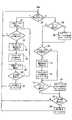
図5は、条件付きアクセス・フィルタ30の動作を示すフローチャートである。この処理は関連したSCIDの検出によって開始される。一旦適当なSCIDが検出されると、ペイロードはフィルタ30に供給される{300}。比較{302}が、ヘッダの最初の4バイトと加入者固有の条件付きアクセス・コードとの間で行われる。一致が生じるならば、エンタイトルメント・データ書き込みイネーブルが発生される{310}。一致が生じないならば、最初の4バイトがオール0に対して検査される{306}。オール0が検出されないならば、ヘッダの第2番目の4バイトは加入者固有の条件付きアクセス・コードと比較される{308}。これらが一致するならば{312}、書き込みイネーブルが発生される{310}。一致しないならば、第3番目の4バイト・セットは加入者固有の条件付きアクセス・コードと比較される{314}。これが一致するならば{316}、書き込みイネーブルが発生される{310}。一致しないならば、第4番目の4バイト・セットが加入者固有の条件付きアクセス・コードと比較される{317}。これらが一致するならば{318}、書き込みイネーブルは発生される{310}。一致しないならば、ヘッダの最後の12バイトが、オール0に対して検査される{320}。オール0が最後の12バイトで検出されるならば、書き込みイネーブルが発生され{310}、検出されないならば、処理は次のパケットを待つ{300}。代替装置では、ステップ{320}で、本システムはヘッダの全16バイトのオール0を探すようにプログラムすることができる。ある種の他の固定パターンが、全て1または例えば、0と1とが交互に現れるパターンのような全て0以外を利用してもよいことを理解すべきである。 FIG. 5 is a flowchart showing the operation of the
ステップ{306}で、最初の4バイトが全て0であるならば、ヘッダの第2番目の4バイトのうちの3つが加入者固有の条件付きアクセス・コードと比較される{354}。図4の装置では、このことは、唯一の4バイトのグループに対する3つの一致を探すように要素255を構成することによって達成される。4バイトのうちの3つが一致するならば{326}、書き込みイネーブルが発生され{322}、一致しないならば、4ヘッダ・バイトのうちの第3のセットのうちの3つが加入者固有の条件付きアクセス・コードと比較される{330}。4バイトのうちの3つが一致するならば{332}、書き込みイネーブル信号が発生され{322}、一致しないならば、最後の4バイトのうちの3つが加入者固有の条件付きアクセス・コードと比較される{336}。これらが一致するならば、書き込みイネーブル信号が発生され{322}、一致しないならばオール0条件が検査される{320}。 In step {306}, if the first 4 bytes are all 0, 3 of the second 4 bytes of the header are compared to the subscriber specific conditional access code {354}. In the apparatus of FIG. 4, this is accomplished by configuring
4バイトのそれぞれのグループのうちの2つだけが一致される場合、他の検出レベルはステップ{324〜340}と同様に組み入れることができることに注目すべきである。このことは、例えば、最初の8バイトを全て0に、または、最初の4バイトを全て1に配列することによって条件付けることができる。この場合、条件付けアクセス・コードによって使用可能にされるそれぞれのグループはずっと大きくなる。 It should be noted that if only two of each group of 4 bytes are matched, other detection levels can be incorporated as well as steps {324-340}. This can be conditioned, for example, by arranging the first 8 bytes to all 0s or the first 4 bytes to all 1. In this case, each group enabled by the conditioning access code is much larger.
メモリにエンタイトルメント・ペイロードを記憶することに関しては、本システムは、条件付きアクセス・コードを受信し、検査するとき、ペイロード・ヘッダをメモリに書き込む。条件付きアクセス・コードが検出されるならば、検出される書き込みイネーブルは、メモリ制御がペイロードの書き込みを継続することを可能にするだけである。反対に、条件付きアクセス・コードがペイロードの最初の16バイトで検出されない場合、ペイロードの残りはメモリに書き込まれなく、条件付きアクセス・ペイロードに対するメモリ・アドレスはペイロード条件付きアクセス・ヘッダの中の16バイトを上書きするためにリセットされる。 With respect to storing the entitlement payload in memory, the system writes a payload header to memory when receiving and examining a conditional access code. If a conditional access code is detected, the detected write enable only allows the memory control to continue writing the payload. Conversely, if a conditional access code is not detected in the first 16 bytes of the payload, the rest of the payload is not written to memory and the memory address for the conditional access payload is 16 in the payload conditional access header. Reset to overwrite bytes.
図6は、1度に32ビット(4バイト)と同じぐらい多数と比較する他の条件付きアクセス・フィルタである。これは、開始コードのバイト位置を予め知らないで開始コードの検出を可能にする。開始コードは、8ビットレジスタに記憶される(8ビットのμPCバスが使用されるために8ビットレジスタが使用される)。レジスタの出力ポートはマルチプレクサ298の第1の入力セットに結合されている。加入者固有の条件付きアクセス・コードは、マルチプレクサ298のための第2の入力セットに結合されたそれぞれの出力ポートを有する第2のレジスタ・バンク299に記憶される。マルチプレクサ298は、比較器270〜273のそれぞれの第1の8ビット入力ポートに接続された出力セットを有する。 FIG. 6 is another conditional access filter that compares as many as 32 bits (4 bytes) at a time. This makes it possible to detect the start code without knowing in advance the byte position of the start code. The start code is stored in an 8-bit register (the 8-bit register is used because the 8-bit μPC bus is used). The output port of the register is coupled to the first input set of
レジスタ265または299が比較器に結合されるかどうかは、μPCに応答する累算・テスト回路297によって制御される。 Whether
暗号解読器16からの入力バイトは並列/直列レジスタ247〜277に結合される。それぞれのレジスタ274〜277は、比較器270〜273の第2の8ビット入力ポートにそれぞれ結合された並列出力ポートを有する。本システムは、入力信号の4つの連続バイトがレジスタ247〜277に現時点でロードされるようにタイミングをとる(timed)。比較器の出力端子は、それぞれのオア・ゲート278〜281を介して累算・テスト回路297に結合されている。オア回路の第2の入力端子は、累算・テスト回路297のそれぞれの制御出力接続部に結合されている。 Input bytes from the
図4の装置のように、図6の装置は、最初の4バイトおよび16バイト全てでオール0を検出するオール・ゼロ検出器を含んでいる。 Like the device of FIG. 4, the device of FIG. 6 includes an all-zero detector that detects all 0s in the first 4 bytes and all 16 bytes.
4バイトの条件付きアクセス・コードを検出するために、連続する唯一の4バイトのグループがレジスタ247〜277にロードされ、レジスタ299に含まれる加入者固有のアクセス・コードと対照してテストされる。4つの比較器の全てが一致を検出するならば、アンド・ゲート283は一致を示す論理値1を発生する。比較器の中の1つが一致を検出することができないならば、アンド・ゲートは論理値0を発生する。4者択3の入力バイト条件付きアクセス・コード・セットを検出するために、累算・テスト回路297は、オア・ゲートに結合された制御線の中の1つに論理値1を供給する。これは、このオア・ゲートの出力を強制的に論理値1にさせ、当然有効的に関連した比較器からの一致となる。したがって、条件付きアクセス・コード検出は、4バイト検出の場合のように、連続する唯一の4バイトのグループで実行される。 In order to detect a 4-byte conditional access code, only one consecutive 4-byte group is loaded into registers 247-277 and tested against the subscriber-specific access code contained in
開始コードを検出するために、オア・ゲートの全ての制御線は論理値0に保持されている。入力バイトはカスケード接続のレジスタ247〜277にシーケンシャルに供給され、レジスタ265に記憶された開始コードとの一致に対するテストは各々の連続する包括的な4入力バイト・セットで行われる。 In order to detect the start code, all control lines of the OR gate are held at a logic value of zero. Input bytes are supplied sequentially to cascaded registers 247-277, and a test for a match with the start code stored in
図7は、図3に示されたメモリ・コントローラ17のための典型的な装置を示している。各プログラム・コンポーネントはメモリ18の異なる隣接ブロックに記憶される。 FIG. 7 shows an exemplary device for the memory controller 17 shown in FIG. Each program component is stored in a different adjacent block of
さらに、マイクロプロセッサ19またはスマート・カード(図示せず)によって発生されたデータのような他のデータはメモリ18に記憶されることができる。 In addition, other data such as data generated by the
アドレスは、マルチプレクサ105によって供給され、入力データはマルチプレクサ99によってメモリ18に供給される。メモリ管理回路からの出力データは、他のマルチプレクサ104によって信号プロセッサに供給される。マルチプレクサ104に供給された出力データは、マイクロプロセッサ19、メモリ18からまたはマルチプレクサ99から直接得られる。プログラム・データは、標準の画像解像度および画質のものであり、特定のデータ速度で生じるものと仮定される。一方、本受信機で供給することができる高画質テレビジョン信号HDTVは、非常に高速なデータ速度で生じる。実際には、FECで供給された全てのデータは、マルチプレクサ99からマルチプレクサ104に直接経路選択することができるより高速のHDTV信号を除いては、マルチプレクサ99およびメモリI/O回路102を介してメモリ18を通って経路選択される。データは、暗号解読器16と、スマート・カード回路と、マイクロプロセッサ19と、メディア・エラー・コード源100とからマルチプレクサ99に供給される。ここで使用されるような用語”メディア・エラー・コード”は、開始コードのような所定のコード・ワードの検出まで処理を中断し、次に例えば開始コードにより処理を再開するようにそれぞれの信号プロセッサ(伸長器)を条件付けるようにデータ・ストリームに挿入される特別のコード・ワードを意味する。 The address is supplied by the
メモリ・アドレスは、プログラムアドレス指定回路79〜97から、マイクロプロセッサ19から、スマート・カード装置31からおよび補助パケット・アドレス・カウンタ78からマルチプレクサ105に供給される。いかなる特定の時限でも特定のアドレスの選択は直接メモリ・アクセスDMA回路98によって制御される。比較器15からのSCID制御信号およびそれぞれの信号プロセッサからの”必要データ(data needed)”信号は、DMA98に供給され、それに応答して、メモリ・アクセス競合(memory access contention)が調停される。DMA98は、それぞれのプログラム信号・コンポーネントに対する適当な読み出しまたは書き込みアドレスを供給するようにサービス・ポインタ・コントローラ93と協働する。 The memory address is supplied to multiplexer 105 from program addressing circuits 79-97, from
いろいろな信号コンポーネントのメモリ・ブロックに対するそれぞれのアドレスは、4つのプログラム・コンポーネントのグループ、すなわちサービス・ポインタ・レジスタ83,87,88および92によって発生される。それぞれの信号コンポーネントが記憶されるそれぞれのメモリのブロックに対する開始ポインタはそれぞれの信号コンポーネントのためのレジスタ87に含まれている。開始ポインタは、固定値であってもよいし、またはマイクロプロセッサ19において従来のメモリ管理法で計算されてもよい。 The respective addresses for the various signal component memory blocks are generated by groups of four program components, namely service pointer registers 83, 87, 88 and 92. A start pointer for each block of memory in which each signal component is stored is contained in a register 87 for each signal component. The start pointer may be a fixed value or may be calculated in the
それぞれのブロックの最後のアドレスに対するポインタは、各潜在的プログラムに対して1つサービス・レジスタ・バンク88に記憶されている。開始アドレスと同様に、終了、すなわち最後のアドレスは固定値であってもよいし、またはマイクロプロセッサ19によって供給された値で計算されてもよい。開始ポインタおよび終了ポインタに対して計算値を使用することは、より少ないメモリを有するより用途の広いシステムを提供するので、好ましいことである。 A pointer to the last address of each block is stored in
メモリ書き込みポインタ、すなわちヘッド・ポインタは、加算器80およびサービス・ヘッド・レジスタ83によって発生される。各潜在的プログラム・コンポーネントに対してサービス・ヘッド・レジスタがある。書き込みポインタ値、すなわち、ヘッド・ポインタ値はレジスタ83に記憶され、メモリ書き込みサイクル中、アドレス・マルチプレクサ105に供給される。1単位だけ増分されるヘッド・ポインタは、加算器80にも結合され、増分されたポインタは、次の書き込みサイクルの間、適当なレジスタ83に記憶されている。現在サービスされている適当なプログラム・コンポーネントに対するレジスタ83がサービス・ポインタ・コントローラ93によって選択される。 A memory write pointer, or head pointer, is generated by adder 80 and service head register 83. There is a service head register for each potential program component. The write pointer value, ie, the head pointer value, is stored in the register 83 and supplied to the
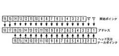
本例では、開始ポインタおよび終了ポインタは16ビット・ポインタであると仮定される。レジスタ83は、16ビットの書き込みポインタ、すなわちヘッド・ポインタである。16ビット・ポインタは、レジスタ87および88に開始ポインタおよび終了ポインタをロードするための16ビット・バスまたは8ビット・バスの使用を容易にするために選択されている。一方、メモリ18は18ビット・アドレスを有する。18ビットの書き込みアドレスは、結合された18ビットの書き込みアドレスの最上位のビット位置に開始ポインタ・ビットを有する16ビットのヘッド・ポインタに開始ポインタの最上位の2ビットを連結することによって形成される。開始ポインタは、それぞれのレジスタ87によってサービス・ポインタ・コントローラ93に供給される。サービス・ポインタ・コントローラは、レジスタ87に記憶された開始ポインタからより上位の(more significant)開始ポインタ・ビットを解析(parse)し、これらのビットを16ビットのヘッド・ポインタ・バスに関連付ける。このことは、マルチプレクサ85を出るヘッド・ポインタ・バスと結合されていることが示されるバス96によって、かつ、図8の太い矢印によって示されている。 In this example, it is assumed that the start pointer and end pointer are 16-bit pointers. The register 83 is a 16-bit write pointer, that is, a head pointer. The 16-bit pointer has been selected to facilitate the use of a 16-bit or 8-bit bus to load the
図8では、ボックスの最上部、中間および最下部の行は、開始ポインタ、アドレスおよびヘッドまたはテール・ポインタのビットをそれぞれ表している。より高位に番号付けられているボックスはより上位のビット位置(more significant bit position)を表している。矢印は、それぞれのアドレスのビットが開始ポインタまたはヘッド/テール・ポインタのどのビット位置から得られるかを示している。本展開(derivation)において、太い矢印は定常動作を表している。 In FIG. 8, the top, middle and bottom rows of the box represent the start pointer, address and head or tail pointer bits, respectively. The boxes numbered higher represent the more significant bit positions. The arrows indicate from which bit position of the start pointer or head / tail pointer each address bit is derived. In this derivation, a thick arrow represents a steady operation.
同様に、メモリ読み出しポインタまたはテール・ポインタは、加算器79およびサービス・テール・レジスタ92によって発生される。各潜在的なプログラム・コンポーネントに対してサービス・テール・レジスタがある。読み出しまたはテール・ポインタ値はレジスタ92に記憶され、メモリ読み出しサイクル中にアドレス・マルチプレクサ105に供給される。1単位だけ増分されるテール・ポインタは、加算器79にも結合され、増分されたポインタは次の読み出しサイクルの間、適当なレジスタ92に記憶される。レジスタ92は、現在サービスされている適当なプログラム・コンポーネントのためのサービス・ポインタ・コントローラ93によって選択される。 Similarly, a memory read pointer or tail pointer is generated by adder 79 and
レジスタ92は16ビットのテール・ポインタを供給する。18ビットの読み出しアドレスは、結合された18ビットの書き込みアドレスの最上位のビット位置に開始ポインタ・ビットを有する16ビットのテール・ポインタに開始ポインタの最上位の2ビットを連結することによって形成される。サービス・ポインタ・コントローラは、レジスタ87に記憶された開始ポインタからより上位の開始ポインタ・ビットを解析し、これらのビットを16ビットのヘッド・ポインタ・バスに関連付ける。このことは、マルチプレクサ90を出るテール・ポインタ・バスと結合されているバス94によって示されている。
データは計算されたアドレスでメモリ18に記憶されている。1バイトのデータを記憶した後、ヘッド・ポインタは、1だけ増分され、このプログラム・コンポーネントのための終了ポインタと比較され、これらが等しいならば、ヘッド・ポインタのもっと有意なビットが開始ポインタの下位14ビットと取り換えられ、0がアドレスのヘッド・ポインタ部の下位2ビット位置に置かれる。このことは、開始ポインタとアドレスとの間のハッチされた矢印に関して図8に示されている。この動作は、サービス・ポインタ・コントローラ93からマルチプレクサ85からのヘッド・ポインタ・バスを指示する矢印97によって示される。下位14の開始ポインタ・ビットを供給することによって、ヘッド・ポインタ・ビットを無効にする(override)と仮定する。この1書き込みサイクルの間、ヘッド・ポインタ・ビットをアドレスの下位開始ポインタ・ビットと取り換えることによって、メモリは、上位の2開始ポインタ・ビットで指定されたメモリ・ブロックを通してスクロールし、したがって、ブロック内の独自のメモリ・ロケーションのための各パケットの開始での書き込みアドレスの再プログラミングを不要にする。 The data is stored in the
ヘッド・ポインタが常にテール・ポインタ(メモリ18からデータをどこに読み出すかを指示するために使用される)に等しいならば、ヘッド・テール・クラッシュが発生したことを示す信号がマイクロプロセッサの割り込み部に送られる。このプログラム・チャネルからメモリ18にさらに書き込むことは、マイクロプロセッサがチャネルを再使用可能にするまで、不能にされる。この場合は非常にまれであり、通常動作中、発生すべきでない。 If the head pointer is always equal to the tail pointer (used to indicate where to read data from the memory 18), a signal indicating that a head tail crash has occurred is sent to the microprocessor interrupt. Sent. Further writing to
データは、加算器79およびレジスタ92によって計算されたアドレスに従って、それぞれの信号プロセッサの要求でメモリ18から検索される。1バイトの記憶データを読み出した後、テール・ポインタは、1単位だけ増分され、サービス・ポインタ・コントローラ93においてこの論理チャネルのためのエンド・ポインタと比較される。テール・ポインタおよびエンド・ポインタが等しいならば、テール・ポインタのより上位のビットは下位の14ビットの開始ポインタと取り換えられ、0がアドレスのテール・ポインタ部の下位の2ビット位置に置かれる。これは、コントローラ93から出て、マルチプレクサ90からのテール・ポインタ・バスを指示する矢印95によって示されている。いま、テール・ポインタがヘッド・ポインタに等しいならば、それぞれのメモリ・ブロックは空として規定される。そして、より多くのデータがこのプログラム・チャネルのためにFECから受信されるまで、これ以上のバイトは関連する信号プロセッサに送られない。それぞれの書き込みアドレスまたは読み出しアドレスのヘッド・ポインタ部またはテール・ポインタ部をスタート・ポインタの下位14ビットで実際に置き換えることは、適当な多重化または3状態の相互接続の使用によって達成される。 Data is retrieved from
メモリ読み出し/書き込み制御は、サービス・ポインタ・コントローラおよび直接メモリ・アクセスDMA、要素93および94によって実行される。DMAは読み出しサイクルおよび書き込みサイクルをスケジュールするようにプログラムされる。スケジューリングは、FEC12がメモリに書き込まれるデータを供給しているか否かによる。いかなる入力信号・コンポーネント・データが消失されないようにFECデータ書き込み動作が優先する。図7に示された典型的な装置では、メモリをアクセスできる4つの種類の装置がある。これらは、スマート・カード、FEC(より正確には、暗号解読器16)、マイクロプロセッサ19およびオーディオ・プロセッサおよびビデオ・プロセッサのようなアプリケーション・デバイスである。メモリ競合(memory contention)は下記のように処理される。上記の様々な処理要素からのデータ要求に応答して、DMAは、それぞれのプログラム・コンポーネントに対するメモリのブロックを割り当てる。メモリへのアクセスは、その間に1バイトのデータがメモリ18から読み出されるかまたはメモリ18に書き込まれる95nSタイム・スロットで実現できる。“FECがデータを供給していること”または”FECがデータを供給していないこと”のそれぞれで規定される2つの主要なアクセス割り当て(access allocation)モードがある。これらのモードの各々に関して、最大5Mバイト/秒のFECデータ速度、すなわち各200nSに対して1バイトと仮定すると、タイム・スロットは下記のように割り当てられ、優先順位が付けられる。これらは、FECがデータを供給している場合
1)EECデータ書き込み;
2)アプリケーション・デバイス読み出し/マイクロプロセッサ読み出し/書き込み;
3)FECデータ書き込み;
4)マイクロプロセッサ読み出し/書き込み;
および
FECがデータ供給していない場合
1)スマート・カード読み出し/書き込み;
2)アプリケーション・デバイス置読み出し/マイクロプロセッサ読み出し/書き込み;
3)スマート・カード読み出し/書き込み;
4)マイクロプロセッサ読み出し/書き込み。
である。Memory read / write control is performed by the service pointer controller and direct memory access DMA,
2) Application device read / microprocessor read / write;
3) FEC data write;
4) Microprocessor read / write;
And if the FEC is not supplying data 1) Smart card read / write;
2) Application device read / microprocessor read / write;
3) Smart card read / write;
4) Microprocessor read / write.
It is.
FECデータ書き込みは延期することができないために、FEC(すなわち、より正確には暗号解読器)は、データを提供している場合、各200nS期間中メモリ・アクセスを保証しなければならない。交互のタイム・スロットがアプリケーション・デバイスおよびマイクロプロセッサによって共有される。要求デバイス(requesting device)に対して供給可能であるいかなるデータもないとき、マイクロプロセッサはアプリケーション・タイム・スロットの使用を実現する。 Because FEC data writes cannot be deferred, the FEC (ie, more precisely, the decryptor) must guarantee memory access during each 200 nS period when providing data. Alternate time slots are shared by the application device and the microprocessor. When there is no data that can be supplied to the requesting device, the microprocessor realizes the use of the application time slot.
コントローラ93は、SCID検出器と通信して、メモリ書き込み動作の間、それぞれの開始ポインタ・レジスタ、ヘッド・ポインタ・レジスタおよび終了ポインタ・レジスタのどれにアクセスするかを決定する。コントローラ93は、DMAと通信して、メモリ読み出し動作の間、それぞれの開始レジスタ、終了レジスタおよびテールレジスタのどれにアクセスするかを決定する。DMA98は、マルチプレクサ99、104および105によって対応するアドレスおよびデータの選択を制御する。
図9は、DMA98のメモリ・アクセス処理の典型的なフローチャートを示す。DMAは、SCIDの検出によって受信パケットの検出または非検出に応答する{200}。メモリに書き込まれる暗号解読器16からのデータの存在を示すSCIDが検出されたならば、暗号解読器からの1バイトのプログラム・データはバッファ・メモリ18に書き込まれる{201}。書き込まれるメモリのブロックは、現SCIDに応答するプロセッサ93によって決定される。次に、スマート・カードおよびμPCを含むプログラム・コンポーネント・プロセッサのいずれかがデータまたはメモリ18への読み出し/書き込み(R/W)アクセスを要求しているか否かを決定する{202}。いかなるデータ要求もDMAで行われていないならば、処理はステップに戻る{200}。データR/W要求が行われていたならば、DMAは要求の優先順位を決定する{203}。これは、従来の割り込みルーチンによってまたは、その代わりに、データを要求するこれらのプログラム・プロセッサの任意の順序のシーケンシャル1バイト・サービスによって達成される。例えば、任意のアクセス優先順位はビデオ、オーディオI、オーディオII、スマート・カード、およびμPCであると仮定する。ビデオ、オーディオIIおよびμPCだけがメモリ・アクセスを要求していることも仮定する。現ステップの動作中{203}、1バイトのビデオがメモリから読み出される。次のステップ動作中{203}、1バイトのオーディオIIがメモリから読み出され、次のその後のステップの発生中{203}、1バイトのμPCデータはメモリ18に書き込まれ、またはメモリ18から読み出される等である。スマート・カードおよびμPCアクセスのためのアドレスは、スマート・カードおよびμPCのそれぞれによって提供されるが、ビデオ、オーディオおよびプログラム・ガイドのためのアドレスはアドレス・ポインタ装置(80〜93)から供給されることに注目すべきである。 FIG. 9 shows a typical flowchart of the
一旦優先アクセスが確立されると{203}、必要なプログラム・プロセッサは、メモリ18に書き込まれるかまたはメモリ18から読み出される1バイトのデータによってサービスされる{204}。次に、暗号解読器16からの1バイトのデータはメモリに書き込まれる{205}。μPCがアクセスを要求しているかどうかを決定するための検査{206}が行われる。μPCがアクセスを要求しているならば、1バイトのデータによってサービスされる{207}。μPCがアクセスを要求していないならば、処理は、プログラム・プロセッサのいずれかアクセスを要求するかどうかを決定するためにステップ{202}にジャンプする。このように、入力データ(incoming data)は常に他のメモリ・アクセス期間(memory access period)へのアクセスが保証され、介在するメモリ・アクセス期間はプログラム・プロセッサの間で広げられる。 Once preferential access is established {203}, the required program processor is serviced by one byte of data written to or read from memory 18 {204}. Next, 1 byte of data from the
暗号解読器16からデータが現在得られないならば、すなわち、SCIDは現在検出されないならば、処理{208〜216}が後に続く。最初に、スマート・カードは、メモリ・アクセスを要求しているか否かを決定するために検査される{208}。要求しているならば、1バイトのメモリ・アクセスが与えられ{209}、そうでないときには、プログラム・プロセッサのいずれかがメモリ・アクセスを要求しているか否かを決定するために検査が行われる{210}。データR/W要求が行われたならば、DMAは、要求の優先順位を決定する{211}。適当なプロセッサは、1バイトのメモリ読み出しまたは書き込みアクセスによってサービスされる{212}。データR/W要求がプログラム・プロセッサによって行われないならば、処理は、スマート・カードがメモリ・アクセスを要求しているか否かを決定するためにテストが実行されるステップ{213}にジャンプする。要求しているならば、スマート・カードは1バイトのメモリ・アクセスによってサービスされ{216}、そうでないと、処理はステップ{200}にジャンプする。 If no data is currently available from the
この好ましい例では、“FECがデータを供給していない”モードでは、スマート・カードは全ての他のプログラム・プロセッサよりも2対1のアクセス優先順位(access precedence)が与えられる。この優先権は、DMA装置内のプログラマブル・ステートマシンにプログラムされ、μPCによって変更される。前述のように、本システムはインタアクティブ・サービスを提供することを意図され、μPC19は、インタアクティブ・データに応答して、少なくとも一部はインタアクティブ動作を実行する。この役割では、μPC19は、アプリケーション・ストレージおよび作業メモリの両方に対してメモリ18を使用する。これらの例では、システム・オペレータは、μPC19により大きな周波数のメモリ・アクセスを与えるためにメモリ・アクセス優先順位を変えることができる。メモリ・アクセス優先順位の再プログラミングを、インタアクティブ・アプリケーション命令のサブセットとして含むことができる。 In this preferred example, in the “FEC is not supplying data” mode, the smart card is given a 2: 1 access precedence over all other program processors. This priority is programmed into the programmable state machine in the DMA device and is changed by the μPC. As described above, the present system is intended to provide interactive services, and the
パケットが消失された場合、メディア・エラー・コードをビデオ・コンポーネント信号ストリームに挿入し、特定の信号エントリ・ポイントがデータ・ストリームで発生されるまで、伸長を中断するようにビデオ信号伸長器を条件付けることは有利なことである。どこで、どのビデオ・パケットで次のエントリ・ポイントが発生できるかを予測することは実際的でない。できるだけ高速に次のエントリ・ポイントを探すために、パケットが消失されたことを検出した後の最初のビデオ・パケットの始めでメディア・エラー・コードを含むことが必要である。図7の回路は、各ビデオ・パケットの始めにメディア・エラー・コードを置き、次に、直前のパケットのいかなる消失もない場合、それぞれのパケットのメディア・エラー・コードを削除する。メディア・エラー・コードは、暗号解読器から受信するビデオ・ペイロードより先にM書き込みサイクルの間、メモリ18に書き込むことにより、現ビデオ・パケット・ペイロードのために備えてある第1のM個のメモリ・アドレス・ロケーションに挿入される。同時に、マルチプレクサ99は、発生源100からのメディア・エラー・コードをメモリ18のI/Oに与えるようにDMA98によって条件付けられる。Mは、単に、メディア・エラー・コードを記憶するのに必要な整数のメモリ・ロケーションである。メモリは8ビット・バイトを記憶するものであり、メディア・エラー・コードは32ビットであると仮定すると、Mは4に等しい。 If a packet is lost, insert a media error code into the video component signal stream and condition the video signal decompressor to suspend decompression until a specific signal entry point is generated in the data stream It is advantageous to apply it. It is impractical to predict where and in which video packet the next entry point can occur. In order to find the next entry point as fast as possible, it is necessary to include a media error code at the beginning of the first video packet after detecting that the packet has been lost. The circuit of FIG. 7 places a media error code at the beginning of each video packet and then deletes the media error code of each packet if there is no loss of the previous packet. The media error code is written to
メモリにメディア・エラー・コードをロードするためのアドレスは、マルチプレクサ82およびマルチプレクサ85を介して、それぞれのビデオ・コンポーネントサービス・レジスタ83によって供給される。ビデオ・コンポーネント・データでロードされるメモリ・ロケーションにメディア・エラー・コードをロードするためのポインタ・レジスタ83から供給された第1のM個のアドレスは単に、通常ビデオ・ヘッド・ポインタによって発生される次のM個のシーケンシャル・アドレスであることが理解される。これらの同一アドレスはM段の遅延素子84に結合されるので、メディア・エラー・コードの最後のバイトがメモリ18に記憶された直後、第1のM個のアドレスは遅延素子84の出力として得られる。 The address for loading the media error code into the memory is provided by the respective video component service register 83 via multiplexer 82 and multiplexer 85. The first M addresses supplied from the pointer register 83 for loading the media error code into the memory location loaded with video component data are simply generated by the normal video head pointer. Is understood to be the next M sequential addresses. Since these same addresses are coupled to the M
メディア・エラー・コードをメモリにロードするためのタイミングは消失パケットの決定と一致する。パケット・エラーまたは消失検出は、現パケットのCCおよびHDデータに応答するエラー検出器101によって実行される。 The timing for loading the media error code into memory is consistent with the lost packet determination. Packet error or loss detection is performed by the
パケット消失が検出されたならば、現パケットのビデオ・コンポーネントは、次のアドレス・ロケーション、すなわち(M+1)番目のアドレス・ロケーションで始まるメモリ18に記憶される。これは、適当なレジスタ83から遅延されないヘッド・ポインタを送り続けるようにマルチプレクサ85を条件付けることによって達成される。一方、パケット消失が検出されないならば、現パケットにおけるビデオ・コンポーネントの第1のMバイトは、メディア・エラー・コードが直前に記憶されたメモリ・ロケーションに記憶される。 If a packet loss is detected, the video component of the current packet is stored in
パケット・エラーまたは消失検出は、現パケットのCCおよびHDデータに応答するエラー検出器101によって実行される。検出器101は、現パケットの連続カウント(continuity count)CCが前のパケットのCCと1単位(unit)だけ異なるか否かを決定するために、現パケットの連続カウントCCを検査する。さらに、現パケットのTOGGLE(トグル)ビットが検査され、それがそれぞれのビデオ・フレームに対して適切な状態を示しているか否かを決定する。CC値が不正確であるならば、TOGGLEビットの状態が検査される。CCおよびTOGGLEビットの一方または両方がエラーであるか否かに応じて、第1または第2のエラー修復(error remediation)モードがそれぞれ実行される。誤っているCCおよびTOGGLEビットの両方によって開始される第2のモードにおいて、本システムは画像層ヘッダ(picture layer header)を含むパケットにリセットされるように条件付けられる。CCだけが誤っている第1のモードでは、本システムはスライス層ヘッダ(slice layer header)を含むパケットにリセットされるように条件付けられる。(スライス層は、フレーム内の圧縮データのサブセットである。)第1および第2のモードの両方では、メモリに書き込まれたメディア・エラー・コードは、訂正動作(remedial action)を実行するよう伸長器(decompressor)に報知するために、それぞれのペイロードに保持される。 Packet error or loss detection is performed by the
SCID検出器、暗号解読器、アドレス指定回路、条件付きアクセス・フィルタ、およびスマート・カード・インターフェスは全て単一の集積回路上に含まれるようにシステムを分割することは特に有効であることが分かった。これは、臨界的なタイミング制約をもたらす外部経路の数を制限する。 It may be particularly effective to partition the system so that the SCID detector, decryptor, addressing circuit, conditional access filter, and smart card interface are all contained on a single integrated circuit. I understood. This limits the number of external paths that result in critical timing constraints.
10 チューナ検出器
12 FEC
13 プログラマブルSCIDレジスタ
15 SCID一致検出
16 暗号解読器
30 Eコード・デコーダ
31 スマート・カード10
13
Claims (1)
Translated fromJapanese複数のトランスポート・パケットからなるパケット化トランスポート・ストリームを受信する手段と、
前記パケット化トランスポート・ストリーム内の、プログラムとパケット識別子との関係を示すデータに基づいて、選択されたプログラムと関連するトランスポート・パケットを識別するためのパケット識別子を割り出す手段と、
前記パケット識別子との一致検出器をプログラムする手段と、
前記プログラムされた一致検出器を用いて前記パケット化トランスポート・ストリームを解析し、前記パケット識別子に応じて、所望の一連のトランスポート・パケットを特定して取得する手段と、
前記取得した一連のトランスポート・パケットの各々のパケットの中で、前記トランスポート・パケットのエラー情報を提供する1ビットのトグル部を検出する手段と、
前記1ビットのトグル部の状態に応じて前記トランスポート・パケットに特定のタイプのエラーが存在するかどうかを判定する手段と、
前記取得した一連のトランスポート・パケットを処理する手段と、
を備える、前記装置。A device for processing a packetized transport stream comprising:
Means for receiving a packetized transport stream comprising a plurality of transport packets;
Means for determininga packet identifier for identifying a transport packet associated with the selected program based on data indicating a relationship between the program and the packet identifier in the packetized transport stream;
Means for programming a match detector with said packet identifier;
Means for analyzing the packetized transport stream using the programmed match detector and identifying and obtaining a desired series of transport packets according to the packet identifier;
Means for detecting a 1-bit toggle portion providing error information of the transport packet in each packet of the acquired series of transport packets;
Means for determining whether a certain type of error exists in the transport packet according to the state of the 1-bit toggle portion;
Means for processing the obtained series of transport packets;
Comprising the apparatus.
Applications Claiming Priority (2)
| Application Number | Priority Date | Filing Date | Title |
|---|---|---|---|
| US232,794 | 1994-04-22 | ||
| US08/232,794US5619501A (en) | 1994-04-22 | 1994-04-22 | Conditional access filter as for a packet video signal inverse transport system |
Related Parent Applications (1)
| Application Number | Title | Priority Date | Filing Date |
|---|---|---|---|
| JP2011106451ADivisionJP5182966B2 (en) | 1994-04-22 | 2011-05-11 | How to process packetized transport streams |
Related Child Applications (1)
| Application Number | Title | Priority Date | Filing Date |
|---|---|---|---|
| JP2011149984ADivisionJP5182969B2 (en) | 1994-04-22 | 2011-07-06 | How to process packetized transport streams |
Publications (2)
| Publication Number | Publication Date |
|---|---|
| JP2011193533A JP2011193533A (en) | 2011-09-29 |
| JP5182967B2true JP5182967B2 (en) | 2013-04-17 |
Family
ID=22874615
Family Applications (26)
| Application Number | Title | Priority Date | Filing Date |
|---|---|---|---|
| JP52763595AExpired - LifetimeJP4316008B2 (en) | 1994-04-22 | 1995-03-15 | Conditional access information arrangement |
| JP2007276897AExpired - LifetimeJP4122370B2 (en) | 1994-04-22 | 2007-10-24 | Conditional access information arrangement |
| JP2008140240AExpired - LifetimeJP4535344B2 (en) | 1994-04-22 | 2008-05-29 | How to process packetized transport streams |
| JP2008140239AExpired - LifetimeJP4404271B2 (en) | 1994-04-22 | 2008-05-29 | How to process packetized transport streams |
| JP2009131758AGrantedJP2009194935A (en) | 1994-04-22 | 2009-06-01 | Conditional access information arrangement |
| JP2009219983AExpired - LifetimeJP4420298B2 (en) | 1994-04-22 | 2009-09-25 | How to process packetized data streams |
| JP2009220003AExpired - LifetimeJP4458438B2 (en) | 1994-04-22 | 2009-09-25 | How to process packetized data streams |
| JP2009222719AExpired - LifetimeJP4475475B2 (en) | 1994-04-22 | 2009-09-28 | How to process packetized data streams |
| JP2009244330AExpired - LifetimeJP4475476B2 (en) | 1994-04-22 | 2009-10-23 | How to process packetized data streams |
| JP2009263848AExpired - LifetimeJP4582670B2 (en) | 1994-04-22 | 2009-11-19 | How to process packetized data streams |
| JP2010005763AExpired - LifetimeJP5131867B2 (en) | 1994-04-22 | 2010-01-14 | How to process packetized data streams |
| JP2010107049AExpired - LifetimeJP4748623B2 (en) | 1994-04-22 | 2010-05-07 | How to generate and send a packetized transport stream |
| JP2011037093AExpired - LifetimeJP4863328B2 (en) | 1994-04-22 | 2011-02-23 | How to process packetized transport streams |
| JP2011037097AExpired - LifetimeJP5331140B2 (en) | 1994-04-22 | 2011-02-23 | How to process packetized transport streams |
| JP2011062731AExpired - LifetimeJP5131874B2 (en) | 1994-04-22 | 2011-03-22 | Packetized transport stream processing unit |
| JP2011090739AExpired - LifetimeJP4953262B2 (en) | 1994-04-22 | 2011-04-15 | Packetized transport stream processing unit |
| JP2011106451AExpired - LifetimeJP5182966B2 (en) | 1994-04-22 | 2011-05-11 | How to process packetized transport streams |
| JP2011128120AExpired - LifetimeJP5182967B2 (en) | 1994-04-22 | 2011-06-08 | Packetized transport stream processing unit |
| JP2011149984AExpired - LifetimeJP5182969B2 (en) | 1994-04-22 | 2011-07-06 | How to process packetized transport streams |
| JP2012264843AExpired - LifetimeJP5441134B2 (en) | 1994-04-22 | 2012-12-04 | How to process packetized data streams |
| JP2013219823AExpired - LifetimeJP5441138B2 (en) | 1994-04-22 | 2013-10-23 | How to process packetized transport streams |
| JP2013219824AExpired - LifetimeJP5574462B2 (en) | 1994-04-22 | 2013-10-23 | How to process packetized transport streams |
| JP2013219826AExpired - LifetimeJP5441140B2 (en) | 1994-04-22 | 2013-10-23 | How to process packetized transport streams |
| JP2013219827AExpired - LifetimeJP5574463B2 (en) | 1994-04-22 | 2013-10-23 | How to process packetized transport streams |
| JP2013219828APendingJP2014045502A (en) | 1994-04-22 | 2013-10-23 | Apparatus for processing packetized transport stream |
| JP2013219825AExpired - LifetimeJP5441139B2 (en) | 1994-04-22 | 2013-10-23 | How to process packetized transport streams |
Family Applications Before (17)
| Application Number | Title | Priority Date | Filing Date |
|---|---|---|---|
| JP52763595AExpired - LifetimeJP4316008B2 (en) | 1994-04-22 | 1995-03-15 | Conditional access information arrangement |
| JP2007276897AExpired - LifetimeJP4122370B2 (en) | 1994-04-22 | 2007-10-24 | Conditional access information arrangement |
| JP2008140240AExpired - LifetimeJP4535344B2 (en) | 1994-04-22 | 2008-05-29 | How to process packetized transport streams |
| JP2008140239AExpired - LifetimeJP4404271B2 (en) | 1994-04-22 | 2008-05-29 | How to process packetized transport streams |
| JP2009131758AGrantedJP2009194935A (en) | 1994-04-22 | 2009-06-01 | Conditional access information arrangement |
| JP2009219983AExpired - LifetimeJP4420298B2 (en) | 1994-04-22 | 2009-09-25 | How to process packetized data streams |
| JP2009220003AExpired - LifetimeJP4458438B2 (en) | 1994-04-22 | 2009-09-25 | How to process packetized data streams |
| JP2009222719AExpired - LifetimeJP4475475B2 (en) | 1994-04-22 | 2009-09-28 | How to process packetized data streams |
| JP2009244330AExpired - LifetimeJP4475476B2 (en) | 1994-04-22 | 2009-10-23 | How to process packetized data streams |
| JP2009263848AExpired - LifetimeJP4582670B2 (en) | 1994-04-22 | 2009-11-19 | How to process packetized data streams |
| JP2010005763AExpired - LifetimeJP5131867B2 (en) | 1994-04-22 | 2010-01-14 | How to process packetized data streams |
| JP2010107049AExpired - LifetimeJP4748623B2 (en) | 1994-04-22 | 2010-05-07 | How to generate and send a packetized transport stream |
| JP2011037093AExpired - LifetimeJP4863328B2 (en) | 1994-04-22 | 2011-02-23 | How to process packetized transport streams |
| JP2011037097AExpired - LifetimeJP5331140B2 (en) | 1994-04-22 | 2011-02-23 | How to process packetized transport streams |
| JP2011062731AExpired - LifetimeJP5131874B2 (en) | 1994-04-22 | 2011-03-22 | Packetized transport stream processing unit |
| JP2011090739AExpired - LifetimeJP4953262B2 (en) | 1994-04-22 | 2011-04-15 | Packetized transport stream processing unit |
| JP2011106451AExpired - LifetimeJP5182966B2 (en) | 1994-04-22 | 2011-05-11 | How to process packetized transport streams |
Family Applications After (8)
| Application Number | Title | Priority Date | Filing Date |
|---|---|---|---|
| JP2011149984AExpired - LifetimeJP5182969B2 (en) | 1994-04-22 | 2011-07-06 | How to process packetized transport streams |
| JP2012264843AExpired - LifetimeJP5441134B2 (en) | 1994-04-22 | 2012-12-04 | How to process packetized data streams |
| JP2013219823AExpired - LifetimeJP5441138B2 (en) | 1994-04-22 | 2013-10-23 | How to process packetized transport streams |
| JP2013219824AExpired - LifetimeJP5574462B2 (en) | 1994-04-22 | 2013-10-23 | How to process packetized transport streams |
| JP2013219826AExpired - LifetimeJP5441140B2 (en) | 1994-04-22 | 2013-10-23 | How to process packetized transport streams |
| JP2013219827AExpired - LifetimeJP5574463B2 (en) | 1994-04-22 | 2013-10-23 | How to process packetized transport streams |
| JP2013219828APendingJP2014045502A (en) | 1994-04-22 | 2013-10-23 | Apparatus for processing packetized transport stream |
| JP2013219825AExpired - LifetimeJP5441139B2 (en) | 1994-04-22 | 2013-10-23 | How to process packetized transport streams |
Country Status (13)
| Country | Link |
|---|---|
| US (4) | US5619501A (en) |
| EP (2) | EP0858222B1 (en) |
| JP (26) | JP4316008B2 (en) |
| KR (3) | KR100392025B1 (en) |
| CN (3) | CN1110200C (en) |
| CA (1) | CA2188127C (en) |
| DE (1) | DE69505369T2 (en) |
| ES (2) | ES2162397T3 (en) |
| MX (1) | MX9604992A (en) |
| MY (2) | MY113950A (en) |
| SG (1) | SG71707A1 (en) |
| TW (1) | TW237582B (en) |
| WO (1) | WO1995029560A1 (en) |
Cited By (1)
| Publication number | Priority date | Publication date | Assignee | Title |
|---|---|---|---|---|
| JP2014053934A (en)* | 1994-04-22 | 2014-03-20 | Thomson Consumer Electronics Inc | Method for processing packetized transport stream |
Families Citing this family (135)
| Publication number | Priority date | Publication date | Assignee | Title |
|---|---|---|---|---|
| US6292568B1 (en) | 1966-12-16 | 2001-09-18 | Scientific-Atlanta, Inc. | Representing entitlements to service in a conditional access system |
| US7168084B1 (en) | 1992-12-09 | 2007-01-23 | Sedna Patent Services, Llc | Method and apparatus for targeting virtual objects |
| US9286294B2 (en) | 1992-12-09 | 2016-03-15 | Comcast Ip Holdings I, Llc | Video and digital multimedia aggregator content suggestion engine |
| DE69522924T2 (en)* | 1994-10-11 | 2002-04-11 | Koninklijke Philips Electronics N.V., Eindhoven | METHOD AND ARRANGEMENT FOR TRANSMITTING AN INTERACTIVE AUDIOVISUAL PROGRAM |
| US6424717B1 (en) | 1995-04-03 | 2002-07-23 | Scientific-Atlanta, Inc. | Encryption devices for use in a conditional access system |
| US8548166B2 (en)* | 1995-04-03 | 2013-10-01 | Anthony J. Wasilewski | Method for partially encrypting program data |
| US6937729B2 (en) | 1995-04-03 | 2005-08-30 | Scientific-Atlanta, Inc. | Representing entitlements to service in a conditional access system |
| US7224798B2 (en) | 1995-04-03 | 2007-05-29 | Scientific-Atlanta, Inc. | Methods and apparatus for providing a partial dual-encrypted stream in a conditional access overlay system |
| US6252964B1 (en) | 1995-04-03 | 2001-06-26 | Scientific-Atlanta, Inc. | Authorization of services in a conditional access system |
| US6246767B1 (en) | 1995-04-03 | 2001-06-12 | Scientific-Atlanta, Inc. | Source authentication of download information in a conditional access system |
| US6560340B1 (en) | 1995-04-03 | 2003-05-06 | Scientific-Atlanta, Inc. | Method and apparatus for geographically limiting service in a conditional access system |
| US5920572A (en)* | 1995-06-30 | 1999-07-06 | Divicom Inc. | Transport stream decoder/demultiplexer for hierarchically organized audio-video streams |
| US7562392B1 (en)* | 1999-05-19 | 2009-07-14 | Digimarc Corporation | Methods of interacting with audio and ambient music |
| FR2740636B1 (en)* | 1995-10-31 | 1997-11-28 | Thomson Multimedia Sa | PROCESS ALLOWING THE CASCADE OF DETACHABLE CONDITIONAL ACCESS MODULES, CIRCUIT FOR INSERTING A PREDEFINED SEQUENCE AND DETECTION CIRCUIT OF THE SAID SEQUENCE FOR THE IMPLEMENTATION OF THE PROCEDURE |
| US5893132A (en) | 1995-12-14 | 1999-04-06 | Motorola, Inc. | Method and system for encoding a book for reading using an electronic book |
| US5835493A (en)* | 1996-01-02 | 1998-11-10 | Divicom, Inc. | MPEG transport stream remultiplexer |
| KR100192504B1 (en)* | 1996-01-05 | 1999-06-15 | 구자홍 | The data input-output apparatus of mpeg2 transport decoder |
| FR2751154B1 (en)* | 1996-07-15 | 1998-09-11 | Schlumberger Ind Sa | INFORMATION DIVERSIFICATION SYSTEM IN A PRODUCT OR SERVICE DISTRIBUTION NETWORK |
| US6366326B1 (en)* | 1996-08-01 | 2002-04-02 | Thomson Consumer Electronics Inc. | System for acquiring, processing, and storing video data and program guides transmitted in different coding formats |
| US5946045A (en)* | 1996-08-01 | 1999-08-31 | Thomson Consumer Electronics, Inc. | System for forming program guides and video data for storage and transmission in different coding formats |
| US6414726B1 (en)* | 1996-11-01 | 2002-07-02 | Texas Instruments Incorporated | Device for identifying packets of digital data and a receiver for digital television signals equipped with such a device |
| DE19710972A1 (en)* | 1997-03-17 | 1998-10-01 | Ulrich Kretzschmar | Method and device for data transmission |
| ID23380A (en)* | 1997-03-21 | 2000-04-20 | Canal & Siciete Anonyme | METHODS AND APARATUS FOR PREVENTING CHEAT ACCESS IN REQUIRED ACCESS SYSTEMS |
| EP0986215A4 (en)* | 1997-04-01 | 2007-01-31 | Matsushita Electric Industrial Co Ltd | DIGITAL COMMUNICATION SYSTEM, TRANSMITTER, AND DATA SELECTOR |
| AU4650297A (en)* | 1997-04-14 | 1998-11-11 | Thomson Consumer Electronics, Inc | System for automatically forming a program guide from information derived from multiple sources |
| JP3356203B2 (en)* | 1997-06-09 | 2002-12-16 | 日本電気株式会社 | MPEG2 transport stream separation method and circuit |
| US6462791B1 (en)* | 1997-06-30 | 2002-10-08 | Intel Corporation | Constrained motion estimation and compensation for packet loss resiliency in standard based codec |
| EP0893921A1 (en)* | 1997-07-25 | 1999-01-27 | Scientific Atlanta, Inc. | Programmable two-level packet filter |
| US5948136A (en)* | 1997-07-30 | 1999-09-07 | Sony Corporation | Hardware authentication mechanism for transmission of data between devices on an IEEE 1394-1995 serial bus network |
| WO1999007145A1 (en)* | 1997-08-01 | 1999-02-11 | Scientific-Atlanta, Inc. | Verification of the source of program of information in a conditional access system |
| EP1010324A1 (en)* | 1997-08-01 | 2000-06-21 | Scientific-Atlanta, Inc. | Representing entitlements to service in a conditional access system |
| JP3654342B2 (en)* | 1997-08-01 | 2005-06-02 | サイエンティフィック−アトランタ, インコーポレイテッド | Method and apparatus for geographically limiting service in a conditional access system |
| EP1000509B1 (en)* | 1997-08-01 | 2002-11-27 | Scientific-Atlanta, Inc. | Encryption device for use in a conditional access system |
| JP2003521818A (en)* | 1997-08-01 | 2003-07-15 | サイエンティフィック−アトランタ, インコーポレイテッド | Authentication of services in conditional access systems |
| EP1189438A3 (en)* | 1997-08-01 | 2009-04-22 | Scientific-Atlanta, Inc. | Method and apparatus for geographically limiting service in a conditional access system |
| US7515712B2 (en) | 1997-08-01 | 2009-04-07 | Cisco Technology, Inc. | Mechanism and apparatus for encapsulation of entitlement authorization in conditional access system |
| EP1193974A3 (en)* | 1997-08-01 | 2009-04-08 | Scientific-Atlanta, Inc. | Representing entitlements to service in a conditional access system |
| US6356567B2 (en) | 1997-09-26 | 2002-03-12 | International Business Machines Corporation | Embedded clock recovery and difference filtering for an MPEG-2 compliant transport stream |
| US6078594A (en)* | 1997-09-26 | 2000-06-20 | International Business Machines Corporation | Protocol and procedure for automated channel change in an MPEG-2 compliant datastream |
| US6115422A (en)* | 1997-09-26 | 2000-09-05 | International Business Machines Corporation | Protocol and procedure for time base change in an MPEG-2 compliant datastream |
| US6195403B1 (en) | 1997-09-26 | 2001-02-27 | International Business Machines Corporation | Pulse generator for a voltage controlled oscillator |
| US6072771A (en)* | 1997-09-26 | 2000-06-06 | International Business Machines Corporation | Detection of errors in table data |
| US6181706B1 (en) | 1997-09-26 | 2001-01-30 | International Business Machines Corporation | Common buffer for multiple streams and control registers in an MPEG-2 compliant transport register |
| US6229801B1 (en) | 1997-09-26 | 2001-05-08 | International Business Machines Corporation | Delivery of MPEG2 compliant table data |
| US6275507B1 (en) | 1997-09-26 | 2001-08-14 | International Business Machines Corporation | Transport demultiplexor for an MPEG-2 compliant data stream |
| US6088357A (en)* | 1997-09-26 | 2000-07-11 | International Business Machines Corporation | Auxiliary transport assist processor especially for an MPEG-2 compliant decoder |
| US6091772A (en)* | 1997-09-26 | 2000-07-18 | International Business Machines, Corporation | Black based filtering of MPEG-2 compliant table sections |
| JP3389843B2 (en) | 1997-10-17 | 2003-03-24 | 日本電気株式会社 | Digital broadcast receiving system in information processing device |
| DE19745969C2 (en)* | 1997-10-17 | 2002-03-07 | Deutsche Telekom Ag | Method and device for forwarding certain data, in particular reception rights in a pay TV terminal |
| KR100610522B1 (en)* | 1997-11-04 | 2006-08-09 | 코닌클리케 필립스 일렉트로닉스 엔.브이. | Communication network using different transmission characteristics |
| KR100252972B1 (en)* | 1997-12-31 | 2000-04-15 | 구자홍 | Limited reception system |
| US6351474B1 (en) | 1998-01-14 | 2002-02-26 | Skystream Networks Inc. | Network distributed remultiplexer for video program bearing transport streams |
| US6292490B1 (en) | 1998-01-14 | 2001-09-18 | Skystream Corporation | Receipts and dispatch timing of transport packets in a video program bearing stream remultiplexer |
| US6195368B1 (en) | 1998-01-14 | 2001-02-27 | Skystream Corporation | Re-timing of video program bearing streams transmitted by an asynchronous communication link |
| US6246701B1 (en) | 1998-01-14 | 2001-06-12 | Skystream Corporation | Reference time clock locking in a remultiplexer for video program bearing transport streams |
| US6351471B1 (en) | 1998-01-14 | 2002-02-26 | Skystream Networks Inc. | Brandwidth optimization of video program bearing transport streams |
| US6263466B1 (en)* | 1998-03-05 | 2001-07-17 | Teledesic Llc | System and method of separately coding the header and payload of a data packet for use in satellite data communication |
| EP0964572A1 (en)* | 1998-06-08 | 1999-12-15 | CANAL+ Société Anonyme | Decoder and security module for a digital transmission system |
| US6535919B1 (en)* | 1998-06-29 | 2003-03-18 | Canon Kabushiki Kaisha | Verification of image data |
| FR2781324B1 (en)* | 1998-07-20 | 2000-09-08 | Sagem | METHOD FOR TECHNICAL UPDATING OF A PACKET BROADCAST DATA RECEIVER AND REMOVABLE COMPUTER MEDIA FOR IMPLEMENTING THE METHOD |
| US6754905B2 (en) | 1998-07-23 | 2004-06-22 | Diva Systems Corporation | Data structure and methods for providing an interactive program guide |
| EP1097587A1 (en) | 1998-07-23 | 2001-05-09 | Diva Systems Corporation | Interactive user interface |
| US9924234B2 (en) | 1998-07-23 | 2018-03-20 | Comcast Ip Holdings I, Llc | Data structure and methods for providing an interactive program |
| DE29814544U1 (en) | 1998-08-13 | 1998-12-10 | media art Reinhold Geiling Agentur für Multi Media GmbH & Co. KG, 51149 Köln | Delivery of requested video sequences via satellites |
| JP2000092118A (en)* | 1998-09-08 | 2000-03-31 | Hitachi Ltd | Programmable network |
| FR2783335B1 (en)* | 1998-09-11 | 2000-10-13 | Thomson Multimedia Sa | METHOD FOR LOADING CONDITIONAL ACCESS SYSTEM FEES AND DEVICE IMPLEMENTING THE METHOD |
| JP2002536888A (en)* | 1999-01-28 | 2002-10-29 | コーニンクレッカ フィリップス エレクトロニクス エヌ ヴィ | Transmission system |
| FI106593B (en)* | 1999-02-15 | 2001-02-28 | Valtion Teknillinen | IP multicast service without return connection |
| JP4356131B2 (en)* | 1999-02-19 | 2009-11-04 | ソニー株式会社 | Digital broadcast transmission method and digital broadcast transmission apparatus |
| JP2000295594A (en)* | 1999-04-09 | 2000-10-20 | Pioneer Electronic Corp | Viewing control system for catv |
| US6711620B1 (en)* | 1999-04-14 | 2004-03-23 | Matsushita Electric Industrial Co. | Event control device and digital broadcasting system |
| US6754271B1 (en) | 1999-04-15 | 2004-06-22 | Diva Systems Corporation | Temporal slice persistence method and apparatus for delivery of interactive program guide |
| US6621870B1 (en)* | 1999-04-15 | 2003-09-16 | Diva Systems Corporation | Method and apparatus for compressing video sequences |
| US6904610B1 (en) | 1999-04-15 | 2005-06-07 | Sedna Patent Services, Llc | Server-centric customized interactive program guide in an interactive television environment |
| US7096487B1 (en) | 1999-10-27 | 2006-08-22 | Sedna Patent Services, Llc | Apparatus and method for combining realtime and non-realtime encoded content |
| AU5294200A (en)* | 1999-05-27 | 2000-12-18 | John S. Baras | 3d wavelet based video codec with human perceptual model |
| US6804782B1 (en) | 1999-06-11 | 2004-10-12 | General Instrument Corporation | Countermeasure to power attack and timing attack on cryptographic operations |
| US6317463B1 (en)* | 1999-06-14 | 2001-11-13 | Mitsubishi Electric Research Laboratories, Inc. | Method and apparatus for filtering data-streams |
| US6621817B1 (en)* | 1999-07-06 | 2003-09-16 | Texas Instruments Incorporated | Transport packet parser |
| UA69439C2 (en)* | 1999-07-09 | 2004-09-15 | Награвізьйон Са | System for performing purchase being influenced by the impulse for pay television |
| US6715076B1 (en)* | 1999-10-21 | 2004-03-30 | Koninklijke Philips Electronics N.V. | Video signal authentication system |
| DE60034364D1 (en) | 1999-10-27 | 2007-05-24 | Sedna Patent Services Llc | MULTIPLE VIDEO DRIVES USING SLICE BASED CODING |
| US9668011B2 (en)* | 2001-02-05 | 2017-05-30 | Avago Technologies General Ip (Singapore) Pte. Ltd. | Single chip set-top box system |
| US8284845B1 (en)* | 2000-01-24 | 2012-10-09 | Ati Technologies Ulc | Method and system for handling data |
| JP2001251568A (en)* | 2000-03-02 | 2001-09-14 | Pioneer Electronic Corp | Device and method for displaying program guide |
| US6898285B1 (en)* | 2000-06-02 | 2005-05-24 | General Instrument Corporation | System to deliver encrypted access control information to support interoperability between digital information processing/control equipment |
| WO2002025847A1 (en)* | 2000-09-21 | 2002-03-28 | Zydonik Aaron E | Satellite television distribution system |
| FI111423B (en)* | 2000-11-28 | 2003-07-15 | Nokia Corp | Arrangements for securing unencrypted data communication after channel change |
| US8103877B2 (en) | 2000-12-21 | 2012-01-24 | Digimarc Corporation | Content identification and electronic tickets, coupons and credits |
| JP2002247543A (en)* | 2001-02-21 | 2002-08-30 | Sony Corp | Transmitting device and method, receiving device and method, recording medium and program |
| US7793326B2 (en) | 2001-08-03 | 2010-09-07 | Comcast Ip Holdings I, Llc | Video and digital multimedia aggregator |
| US7908628B2 (en) | 2001-08-03 | 2011-03-15 | Comcast Ip Holdings I, Llc | Video and digital multimedia aggregator content coding and formatting |
| US8880709B2 (en)* | 2001-09-12 | 2014-11-04 | Ericsson Television Inc. | Method and system for scheduled streaming of best effort data |
| US7599369B2 (en)* | 2001-09-27 | 2009-10-06 | Broadcom Corporation | Apparatus and methods for hardware payload header suppression, expansion, and verification in a DOCSIS network |
| EP1320006A1 (en)* | 2001-12-12 | 2003-06-18 | Canal+ Technologies Société Anonyme | Processing data |
| FR2835371B1 (en)* | 2002-01-31 | 2004-04-16 | Viaccess Sa | METHOD AND DEVICE FOR TRANSMITTING ACCESS MESSAGE MANAGEMENT MESSAGE |
| US20040167925A1 (en)* | 2003-02-21 | 2004-08-26 | Visharam Mohammed Zubair | Method and apparatus for supporting advanced coding formats in media files |
| US7613727B2 (en)* | 2002-02-25 | 2009-11-03 | Sont Corporation | Method and apparatus for supporting advanced coding formats in media files |
| US20030163477A1 (en)* | 2002-02-25 | 2003-08-28 | Visharam Mohammed Zubair | Method and apparatus for supporting advanced coding formats in media files |
| CN100372379C (en)* | 2002-03-19 | 2008-02-27 | Nxp股份有限公司 | Conditional access control |
| US7831990B2 (en)* | 2002-04-29 | 2010-11-09 | Sony Corporation | Generic adaptation layer for JVT video |
| US20040006575A1 (en)* | 2002-04-29 | 2004-01-08 | Visharam Mohammed Zubair | Method and apparatus for supporting advanced coding formats in media files |
| US20030208777A1 (en)* | 2002-05-02 | 2003-11-06 | Daniel Danker | Addressed broadcast messaging |
| US20050068952A1 (en)* | 2002-05-24 | 2005-03-31 | Deiss Michael S. | Conditional access filter as for a packet video signal inverse transport system |
| US7849152B2 (en)* | 2002-06-07 | 2010-12-07 | Yahoo! Inc. | Method and system for controlling and monitoring a web-cast |
| RU2227322C2 (en)* | 2002-07-18 | 2004-04-20 | Артамонов Сергей Евгеньевич | Photo and video information encoding method |
| EP1566970A4 (en) | 2002-11-20 | 2008-12-03 | Panasonic Corp | ANIMATED IMAGE PREDICTION METHOD, ANIMATED IMAGE ENCODING METHOD AND DEVICE, AND ANIMATED IMAGE DECODING METHOD AND DEVICE |
| US7000241B2 (en)* | 2002-11-21 | 2006-02-14 | The Directv Group, Inc. | Method and apparatus for minimizing conditional access information overhead while ensuring conditional access information reception in multi-tuner receivers |
| US7225458B2 (en) | 2002-11-21 | 2007-05-29 | The Directv Group, Inc. | Method and apparatus for ensuring reception of conditional access information in multi-tuner receivers |
| US20040193289A1 (en)* | 2002-12-31 | 2004-09-30 | Shi Chen | Decoding system and method |
| US7930711B2 (en)* | 2003-03-06 | 2011-04-19 | Wegener Communications, Inc. | Apparatus and method for addressing control in a network for distributed data |
| US7970056B2 (en)* | 2003-06-26 | 2011-06-28 | Lsi Corporation | Method and/or apparatus for decoding an intra-only MPEG-2 stream composed of two separate fields encoded as a special frame picture |
| US7693222B2 (en)* | 2003-08-13 | 2010-04-06 | Ericsson Television Inc. | Method and system for re-multiplexing of content-modified MPEG-2 transport streams using PCR interpolation |
| US8396216B2 (en) | 2003-11-21 | 2013-03-12 | Howard G. Pinder | Partial dual-encryption using program map tables |
| JP4631289B2 (en)* | 2004-02-23 | 2011-02-16 | パナソニック株式会社 | Communications system |
| US7447254B1 (en)* | 2004-03-25 | 2008-11-04 | Cypress Semiconductor Corp. | Self-correlating pseudo-noise pairing |
| US7590243B2 (en) | 2004-05-04 | 2009-09-15 | The Directv Group, Inc. | Digital media conditional access system for handling digital media content |
| US7543317B2 (en)* | 2004-08-17 | 2009-06-02 | The Directv Group, Inc. | Service activation of set-top box functionality using broadcast conditional access system |
| JP4690696B2 (en)* | 2004-10-29 | 2011-06-01 | 株式会社東芝 | Digital broadcast receiving apparatus and method |
| US20060098739A1 (en)* | 2004-11-09 | 2006-05-11 | Lsi Logic Corporation | Video frame encoder driven by repeat decisions |
| US7420616B2 (en)* | 2004-12-07 | 2008-09-02 | Lsi Corporation | Video encoder with repeat field to repeat frame conversion |
| DE102005015402A1 (en)* | 2005-02-02 | 2006-08-03 | Rohde & Schwarz Sit Gmbh | Data container e.g. for telecommunications system, assigns useful data to equipment or system with identification data zone |
| US20070079342A1 (en)* | 2005-09-30 | 2007-04-05 | Guideworks, Llc | Systems and methods for managing local storage of on-demand content |
| US7796694B1 (en) | 2005-11-04 | 2010-09-14 | Cypress Semiconductor Corporation | Circuit and method or encoding DSSS signals |
| US7756194B1 (en) | 2005-11-04 | 2010-07-13 | Cypress Semiconductor Corporation | Circuit and method for decoding code phase modulated signals |
| US8832773B2 (en)* | 2006-01-17 | 2014-09-09 | Broadcom Corporation | System and method for transport PID broadcast scheme |
| US8775319B2 (en) | 2006-05-15 | 2014-07-08 | The Directv Group, Inc. | Secure content transfer systems and methods to operate the same |
| EP2091256A1 (en)* | 2008-02-18 | 2009-08-19 | Nagravision S.A. | Method for the removal of artefacts from a transmitted digital audio/video signal |
| US9414031B2 (en) | 2008-11-26 | 2016-08-09 | Echostar Technologies L.L.C. | Account-specific encryption key |
| US8140792B2 (en)* | 2009-02-25 | 2012-03-20 | International Business Machines Corporation | Indirectly-accessed, hardware-affine channel storage in transaction-oriented DMA-intensive environments |
| US8683095B1 (en) | 2010-06-02 | 2014-03-25 | Marvell International Ltd | Packet identification tracker |
| US9154813B2 (en) | 2011-06-09 | 2015-10-06 | Comcast Cable Communications, Llc | Multiple video content in a composite video stream |
| GB2509759A (en)* | 2013-01-14 | 2014-07-16 | Sony Corp | Receiving audio/visual content-related non-viewing information via unused transmission channels |
| DE102017208823A1 (en)* | 2017-05-24 | 2018-11-29 | Wago Verwaltungsgesellschaft Mbh | Initialization of a local bus |
| CN113518259B (en)* | 2021-05-25 | 2023-06-09 | 龙迅半导体(合肥)股份有限公司 | Data processing method and device |
Family Cites Families (83)
| Publication number | Priority date | Publication date | Assignee | Title |
|---|---|---|---|---|
| US3970989A (en)* | 1974-03-06 | 1976-07-20 | Ontel Corporation | Data transfer error check |
| DE3069762D1 (en)* | 1980-08-26 | 1985-01-17 | Ibm | System for the retransmission of incorrectly received numbered frames in a data transmission system |
| US4371963A (en)* | 1980-12-24 | 1983-02-01 | Ncr Corporation | Method and apparatus for detecting and correcting errors in a memory |
| US4965825A (en)* | 1981-11-03 | 1990-10-23 | The Personalized Mass Media Corporation | Signal processing apparatus and methods |
| US4637023A (en)* | 1983-02-14 | 1987-01-13 | Prime Computer, Inc. | Digital data error correction method and apparatus |
| US4547804A (en)* | 1983-03-21 | 1985-10-15 | Greenberg Burton L | Method and apparatus for the automatic identification and verification of commercial broadcast programs |
| JPS60501882A (en)* | 1983-07-22 | 1985-10-31 | インデペンデント・ブロ−ドキヤステイング・オ−ソリテイ | Scrambler and de-scrambler |
| AU559311B2 (en)* | 1984-02-15 | 1987-03-05 | Matsushita Electric Industrial Co., Ltd. | Pay tv charge/time data display |
| JPH0619913B2 (en)* | 1984-03-30 | 1994-03-16 | パイオニア株式会社 | Error correction method for data carried in video format signal |
| JPH0691526B2 (en)* | 1985-03-08 | 1994-11-14 | 株式会社東芝 | Communications system |
| US4866770A (en)* | 1986-07-08 | 1989-09-12 | Scientific Atlanta, Inc. | Method and apparatus for communication of video, audio, teletext, and data to groups of decoders in a communication system |
| US4937866A (en)* | 1986-08-13 | 1990-06-26 | U.S. Philips Corporation | System for decoding transmitted scrambled signals |
| US4829589A (en)* | 1987-06-02 | 1989-05-09 | Kabushiki Kaisha Toshiba | Anti-tapping system |
| US5208856A (en)* | 1988-12-23 | 1993-05-04 | Laboratoire Europeen De Recherches Electroniques Avancees | Scrambling and unscrambling method for composite video signals and implementing device |
| US5319453A (en)* | 1989-06-22 | 1994-06-07 | Airtrax | Method and apparatus for video signal encoding, decoding and monitoring |
| US5335233A (en)* | 1990-12-31 | 1994-08-02 | International Business Machines Corporation | Data packet format |
| US5430738A (en)* | 1991-01-31 | 1995-07-04 | Pioneer Electronic Corporation | Information transmission system for transmitting a digital information signal divided into packets with an information signal error diagnosis and correction function |
| TW237589B (en)* | 1991-02-27 | 1995-01-01 | Gen Electric | |
| US5168356A (en)* | 1991-02-27 | 1992-12-01 | General Electric Company | Apparatus for segmenting encoded video signal for transmission |
| US5247363A (en)* | 1992-03-02 | 1993-09-21 | Rca Thomson Licensing Corporation | Error concealment apparatus for hdtv receivers |
| US5289276A (en)* | 1992-06-19 | 1994-02-22 | General Electric Company | Method and apparatus for conveying compressed video data over a noisy communication channel |
| DE69324077T2 (en)* | 1992-07-21 | 1999-11-18 | Matsushita Electric Industrial Co., Ltd. | Encryption and decryption device |
| NZ259147A (en)* | 1992-12-09 | 1997-05-26 | Discovery Communicat Inc | Network controller for cable television |
| US5333135A (en)* | 1993-02-01 | 1994-07-26 | North American Philips Corporation | Identification of a data stream transmitted as a sequence of packets |
| US5414694A (en)* | 1993-02-19 | 1995-05-09 | Advanced Micro Devices, Inc. | Address tracking over repeater based networks |
| US5406626A (en)* | 1993-03-15 | 1995-04-11 | Macrovision Corporation | Radio receiver for information dissemenation using subcarrier |
| US5285497A (en)* | 1993-04-01 | 1994-02-08 | Scientific Atlanta | Methods and apparatus for scrambling and unscrambling compressed data streams |
| US5381181A (en)* | 1993-05-13 | 1995-01-10 | Thomson Consumer Electronics, Inc. | Clock recovery apparatus as for a compressed video signal |
| US5376969A (en)* | 1993-11-15 | 1994-12-27 | Rca Thomson Licensing Corporation | Method and apparatus for conveying compressed video data over a noisy communication channel |
| US5583562A (en)* | 1993-12-03 | 1996-12-10 | Scientific-Atlanta, Inc. | System and method for transmitting a plurality of digital services including imaging services |
| US5420866A (en)* | 1994-03-29 | 1995-05-30 | Scientific-Atlanta, Inc. | Methods for providing conditional access information to decoders in a packet-based multiplexed communications system |
| US5475688A (en)* | 1994-04-22 | 1995-12-12 | Thomson Consumer Electronics, Inc. | Media error code generation as for a video inverse transport processor |
| US5521979A (en)* | 1994-04-22 | 1996-05-28 | Thomson Consumer Electronics, Inc. | Packet video signal inverse transport system |
| US5619501A (en)* | 1994-04-22 | 1997-04-08 | Thomson Consumer Electronics, Inc. | Conditional access filter as for a packet video signal inverse transport system |
| US5473609A (en)* | 1994-05-26 | 1995-12-05 | Thomson Consumer Electronics, Inc. | Method and apparatus for processing a conditional access program guide as for a satellite TV service |
| JP3437291B2 (en)* | 1994-11-14 | 2003-08-18 | キヤノン株式会社 | Reproduction device and reproduction method |
| US5959659A (en)* | 1995-11-06 | 1999-09-28 | Stellar One Corporation | MPEG-2 transport stream decoder having decoupled hardware architecture |
| US5838873A (en)* | 1996-05-31 | 1998-11-17 | Thomson Consumer Electronics, Inc. | Packetized data formats for digital data storage media |
| US6353613B1 (en)* | 1996-07-02 | 2002-03-05 | Sony Corporation | Information transmitter device and transmitting method |
| JP4147592B2 (en)* | 1996-08-06 | 2008-09-10 | ソニー株式会社 | Packet processing method, recording method, and recording system |
| JPH10154373A (en)* | 1996-09-27 | 1998-06-09 | Sony Corp | Data decoding system and method thereof, transmission unit and method thereof and receiver device and method thereof |
| US5878135A (en)* | 1996-11-27 | 1999-03-02 | Thomson Consumer Electronics, Inc. | Decoding system for processing encrypted broadcast, cable or satellite video data |
| US6542518B1 (en)* | 1997-03-25 | 2003-04-01 | Sony Corporation | Transport stream generating device and method, and program transmission device |
| JPH10290440A (en)* | 1997-04-14 | 1998-10-27 | Matsushita Electric Ind Co Ltd | Digital broadcast transmitting method, digital broadcast transmitting apparatus, and digital broadcast reproducing apparatus |
| US6021440A (en)* | 1997-05-08 | 2000-02-01 | International Business Machines Corporation | Method and apparatus for coalescing and packetizing data |
| KR100233244B1 (en)* | 1997-07-10 | 1999-12-01 | 정선종 | Transport Stream Multiplexing Device Accommodate Multiple Streams |
| US6229801B1 (en)* | 1997-09-26 | 2001-05-08 | International Business Machines Corporation | Delivery of MPEG2 compliant table data |
| US6377588B1 (en)* | 1997-11-25 | 2002-04-23 | Nec Corporation | Method and apparatus for reducing jitter of a program clock reference in a transport stream of MPEG over ATM, and MPEG decoder |
| GB2332345B (en)* | 1997-12-09 | 2002-12-11 | Sony Uk Ltd | A digital video receiver a conditional access module and a method of transmitting data therebetween |
| US6456782B1 (en)* | 1997-12-27 | 2002-09-24 | Sony Corporation | Data processing device and method for the same |
| JPH11205696A (en)* | 1998-01-20 | 1999-07-30 | Sony Corp | Video transmitting device and video transmitting method |
| JPH11252550A (en)* | 1998-03-02 | 1999-09-17 | Sony Corp | Digital signal coder, digital signal decoder, digital signal transmitter and its method |
| JP4277142B2 (en)* | 1998-03-26 | 2009-06-10 | ソニー株式会社 | Receiver |
| US6466586B1 (en)* | 1998-03-31 | 2002-10-15 | Nortel Networks Limited | Digital subscriber line framing structure supporting imbedded rate adaptive synchronous and asynchronous traffic |
| JP3183399B2 (en)* | 1998-04-23 | 2001-07-09 | 日本電気株式会社 | Image processing apparatus and image processing method |
| WO1999057895A1 (en)* | 1998-05-07 | 1999-11-11 | Kabushiki Kaisha Toshiba | Method and apparatus for displaying recorded content |
| US7035278B2 (en)* | 1998-07-31 | 2006-04-25 | Sedna Patent Services, Llc | Method and apparatus for forming and utilizing a slotted MPEG transport stream |
| US6671290B1 (en)* | 1998-11-10 | 2003-12-30 | Sony Corporation | Receiving apparatus and recording/reproducing system for digital broadcasts |
| AU2692300A (en)* | 1999-02-25 | 2000-09-14 | Nippon Hoso Kyokai | Digital broadcasting apparatus |
| US7058803B2 (en)* | 2002-05-22 | 2006-06-06 | Broadcom Corporation | System and method for protecting transport stream content |
| US6909743B1 (en)* | 1999-04-14 | 2005-06-21 | Sarnoff Corporation | Method for generating and processing transition streams |
| US6651252B1 (en)* | 1999-10-27 | 2003-11-18 | Diva Systems Corporation | Method and apparatus for transmitting video and graphics in a compressed form |
| JP4269409B2 (en)* | 1999-05-19 | 2009-05-27 | ソニー株式会社 | Receiving apparatus and method |
| US6865616B1 (en)* | 1999-09-02 | 2005-03-08 | Broadlogic Network Technologies, Inc. | Flexible media access control and section filter hardware engine for satellite data receiver |
| US7000244B1 (en)* | 1999-09-02 | 2006-02-14 | Broadlogic Network Technologies, Inc. | Multi-threaded direct memory access engine for broadcast data demultiplex operations |
| JP4129664B2 (en)* | 1999-10-05 | 2008-08-06 | ソニー株式会社 | Data processing apparatus and data processing method |
| US7020195B1 (en)* | 1999-12-10 | 2006-03-28 | Microsoft Corporation | Layered coding and decoding of image data |
| US7174084B2 (en)* | 2000-03-14 | 2007-02-06 | Sedna Patent Services, Llc | Method and apparatus for performing sub-picture level splicing based on interrupts |
| US6731657B1 (en)* | 2000-03-14 | 2004-05-04 | International Business Machines Corporation | Multiformat transport stream demultiplexor |
| JP4296676B2 (en)* | 2000-03-14 | 2009-07-15 | ソニー株式会社 | Image recording apparatus and method, image reproducing apparatus and method, and recording medium |
| JP4457474B2 (en)* | 2000-04-04 | 2010-04-28 | ソニー株式会社 | Information recording apparatus, information reproducing apparatus, information recording method, information reproducing method, information recording medium, and program providing medium |
| US6751713B1 (en)* | 2000-06-05 | 2004-06-15 | Sony Corporation | Method and system for scheduled activation of system information tables in digital transport streams |
| JP5021114B2 (en)* | 2000-09-07 | 2012-09-05 | ソニー株式会社 | Wireless relay system and method |
| GB0022952D0 (en)* | 2000-09-19 | 2000-11-01 | Sgs Thomson Microelectronics | Monitoring interrupts |
| US7039048B1 (en)* | 2000-09-22 | 2006-05-02 | Terayon Communication Systems, Inc. | Headend cherrypicker multiplexer with switched front end |
| JP2002204427A (en)* | 2000-12-28 | 2002-07-19 | Pioneer Electronic Corp | Multiplex method for transport stream, transport stream multiplexer and information reproduction system |
| US7130316B2 (en)* | 2001-04-11 | 2006-10-31 | Ati Technologies, Inc. | System for frame based audio synchronization and method thereof |
| US7035335B1 (en)* | 2001-05-11 | 2006-04-25 | Advanced Micro Devices, Inc. | Transport stream parser |
| US6983370B2 (en)* | 2001-11-27 | 2006-01-03 | Motorola, Inc. | System for providing continuity between messaging clients and method therefor |
| US7155012B2 (en)* | 2002-01-02 | 2006-12-26 | Sony Corporation | Slice mask and moat pattern partial encryption |
| US6728241B2 (en)* | 2002-02-27 | 2004-04-27 | Nokia Corporation | Boolean protocol filtering |
| US7149230B2 (en)* | 2002-03-08 | 2006-12-12 | Microsoft Corporation | Transport processor for processing multiple transport streams |
| US6788690B2 (en)* | 2002-06-27 | 2004-09-07 | Nokia Corporation | Packet identifier search filtering |
- 1994
- 1994-04-22USUS08/232,794patent/US5619501A/ennot_activeExpired - Lifetime
- 1994-04-25TWTW083103687Apatent/TW237582B/ennot_activeIP Right Cessation
- 1995
- 1995-03-15KRKR10-2000-7002639Apatent/KR100392025B1/ennot_activeExpired - Lifetime
- 1995-03-15MXMX9604992Apatent/MX9604992A/enunknown
- 1995-03-15EPEP98400623Apatent/EP0858222B1/ennot_activeExpired - Lifetime
- 1995-03-15DEDE69505369Tpatent/DE69505369T2/ennot_activeExpired - Lifetime
- 1995-03-15ESES98400623Tpatent/ES2162397T3/ennot_activeExpired - Lifetime
- 1995-03-15SGSG1997001398Apatent/SG71707A1/enunknown
- 1995-03-15KRKR1019960706068Apatent/KR100384212B1/ennot_activeExpired - Lifetime
- 1995-03-15EPEP95914142Apatent/EP0756801B1/ennot_activeExpired - Lifetime
- 1995-03-15ESES95914142Tpatent/ES2123243T3/ennot_activeExpired - Lifetime
- 1995-03-15JPJP52763595Apatent/JP4316008B2/ennot_activeExpired - Lifetime
- 1995-03-15CACA002188127Apatent/CA2188127C/ennot_activeExpired - Lifetime
- 1995-03-15CNCN95193702Apatent/CN1110200C/ennot_activeExpired - Lifetime
- 1995-03-15CNCNB021401411Apatent/CN100377594C/ennot_activeExpired - Lifetime
- 1995-03-15CNCNB971105405Apatent/CN1158871C/ennot_activeExpired - Lifetime
- 1995-03-15KRKR10-2002-7016014Apatent/KR100400800B1/ennot_activeExpired - Lifetime
- 1995-03-15WOPCT/US1995/003540patent/WO1995029560A1/enactiveIP Right Grant
- 1995-04-20MYMYPI97001720Apatent/MY113950A/enunknown
- 1995-04-20MYMYPI95001038Apatent/MY118737A/enunknown
- 1996
- 1996-10-08USUS08/727,689patent/US5802063A/ennot_activeExpired - Lifetime
- 1996-12-04USUS08/759,912patent/US6671881B1/ennot_activeExpired - Fee Related
- 2002
- 2002-05-24USUS10/155,195patent/US7334248B2/ennot_activeExpired - Fee Related
- 2007
- 2007-10-24JPJP2007276897Apatent/JP4122370B2/ennot_activeExpired - Lifetime
- 2008
- 2008-05-29JPJP2008140240Apatent/JP4535344B2/ennot_activeExpired - Lifetime
- 2008-05-29JPJP2008140239Apatent/JP4404271B2/ennot_activeExpired - Lifetime
- 2009
- 2009-06-01JPJP2009131758Apatent/JP2009194935A/enactiveGranted
- 2009-09-25JPJP2009219983Apatent/JP4420298B2/ennot_activeExpired - Lifetime
- 2009-09-25JPJP2009220003Apatent/JP4458438B2/ennot_activeExpired - Lifetime
- 2009-09-28JPJP2009222719Apatent/JP4475475B2/ennot_activeExpired - Lifetime
- 2009-10-23JPJP2009244330Apatent/JP4475476B2/ennot_activeExpired - Lifetime
- 2009-11-19JPJP2009263848Apatent/JP4582670B2/ennot_activeExpired - Lifetime
- 2010
- 2010-01-14JPJP2010005763Apatent/JP5131867B2/ennot_activeExpired - Lifetime
- 2010-05-07JPJP2010107049Apatent/JP4748623B2/ennot_activeExpired - Lifetime
- 2011
- 2011-02-23JPJP2011037093Apatent/JP4863328B2/ennot_activeExpired - Lifetime
- 2011-02-23JPJP2011037097Apatent/JP5331140B2/ennot_activeExpired - Lifetime
- 2011-03-22JPJP2011062731Apatent/JP5131874B2/ennot_activeExpired - Lifetime
- 2011-04-15JPJP2011090739Apatent/JP4953262B2/ennot_activeExpired - Lifetime
- 2011-05-11JPJP2011106451Apatent/JP5182966B2/ennot_activeExpired - Lifetime
- 2011-06-08JPJP2011128120Apatent/JP5182967B2/ennot_activeExpired - Lifetime
- 2011-07-06JPJP2011149984Apatent/JP5182969B2/ennot_activeExpired - Lifetime
- 2012
- 2012-12-04JPJP2012264843Apatent/JP5441134B2/ennot_activeExpired - Lifetime
- 2013
- 2013-10-23JPJP2013219823Apatent/JP5441138B2/ennot_activeExpired - Lifetime
- 2013-10-23JPJP2013219824Apatent/JP5574462B2/ennot_activeExpired - Lifetime
- 2013-10-23JPJP2013219826Apatent/JP5441140B2/ennot_activeExpired - Lifetime
- 2013-10-23JPJP2013219827Apatent/JP5574463B2/ennot_activeExpired - Lifetime
- 2013-10-23JPJP2013219828Apatent/JP2014045502A/enactivePending
- 2013-10-23JPJP2013219825Apatent/JP5441139B2/ennot_activeExpired - Lifetime
Cited By (1)
| Publication number | Priority date | Publication date | Assignee | Title |
|---|---|---|---|---|
| JP2014053934A (en)* | 1994-04-22 | 2014-03-20 | Thomson Consumer Electronics Inc | Method for processing packetized transport stream |
Also Published As
Similar Documents
| Publication | Publication Date | Title |
|---|---|---|
| JP5574463B2 (en) | How to process packetized transport streams | |
| US20050068952A1 (en) | Conditional access filter as for a packet video signal inverse transport system |
Legal Events
| Date | Code | Title | Description |
|---|---|---|---|
| A621 | Written request for application examination | Free format text:JAPANESE INTERMEDIATE CODE: A621 Effective date:20110706 | |
| A131 | Notification of reasons for refusal | Free format text:JAPANESE INTERMEDIATE CODE: A132 Effective date:20120606 | |
| A601 | Written request for extension of time | Free format text:JAPANESE INTERMEDIATE CODE: A601 Effective date:20120830 | |
| A602 | Written permission of extension of time | Free format text:JAPANESE INTERMEDIATE CODE: A602 Effective date:20120904 | |
| A521 | Request for written amendment filed | Free format text:JAPANESE INTERMEDIATE CODE: A523 Effective date:20121204 | |
| TRDD | Decision of grant or rejection written | ||
| A01 | Written decision to grant a patent or to grant a registration (utility model) | Free format text:JAPANESE INTERMEDIATE CODE: A01 Effective date:20130109 | |
| A61 | First payment of annual fees (during grant procedure) | Free format text:JAPANESE INTERMEDIATE CODE: A61 Effective date:20130111 | |
| R150 | Certificate of patent or registration of utility model | Free format text:JAPANESE INTERMEDIATE CODE: R150 | |
| FPAY | Renewal fee payment (event date is renewal date of database) | Free format text:PAYMENT UNTIL: 20160125 Year of fee payment:3 | |
| EXPY | Cancellation because of completion of term |