Movatterモバイル変換


[0]ホーム

URL:


JP5178180B2 - Polarizing optical system and projection type liquid crystal display device - Google Patents

Polarizing optical system and projection type liquid crystal display device
Download PDF

Info

Publication number
JP5178180B2
JP5178180B2JP2007328676AJP2007328676AJP5178180B2JP 5178180 B2JP5178180 B2JP 5178180B2JP 2007328676 AJP2007328676 AJP 2007328676AJP 2007328676 AJP2007328676 AJP 2007328676AJP 5178180 B2JP5178180 B2JP 5178180B2
Authority
JP
Japan
Prior art keywords
liquid crystal
polarizing plate
light valve
crystal light
optical system
Prior art date
Legal status (The legal status is an assumption and is not a legal conclusion. Google has not performed a legal analysis and makes no representation as to the accuracy of the status listed.)
Expired - Fee Related
Application number
JP2007328676A
Other languages
Japanese (ja)
Other versions
JP2009151082A (en
Inventor
旭洋 山田
晃 大上戸
研治 鮫島
Current Assignee (The listed assignees may be inaccurate. Google has not performed a legal analysis and makes no representation or warranty as to the accuracy of the list.)
Mitsubishi Electric Corp
Original Assignee
Mitsubishi Electric Corp
Priority date (The priority date is an assumption and is not a legal conclusion. Google has not performed a legal analysis and makes no representation as to the accuracy of the date listed.)
Filing date
Publication date
Application filed by Mitsubishi Electric CorpfiledCriticalMitsubishi Electric Corp
Priority to JP2007328676ApriorityCriticalpatent/JP5178180B2/en
Priority to US12/179,818prioritypatent/US8345190B2/en
Publication of JP2009151082ApublicationCriticalpatent/JP2009151082A/en
Application grantedgrantedCritical
Publication of JP5178180B2publicationCriticalpatent/JP5178180B2/en
Expired - Fee Relatedlegal-statusCriticalCurrent
Anticipated expirationlegal-statusCritical

Links

Images

Classifications

Landscapes

Description

Translated fromJapanese

本発明は、偏光光学系およびそれを用いた投射型液晶表示装置に関するものである。  The present invention relates to a polarizing optical system and a projection type liquid crystal display device using the same.

従来の投射型液晶表示装置では、遮光時における液晶ライトバルブの中心位置に入射する光束の光透過率を小さくすることにより、コントラストの向上を図っていた。しかし、液晶ライトバルブの周辺光を利用する場合には遮光性能が低下して、コントラストが低下するという問題があった。  In the conventional projection-type liquid crystal display device, the contrast is improved by reducing the light transmittance of the light beam incident on the center position of the liquid crystal light valve when light is blocked. However, when the ambient light of the liquid crystal light valve is used, there is a problem that the light shielding performance is lowered and the contrast is lowered.

そこで、液晶ライトバルブの入射側に配置された第1の直線偏光光を透過する第1の偏光板と、液晶ライトバルブの出射側に配置され、第1の直線偏光光と偏光軸が異なる第2の直線偏光光を透過する平板状の第2の偏光板からなる偏光光学系を備え、液晶ライトバルブの周辺光の遮光性能を向上させた液晶表示装置が提案されている(例えば、特許文献1参照)。また、上記特許文献1では、さらに第1または第2の偏光板の偏光軸を回転軸として所定角度傾けて設置した位相差フィルムとを備え、第2の偏光板の偏光軸と液晶ライトバルブの液晶分子のプレチルト角との角度差を補正することで、液晶ライトバルブで変調されずに透過した光を第2の偏光板で効率よく吸収する構成が提案されている。  Therefore, a first polarizing plate that transmits the first linearly polarized light disposed on the incident side of the liquid crystal light valve and a first polarizing plate that is disposed on the output side of the liquid crystal light valve and has a polarization axis different from that of the first linearly polarized light. 2. Description of the Related Art There has been proposed a liquid crystal display device that includes a polarizing optical system including a flat plate-like second polarizing plate that transmits two linearly polarized lights and has improved the light blocking performance of ambient light of a liquid crystal light valve (for example, Patent Documents) 1). Further, the above-mentionedPatent Document 1 further includes a retardation film that is inclined at a predetermined angle with the polarization axis of the first or second polarizing plate as the rotation axis, and the polarization axis of the second polarizing plate and the liquid crystal light valve A configuration has been proposed in which the second polarizing plate efficiently absorbs light transmitted without being modulated by the liquid crystal light valve by correcting the angle difference from the pretilt angle of the liquid crystal molecules.

特開2001−42314号公報(段落0022、第5図、第28図)JP 2001-42314 A (paragraph 0022, FIGS. 5 and 28)

しかしながら、液晶ライトバルブからは光軸を中心として角度分布を有する光束が出射される。したがって、上記のように平板状の偏光板や傾けて設けた位相差フィルムを使用しても、液晶ライトバルブで変調されずに出射した光のうち、所定の角度をもって入射してくる光束の一部に対しては液晶ライトバルブ出射側の偏光板にて吸収しきれず、コントラストの低下を招くという問題があった。  However, a light beam having an angular distribution around the optical axis is emitted from the liquid crystal light valve. Therefore, even if a flat polarizing plate or an inclined retardation film is used as described above, one of the light beams incident at a predetermined angle out of the light emitted without being modulated by the liquid crystal light valve. There was a problem that the liquid crystal light valve could not be absorbed by the polarizing plate on the exit side of the liquid crystal light, resulting in a decrease in contrast.

本発明は、上述のような問題を解消するためになされたもので、液晶ライトバルブを用いる投射型液晶表示装置において、液晶ライトバルブで変調されなかった出射光を効率よく吸収し、高いコントラストが得られる投射型液晶表示装置を得ることを目的とする。  The present invention has been made to solve the above-described problems. In a projection type liquid crystal display device using a liquid crystal light valve, the present invention efficiently absorbs outgoing light that has not been modulated by the liquid crystal light valve, and has a high contrast. It is an object to obtain a projection type liquid crystal display device obtained.

本発明における偏光光学系では、液晶ライトバルブの入射側に設置され、照明光学系から前記液晶ライトバルブに照射される光のうち、第1の直線偏光光を透過する第1の偏光板と、前記液晶ライトバルブの出射側に設置され、前記液晶ライトバルブから投射光学系に出力される映像光のうち、前記第1の直線偏光光と異なる第2の直線偏光光を透過する第2の偏光板とを備え、前記第2の偏光板は、前記液晶ライトバルブ側に凹面形状をなしている。そして、前記液晶ライトバルブと前記第2の偏光板との間には、前記第1の直線偏光光と異なる第2の直線偏光光を透過し、入射面が平坦な偏光板を備えている。
In the polarizing optical system of the present invention, a first polarizing plate that is installed on the incident side of the liquid crystal light valve and transmits the first linearly polarized light among the light irradiated from the illumination optical system to the liquid crystal light valve; Second polarized light that is installed on the emission side of the liquid crystal light valve and transmits a second linearly polarized light different from the first linearly polarized light among the image light output from the liquid crystal light valve to the projection optical system. The second polarizing plate has a concave shape on the liquid crystal light valve side.And between the said liquid crystal light valve and the said 2nd polarizing plate, the 2nd linearly polarized light different from the said 1st linearly polarized light is permeate | transmitted, and the polarizing plate with the flat entrance plane is provided.

本発明によれば、液晶ライトバルブの出射側に凹面形状の偏光板を配置したので、液晶ライトバルブで変調されなかった光を効率よく吸収し、コントラストが向上する。  According to the present invention, since the concave-shaped polarizing plate is arranged on the emission side of the liquid crystal light valve, the light not modulated by the liquid crystal light valve is efficiently absorbed, and the contrast is improved.

実施の形態1.
図1は、本実施の形態1にかかる偏光光学系、およびその偏光光学系を用いた投射型液晶表示装置の構成図である。図において、投射型液晶表示装置1は、液晶ライトバルブ2と、液晶ライトバルブ2に光を照射するための光源3と、光源3から液晶ライトバルブ2に至る光路上に配置されたインテグレータ光学系4と、インテグレータ光学系4の後段に配置された集光レンズ5aと、集光レンズ5aの後段に配置されたフィールドレンズ5bとを備えている。そして、偏光光学系は、フィールドレンズ5bから出射された光のうち、特定の直線偏光光(例えば、s偏光光)を透過する平板状の入射側偏光板(第1の偏光板7)と、液晶ライトバルブ2から出射された光のうち第1の偏光板7と90度偏光軸が異なる直線偏光光(p偏光光)を透過する出射側偏光板8と、液晶ライトバルブの出射面に対して凹面形状(液晶ライトバルブ2の出射端を中心として光学距離を半径とする球面に相当)をなし、第1の偏光板7と90度偏光軸が異なる直線偏光光(p偏光光)を透過する偏光フィルム付レンズ(第2の偏光板9L)を有する。
尚、投射型液晶表示装置1は、第2の偏光板9Lの後段に配置される投射光学系10と、投射光学系10の後段に配置されるスクリーン(図示せず)とを更に備える。また、図1には、1色の光の光路に関する構成を示しているが、赤、緑、青の各色について構成2〜9Lを備え、光合成素子(図示せず)によって各色の画像光を合成してから投射光学系10によってスクリーンに投射させるようにしてもよい。
Embodiment 1 FIG.
FIG. 1 is a configuration diagram of a polarizing optical system according to the first embodiment and a projection type liquid crystal display device using the polarizing optical system. In the figure, a projection type liquidcrystal display device 1 includes a liquidcrystal light valve 2, alight source 3 for irradiating the liquidcrystal light valve 2 with light, and an integrator optical system disposed on an optical path from thelight source 3 to the liquidcrystal light valve 2. 4, acondensing lens 5 a disposed downstream of the integratoroptical system 4, and afield lens 5 b disposed downstream of thecondensing lens 5 a. The polarizing optical system includes a flat incident-side polarizing plate (first polarizing plate 7) that transmits specific linearly polarized light (for example, s-polarized light) out of the light emitted from thefield lens 5b, Out of the light emitted from the liquidcrystal light valve 2, the outputside polarizing plate 8 that transmits linearly polarized light (p-polarized light) having a 90-degree polarization axis different from that of the first polarizingplate 7, and the emission surface of the liquid crystal light valve And has a concave shape (corresponding to a spherical surface having an optical distance as a radius centered on the emission end of the liquid crystal light valve 2), and transmits linearly polarized light (p-polarized light) having a polarization axis different from that of the first polarizingplate 7 by 90 degrees. A polarizing film-equipped lens (second polarizingplate 9L).
The projection-type liquidcrystal display device 1 further includes a projectionoptical system 10 disposed at the subsequent stage of the second polarizingplate 9L and a screen (not shown) disposed at the subsequent stage of the projectionoptical system 10. FIG. 1 shows a configuration relating to the optical path of light of one color. However,configurations 2 to 9L are provided for each color of red, green, and blue, and image light of each color is synthesized by a light synthesis element (not shown). Then, the projectionoptical system 10 may project the light onto the screen.

つぎに、各構成の説明を行う。なお、はじめは説明を簡略化するために偏光光学系以外の部分について説明する。
光源3は、ここでは固体光源の一つであるLEDを一例として挙げているが、高圧水銀ランプ、キセノンランプ、無電極放電ランプおよびレーザでも構わない。ただし、光源3から出射される光を略並行とすることが好ましく、LEDの場合は、コリメータレンズ、ランプの場合は、放物面鏡を用いる等工夫が必要である。
Next, each configuration will be described. First, in order to simplify the description, parts other than the polarization optical system will be described.
Here, thelight source 3 is an LED, which is one of solid light sources, but may be a high-pressure mercury lamp, a xenon lamp, an electrodeless discharge lamp, or a laser. However, it is preferable that the light emitted from thelight source 3 is substantially parallel. In the case of an LED, a collimator lens and in the case of a lamp, a device such as a parabolic mirror is required.

インテグレータ光学系4の第1のレンズアレイ4aおよび第2のレンズアレイ4bはそれぞれ、x軸方向に長辺をもち、y軸方向に短辺をもつ長方形の凸レンズ(レンズセル又はセルとも言う)を、複数行複数列(マトリクス状)に配置した構成を有している。第1のレンズアレイ4aの複数の凸レンズと第2のレンズアレイ4bの複数の凸レンズとは、それぞれ対応しており、対応する凸レンズ同士、z軸方向(光軸C1方向)に対向配置されている。
ここで、インテグレータ光学系としてレンズアレイを一例としたが、柱状光学素子(ロッドインテグレータ)を用いても構わない。ただし、その場合は、柱状光学素子に光束を集光するためにLED等の固体光源の場合、光源3の後段に集光レンズ群を配置する、あるいは光源3の直後に柱状光学素子を配置する等工夫が必要である。また、ランプの場合は、楕円ランプを用いるあるいは、放物面ランプの後段に集光レンズを配置する等工夫が必要である。
Each of thefirst lens array 4a and thesecond lens array 4b of the integratoroptical system 4 is a rectangular convex lens (also referred to as a lens cell or a cell) having a long side in the x-axis direction and a short side in the y-axis direction. The arrangement is arranged in a plurality of rows and columns (matrix). The plurality of convex lenses of thefirst lens array 4a and the plurality of convex lenses of thesecond lens array 4b correspond to each other, and are arranged opposite to each other in the z-axis direction (optical axis C1 direction). .
Here, a lens array is taken as an example of the integrator optical system, but a columnar optical element (rod integrator) may be used. In this case, however, in the case of a solid light source such as an LED for condensing the light beam on the columnar optical element, a condensing lens group is disposed after thelight source 3, or a columnar optical element is disposed immediately after thelight source 3. Etc. need to be devised. In the case of a lamp, it is necessary to use an ellipse lamp or to arrange a condensing lens after the parabolic lamp.

集光レンズ5aは、インテグレータ光学系4より出射された分割光束を液晶ライトバルブ2に重畳させる。これにより、光源3から出射された光は、光軸C1に垂直な断面方向の照度分布は液晶ライトバルブ2上で均一化される。つまり、インテグレータ光学系4と、集光レンズ5aと、フィールドレンズ5bとは、光源3からの光を所定の照度分布の光に変換するための照明光学系を構成する。  Thecondenser lens 5 a superimposes the divided light beam emitted from the integratoroptical system 4 on the liquidcrystal light valve 2. As a result, the light emitted from thelight source 3 has a uniform illuminance distribution on the liquidcrystal light valve 2 in the cross-sectional direction perpendicular to the optical axis C1. That is, the integratoroptical system 4, thecondensing lens 5a, and thefield lens 5b constitute an illumination optical system for converting light from thelight source 3 into light having a predetermined illuminance distribution.

液晶ライトバルブ2は、例えば、透過型液晶ライトバルブである。また、液晶ライトバルブ2は、投射する画像光の各画素に対応する液晶表示素子を多数(例えば、数十万個)平面的に配列したものであり、画素情報に応じて各液晶表示素子を動作させることで、入射された光を基に画像光を出射する。出射された画像光は、投射光学系10により拡大され、スクリーンに映し出される。  The liquidcrystal light valve 2 is, for example, a transmissive liquid crystal light valve. Further, the liquidcrystal light valve 2 has a large number (for example, hundreds of thousands) of liquid crystal display elements corresponding to each pixel of image light to be projected arranged in a plane, and each liquid crystal display element is arranged according to pixel information. By operating, image light is emitted based on the incident light. The emitted image light is magnified by the projectionoptical system 10 and projected on the screen.

つぎに、偏光光学系について説明するが、ここでも本実施の形態1にかかる偏光光学系の説明の前に、従来の偏光光学系と共通する部分について図2〜図4を用いて説明する。
図2は第1の偏光板7、液晶ライトバルブ2、出射側偏光板8の作用を説明する図である。ここで、第1の偏光板7の前段および出射側偏光板8の後段は便宜上省略する。図2(a)に第1の偏光板7に直線偏光光ではないランダム偏光光が入射する場合、図示を省略した後段の投射光学系10に光束が到達する場合の光線の軌跡20と、到達しない場合の光線の軌跡21を示す。図2(b)に、第1の偏光板7および出射側偏光板8の光学軸(吸収軸)の一例(矢印が光学軸を示す。)を示す。第1の偏光板7がs偏光光を透過する場合、出射側偏光板8は第1の偏光板7と光学軸(吸収軸)が90度異なるため、s偏光光を吸収する。つまり、第1の偏光板7を通過した光のうち、液晶ライトバルブ2が偏光軸を90度回転させた(p偏光光となる)場合のみ、投射光学系10に光束が到達することとなる。変調されずに出射したs偏光光は、出射側偏光板8にて吸収され投射光学系10に光束は到達しないこととなる。ただし、s偏光光が角度を有して出射側偏光板8に入射した場合、角度を有するs偏光光の偏光軸は、出射側偏光板8の光学軸(吸収軸)に対して角度を有するため、吸収できない場合がある。後段で詳細を述べる。
Next, the polarization optical system will be described. Here, before the description of the polarization optical system according to the first embodiment, parts common to the conventional polarization optical system will be described with reference to FIGS.
FIG. 2 is a diagram for explaining the operation of the first polarizingplate 7, the liquidcrystal light valve 2, and the emissionside polarizing plate 8. Here, the former stage of the first polarizingplate 7 and the latter stage of the emissionside polarizing plate 8 are omitted for convenience. In FIG. 2A, when randomly polarized light that is not linearly polarized light is incident on the first polarizingplate 7, theray trajectory 20 and the arrival when the light beam reaches the projectionoptical system 10 in the subsequent stage (not shown) Theray trajectory 21 is shown when not. FIG. 2B shows an example of the optical axis (absorption axis) of the first polarizingplate 7 and the emission side polarizing plate 8 (the arrow indicates the optical axis). When the first polarizingplate 7 transmits the s-polarized light, the output-side polarizingplate 8 absorbs the s-polarized light because the optical axis (absorption axis) differs from the first polarizingplate 7 by 90 degrees. That is, the light beam reaches the projectionoptical system 10 only when the liquidcrystal light valve 2 rotates the polarization axis by 90 degrees (becomes p-polarized light) among the light that has passed through the first polarizingplate 7. . The s-polarized light emitted without being modulated is absorbed by the exit-side polarizingplate 8 and the light flux does not reach the projectionoptical system 10. However, when the s-polarized light is incident on the output-side polarizingplate 8 with an angle, the polarization axis of the s-polarized light having the angle has an angle with respect to the optical axis (absorption axis) of the output-side polarizingplate 8. Therefore, it may not be absorbed. Details will be described later.

ここで、第1の偏光板7がs偏光光を透過する場合を述べたが、p偏光光透過とし、第2の偏光板9Lをs偏光光透過(出射側偏光板8を有する場合は出射側偏光板8もs偏光光透過する)としても構わない。また、コントラストを向上させるために、第1の偏光板7と液晶ライトバルブ2の間あるいは、液晶ライトバルブ2と出射側偏光板8の間に特許文献1の段落0021に示されているような光学補償板を配置することが好ましい。光学補償板は、液晶ライトバルブ2により発生する位相差を補償する作用を有しているため、コントラストの向上には欠かせない部材となる。ただし、特許文献1の段落0021に示されているように光学補償板を必ずしも傾ける必要はない。  Here, the case where the first polarizingplate 7 transmits s-polarized light has been described, but p-polarized light is transmitted, and the second polarizingplate 9L transmits s-polarized light (when the outputside polarizing plate 8 is provided, the light is emitted). The side polarizingplate 8 may also transmit s-polarized light. In order to improve the contrast, as shown in paragraph 0021 ofPatent Document 1 between the first polarizingplate 7 and the liquidcrystal light valve 2 or between the liquidcrystal light valve 2 and the emissionside polarizing plate 8. It is preferable to arrange an optical compensator. The optical compensator has a function of compensating for the phase difference generated by the liquid crystallight valve 2, and thus becomes an indispensable member for improving the contrast. However, as shown in paragraph 0021 ofPatent Document 1, it is not always necessary to tilt the optical compensation plate.

図3は、液晶ライトバルブ2から出射側偏光板8へ入射する光の角度成分を説明する図であり、図3(a)はz軸方向から見た場合、図3(b)はy軸方向から見た場合を示す。図において、光30は、出射側偏光板8の光学軸(吸収軸)と平行する偏光軸を有するs偏光光であり(第1の偏光板7を通過した後、液晶ライトバルブで変調されずに出射した光に相当)、xy面内において角度α0(方位角)、かつzx平面内において角度α1(zy平面で見た場合の入射角)で入射した場合を示している。ここで、幾何光学的に方位角α0が0度または90度(180度ずれを含む)近傍の場合、つまり、入射光が光学軸(吸収軸)に対して水平方向あるいは垂直方向のどちらか一方の方位から入射する場合、xyz空間においてs偏光光の偏光軸をxy平面に射影すると、出射側偏光板8の光学軸(吸収軸)と概ね平行となるため、出射側偏光板8の吸収特性は良く、ほとんど変化しない。ここで、光30の偏光軸をxy平面に射影した場合、出射側偏光板8の光学軸(吸収軸)に対して、0度または90度(180度ずれを含む)以外の角度を有する。つまり光30の偏光軸は吸収軸と平行とならないため、一部の光が出射側偏光板8を透過する。  FIG. 3 is a diagram for explaining the angle component of light incident on the output-sidepolarizing plate 8 from the liquid crystallight valve 2. FIG. 3 (a) is a view from the z-axis direction, and FIG. 3 (b) is a y-axis. Shown from the direction. In the figure, light 30 is s-polarized light having a polarization axis parallel to the optical axis (absorption axis) of the exit-side polarizing plate 8 (after passing through the firstpolarizing plate 7, it is not modulated by the liquid crystal light valve). ), And an angle α0 (azimuth angle) in the xy plane and an angle α1 (incident angle when viewed in the zy plane) in the zx plane. Here, geometrically, when the azimuth angle α0 is near 0 degree or 90 degrees (including a 180 degree deviation), that is, the incident light is either horizontal or vertical with respect to the optical axis (absorption axis). In the xyz space, when the polarization axis of the s-polarized light is projected onto the xy plane, it is substantially parallel to the optical axis (absorption axis) of the exit-sidepolarizing plate 8, and thus the absorption characteristics of the exit-sidepolarizing plate 8 Is good and hardly changes. Here, when the polarization axis of the light 30 is projected onto the xy plane, it has an angle other than 0 degree or 90 degrees (including a 180 degree deviation) with respect to the optical axis (absorption axis) of the exit-sidepolarizing plate 8. That is, since the polarization axis of the light 30 is not parallel to the absorption axis, a part of the light is transmitted through the emissionside polarizing plate 8.

したがって、光30の偏光軸は、方位角および入射角(極角)の両方に依存して変化するため、入射光の方位角が所定範囲(0度から90度の範囲を単位として45度に近づく角度)にある場合は、入射角(極角)が大きくなるほど吸収率が低下することになる。  Accordingly, since the polarization axis of the light 30 changes depending on both the azimuth angle and the incident angle (polar angle), the incident light has an azimuth angle of 45 degrees with a predetermined range (0 to 90 degrees as a unit). If the angle is closer, the absorption rate decreases as the incident angle (polar angle) increases.

ここで、図4に出射側偏光板8に入射する光線の方位角α0が15度(曲線33で75度と同じ)、30度(曲線32で60度と同じ)、45度(曲線31)のときに、入射角(極角)α1を、0、5、10、15、20度と変化させた場合の光線の吸収率を示す。縦軸は吸収率を示し、横軸は入射角(極角)α1を示す。なお、α0が0度および90度の場合は、上述したように吸収率が100%のため図示していない。また、吸収特性は、0度から90度の範囲を単位として周期的に変化し、0〜90、90〜180、180〜270、270〜360での吸収特性は等しいため、0〜90度に対してのみ図示した。一般的な、偏光板の透過率の一例を示すと、入射角が0度の光線に対してp偏光光(有効な光線)の透過率は86%であり、s偏光光(不要光)の透過率は0.02%(吸収率99.98%)である。つまり、コントラスト値を示す最大輝度の透過率と遮光時の透過率の比は86対0.02=4300となる。一方、図4において、方位角が45度の場合(曲線31)に入射角が20度近くまで増大すると吸収率は99.94%まで低下する。この場合の透過率の増加は0.06%程度であるが、コントラスト値としては概ね86対(0.02+0.06)=1075となり、コントラストは4分の1程度に低下することになる。  Here, in FIG. 4, the azimuth angle α0 of the light incident on the output-sidepolarizing plate 8 is 15 degrees (same as 75 degrees in the curve 33), 30 degrees (same as 60 degrees in the curve 32), 45 degrees (curve 31). In this case, the light absorptance is shown when the incident angle (polar angle) α1 is changed to 0, 5, 10, 15, and 20 degrees. The vertical axis represents the absorptance, and the horizontal axis represents the incident angle (polar angle) α1. In addition, when α0 is 0 degree and 90 degrees, the absorption rate is 100% as described above, so that it is not shown. Further, the absorption characteristics periodically change in the range of 0 degree to 90 degrees, and the absorption characteristics at 0 to 90, 90 to 180, 180 to 270, and 270 to 360 are equal, so that the absorption characteristics are 0 to 90 degrees. Only shown for. An example of the transmittance of a general polarizing plate is as follows. The transmittance of p-polarized light (effective light) is 86% with respect to a light beam having an incident angle of 0 degrees, and the transmittance of s-polarized light (unnecessary light). The transmittance is 0.02% (absorption rate 99.98%). That is, the ratio between the maximum luminance transmittance indicating the contrast value and the transmittance at the time of light shielding is 86: 0.02 = 4300. On the other hand, in FIG. 4, when the azimuth angle is 45 degrees (curve 31), the absorption rate decreases to 99.94% when the incident angle increases to nearly 20 degrees. In this case, the increase in transmittance is about 0.06%, but the contrast value is approximately 86 pairs (0.02 + 0.06) = 1075, and the contrast is reduced to about a quarter.

ここで、一般的に液晶ライトバルブ2付近に出射側偏光板8は配置される。従って、照明光学系のFナンバー(液晶ライトバルブ2に照射される光束の有効入射角度)の入射角度を有した光束が出射側偏光板8に入射することとなる。本発明の投射型液晶表示装置1では、照明光学系のFナンバーがF1.8より大きい場合を想定しており、F1.8の有効角度は約16度付近である。図より、曲線31において、入射角α1が16度の場合、吸収率は99.96%、つまり0.04%の光が透過するので、コントラスト値としては概ね86対(0.02+0.04)=1430と3分の1程度に低下することとなる。  Here, the emissionside polarizing plate 8 is generally disposed in the vicinity of the liquid crystallight valve 2. Therefore, a light beam having an incident angle of F number of the illumination optical system (effective incident angle of the light beam irradiated on the liquid crystal light valve 2) enters the output-sidepolarizing plate 8. In the projection type liquidcrystal display device 1 of the present invention, it is assumed that the F number of the illumination optical system is larger than F1.8, and the effective angle of F1.8 is about 16 degrees. From the figure, in thecurve 31, when the incident angle α1 is 16 degrees, the absorptance is 99.96%, that is, 0.04% of light is transmitted, so that the contrast value is approximately 86 pairs (0.02 + 0.04). = 1430, which is about 1/3.

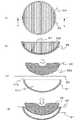
つぎに、本発明の特徴となる第2の偏光板9Lについて図5を用いて説明する。図5は、液晶ライトバルブ2と出射側偏光板8、および第2の偏光板9Lとの関係を示すものである。液晶ライトバルブ2の出射面の中心からの光束は、出射側偏光板8の入射面内においては、その位置に対応した方位角で入射することになる。したがって、出射側偏光板8の入射面内における中心から一定以上の距離の部分では、光学軸(吸収軸)の垂直または水平に対して45度の位置を頂点としてs偏光光の吸収率が低下する部分ができる。図5では、出射側偏光板8で吸収できずに透過した不要光であるs偏光光34、35を第2の偏光板9Lが吸収して、投射光学系10に到達させないことによりコントラストの向上が可能となる様子を示している。図において、液晶ライトバルブ2から出射された光束は、光軸C1を中心に放射状に広がるので角度分布を有しているが、第2の偏光板9Lに入射する角度が垂直となるように液晶ライトバルブ2からの入射面9Lf(厳密には光学軸(吸収軸)が形成されている面)の面形状を決定することにより、コントラスト特性を向上させることが可能となる。ここで、光線33は、液晶ライトバルブ2を出射した光束の主光線を示し、入射角が0度に近いため出射側偏光板8で吸収される。光線34および光線35は、周辺光であり角度を有して液晶ライトバルブ2を出射するため、出射側偏光板8の入射面内において所定の方位角と入射角(極角)を持った光束の一部が透過することになる。しかし、第2の偏光板9Lの入射面9Lfに対して、光線34および光線35が概ね垂直であるため、第2の偏光板9Lへの入射角度が小さくなるので、吸収特性が向上し、結果としてコントラストを向上させることが可能となる。  Next, the secondpolarizing plate 9L, which is a feature of the present invention, will be described with reference to FIG. FIG. 5 shows the relationship between the liquid crystallight valve 2, the exit-sidepolarizing plate 8, and the secondpolarizing plate 9L. The light beam from the center of the exit surface of the liquid crystallight valve 2 is incident on the entrance surface of the exit-sidepolarizing plate 8 at an azimuth angle corresponding to the position. Accordingly, in the portion of the exitplane polarizing plate 8 at a certain distance from the center on the incident surface, the absorption rate of the s-polarized light is lowered with the position at 45 degrees perpendicular to or horizontal to the optical axis (absorption axis). A part to do. In FIG. 5, the second polarizing plate 9 </ b> L absorbs the s-polarizedlight 34 and 35, which are unnecessary light that cannot be absorbed by the output-sidepolarizing plate 8, and does not reach the projectionoptical system 10, thereby improving the contrast. This shows how it becomes possible. In the figure, the light beam emitted from the liquid crystallight valve 2 has an angular distribution because it spreads radially around the optical axis C1, but the liquid crystal so that the angle incident on the secondpolarizing plate 9L is vertical. By determining the surface shape of the incident surface 9Lf from the light valve 2 (strictly speaking, the surface on which the optical axis (absorption axis) is formed), the contrast characteristics can be improved. Here, thelight ray 33 indicates the principal ray of the light beam emitted from the liquid crystallight valve 2 and is absorbed by the emissionside polarizing plate 8 because the incident angle is close to 0 degrees. Since thelight beam 34 and thelight beam 35 are ambient light and exit the liquid crystallight valve 2 at an angle, the light beam has a predetermined azimuth angle and an incident angle (polar angle) within the incident surface of the output-sidepolarizing plate 8. A part of will be transmitted. However, since thelight beam 34 and thelight beam 35 are substantially perpendicular to the incident surface 9Lf of the secondpolarizing plate 9L, the incident angle to the secondpolarizing plate 9L is reduced, and the absorption characteristics are improved. As a result, the contrast can be improved.

一般的に、光源3から液晶ライトバルブ2までの照明光学系は、液晶ライトバルブ2の中心位置が最も光の強度が強い。従って、第2の偏光板9Lの光学軸(吸収軸)が形成されている面の最適な形状(本実施の形態1では実質的に入射面9Lfの面形状)は、図6に示すように液晶ライトバルブ2から第2の偏光板9Lまでの間隔を曲率半径とした球面となる。図6は、液晶ライトバルブ2と出射側偏光板8および第2の偏光板9Lの入射面9Lfのx方向における中心部のyz平面内での断面形状および液晶ライトバルブ2の中心位置からの出射光を示している。図において、出射光を示す矢印41、42、43の距離はそれぞれ等しく、第2の偏光板9Lの入射面9Lfの凹形状の曲率半径となっている。従って、出射光41、42、43は、入射面9Lfに対し垂直に入射することになり、出射側偏光板8と異なり、入射面9Lf内の位置によって入射角や方位角が変化することがなく、安定してs偏光光を吸収することができる。但し、出射側偏光板8を設けた場合、出射側偏光板8の影響で光路長、つまり光学距離が変化するため、液晶ライトバルブ2から第2の偏光板9Lまでの距離をd1、出射側偏光板8の厚みをt1、屈折率をn1とした場合、第2の偏光板9Lの入射面9Lfの曲率半径R1(=光学距離)は式1となる。しかし、一般的に偏光板の厚みは0.5mm程度であり、無視できるレベルである。ただし、照明光学系の出射側偏光板8への入射角度強度特性より、第2の偏光板9Lの入射面9Lfの最適形状(曲率半径)を決定するようにしても構わない。
R1=d1+t1×((1/n1)−1) ・・・式1
In general, the illumination optical system from thelight source 3 to the liquid crystallight valve 2 has the strongest light intensity at the center position of the liquid crystallight valve 2. Therefore, the optimum shape of the surface on which the optical axis (absorption axis) of the secondpolarizing plate 9L is formed (substantially the surface shape of the incident surface 9Lf in the first embodiment) is as shown in FIG. A spherical surface having a curvature radius between the liquid crystallight valve 2 and the secondpolarizing plate 9L. FIG. 6 shows the cross-sectional shape in the yz plane of the central portion in the x direction of the incident surface 9Lf of the liquid crystallight valve 2, the exit-sidepolarizing plate 8 and the secondpolarizing plate 9L, and the exit from the center position of the liquid crystallight valve 2. Shows light. In the figure, the distances ofarrows 41, 42 and 43 indicating the emitted light are equal to each other, which is a concave curvature radius of the incident surface 9Lf of the secondpolarizing plate 9L. Accordingly, theoutgoing lights 41, 42, and 43 are incident on the incident surface 9Lf perpendicularly, and unlike the exit-sidepolarizing plate 8, the incident angle and the azimuth are not changed depending on the position in the incident surface 9Lf. The s-polarized light can be absorbed stably. However, when the exit-sidepolarizing plate 8 is provided, the optical path length, that is, the optical distance changes due to the influence of the exit-sidepolarizing plate 8, so the distance from the liquid crystallight valve 2 to the secondpolarizing plate 9L is d1, the exit side. When the thickness of thepolarizing plate 8 is t1 and the refractive index is n1, the radius of curvature R1 (= optical distance) of the incident surface 9Lf of the secondpolarizing plate 9L is expressed byFormula 1. However, in general, the thickness of the polarizing plate is about 0.5 mm, which is negligible. However, the optimal shape (curvature radius) of the incident surface 9Lf of the secondpolarizing plate 9L may be determined from the incident angle intensity characteristic to the outputside polarizing plate 8 of the illumination optical system.
R1 = d1 + t1 × ((1 / n1) −1)Equation 1

ただし、液晶ライトバルブ2の出射端(面)のサイズおよび液晶ライトバルブ2から第2の偏光板9Lまでの距離d1の関係により、曲率半径R1が小さくなり、式1が構造上成立しない場合が存在する。また、後述するように液晶ライトバルブ2の出射端の周縁部(面内における端部)から出射する光については、式1で得られる曲率半径R1より大きな曲率半径の方が好ましい場合がある。そこで、液晶ライトバルブ2の出射面のサイズを考慮して、液晶ライトバルブ2で変調されなかった光を効率よく吸収できる曲率半径R1の上限範囲を次のようにして算出した。簡単のため、出射側偏光板8を除いた場合を示す。  However, depending on the relationship between the size of the emission end (surface) of the liquid crystallight valve 2 and the distance d1 from the liquid crystallight valve 2 to the secondpolarizing plate 9L, the radius of curvature R1 may be small andEquation 1 may not be structurally established. Exists. Further, as will be described later, with respect to light emitted from the peripheral edge portion (end portion in the plane) of the emission end of the liquid crystallight valve 2, a curvature radius larger than the curvature radius R1 obtained byExpression 1 may be preferable. Therefore, in consideration of the size of the exit surface of the liquid crystallight valve 2, the upper limit range of the radius of curvature R1 that can efficiently absorb light that was not modulated by the liquid crystallight valve 2 was calculated as follows. For simplicity, the case where the outputside polarizing plate 8 is removed is shown.

図7に液晶ライトバルブ2の出射端のサイズおよび液晶ライトバルブ2の光軸C1からx方向に最も離れた位置の光線の軌跡を示す。液晶ライトバルブ2の長軸方向(x方向)の長さをx1、液晶ライトバルブ2の出射端から第2の偏光板9Lまでの距離をd1、液晶ライトバルブ2からの有効発散角(照明光学系のFナンバーにより決定される)をβとする。ここで、矢印44は液晶ライトバルブ2の光軸C1からx方向に最も離れた位置(x軸での周縁部)から出射される主光線を示し、矢印45は有効発散光(周辺光)を示す。図7の場合、矢印45で示される光線が光軸C1から出射したものと仮定すると、仮定した出射源から液晶ライトバルブ2の出射端までの距離d0は式2で表すことができる。したがって、液晶ライトバルブ2の出射端の周縁部からの光線にとって最適な第2の偏光板9Lの入射面9Lfの曲率半径R1xは、式3となる。
d0=(x1/2)/tanβ ・・・式2
R1x=d0+d1 ・・・式3
FIG. 7 shows the size of the emission end of the liquid crystallight valve 2 and the trajectory of the light beam farthest from the optical axis C1 of the liquid crystallight valve 2 in the x direction. The length in the major axis direction (x direction) of the liquid crystallight valve 2 is x1, the distance from the emission end of the liquid crystallight valve 2 to the secondpolarizing plate 9L is d1, and the effective divergence angle from the liquid crystal light valve 2 (illumination optics) Let β be determined by the F number of the system. Here, anarrow 44 indicates a principal ray emitted from a position (peripheral edge in the x axis) farthest in the x direction from the optical axis C1 of the liquid crystallight valve 2, and anarrow 45 indicates effective divergent light (ambient light). Show. In the case of FIG. 7, assuming that the light beam indicated by thearrow 45 is emitted from the optical axis C1, the distance d0 from the assumed emission source to the emission end of the liquid crystallight valve 2 can be expressed byEquation 2. Therefore, the radius of curvature R1x of the incident surface 9Lf of the secondpolarizing plate 9L that is optimal for the light beam from the peripheral edge of the emission end of the liquid crystallight valve 2 is expressed byEquation 3.
d0 = (x1 / 2) /tanβ Equation 2
R1x = d0 +d1 Formula 3

従って、第2の偏光板9Lの入射面9Lfの曲率半径R1を式4の範囲内に設定すれば、液晶ライトバルブ2で変調されなかった光を効率よく吸収する効果が得られる。
d1≦R1≦d1+(x1/2)/tanβ ・・・式4
ただし、上述したように液晶ライトバルブ2の出射端の面内では、中心位置の光が最も光強度が強いので、曲率半径R1は周縁部からの光に適したd1+(x1/2)/tanβよりも中心部からの光に適したd1に近いほうが、吸収率が高くなる傾向にある。
Therefore, if the radius of curvature R1 of the incident surface 9Lf of the secondpolarizing plate 9L is set within the range ofExpression 4, an effect of efficiently absorbing light that has not been modulated by the liquid crystallight valve 2 can be obtained.
d1 ≦ R1 ≦ d1 + (x1 / 2) /tan β Equation 4
However, as described above, in the plane of the emission end of the liquid crystallight valve 2, the light at the center position has the strongest light intensity. Therefore, the curvature radius R1 is d1 + (x1 / 2) / tanβ suitable for light from the peripheral portion. The absorption rate tends to be higher near d1 suitable for light from the center than.

また式4では、簡単のため出射側偏光板8については考慮していないが、出射側偏光板8の厚み及び屈折率を考慮した場合、式4の左辺と右辺にt1×((1/n1)−1)を加えることとなる。  InExpression 4, the outputside polarizing plate 8 is not considered for the sake of simplicity. However, when the thickness and refractive index of the outputside polarizing plate 8 are taken into consideration, t1 × ((1 / n1) ) -1) will be added.

なお、本実施の形態1においては、第2の偏光板9Lの凹レンズに偏光フィルムを貼付することで形成したため、投射光学系10の結像性能に影響を及ぼす、つまり、偏光光学系も投射光学系の機能の一部を担うことになる。そのため、上述した入射面9Lfの曲率半径を有する第2の偏光板9Lの光学特性を考慮に入れて、投射光学系10を設計する必要がある。また、第2の偏光板9Sとして薄い凹面形状の透過板を用いてもよいが、その場合でも光学特性に影響を及ぼすので、第2の偏光板9Sの光学特性を考慮に入れて、投射光学系10を設計する必要がある。  In the first embodiment, since the polarizing film is formed on the concave lens of the secondpolarizing plate 9L, the imaging performance of the projectionoptical system 10 is affected. That is, the polarization optical system is also a projection optical system. It will be responsible for some of the functions of the system. Therefore, it is necessary to design the projectionoptical system 10 in consideration of the optical characteristics of the secondpolarizing plate 9L having the radius of curvature of the incident surface 9Lf described above. In addition, a thin concave transmission plate may be used as the second polarizing plate 9S. However, even in that case, it affects the optical characteristics. Therefore, the optical characteristics of the second polarizing plate 9S are taken into consideration and the projection optics is used.System 10 needs to be designed.

ここで、偏光機能を有する部分が凹面形状の第2の偏光板9Lまたは9Sの構成及び製造方法について説明する。図8は第2の偏光板9Sの構成及び製造方法を示したもので、図8(a)は第2の偏光板9Sの平面図(z方向で見た場合)、図8(b)は図8(a)のb−b線における切断断面図であり、図8(c)、図8(d)は製造工程中の切断断面図を示す。図8(a)、(b)において、第2の偏光板9Sの入射面9Sfは、液晶ライトバルブ2の中心からの距離を曲率半径R1とする球面をなし、その表面には一方向に光学軸(吸収軸)を有する偏光フィルムが貼付されており、入射面9Sfには地球儀の緯線のように光学軸(吸収軸)が並んでいる。  Here, the configuration and manufacturing method of the secondpolarizing plate 9L or 9S having a concave portion in the polarization function will be described. FIG. 8 shows the configuration and the manufacturing method of the second polarizing plate 9S. FIG. 8A is a plan view of the second polarizing plate 9S (when viewed in the z direction), and FIG. FIG. 8C is a cross-sectional view taken along line bb in FIG. 8A, and FIGS. 8C and 8D are cross-sectional views taken during the manufacturing process. 8A and 8B, the incident surface 9Sf of the second polarizing plate 9S has a spherical surface with a radius of curvature R1 from the center of the liquid crystallight valve 2, and the surface is optically unidirectional. A polarizing film having an axis (absorption axis) is affixed, and an optical axis (absorption axis) is arranged on the incident surface 9Sf like a parallel line of the globe.

つぎに、製造方法について説明する。図8(c)に示すように透明材料からなり、表面91sが半径R1(厳密には偏光フィルム90の厚みを除いた値)の球面(凹面形状)で厚みが一定の透過板91に偏光フィルム90を貼付する。はじめに透過板91のエッジ部91e部分に偏光フィルム90を密着させた状態で、表面91sに対応した表面92sが凸形状の型92を押し当てる。すると、図8(d)に示すように偏光フィルム90のうち、エッジ部91eより内側の部分は型92の表面92sの形に沿って引き延ばされながら透過板91の表面91sに押し付けられ、熱処理を施すことにより透過板91と密着する。型92をはずした後、偏光フィルム90のエッジ部91eより外側の部分を切り取れば、図8(a)、(b)に示す第2の偏光板9Sが完成する。なお、透過板91の表面91sと偏光フィルム90の密着性を向上させるために真空中で貼付するようにしてもよい。この場合、型92の代わりに空気圧等により偏光フィルム90を透過板91の表面91sに押し付けるようにすれば、偏光フィルム90をより均等に引き延ばすことができる。なお、ここでは、透過板91を用いた場合について説明したが、凹レンズを用いた場合にも同様に製造することができる。  Next, a manufacturing method will be described. As shown in FIG. 8C, the polarizing film is formed on thetransmission plate 91 made of a transparent material, having a spherical surface (concave surface shape) having a radius R1 (strictly excluding the thickness of the polarizing film 90) and a constant thickness. 90 is affixed. First, in a state where thepolarizing film 90 is in close contact with theedge portion 91e portion of thetransmission plate 91, thesurface 92s corresponding to thesurface 91s presses theconvex mold 92. Then, as shown in FIG.8 (d), the part inside theedge part 91e among the polarizingfilms 90 is pressed along thesurface 91s of thetransmission board 91, being extended along the shape of thesurface 92s of the type |mold 92, It adheres to thetransmission plate 91 by heat treatment. After removing themold 92, if the portion outside theedge portion 91e of thepolarizing film 90 is cut off, the second polarizing plate 9S shown in FIGS. 8A and 8B is completed. In addition, you may make it stick in a vacuum in order to improve the adhesiveness of thesurface 91s of thetransmissive plate 91, and thepolarizing film 90. FIG. In this case, if thepolarizing film 90 is pressed against thesurface 91s of thetransmission plate 91 by air pressure or the like instead of themold 92, thepolarizing film 90 can be stretched more evenly. Although the case where thetransmission plate 91 is used has been described here, the same manufacturing can be performed when a concave lens is used.

以上のように、本実施の形態1にかかる偏光光学系によれば、液晶ライトバルブ2の入射側に設置され、照明光学系(4、5a、5b)から液晶ライトバルブ2に照射される光のうち、第1の直線偏光光(s偏光光)を透過する第1の偏光板7と、液晶ライトバルブ2の出射側に設置され、液晶ライトバルブ2から投射光学系10に出力される映像光のうち、第1の直線偏光光(s偏光光)と異なる第2の直線偏光光(p偏光光)を透過する第2の偏光板9L(または9S)とを備え、第2の偏光板(9Lまたは9S)は、液晶ライトバルブ2に対して入射面(9Lfまたは9Sf)が凹面形状をなすように構成したので、液晶ライトバルブ2から角度を持って出力された光は凹面形状の入射面(9Lfまたは9Sf)となす角度が小さくなり、液晶ライトバルブ2で変調されなかった光を効率よく吸収することができ、コントラストが向上する。  As described above, according to the polarization optical system according to the first embodiment, the light that is installed on the incident side of the liquid crystallight valve 2 and is applied to the liquid crystallight valve 2 from the illumination optical system (4, 5a, 5b). Among them, the firstpolarizing plate 7 that transmits the first linearly polarized light (s-polarized light) and the image that is installed on the emission side of the liquid crystallight valve 2 and is output from the liquid crystallight valve 2 to the projectionoptical system 10. A secondpolarizing plate 9L (or 9S) that transmits a second linearly polarized light (p-polarized light) different from the first linearly polarized light (s-polarized light) out of the light, and the second polarizing plate (9L or 9S) is configured such that the incident surface (9Lf or 9Sf) has a concave shape with respect to the liquid crystallight valve 2, so that the light output from the liquid crystallight valve 2 with an angle is incident on the concave surface. The angle formed with the surface (9Lf or 9Sf) is small The light that is not modulated by the liquid crystallight valve 2 can be absorbed efficiently, thereby improving the contrast.

とくに、第2の偏光板(9Lまたは9S)の入射面(9Lfまたは9Sf)の凹面形状は、液晶ライトバルブ2から第2の偏光板(9Lまたは9S)との光学距離(式1のR1)を半径とする球面になるように構成したので、液晶ライトバルブ2の中心から出射した光は入射面(9Lfまたは9Sf)のどの位置においても垂直に入射するので、液晶ライトバルブ2で変調されなかった光を効率よく吸収することができ、コントラストが向上する。In particular, the concave shape of the incident surface (9Lf or 9Sf) of the second polarizing plate (9L or 9S) is the optical distance from the liquid crystallight valve 2 to the second polarizing plate (9L or 9S) (R1 in Formula 1). Since the light is emitted from the center of the liquid crystallight valve 2 at any position on the incident surface (9Lf or 9Sf), the light is not modulated by the liquid crystallight valve 2. Light can be absorbed efficiently, and the contrast is improved.

あるいは、液晶ライトバルブ2の出射端の長軸方向(x方向)の長さをx1、液晶ライトバルブ2の出射端から第2の偏光板9Lまでの距離をd1、液晶ライトバルブ2からの有効発散角をβとし、第2の偏光板9Lの入射面9Lfの曲率半径R1を式4の範囲内に設定するように構成すれば、液晶ライトバルブ2で変調されなかった光を効率よく吸収する効果が得られる。
d1≦R1≦d1+(x1/2)/tanβ ・・・式4
Alternatively, the length in the major axis direction (x direction) of the exit end of the liquid crystallight valve 2 is x1, the distance from the exit end of the liquid crystallight valve 2 to the secondpolarizing plate 9L is d1, and the effective distance from the liquid crystallight valve 2 If the divergence angle is β and the radius of curvature R1 of the incident surface 9Lf of the secondpolarizing plate 9L is set within the range ofEquation 4, the light that is not modulated by the liquid crystallight valve 2 is efficiently absorbed. An effect is obtained.
d1 ≦ R1 ≦ d1 + (x1 / 2) /tan β Equation 4

また、第2の偏光板9Sまたは9Lは、凹面形状を有する透過板91または凹レンズの表面91sに偏光フィルム90を貼付して構成したので、容易に製作することができる。  Further, since the secondpolarizing plate 9S or 9L is configured by attaching thepolarizing film 90 to thetransmission plate 91 having a concave shape or thesurface 91s of the concave lens, it can be easily manufactured.

さらに、液晶ライトバルブ2と第2の偏光板(9Lまたは9S)との間には、第1の偏光光(s偏光光)と異なる第2の偏光光(p偏光光)を透過し、入射面が平坦な出射側偏光板8を備えるように構成したので、さらに効率的に液晶ライトバルブ2で変調されなかった光を効率よく吸収することができ、コントラストが向上する。  Further, between the liquid crystallight valve 2 and the second polarizing plate (9L or 9S), the second polarized light (p-polarized light) different from the first polarized light (s-polarized light) is transmitted and incident. Since the light-emitting sidepolarizing plate 8 having a flat surface is provided, the light that is not modulated by the liquid crystallight valve 2 can be efficiently absorbed, and the contrast is improved.

とくに、第2の直線偏光光(p偏光光)は、第1の直線偏光光(s偏光光)に対して偏光軸が90度異なるようにしたので、液晶ライトバルブ2で変調されなかった光を確実に吸収することができ、コントラストが向上する。  In particular, the second linearly polarized light (p-polarized light) has a polarization axis different from that of the first linearly polarized light (s-polarized light) by 90 degrees. Can be reliably absorbed, and the contrast is improved.

また、第1の偏光板7と液晶ライトバルブ2との間、または、液晶ライトバルブ2と第2の偏光板8との間には、液晶ライトバルブ2により発生する偏光光の位相差を補償する光学補償板を備えることにより、よりコントラストを向上させることができる。  Further, a phase difference of polarized light generated by the liquid crystallight valve 2 is compensated between the firstpolarizing plate 7 and the liquid crystallight valve 2 or between the liquid crystallight valve 2 and the secondpolarizing plate 8. By providing the optical compensator that performs the contrast, the contrast can be further improved.

また、本実施の形態1にかかる投射型液晶表示装置によれば、液晶ライトバルブ2と、液晶ライトバルブ2に照射させるための光線を発する光源3と、光源3から発せられた光線を液晶ライトバルブ2に照射する照明光学系(4、5a、5b)と、液晶ライトバルブ2から出力された映像光をスクリーンに投射する投射光学系10と、液晶ライトバルブ2の入射側に配置された第1の偏光板7と、液晶ライトバルブ2の出射側に配置された第2の偏光板(9Lまたは9S)とを有する上記偏光光学系と、を備えたので、コントラストの高い映像を表示することができる。  Further, according to the projection type liquid crystal display device according to the first embodiment, the liquid crystallight valve 2, thelight source 3 that emits light for irradiating the liquid crystallight valve 2, and the light emitted from thelight source 3 The illumination optical system (4, 5a, 5b) for irradiating thebulb 2, the projectionoptical system 10 for projecting the image light output from the liquid crystallight valve 2 onto the screen, and the first arranged on the incident side of the liquid crystallight valve 2 Since the polarizing optical system having thepolarizing plate 7 and the second polarizing plate (9L or 9S) disposed on the emission side of the liquid crystallight valve 2 is provided, an image with high contrast is displayed. Can do.

なお、本実施の形態1においては、第2の偏光板9Sまたは9Lの入射側の面に、光学軸(吸収軸)を有する凹面形状の入射面9Sfまたは9Lfを形成したが、凸面形状(液晶ライトバルブ2から出射面までの光学距離を半径とする球面)の出射側に偏光フィルム90を貼付して、偏光機能を有する凹面形状の入射面を出射側の面に形成するようにしてもよい。また、液晶ライトバルブ2の入射側に設けた第1の偏光板7における出射側の面を凹面形状に、あるいは入射側の面を凸面形状としてもよく、その場合も球面の半径は液晶ライトバルブ2の入射面までの光学距離を半径とすればよい。  In the first embodiment, the concave incident surface 9Sf or 9Lf having the optical axis (absorption axis) is formed on the incident-side surface of the secondpolarizing plate 9S or 9L. Apolarizing film 90 may be affixed to the exit side of a spherical surface having a radius of the optical distance from thelight valve 2 to the exit surface, and a concave entrance surface having a polarization function may be formed on the exit side surface. . In addition, the exit side surface of the firstpolarizing plate 7 provided on the incident side of the liquid crystallight valve 2 may be a concave surface, or the incident side surface may be a convex surface. The optical distance to the second incident surface may be a radius.

実施の形態2.
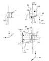
図9は、本実施の形態2に係る偏光光学系およびその偏光光学系を用いた投射型液晶表示装置の構成図である。図において、投射型液晶表示装置101は、反射型液晶ライトバルブ102と、反射型液晶ライトバルブ102に光を照射するための光源3と、光源3から反射型液晶ライトバルブ102に至る光路上に配置された集光レンズ群105と、集光レンズ群105の後段に配置された柱状光学素子104と、柱状光学素子104の後段に配置された4枚構成のリレーレンズ群6a〜6dとを備えている。そして、偏光光学系は、リレーレンズ6cと投射光学系10との間に配置され、反射型液晶ライトバルブ102に照射される光のうち、特定の直線偏光光(例えば、p偏光光)を透過する平板状の入射側偏光板(第1の偏光板107)と、第1の偏光板107と反射型液晶ライトバルブ102との間に光軸C1に対して45度の傾きで配置され、p偏光光を透過し、反射型ライトバルブ102から出力された映像光を光軸C1に対して垂直方向の光軸C2に向けて反射する反射型偏光板11と、光軸C2上で反射型偏光板11の後段に配置され、反射型液晶ライトバルブ102から出射された光のうち第1の偏光板107の光学軸(吸収軸)と偏光軸が平行な直線偏光光(s偏光光)を透過する出射側偏光板108と、入射面109Lfが凹面形状(反射型液晶ライトバルブ102の出射端を中心とし、光学距離を半径とする球面に相当)をなし、第1の偏光板107の光学軸(吸収軸)と偏光軸が平行な直線偏光光(s偏光光)を透過する偏光フィルム付レンズ(第2の偏光板109L)を有する。
尚、本実施の形態2においても、実施の形態1と同様に、投射型液晶表示装置101は、第2の偏光板109Lの後段に配置される投射光学系10と、投射光学系10の後段に配置されるスクリーン(図示せず)とを更に備える。また、図9には、1色の光の光路に関する構成を示しているが、赤、緑、青の各色について投射光学系10以外の各構成を備え、光合成素子(図示せず)によって各色の画像光を合成してから投射光学系10によってスクリーンに投射させるようにしてもよい。
Embodiment 2. FIG.
FIG. 9 is a configuration diagram of a polarizing optical system according to the second embodiment and a projection type liquid crystal display device using the polarizing optical system. In the figure, a projection type liquidcrystal display device 101 includes a reflection type liquid crystallight valve 102, alight source 3 for irradiating light to the reflection type liquid crystallight valve 102, and an optical path from thelight source 3 to the reflection type liquid crystallight valve 102. A condensinglens group 105 disposed; a columnaroptical element 104 disposed downstream of the condensinglens group 105; and fourrelay lens groups 6a to 6d disposed downstream of the columnaroptical element 104. ing. The polarization optical system is disposed between therelay lens 6c and the projectionoptical system 10, and transmits specific linearly polarized light (for example, p-polarized light) out of the light emitted to the reflective liquid crystallight valve 102. Between the firstpolarizing plate 107 and the reflective liquid crystallight valve 102 with a 45 degree inclination with respect to the optical axis C1 and p A reflectivepolarizing plate 11 that transmits polarized light and reflects image light output from thereflective light valve 102 toward an optical axis C2 perpendicular to the optical axis C1, and a reflective polarized light on the optical axis C2. Of the light emitted from the reflective liquid crystallight valve 102, disposed behind theplate 11, it transmits linearly polarized light (s-polarized light) in which the optical axis (absorption axis) of the firstpolarizing plate 107 and the polarization axis are parallel. The exitside polarizing plate 108 and the incident surface 109Lf are concave. Linearly polarized light having a shape (corresponding to a spherical surface centered on the output end of the reflective liquid crystallight valve 102 and having an optical distance as a radius) and having the optical axis (absorption axis) of the firstpolarizing plate 107 and the polarization axis parallel to each other A lens with a polarizing film (secondpolarizing plate 109L) that transmits (s-polarized light) is included.
Also in the second embodiment, as in the first embodiment, the projection type liquidcrystal display device 101 includes a projectionoptical system 10 disposed at the rear stage of the secondpolarizing plate 109L and a rear stage of the projectionoptical system 10. And a screen (not shown). FIG. 9 shows a configuration related to the optical path of light of one color. However, each color of red, green, and blue is provided with a configuration other than the projectionoptical system 10, and each color is changed by a light combining element (not shown). The image light may be combined and then projected onto the screen by the projectionoptical system 10.

つぎに、各構成について説明する。なお、第1の実施の形態と共通する部分については説明を省略する。
光源3は、ここでは固体光源の一つであるLEDを一例として挙げているが、高圧水銀ランプ、キセノンランプ、無電極放電ランプおよびレーザでも構わない。ただし、光源3から出射される光を柱状光学素子104に集光する必要がある。
Next, each configuration will be described. Note that description of portions common to the first embodiment is omitted.
Here, thelight source 3 is an LED, which is one of solid light sources, but may be a high-pressure mercury lamp, a xenon lamp, an electrodeless discharge lamp, or a laser. However, it is necessary to collect the light emitted from thelight source 3 on the columnaroptical element 104.

集光レンズ群105は、ここでは4枚構成としているが、柱状光学素子104に集光できるのであれば何枚構成でも構わない。ただし、LEDのような光の発散角が大きい光源を用いる場合は、1枚目を非球面レンズとすることにより、柱状光学素子104への集光効率を向上させることが可能となる。また、非球面レンズを用いる場合は、光源3から発せられる熱の影響を考慮し、ガラスを用いることが好ましい。プラスチックレンズを用いた場合は、レンズの界面反射を低減するマルチコーティングの剥れが熱により生じるおそれがあるからである。  The condensinglens group 105 has a four-lens configuration here, but may have any number of configurations as long as the condensinglens group 105 can condense on the columnaroptical element 104. However, when a light source having a large light divergence angle, such as an LED, is used, the light collection efficiency to the columnaroptical element 104 can be improved by using the first aspherical lens. When an aspheric lens is used, it is preferable to use glass in consideration of the influence of heat generated from thelight source 3. This is because when a plastic lens is used, peeling of the multi-coating that reduces interface reflection of the lens may occur due to heat.

柱状光学素子104は、集光レンズ群105を通過した光の、光断面内(すなわち、光軸C1上を進む中心光に垂直な平面内)における光強度分布を均一化する(すなわち、照度むらを低減する)機能を有する。柱状光学素子104としては、一般的にガラス又は樹脂等の透明材料で作られ、側壁内側が全反射面となるように構成された例えば、四角柱状のロッド(すなわち、断面形状が四辺形の柱状部材)、又は、光反射面を内側にして筒状に組み合わされ、断面形状が四辺形のパイプ(管状部材)がある。柱状光学素子104が四角柱状ロッドである場合には、透明材料と空気界面との全反射作用を利用して光を複数回反射させた後に出射端(出射口)から出射させる。柱状光学素子104が四辺形のパイプである場合には、内側を向く表面鏡の反射作用を利用して光を複数回反射させた後に、出射口から出射させる。柱状光学素子104は、光の進行方向に適当な長さを確保すれば、内側で複数回反射した光が柱状光学素子104の出射端の近傍に重畳照射され、柱状光学素子104の出射端近傍においては、略均一な強度分布が得られる。この略均一な強度分布を有する出射端を、リレーレンズ群6a〜dによって反射型液晶ライトバルブ102へと導く。  The columnaroptical element 104 uniformizes the light intensity distribution of the light that has passed through thecondenser lens group 105 in the light section (that is, in a plane perpendicular to the central light traveling on the optical axis C1) (that is, uneven illuminance). Function). The columnaroptical element 104 is generally made of a transparent material such as glass or resin, and is configured to have a total reflection surface on the inner side wall, for example, a square columnar rod (that is, a columnar column having a quadrangular cross section) Member), or a pipe (tubular member) having a cross-sectional shape of a quadrilateral that is combined in a cylindrical shape with the light reflecting surface on the inside. When the columnaroptical element 104 is a quadrangular columnar rod, light is reflected multiple times using the total reflection action between the transparent material and the air interface, and then emitted from the emission end (emission port). When the columnaroptical element 104 is a quadrilateral pipe, the light is reflected multiple times using the reflecting action of the surface mirror facing inward and then emitted from the exit. If the columnaroptical element 104 has an appropriate length in the light traveling direction, the light reflected a plurality of times inside is superimposed and irradiated near the exit end of the columnaroptical element 104, and near the exit end of the columnaroptical element 104. In, a substantially uniform intensity distribution is obtained. The emission end having the substantially uniform intensity distribution is guided to the reflective liquid crystallight valve 102 by therelay lens groups 6a to 6d.

リレーレンズ群6a〜dは、4枚構成からなっているが、反射型液晶ライトバルブ102に入射する主光線が光軸C1と略並行光となればよく、3枚構成でも構わない。つまり、照明光学系(柱状光学素子104と、集光レンズ群105と、リレーレンズ群6a〜6d)をテレセントリック光学系とすればよい。また、リレーレンズ6cと6dの間に第1の偏光板107を有するが、第1の偏光板107も入射角度依存性があるため、できる限りリレーレンズ群6a〜d内において略並行光成分が多い位置に配置することが好ましい。  Although therelay lens groups 6a to 6d have a four-lens configuration, it is sufficient that the chief ray incident on the reflective liquid crystallight valve 102 is substantially parallel to the optical axis C1, and may be a three-lens configuration. That is, the illumination optical system (the columnaroptical element 104, the condensinglens group 105, and therelay lens groups 6a to 6d) may be a telecentric optical system. Further, the firstpolarizing plate 107 is provided between therelay lenses 6c and 6d. However, since the firstpolarizing plate 107 also has an incident angle dependency, a substantially parallel light component is present in therelay lens groups 6a to 6d as much as possible. It is preferable to arrange in many positions.

反射型液晶ライトバルブ102は、投射する画像光の各画素に対応する液晶表示素子を多数(例えば、数十万個)平面的に配列したものであり、画素情報に応じて各液晶表示素子を動作させることで、入射された光を基に画像光を出射する。  The reflective liquid crystallight valve 102 has a large number (for example, hundreds of thousands) of liquid crystal display elements corresponding to each pixel of image light to be projected arranged in a plane, and each liquid crystal display element is arranged according to pixel information. By operating, image light is emitted based on the incident light.

つぎに、偏光光学系について説明する。
図10は、第1の偏光板107、反射型偏光板11、反射型液晶ライトバルブ102、出射側偏光板108の作用を説明する図である。ここでは、第1の偏光板107の前段、および出射側偏光板108の後段は便宜上省略している。図10(a)に第1の偏光板107にランダム偏光光が入射する場合、投射光学系10に光束が到達する場合の光線の軌跡60と、到達しない場合の光線の軌跡61を示す。図10(b)に第1の偏光板107の光学軸(吸収軸)、図10(c)に出射側偏光板108の光学軸(吸収軸)の一例(矢印が光学軸を示す。)を示す。第1の偏光板107がp偏光光を透過する場合、反射型液晶ライトバルブ102にはp偏光光が到達する。到達したp偏光光のうち、反射型液晶ライトバルブ102内で偏光軸が回転されて出力された光60(s偏光光であって有効な映像光となるもの)は、反射型偏光板11で反射され、光軸C1に対して垂直な光軸C2に沿って(図中下向き)進み、s偏光光を透過する出射側偏光板108を透過して投射光学系10に向けて出力される。一方、反射型液晶ライトバルブ102内で偏光軸が回転されずに出力された光61(p偏光光であって不要光となるもの)は、反射型偏光板11を透過する。しかし、図示していないが、反射型偏光板11でも一部のp偏光光を反射してしまうので、不要光61の一部は出射側偏光板108に到達する。
Next, the polarization optical system will be described.
FIG. 10 is a diagram for explaining the operation of the firstpolarizing plate 107, the reflectivepolarizing plate 11, the reflective liquid crystallight valve 102, and the emissionside polarizing plate 108. Here, the previous stage of the firstpolarizing plate 107 and the subsequent stage of the emissionside polarizing plate 108 are omitted for convenience. FIG. 10A shows aray trajectory 60 when the light beam reaches the projectionoptical system 10 when random polarized light is incident on the firstpolarizing plate 107 and aray trajectory 61 when the light beam does not reach the projectionoptical system 10. FIG. 10B shows an example of the optical axis (absorption axis) of the firstpolarizing plate 107, and FIG. 10C shows an example of the optical axis (absorption axis) of the output side polarizing plate 108 (the arrow indicates the optical axis). Show. When the firstpolarizing plate 107 transmits p-polarized light, the p-polarized light reaches the reflective liquid crystallight valve 102. Of the reached p-polarized light, the light 60 (s-polarized light that becomes effective image light) output by rotating the polarization axis in the reflective liquid crystallight valve 102 is reflected by thereflective polarizer 11. The light is reflected, travels along the optical axis C2 perpendicular to the optical axis C1 (downward in the figure), passes through the output-sidepolarizing plate 108 that transmits s-polarized light, and is output toward the projectionoptical system 10. On the other hand, the light 61 (the p-polarized light that becomes unnecessary light) output without rotating the polarization axis in the reflective liquid crystallight valve 102 passes through the reflectivepolarizing plate 11. However, although not shown, part of the p-polarized light is also reflected by the reflectivepolarizing plate 11, so that a part of theunnecessary light 61 reaches the output-sidepolarizing plate 108.

出射側偏光板108を通過する光も実施の形態1と同様に角度分布がついているので、本実施の形態2においても一部の不要光は実施の形態1における図4と同様に、出射側偏光板108を透過することになる。しかし、本実施の形態2では、図9に示すように、出射側偏光板108の後段に第2の偏光板109Lを配置することにより、コントラストを向上させることが可能となる。その動作原理は、実施の形態1で述べたとおりである。  Since the light passing through the outputside polarizing plate 108 has an angular distribution as in the first embodiment, some unnecessary light in the second embodiment is also emitted from the output side as in FIG. 4 in the first embodiment. The light passes through thepolarizing plate 108. However, in the second embodiment, as shown in FIG. 9, the contrast can be improved by disposing the second polarizing plate 109 </ b> L after the emission-sidepolarizing plate 108. The operation principle is as described in the first embodiment.

図11に第2の偏光板109Lの作用を説明する図を示す。ここで、反射型偏光板11より前段および第2の偏光板109Lより後段は便宜上省略した。実施の形態1と同様に、反射型液晶ライトバルブ102から出射された光束は、角度を有しているため、入射面109Lfに入射する角度が垂直となるようにレンズ形状を決定することにより、コントラスト特性を向上させることが可能となる。ここで、光線70は反射型液晶ライトバルブ102を出射した光束の主光線を示し、出射側偏光板108に吸収される。光線71は周辺光であり角度を有して反射型液晶ライトバルブ102を出射するため、出射側偏光板108にて一部透過し、第2の偏光板109Lにて吸収されることとなる。第2の偏光板109Lの入射面109Lfに対して、光線71が概ね垂直であるため、偏光板を平板と見立てた場合の入射角度依存性が小さく吸収特性がよいため、結果としてコントラストを向上させることが可能となる。ここで、第1の偏光板107と出射側偏光板108、および第2の偏光板109Lの光学軸(吸収軸)は実施の形態1と90度異なるが、吸収率に関する特性は実施の形態1と同様と考えて構わないため、実施の形態1と同様の考え方が適用できる。  FIG. 11 is a diagram illustrating the operation of the secondpolarizing plate 109L. Here, the stage before the reflectivepolarizing plate 11 and the stage after the secondpolarizing plate 109L are omitted for convenience. As in the first embodiment, since the light beam emitted from the reflective liquid crystallight valve 102 has an angle, by determining the lens shape so that the angle incident on the incident surface 109Lf is vertical, Contrast characteristics can be improved. Here, the light beam 70 represents the principal light beam emitted from the reflective liquid crystallight valve 102 and is absorbed by the output-sidepolarizing plate 108. Thelight beam 71 is ambient light and has an angle, and is emitted from the reflective liquid crystallight valve 102. Therefore, thelight beam 71 is partially transmitted by the output-sidepolarizing plate 108 and absorbed by the secondpolarizing plate 109L. Since thelight beam 71 is substantially perpendicular to the incident surface 109Lf of the secondpolarizing plate 109L, the incident angle dependency when the polarizing plate is regarded as a flat plate is small, and the absorption characteristics are good, and as a result, the contrast is improved. It becomes possible. Here, the optical axes (absorption axes) of the firstpolarizing plate 107, the emission-sidepolarizing plate 108, and the secondpolarizing plate 109L are 90 degrees different from those of the first embodiment, but the characteristics relating to the absorptance are the first embodiment. Therefore, the same idea as in the first embodiment can be applied.

また、本実施の形態2のように反射型ライトバルブ102を用いる場合でも、反射型液晶ライトバルブ102の中心位置が最も光の強度が強い。従って、第2の偏光板109Lの入射面109Lfとしての最適な形状は、図12に示すように、反射型液晶ライトバルブ102から第2の偏光板109Lまでの光学距離を曲率半径とした場合となる。図12は、反射型液晶ライトバルブ102と出射側偏光板108および反射型偏光板11、第2の偏光板109Lの入射面109Lfを示している。また、反射型液晶ライトバルブ102の中心位置から出射される映像光を示す矢印81、82、83の距離はそれぞれ等しく、第2の偏光板109Lの入射面109Lfの曲率半径となっている。従って、矢印81、82、83は、第2の偏光板109Lの入射位置における入射面109Lfに対し垂直に入射し、入射面109Lf内のどの位置においても入射角がほぼ0度になる。但し、出射側偏光板108により実際の距離と光学距離(光路長)は異なるため、反射型液晶ライトバルブ102から反射型偏光板11までの距離をd3、反射型偏光板11から第2の偏光板109Lまでの距離をd4、出射側偏光板108の厚みをt2、屈折率をn2とした場合、第2の偏光板109Lの入射面109Lfの曲率半径R2は式5となる。しかし、一般的に偏光板の厚みは0.5mm程度であり、無視できるレベルである。また、照明光学系の出射側偏光板108への入射角度強度特性より、第2の偏光板109Lの曲率の最適形状を決定しても構わない。
R2=d3+d4+t2×((1/n2)−1) ・・・式5
Even when thereflective light valve 102 is used as in the second embodiment, the central position of the reflective liquid crystallight valve 102 has the highest light intensity. Therefore, the optimum shape as the incident surface 109Lf of the secondpolarizing plate 109L is that the optical distance from the reflective liquid crystallight valve 102 to the secondpolarizing plate 109L is a radius of curvature, as shown in FIG. Become. FIG. 12 shows the incident surface 109Lf of the reflective liquid crystallight valve 102, the output-sidepolarizing plate 108, the reflectivepolarizing plate 11, and the secondpolarizing plate 109L. Further, the distances of thearrows 81, 82, and 83 indicating the image light emitted from the center position of the reflective liquid crystallight valve 102 are equal to each other, which is the radius of curvature of the incident surface 109Lf of the secondpolarizing plate 109L. Therefore, thearrows 81, 82, and 83 are incident perpendicular to the incident surface 109Lf at the incident position of the secondpolarizing plate 109L, and the incident angle becomes almost 0 degrees at any position within the incident surface 109Lf. However, since the actual distance and the optical distance (optical path length) differ depending on the exitside polarizing plate 108, the distance from the reflective liquid crystallight valve 102 to the reflectivepolarizing plate 11 is d3, and the second polarizing light is reflected from the reflectivepolarizing plate 11 to the second polarized light. When the distance to theplate 109L is d4, the thickness of the exit-sidepolarizing plate 108 is t2, and the refractive index is n2, the radius of curvature R2 of the incident surface 109Lf of the secondpolarizing plate 109L is expressed byEquation 5. However, in general, the thickness of the polarizing plate is about 0.5 mm, which is negligible. Further, the optimum shape of the curvature of the second polarizing plate 109 </ b> L may be determined based on the incident angle intensity characteristic to the outputside polarizing plate 108 of the illumination optical system.
R2 = d3 + d4 + t2 × ((1 / n2) −1)Equation 5

ここでも、実施の形態1と同様に反射型液晶ライトバルブ102の出射端のサイズおよび反射型偏光板11から第2の偏光板109Lまでの距離d4の関係により、曲率半径R2が小さくなり、式5が構造上成立しない場合が存在する。また、周縁部(面内における端部)から出射する光についても、実施の形態1と同様に、式5で得られる曲率半径R2より大きな曲率半径の方が好ましい場合がある。そこで、本実施の形態2においても、反射型液晶ライトバルブ102の出射面のサイズを考慮して、反射型液晶ライトバルブ102で変調されなかった光を効率よく吸収できる曲率半径R2の範囲を算出した。ただし、構成として、y方向が反射型ライトバルブ102の長軸となる点が異なる。  Here, as in the first embodiment, the radius of curvature R2 is reduced due to the relationship between the size of the emission end of the reflective liquid crystallight valve 102 and the distance d4 from the reflectivepolarizing plate 11 to the secondpolarizing plate 109L. There is a case where 5 does not hold due to the structure. Also, for the light emitted from the peripheral edge (the end in the plane), a curvature radius larger than the curvature radius R2 obtained byExpression 5 may be preferable as in the first embodiment. Therefore, also in the second embodiment, in consideration of the size of the exit surface of the reflective liquid crystallight valve 102, the range of the radius of curvature R2 that can efficiently absorb light that has not been modulated by the reflective liquid crystallight valve 102 is calculated. did. However, the difference is that the y-direction is the major axis of thereflective light valve 102.

図13に反射型液晶ライトバルブ102の出射端のサイズおよび反射型液晶ライトバルブ102の光軸C1からy方向に最も離れた位置の光線の軌跡を示す。反射型液晶ライトバルブ102の長軸(y方向)の長さをy1、反射型液晶ライトバルブ102から反射型偏光板11までの距離をd3、反射型偏光板11から第2の偏光板109Lまでの距離をd4、反射型液晶ライトバルブ102からの有効発散角をγとする。ここで、矢印84は反射型液晶ライトバルブ102の光軸C1からy方向に最も離れた位置から出射される主光線を示し、矢印85は有効発散光(周辺光)を示す。図13の場合、反射型偏光板11で折れ曲がった光軸C1、C2を一本の光軸と仮定し、矢印85で示される光線が光軸C1から出射したものと仮定すると、仮定した出射源から反射型液晶ライトバルブ102の出射端までの距離d5は式6で表すことができる。したがって、反射型液晶ライトバルブ102の出射端の周縁部からの光線にとって最適な第2の偏光板109Lの入射面109Lfの曲率半径R2xは、式7となる。
d5=(y1/2)/tanγ ・・・式6
R2x=d5+d3+d4 ・・・式7
FIG. 13 shows the size of the exit end of the reflective liquid crystallight valve 102 and the locus of the light beam farthest from the optical axis C1 of the reflective liquid crystallight valve 102 in the y direction. The length of the major axis (y direction) of the reflective liquid crystallight valve 102 is y1, the distance from the reflective liquid crystallight valve 102 to thereflective polarizer 11 is d3, and from thereflective polarizer 11 to thesecond polarizer 109L. Is d4, and the effective divergence angle from the reflective liquid crystallight valve 102 is γ. Here, anarrow 84 indicates a principal ray emitted from a position farthest in the y direction from the optical axis C1 of the reflective liquid crystallight valve 102, and anarrow 85 indicates effective divergent light (ambient light). In the case of FIG. 13, it is assumed that the optical axes C1 and C2 bent by the reflectivepolarizing plate 11 are one optical axis, and that the light beam indicated by thearrow 85 is emitted from the optical axis C1. The distance d5 from the output end of the reflective liquid crystallight valve 102 to the output end can be expressed by Equation 6. Therefore, the radius of curvature R2x of the incident surface 109Lf of the secondpolarizing plate 109L that is optimal for light rays from the peripheral edge of the emission end of the reflective liquid crystallight valve 102 is expressed byEquation 7.
d5 = (y1 / 2) / tan γ Equation 6
R2x = d5 + d3 +d4 Equation 7

従って、第2の偏光板109Lの入射面109Lfの曲率半径R2を式8の範囲内に設定すれば、反射型液晶ライトバルブ102で変調されなかった光を効率よく吸収する効果が得られる。
d3+d4≦R2≦d3+d4+(y1/2)/tanγ ・・・式8
ただし、本実施の形態2でも、反射型液晶ライトバルブ102の出射端の面内では、中心位置の光が最も光強度が強いので、曲率半径R2は周縁部からの光に適したd3+d4+(y1/2)/tanγよりも中心部からの光に適したd3+d4に近いほうが、吸収率が高くなる傾向にある。
Therefore, if the radius of curvature R2 of the incident surface 109Lf of the secondpolarizing plate 109L is set within the range ofExpression 8, an effect of efficiently absorbing light that has not been modulated by the reflective liquid crystallight valve 102 can be obtained.
d3 + d4 ≦ R2 ≦ d3 + d4 + (y1 / 2) /tan γ Equation 8
However, also in the second embodiment, in the plane of the emission end of the reflective liquid crystallight valve 102, the light at the center position has the strongest light intensity, so the curvature radius R2 is d3 + d4 + (y1) suitable for light from the peripheral portion. The absorption rate tends to be higher near d3 + d4 suitable for light from the central part than / 2) / tanγ.

また式8では、簡単のため出射側偏光板8については考慮していないが、出射側偏光板8の厚み及び屈折率を考慮した場合、式8の左辺と右辺にt2×((1/n2)−1)を加えることとなる。  InExpression 8, the outputside polarizing plate 8 is not considered for the sake of simplicity, but when the thickness and the refractive index of the outputside polarizing plate 8 are considered, t2 × ((1 / n2) ) -1) will be added.

以上のように、本実施の形態2にかかる偏光光学系によれば、液晶ライトバルブに反射型ライトバルブ102を用い、第1の偏光板107と反射型液晶ライトバルブ102との間に配置され、第1の直線偏光光(p偏光光)を透過し、反射型液晶ライトバルブ102から出力された映像光を反射する反射型偏光板11を有し、第2の偏光板109Lは、反射型偏光板11の後段に配置されるように構成したので、反射型液晶ライトバルブ102で変調されなかった不要光の多くが反射型偏光板11によって投射光学系10に達しないようにすることができるとともに、反射型液晶ライトバルブ102から角度を持って出力された光が入射面109Lfとなす角度が小さくなり、反射型液晶ライトバルブ102で変調されなかった光を効率よく吸収することができ、コントラストが向上する。  As described above, according to the polarization optical system according to the second embodiment, thereflective light valve 102 is used as the liquid crystal light valve, and is disposed between the firstpolarizing plate 107 and the reflective liquid crystallight valve 102. And a reflectivepolarizing plate 11 that transmits the first linearly polarized light (p-polarized light) and reflects the image light output from the reflective liquid crystallight valve 102, and the secondpolarizing plate 109L is a reflective type. Since thepolarizing plate 11 is arranged at the subsequent stage, it is possible to prevent a lot of unnecessary light not modulated by the reflective liquid crystallight valve 102 from reaching the projectionoptical system 10 by the reflectivepolarizing plate 11. At the same time, the angle formed by the light output from the reflective liquid crystallight valve 102 at an angle with the incident surface 109Lf is reduced, and the light that has not been modulated by the reflective liquid crystallight valve 102 is efficiently obtained. It is possible to yield, to improve the contrast.

なお、本実施の形態2においても、出射側偏光板108を省略できることはいうまでもない。また、本実施の形態2にかかる偏光光学系を用いて投射型液晶表示装置を構成しても、実施の形態1と同様にコントラストのよい映像が表示できる。  Needless to say, the output-sidepolarizing plate 108 can also be omitted in the second embodiment. Further, even if a projection type liquid crystal display device is configured using the polarization optical system according to the second embodiment, an image with good contrast can be displayed as in the first embodiment.

なお、図9において、第1の偏光板107の後段に位置するリレーレンズ6dの出射面側を凹形状とし、出射面側に第1の偏光板107と同一の光学軸(吸収軸)を有する偏光フィルムを貼付することにより、第2の偏光板109Lより効果は小さいものの、コントラストを向上させることも可能である。つまり、第1の偏光板107の後段に、光束の入射角度に対して概ね垂直の角度を有する形状をしたレンズを配置し、第1の偏光板107と同一の光学軸(吸収軸)を有する偏光フィルムを該レンズの出射面に貼付することにより、上記各実施の形態と同様の効果が得られる。  In FIG. 9, the exit surface side of therelay lens 6d located at the subsequent stage of the firstpolarizing plate 107 has a concave shape, and has the same optical axis (absorption axis) as the firstpolarizing plate 107 on the exit surface side. By attaching a polarizing film, the effect can be improved compared to the secondpolarizing plate 109L, but the contrast can also be improved. That is, a lens having a shape that is substantially perpendicular to the incident angle of the light beam is disposed downstream of the firstpolarizing plate 107 and has the same optical axis (absorption axis) as the firstpolarizing plate 107. By sticking the polarizing film to the exit surface of the lens, the same effects as those of the above embodiments can be obtained.

また、反射型偏光板11と反射型液晶ライトバルブ102との間に、反射型液晶ライトバルブ102により発生する偏光光の位相差を補償する光学補償板を備えることにより、よりコントラストを向上させることができる。  Further, by providing an optical compensator for compensating for the phase difference of polarized light generated by the reflective liquid crystallight valve 102 between the reflectivepolarizing plate 11 and the reflective liquid crystallight valve 102, the contrast can be further improved. Can do.

本発明の実施の形態1にかかる投射型液晶表示装置の構成を示す図である。It is a figure which shows the structure of the projection type liquid crystal displaydevice concerning Embodiment 1 of this invention.本発明の実施の形態1にかかる偏光光学系の作用を説明するための図である。It is a figure for demonstrating the effect | action of the polarization opticalsystem concerning Embodiment 1 of this invention.本発明の実施の形態1にかかる偏光光学系の作用を説明するための図である。It is a figure for demonstrating the effect | action of the polarization opticalsystem concerning Embodiment 1 of this invention.偏光板に入射する光線の入射角(極角)と吸収率との関係を示す図である。It is a figure which shows the relationship between the incident angle (polar angle) of the light ray which injects into a polarizing plate, and absorptance.本発明の実施の形態1にかかる偏光光学系の構成を説明するための図である。It is a figure for demonstrating the structure of the polarization opticalsystem concerning Embodiment 1 of this invention.本発明の実施の形態1にかかる偏光光学系の構成を説明するための図である。It is a figure for demonstrating the structure of the polarization opticalsystem concerning Embodiment 1 of this invention.本発明の実施の形態1にかかる偏光光学系の構成を説明するための図である。It is a figure for demonstrating the structure of the polarization opticalsystem concerning Embodiment 1 of this invention.本発明の実施の形態1にかかる偏光板の構成及び製造方法を説明するための図である。It is a figure for demonstrating the structure and manufacturing method of a polarizingplate concerning Embodiment 1 of this invention.本発明の実施の形態2にかかる投射型液晶表示装置の構成を示す図である。It is a figure which shows the structure of the projection type liquid crystal displaydevice concerning Embodiment 2 of this invention.本発明の実施の形態2にかかる偏光光学系の作用を説明するための図である。It is a figure for demonstrating the effect | action of the polarization opticalsystem concerning Embodiment 2 of this invention.本発明の実施の形態2にかかる偏光光学系の構成を説明するための図である。It is a figure for demonstrating the structure of the polarization opticalsystem concerning Embodiment 2 of this invention.本発明の実施の形態2にかかる偏光光学系の構成を説明するための図である。It is a figure for demonstrating the structure of the polarization opticalsystem concerning Embodiment 2 of this invention.本発明の実施の形態2にかかる偏光光学系の構成を説明するための図である。It is a figure for demonstrating the structure of the polarization opticalsystem concerning Embodiment 2 of this invention.

符号の説明Explanation of symbols

1、101 投射型液晶表示装置、 2 液晶ライトバルブ、 3 光源、
4 インテグレータ光学系(照明光学系)、 5a 集光レンズ(照明光学系)、 5b フィールドレンズ(照明光学系)、6a〜6d リレーレンズ群(照明光学系)、
7、107 第1の偏光板(偏光光学系)、 8、108 出射側偏光板(偏光光学系)、 9L、9S、109L 第2の偏光板(偏光光学系)、 9Lf、9Sf、109Lf 入射面、 10 投射光学系、 11 反射型偏光板、
90 偏光フィルム、 91 透過板、 102 反射型液晶ライトバルブ、 104 柱状光学素子(照明光学系)、 105 集光レンズ群(照明光学系)、
DESCRIPTION OF SYMBOLS 1,101 Projection type liquid crystal display device, 2 Liquid crystal light valve, 3 Light source,
4 integrator optical system (illumination optical system), 5a condenser lens (illumination optical system), 5b field lens (illumination optical system), 6a to 6d relay lens group (illumination optical system),
7, 107 First polarizing plate (polarizing optical system) 8, 108 Output side polarizing plate (polarizing optical system), 9L, 9S, 109L Second polarizing plate (polarizing optical system), 9Lf, 9Sf, 109Lf Incident surface , 10 projection optical system, 11 reflective polarizing plate,
90 polarizing film, 91 transmission plate, 102 reflective liquid crystal light valve, 104 columnar optical element (illumination optical system), 105 condenser lens group (illumination optical system),

Claims (11)

Translated fromJapanese
液晶ライトバルブの入射側に設置され、照明光学系から前記液晶ライトバルブに照射される光のうち、第1の直線偏光光を透過する第1の偏光板と、
前記液晶ライトバルブの出射側に設置され、前記液晶ライトバルブから投射光学系に出力される映像光のうち、前記第1の直線偏光光と異なる第2の直線偏光光を透過する第2の偏光板とを備え、
前記第2の偏光板は、前記液晶ライトバルブ側に凹面形状をなし、
前記液晶ライトバルブと前記第2の偏光板との間には、前記第1の直線偏光光と異なる第2の直線偏光光を透過し、入射面が平坦な偏光板を備えていることを特徴とする偏光光学系。
A first polarizing plate that is installed on the incident side of the liquid crystal light valve and transmits the first linearly polarized light among the light irradiated from the illumination optical system to the liquid crystal light valve;
Second polarized light that is installed on the emission side of the liquid crystal light valve and transmits a second linearly polarized light different from the first linearly polarized light among the image light output from the liquid crystal light valve to the projection optical system. With a board,
The second polarizing plate,to name a concave shape on the liquid crystal light valveside,
Between the liquid crystal light valve and the second polarizing plate, there is provided a polarizing plate that transmits a second linearly polarized light different from the first linearly polarized light and has a flat incident surface. polarizing opticsto.
前記第2の偏光板の凹面形状は、前記液晶ライトバルブから前記第2の偏光板との光学距離を半径とする球面であることを特徴とする請求項1に記載の偏光光学系。  2. The polarizing optical system according to claim 1, wherein the concave shape of the second polarizing plate is a spherical surface whose radius is an optical distance from the liquid crystal light valve to the second polarizing plate. 前記液晶ライトバルブの出射端の長軸方向の長さをx1、
前記液晶ライトバルブの出射端から前記第2の偏光板までの距離をd1、
前記液晶ライトバルブからの有効発散角をβ、とすると、
d1≦R1≦d1+(x1/2)/tanβ ・・・式4
前記第2の偏光板の凹面形状は、式4で示される範囲のR1を半径とする球面であることを特徴とする請求項1に記載の偏光光学系。
The length in the major axis direction of the emission end of the liquid crystal light valve is x1,
The distance from the exit end of the liquid crystal light valve to the second polarizing plate is d1,
When the effective divergence angle from the liquid crystal light valve is β,
d1 ≦ R1 ≦ d1 + (x1 / 2) / tan β Equation 4
2. The polarizing optical system according to claim 1, wherein the concave shape of the second polarizing plate is a spherical surface having a radius of R <b> 1 in the range represented by Formula 4. 3.
前記第2の偏光板は、前記凹面形状を有する透過板の面に偏光フィルムを貼付したものであることを特徴とする請求項1ないし3のいずれかに記載の偏光光学系。  The polarizing optical system according to claim 1, wherein the second polarizing plate has a polarizing film attached to the surface of the transmission plate having the concave shape. 前記第2の偏光板は、前記凹面形状を有する凹レンズの面に偏光フィルムを貼付したものであることを特徴とする請求項1ないし3のいずれかに記載の偏光光学系。  The polarizing optical system according to any one of claims 1 to 3, wherein the second polarizing plate is obtained by attaching a polarizing film to the surface of the concave lens having the concave shape.前記第2の直線偏光光は、前記第1の直線偏光光に対して偏光軸が90度異なることを特徴とする請求項1ないし5のいずれかに記載の偏光光学系。6. The polarizing optical system according to claim 1, wherein the second linearly polarized light has a polarization axis that is 90 degrees different from that of the first linearly polarized light. 前記第1の偏光板と前記液晶ライトバルブとの間には、前記液晶ライトバルブにより発生する偏光光の位相差を補償する光学補償板を備えていることを特徴とする請求項1ないし6のいずれかに記載の偏光光学系。  7. An optical compensator for compensating for a phase difference of polarized light generated by the liquid crystal light valve is provided between the first polarizing plate and the liquid crystal light valve. The polarizing optical system according to any one of the above.前記液晶ライトバルブと前記第2の偏光板との間には、前記液晶ライトバルブにより発生する偏光光の位相差を補償する光学補償板を備えていることを特徴とする請求項1ないし6のいずれかに記載の偏光光学系。7. An optical compensator for compensating for a phase difference of polarized light generated by the liquid crystal light valve is provided between the liquid crystal light valve and the second polarizing plate. The polarizing optical system according to any one of the above.前記液晶ライトバルブは反射型ライトバルブであり、The liquid crystal light valve is a reflective light valve,
前記第1の偏光板と前記反射型液晶ライトバルブとの間に配置され、前記第1の直線偏光光を透過し、前記反射型液晶ライトバルブから出力された映像光を反射する反射型偏光板を有し、  A reflective polarizing plate that is disposed between the first polarizing plate and the reflective liquid crystal light valve, transmits the first linearly polarized light, and reflects video light output from the reflective liquid crystal light valve. Have
前記第2の偏光板は、前記反射型偏光板の後段に配置されていることを特徴とする請求項1ないし6のいずれかに記載の偏光光学系。  The polarizing optical system according to claim 1, wherein the second polarizing plate is disposed at a subsequent stage of the reflective polarizing plate.
前記反射型偏光板と前記反射型液晶ライトバルブの間に  Between the reflective polarizing plate and the reflective liquid crystal light valve
前記反射型液晶ライトバルブにより発生する偏光光の位相差を補償する光学補償板を備えていることを特徴とする請求項9に記載の偏光光学系。  The polarizing optical system according to claim 9, further comprising an optical compensator that compensates for a phase difference of polarized light generated by the reflective liquid crystal light valve.
液晶ライトバルブと、A liquid crystal light valve,
前記液晶ライトバルブに照射させるための光線を発する光源と、  A light source that emits light for irradiating the liquid crystal light valve;
前記光源から発せられた光線を前記液晶ライトバルブに照射する照明光学系と、  An illumination optical system for irradiating the liquid crystal light valve with light emitted from the light source;
前記液晶ライトバルブから出力された映像光をスクリーンに投射する投射光学系と、  A projection optical system that projects video light output from the liquid crystal light valve onto a screen;
前記液晶ライトバルブの入射側に配置された前記第1の偏光板と、前記液晶ライトバルブの出射側に配置された前記第2の偏光板とを有する請求項1ないし10のいずれかに記載の偏光光学系と、  The first polarizing plate disposed on the incident side of the liquid crystal light valve and the second polarizing plate disposed on the output side of the liquid crystal light valve. A polarizing optical system;
を備えてなる投射型液晶表示装置。A projection-type liquid crystal display device comprising:
JP2007328676A2007-12-202007-12-20 Polarizing optical system and projection type liquid crystal display deviceExpired - Fee RelatedJP5178180B2 (en)

Priority Applications (2)

Application NumberPriority DateFiling DateTitle
JP2007328676AJP5178180B2 (en)2007-12-202007-12-20 Polarizing optical system and projection type liquid crystal display device
US12/179,818US8345190B2 (en)2007-12-202008-07-25Polarization optical system and projection-type liquid-crystal display device

Applications Claiming Priority (1)

Application NumberPriority DateFiling DateTitle
JP2007328676AJP5178180B2 (en)2007-12-202007-12-20 Polarizing optical system and projection type liquid crystal display device

Publications (2)

Publication NumberPublication Date
JP2009151082A JP2009151082A (en)2009-07-09
JP5178180B2true JP5178180B2 (en)2013-04-10

Family

ID=40788178

Family Applications (1)

Application NumberTitlePriority DateFiling Date
JP2007328676AExpired - Fee RelatedJP5178180B2 (en)2007-12-202007-12-20 Polarizing optical system and projection type liquid crystal display device

Country Status (2)

CountryLink
US (1)US8345190B2 (en)
JP (1)JP5178180B2 (en)

Families Citing this family (2)

* Cited by examiner, † Cited by third party
Publication numberPriority datePublication dateAssigneeTitle
CN104111548A (en)*2014-06-302014-10-22京东方科技集团股份有限公司Array substrate detecting device and optical system applied to same
WO2025028174A1 (en)*2023-07-312025-02-06株式会社小糸製作所Polarization conversion element and image projection device

Family Cites Families (11)

* Cited by examiner, † Cited by third party
Publication numberPriority datePublication dateAssigneeTitle
JP2679642B2 (en)*1994-09-011997-11-19日本電気株式会社 Transmissive liquid crystal display
AU8462798A (en)*1997-08-011999-02-22Citizen Watch Co. Ltd.Liquid crystal display panel for timepieces
JP4367585B2 (en)1999-07-272009-11-18ソニー株式会社 LCD projector
JP3491150B2 (en)*1999-10-062004-01-26セイコーエプソン株式会社 projector
JP2002072162A (en)*2000-09-012002-03-12Seiko Epson Corp Liquid crystal light valve and projection display device having the same
JP4044369B2 (en)*2002-05-242008-02-06セイコーインスツル株式会社 Liquid crystal display
JP2004188836A (en)*2002-12-122004-07-08Yasunobu NakakoshiMethod for manufacturing optical polarizing lens
WO2006064956A1 (en)*2004-12-152006-06-22Fujifilm CorporationPhase difference compensator, light modurating system, liquid crystal display and liquid crystal projector
JP2006171328A (en)2004-12-152006-06-29Fuji Photo Film Co LtdPhase difference compensation element, optical modulation system, liquid crystal display device, and liquid crystal projector
JP2006276826A (en)*2005-03-042006-10-12Victor Co Of Japan LtdReflection type projection display apparatus
JP2007264008A (en)*2006-03-272007-10-11Seiko Epson Corp Method for manufacturing plastic polarizing lens and plastic polarizing lens

Also Published As

Publication numberPublication date
JP2009151082A (en)2009-07-09
US8345190B2 (en)2013-01-01
US20090161032A1 (en)2009-06-25

Similar Documents

PublicationPublication DateTitle
CN100541321C (en)Projector with a light source
US8496335B2 (en)Illumination apparatus, projector, and illumination method
US20110188003A1 (en)Illumination device and projection-type image display device
US20050190445A1 (en)Wire grid polarizer
TW200426399A (en)Image display apparatus
WO2004099871A1 (en)Optical device, and projector
CN100483165C (en)Method for manufacturing optical element, method for manufacturing projector, optical element and projector
US11630288B2 (en)Image projection apparatus
JP4023066B2 (en) Light source device, and illumination optical system and projector including the same
JP6258234B2 (en) Illumination system
JP5162901B2 (en) Projection display device and optical unit
US20090067072A1 (en)Prism system with prism spacer
US20100103380A1 (en)Critical abbe illumination configuration
WO2002088842A1 (en)Illuminating optical system and projector
US20070091270A1 (en)Projector
CN100504587C (en) Projector
JP5178180B2 (en) Polarizing optical system and projection type liquid crystal display device
JP2017211482A (en)Illumination device, method for manufacturing lens, and projector
JP5266660B2 (en) Projection display
JP5171496B2 (en) Projection display
JP4841154B2 (en) Polarization conversion element and projection display device using the same
JP5035399B2 (en) projector
TWI460526B (en)Projector
JP5279878B2 (en) Polarization conversion element and projection display device using the same
JP2011164147A (en)Reflection-type liquid crystal display device

Legal Events

DateCodeTitleDescription
A621Written request for application examination

Free format text:JAPANESE INTERMEDIATE CODE: A621

Effective date:20100819

A977Report on retrieval

Free format text:JAPANESE INTERMEDIATE CODE: A971007

Effective date:20120606

A131Notification of reasons for refusal

Free format text:JAPANESE INTERMEDIATE CODE: A131

Effective date:20120612

RD01Notification of change of attorney

Free format text:JAPANESE INTERMEDIATE CODE: A7421

Effective date:20120626

A521Written amendment

Free format text:JAPANESE INTERMEDIATE CODE: A523

Effective date:20120713

A01Written decision to grant a patent or to grant a registration (utility model)

Free format text:JAPANESE INTERMEDIATE CODE: A01

Effective date:20121211

A61First payment of annual fees (during grant procedure)

Free format text:JAPANESE INTERMEDIATE CODE: A61

Effective date:20130108

R250Receipt of annual fees

Free format text:JAPANESE INTERMEDIATE CODE: R250

R250Receipt of annual fees

Free format text:JAPANESE INTERMEDIATE CODE: R250

LAPSCancellation because of no payment of annual fees

[8]ページ先頭

©2009-2025 Movatter.jp