JP5177595B2 - Portable infrared camera - Google Patents
Portable infrared cameraDownload PDFInfo
- Publication number
- JP5177595B2 JP5177595B2JP2011169090AJP2011169090AJP5177595B2JP 5177595 B2JP5177595 B2JP 5177595B2JP 2011169090 AJP2011169090 AJP 2011169090AJP 2011169090 AJP2011169090 AJP 2011169090AJP 5177595 B2JP5177595 B2JP 5177595B2
- Authority
- JP
- Japan
- Prior art keywords
- infrared camera
- handheld infrared
- user
- camera according
- control means
- Prior art date
- Legal status (The legal status is an assumption and is not a legal conclusion. Google has not performed a legal analysis and makes no representation as to the accuracy of the status listed.)
- Expired - Fee Related
Links
- 210000003813thumbAnatomy0.000claimsdescription8
- 230000003287optical effectEffects0.000claimsdescription6
- 238000007689inspectionMethods0.000claimsdescription4
- 210000003811fingerAnatomy0.000claimsdescription3
- 238000003032molecular dockingMethods0.000claimsdescription3
- 238000009529body temperature measurementMethods0.000claimsdescription2
- 230000005855radiationEffects0.000claims1
- 238000001931thermographyMethods0.000claims1
- 238000013461designMethods0.000description3
- 238000012545processingMethods0.000description3
- 238000004891communicationMethods0.000description2
- 238000005516engineering processMethods0.000description2
- 230000003213activating effectEffects0.000description1
- 239000012141concentrateSubstances0.000description1
- 210000004247handAnatomy0.000description1
- 239000004973liquid crystal related substanceSubstances0.000description1
- 238000004519manufacturing processMethods0.000description1
- 238000005259measurementMethods0.000description1
- 238000012986modificationMethods0.000description1
- 230000004048modificationEffects0.000description1
- 230000000007visual effectEffects0.000description1
Images


Landscapes
- Photometry And Measurement Of Optical Pulse Characteristics (AREA)
- Radiation Pyrometers (AREA)
- Transforming Light Signals Into Electric Signals (AREA)
Description
Translated fromJapanese 本発明は、請求項1の前提部分で述べるような種類の手持ち式赤外線カメラに関するも
のである。The present invention relates to a handheld infrared camera of the kind described in the premise of
様々な品目の局所温度を制御するための、様々な種類の非触型特殊機器を使用して、そ
れらの品目の状態を調べることがますます一般的になっている。例えば、対象物から一定
の距離をおいて制御を行うために、非触型赤外線機器によって熱の漏れの探索が可能であ
ることがよく知られている。また、食品安全、車の製造および修理、飛行機の検査など、
多くの適用分野で、スポット高温計(非触型温度計)が使用される。しかし、スポット高
温計を使用する場合、操作者は、実際の温点を見出すために、スポット高温計を様々な方
向に向けることによって対象物を手動で走査する以外に、制御を実行する方法がない。そ
のため、目的とする対象または重要な温点を逃す危険を冒している。これは、時として厄
介で時間を要する方法であり、実際の温点を見出す効果的な方法ではない。このように、
スポット高温計を使用すると、安全に結果が得られない危険性がある。It has become increasingly common to use various types of non-contact special equipment to control the local temperature of various items and to examine the condition of those items. For example, it is well known that a heat leak can be searched by a non-contact infrared device in order to perform control at a certain distance from an object. Also, food safety, car manufacturing and repair, airplane inspection, etc.
In many applications, spot pyrometers (non-contact thermometers) are used. However, when using a spot pyrometer, the operator has a way to perform control other than manually scanning the object by pointing the spot pyrometer in various directions to find the actual hot spot. Absent. Therefore, the risk of missing the target object or important hot spots is taken. This is sometimes annoying and time consuming and not an effective way to find the actual hot spot. in this way,
When using a spot pyrometer, there is a risk that results will not be obtained safely.
赤外線カメラを使用すると、温点をより安全に検出することができる。しかし、問題点
として、通常のIRカメラは、かなり重い光学機器であり、両手で注意深く丁寧に扱う必
要がある。これらは、しばしば、回転接合部上に標準的なファインダまたは液晶ディスプ
レイを設けた標準的なビデオ・カメラに類似した設計がなされる。このような機器は、比
較的壊れ易く、作業技術員が、その任務を遂行しなければならない多くの厳しい環境で使
用するのには適していない。If an infrared camera is used, the hot spot can be detected more safely. However, as a problem, a normal IR camera is a rather heavy optical device and needs to be handled carefully and carefully with both hands. They are often designed to resemble standard video cameras with a standard viewfinder or liquid crystal display on the rotating joint. Such equipment is relatively fragile and is not suitable for use in many harsh environments where work technicians must perform their duties.
多くの適用分野で、作業技術員は、扱い易く、厄介な場所で使い易いIRカメラを必要
としている。また、相当な手荒い扱いにも耐えることができ、様々な状況で持ち歩くこと
が容易な頑丈な機器を望むことがよくある。In many applications, technicians need an IR camera that is easy to handle and easy to use in troublesome locations. Also, it is often desirable to have a sturdy device that can withstand considerable rough handling and is easy to carry around in various situations.
本発明の目的は、携帯性に優れ、好ましくは片手で、容易に操作することのできる赤外
線カメラを提供することにある。
本発明の他の目的は、相当な手荒い扱いにも耐えることができ、様々な、かつ時として
困難な環境で使用できる赤外線カメラを提供することにある。
本発明の更に他の目的は、妥当な価格で、信頼性のある、用途の広い赤外線カメラを提
供することにある。An object of the present invention is to provide an infrared camera which is excellent in portability and can be easily operated, preferably with one hand.
Another object of the present invention is to provide an infrared camera that can withstand considerable rough handling and can be used in various and sometimes difficult environments.
Yet another object of the present invention is to provide a reliable and versatile infrared camera at a reasonable price.
本発明の目的は、請求項1の特徴を有する赤外線カメラによって達成される。
本発明によると、実質的にハウジングが伸長形状であり、一方の端にレンズ組立体が取
り付けられ、反対側の端が使用者用ハンドルとして形成される赤外線カメラが得られる。
ハウジングには、使用者による親指操作用の手動制御手段と、ある距離を置いて見るため
の視覚による制御手段も設けられる。これによって、使用者の目および体から離して、で
容易に片手カメラを保持し、操作することができる。この創意に富んだカメラは、様々な
環境でのサーモグラフ検査で、有利に使用することができる。The object of the invention is achieved by an infrared camera having the features of
According to the present invention, an infrared camera is obtained in which the housing is substantially elongated, the lens assembly is attached to one end, and the opposite end is formed as a user handle.
The housing is also provided with manual control means for thumb operation by the user and visual control means for viewing at a distance. Thus, the one-handed camera can be easily held and operated away from the user's eyes and body. This inventive camera can be advantageously used in thermographic inspections in various environments.
カメラのハウジングの伸長形状は、優れた握り性を提供し、壊れ易い突き出た部分が無
く、優れた携帯性を実現し、また、頑丈なデザインを提供するのに寄与する。
また、操作し易いこの設計は、カメラの使用により優れた結果を得ることに寄与する。
これは、カメラを使用する作業員が、カメラの操作に苦心するよりも、解決すべき実際の
問題に、より集中できるからである。The elongated shape of the camera housing provides excellent grip, no fragile protruding parts, excellent portability, and contributes to a robust design.
This easy-to-operate design also contributes to better results with the use of the camera.
This is because a worker using the camera can concentrate more on the actual problem to be solved rather than struggling to operate the camera.
本発明の詳細および利点が、以下の記述および添付の請求項から明らかとなる。
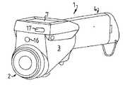
図1〜4に、本発明による赤外線カメラ1を示す。レンズ組立体2が提供されるが、こ
れは、交換可能であり、実質的に伸長形状のハウジング3の一方端に固定され、その反対
側の端部4は、使用者用ハンドルとして形成される。ハンドル部4のハウジング3の内側
に、電気エネルギー源5が、再充電可能電池の形態で適切に提供されるが、他の選択肢も
明らかに可能である。ハウジング3の内側には、レンズ組立体2を介して得られる情報を
受け取り、処理する処理装置6も提供される。The details and advantages of the invention will be apparent from the following description and the appended claims.
1 to 4 show an
ハンドル部4の前方の、ハウジング3の前部に、カメラ1を操作するためのユーザ・イ
ンタフェースが配置される。このインタフェースの配置構成は、視覚により、かつ片手だ
けにより、容易で迅速なカメラの制御および操作を提供することを目的とする。このよう
に、ハウジング3の前部の上面の前部に位置するディスプレイ7と、ハンドル部4の前方
に位置する手動制御手段とが提供される。手動制御手段に含まれるものとして、使用者の
親指によって操作されるように意図され、ディスプレイ7とハンドル部4との間に位置す
る、制御手段の第1の集合体8がある。本明細書で示す実施例では、この第1の集合体8
は、4つの押ボタン9〜12と、いくつかの方向に傾けることのできる操作レバー・ボタ
ン13とを含む。押ボタン9〜12は、円弧上に位置することが好ましく、その円弧の半
径は、実質的に、ハンドル部4を保持する使用者の親指の動きの半径に相応するものであ
る。押ボタンではなく、他の種類の手動制御手段も、当然使用することができる。また、
様々な手動制御手段の構成および数も可能である。A user interface for operating the
Includes four push buttons 9-12 and an operating lever button 13 which can be tilted in several directions. The push buttons 9 to 12 are preferably located on an arc, and the radius of the arc substantially corresponds to the radius of movement of the thumb of the user holding the
Various configurations and numbers of manual control means are possible.
手動制御手段に含まれるものとして、使用者の人差し指によって操作するように意図さ
れた、ハウジング3の下側の前部で、実質的に前記第1の集合体8の反対側に位置する、
制御手段の第2の集合体14もある。この実施例の場合、第2の集合体14は、カメラ1
の様々な機能を作動および停止させるために使用する引き金15を含む。カメラの所望の
設計、および意図する機能によって、当然他の実施例も可能である。一例として、ハウジ
ング3の前面に窓部16(図4)を有し、所望の対象物にカメラ1を向ける助けとなるこ
とを目的としたレーザを、引き金15によって作動および停止させることができる。As included in the manual control means, located at the lower front part of the
There is also a
The
状況によっては、任務遂行中に、測定結果や写真を制御センターに送信することが望ま
しい場合がある。この目的のために、カメラ1に、好ましくはハウジング3の前面(図4
)に、通信用窓部17を有する、IRDAリンク、または類似の無線通信用装置を含める
ことができる。また、ブルートゥース(Bluetooth)技術または類似の技術を使
用することもできる。必要な場合、同じ機器を使用して、赤外線画像または他の情報を、
直接または携帯電話で、コンピュータに転送することもできる。カメラに音響警報装置(
図示せず)を配置することもでき、これは、臨界温度が所定の安全範囲内にない対象物ま
たは対象領域を発見または指摘した時、可聴警報を発するように設定できる。このような
方法で、操作者に、視覚および音響の双方によって、重大な状況を知らせることができる
。In some situations, it may be desirable to send measurement results and photos to the control center while performing a mission. For this purpose, the
) May include an IRDA link or similar wireless communication device having a
It can also be transferred to a computer directly or with a mobile phone. An acoustic alarm device (
(Not shown) can also be placed, which can be set to generate an audible alert when an object or area of interest whose critical temperature is not within a predetermined safe range is found or pointed out. In this way, the operator can be informed of critical situations both visually and acoustically.
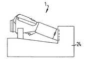
図5に示すとおり、ドッキング・ステーション(docking station)2
4にカメラを格納させるために、図3に示すとおりハンドル部4の後端または他の場所に
、蓋19を介して接触可能な接続部の集合体18を設けることができ、それによって、操
作装置6を、様々な目的で、また充電を行うために、基地局と交信させることができる。
ハンドル部4にホルダ20を設けることができ、それによって、カメラ1を、例えば使
用していない時に、操作者のベルトに掛けておくことができる。As shown in FIG. 5, a
In order to allow the camera to be retracted into the
A
図1のとおり、ハンドル部4は、長手方向軸線21を有し、レンズ組立体2は、光軸2
2を有する。これら2つの軸は、互いに平行であるか、または図示のとおり、互いに相対
的に角度αをなし、その角度の最大値は90°である。この角度αは、45°未満の値を
有することが好ましい。この角度αは、15〜30°の範囲内にあることが望ましく、実
質的には図面に示す通り約20°であることが有利である。As shown in FIG. 1, the
2 These two axes are parallel to each other or, as shown, make an angle α relative to each other with a maximum value of 90 °. This angle α preferably has a value of less than 45 °. This angle α is preferably in the range of 15-30 °, and is advantageously about 20 °, as shown in the drawing.
この実施例によれば、図6で概略的に示す通り、どちらの手でもカメラ1を保持するこ
とが可能であり、実線で示す通り、手を安定した低位置に保持し、ディスプレイ7の映像
を十分かつ容易に得ながら、カメラを対象物に向けることが可能となる。カメラを様々な
位置で保持する際、操作者25が、容易にディスプレイ7を見ることができるように、デ
ィスプレイを、可能な限りカメラの前部に配置することが好ましい。これは、良い映像を
得るために使用者が首を曲げる必要を軽減させる助けとなる。処理装置6によってディス
プレイ7で利用できるようにされたメニューの選択を行うために、操作者25は、親指と
人差し指で、適切なボタンを作動させて、所望の機能を選択することができる。カメラを
所望の対象物に向けることを簡単にするために、引き金15によって、カメラに含まれた
レーザを作動させることができる。一度対象物に向けられると、引き金15を使用して、
特別の写真を残すことができる。このカメラは、親指で操作するボタンによって、作動お
よび停止させることができる。必要に応じて、結果および画像を一時的に保存して、後で
都合の良い時にアンロードすることができる。カメラ1は、バランスを良くすることが容
易であり、とりわけエネルギー源5をハンドル部4に配置することによって、保持するた
めにより安定したものとなる。これはまた、従来の機器を使用した場合には、探し出すの
が困難で操作者を疲労させるような対象物を検査したい時に、操作を簡単にする助けとも
なる。According to this embodiment, as schematically shown in FIG. 6, the
You can leave a special photo. The camera can be activated and deactivated by a button operated with a thumb. If necessary, results and images can be temporarily saved and later unloaded at a convenient time. The
ハウジング3を頑丈にし、好ましくは防振ゴムを設けて耐震性を持たせることによって
、おそらくはLCD形式のディスプレイ7を、充分に保護されたものにする。それと同時
に、手動の操作手段を明瞭で、操作し易くすることによって、極めて携帯性が高く、便利
に使用でき、様々な分野で使用することのできるカメラが得られる。By making the
この創意に富んだカメラは、以上に示した通り、主に、サーモグラフ検査用の赤外線カ
メラとして意図されるものである。有利な実施例では、このカメラは、温度測定用として
も設計することができ、したがって、放射計カメラであることができる。適切な修正を行
えば他の応用も可能であるが、これも本発明の範囲に入るものである。As described above, this inventive camera is mainly intended as an infrared camera for thermograph inspection. In an advantageous embodiment, this camera can also be designed for temperature measurement and can therefore be a radiometer camera. Other applications are possible with appropriate modifications, which are within the scope of the present invention.
Claims (17)
Translated fromJapanese前部の第1面に赤外線を捉えるように適合され光軸を有するレンズ組立体が設けられ、後部に使用者用ハンドルが形成され、長手方向軸を有する細長いハウジングを備え、
前記前部と前記後部のバランスを良くするために、エネルギー源が、前記使用者用ハンドル内に位置し、
前記ハウジングの前部に設けられた、前記使用者用ハンドルと比較して幅が広い第2面であって、前記使用者用ハンドルを保持する使用者に相対する面にディスプレイが設けられ、
前記ハウジングの前部の前記第2面上において前記ディスプレイと前記使用者用ハンドルの間であって、前記使用者用ハンドルを保持する手の親指で操作可能な位置に、ハンドヘルド赤外線カメラの作動モードを選択及び制御するための第1の手動制御手段が設けられ、
前記ハウジング上の前記第1の手動制御手段と反対の面に、ハンドヘルド赤外線カメラの実行する機能を制御するために、前記使用者用ハンドルを保持する使用者の手の人差し指によって操作するようにされた引き金手段の形で、第2の手動制御手段が設けられた、
ハンドヘルド赤外線カメラ。A handheld infrared camerafor thermal imaging ,
A lens assemblyhaving an optical axis is provided onthe first frontsurface andadapted to capture infrared radiation, a user handle is formed at the rear,and includesan elongated housinghaving a longitudinal axis;
To improve the balance between the front and the rear, an energy source is located in the user handle,
A displayis provided on asecond surface provided at a front portionof the housing,which is wider than the user handle, and is opposed to a user holding the user handle ,
Be between the display and handle for the user onthe front part of the second surface of the housing, the operable position with the thumb of the hand holding the handle for theuser,the mode of operation of the handheldinfrared camera A first manual control meansis providedfor selecting and controlling
Opposite the first manual control means on the housing is operated by an index finger of a user's hand holding the user handle to control functions performed by a handheld infrared camera. A second manual control means is provided in the form of a trigger means;
Handheld infrared camera.
該円弧の中心が、前記使用者用ハンドルを把持する使用者の親指の内側関節の位置と一致するように配置されている
請求項1から3のいずれか1項に記載のハンドヘルド赤外線カメラ。The first manual control means includes an assembly of push buttons arranged in an arc shape,
The handheld infrared camera according to any one of claims 1 to 3, wherein a center of the arc is arranged so as to coincide with a position of an inner joint of a user's thumb holding the user handle.
前記押ボタンの集合体は、前記操作レバー・ボタンの両側に少なくとも1つずつ配置された少なくとも2つの押ボタンを含む
請求項4に記載のハンドヘルド赤外線カメラ。The first manual control means further includes an operation lever button.
The handheld infrared camera according to claim 4, wherein the assembly of the push buttons includes at least two push buttons arranged at least one on each side of the operation lever / button.
親指の動きの半径に相当する半径を有する円弧に配置された前記第1の手動制御手段の第1の集合体と、
前記ハウジングにおいて前記第1の手動制御手段の第1の集合体の反対側に配置された前記第1の手動制御手段の第2の集合体と
を含む
請求項1から15のいずれか1項に記載のハンドヘルド赤外線カメラ。The first manual control means includes:
A first set of saidfirst manual control means arranged in an arc having a radius corresponding to the radius of movement of the thumb,
The first of any one of claims 1 to15 and a second collection of arranged thefirst manual control means on the opposite side of the assembly of the in the housingfirst manual control means Handheld infrared camera as described.
Priority Applications (1)
| Application Number | Priority Date | Filing Date | Title |
|---|---|---|---|
| JP2011169090AJP5177595B2 (en) | 2011-08-02 | 2011-08-02 | Portable infrared camera |
Applications Claiming Priority (1)
| Application Number | Priority Date | Filing Date | Title |
|---|---|---|---|
| JP2011169090AJP5177595B2 (en) | 2011-08-02 | 2011-08-02 | Portable infrared camera |
Related Parent Applications (1)
| Application Number | Title | Priority Date | Filing Date |
|---|---|---|---|
| JP2002588123ADivisionJP2004534941A (en) | 2001-05-07 | 2001-05-07 | Portable infrared camera |
Publications (2)
| Publication Number | Publication Date |
|---|---|
| JP2011252921A JP2011252921A (en) | 2011-12-15 |
| JP5177595B2true JP5177595B2 (en) | 2013-04-03 |
Family
ID=45416933
Family Applications (1)
| Application Number | Title | Priority Date | Filing Date |
|---|---|---|---|
| JP2011169090AExpired - Fee RelatedJP5177595B2 (en) | 2011-08-02 | 2011-08-02 | Portable infrared camera |
Country Status (1)
| Country | Link |
|---|---|
| JP (1) | JP5177595B2 (en) |
Cited By (1)
| Publication number | Priority date | Publication date | Assignee | Title |
|---|---|---|---|---|
| US11754507B2 (en) | 2021-04-05 | 2023-09-12 | Lockheed Martin Corporation | Workforce augmenting inspection device |
Family Cites Families (10)
| Publication number | Priority date | Publication date | Assignee | Title |
|---|---|---|---|---|
| JP3059841B2 (en)* | 1992-10-15 | 2000-07-04 | 京セラ株式会社 | Electronic still camera with mobile phone function |
| JPH07115690A (en)* | 1993-10-15 | 1995-05-02 | Sony Corp | Remote operating system by remote controller |
| JPH08136351A (en)* | 1994-11-12 | 1996-05-31 | Horiba Ltd | Small sized radiation thermometer |
| WO1997008888A1 (en)* | 1995-08-25 | 1997-03-06 | Hitachi, Ltd. | Recorder equipped with video camera |
| JPH09325073A (en)* | 1996-06-05 | 1997-12-16 | Mitsubishi Electric Corp | Infrared camera |
| JPH09331590A (en)* | 1996-06-11 | 1997-12-22 | Car Mate Mfg Co Ltd | Information input / output device |
| JPH10112891A (en)* | 1996-08-14 | 1998-04-28 | Sony Corp | Remote controller |
| JP2001099714A (en)* | 1999-07-27 | 2001-04-13 | Yone Kk | Infrared camera |
| JP2001101101A (en)* | 1999-09-30 | 2001-04-13 | Casio Comput Co Ltd | Mail creation device, mail creation method, mail playback device, mail playback method, and mobile phone |
| JP2001103389A (en)* | 1999-09-30 | 2001-04-13 | Hitachi Ltd | Receiver and tuner |
- 2011
- 2011-08-02JPJP2011169090Apatent/JP5177595B2/ennot_activeExpired - Fee Related
Cited By (1)
| Publication number | Priority date | Publication date | Assignee | Title |
|---|---|---|---|---|
| US11754507B2 (en) | 2021-04-05 | 2023-09-12 | Lockheed Martin Corporation | Workforce augmenting inspection device |
Also Published As
| Publication number | Publication date |
|---|---|
| JP2011252921A (en) | 2011-12-15 |
Similar Documents
| Publication | Publication Date | Title |
|---|---|---|
| CN100414275C (en) | Handheld Infrared Camera | |
| US11131635B2 (en) | Infrared detection camera | |
| CN101430227B (en) | Ergonomic Configuration of Thermal Imagers | |
| US8466797B2 (en) | Handheld device for infrared temperature measurement with simultaneous image and temperature display | |
| JP4187329B2 (en) | Emissivity display method using one-handed instrument and one-handed instrument equipped with emissivity display means | |
| ES2688020T3 (en) | Camera focus systems with location tags | |
| CN107580690B (en) | Portable safety controls for industrial machines, especially robots | |
| KR20170050954A (en) | Smart device and method for contolling the same | |
| US20160076936A1 (en) | Method of attaching camera or imaging sensor to test and measurement tools | |
| EP2827581A2 (en) | Activity and/or environment driven annotation prompts for thermal imager | |
| US7168316B2 (en) | Humidity meter with non-contact temperature measurement | |
| JP5177595B2 (en) | Portable infrared camera | |
| JP2016091105A (en) | Smoke sensor | |
| US7452127B2 (en) | Anemometer with non-contact temperature measurement | |
| CN109154417B (en) | Improved handheld system for three-dimensional scanning with smart phone | |
| CN106574856A (en) | Sensor module with at least one interface | |
| CN2911629Y (en) | Non-contact infrared temp measurer with universa probe | |
| JP3697816B2 (en) | Patrol inspection support system | |
| US20140210987A1 (en) | Temperature Display Helmet | |
| CN105424192A (en) | Wearable thermal imager | |
| CN211373843U (en) | Thermal image device with light indicator | |
| JP6354985B2 (en) | Handheld ophthalmic device mounting table | |
| JP2007174140A (en) | Disaster victim searching apparatus | |
| JP2024043901A (en) | measuring device | |
| US20190250097A1 (en) | Device for gas detection and quantification |
Legal Events
| Date | Code | Title | Description |
|---|---|---|---|
| A131 | Notification of reasons for refusal | Free format text:JAPANESE INTERMEDIATE CODE: A131 Effective date:20120619 | |
| A601 | Written request for extension of time | Free format text:JAPANESE INTERMEDIATE CODE: A601 Effective date:20120918 | |
| A602 | Written permission of extension of time | Free format text:JAPANESE INTERMEDIATE CODE: A602 Effective date:20120921 | |
| A601 | Written request for extension of time | Free format text:JAPANESE INTERMEDIATE CODE: A601 Effective date:20121012 | |
| A602 | Written permission of extension of time | Free format text:JAPANESE INTERMEDIATE CODE: A602 Effective date:20121017 | |
| A521 | Request for written amendment filed | Free format text:JAPANESE INTERMEDIATE CODE: A523 Effective date:20121116 | |
| TRDD | Decision of grant or rejection written | ||
| A01 | Written decision to grant a patent or to grant a registration (utility model) | Free format text:JAPANESE INTERMEDIATE CODE: A01 Effective date:20121211 | |
| A61 | First payment of annual fees (during grant procedure) | Free format text:JAPANESE INTERMEDIATE CODE: A61 Effective date:20121226 | |
| R150 | Certificate of patent or registration of utility model | Ref document number:5177595 Country of ref document:JP Free format text:JAPANESE INTERMEDIATE CODE: R150 | |
| R250 | Receipt of annual fees | Free format text:JAPANESE INTERMEDIATE CODE: R250 | |
| R250 | Receipt of annual fees | Free format text:JAPANESE INTERMEDIATE CODE: R250 | |
| R250 | Receipt of annual fees | Free format text:JAPANESE INTERMEDIATE CODE: R250 | |
| LAPS | Cancellation because of no payment of annual fees |