JP5171878B2 - Control method of bodily sensation stimulation of vibration sensation feedback device - Google Patents
Control method of bodily sensation stimulation of vibration sensation feedback deviceDownload PDFInfo
- Publication number
- JP5171878B2 JP5171878B2JP2010105390AJP2010105390AJP5171878B2JP 5171878 B2JP5171878 B2JP 5171878B2JP 2010105390 AJP2010105390 AJP 2010105390AJP 2010105390 AJP2010105390 AJP 2010105390AJP 5171878 B2JP5171878 B2JP 5171878B2
- Authority
- JP
- Japan
- Prior art keywords
- vibration
- effect
- sensation
- output
- motor
- Prior art date
- Legal status (The legal status is an assumption and is not a legal conclusion. Google has not performed a legal analysis and makes no representation as to the accuracy of the status listed.)
- Expired - Lifetime
Links
Images


Classifications
- B—PERFORMING OPERATIONS; TRANSPORTING
- B06—GENERATING OR TRANSMITTING MECHANICAL VIBRATIONS IN GENERAL
- B06B—METHODS OR APPARATUS FOR GENERATING OR TRANSMITTING MECHANICAL VIBRATIONS OF INFRASONIC, SONIC, OR ULTRASONIC FREQUENCY, e.g. FOR PERFORMING MECHANICAL WORK IN GENERAL
- B06B1/00—Methods or apparatus for generating mechanical vibrations of infrasonic, sonic, or ultrasonic frequency
- B06B1/02—Methods or apparatus for generating mechanical vibrations of infrasonic, sonic, or ultrasonic frequency making use of electrical energy
- B06B1/0207—Driving circuits
- B06B1/0223—Driving circuits for generating signals continuous in time
- B06B1/0269—Driving circuits for generating signals continuous in time for generating multiple frequencies
- B06B1/0276—Driving circuits for generating signals continuous in time for generating multiple frequencies with simultaneous generation, e.g. with modulation, harmonics
- A—HUMAN NECESSITIES
- A63—SPORTS; GAMES; AMUSEMENTS
- A63F—CARD, BOARD, OR ROULETTE GAMES; INDOOR GAMES USING SMALL MOVING PLAYING BODIES; VIDEO GAMES; GAMES NOT OTHERWISE PROVIDED FOR
- A63F13/00—Video games, i.e. games using an electronically generated display having two or more dimensions
- A63F13/25—Output arrangements for video game devices
- A63F13/28—Output arrangements for video game devices responding to control signals received from the game device for affecting ambient conditions, e.g. for vibrating players' seats, activating scent dispensers or affecting temperature or light
- A63F13/285—Generating tactile feedback signals via the game input device, e.g. force feedback
- G—PHYSICS
- G06—COMPUTING OR CALCULATING; COUNTING
- G06F—ELECTRIC DIGITAL DATA PROCESSING
- G06F3/00—Input arrangements for transferring data to be processed into a form capable of being handled by the computer; Output arrangements for transferring data from processing unit to output unit, e.g. interface arrangements
- G06F3/01—Input arrangements or combined input and output arrangements for interaction between user and computer
- G06F3/016—Input arrangements with force or tactile feedback as computer generated output to the user
- A—HUMAN NECESSITIES
- A63—SPORTS; GAMES; AMUSEMENTS
- A63F—CARD, BOARD, OR ROULETTE GAMES; INDOOR GAMES USING SMALL MOVING PLAYING BODIES; VIDEO GAMES; GAMES NOT OTHERWISE PROVIDED FOR
- A63F2300/00—Features of games using an electronically generated display having two or more dimensions, e.g. on a television screen, showing representations related to the game
- A63F2300/10—Features of games using an electronically generated display having two or more dimensions, e.g. on a television screen, showing representations related to the game characterized by input arrangements for converting player-generated signals into game device control signals
- A63F2300/1025—Features of games using an electronically generated display having two or more dimensions, e.g. on a television screen, showing representations related to the game characterized by input arrangements for converting player-generated signals into game device control signals details of the interface with the game device, e.g. USB version detection
- A—HUMAN NECESSITIES
- A63—SPORTS; GAMES; AMUSEMENTS
- A63F—CARD, BOARD, OR ROULETTE GAMES; INDOOR GAMES USING SMALL MOVING PLAYING BODIES; VIDEO GAMES; GAMES NOT OTHERWISE PROVIDED FOR
- A63F2300/00—Features of games using an electronically generated display having two or more dimensions, e.g. on a television screen, showing representations related to the game
- A63F2300/10—Features of games using an electronically generated display having two or more dimensions, e.g. on a television screen, showing representations related to the game characterized by input arrangements for converting player-generated signals into game device control signals
- A63F2300/1037—Features of games using an electronically generated display having two or more dimensions, e.g. on a television screen, showing representations related to the game characterized by input arrangements for converting player-generated signals into game device control signals being specially adapted for converting control signals received from the game device into a haptic signal, e.g. using force feedback
- A—HUMAN NECESSITIES
- A63—SPORTS; GAMES; AMUSEMENTS
- A63F—CARD, BOARD, OR ROULETTE GAMES; INDOOR GAMES USING SMALL MOVING PLAYING BODIES; VIDEO GAMES; GAMES NOT OTHERWISE PROVIDED FOR
- A63F9/00—Games not otherwise provided for
- A63F9/24—Electric games; Games using electronic circuits not otherwise provided for
- G—PHYSICS
- G06—COMPUTING OR CALCULATING; COUNTING
- G06F—ELECTRIC DIGITAL DATA PROCESSING
- G06F2203/00—Indexing scheme relating to G06F3/00 - G06F3/048
- G06F2203/01—Indexing scheme relating to G06F3/01
- G06F2203/013—Force feedback applied to a game
- G—PHYSICS
- G06—COMPUTING OR CALCULATING; COUNTING
- G06F—ELECTRIC DIGITAL DATA PROCESSING
- G06F2203/00—Indexing scheme relating to G06F3/00 - G06F3/048
- G06F2203/01—Indexing scheme relating to G06F3/01
- G06F2203/014—Force feedback applied to GUI
Landscapes
- Engineering & Computer Science (AREA)
- Multimedia (AREA)
- General Engineering & Computer Science (AREA)
- Human Computer Interaction (AREA)
- Theoretical Computer Science (AREA)
- Mechanical Engineering (AREA)
- Physics & Mathematics (AREA)
- General Physics & Mathematics (AREA)
- User Interface Of Digital Computer (AREA)
- Position Input By Displaying (AREA)
Description
Translated fromJapanese本発明は、人間とコンピュータ間のインターフェイス装置の制御技術に関するものであり、特に、振動体感フィードバック装置の振動体感刺激効果の制御に関する。 The present invention relates to a technology for controlling an interface device between a human and a computer, and more particularly to control of a vibration sensation stimulation effect of a vibration sensation feedback device.
コンピュータ装置は、ゲームなどの娯楽活動に広く使用されている。現在、人気の高い任天堂の「ニンテンドー64」、ソニーの「プレイステイション」、セガの「ドリームキャスト(登録商標)」などのゲーム用コンピュータ装置には、家庭用テレビに接続するためのゲーム用コンソールが備わっている。これらゲーム用コンピュータ装置には、ウィンドウズ(登録商標)PC、マッキントッシュなどのパソコンも含まれる。また、任天堂の「ゲームボーイ」や、パームコンピュータ社の「パームパイロット」などの個人向け携帯情報端末、またノートパソコンなどのポータブルコンピュータ装置も、多くの場合娯楽目的で使用されている。 Computer devices are widely used for entertainment activities such as games. Currently, gaming computer devices such as Nintendo's “Nintendo 64”, Sony ’s “PlayStation”, and Sega's “Dreamcast (registered trademark)” have a console for connecting to a home TV. It is equipped. These game computer apparatuses include personal computers such as Windows (registered trademark) PC and Macintosh. In addition, personal portable information terminals such as Nintendo's “Game Boy” and Palm Computer's “Palm Pilot” and portable computer devices such as notebook computers are often used for entertainment purposes.
これらのコンピュータ装置のユーザは、一般的にホストコンピュータ(例えば、ゲーム用コンソール)に接続するインターフェイス機器を使用することで、ゲーム、またはその他のアプリケーションプログラムと相互動作可能になる。このようなインターフェイス装置としては、ジョイスティック、ゲームパッド、マウス、トラックボール、入力ペン、運転ハンドルなどがある。ユーザが、ジョイスティック、ハンドル、マウス、ボタンやその他のユーザ操作器(操縦桿)を動かすとホストコンピュータが感知して、ホストコンピュータに表示された画面を操作できる。最近では、インターフェイス装置上のホストコンピュータおよび/またはマイクロプロセッサが1つまたはそれ以上のモータを制御して、ユーザ側に作用力を出力するような、インターフェイス装置内での体感フィードバック処理が利用できるようになった。これらの作用力は、ユーザがゲーム体験やインターフェイスタスクをさらに実感できるよう、画面上の動作や対象物と相関関係にある。ここでいう「体感フィードバック」という表現は、体感(または振動体感)フィードバック処理(ユーザの皮膚へ伝達される作用力)と、筋感覚(力)フィードバック処理(操縦桿の自由操作の度合いで付与される作用力)との両方を意味する。 Users of these computing devices can generally interact with games or other application programs by using interface equipment that connects to a host computer (eg, a gaming console). Examples of such an interface device include a joystick, a game pad, a mouse, a trackball, an input pen, and a driving handle. When the user moves a joystick, a handle, a mouse, a button, or other user operation device (control stick), the host computer senses it and can operate a screen displayed on the host computer. Recently, a sensation feedback process in the interface device is available such that a host computer and / or microprocessor on the interface device controls one or more motors and outputs an acting force to the user. Became. These acting forces are correlated with operations on the screen and objects so that the user can further experience the game experience and interface tasks. The expression “feeling feedback” here is given by the feeling (or vibration feeling) feedback processing (acting force transmitted to the user's skin) and muscle sense (force) feedback processing (degree of free operation of the control stick). It means both.
ゲーム用コンソール市場において、これらの端末器は一般的に低コストで大量生産される。そのため、体感フィードバックインターフェイス装置はより単純な構造体でなくてはならず、その形態にも限界があった。現在使用されているフォースフィードバック可能な「ゲームパッド」コントローラ(または、ゲームパッド用のアドオンハードウェア)は、ソニーの「デュアルショック(登録商標)」、任天堂の「ランブルパック(登録商標)」、セガの「ジャンプパック」などの市販ゲーム用コンソールで作動するゲームと接続可能である。これらの装置は、1つまたはそれ以上のモータを採用してコントローラのハウジング部を振動させ、ゲームの進行と相互作動に関連した振動をユーザに出力する振動体感フィードバックコントローラである。一般的には、偏心型回転質量体(ERM)モータ、つまり、ページャモータを使ってコントローラ上に振動を発生させ、それをユーザへ伝達する。この種類のモータは、そのモータ主軸に質量体が回転軸オフセット取り付けされているため、主軸が回転すると質量体によりモータおよびゲームパッドのハウジング部が前後に揺動する。 In the gaming console market, these terminals are generally mass produced at low cost. For this reason, the sensation feedback interface device must have a simpler structure, and its form has a limit. Currently used force-feedback “gamepad” controllers (or add-on hardware for gamepads) include Sony's “Dual Shock”, Nintendo's “Rumble Pack”, Sega It can be connected to games that run on commercial game consoles such as “Jump Pack”. These devices are vibration sensation feedback controllers that employ one or more motors to vibrate the housing of the controller and output vibrations related to game progress and interaction to the user. In general, an eccentric rotating mass (ERM) motor, that is, a pager motor, is used to generate vibration on the controller and transmit it to the user. In this type of motor, the mass body is attached to the motor main shaft with a rotary shaft offset, and therefore, when the main shaft rotates, the motor and the housing of the game pad swing back and forth by the mass body.
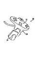
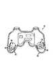
例として、「デュアルショック」コントローラと同類のゲームパッドコントローラ10を図1に示す。コントローラ10には、ユーザの方向入力用のd−パッド12、ボタン入力用のボタン14、方向入力用の1つ以上のジョイスティック16が備わっている。また、コントローラ10には、図3で以下に説明するような、コントローラのハウジング部と一体化した1つ以上のモータが搭載されている。ユーザは、コントローラの操作中両方のグリップ11をにぎることで、コントローラのハウジング部を通して振動を感じることができる。また別の構造で、任天堂のゲームパッドコントローラやランブルパックアドオンに類似したコントローラ20を図2に示す。この構造では、コントローラ10と同様の方向入力手段とボタン入力手段が、ゲームパッドコントローラ22に備わっているが、振動体感フィードバックのためのモータは搭載されていない。そこで、1つ以上のモータを有するアドオンユニット24をコントローラ22のインターフェイスポート26に接続することで、コントローラ22のハウジング部へ振動体感フィードバックさせることが可能になる。 As an example, FIG. 1 shows a
前記のコントローラ10の断面図を、図3に示す。コントローラ10では、2つの個別ERMモータを採用している。コントローラの片方のグリップ26内には、その回転主軸に連結し、小型質量体30を備えた小回転モータ28が搭載されており、もう一方のグリップ32内には、大型質量体36を備えた大型回転モータ34が搭載されている。モータ28と34はともに、一般的に単一トランジスタの電圧モード増幅器により駆動する。各モータを一方向へ一定速度で作動すれば、それぞれ連結する質量体が回転することになる。大型モータ34は、ユーザに対して、大きな振動量、つまり低周波を発生させるために、また、小型モータ28は、小さな振動量、つまり高周波を伝達するために駆動される。現状のデュアルショック仕様では、大型モータ34には8ビットの電圧変数が与えられているため、出力振動量は可変値である。小型モータ28の電圧は、オンかオフに設定されているので、出力振動量は一定値である。一般的に、コントローラのモータ28と34が同時に駆動することはないが、ある種のゲームにおいては、いずれのモータを作動させるかをユーザが決定できる。大型モータの速度は可変であって、一般的にはゲームプログラムから大型モータにDCコマンドを送り、各コマンドごとにモータから255種の振動例(例えば、255通りの異なる振動数)を出力させることが可能である。ホストコンソールユニットの各ゲームでは、ゲームイベントに振動体感フィードバックを相関させるコマンドつまり信号をコントローラに与えることにより、モータのオン・オフ制御が可能となる。 A sectional view of the
任天堂とセガのシステムで使用する「ランブルパック」と「ジャンプパック」の体感アドオンユニットでは、ERMと類似するモータを採用しているが、現状では振動出力に単一モータを使用している。例をあげると、「ランブルパック」のモータは単純にオン動作(最高値または、設定周波数で)とオフ動作だけであって、振動数は可変でない。「ジャンプパック」ではアナログ値を使用して、振動量を可変で制御している。また、「マッドキャッツデュアル作用力レーシングウィール」などの別のコントローラは、エキサイティングなゲーム用コンソールに適しており、ERMモータを使用するのと同様の振動体感フィードバックを提供できるハンドヘルドコントローラである。 The “rumble pack” and “jump pack” experience add-on units used in the Nintendo and Sega systems employ a motor similar to the ERM, but currently use a single motor for vibration output. For example, a “rumble pack” motor simply has an on operation (at the maximum value or set frequency) and an off operation, and the frequency is not variable. The “jump pack” uses analog values to control the amount of vibration variably. Another controller such as the “Mad Cats Dual Action Racing Wheel” is a handheld controller that is suitable for exciting gaming consoles and can provide vibration experience feedback similar to using an ERM motor.
従来技術による振動体感コントローラの問題点の1つは、出力振動数が振動量と密接に関連していることである。例えば、「デュアルショック」のコントローラでは、可能な複数振動作用の1つを出力した場合、その振動量と振動数が強く連携しているため、個別には変更できない。特定の振動数(質量体回転速度)が指示される場合、その振動数は振動量と相関関係があるため、ユーザに伝達されても、変動は不可能である。このため、これらの装置における出力体感フィードバックの範囲はかなり制限されてしまう。つまり、高振動量と高振動数、または、低振動数と低振動量のみ出力が可能であって、これらのパラメータを個別に変化させる機能はもたないのである。 One of the problems of the vibration sensation controller according to the prior art is that the output frequency is closely related to the vibration amount. For example, in the “dual shock” controller, when one of the possible multiple vibration actions is output, the vibration amount and the vibration frequency are strongly linked, and cannot be changed individually. When a specific frequency (mass body rotation speed) is instructed, the frequency is correlated with the amount of vibration, and therefore cannot be changed even if transmitted to the user. For this reason, the range of output sensation feedback in these devices is considerably limited. That is, only a high vibration amount and high frequency, or a low frequency and low vibration amount can be output, and there is no function for individually changing these parameters.
ゲーム用コンソールの振動体感コントローラは、PCなどのパソコン用の高性能なフォースフィードバック装置に比べて構造的に単純であるにもかかわらず、コンソール利用ゲームにおける体感フィードバックは、やはりユーザにとっては効果的で楽しいものである。さらに、操作具の作用軸に作用力を付与するような自動車ハンドルや飛行シュミレーション用ジョイスティックといった、コンソールの振動体感装置は、他の高性能な筋感覚性パソコン用のフォースフィードバック装置に比べて大幅に安価である。これらのコンソール用振動体感装置をパソコンに接続できれば、インターフェイス機器に高額なコストをかけずに体感フィードバックを楽しみたいというコンピュータユーザに対して、魅力的な選択技を提供できるのである。しかしながら、パソコンで使用する従来のフォースフィードバック制御法では、振動体感フィードバックを制御することが難しいという問題点がある。例えば、パソコン上で有効であるほとんどの体感フィードバックは、イマージョン社の「イマージョンプロトコル」とマイクロソフト社の「ダイレクトX」を使用しており、これによってゲームは、個別の振動数パラメータや振動量パラメータを使って振動力を制御できる。しかしながら、従来のゲームパッド振動体感装置と制御方法では、振動数と振動量を個別に制御することができない。さらに、従来のコンピュータプロトコルでは、ゲームにおいて振動だけでなくベクトル作用力、スプリング作用力、ダンピング作用力、テクスチャ作用力、またその他の作用力を含む、ゲームパッドコントローラやその他の振動体感コントローラでは未知である多様なフォースフィードバック効果を出力させることは不可能である。そこで必要なのは、もっと多様な振動体感出力を可能にするような振動体感フィードバック制御方法であり、また、振動体感コントローラを、さらに高性能な筋感覚性フォースフィードバック装置へ上記効果を出力するようなアプリケーションプログラムと互換性をもたせることである。 Although the game console vibration sensation controller is structurally simple compared to high-performance force feedback devices for personal computers such as PCs, sensation feedback in console games is still effective for users. It's fun. In addition, console vibration sensation devices, such as a car handle that applies an action force to the operating axis of the operating tool and a joystick for flight simulation, are significantly more powerful than force feedback devices for other high-performance muscle-sensitive PC Inexpensive. If these console vibration sensation devices can be connected to a personal computer, an attractive selection technique can be provided to computer users who want to enjoy sensation feedback without incurring expensive costs for interface equipment. However, the conventional force feedback control method used in a personal computer has a problem that it is difficult to control the vibration sensation feedback. For example, most bodily feedbacks that are valid on a personal computer use Immersion's "Immersion Protocol" and Microsoft's "Direct X", which allows the game to set individual frequency and vibration parameters. It can be used to control the vibration force. However, the conventional game pad vibration sensing device and control method cannot individually control the vibration frequency and vibration amount. In addition, conventional computer protocols are not known in game pad controllers and other vibration sensation controllers, including vector action force, spring action force, damping action force, texture action force, and other action forces as well as vibration in games. It is impossible to output a variety of force feedback effects. Therefore, what is needed is a vibration sensation feedback control method that enables a greater variety of vibration sensation outputs, and applications that output the above effects to the vibration sensation controller to a higher-performance muscle sensory force feedback device. To make it compatible with the program.
本発明は、コンピュータに接続された振動体感フィードバック装置により運動感覚性作用力刺激をマッピング処理して振動体感刺激に変えることを目的としている。回転質量体を一方向に駆動し、その結果たる振動の振動量と振動数をそれぞれ別途に制御するような体感フィードバック装置から、高度な振動体感を出力させることが可能となる。その他の運動感覚性効果もマッピング処理により、振動やモータ制御方法に変換できる。 An object of the present invention is to perform mapping processing of a kinematic sensory action force stimulus to a vibration experience stimulus by a vibration experience feedback device connected to a computer. It is possible to output a high degree of vibration feeling from a feeling feedback device that drives the rotating mass body in one direction and separately controls the vibration amount and frequency of the resulting vibration. Other kinematic effects can also be converted into vibration and motor control methods by mapping processing.
特に、本発明の態様の1つは、ホストコンピュータからゲームパッドやマウスなどの振動体感インターフェイス装置を制御する点である。その振動体感インターフェイス装置によりユーザへ出力される所望の体感効果を決定するために、それぞれ独立した振動量や振動数を示す情報が振動体感インターフェイス装置に入力される。その効果情報に基づいた周期制御信号により、振動体感装置の回転モータを駆動して質量体を回転させて、質量体の回転からユーザに出力される振動量と振動数をもつ振動を発生させるのである。振動量は、制御信号のデューティサイクルで決まり、振動数は、制御信号の周波数で決まる。実施例の1つでは、制御信号がオンとオフの動作だけで、各振動周期のオン期間に信号がオンになり振動量が決められる。前記の情報には、装置動作用の少なくとも1個のパラメータと高位コマンドが含まれている。または、情報が制御信号とほぼ等価であっても構わない。制御信号により、モータが一方向へのみ駆動される。 In particular, one aspect of the present invention is to control a vibration experience interface device such as a game pad or a mouse from a host computer. In order to determine a desired bodily sensation effect output to the user by the vibration bodily sensation interface device, information indicating independent vibration amount and frequency is input to the vibration bodily sensation interface device. Due to the periodic control signal based on the effect information, the rotation body of the vibration sensation device is driven to rotate the mass body, and the vibration having the vibration amount and the frequency output to the user from the rotation of the mass body is generated. is there. The amount of vibration is determined by the duty cycle of the control signal, and the frequency is determined by the frequency of the control signal. In one embodiment, the control signal is only turned on and off, and the signal is turned on during the on period of each vibration cycle to determine the amount of vibration. The information includes at least one parameter for operating the device and a high level command. Alternatively, the information may be substantially equivalent to the control signal. The motor is driven only in one direction by the control signal.
本発明の別の態様として、ホストコンピュータに接続された体感フィードバック装置に振動を与える方法は、回転可能な質量体を備えた、体感ファイードバック装置のアクチュエータを準備する工程と、制御信号を作成するための情報を体感フィードバック装置に入力する工程とから成る。制御信号によりアクチュエータを駆動制御して、質量の回転から装置を振動させるため質量体を回転軸を中心に回転させるのであって、その振動の振動量と振動数は制御信号を調整することによりそれぞれ別途に調整可能である。なお、振動量は、制御信号のデューティサイクルに基づいて決定され、振動数は、制御信号の周波数に基づいて決定される。そして制御信号は、各振動周期の所定時点に供与されるのある。制御信号のオン期間は、振動周期のパーセントで、または、各振動周期の所定の時間長で示すことが可能である。振動が出力される前に質量体を回転開始するような開始制御信号をアクチュエータに送る方法も、質量体の回転を確実にするのに利用できる。また、同様の特徴を備えた体感フェイードバック装置をも開示してある。実施例によっては、質量体を双方向に回転移動させても構わない。 As another aspect of the present invention, a method for applying vibration to a sensation feedback device connected to a host computer includes the steps of preparing an actuator for a sensation feedback device having a rotatable mass body, and generating a control signal Input to the sensation feedback device. The actuator is driven and controlled by the control signal, and the mass body is rotated around the rotation axis in order to vibrate the device from the rotation of the mass. The vibration amount and the frequency of the vibration are adjusted by adjusting the control signal. It can be adjusted separately. Note that the vibration amount is determined based on the duty cycle of the control signal, and the vibration frequency is determined based on the frequency of the control signal. A control signal is provided at a predetermined point in each vibration cycle. The ON period of the control signal can be expressed as a percentage of the vibration period or a predetermined time length of each vibration period. A method of sending a start control signal to the actuator to start rotating the mass body before the vibration is output can also be used to ensure the rotation of the mass body. A bodily sensation fadeback device having similar characteristics is also disclosed. Depending on the embodiment, the mass body may be rotated in both directions.
本発明のさらなる別の態様として、振動体感インターフェイス装置で運動感覚性効果を出力させる方法は、ユーザが操作する運動感覚性体感フィードバック装置の少なくとも1つの操作の自由度において作用力を出力させるような運動感覚性体感効果を示すコマンドを入力する工程からなる。運動感覚性効果は、マッピング処理により、振動体感装置に接触するユーザに出力される振動体感作用力を発生する振動体感効果に変換される。振動体感効果は、振動体感インターフェイス装置により出力される。運動感覚性体感効果は、所定の振幅値と周波数をもつ周期性効果であってもよいが、その場合、マッピング処理された振動体感効果は等価な振動量と振動数をもつ振動となる。運動感覚性体感効果がバネ効果、ダンパー効果、障害効果、ベクトル効果などの非周期性効果である場合、マッピング処理された振動体感効果は非周期性効果の振幅値に基づいた振動量の振動となる。 As yet another aspect of the present invention, a method for outputting a kinematic sensory effect with a vibration sensory interface device is one that outputs an action force in at least one degree of freedom of operation of a kinematic sensory feedback device operated by a user. It consists of a step of inputting a command indicating a kinematic sensory effect. The kinematic sensory effect is converted into a vibration sensory effect that generates a vibration sensory action force output to a user who touches the vibration sensory device by mapping processing. The vibration sensation effect is output by the vibration sensation interface device. The kinematic sensory sensation effect may be a periodic effect having a predetermined amplitude value and frequency. In this case, the mapped vibration sensation effect is a vibration having an equivalent vibration amount and frequency. When the kinematic sensory effect is an aperiodic effect such as a spring effect, a damper effect, a failure effect, or a vector effect, the mapped vibration sensory effect is a vibration with a vibration amount based on the amplitude value of the aperiodic effect. Become.
さらに、本発明による特徴的な方法は、振動体感インターフェイス装置でより高度な作用力効果を出力させる方法である。また、本発明の振動体感フェードバック装置は、制御信号のデューティサイクルと周波数を利用した偏心回転質量体モータによる振動出力の振動量や振動数をそれぞれ独立して制御および指定でき、低価格の単方向の増幅器や制御回路を利用している。運動感覚性作用力をマッピング処理して振動体感効果に変換する技術により、振動体感装置の体感効果を制御できる運動感覚性フォースフィードバック装置を制御するためのソフトが実現可能である。それゆえ、刺激的なコンピュータソフトの高度な体感フィードバック効果を体験するのに、より安価な振動体感装置をユーザに選択させることができるのである。 Furthermore, a characteristic method according to the present invention is a method for outputting a higher acting force effect in the vibration experience interface device. In addition, the vibration sensation fade-back device of the present invention can independently control and specify the vibration amount and frequency of the vibration output by the eccentric rotating mass motor using the duty cycle and frequency of the control signal, and can be used at a low cost. Directional amplifiers and control circuits are used. Software for controlling the kinesthetic force feedback device that can control the sensation effect of the vibration sensation device can be realized by a technique of mapping the kinesthetic sensation force and converting it into a vibration sensation effect. Therefore, in order to experience the advanced sensation feedback effect of stimulating computer software, the user can select a cheaper vibration sensation apparatus.
本発明の上記およびその他の特徴は、以下の本発明の説明の熟読や複数の図面の査定から、当業者には明白となろう。 These and other features of the present invention will become apparent to those skilled in the art from a reading of the following description of the invention and an assessment of the drawings.
本出願では、振動体感コントローラによる振動体感フィードバックの出力強化技術に加えて、体感フィードバックゲームパッドなどの高性能の作用力効果を利用した振動体感インターフェイスコントローラの制御技術について説明する。ここでは、その装置のユーザへ振動を出力するコントローラ、つまり、インターフェイス装置を、「振動体感装置」または、「振動体感フィードバック装置」という表現で示しており、これらの装置には、ゲームパッド、ハンドヘルド式操縦ハンドル、フィッシングコントローラ、ジョイスティック、マウス、トラックボール、アダルトデバイス、グリップ、リモートコントローラ、ハンドヘルド式ゲーム装置、平面スクリーン、入力ペンなどがあげられる。対称的に、「運動感覚性装置」または、それに相似する表現は、その装置の主軸に沿った力、つまり、装置の操作具の動きの自由度に応じた作用力を付与する装置を指す。 In the present application, in addition to the output enhancement technology of the vibration sensation feedback by the vibration sensation controller, a control technology of the vibration sensation interface controller using a high performance action force effect such as a sensation feedback game pad will be described. Here, a controller that outputs vibration to the user of the device, that is, an interface device is indicated by the expression “vibration sensation device” or “vibration sensation feedback device”. Type steering handle, fishing controller, joystick, mouse, trackball, adult device, grip, remote controller, handheld game device, flat screen, input pen, etc. In contrast, a “kinematic device” or similar expression refers to a device that applies a force along the principal axis of the device, that is, an acting force depending on the degree of freedom of movement of the operating tool of the device.
図4は、本発明に採用するのに適当な、体感システム100を示したブロック図である。システム100には、ホストコンピュータ102と振動体感装置104が備わっている。 FIG. 4 is a block diagram showing a
ホストコンピュータ102は、多様な演算装置や電子装置から選択できる。好ましい一実施例においては、コンピュータ102として、PC互換性コンピュータ、マッキントッシュパソコン、または、任天堂やセガ、ソニー、マイクロソフト社のゲームコンソール装置といったパソコンやゲームコンソール、または、ワークステーションを使用している。また別の実施例として、ホストコンピュータ102に、例えば双方向テレビ機能をユーザに提供するための「セットトップボックス」を採用してもかまわない。「ネットワークコンピュータ」や「インターネットコンピュータ」といった、インターネットやワールドワイドウェブに使用する標準的な接続やプロトコルを使ってユーザを地域的、または海外ネットワークと情報交換可能にするような装置でもよい。いくつかの実施例では、ハンドヘルド型ビデオゲームユニットや、ポータブルコンピュータ、アーケードゲーム機などの、ユーザが持ったり接触したりするインターフェイス装置や操作装置といったケース、つまり同じハウジング部内に、ホストコンピュータ102を設置している。ホストコンピュータには、ホストマイクロプロセッサ、随時書き込み読み出しメモリ(RAM)、読み込み専用メモリ(ROM)、入出力(I/O)回路、音響出力装置、その他当業者にとっては周知であるコンピュータ部品が装備されていることが好ましい。また、記憶装置(ハードディスクドライブ、CDROMドライブ、フロッピー(登録商標)ディスクドライブなど)、プリンタ、その他の入出力装置などの周辺機器も、ホストコンピュータ102に接続可能である。 The
表示装置106は、コンピュータ102に接続されているか、その一部を形成していることが好ましく、この装置によりゲーム環境、オペレーティングシステムのアプリケーション、シュミレーション等のグラフィック環境の画像が表示される。表示装置106には、LCDディスプレイ、LEDディスプレイ、CRTディスプレイや、平面パネルスクリーン、ディスプレイゴーグルといった多様な種類のうち、どの装置を採用してもかまわない。 The
ホストコンピュータ102は、必要に応じて、インターフェイス装置104とその他の周辺機器を介してユーザが相互作用できるような、ホストアプリケーションプログラムを実行することが好ましい。例えば、このホストアプリケーションプログラムは、ビデオゲーム、ワードプロセッサ、またはスプレッドシート、HTMLまたはVRML命令を実行するウェブページやブラウザ、科学分析プログラム、バーチャルリアリティトレーニング用プログラムまたはアプリケーション、またはその他、装置104の入力を利用して体感フィードバックコマンドを装置104へ出力する(或いは、ホスト上のAPIやドライバプログラムなどの異なるレイヤーがこの命令を出力してもよい)ようなアプリケーションプログラムであって構わない。このホストプログラムでは、装置104の電子とセンサから受信する入力信号をチェックし、作用力値および/またはコマンドを装置104の作用力出力部へ出力する。これらのシュミレーションソフトウェアとコンピュータの入出力(I/O)装置を接続させるのに適当なソフトウェアドライバは、カリフォルニア州サンホセにあるイマージョンコーポレーションが提供している。 The
プログラムにおける数層の異なるレイヤーを、ホストコンピュータ102で実行することができる。例えば、アプリケーションレイヤーでは、ゲームプログラムやワードプロセッサなどの1つ以上のアプリケーションプログラムの実行が可能である。また、アプリケーションプログラミングインターフェイス(API)レイヤー(例えば、マイクロソフト社のウィンドウズ(登録商標)で使用されている)や別のドライバレイヤーなどの数層のサブレイヤーも使用可能である。アプリケーションプログラムは作用力を直接命令でき、ドライバプログラムはアプリケーションプログラム内の相互作用をモニタして、設定条件が合えば体感効果を命令することができる。ある一実施例では、体感フィードバックドライバプログラムが運動感覚コマンドをアプリケーションプログラムから受け取り、そのコマンドを体感コマンドにマッピング変換して効果を出力する。その後、必要な情報がインターフェイス装置104に伝送される。 Several different layers in the program can be executed on the
振動体感装置104は、二方向バス108によってホストコンピュータ102と接続している。この二方向バスは、ホストコンピュータ102とインターフェイス装置間の、いずれの方向にも信号を伝送することができる。例として、バス108は、RS232シリアルインターフェイス、RS‐422ユニバーサルシリアルバス(UBS)、MIDI、または当業者には周知であるその他のプロトコルであって構わないし、または、並行バスやワイヤレスリンクでもよい。例えば、標準USBでは、装置104のアクチュエータにも電力供給が可能な、比較的高速度のインターフェイスを提供できる。 The
振動体感装置104は、多くの実施例においてローカルマイクロプロセッサ110を内蔵している。ローカルマイクロプロセッサ110は、装置内の個別の部品間の通信効率を高めるために、任意で装置104のハウジング部に装備しても構わない。プロセッサ110は、装置104のローカルプロセッサと考えられる。ここでの「ローカル」とは、プロセッサ110がホストコンピュータ102内のどのプロセッサからも隔離されたマイクロプロセッサであることを意味する。また、「ローカル」は、装置104の体感フィードバックとセンサI/O専用のプロセッサ110も指す。マイクロプロセッサ110は、ソフトウェアの命令によって、ホスト102からのコマンドまたは要求の入力を待機し、そのコマンドまたは要求を復号化または一次停止し、そのコマンドまたは要求に応じた入出力信号を処理/制御するよう設定できる。いくつかの実施例では、プロセッサ110は、センサ信号を読み取り、そのセンサ信号、時間信号、および、高位ホストコマンドに応じて選択された記憶またはリレー処理された命令から所定の作用力を算出することにより、ホストコンピュータ102から独立して作動することが可能である。ローカルマイクロプロセッサ110としての使用に適したマイクロプロセッサには、PCなどのパソコンで使用されている現在バージョンの「イマージョンタッチセンス」プロセッサのような、より高性能のフォースフィードバックプロセッサだけでなく、モトローラ社のMC68HC711E9、マイクロチップ社のPICI6C74、インテル社の82930AXなどがある。マイクロプロセッサ110は、1個のマイクロプロセッサチップ、複数のプロセッサおよび/またはプロセッサ、および/またはデジタル信号プロセッサ(DSP)機能を備えている。本発明で説明される制御技術は、例えば、ローカルマイクロプロセッサのブロック110に、マイクロプロセッサに加えエンコーダ処理回路、通信回路、PWM回路などの関連部品を備えた「イマージョンタッチセンスプロセッサ」のファームウェアで実行可能である。偏心型回転質量体(ERM)モータで実行できる、さらに高度な周期効果や刺激効果(イマージョンプロトコルで作成される)を出力する様々な技術は、マイクロプロセッサ110のファームウェアで提供できる。 The
マイクロプロセッサ110は、センサ112から信号を受け取り、バス108を介してホストコンピュータ102から出されたインストラクションに従って、アクチュエータ120と122に信号を伝送する。マイクロプロセッサ110は、ここで「制御信号」として定義される信号111を発信する。実施例の1つでは、この制御信号は、プロセッサ110のファームウェアで作成され、アクチュエータのインターフェイス124へ送られるPWM信号である。各モータごとに1つの制御信号があるのが好ましく、説明した実施例では2つの制御信号が入力される。ここで使う表現「オン期間」とは、この制御信号が高位に変わった後継続して高位である制御信号の期間をいう。後で更に詳しく説明するが、この制御信号によってアクチュエータのドライブ信号が作成される。
ローカル制御の一実施例では、ホストコンピュータ102が、バス108を介して高位の監督コマンドをマイクロプロセッサ110に伝送する。マイクロプロセッサ110がこのコマンドを復号化し、ホストコンピュータ102から独立して高位コマンドに応じて、アクチュエータとセンサーへの低位の作用力制御ループとを管理する。このオペレーションについては、本出願書に参照として付随された、米国特許第5,739,811号と第5,734,373号に詳細に記載されている。前記のホスト制御ループにおいて、作用力コマンドは、ホストコンピュータからマイクロプロセッサ110へ出力され、作用力、つまり、一定の特性をもつ作用力刺激を出力するようマイクロプロセッサに指示する。ローカルマイクロプロセッサ110は、1つ以上の自由度におけるマウスの位置を示す位置データなどのデータをホストコンピュータへ伝達する。このデータは、また、装置104内のボタンスイッチまたは別の部品の状態も示す。ホストコンピュータは、このデータを使って実行プログラムを更新する。ローカル制御ループでは、マイクロプロセッサからアクチュエータへ、アクチュエータ信号が伝送され、センサ112とその他の入力装置からマイクロプロセッサ110へ、センサ信号が伝送される。マイクロプロセッサ110は、入力されたセンサ信号を記憶した指示に従って処理することで、適当な出力アクチュエータ制御信号を決定できる。このマイクロプロセッサでは、出力作用力のローカル決定において、ホストコンピュータへセンサ信号から引き出した位置データを伝送するだけでなく、センサ信号を使用しても構わない。 In one embodiment of local control, the
また別の実施例では、マイクロプロセッサ110と同様の機能を提供するために、装置104に他のハードウェアをローカル的に設置している。例えば、固定論理と一体化したハードウェア型機器を使用して、アクチュエータに信号を送り、センサ112からセンサ信号を受信し、所定のシーケンス、アルゴリズム、または工程にしたがって体感信号を入力することが可能である。ハードウェアで所望機能の論理を実行する技術は、当業者にとっては公知のものである。このようなハードウェアは、本発明による装置のようにあまり複雑でないフォースフィードバック装置にも適用できる。 In another embodiment, other hardware is installed locally on the
また別の、ホストコントロールによる実施例では、ホストコンピュータ102が、バス108を通してマイクロプロセッサ110か、(マイクロプロセッサ110がない場合)別の回路を介してアクチュエータに直接伝送する低位作用力コマンドを付与できる。ホストコンピュータ102は、このように装置104が送受信する全信号を制御し、処理する。例えば、ホストコンピュータが、アクチュエータ120か122が出力する作用力を直接制御し、センサ112と入力装置126からのセンサ信号を直接受信するのである。この実施例では、装置104では、複雑なローカルマイクロプロセッサ110、または、別の処理回路が必要ないので、フォースフィードバック装置のコストをさらに低減することが可能である。このホスト102はまた、本出願に付随の米国特許第5,959,613号に記載のように、アクチュエータに伝送される作用力値を伝送することもできる。 In another host-controlled embodiment, the
最も単純なホストコントロールの実施例では、ホストから装置へ伝送される信号は、予め設定された周波数と振幅値でアクチュエータをパルス処理するかどうかを示すシングルビットの信号であってもよい。さらに複雑な実施例では、ホストからの信号に、所望のパルス値を決定する振幅値、および/または、周波数を内包することが可能である。ローカルプロセッサを使用して、ある時間分だけ作用する所望の作用力値を示す簡単なコマンドをホストから受信するので、前記のマイクロプロセッサは、そのコマンドに基づいた所定の期間に作用力値を出力できる。前記のホストコマンドは、米国特許第5,959,613号に開示のように、作用力を形成するための「エンビロープ」を特定し、作用力出力時に付与することもできる。さらに、米国特許第5,959,613号で記載されているとおり、作用力値(振動量など)をリアルタイムで装置から出力できるよう、ホストコンピュータから出力される。上述した複数の方法を合成して、単一装置104に使用することも可能である。 In the simplest host control embodiment, the signal transmitted from the host to the device may be a single bit signal indicating whether to pulse the actuator with a preset frequency and amplitude value. In a more complex embodiment, the signal from the host can include an amplitude value and / or frequency that determines the desired pulse value. Using a local processor, a simple command is received from the host indicating the desired force value acting for a certain amount of time, so the microprocessor outputs the force value for a predetermined period based on that command. it can. As disclosed in US Pat. No. 5,959,613, the above-mentioned host command can specify an “environment” for forming an acting force, and can be given when the acting force is output. Further, as described in US Pat. No. 5,959,613, the force value (vibration amount, etc.) is output from the host computer so that it can be output from the apparatus in real time. It is also possible to combine a plurality of the methods described above and use them for a
RAMおよび/またはROMなどのローカルメモリを、装置104のマイクロプロセッサ110に接続して、マイクロプロセッサ110のコマンドまたはその他のデータを一時的に記憶させることが可能である。たとえば、マイクロプロセッサから出力可能であって記憶された作用力値のシーケンスや、アプリケーションプログラム、または別の条件で進行中のイベントに基づいて出力される作用力値のルックアップテーブルなどの作用力特性もメモリに記憶できる。さらに、アクチュエータで作用力出力(例えば、時間依存要素による作用力)を演算する場合に必要なタイミングデータを得るために、ローカルクロックをマイクロプロセッサ110に接続してもよい。USB通信インターフェイスを使用する実施例では、マイクロプロセッサ110のタイミングデータをUSB信号で補うことが可能である。 Local memory, such as RAM and / or ROM, can be connected to the
センサー112は、装置104の操作具114の位置や動作を検知して、その位置や動作を示す情報を含む信号を、マイクロプロセッサ110(またはホスト102)に伝送する。いくつかの実施例において、この操作具はゲームパッドのコントローラに付属の小型ジョイスティックであり、ホストコンピュータにコントロール入力するようユーザが双方向回転、または、直線で自由に操作できるものである。また別の実施例では、前記の操作具として、4つ以上の方向でホストコンピュータに入力できる方向パッドを使用している。その他、前記の操作具は、回転ダイル、リニアスライダー、ハンドル、フィンガーレセプタクル、シリンダ、などの制御部材であっても構わない。また、マウスや、3−D空間におけるゲームパッドの位置を検知するその他のコントローラのように、操作具がその装置自体のハウジング部を構成していてもよい。ジョイステックや、その他の操作具の位置を検知するのに適したセンサには、当業者には周知の、回転ボールやシリンダに摩擦結合したデジタル光学エンコーダがある。メカニカルスイッチ、線形光学エンコーダ、ポテンションメータ、光学センサ、速度センサ、加速センサ、張力ゲージ、その他のセンサも使用可能であり、相対センサでも絶対センサでも構わない。当業者には周知のように、光学センサインターフェイス116では、センサ信号を、マイクロプロセッサ110および/またはホストコンピュータ102で読み取り可能な信号に変換する。 The
アクチュエータ120と122では、マイクロプロセッサ110および/またはホストコンピュータ102からの信号、またはコマンドに応じて、装置104のユーザへ作用力を伝達する。記載の一実施例では、2個のアクチュエータ、小型アクチュエータ120と大型アクチュエータ122、を配備している。この好ましい実施例では、これらのアクチュエータに、モータの回転主軸に取り付けられた偏心質量体をもつ回転モータの偏心型回転質量体(ERM)DCモータを採用している。モータが回転すると、回転する質量体からの慣性力がモータのハウジング部またはハウジング部に接続された部品に振動が発生して、ハウジング部を把持または接触するユーザに振動体感刺激を伝達するのである。アクチュエータ120と122はこのようにして、「情報伝達」つまり「効果」の振動体感作用力を提供するのである。小型モータ120は高振動数で低振動量の作用力を、大型モータ122は低振動数で高振動量の作用力を出力する。
また別の実施例では、同一サイズまたは異なるサイズの1個または2個以上のアクチュエータにより、装置104のユーザへ振動体感刺激や作用力を伝達している。この場合、偏心型質量体を一方向へ回転させるような、ボイスコイルアクチュエータ、可動磁石アクチュエータ、水力または空動アクチュエータ、トルク型、ブラシ式または非ブラシ式モータなど、多種類のアクチュエータの使用が可能である。さらに、追加アクチュエータを採用して、操作具114に運動感覚性フォースフィードバックを付与することもできる。 In another embodiment, the vibration bodily sensation stimulus and the acting force are transmitted to the user of the
マイクロプロセッサ110からの信号を、アクチュエータの駆動に適した信号に変換するために、アクチュエータ120と122とマイクロプロセッサ110との間に、アクチュエータインターフェイス124を任意で接続してもよい。インターフェイス124には、電力増幅器、スイッチ、デジタルアナログコントローラ(DAC)、アナログデジタルコントローラ(ADC)、その他当業者には周知の部品が装備されている。例えば、ある一実施例では、アクチュエータ120と122に、入手が簡単な単方向駆動のERMモータを採用している。モータ駆動用のアクチュエータインターフェイス124に使用される単指向性電圧モードの増幅器は、低価格の機器である。 An
また、別の入力装置118も装置104に内蔵されており、ユーザが操作すると、入力信号をマイクロプロセッサ110、またはホスト102へ伝送する。これらの入力装置としては、ボタン、ダイアル、スイッチ、スクロールハンドル、その他の制御器や機器があげられる。電力供給部120も、任意で装置104に内蔵、または接続可能であり、アクチュエータへ電力を供給するため、アクチュエータインターフェイス124および/またはアクチュエータ120と122に接続できる。別のさらに好ましい方法として、USBやその他を使用したバス108から電力を入力する方法もある。また、入力された電力を装置104で蓄電し制御して、アクチュエータ120と122の駆動必要時や補充目的に使用することもできる。USBの電力供給容量に制約があるため、最高の作用力を安定供給するには、マウス装置内に蓄電装置が必要になる(付随の米国特許第5,929,607を参照)。つまり、電力はコンデンサ、つまりバッテリに長時間蓄電され、振動体感を出力するため直ちに給電されるのである。また別の方法として、この技術をワイヤレス装置104に採用し、バッテリの電力を振動体感アクチュエータの駆動に使用することも可能である。 Another input device 118 is also built in the
以下に述べる本発明の多様な制御特性のために、図1〜3に示すような従来のコンソールゲームパッドのインターフェイス装置を、インターフェイス装置104として利用が可能である。また別の実施例では、インターフェイス装置でより高性能な振動体感を制御して出力できるよう、従来のゲームパッドコントローラに、より高性能なローカルマイクロプロセッサを搭載している。例えば、プレイステイションコンソール用のソニーのデュアルショックと互換性のある製品を、イマージョンタッチレスプロセッサと互換性のあるマイクロプロセッサで使用できるように修正して、モータとエレクトロニクスは従来のまま使用することも可能である。しかしながら、本発明の振動体感コントローラが必要とする部品は、従来技術の標準的なコンソール機器からは得られないので、必要であれば、またはより優れた振動体感出力を提供するには、特定の部品を使用すればよい。例として、デュアルショック用コントローラでは、特別なプレイステイション用バスと知財プロトコルを使用しており、PC規格ではユニバーサルシリアルバス(USB)かシリアルプロトコルを使用し、「ダイレクトX」/「イマージョン」と互換性をもたせている。マイクロソフト社の「ダイレクトX」は、PC上で動作されるウィンドウズ(登録商標)のオペレーションシステムにおける一連の条件と体感効果を提供する。マッキントッシュやその他のコンピュータやシステムなどでは、これらのプラットフォームを使用するために、また別の標準プロトコルとインターフェイスが採用される。その他の実施例においては、ユーザへ振動を出力する振動体感インターフェイス装置を、ゲームパッド、ハンドヘルド式または卓上設置式ハンドル、フィッシング型コントローラ、ジョイステック、マウス、トラックボール、アダルト装置、グリップ、リモートコントロール、ハンドヘルド式ゲーム装置、平面スクリーン、入力ペンなどの振動体感制御機器と併用している。 Due to various control characteristics of the present invention described below, a conventional console game pad interface device as shown in FIGS. In another embodiment, a conventional high performance local microprocessor is mounted on a conventional game pad controller so that a higher performance vibration experience can be controlled and output by the interface device. For example, Sony dual shock compatible products for playstation consoles can be modified to work with microprocessors compatible with immersion touchless processors, allowing motors and electronics to remain used. Is possible. However, since the components required by the vibration sensation controller of the present invention cannot be obtained from standard console equipment of the prior art, a specific vibration sensation output is necessary if necessary or better. Parts can be used. For example, a dual shock controller uses a special playstation bus and intellectual property protocol, and the PC standard uses a universal serial bus (USB) or serial protocol, and “Direct X” / “Immersion” It has compatibility. Microsoft's “Direct X” provides a series of conditions and sensations in a Windows® operating system running on a PC. Macintosh and other computers and systems use different standard protocols and interfaces to use these platforms. In other embodiments, the vibration sensation interface device that outputs vibrations to the user is a game pad, handheld or table-top handle, fishing controller, joystick, mouse, trackball, adult device, grip, remote control, It is used in combination with hand-held game devices, flat screens, vibration sensation control devices such as input pens.
駆動方法
上述したERMモータは安価であるので、量産用体感フィードバック装置への使用に適している。しかしながら、後述するようにERMモータの振動体感を出力するには、異なる方法で動作させても構わない。いくつかの実施例では、所望される振動体感の種類に応じて、単一の装置で2つ以上の駆動方法を採用している。Since the ERM motor described above is inexpensive, it is suitable for use in mass production feedback devices. However, as described later, in order to output the vibration experience of the ERM motor, it may be operated in a different manner. Some embodiments employ more than one drive method in a single device, depending on the type of vibration experience desired.
単指向性の増幅器やその他の部品は、より高性能な部品に比べてコストが低くて済むので、モータを一方向に駆動させるのが好ましい駆動方法である。しかしながら、別の双方向性の実施例では、(スピーカのように双方向性の)高調波駆動をERMモータに採用して、作用力機能制御信号を用いて独立可変の振幅値における正確な周波数を作成する。この双方向性の実施例では、モータの偏心型質量体は双方向の振り子運動で作動されるため、完全な一回転を行う必要がない。必要電力量が実質的に増加するような駆動方法では、一般的に低振動量の振動体感を出力するが、通常、単指向性の実施例よりも高価なドライバ回路を必要とするため、より繊細に制御された振動体感を提供することができる。 Unidirectional amplifiers and other components are less expensive than higher performance components, so it is preferable to drive the motor in one direction. However, in another bi-directional embodiment, harmonic drive (bi-directional like a speaker) is employed in the ERM motor and the exact frequency at an independently variable amplitude value using the force function control signal. Create In this bidirectional embodiment, the eccentric mass of the motor is actuated by bidirectional pendulum movement, so that it is not necessary to make a complete revolution. In a driving method in which the required amount of power is substantially increased, a vibration experience with a low vibration amount is generally output, but usually a driver circuit that is more expensive than a unidirectional embodiment is required. A delicately controlled vibration experience can be provided.
しかしながら、今まで説明してきたように、コストや必要電力量を増加させることなく、高調波駆動で発生させるものと同様の振動体感を発生させる別の方法もある。第1の方法は、ERMモータを回転動作で駆動させるのに単指向性の増幅器を使用して、振動の振動数を実現するために回転方向を変換するかわりに質量体にパルスを与える。第2の方法は、ERMモータを振り子(双方向性)運動で駆動させるのに単指向性の増幅器を使用するものである。しかしこの場合、(当業者には周知のように、モータのバックEMF値よりも小さな電圧を供給することでモータ速度は減速するが)モータは一方向にのみ駆動されるので、質量体は重力によって逆方向に移動し、増幅器の代わりにリターントルクが与えられるのである。この2つの駆動方式は、後述する制御方法で利用されている。この場合、指示された振動量が質量体を完全に回転できないほど低かった場合、振り子運動が起こる。例えば、ローカルマイクロプロセッサ110(または、その他のコントローラ)に伝送されるパラメータにより、ERM回転か振り子運動かが決定されるのである。 However, as described so far, there is another method for generating the vibration sensation similar to that generated by the harmonic drive without increasing the cost and the required electric energy. The first method uses a unidirectional amplifier to drive the ERM motor in rotational motion and pulses the mass body instead of changing the direction of rotation to achieve the frequency of vibration. The second method uses a unidirectional amplifier to drive the ERM motor with a pendulum (bidirectional) motion. However, in this case (as is well known to those skilled in the art, the motor speed is reduced by supplying a voltage smaller than the back EMF value of the motor). Moves in the opposite direction, giving a return torque instead of the amplifier. These two driving methods are used in the control method described later. In this case, if the instructed amount of vibration is so low that the mass body cannot be rotated completely, pendulum movement occurs. For example, parameters transmitted to the local microprocessor 110 (or other controller) determine whether ERM rotation or pendulum movement.
第3の駆動方法では、ストップ部および/またはスプリングのような干渉部材を採用して、回転質量体の往復運動を確実にしている。ストップ部は、ERMモータの経路に設置され、ERMモータの完全回転を阻止する。このため、ストップ部をもつERMモータの衝撃によって、振動が装置のハウジング部へ伝達される。この時、ストップ部とERMとの間にスプリング素材も加えるか、または、代替として設置してもよい。ERMモータが(フォーム、ゴム、コイルバネ、ソフト材、その他の弾力があって柔軟な素材でできた)バネに当たると、ERMモータはバネの弾力性によって、バネが無い場合より大きな作用力で後退する。アクチュエータの作用力は、所望の振動量を付与すると同時にバネ作用力に対向できるよう、力学的に調整可能である。アクチュエータの作用力が取り除かれると、前記のバネによりシステムが再度付勢される。その結果、低価格で単指向性の増幅器が、質量体を双方向に回転させることが可能なのである。 In the third driving method, an interference member such as a stop portion and / or a spring is employed to ensure the reciprocating motion of the rotating mass body. The stop unit is installed in the path of the ERM motor and prevents complete rotation of the ERM motor. For this reason, the vibration is transmitted to the housing portion of the apparatus by the impact of the ERM motor having the stop portion. At this time, a spring material may be added between the stop portion and the ERM or may be installed as an alternative. When an ERM motor hits a spring (made of foam, rubber, coil springs, soft material, or other elastic and flexible material), the ERM motor retreats with greater force than without a spring due to the elasticity of the spring. . The acting force of the actuator can be adjusted dynamically so that a desired amount of vibration can be applied and the spring acting force can be opposed. When the acting force of the actuator is removed, the system is re-biased by the spring. As a result, a low-cost, unidirectional amplifier can rotate the mass body in both directions.
振動体感効果と運動感覚作用力効果のマッピング処理
本発明で説明した問題の焦点は、運動感覚性体感効果を振動体感効果へと変換する方法である。多くの周知の運動感覚効果が、現在使用されている装置で実現できる。例えば、イマージョン社の「イマージョンスタジオ」は、開発者が多様な体感刺激、主にスプリング作用力、ダンピング作用力、障害作用力などの運動感覚効果をデザインできるソフトウェアツールである。振動体感装置が、運転ハンドルやフォースフィードバック用ジョイスティック(ロギテック社の「ウイングマンフォースフィードバック」など)の運動感覚性体感に使用されるアプリケーションプログラムや、その他のソフトウェア、または、運動感覚性フォースフィードバック用マウス(ロギテック社の「ウイングマンフォースフィードバックマウス」など)と併用される場合、問題が生じる。振動体感装置の多くは、装置の操作具の動きに抵抗する、またはそれを補佐する作用力を出力しないため、修正なしで出力した場合、バネ効果、ダンパー効果、障害効果などの運動感覚効果の多くは、振動体感装置内に実現手段をもたないことになる。Mapping process of vibration sensation effect and kinesthetic effect effect The focus of the problem described in the present invention is a method of converting a kinesthetic sensation effect into a vibration sensation effect. Many well-known kinesthetic effects can be achieved with currently used devices. For example, Immersion's “Immersion Studio” is a software tool that allows developers to design various sensory stimuli, mainly kinesthetic effects such as spring force, damping force, and obstacle force. The vibration sensation device is an application program used for the kinesthetic sensation of a driving handle or joystick for force feedback (such as Logitech's “Wingman Force Feedback”), other software, or a kinesthetic force feedback mouse ( When used in conjunction with Logitech's “Wingman Force Feedback Mouse”), problems arise. Many vibration sensation devices do not output the action force that resists or assists the movement of the operation tool of the device, so when output without correction, the effects of kinesthetic effects such as the spring effect, damper effect, obstacle effect, etc. In many cases, there is no realization means in the vibration sensation apparatus.
本発明においては、特定の振動体感効果が、特定の運動感覚作用力効果と「同等」になるように設計されるマッピング処理を施すことで、振動体感装置により運動感覚効果を出力することが可能になる。いくつかの運動感覚効果はほぼ直接に振動などの振動体感効果へマッピング変換できるが、それ以外の運動感覚効果は、振動体感装置が操作具に指向性作用力を出力できないため、本来の効果から大きく外れた形態で近似されてしまう。例えば、ダイレクトXの衝突効果は、ユーザが操作可能な対象の動きの特定方向で付与されるベクトル作用力として実行されてしまう。しかしながら、振動体感装置によっては、特定の方向に作用力を出力できないので、ベクトル作用力が別の振動体感刺激として近似されてしまう。 In the present invention, it is possible to output the kinesthetic effect by the vibration sensation device by performing a mapping process designed so that the specific vibration sensation effect is “equivalent” to the specific kinesthetic action force effect. become. Some kinesthetic effects can be mapped and converted almost directly to vibration sensation effects such as vibration, but other kinesthetic effects can not be output from the original effect because the vibration sensation device cannot output directional action force to the operation tool. It will be approximated in a largely deviated form. For example, the direct X collision effect is executed as a vector acting force applied in a specific direction of a target motion that can be operated by the user. However, depending on the vibration sensation device, the acting force cannot be output in a specific direction, so that the vector acting force is approximated as another vibration sensation stimulus.
振動体感効果と運動感覚効果におけるマッピング処理は、一般的な目的または特別な目的で実行可能である。例えば、ある振動体感効果を、運動感覚効果が運動感覚装置で出力されるような環境やアプリケーション全部において、ベクトル運動感覚効果で置換できるよう設計することができる。また、異なる振動体感効果をマッピング処理して、運動感覚効果が利用される特定のコンテキストやアプリケーションに基づいた運動感覚効果へ変換してもよい。例として、レーシングゲームの運動感覚ベクトル作用力を近似動作させるのに、第1の振動体感効果を使ったり、ファイティングゲーム、またはファイティングシュミレーションゲームの筋感覚ベクトル作用力を近似動作させるのに、第2の異なる振動体感効果を利用することも可能である。多くの場合これらの技法では、振動体感効果が特定のアプリケーションで最もリアルに変換されるため、アプリケーションを使う方法からよりリアルな感覚を提供できる。 The mapping process for the vibration sensation effect and the kinesthetic effect can be executed for a general purpose or a special purpose. For example, it can be designed so that a certain vibration sensation effect can be replaced with a vector kinesthetic effect in all environments and applications where the kinesthetic effect is output by the kinesthetic device. Also, different vibration bodily sensation effects may be mapped and converted into kinesthetic effects based on a specific context or application in which the kinesthetic effects are used. For example, the first vibration sensation effect is used to approximate the kinesthetic vector action force of the racing game, or the second sensation vector action force of the fighting game or the fighting simulation game is approximated. It is also possible to use different vibration sensation effects. In many cases, these techniques can provide a more realistic sensation from the method of using the application because the vibration sensation effect is most realistically converted in a specific application.
運動感覚作用力効果は、周期性効果および非周期性効果に分類される。振動などの周期性効果を、最初に説明する。というのも、これらの周期性効果は運動感覚分野から振動体感分野へと非常に簡単に変換できるからであって、非周期性効果のマッピング処理については後で説明する。 Motor sensory effect effects are classified into periodic effects and non-periodic effects. First, periodic effects such as vibration will be described. This is because these periodic effects can be very easily converted from the kinesthetic sense field to the vibration sensation field, and the mapping process of the aperiodic effect will be described later.
一実施例として、アプリケーションプログラムがホストコンピュータで作動する時、プログラムによりアプリケーションプログラムで使用されるコントローラ装置のタイプを検知して、装置にとって適切な一連の効果を選択する。振動体感装置を使用する場合は、振動体感効果のマッピング処理が採用され、運動感覚装置を使用する場合は、標準の運動感覚効果が出力される。別の方法としては、(ゲームなどの)アプリケーションプログラムが接続された装置について全く無知であるため(または、装置のタイプに関しては認識するが、説明するようなマッピング処理には無知である)、ホストコンピュータで動作する低位のドライバおよび/または装置のローカルマイクロプロセッサ/ファームウェアで、マッピング処理を実行する。例えば、ホスト上で動作する振動体感特定ドライバが、必要に応じて、出力するコマンドを評価して、振動体感コマンドへマッピング変換するので、装置でマッピング操作する必要はない。さらに別の方法(または追加方法)として、ローカルマイクロプロセッサにルックアップテーブルか別のデータを装備させて、特定の運動感覚作用力効果を振動体感効果へとマッピング処理し、モータを適正に制御してもかまわない。 As an example, when an application program runs on a host computer, the program detects the type of controller device used in the application program and selects a set of effects appropriate for the device. When the vibration sensation apparatus is used, the vibration sensation effect mapping process is adopted, and when the kinematic sensation apparatus is used, a standard kinematic effect is output. Alternatively, the host (because it knows about the type of device but is ignorant of the mapping process described) because it is totally ignorant about the device to which the application program (such as a game) is connected. The mapping process is performed by the local microprocessor / firmware of the low-level driver and / or device running on the computer. For example, the vibration sensation specific driver operating on the host evaluates a command to be output as necessary and performs mapping conversion to the vibration sensation command, so there is no need to perform a mapping operation on the device. Yet another (or additional) method is to equip a local microprocessor with a look-up table or other data to map specific kinesthetic effects to vibration sensations and control the motor properly. It doesn't matter.
振動体感効果を運動感覚作用力へ変換する1つ以上のマッピング処理は、(いかなる実施例においても)作用力効果が命令されるアプリケーションか環境に基づいて随意に採用すればよい。例えば、ゲームで発生する衝突のための運動感覚ベクトル作用力が出力された場合、同様の振動作用力が適用できる。しかしながら、このベクトル作用力を、カーブを曲がるさいの運転ハンドル上のダイナミックバネ戻りターンをシュミレートするのに使用する場合には、振動作用力は不適当であって、出力命令を受けない可能性もある。 One or more mapping processes that convert the vibratory sensation effect into a kinematic sensation force may be optionally employed (in any embodiment) based on the application or environment in which the effect effect is commanded. For example, when a kinesthetic vector action force for a collision generated in a game is output, the same vibration action force can be applied. However, if this vector force is used to simulate a dynamic spring return turn on a driving handle when turning a curve, the vibration force is inappropriate and may not receive an output command. is there.
特定の運動感覚作用力を使用するようなアプリケーションまたは環境を決定するには、別の方法を採用してもよい。例えば、一実施例として、コマンドプロトコルには、「衝撃」、「カーブ」、「スピンアウト」といったコマンド目的を示す1つ以上のパラメータを備える。ホストプロセッサ(またはローカルマイクロプロセッサ)の振動体感ドライバは、出力を制御する記憶指令に基づいた作用力を出力するかどうかを決定するため、前記の目的パラメータを調べる。しかしながらこれらの実施例では、従来のプロトコルの修正が必要となるため、その他の方法が好ましい。 Other methods may be employed to determine an application or environment that uses a particular kinesthetic force. For example, in one embodiment, the command protocol includes one or more parameters indicating the command purpose, such as “impact”, “curve”, and “spin out”. The vibration sensation driver of the host processor (or local microprocessor) examines the target parameter in order to determine whether or not to output an action force based on a stored command that controls the output. However, in these embodiments, other methods are preferred because modifications of the conventional protocol are required.
一例として、例えば、振動体感装置で使用する一連の作用力効果は、体感効果をプログラムするときに開発者が利用可能で、かつ、マッピング処理がドライバで使用可能となるようユーザによりコンピュータにインストールするため利用できる。体感効果の一連の振動体感は、ドライビングゲーム、飛行シュミレーション、ファイティングゲーム、ワープロ、インターネットブラウザ、DVDインターフェイスなどのアプリケーションの広い分野向けに設定できるものである。その他の方法としては、一連のマッピング処理が、特定ゲームなどの1つのアプリケーションプログラム専用でも構わない。ユーザが、これらのアプリケーションの1つに体感フィードバック効果をもたせようとする場合、ユーザはそのアプリケーションの一連の効果を獲得して、それらをオペレーションシステムにロードするか、または、それら効果を振動体感ドライバ(または、ローカルマイクロプロセッサ)で使用できるようにする。または、アプリケーションプログラム自体でマッピング処理を実行することもでき、それら効果をアプリケーションプログラムで利用可能にしてもよい。それゆえ、全ての自動車ドライビングゲーム(または特定のドライビングゲーム)における一連の効果は、振動体感効果をマッピング処理して、ゲームのドライブ環境に適した効果的な運動感覚作用力へと変換されるのである。マッピング処理される前の一連の振動体感効果は、ウェブサイトからダウンロードするか、アプリケーションプログラムから取り込むなど、中央プロバイダ、または開発者から入手できる。 As an example, for example, a series of action force effects used in a vibration sensation apparatus is available to a developer when programming the sensation effects, and is installed on the computer by the user so that the mapping process can be used by the driver. Because available. A series of vibration sensations of bodily sensation effects can be set for a wide range of applications such as driving games, flight simulations, fighting games, word processors, Internet browsers, DVD interfaces, and the like. As another method, a series of mapping processes may be dedicated to one application program such as a specific game. If the user wants one of these applications to have a sensation feedback effect, the user can acquire a series of effects for that application and load them into the operating system or use these effects as a vibration sensation driver. (Or local microprocessor). Alternatively, the mapping process can be executed by the application program itself, and these effects may be made available to the application program. Therefore, a series of effects in all car driving games (or a specific driving game) can be converted into an effective kinematic action force suitable for the driving environment of the game by mapping the vibration sensation effect. is there. A series of vibration sensation effects before being mapped can be obtained from a central provider or developer, such as downloaded from a website or imported from an application program.
さらには、一連のマッピング処理には、「コントロールパネル」で提供される振動量全部の設定も含まれる。例えば、コントロールパネルドライバはホストコンピュータに内蔵されているので、特定の作用力刺激の振動量全部(または、全作用力刺激の総ゲイン値)はユーザにより所望のレベルに調節可能となる。振動体感効果のための一連のマップ処理には、この種のアプリケーションプログラムへの振動体感効果を最大限にするための、コントロールパネルの設定作業も含まれる。たとえば、運転ゲームのマッピング処理では、バネ作用力を低い値に設定し、振動の振動量を大きくする。 Further, the series of mapping processes includes setting of all vibration amounts provided by the “control panel”. For example, since the control panel driver is built in the host computer, the entire vibration amount of a specific action force stimulus (or the total gain value of all action force stimuli) can be adjusted to a desired level by the user. A series of map processing for the vibration sensation effect includes setting work of a control panel for maximizing the vibration sensation effect for this kind of application program. For example, in the driving game mapping process, the spring acting force is set to a low value, and the amount of vibration is increased.
別の実施例では、振動体感装置が使用されるとき、振動体感範囲へ直接に変換されない運動感覚効果全部を、装置(または体感ドライバー)が無視できるようなっている。このため、全てのバネ作用力、ダンパー作用力、アトラクション作用力、障害作用力の全部が無視されるので、主に揺れと振動のみを出力できる。しかしながら、障害作用力などいくつかの運動感覚作用力は、効果的にシュミレートまたは振動により模倣できるので、実施例やアプリケーションに応じて無視する運動感覚作用力の種類を変更できる。 In another embodiment, when a vibration sensation device is used, the device (or sensation driver) can ignore all kinesthetic effects that are not directly converted into the vibration sensation range. For this reason, all the spring acting force, the damper acting force, the attraction acting force, and the obstacle acting force are all ignored, so that only vibration and vibration can be mainly output. However, since some kinesthetic acting forces such as obstacle acting force can be effectively simulated by simulation or vibration, the type of kinesthetic acting force to be ignored can be changed depending on the embodiment or application.
実施例における制約
振動体感ゲームパッド装置でのダイレクトX/イマージョンの運動感覚性効果を最高に表現できる制御技術を提供する場合、実施例におけるコスト面での制約を考慮すれば、振動体感装置の低い製造コストでの単純化が可能である。たとえば、ストック偏心型質量体モータを採用すれば、これらモータの市販入手性を最大限に利用できる。この場合のモータドライバーは、従来の振動体感装置の最も一般的なモータ動作法である単一方向駆動でなければならない。さらに、単指向性の電圧モード増幅器は、運動感覚性装置で採用されている高性能の電流モード増幅器と比較して格段に安価であり、また、単一のトランジスタで製造できる。ほとんどの実施例において、トルク制御はそれほど重要ではないので、電流モード増幅器を使う必要はない。さらに、回転する質量体の位置を検出するセンサーも高価であるため、従来のゲームパッド式振動体感コントローラなどと同様に、価格の点から除外可能である。製品には、イマージョン社の「イマージョンタッチセンスプロセッサ」や同程度のマイクロプロセッサを採用できる。アクチュエータの出力には電力制約がないほうが好ましく、通信バスからの電力で装置作動には十分である(例えば、USBバスの利用)。Constraint vibration sensationin the embodiment When providing a control technology that can best express the kinematic effect of direct X / immersion in the game pad device, the vibration sensation device is low in consideration of cost constraints in the embodiment. Simplification in manufacturing cost is possible. For example, if a stock eccentric mass motor is employed, the commercial availability of these motors can be maximized. The motor driver in this case must be unidirectional drive, which is the most common motor operation method of the conventional vibration sensation apparatus. Furthermore, unidirectional voltage mode amplifiers are much cheaper than high performance current mode amplifiers employed in kinematic devices and can be manufactured with a single transistor. In most embodiments, torque control is not as important, so there is no need to use a current mode amplifier. Furthermore, since the sensor for detecting the position of the rotating mass body is also expensive, it can be excluded from the point of price, as in the case of a conventional game pad type vibration sensation controller. Products can be Immersion's “Immersion Touch Sense Processor” or similar microprocessors. It is preferable that there is no power restriction on the output of the actuator, and the power from the communication bus is sufficient for device operation (for example, use of the USB bus).
前記のインターフェイス装置の大部分の実施例においては、大型の電力供給部の利用を避け、および/または、バッテリーなどの限定の電力源の寿命を延ばすため、最小の電力消費性の装置が望ましい。例えば、最大で5Vで0.5AのUSB(ユニバーサルシリアルバス)の電力特性に合うゲームパッド式振動体感装置が適当であり、全電力をUSBから入力可能である。その他の対策も、可能であって、例えば、2個のモータを備えた装置の場合、各モータの電力消費を定量化する。別の例では、電力消費量を整合させるため、2個のモータの一方をシステムから取り除く必要がある。2個のモータが異なる大きさの場合、小型のほうを取り外して、大きいほうを使って、振動量や振動数をそれぞれ独立して制御して35Hz前後に設定する。35Hzを越えると、振動数変動が許容範囲外になってしまう恐れがある。大きいほうのモータを取り除いた場合、小型モータで全周波数帯域をカバーさせるが、その帯域では所望の振動量を得られない恐れがある。 In most embodiments of the interface device described above, a device with minimal power consumption is desirable to avoid the use of a large power supply and / or extend the life of a limited power source such as a battery. For example, a game pad type vibration sensation apparatus that matches the power characteristics of a USB (Universal Serial Bus) of 5 A at a maximum of 5 V is suitable, and all power can be input from the USB. Other measures are possible, for example, in the case of a device with two motors, the power consumption of each motor is quantified. In another example, one of the two motors needs to be removed from the system to match power consumption. When the two motors have different sizes, the smaller one is removed, and the larger one is used to independently control the vibration amount and frequency and set them at around 35 Hz. If it exceeds 35 Hz, there is a risk that the frequency fluctuation will be outside the allowable range. When the larger motor is removed, the entire frequency band is covered with a small motor, but there is a possibility that a desired vibration amount cannot be obtained in that band.
2個またはそれ以上の数のモータ用の十分な電力が得られる場合には、ピーク電力を下げるための別の対策を考慮する。前述の方法においては、各周期が開始のさい同時に両モータが駆動される。しかしながら、片方のモータの位相をオフセットさせて、別ののモータのオン期間が完了するまでパルス入力されないよう設定し、2個のモータを同時に駆動するのを避け、ピーク電力を低かさせることも可能である。注意すべきなのは、2個のモータの位相を180度オフセットさせないことであり、そうでないと、ユーザに出力される振動が所望の振動数の2倍程度に感じられる結果となる。好ましくは、一方のモータを他方のモータの1周期におけるオン期間の最大値でオフセットするのがよい(下記参照)。その後、(ローカルマイクロプロセッサで動作するような)ダイナミックアルゴリズムにて電力をモニターし、第1のモータが十分な電力余量を残す場合には両方のモータを駆動するのである。電力を削減する最終対策は、制御信号のオン期間を延ばす代わりに制御信号の振幅値を下げることである。この方法では、モータに同量のエネルギーを付与するが、振動の振動量や衝撃度を低下させてしまう恐れがある。 If sufficient power is available for two or more motors, consider other measures to reduce peak power. In the method described above, both motors are driven simultaneously at the start of each cycle. However, by offsetting the phase of one motor and setting it so that no pulse is input until the other motor's on-time is complete, avoid driving two motors simultaneously and reducing peak power. Is possible. It should be noted that the phases of the two motors are not offset by 180 degrees, otherwise the result is that the vibration output to the user is felt about twice the desired frequency. Preferably, one motor is offset by the maximum value of the ON period in one cycle of the other motor (see below). The power is then monitored with a dynamic algorithm (such as operating on a local microprocessor) and both motors are driven if the first motor leaves enough power. The final countermeasure for reducing the power is to lower the amplitude value of the control signal instead of extending the ON period of the control signal. In this method, the same amount of energy is applied to the motor, but there is a risk of reducing the amount of vibration and the degree of impact.
周期性効果の制御
周期性効果とは、周期波形に同調させて制御するフォースフィードバック効果をいう。例えば、振動が、正弦波や矩形波などの波形で所定の振動数(周期)や振動量の振動を出力する基本的な周期性効果となる。この効果は、ユーザの操作の速度や位置または出力の方向などのデータを必要としない。単一の無指向の揺動が、各振動周期または振動周期の1部として出力される。Control of periodiceffect The periodic effect refers to a force feedback effect that is controlled in synchronization with a periodic waveform. For example, the vibration is a basic periodic effect that outputs a vibration having a predetermined frequency (period) or vibration amount in a waveform such as a sine wave or a rectangular wave. This effect does not require data such as the speed and position of the user's operation or the direction of output. A single omnidirectional swing is output as each vibration period or part of a vibration period.
周期性効果を考える場合、周期性効果の振動数や振動量をいかにしてそれぞれ独立に変動させ、(それに限定されるものではないが)ERMモータなどの1つの自由度だけで駆動するアクチュエータで表現できるという問題が起こる。 When considering the periodic effect, the frequency and amount of vibration of the periodic effect can be varied independently, and (but not limited to) an actuator that drives with only one degree of freedom, such as an ERM motor. The problem of being able to express occurs.
ほとんどの標準ゲームパッド式振動体感装置では、両方が強固に連動している固定の振幅値と周波数でERMモータを回転させている。例えば、高周波数の振動では必然的に高振動量となり、低周波数の振動では必然的に低振動数となる。本発明の制御方法では、単一自由度(DOF)の無指向駆動回転式アクチュエータの振動量と振動数とをそれぞれ独立に変動させることが可能である。その方法により、減衰する正弦波形や重畳波形などの複雑な振動をERMモータで作成できるため、本方法は重要である。従来装置でのERMモータは、その速度にほぼ線形に連動した振動量をもつ。特別のクラッチ、回路、機械部品を使わずに、(マイクロプロセッサ110またはその他の制御装置で実行可能な)前述の3つの制御方法を利用する本発明では、ERMモータを使ってある振動量において幅のある振動数を実現できる。ただし、ここで説明する制御方法は、回転モータのみ応用可能ではなく、磁石モータ、ソレノイドアクチュエータ、ボイスコイルアクチュエータも含む、回転式やリニア式のどのようなタイプの単一DOF式アクチュエータにも適用できる。 In most standard game pad type vibration sensation devices, the ERM motor is rotated at a fixed amplitude value and frequency in which both are firmly linked. For example, a high frequency vibration necessarily has a high vibration amount, and a low frequency vibration necessarily has a low frequency. In the control method of the present invention, it is possible to independently vary the vibration amount and the vibration frequency of the unidirectional drive rotary actuator having a single degree of freedom (DOF). This method is important because complicated vibrations such as a sine waveform and a superimposed waveform that are attenuated can be generated by the ERM motor. The ERM motor in the conventional apparatus has a vibration amount that is linked almost linearly to the speed. In the present invention using the above three control methods (executable by the
本発明の制御方法では、振動数コマンド、振動量コマンド、(正弦波、矩形波、三角波などの)関数が、パラメータつまり入力データとして装置に入力される。そして、PCで使われる「イマージョン/ダイレクトX」プロトコルにて、振動量パラメータ、振動数パラメータ、関数パラメータ、(必要なら別のパラメータ)などで振動を制御するのである。それゆえ、運動感覚性装置と振動体感装置間の直接マッピング処理が本発明では可能となり、つまり、マッピング工程が必要でなく、従来の周期性効果を直接に運動感覚性装置つまり振動体感装置に指示できるのである。 In the control method of the present invention, a frequency command, a vibration amount command, and a function (such as a sine wave, a rectangular wave, and a triangular wave) are input to the apparatus as parameters, that is, input data. Then, with the “Immersion / Direct X” protocol used in the PC, the vibration is controlled by the vibration amount parameter, the vibration frequency parameter, the function parameter, and (if necessary, another parameter). Therefore, a direct mapping process between the kinematic device and the vibration sensation device is possible in the present invention, that is, no mapping process is required, and the conventional periodic effect is directly instructed to the kinematic device or vibration sensation device. It can be done.
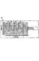
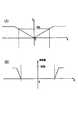
図5に、その一例の時間と振動量のグラフ150が図示されている。周波数が5Hzで振幅値が50%の正弦波152が、装置から出力される所望の振動として示されている(ただし、本図および以下の図では入力出力信号の1秒単位のみを示す)。本発明の制御方法では、波形の各周期の(およその)始点を決め、制御信号154を周期の所定の期間だけ高位つまりオンにする。それ以外の期間では、制御信号154は低位つまりオフとなる。それゆえ、周期制御信号は(指示された)所望の周波数に基づいた振動数をもつ。制御信号154にてアクチュエータを周期毎に1回パルス動作させることにより、所望の振動数の振動がユーザに伝達される。制御信号を高位に立ち上げるのは、図示のように周期の始点でもよいし、周期内の別の時点でも構わない。 FIG. 5 shows a
周期性効果の振動量は、制御信号のデューティサイクル、つまり、制御信号154の各周期の期間(周期のオン期間)を調整することで決定できる。制御信号154は、オンでもオフでもよいが、その信号がオンである周期の時間長は振動量コマンドつまり振動量パラメータで決められる。図5では、振動量50%の正弦波が要求されている。本発明によれば、この要求振動量から、250ms毎に長さが15msの制御信号154が作成される。比較として、同じ周波数の100%振幅波形が図6に図示されており、グラフ154と同様のグラフが160で示されている。制御信号164は、振動数コマンドに変動がないので、制御信号154と同じ間隔で立ち上がっている。しかし、制御信号164は長さが2倍であるので、振動量が2倍の振動をユーザに付与する。制御信号が長くなると、アクチュエータの加速も長くなる。本例では、ERMモータの角速度が大きくなり、作用力が角速度の平方に比例するため、ユーザの手側により大きな作用力が伝わる。好ましくは、質量体の回転を止めずに、回転の開始時にのみ静止摩擦を克服すればよい。制御信号のオン状態が長すぎると、回転する質量体が複数回転してしまい固有(共鳴)振動数に到達する。その時点で、ユーザには指示された振動数ではなくシステム固有振動数が伝達されてしまう。 The amount of vibration of the periodic effect can be determined by adjusting the duty cycle of the control signal, that is, the period of each period of the control signal 154 (period on period). The
それゆえ、本発明では、1)制御信号のオン状態の頻度を振動数コマンドに直接依存させ、2)制御信号のオン期間の長さを振動量コマンドに関連させている。制御信号のオン期間の決定は、異なる方法で実行できる。ここでは2つの方法を述べる。第1に、オン期間は「周期パーセント」で示す。制御信号が各周期で固定パーセントでオンになる場合、振動数が増えるにつれ、周期あたりのオン期間が短くなる。そして、制御信号のオン回数が増える。その結果、制御信号は振動数に関係なく毎秒同じ時間だけ費やすことになる。この方法による長所は、振動数が増えても、一定の電力がアクチュエータに供給されるため、出力される振動量はその振動数範囲において変動しないことである。ただし、オン期間が短くなると、質量体の一方向への回転がとまり、短い駆動時間や重力のため双方向移動を開始し、制御信号がオフになるたびに質量体は反対方向に移動することになる。しかし、これによりユーザへの出力振動に悪い影響を与えることはなく、質量体が完全に一方向に回転したり、双方向移動を行う動作に関係なく、所望の振動数や振動量の振動出力が可能となる。 Therefore, in the present invention, 1) the frequency of the ON state of the control signal directly depends on the frequency command, and 2) the length of the ON period of the control signal is related to the vibration amount command. The determination of the ON period of the control signal can be performed in different ways. Two methods are described here. First, the ON period is indicated by “cycle percentage”. When the control signal is turned on at a fixed percentage in each cycle, the on period per cycle becomes shorter as the frequency increases. And the number of ON times of the control signal increases. As a result, the control signal spends the same amount of time every second regardless of the frequency. The advantage of this method is that even if the frequency increases, a certain amount of power is supplied to the actuator, so that the output vibration amount does not fluctuate in the frequency range. However, when the ON period is shortened, rotation of the mass body in one direction stops and bidirectional movement starts due to short drive time and gravity, and the mass body moves in the opposite direction each time the control signal is turned off. become. However, this does not adversely affect the output vibration to the user, and the vibration output of the desired frequency and vibration amount is possible regardless of the mass body rotating completely in one direction or performing bidirectional movement. Is possible.
図7と8の図は、異なる制御信号とその結果の振動の正弦波を示すグラフ170と180である。図7では、正弦波172の周波数が5Hzで振幅値は100%である。図8では、正弦波182の周波数が10Hzで振幅値が100%である。図7の制御信号174は、各周期にほぼ40msだけオンとなり、図8の制御信号184は、各周期にほぼ20msだけオンとなる。図7と8の両制御信号を比べると、1秒あたりのオン期間は両方とも一定であるが、周波数は変動しており、振動数コマンドが2倍になると、制御信号の周期毎のオン期間が半分となるが、1秒あたりのオン期間は同じで変わらないことが明らかである。 The diagrams of FIGS. 7 and 8 are
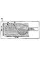
この所望の振動を指示する「周期パーセント」法の問題点は、多くの事例において周波数が低い場合にうまく作用しないことである。低周波数(例えば、ソニーのデュアルショックゲームパッドの大型ERMモータで2Hz未満の場合)、一度に大きな電力がアクチュエータに供給される。例えば、図9のグラフ190では、正弦波192の1秒の期間中に、低振動数(1Hz)で振動量100%の振動が作成されるが、1秒の間に1周期しか振動してない。制御信号194は、周期始点で立ち上げられて125ms継続している。 The problem with the “Percent Percentage” method of indicating this desired vibration is that in many cases it does not work well at low frequencies. At low frequencies (for example, less than 2 Hz with a large ERM motor from Sony's dual shock gamepad), large power is supplied to the actuator at once. For example, in the
図8のグラフ180と図9のグラフ190の両方とも、同じ1秒あたりの時間長分だけ制御信号が高位に変わる。しかしながら、図9では、1秒間の電力が周期始点から連続して125ms入力される。そのオン期間の間、制御信号が高位の間に回転アクチュエータは数回回転するので、125msの振動(パルス)出力は指示振動数ではなくアクチュエータの回転速度の周波数でユーザに伝達される。それゆえ、装置からの振動出力は、指示された(低い)周波数に対応しない。この問題は、図8に示す振動においては顕著ではなく、制御信号184のオン期間が複数期間に分割されているからである。 In both the
本発明の第2の方法では、その低周波数における問題を解決しており、ほとんどの振動装置の振動出力に適切な方法となっている。第2の方法は、周期パーセントではなく、周期あたりの最大固定時間長で制御信号を高位に立ち上げる。そのため、所定周波数における100%振幅値のオン期間は同じとなる。100%未満の指示振幅値のオン期間では、100%以下の指示振幅値に比例して低くなる。これにより、周期あたり最大のオン期間が効果的に設定でき、アクチュエータが連続オン期間で複数回転するくらいの長時間にわたりオンとなるのが防止される。アクチュエータの複数回転が認められる場合(事例では2,3回以上)には、指示周波数(10Hz未満)ではなくアクチュエータの回転速度に基づいた高い周波数(モータにより25Hz程度)がユーザに伝達されることになり、前記の問題をクリアできる。実施例によっては、特定のモータで低い周波数にて振幅値100%が望まれる場合があるが、各周期につき1パルス以上(2,3回転)の振動をユーザに与えるような回転数で質量体を回転駆動させるオン期間と等価であり、オン期間は経験的に決定できる。第2の方法の欠点は、周波数が増えるにつれて、それぞれのオン期間の間隔が接近して、最終的には、アクチュエータが1周期より長い期間オン状態になる。この点で、制御信号が常にオンとなるため、質量体は連続して回転し、振動数や振動量をそれぞれ独立して可変できない。 The second method of the present invention solves the problem at the low frequency, and is suitable for the vibration output of most vibration devices. The second method raises the control signal to a high level with a maximum fixed time length per period, not a period percentage. Therefore, the ON period of the 100% amplitude value at the predetermined frequency is the same. In the ON period of the instruction amplitude value less than 100%, the value decreases in proportion to the instruction amplitude value of 100% or less. Thus, the maximum on period per cycle can be set effectively, and the actuator is prevented from being turned on for a long time such that the actuator rotates a plurality of times during the continuous on period. When multiple rotations of the actuator are recognized (2 or more times in the case), a high frequency (about 25 Hz by the motor) based on the rotation speed of the actuator is transmitted to the user instead of the indicated frequency (less than 10 Hz) The above problem can be cleared. Depending on the embodiment, an amplitude value of 100% may be desired at a low frequency with a specific motor. However, the mass body is rotated at such a rotational speed as to give a vibration of one pulse or more (a few rotations) to each user. Is equivalent to an on period in which the is driven to rotate, and the on period can be determined empirically. The disadvantage of the second method is that as the frequency increases, the intervals of the respective on periods approach each other, and the actuator is finally turned on for a period longer than one cycle. At this point, since the control signal is always on, the mass body rotates continuously, and the frequency and vibration amount cannot be varied independently.
前記の振幅値を制御信号のオン期間にマッピング変換する2つの方法は、周波数帯域の異なる部分でも可能なので、両方法のそれぞれの欠点を解消するため、本発明の好ましい実施例の1つでは両方法を組み合わせ、つまり、合成させている。その組み合わせ方法では、指示周波数が所定の合成閾値より低い場合は第2の方法を利用し、指示周波数が合成閾値より高い場合は第1方法を利用するのである。制御信号の振幅値が可変である場合も、合成は有効である。最初に、合成閾値をシステムのダイナミック値に基づいて選択する。合成周波数は、オン期間が最大長となる周波数であるため、その周波数で振幅値100%に対応するオン期間に周期あたり1振動パルス(質量体回転2回より小さい)を付与できるよう合成周波数を選定する。例えば、上記のような大型モータ/質量体の組み合わせの場合、合成周波数閾値を10Hzに選定する。10Hz以上の指示周波数では、第1の方法(周期パーセント)を使って制御信号のオン期間を算出し、指示周波数が10Hz以下のときは、第2の方法(周期固定時間)を使用する。別の例では、別の閾値を利用できる。2つの方法を合成するには、両方法の最大振幅値が合成周波数閾値に整合するよう、つまり、両方法間の遷移がスムーズとなるようスケールを決定する。例えば、10Hzでの制御信号オン期間を25msにすると、10Hzで100%振幅値の振動が出力できる。指示周波数が10Hz以下から合成周波数値に近似すると、「周期パーセント」法をスケール化して、10Hzで25msのオン期間を算定する。そのスケール処理は、10Hz以上の周波数の方法にも適用可能である。所望の効果を得るためには、合成周波数域における擬似帯域通過フィルター、または、合成閾値の両側でのローパス/ハイパス組み合わせフィルターなどの高度な合成法を利用してもよい。 The two methods for mapping and converting the amplitude value to the ON period of the control signal are possible even in different parts of the frequency band. Therefore, in order to eliminate the disadvantages of both methods, in one of the preferred embodiments of the present invention, both methods are used. The methods are combined, that is, synthesized. In the combination method, the second method is used when the instruction frequency is lower than the predetermined synthesis threshold, and the first method is used when the instruction frequency is higher than the synthesis threshold. The synthesis is also effective when the amplitude value of the control signal is variable. First, a synthesis threshold is selected based on the dynamic value of the system. Since the synthesized frequency is a frequency at which the on period becomes the maximum length, the synthesized frequency is set so that one vibration pulse (less than two mass rotations) can be given to the on period corresponding to the amplitude value of 100% at that frequency. Select. For example, in the case of the large motor / mass combination as described above, the composite frequency threshold is selected to be 10 Hz. For an instruction frequency of 10 Hz or more, the ON period of the control signal is calculated using the first method (period percentage), and when the instruction frequency is 10 Hz or less, the second method (period fixed time) is used. In another example, another threshold can be utilized. In order to combine the two methods, the scale is determined so that the maximum amplitude value of both methods matches the combined frequency threshold, that is, the transition between the two methods is smooth. For example, if the control signal ON period at 10 Hz is set to 25 ms, vibration with a 100% amplitude value can be output at 10 Hz. When the indicated frequency approximates to the synthesized frequency value from 10 Hz or less, the “period percent” method is scaled to calculate an on period of 25 ms at 10 Hz. The scale processing can also be applied to a method having a frequency of 10 Hz or more. In order to obtain a desired effect, an advanced synthesis method such as a pseudo bandpass filter in the synthesis frequency range or a low-pass / high-pass combination filter on both sides of the synthesis threshold may be used.
振動数から独立して振動量を指示する第3の方法では、制御信号に2つのレベルをもたせる代わりに、所要振動量に比例する制御信号の振幅値を可変にする。これにより、前述の第1方法と第2方法の一方または両方の単独または組み合わせて実行できる。例えば、振幅値が可変である別の波形を制御信号(正弦波、三角波など)として利用する。制御信号の振幅値を可変にする効果的な方法として、前述のように制御信号のオン期間中にパルス幅変調(PWM)を行うか、その他の技術を使ってオン期間の制御信号デューティサイクルを可変にする方法がある。しかしながら、PWM法は、装置の価格を押し上げる別途のPWM装置が必要となる。PWM法に代わって、PWM装置を利用せずにアクチュエータに制御信号を供与するローカルマイクロプロセッサを使うビットバング法を利用して第1と第2の方法を実行することも可能である。そのような直接制御は、最新式のフォースフィードバックを利用するさいには実行不能であるが、振動体感フィードバック装置では実現可能である。ビットバング法では、制御信号振幅値を直接に制御することはできないが、PWM装置の必要がなくなり、プロセッサやインターフェイス装置のコストを下げることが可能となる。 In the third method of instructing the vibration amount independently of the frequency, the amplitude value of the control signal proportional to the required vibration amount is made variable instead of giving the control signal two levels. Accordingly, one or both of the first method and the second method described above can be executed alone or in combination. For example, another waveform having a variable amplitude value is used as a control signal (sine wave, triangular wave, etc.). As an effective method of making the amplitude value of the control signal variable, pulse width modulation (PWM) is performed during the ON period of the control signal as described above, or the control signal duty cycle of the ON period is changed using other techniques. There is a way to make it variable. However, the PWM method requires a separate PWM device that increases the price of the device. In place of the PWM method, the first and second methods can be executed by using a bit-bang method using a local microprocessor that supplies a control signal to the actuator without using a PWM device. Such direct control is not feasible when using state-of-the-art force feedback, but is feasible with a vibration sensation feedback device. In the bit bang method, the control signal amplitude value cannot be directly controlled, but the need for the PWM device is eliminated, and the cost of the processor and the interface device can be reduced.
前記の振動の振動量や振動数をそれぞれ独立して可変にする方法は、単一または複数のアクチュエータに同時に適用可能である。アクチュエータが複数の場合、モータ/質量体の組み合わせを共同作用させて、全振動帯域を可能にする。このことは、オーディオ用スピーカのウーファとツイータの組み合わせと同じである。例えば、ソニーのデュアルショックゲームパッドは2個のモータを備えるため、本発明の方法を利用すれば、100Hzのダイナミックレンジが達成できる。一例として、大型モータ/質量体の組み合わせにおいて、合成閾値が10Hzの所定周波数帯域で両方の制御方法を利用できる。小型モータ/質量体の組み合わせでは、第2の方法(周期固定時間)のみを使って、(第2方法では、オン期間が周波数低下に伴って短くなることがないので)増加周波数で小型モータに電力供給するのである。そのため、大型モータの大きな振幅値振動が小型モータの高周波数の低振動を打ち消す傾向が排除できる。しかも、フィルターを利用すれば、一定周波数帯域での大型モータと小型モータのバランスを適切値にできる。 The method of making the vibration amount and frequency of the vibrations independently variable can be applied simultaneously to a single or a plurality of actuators. In the case of multiple actuators, the motor / mass combination is combined to allow the full vibration band. This is the same as the combination of the audio speaker woofer and tweeter. For example, Sony's dual-shock gamepad has two motors, so a 100 Hz dynamic range can be achieved using the method of the present invention. As an example, in a large motor / mass combination, both control methods can be used in a predetermined frequency band with a synthesis threshold of 10 Hz. In the small motor / mass combination, only the second method (period fixed time) is used, and in the second method, the on-period is not shortened as the frequency decreases, so that the small motor can be increased at an increased frequency. Power is supplied. Therefore, the tendency that the large amplitude vibration of the large motor cancels the high frequency low vibration of the small motor can be eliminated. In addition, if a filter is used, the balance between the large motor and the small motor in a certain frequency band can be set to an appropriate value.
5Vを使う例においては、小型モータの出力は小さく、ユーザが振動を感じえないくらいである。そこで、装置の最大許容周波数を25Hzに設定して、適当なスケール化を行うことにより、周波数のダイナミックレンジを25Hz程度に狭くする。これにより、大型モータを使って振動効果全部を実行できるため、小型モータが必要なくなる。5Vバッテリーを採用すれば、小型ERMモータをより適度なサイズに変更でき、大きな振動が出力できる。 In the example using 5V, the output of the small motor is small and the user cannot feel the vibration. Therefore, by setting the maximum allowable frequency of the apparatus to 25 Hz and performing appropriate scaling, the frequency dynamic range is narrowed to about 25 Hz. As a result, since the entire vibration effect can be executed using a large motor, a small motor is not necessary. If a 5V battery is adopted, the small ERM motor can be changed to a more appropriate size, and a large vibration can be output.
別の例として、上記の方法ではなく、より単純な制御方法で、周期性効果を得ることも可能である。指示振動量を無視して、振動数コマンドのみを利用する。例えば、2個モータ式の振動体感装置では、所定の閾値周波数を使って、出力振動にどのモータを利用するかを決定する。15Hzを越える振動の場合、小型モータ/質量体を回転駆動させる。小型モータ/質量体は、指示振動数に比例する周波数で駆動する、または、所定の周波数で回転させる。この効果は、ドライブゲームでの自動車のエンジンのイベントとして利用できる。15Hz以下の振動の場合、大型モータ/質量体を所定の周波数、または、指示振動数に比例する周波数(指示振動数をスケール化して大型モータの帯域の周波数値にする)で回転駆動させる。この効果は、ゲームにおけるでこぼこの地面の移動や衝突に利用できる。 As another example, it is possible to obtain a periodic effect by a simpler control method instead of the above method. Ignore the indicated vibration amount and use only the frequency command. For example, in a two-motor type vibration sensation apparatus, a predetermined threshold frequency is used to determine which motor is used for output vibration. In the case of vibration exceeding 15 Hz, the small motor / mass body is driven to rotate. The small motor / mass body is driven at a frequency proportional to the indicated frequency or rotated at a predetermined frequency. This effect can be used as a car engine event in a drive game. In the case of vibrations of 15 Hz or less, the large motor / mass body is rotated at a predetermined frequency or a frequency proportional to the indicated frequency (the indicated frequency is scaled to a frequency value in the large motor band). This effect can be used for bumpy ground movements and collisions in games.
振動体感装置の非周期性効果の制御
上記の方法は、ERMモータで周期性作用力効果を出力するのに使われている。その他、いくつかの状態効果を含む非周期性の運動感覚効果をマッピング処理して、振動体感装置で出力できる振動体感効果に変換するのにも利用できる。Control of non-periodic effect of vibratory sensation apparatus The above method is used to output a periodic action force effect by an ERM motor. In addition, a non-periodic kinesthetic effect including several state effects can be mapped and converted into a vibration sensation effect that can be output by the vibration sensation apparatus.
非周期性効果は、非同期の振動量パラメータ、それ以外のパラメータ、それらパラメータの組み合わせに基づいて決定することができる。非周期性効果は、周期性効果のように簡単に振動体感効果にマッピング変換することができない。例えば、ベクトル作用力は、所定の時間長に所定方向に出力される非周期性効果である。一般的に振動体感装置は所定方向に作用力を出力できないため、ベクトル作用力を振動体感作用力刺激にマッピング変換する処理は周期性効果ほど直接的にはできない。 The non-periodic effect can be determined based on an asynchronous vibration amount parameter, other parameters, or a combination of these parameters. The non-periodic effect cannot be mapped and converted to the vibration sensation effect as easily as the periodic effect. For example, the vector acting force is an aperiodic effect that is output in a predetermined direction for a predetermined time length. In general, since the vibration sensation apparatus cannot output an acting force in a predetermined direction, the process of mapping the vector acting force to the vibration sensation acting force stimulus cannot be performed as directly as the periodic effect.
非周期性の運動感覚効果のいくつかは、条件である。「条件」とは、振動や揺動などの開ループ効果とは逆の、より高度な運動感覚性フォースフィードバック装置にて出力される閉ループフォースフィードバック効果である。条件効果は、その出力サイズを決定する際、(運転ハンドル、ジョイスティック、マウスなどの)ユーザ操作具の位置データおよび/または速度データ(および/または加速データ)を必要とする。例えば、バネ条件効果は、ユーザ操作具の現在位置に依存し、ダンパー条件効果は、ユーザ操作具の現在速度に依存するのである。 Some of the non-periodic kinesthetic effects are conditions. “Condition” is a closed-loop force feedback effect output by a more advanced kinesthetic force feedback device, which is opposite to an open-loop effect such as vibration or swing. Conditional effects require position data and / or speed data (and / or acceleration data) of user controls (such as driving handles, joysticks, mice, etc.) in determining their output size. For example, the spring condition effect depends on the current position of the user operation tool, and the damper condition effect depends on the current speed of the user operation tool.
多くの場合、操作具を移動させてその自由度内で作用力を発生させるようなフォースフィードバック(運動感覚性)装置に対して、それら条件は応用できる。単一の振動体感フィードバック装置で表現する場合、それら条件は変換自在である。 In many cases, these conditions can be applied to a force feedback (motor sensory) device that moves an operating tool and generates an acting force within the degree of freedom. When expressed by a single vibratory sensation feedback device, these conditions can be freely changed.
一例として、条件を無視すると、アプリケーションプログラムで条件作用力の出力をコマンド指示する場合、振動体感装置のローカルマイクロプロセッサ(または、ホストコンピュータのドライバーやその他プログラム)がそのコマンドを無視するので、作用力が出力されない。しかしながら、別の例では、条件はマッピング処理されて振動体感刺激に変換され、条件作用力効果を近似する、または、イベントを特定する少なくともいくつかのフォースフィードバックをユーザに体験させることができる。非周期性作用力効果のマッピング処理の例を、以下に説明する。 As an example, if the condition is ignored and the application program issues a command to output the conditional action force, the local microprocessor of the vibration sensation device (or the host computer driver or other program) ignores the command. Is not output. However, in another example, the condition can be mapped and converted to a vibratory sensation stimulus, allowing the user to experience at least some force feedback that approximates a conditioned effect or identifies an event. An example of the mapping process of the non-periodic force effect will be described below.
ベクトル作用力
ベクトル作用力は、操作具の1つまたは複数の自由度において所定の方向へ作用力を付与する運動感覚性作用力効果である。例えば、レースや運転ゲームでは、自動車が壁や他の自動車などの障害物に衝突したときに運転ハンドルの回転に衝突刺激、操作具を動かすときのシフト刺激、自動車が制御不能になったときのスピン刺激などを出力するのにベクトル作用力が使われている。ベクトル作用力の大きさは、イベントや他の要素の衝撃度によって異なる。Vector action force Vector action force is a kinematic sensory action effect that imparts an action force in a predetermined direction in one or more degrees of freedom of the operating tool. For example, in a racing or driving game, when a car collides with an obstacle such as a wall or another car, a collision stimulus is applied to the rotation of the driving handle, a shift stimulus is used to move an operation tool, or the car is out of control. Vector force is used to output spin stimuli. The magnitude of the vector acting force varies depending on the event and the impact level of other elements.
ほとんどの振動体感装置において、一般的に指向性作用力は出力されず、振動や揺動を使って近似する必要がある。けれども、振動体感装置からの揺動や振動出力は、ベクトル作用力と同じである。好ましくは、振動は高振動数で高振動量の出力であり、例えば、1秒間に1Hzの周波数を与えて単一の揺動を出力させて1つの振動を発生させる。別の例では、振動体感装置では所定のベクトル作用力のコマンドが無視される。例えば、ドライブゲームにおいて、低振動量のベクトル作用力は、振動体感効果で簡単に模倣できないごく小さな駆動力を出力するのによく利用されるため、振動体感装置で無視されることがある。2個のモータを備える振動体感ゲームパッド装置では、大型モータを回転させてベクトル作用力に応じた振動を発生させるか、または、両方のモータを回転させる。 In most vibration sensation devices, generally no directional acting force is output, and it is necessary to approximate them using vibration and oscillation. However, the swing and vibration output from the vibration sensation apparatus are the same as the vector acting force. Preferably, the vibration is an output with a high frequency and a high vibration amount. For example, a single vibration is generated by applying a frequency of 1 Hz per second to generate one vibration. In another example, a predetermined vector acting force command is ignored in the vibration sensation apparatus. For example, in a drive game, a vector action force with a low vibration amount is often used to output a very small driving force that cannot be easily imitated by a vibration experience effect, and may be ignored by the vibration experience device. In the vibration sensation game pad device including two motors, a large motor is rotated to generate vibration according to the vector acting force, or both motors are rotated.
別の好ましい実施例として、ベクトル作用力を直接に振動へとマッピング変換し、結果たる振動の振動量がベクトル作用力の振幅値に比例する。振動量は、周期性作用力に関して上記で説明した方法を使って独立して制御するのが好ましい。振動量は、ベクトル作用力コマンドの振動量パラメータに比例するか、または、それを基に決定される。振動の振動数は、所定値である一定周波数であって、例えば、固定周波数を装置が出力できる最大振動数にすることが可能である。別の実施例として、ベクトル作用力の振動数をユーザが選択可能にしても構わない。 As another preferred embodiment, the vector acting force is directly mapped and converted into vibration, and the vibration amount of the resulting vibration is proportional to the amplitude value of the vector acting force. The amount of vibration is preferably controlled independently using the method described above with respect to the periodic acting force. The vibration amount is proportional to or determined based on the vibration amount parameter of the vector acting force command. The frequency of the vibration is a constant frequency that is a predetermined value, and for example, the fixed frequency can be set to the maximum frequency that the apparatus can output. As another example, the frequency of the vector acting force may be selectable by the user.
ベクトル作用力を振動に変換する別の方法では、ベクトル作用力振動量をモータコマンドに直接にマッピング変換し、つまり、デューティサイクルで示すベクトル作用力の振動量をコマンドとして利用してモータを回転させるもので、50%振幅値を50%のディーティサイクルモータコマンドとする。これにより、作用力のパルスをベクトル作用力の代替に使用できる。別の例では、運動感覚性ベクトル作用力振動量コマンドを全帯域のモータ振幅値コマンドにマッピング変換する代わり、ベクトル作用力振動量をモータ振幅値コマンド範囲の上半分にマッピング変換することも可能である。そのため、つねに質量体の全回転させるような高い振動量を出力させることができ、出力応答をより線形にすることが可能となる。また別の例では、振幅値コマンド範囲の下部分を使って、高調波質量体移動を可能にしている。 In another method of converting vector acting force into vibration, the vector acting force vibration amount is directly mapped to a motor command, that is, the motor is rotated using the vibration amount of the vector acting force indicated by the duty cycle as a command. Therefore, a 50% amplitude value is a 50% duty cycle motor command. Thereby, the pulse of the acting force can be used as a substitute for the vector acting force. As another example, instead of mapping the kinematic sensory vector acting force vibration amount command to the motor amplitude value command of the entire band, it is also possible to map the vector acting force vibration amount to the upper half of the motor amplitude value command range. is there. For this reason, it is possible to always output a high vibration amount that causes the mass body to fully rotate, and to make the output response more linear. In another example, the lower portion of the amplitude value command range is used to enable harmonic mass transfer.
もっと簡単な例では、要求される振動量の振幅値閾値を使って、複数のモータを備えた装置のベクトル作用力を近似する時点や方法を決定する。例えば、第1の閾値は振幅値が75%(出力できる最大振動量の75%)のとき与えられる。小型モータと大型モータを備えた装置では、ベクトル作用力が0%より75%の間のとき、大型モータを駆動制御して、指示ベクトル作用力振幅値に比例する振動量の振動(1揺動)を出力させる。指示ベクトル作用力の振動量が最大100%の76%である場合、大型モータと小型モータの両方を駆動して、最大振動量の振動力を発生させる。注意してもらいたいのは、前述のような閾値を前記方法に併用することにより、所定閾値内での振動の振動量と振動数とをそれぞれ独立して制御することである。そのような合成方法は、説明するあらゆる種類の作用力効果に応用できる。 In a simpler example, the time point and method of approximating the vector acting force of a device having a plurality of motors are determined by using the amplitude value threshold value of the required vibration amount. For example, the first threshold value is given when the amplitude value is 75% (75% of the maximum vibration amount that can be output). In a device having a small motor and a large motor, when the vector acting force is between 0% and 75%, the large motor is driven and controlled, and the vibration of the amount of vibration proportional to the instruction vector acting force amplitude value (one swing) ) Is output. When the vibration amount of the instruction vector acting force is 76%, which is 100% at the maximum, both the large motor and the small motor are driven to generate the vibration force having the maximum vibration amount. It should be noted that the vibration amount and the vibration frequency within the predetermined threshold value are controlled independently by using the above-described threshold value in combination with the above method. Such a synthesis method can be applied to all kinds of acting effects described.
ベクトル作用力へのマッピング処理も、(実施例として)アプリケーションコマンドつまり目標コマンドに基づいて選択的に適用可能である。例えば、ゲームで発生する衝突のためベクトル作用力が出力されるような場合、等価な振動力を利用できる。しかし、ベクトル作用力が運転ターン時にハンドルを戻すダイナミックバネをシミュレートするのに使われる場合は、振動力は適用できない。 The mapping process to the vector acting force can also be selectively applied based on an application command, that is, a target command (as an example). For example, when a vector action force is output due to a collision occurring in a game, an equivalent vibration force can be used. However, if vector acting force is used to simulate a dynamic spring that returns the steering wheel during a driving turn, vibration force is not applicable.
別の振動体感装置では、指向性作用力を出力することも可能である。例えば、回転または移動する質量体を回転制御して、質量体の自由度の所定方向に指向性作用力を近似できる。複数のモータを備える装置では、互いに同相となるようモータを制御して、所定方向の作用力を発生させることができる。別の例として、ベクトル作用力の方向または近似の方向に作用力を出力させる場合、ベクトル作用力を振動体感装置での指向性作用力となるようマッピング変換することも可能である。 In another vibration sensation apparatus, it is also possible to output directivity acting force. For example, by rotating the mass body that rotates or moves, the directivity acting force can be approximated in a predetermined direction of the freedom degree of the mass body. In an apparatus including a plurality of motors, it is possible to generate an acting force in a predetermined direction by controlling the motors to be in phase with each other. As another example, when the acting force is output in the direction of the vector acting force or an approximate direction, the vector acting force can be subjected to mapping conversion so as to become the direct acting force in the vibration sensation apparatus.
バネ作用力
バネ作用力は、演算式F=kXに基づく状態であって、出力Fは、kが定数で、所定自由度でのユーザ操作具の現在位置Xに基づくものであることを示している。例えば、運転ゲームにおいて、バネ作用力は運転ハンドルを中央位置に戻すため使われ、その中央位置からの、かつ、中央位置に向かう方向へのハンドルの回転量に比例する振動量の作用力をユーザが感知することになる。Spring acting force The spring acting force is a state based on the arithmetic expression F = kX, and the output F indicates that k is a constant and is based on the current position X of the user operation tool at a predetermined degree of freedom. Yes. For example, in a driving game, the spring acting force is used to return the driving handle to the center position, and the user exerts an acting force with a vibration amount proportional to the amount of rotation of the handle from the center position toward the center position. Will sense.
バネ運動感覚作用力を振動作用力効果にマッピング変換するとき、異なる方法が適用できる。一例として、バネ作用力は振動や揺動で模倣できないため、振動体感装置でバネコマンドが無視される場合がある。例えば、一定の自由度でユーザの操作具を中央位置に戻す場合、その環境下では振動や揺動はユーザに注目を向けさせないため、バネ作用力はしばしば無視されてしまう。 Different methods can be applied when mapping the spring kinematic sensory action force to the vibration action force effect. As an example, since the spring acting force cannot be imitated by vibration or swinging, the spring command may be ignored by the vibration sensation apparatus. For example, when the user's operation tool is returned to the central position with a certain degree of freedom, the spring acting force is often ignored because vibration and swinging do not direct the user's attention in that environment.
別の例、つまり別の環境では、振動作用力がバネ作用力として出力される。例えば、自動車の運転中にターンをすると、中央位置戻りバネ作用力により運転ハンドルを中央位置へ戻されるよう動作する。この効果を運動感覚装置でシミュレートするために、バネ作用力を出力させるのである。振動体感装置では、振動が出力される。 In another example, that is, in another environment, the vibration acting force is output as a spring acting force. For example, when a turn is made during driving of an automobile, the driving handle is moved back to the central position by the central position return spring acting force. In order to simulate this effect with a kinesthetic device, a spring acting force is output. In the vibration sensation apparatus, vibration is output.
図10(A)と10(B)に、その例を示す。図10(A)は、運動感覚性のフォースフィードバック装置での一般的なバネ作用力出力を示すグラフであり、原点OからX軸に沿った操作具の移動により、その移動量につれて増える振動量をもつ動きに抵抗するバネ作用力を出力させている。図10(B)は、振動体感効果へマッピング変換する例を示す。75%などの所定のバネコマンド振幅値閾値より大きい振動が出力されるが、その振動数は固定値(またはユーザ選択値)である。それゆえ、高振動量バネコマンドだけで振動を出力する。ゲームパッドのジョイスティックなどの操作具を備える振動体感装置では、図10(A)のバネ作用力の75%またはそれ以上の振動量に応じた操作具位置(X軸)でのみ振動が出力される。閾値よりも大きなコマンド振動量では、図に示すように、バネ振動量コマンドに比例した段階率にて振動量が最大値まで増加している。この効果は、自動車の高速ターンにおける運転ハンドルのブレやユレをシミュレートするのに利用できるので、バネ作用力効果を直接シミュレートせず、異なる効果をバネ作用力効果の代替として出力する。別の例では、(ユーザ操作具の位置によって異なる)バネコマンドの振動量から振動が出力される。 An example is shown in FIGS. 10 (A) and 10 (B). FIG. 10A is a graph showing a general spring action force output in the kinematic force feedback device, and the amount of vibration that increases with the amount of movement of the operating tool along the X axis from the origin O. The spring acting force that resists the movement with is output. FIG. 10B shows an example of mapping conversion to the vibration sensation effect. A vibration larger than a predetermined spring command amplitude value threshold value such as 75% is output, but the vibration frequency is a fixed value (or a user-selected value). Therefore, vibration is output only with a high vibration amount spring command. In the vibration sensation apparatus having an operation tool such as a joystick for a game pad, vibration is output only at the operation tool position (X axis) corresponding to the vibration amount of 75% or more of the spring acting force in FIG. . When the command vibration amount is larger than the threshold, the vibration amount increases to the maximum value at a step rate proportional to the spring vibration amount command, as shown in the figure. Since this effect can be used to simulate the blurring or swaying of the steering wheel in a high-speed turn of an automobile, the spring acting force effect is not directly simulated, and a different effect is output as an alternative to the spring acting force effect. In another example, the vibration is output from the vibration amount of the spring command (which varies depending on the position of the user operation tool).
バネ効果(または、ダンパー効果など)は、小型モータなどの1個のモータで前述のようにベクトル作用力として出力できる。これは、ジョイスティック位置をフィードバックできるため、ゲームをするユーザにとっては都合がよいが、興味を示さないユーザもいる。そこで、条件作用力をERM駆動振動体感コントローラで出力する場合には、ホストコンピュータのアプリケーションレイヤまたはソフトウェアレイヤで提供されるプロフィラプログラムにて、停止させたり変更させたりできる選択をユーザに与えるのが好ましい。 The spring effect (or the damper effect or the like) can be output as a vector acting force as described above by one motor such as a small motor. This is convenient for the user who plays the game because the joystick position can be fed back, but there are some users who are not interested. Therefore, when the condition action force is output by the ERM drive vibration sensation controller, the profiler program provided in the application layer or software layer of the host computer is given to the user a choice that can be stopped or changed. preferable.
障害作用力
壁などの障害も、バネ作用力を使って位置制御アプリケーションのフォースフィードバックでシミュレートできる。振動体感アプリケーションにおいて、壁やその他の障害の出現は、揺動つまり低周波数振動を使ってシミュレートする。好ましくは、最初に壁との衝突が発生したとき、最大振動量に近い作用力を出力する。最初の衝突の後、ユーザが制御するグラフィック上物体(カーソル、自動車など)が壁との接触を継続する場合には、振動も継続させる。または、前述した周期効果の方法を使って振動を実質的にゼロ振動量まで低下させる。そのような制御方法は、振動の振動量を徐々に低下させるなどの、周期波形に応用されるエンビロープと共同作用できる。アタックパラメータやフェードパラメータを使う周期性効果利用は、米国特許第5,959,613に詳細に記述されている。Obstacles such asobstacle action walls can be simulated with force feedback in position control applications using spring action forces. In vibration experience applications, the appearance of walls and other obstacles is simulated using rocking or low frequency vibration. Preferably, when the first collision with the wall occurs, an acting force close to the maximum vibration amount is output. If the graphical object (cursor, car, etc.) controlled by the user continues to contact the wall after the first collision, the vibration is also continued. Alternatively, the vibration is reduced to substantially zero vibration amount by using the above-described periodic effect method. Such a control method can cooperate with an envelope applied to a periodic waveform, such as gradually reducing the amount of vibration. The use of periodic effects using attack and fade parameters is described in detail in US Pat. No. 5,959,613.
ダンパー作用力
ダンパー作用力は、一般的に演算式F=Bvで示す条件作用力であって、作用力Fは、所定の自由度でのユーザ操作具の現在速度vとダンパー定数Bで表すことができる。この作用力は、移動するときにユーザ作用具に抵抗力をかけるもので、移動速度が早いほど大きな抵抗力が出力される。例えば、運転ゲームでは、制御される自動車がオイルや水たまりに突っ込むと運転ハンドルにダンパー作用力が出力されて、液体内でのハンドル操作の減衰をシミュレートするものである。Damper acting force The damper acting force is generally a condition acting force represented by an arithmetic expression F = Bv, and the acting force F is represented by the current speed v of the user operation tool and a damper constant B with a predetermined degree of freedom. Can do. This action force applies a resistance force to the user action tool when moving, and a greater resistance force is output as the moving speed increases. For example, in a driving game, a damper acting force is output to a driving handle when a controlled vehicle rushes into oil or a puddle, simulating the attenuation of the steering operation in the liquid.
振動体感装置では、ダンパー作用力は高周波数振動にマッピング変換される。例えば、2個モータ駆動装置では、小型モータ/質量体を制御して、運転ゲームのユーザに対して地面の変化を示すときなど、わずかな角回転つまり低振動量を出力する。これにより、自動車が液体に突っ込んだときなどの「ぬかるみ状態」の振動効果をシミュレートすることができる。別の例として、制御対象物(自動車やカーソル)の現在速度に比例、または、小型ジョイスティックなどのユーザ操作具の現在速度に比例する振動量の振動に、ダンパー作用力をマッピング変換することも可能である。振動体感の振動量は、周期性効果で説明した方法で実現できる。別の例では、振動体感装置でダンパー作用力が無視される。例えば、ダンパー作用力がゲーム中のユーザに大きな規制を与えるような場合、振動による制御制限を避けるため、振動出力を止めるのがよい。 In the vibration sensation apparatus, the damper acting force is mapping-converted to high frequency vibration. For example, in a two-motor drive device, a small motor / mass body is controlled to output a slight angular rotation, that is, a low vibration amount, when a change in the ground is shown to a user of a driving game. As a result, it is possible to simulate the “slack state” vibration effect such as when an automobile rushes into the liquid. As another example, it is also possible to map the damper action force to vibration of the amount of vibration proportional to the current speed of the control object (car or cursor) or proportional to the current speed of the user operation tool such as a small joystick. It is. The vibration amount of the vibration sensation can be realized by the method described in the periodic effect. In another example, the damper acting force is ignored in the vibration sensation apparatus. For example, when the damper acting force gives a large restriction to the user in the game, it is preferable to stop the vibration output in order to avoid control restriction due to vibration.
別のタイプの運動感覚性作用力効果も、前述したのと同様の方法で振動体感効果にマッピング変換できる。例えば、摩擦作用力は、制御するグラフィック上物体の速度、つまり、ユーザの操作対象物の速度と相関関係のある振動量をもつ高周波数振動を使ってマッピング処理する。テキスチャ作用力は、特定の位置で揺動を発生する特徴をもつテキスチャ面における操作具の移動に基づいた揺動、衝撃、その他作用力をユーザに与えるものである。そのようなテキスチャ作用力は、ユーザがテキスチャ面と接触する率にほぼ対応した周波数のERMモータからの出力振動によりシミュレートできる。 Another type of kinematic sensory force effect can be mapped and converted to a vibration sensation effect in the same manner as described above. For example, the frictional action force is mapped using high-frequency vibration having a vibration amount correlated with the speed of the graphic object to be controlled, that is, the speed of the user's operation target. The texture acting force gives the user rocking, impact, and other acting force based on the movement of the operation tool on the texture surface having the characteristic of generating rocking at a specific position. Such a texture acting force can be simulated by an output vibration from an ERM motor having a frequency substantially corresponding to the rate at which the user contacts the texture surface.
簡単にいえば、振動体感装置をアプリケーション全特性の作用力コマンドに対応させるため、運動感覚性効果と振動体感効果間のマッピング処理を行うのである。単指向性回転する簡単なERMモータで周期性効果を出力させるため、振動量と振動数をそれぞれ独立して可変できる新規の方法を説明する。別のマッピング処理でも、運動感覚性効果を振動体感効果に変えられる。1つの解決方法は、低価格の振動体感装置で少なくとも1つの集合の運動感覚性作用力を出力させることである。条件効果や運動感覚作用力効果は、効果性が低く、全部の低価格振動体感装置で実現できるものではないが、多くの運動感覚性フィードバック装置で簡単に出力可能であるため、多様な製品を市場に提供できる。そのため、ユーザは、体感フィードバックインターフェイス装置にどれくらいお金を費やすかによって、必要とする体感フィードアック機能性や洗練性を選択することができるのである。 In short, in order to make the vibration sensation apparatus respond to the action command of all the characteristics of the application, a mapping process between the kinematic effect and the vibration sensation effect is performed. In order to output a periodic effect with a simple ERM motor that rotates unidirectionally, a novel method is described in which the amount of vibration and frequency can be varied independently. In another mapping process, the kinematic effect can be changed to the vibration effect. One solution is to output at least one set of kinematic sensory forces with a low-cost vibration sensation device. Conditional effects and kinesthetic sensory effects are not effective and cannot be realized with all low-cost vibration sensation devices, but can be easily output with many kinesthetic feedback devices, so a variety of products are available. Can be offered to the market. Therefore, the user can select the necessary experience feedback functionality and sophistication according to how much money is spent on the experience feedback interface device.
ERMモータを使う一定作用力効果
図4に示すハードウェアトポロジーは、上記で説明した全部の制御装置に適用できる。一例として、モータの位置に関するホストコンピュータやローカルマイクロプロセッサへのセンサーフィードバックがなく、つまり、システムが開ループの場合がある。上記の制御方法は、モータ位置に関するフィードバックの必要がない。コントローラへモータ位置を知らせる特定のセンサーを必要としないため、開ループシステムによりインターフェイス装置が低価格になる。Constant Working Force Effect Using ERM Motor The hardware topology shown in FIG. 4 can be applied to all the control devices described above. As an example, there is no sensor feedback to the host computer or local microprocessor regarding the position of the motor, i.e. the system is open loop. The above control method does not require feedback regarding the motor position. An open loop system makes the interface device less expensive because it does not require a specific sensor to inform the controller of the motor position.
しかしながら、フィードバック制御ループを閉にするセンサーがないと、信頼性に問題が起こる。例えば、ERMモータが必要なとき確実に回転していることを判断するのが困難となる恐れがある。振動量/振動数の組み合わせをコマンド出力して、モータを始動させるが、実際には、モータがすでに回転している場合にのみモータを回転させる。また、ユーザがインターフェイス装置や操作具をゆすったり、叩いたり、傾けたりすると、モータが回転しない。または、ユーザがインターフェイス装置を、重力がERM要素以下となるような特定の姿勢で把持する場合にだけ、モータを回転させる。このため、同じコマンドの作用力効果でも、コントローラ、ERMモータ、その他の条件などによってユーザは異なる体感を経験する。多くのアプリケーションで、そのような状態は不都合であり、装置がどのように把持されようとどのような位置にあろうと、アプリケーションプログラムや別のコントローラでコマンド制御される場合は常に作用力効果が一定でなければならない。 However, without a sensor that closes the feedback control loop, reliability issues arise. For example, it may be difficult to determine that the ERM motor is reliably rotating when necessary. The motor is started by outputting the vibration amount / frequency combination as a command, but actually the motor is rotated only when the motor is already rotating. Further, when the user shakes, strikes, or tilts the interface device or operation tool, the motor does not rotate. Alternatively, the motor is rotated only when the user holds the interface device in a specific posture such that gravity is equal to or less than the ERM element. For this reason, the user experiences different sensations according to the controller, the ERM motor, and other conditions even with the same command effect. For many applications, such a situation is inconvenient and the force effect is always constant when commanded by an application program or another controller, no matter how the device is gripped or in any position. Must.
質量体が必要なときに確実に回転させて一定の作用力を供与するための方法は、システムダイナミック特性をモデル化することである。この方法では、フィードバックセンサーを必要とせず、物理的システムのモデルを予め作成して、ERMモータの状態を予測するのに利用するのである。予測情報は、ERMモータが始動し連続運転するさい、ERM特性を上げるのに使う。もっと簡単に実行できる方法は、モータを始動するコマンド作用力刺激の開始周期に最大振幅値でモータを回転させるよう制御することである。これにより、インターフェイス装置の姿勢からERMモータが大きな重力に対向して駆動する状況などの不都合な場合であっても、モータの動作を一定に維持できる。そのような不都合な場合、ERMモータをひとたび駆動すると、ERMモータは強制的に回転させられて、指示された効果がより容易く出力できる。好ましくは、最大回転値の開始周期が、前述の周期性作用力効果用の「固定期間」方法により行われるのがよい。振動の第1周期の後、所定の振動量と振動数を示すコマンドパラメータに戻る(振動数が低い場合、「固定期間」方法の利用を継続する)。本実施例ではセンサーやフィードバックループの必要がないので、装置の価格を下げられる。 A way to ensure that the mass is rotated to provide a constant force when needed is to model the system dynamic characteristics. In this method, a feedback sensor is not required, and a physical system model is created in advance and used to predict the state of the ERM motor. The prediction information is used to improve the ERM characteristics when the ERM motor is started and continuously operated. A method that can be performed more simply is to control the motor to rotate at the maximum amplitude value during the start period of the command force stimulus that starts the motor. Thereby, even if it is inconvenient such as a situation where the ERM motor is driven to face a large gravity from the attitude of the interface device, the operation of the motor can be kept constant. In such an inconvenience, once the ERM motor is driven, the ERM motor is forced to rotate and the indicated effect can be more easily output. Preferably, the start cycle of the maximum rotation value is performed by the above-described “fixed period” method for the periodic acting force effect. After the first period of vibration, return to the command parameter indicating the predetermined amount and frequency (if the frequency is low, continue to use the “fixed period” method). In this embodiment, there is no need for a sensor or a feedback loop, so that the price of the apparatus can be reduced.
別の例では、モータが中断しており、回転続行が必要な場合、モータの電圧を測定し、ローカルプロセッサのA/D変換器にフィードバックさせる。この信号は、モータが停止しているかどうかを示すものである。フィードバックループは、製品コストを増加させることなく、電力要求を満たす支援を行う。 In another example, if the motor is interrupted and rotation needs to continue, the motor voltage is measured and fed back to the local processor A / D converter. This signal indicates whether the motor is stopped. The feedback loop assists in meeting power requirements without increasing product costs.
またフィードバックセンサーを使用することなく所望の動作を確実にする別の方法として、振動数/振動量の全範囲におけるモータ動作を予め定量しておいて、動作中にカウンタをモニターする方法もある。体感効果によりモータが全回転しカウンタが「最大値」(カウンタの最大カウント値)以下のときは、カウンタをカウントアップさせて要求される制御信号を出力する。体感効果がモータ動作を必要としないが(経験的に判断する)、カウンタが0以上で、モータ回転を希望するような場合、カウンタをカウントダウンさせて、要求される制御信号を出力する。体感効果が(振動量と振動数をもつ)モータ駆動が要求されるが、回転を開始するための開始エネルギー値に到達しない状態で、カウンターが「最大値」以下の場合には、カウンタをカウントアップする。要求される制御信号は出力されないが、最大振幅値制御信号が出力される。体感効果が同じ状態でカウンタが「最大値」である場合、要求される制御信号が出力されるのである。 As another method for ensuring a desired operation without using a feedback sensor, there is a method in which the motor operation in the entire range of vibration frequency / vibration amount is quantified in advance and a counter is monitored during the operation. When the motor is fully rotated by the bodily sensation effect and the counter is equal to or less than the “maximum value” (maximum count value of the counter), the counter is counted up and the required control signal is output. If the sensory effect does not require motor operation (determined empirically), but the counter is 0 or more and motor rotation is desired, the counter is counted down and the required control signal is output. The motor is required to have a sensation effect (with vibration amount and frequency), but if the counter does not reach the starting energy value to start rotation and the counter is below the “maximum value”, the counter is counted. Up. The required control signal is not output, but the maximum amplitude value control signal is output. When the counter is “maximum value” with the same sensation effect, the required control signal is output.
最後に、別の例として、低価格仕様をゆるめて、モータの位置および/または回転を検出するセンサーを装備する。センサーのもっとも重要な利用法は、アクチュエータのフィードバックループを閉にして、確実にアクチュエータを適切動作(振動または回転)させることである。モータ主軸上に取りつけた1/4エンコーダをセンサー代わりに利用できるが、その価格や高度機能性は本適用例には過ぎるものである。別の例として、簡単なブール式センサー、ERMモータでブロックするIRセンサー、鋼鉄製や金属製のERMモータに磁束をかけるホール効果センサーなども利用可能である。これら簡単なセンサーでも、質量体がフル回転しているかどうかをローカルマイクロプロセッサに通知できる。 Finally, as another example, the low-cost specification is loosened and equipped with sensors that detect motor position and / or rotation. The most important use of the sensor is to close the actuator feedback loop to ensure proper operation (vibration or rotation) of the actuator. Although a 1/4 encoder mounted on the motor spindle can be used instead of a sensor, its price and advanced functionality are too much for this application. As another example, a simple Boolean sensor, an IR sensor blocked by an ERM motor, a Hall effect sensor that applies a magnetic flux to a steel or metal ERM motor, and the like can be used. Even these simple sensors can tell the local microprocessor whether the mass is fully rotating.
例えば、センサーを、上死点つまり質量体の移動最高位置に配備する場合、重力はその位置点に達するまでの最大反対作用力となる。これにより、ERMモータが上死点を越えて移動し、大きな振り子振動ではなく完全な1回転を行った場合に、ERMモータがセンサーを作動させることができる。周期性効果が出力される前に、センサー位置を測定し記録する。ERMモータの慣性やコマンド効果の周波数によって決まる固定時間長が経過した後、センサー出力が点検されて、ERMモータの経路をトグルつまり検出したかどうか判断する。ERMモータが時間内に上死点を通過しない場合には、アクチュエータ作用力を周期性コマンドで決めた量を超えて増加させる。 For example, when the sensor is arranged at the top dead center, that is, the highest moving position of the mass body, gravity becomes the maximum counteracting force until the position point is reached. Thus, the ERM motor can operate the sensor when the ERM motor moves beyond the top dead center and performs one complete rotation instead of a large pendulum vibration. The sensor position is measured and recorded before the periodic effect is output. After a fixed period of time determined by the inertia of the ERM motor and the frequency of the command effect has elapsed, the sensor output is inspected to determine whether the ERM motor path has been toggled or detected. If the ERM motor does not pass top dead center in time, the actuator acting force is increased beyond the amount determined by the periodic command.
質量体が最小振幅値で振動(回転の逆)しているのを確認するのに、ブール式センサーが利用できるが、前述のような方法で測定するか、または、下死点に取りつける。ERMモータがそれが振れ戻る前にセンサーがトグルされるよう十分に振動する場合、振動が最小振幅値であることが確認できる。エンコーダを使う場合、エンコーダの解像度が高くてERMモータを多くの位置で検出できるため、振動出力を保証し確実にするための制御が一層高度化される。位置コントローラを使えば、ERMモータがその要求どおり完全回転していること、または、(ERMモータが上死点を越えないよう制御される場合)振動の振動量は正確であることが確認できる。 A Boolean sensor can be used to confirm that the mass is oscillating with the minimum amplitude value (reverse of rotation), but it is measured by the method described above or attached to the bottom dead center. If the ERM motor vibrates sufficiently so that the sensor is toggled before it swings back, it can be confirmed that the vibration is at the minimum amplitude value. When an encoder is used, since the resolution of the encoder is high and the ERM motor can be detected at many positions, the control for ensuring and ensuring the vibration output is further advanced. Using the position controller, it can be confirmed that the ERM motor is fully rotating as required, or that the amount of vibration is accurate (if the ERM motor is controlled not to exceed top dead center).
フィードバック用エンコーダを使う場合、開ループの制御信号オン期間を制御する代わりに振動量を送信する速度制御(軌跡)を実行する。それゆえ、エンコーダでモータ速度を検出し、コマンド速度であるかどうかを判断する。検出された速度はコマンド制御器にフィードバックされて、制御器により所望のモータ速度にするための制御が行われる。 When the feedback encoder is used, speed control (trajectory) for transmitting the vibration amount is executed instead of controlling the open-loop control signal ON period. Therefore, the motor speed is detected by the encoder, and it is determined whether or not it is the command speed. The detected speed is fed back to the command controller, and control is performed by the controller to obtain a desired motor speed.
多くの実施例において、モータバスが高電圧で駆動される場合には、上記のような質量体回転セーフガードを配備する必要がない。例えば、ERMモータがすでに回転しているが回転が上下しないようERM回転を可能にするような振動数/振動量範囲を、決定することができる。5Vなどのようにモータ電圧が低いと、範囲が広がり、回転セーフガードに対する要求が増加する。セーフガード対策の1つとして、周期性効果の第1周期内の周知期間(例えば30ms)に回転する質量体に開始「キック」つまりパルス衝撃を与える方法がある。これにより、作用力コマンドが回転要求した場合にのみ質量体が回転し、それ以外では、質量体はその上死点を越えて回転せずに、振り子運動を行うことになる。この方法は簡単だけれど、モータの位置がどこでも、または、すでに回転していても、各周期コマンドに所定の反復度性を追加することが可能となる。開始パルスはユーザに感知されることが少なく、ERMモータを加速させて迅速に速度を上げることができる。本方法の欠点は、増加するエンベロープをもつような効果においては、開始時の振動量や振動数が低すぎたり、開始キックの振動量および/または振動数が高すぎて、所望の効果を出力できくなってしまうことである。開始キックが早過ぎると、作用力効果が出力される前にERMモータが静止状態になってしまう。 In many embodiments, when the motor bus is driven at a high voltage, there is no need to provide a mass rotation safeguard as described above. For example, it is possible to determine a frequency / vibration amount range that enables ERM rotation so that the ERM motor is already rotating but does not move up and down. When the motor voltage is low, such as 5V, the range is widened and the demand for rotational safeguards is increased. One safeguard measure is to apply a starting “kick” or pulse impact to a mass that rotates during a known period (eg, 30 ms) within the first period of the periodic effect. Thus, the mass body rotates only when the acting force command requests rotation, and otherwise, the mass body does not rotate beyond its top dead center and performs a pendulum motion. Although this method is simple, it is possible to add a predetermined repeatability to each periodic command regardless of the position of the motor or if it is already rotating. The start pulse is less perceived by the user, and the ERM motor can be accelerated to increase the speed quickly. The disadvantage of this method is that, for effects with increasing envelopes, the starting vibration amount and frequency are too low, the starting kick vibration amount and / or frequency is too high, and the desired effect is output. It will be impossible. If the starting kick is too early, the ERM motor will be stationary before the action effect is output.
本発明は、上記のいくつかの実施例で説明したが、さまざまな変更や修正が可能なのも、説明内容の熟読や図面の審査から当業者には明白であろう。例えば、ゲームパッド、遠隔コントローラ、ジョイスティック、マウス、運転ハンドル、操縦桿、その他の操作具や装置を含む多様なタイプの振動体感装置を、本発明の制御方法を使ってプレイすることも可能である。さらに、上記の用語も本発明を記述説明するため利用したもので、本発明を制限するものではない。それゆえ、発明の請求項には、本発明の精神や範囲を逸脱することなくさまざまの変更、置換、等価も含まれているものとする。
Although the present invention has been described in the above embodiments, it will be apparent to those skilled in the art that various changes and modifications can be made by reading the description and examining the drawings. For example, various types of vibration sensation devices including game pads, remote controllers, joysticks, mice, driving handles, control sticks, and other operating tools and devices can be played using the control method of the present invention. . Further, the above terms are also used to describe and explain the present invention and are not intended to limit the present invention. Therefore, it is intended that the appended claims include various modifications, substitutions, and equivalents without departing from the spirit or scope of the invention.
Claims (7)
Translated fromJapanese前記振動体感インターフェイス装置のタイプを含むコマンドを該振動体感インターフェイス装置からホストコンピュータに送信する工程であって、該コマンドにより該ホストコンピュータが運動感覚性体感効果を選択する、該工程と、
運動感覚性体感フィードバック装置の操作具の少なくとも1つの自由度で作用力を出力できるような前記運動感覚性体感効果を示すコマンドを受け付ける工程と、
前記運動感覚性体感効果を、前記振動体感インターフェイス装置の操作具に接触するユーザに振動体感の作用力を出力させる振動体感効果にマッピングする工程と、
前記振動体感インターフェイス装置により前記振動体感効果を出力させる工程と、
を含む運動感覚性体感効果の出力方法。A method for outputting a kinesthetic sensory effect with a vibration sensation interface device,
Transmitting a command including the type of the vibratory sensation interface device from the vibration sensation interface device to a host computer, wherein the host computer selects a kinesthetic sensation effect by the command; and
Receiving a command indicating the kinematic sensory effect so that an action force can be output with at least one degree of freedom of the operation tool of the kinematic sensory feedback device;
Mapping the kinesthetic sensation effect to a vibration sensation effect that causes a user who touches the operating tool of the vibration sensation interface device to output an action force of the vibration sensation;
Outputting the vibration experience effect by the vibration experience interface device;
Output method of kinesthetic sensory effects including
請求項1記載の出力方法。The kinematic sensation effect is a periodic effect having a specific amplitude and aspecific frequency, and the mapped vibration sensation effect is a vibration having an equivalent vibration amount and frequency.
The output method according to claim 1.
請求項2記載の出力方法。The mapped vibration is indicated using a control signal to an actuator that is output in one period of each vibration cycle.
The output method according to claim 2.
請求項1記載の出力方法。The kinematic sensation effect is an aperiodic effect, and the mapped vibration sensation effect is a vibration having a vibration amount based on the amplitude of the kinematic sensation effect.
The output method according to claim 1.
請求項1記載の出力方法。The kinematic sensory sensation effect is a spring effect, and the mapped vibration sensation effect is a vibration output when the spring effect has an amplitude value equal to or greater than a predetermined threshold value.
The output method according to claim 1.
請求項1記載の出力方法。The kinematic sensation effect is a damper effect, and the mapped vibration sensation effect is vibration with a frequency of 1 Hz.
The output method according to claim 1.
請求項1記載の出力方法。When the kinematic sensation effect is a vector action force effect, and the mapped vibration sensation effect has an amplitude value equal to or smaller than a predetermined first threshold, the vibration sensation interface device Vibration output using a small motor, and when the vector force effect has an amplitude value greater than or equal to the first threshold value, the vibration is output using a large motor of the vibration experience interface device, When the vector acting force effect has an amplitude value greater than or equal to a predetermined second threshold, the vibration is output using both the small motor and the large motor.
The output method according to claim 1.
Applications Claiming Priority (4)
| Application Number | Priority Date | Filing Date | Title |
|---|---|---|---|
| US15635499P | 1999-09-28 | 1999-09-28 | |
| US60/156,354 | 1999-09-28 | ||
| US66902900A | 2000-09-25 | 2000-09-25 | |
| US09/669,029 | 2000-09-25 |
Related Parent Applications (1)
| Application Number | Title | Priority Date | Filing Date |
|---|---|---|---|
| JP2003009664ADivisionJP4637453B2 (en) | 1999-09-28 | 2003-01-17 | Control method of bodily sensation stimulation of vibration sensation feedback device |
Publications (2)
| Publication Number | Publication Date |
|---|---|
| JP2010165383A JP2010165383A (en) | 2010-07-29 |
| JP5171878B2true JP5171878B2 (en) | 2013-03-27 |
Family
ID=26853089
Family Applications (2)
| Application Number | Title | Priority Date | Filing Date |
|---|---|---|---|
| JP2003009664AExpired - Fee RelatedJP4637453B2 (en) | 1999-09-28 | 2003-01-17 | Control method of bodily sensation stimulation of vibration sensation feedback device |
| JP2010105390AExpired - LifetimeJP5171878B2 (en) | 1999-09-28 | 2010-04-30 | Control method of bodily sensation stimulation of vibration sensation feedback device |
Family Applications Before (1)
| Application Number | Title | Priority Date | Filing Date |
|---|---|---|---|
| JP2003009664AExpired - Fee RelatedJP4637453B2 (en) | 1999-09-28 | 2003-01-17 | Control method of bodily sensation stimulation of vibration sensation feedback device |
Country Status (3)
| Country | Link |
|---|---|
| US (4) | US7218310B2 (en) |
| JP (2) | JP4637453B2 (en) |
| DE (1) | DE20080209U1 (en) |
Families Citing this family (283)
| Publication number | Priority date | Publication date | Assignee | Title |
|---|---|---|---|---|
| US5959613A (en)* | 1995-12-01 | 1999-09-28 | Immersion Corporation | Method and apparatus for shaping force signals for a force feedback device |
| IL123073A0 (en) | 1998-01-26 | 1998-09-24 | Simbionix Ltd | Endoscopic tutorial system |
| US6717573B1 (en) | 1998-06-23 | 2004-04-06 | Immersion Corporation | Low-cost haptic mouse implementations |
| US6697043B1 (en) | 1999-12-21 | 2004-02-24 | Immersion Corporation | Haptic interface device and actuator assembly providing linear haptic sensations |
| US6429846B2 (en) | 1998-06-23 | 2002-08-06 | Immersion Corporation | Haptic feedback for touchpads and other touch controls |
| US6493608B1 (en)* | 1999-04-07 | 2002-12-10 | Intuitive Surgical, Inc. | Aspects of a control system of a minimally invasive surgical apparatus |
| DE20022244U1 (en)* | 1999-07-01 | 2001-11-08 | Immersion Corp | Control of vibrotactile sensations for haptic feedback devices |
| DE20080209U1 (en)* | 1999-09-28 | 2001-08-09 | Immersion Corp | Control of haptic sensations for interface devices with vibrotactile feedback |
| US6693626B1 (en)* | 1999-12-07 | 2004-02-17 | Immersion Corporation | Haptic feedback using a keyboard device |
| US6822635B2 (en) | 2000-01-19 | 2004-11-23 | Immersion Corporation | Haptic interface for laptop computers and other portable devices |
| US6731316B2 (en)* | 2000-02-25 | 2004-05-04 | Kargo, Inc. | Graphical layout and keypad response to visually depict and implement device functionality for interactivity with a numbered keypad |
| CN100342422C (en) | 2000-05-24 | 2007-10-10 | 英默森公司 | Haptic devices using electroactive polymers |
| US6995744B1 (en) | 2000-09-28 | 2006-02-07 | Immersion Corporation | Device and assembly for providing linear tactile sensations |
| US6864877B2 (en) | 2000-09-28 | 2005-03-08 | Immersion Corporation | Directional tactile feedback for haptic feedback interface devices |
| US7182691B1 (en) | 2000-09-28 | 2007-02-27 | Immersion Corporation | Directional inertial tactile feedback using rotating masses |
| US7084854B1 (en) | 2000-09-28 | 2006-08-01 | Immersion Corporation | Actuator for providing tactile sensations and device for directional tactile sensations |
| US9625905B2 (en)* | 2001-03-30 | 2017-04-18 | Immersion Corporation | Haptic remote control for toys |
| US7202851B2 (en)* | 2001-05-04 | 2007-04-10 | Immersion Medical Inc. | Haptic interface for palpation simulation |
| US6937033B2 (en)* | 2001-06-27 | 2005-08-30 | Immersion Corporation | Position sensor with resistive element |
| US7056123B2 (en)* | 2001-07-16 | 2006-06-06 | Immersion Corporation | Interface apparatus with cable-driven force feedback and grounded actuators |
| US7877243B2 (en)* | 2001-07-16 | 2011-01-25 | Immersion Corporation | Pivotable computer interface |
| US7154470B2 (en)* | 2001-07-17 | 2006-12-26 | Immersion Corporation | Envelope modulator for haptic feedback devices |
| US8364342B2 (en)* | 2001-07-31 | 2013-01-29 | Immersion Corporation | Control wheel with haptic feedback |
| US7161580B2 (en) | 2002-04-25 | 2007-01-09 | Immersion Corporation | Haptic feedback using rotary harmonic moving mass |
| US7369115B2 (en)* | 2002-04-25 | 2008-05-06 | Immersion Corporation | Haptic devices having multiple operational modes including at least one resonant mode |
| US7082570B1 (en) | 2002-08-29 | 2006-07-25 | Massachusetts Institute Of Technology | Distributed haptic interface system and method |
| JP4065769B2 (en)* | 2002-11-29 | 2008-03-26 | アルプス電気株式会社 | Vibration generator |
| AU2003298038A1 (en) | 2002-12-08 | 2004-06-30 | Immersion Corporation | Using haptic effects to enhance information content in communications |
| US8830161B2 (en) | 2002-12-08 | 2014-09-09 | Immersion Corporation | Methods and systems for providing a virtual touch haptic effect to handheld communication devices |
| US8059088B2 (en) | 2002-12-08 | 2011-11-15 | Immersion Corporation | Methods and systems for providing haptic messaging to handheld communication devices |
| EP1517224A3 (en)* | 2003-09-16 | 2007-02-21 | Volkswagen Aktiengesellschaft | Touch sensitive display device |
| GB0322489D0 (en)* | 2003-09-25 | 2003-10-29 | British Telecomm | Haptics transmission systems |
| JP4111278B2 (en)* | 2003-11-20 | 2008-07-02 | 独立行政法人産業技術総合研究所 | Haptic information presentation system |
| US10416767B2 (en)* | 2003-11-20 | 2019-09-17 | National Institute Of Advanced Industrial Science And Technology | Haptic information presentation system and method |
| US10936074B2 (en) | 2003-11-20 | 2021-03-02 | National Institute Of Advanced Industrial Science And Technology | Haptic information presentation system and method |
| US7791588B2 (en)* | 2003-12-22 | 2010-09-07 | Immersion Corporation | System and method for mapping instructions associated with haptic feedback |
| US7742036B2 (en) | 2003-12-22 | 2010-06-22 | Immersion Corporation | System and method for controlling haptic devices having multiple operational modes |
| US7667687B2 (en)* | 2003-12-30 | 2010-02-23 | Immersion Corporation | Resistive and hybrid control schemes for haptic feedback interface devices |
| US20050215295A1 (en)* | 2004-03-29 | 2005-09-29 | Arneson Theodore R | Ambulatory handheld electronic device |
| US7765333B2 (en) | 2004-07-15 | 2010-07-27 | Immersion Corporation | System and method for ordering haptic effects |
| US20060017691A1 (en) | 2004-07-23 | 2006-01-26 | Juan Manuel Cruz-Hernandez | System and method for controlling audio output associated with haptic effects |
| US8232969B2 (en) | 2004-10-08 | 2012-07-31 | Immersion Corporation | Haptic feedback for button and scrolling action simulation in touch input devices |
| WO2006074184A2 (en)* | 2005-01-04 | 2006-07-13 | Coactive Drive Corporation | Vibration device |
| US20100312129A1 (en) | 2005-01-26 | 2010-12-09 | Schecter Stuart O | Cardiovascular haptic handle system |
| US7825903B2 (en)* | 2005-05-12 | 2010-11-02 | Immersion Corporation | Method and apparatus for providing haptic effects to a touch panel |
| US9802225B2 (en) | 2005-06-27 | 2017-10-31 | General Vibration Corporation | Differential haptic guidance for personal navigation |
| EP2380640A3 (en)* | 2005-06-27 | 2011-12-28 | Coactive Drive Corporation | Synchronized vibration device for haptic feedback |
| US9764357B2 (en) | 2005-06-27 | 2017-09-19 | General Vibration Corporation | Synchronized array of vibration actuators in an integrated module |
| US11203041B2 (en) | 2005-06-27 | 2021-12-21 | General Vibration Corporation | Haptic game controller with dual linear vibration actuators |
| US9459632B2 (en) | 2005-06-27 | 2016-10-04 | Coactive Drive Corporation | Synchronized array of vibration actuators in a network topology |
| DE102006033014A1 (en)* | 2005-09-13 | 2007-04-05 | Volkswagen Ag | Input device for motor vehicle, has touch screen deflected such that integral of deflection of screen in one direction amounts to four times of integral of deflection of screen in another direction opposite to former direction |
| US20070188455A1 (en)* | 2006-02-15 | 2007-08-16 | Logitech Europe S.A. | Single element digital and analog input for a control device |
| KR101384434B1 (en)* | 2006-04-06 | 2014-04-10 | 임머숀 코퍼레이션 | Systems and methods for enhanced haptic effects, and recording medium |
| US20070265077A1 (en)* | 2006-04-27 | 2007-11-15 | Microsoft Corporation | Haptic feedback for peripheral devices |
| US7570250B2 (en)* | 2006-05-04 | 2009-08-04 | Yi-Ming Tseng | Control device including a ball that stores data |
| WO2008011887A1 (en)* | 2006-07-24 | 2008-01-31 | Festo Ag & Co. Kg | Haptic input device for computers and games consoles, in particular for controlling computer and/or video games |
| US9430042B2 (en)* | 2006-12-27 | 2016-08-30 | Immersion Corporation | Virtual detents through vibrotactile feedback |
| US20080172454A1 (en)* | 2007-01-12 | 2008-07-17 | Pixads, Llc | System for Providing Multimedia Content to Customers and Method Thereof |
| US8098234B2 (en)* | 2007-02-20 | 2012-01-17 | Immersion Corporation | Haptic feedback system with stored effects |
| US8167813B2 (en)* | 2007-05-17 | 2012-05-01 | Immersion Medical, Inc. | Systems and methods for locating a blood vessel |
| US8315652B2 (en)* | 2007-05-18 | 2012-11-20 | Immersion Corporation | Haptically enabled messaging |
| US20090024140A1 (en)* | 2007-07-20 | 2009-01-22 | Searete Llc, A Limited Liability Corporation Of The State Of Delaware | Surgical feedback system |
| US20090079690A1 (en)* | 2007-09-21 | 2009-03-26 | Sony Computer Entertainment America Inc. | Method and apparatus for enhancing entertainment software through haptic insertion |
| US8325144B1 (en) | 2007-10-17 | 2012-12-04 | Immersion Corporation | Digital envelope modulator for haptic feedback devices |
| US20170188940A9 (en) | 2007-11-26 | 2017-07-06 | Whispersom Corporation | Device to detect and treat Apneas and Hypopnea |
| US20090157059A1 (en)* | 2007-12-14 | 2009-06-18 | Searete Llc, A Limited Liability Corporation Of The State Of Delaware | Surgical instrument navigation system |
| US8547339B2 (en) | 2008-01-04 | 2013-10-01 | Tactus Technology, Inc. | System and methods for raised touch screens |
| US20160187981A1 (en) | 2008-01-04 | 2016-06-30 | Tactus Technology, Inc. | Manual fluid actuator |
| US8922510B2 (en) | 2008-01-04 | 2014-12-30 | Tactus Technology, Inc. | User interface system |
| US8704790B2 (en) | 2010-10-20 | 2014-04-22 | Tactus Technology, Inc. | User interface system |
| US9274612B2 (en) | 2008-01-04 | 2016-03-01 | Tactus Technology, Inc. | User interface system |
| US9063627B2 (en) | 2008-01-04 | 2015-06-23 | Tactus Technology, Inc. | User interface and methods |
| US8570295B2 (en) | 2008-01-04 | 2013-10-29 | Tactus Technology, Inc. | User interface system |
| US8456438B2 (en) | 2008-01-04 | 2013-06-04 | Tactus Technology, Inc. | User interface system |
| US9612659B2 (en) | 2008-01-04 | 2017-04-04 | Tactus Technology, Inc. | User interface system |
| US8243038B2 (en) | 2009-07-03 | 2012-08-14 | Tactus Technologies | Method for adjusting the user interface of a device |
| US9557915B2 (en) | 2008-01-04 | 2017-01-31 | Tactus Technology, Inc. | Dynamic tactile interface |
| US9430074B2 (en) | 2008-01-04 | 2016-08-30 | Tactus Technology, Inc. | Dynamic tactile interface |
| US9552065B2 (en) | 2008-01-04 | 2017-01-24 | Tactus Technology, Inc. | Dynamic tactile interface |
| US9298261B2 (en) | 2008-01-04 | 2016-03-29 | Tactus Technology, Inc. | Method for actuating a tactile interface layer |
| US9720501B2 (en) | 2008-01-04 | 2017-08-01 | Tactus Technology, Inc. | Dynamic tactile interface |
| US9052790B2 (en) | 2008-01-04 | 2015-06-09 | Tactus Technology, Inc. | User interface and methods |
| US8179377B2 (en) | 2009-01-05 | 2012-05-15 | Tactus Technology | User interface system |
| US8154527B2 (en) | 2008-01-04 | 2012-04-10 | Tactus Technology | User interface system |
| US9423875B2 (en) | 2008-01-04 | 2016-08-23 | Tactus Technology, Inc. | Dynamic tactile interface with exhibiting optical dispersion characteristics |
| US8179375B2 (en)* | 2008-01-04 | 2012-05-15 | Tactus Technology | User interface system and method |
| US9588683B2 (en) | 2008-01-04 | 2017-03-07 | Tactus Technology, Inc. | Dynamic tactile interface |
| US8553005B2 (en) | 2008-01-04 | 2013-10-08 | Tactus Technology, Inc. | User interface system |
| US8947383B2 (en) | 2008-01-04 | 2015-02-03 | Tactus Technology, Inc. | User interface system and method |
| KR100927009B1 (en)* | 2008-02-04 | 2009-11-16 | 광주과학기술원 | Haptic interaction method and system in augmented reality |
| JP2009194597A (en)* | 2008-02-14 | 2009-08-27 | Sony Corp | Transmission and reception system, transmitter, transmission method, receiver, reception method, exhibition device, exhibition method, program, and recording medium |
| BRPI0804355A2 (en)* | 2008-03-10 | 2009-11-03 | Lg Electronics Inc | terminal and control method |
| US8156809B2 (en)* | 2008-03-27 | 2012-04-17 | Immersion Corporation | Systems and methods for resonance detection |
| DE112009001029B4 (en)* | 2008-04-30 | 2016-05-12 | Lear Corporation | A method and system for generating a haptic warning waveform in a vehicle seat |
| US20100013613A1 (en)* | 2008-07-08 | 2010-01-21 | Jonathan Samuel Weston | Haptic feedback projection system |
| US20100020016A1 (en)* | 2008-07-25 | 2010-01-28 | Monahan Michael J | Computer Mouse |
| US8332072B1 (en) | 2008-08-22 | 2012-12-11 | Titan Medical Inc. | Robotic hand controller |
| JP5309793B2 (en)* | 2008-08-27 | 2013-10-09 | 日本電気株式会社 | Touch panel vibration method and touch panel device |
| US9201514B1 (en)* | 2008-10-16 | 2015-12-01 | Danfoss Power Solutions Inc. | Joystick grip with integrated display |
| US8884884B2 (en)* | 2008-11-12 | 2014-11-11 | Immersion Corporation | Haptic effect generation with an eccentric rotating mass actuator |
| US9588684B2 (en) | 2009-01-05 | 2017-03-07 | Tactus Technology, Inc. | Tactile interface for a computing device |
| WO2010078596A1 (en) | 2009-01-05 | 2010-07-08 | Tactus Technology, Inc. | User interface system |
| US20100198458A1 (en)* | 2009-02-02 | 2010-08-05 | Ford Global Technologies, Llc | Navigation system with haptic assist |
| GB2468275A (en) | 2009-02-16 | 2010-09-08 | New Transducers Ltd | A method of making a touch-sensitive data entry screen with haptic feedback |
| US9927873B2 (en)* | 2009-03-12 | 2018-03-27 | Immersion Corporation | Systems and methods for using textures in graphical user interface widgets |
| GB0905692D0 (en)* | 2009-04-02 | 2009-05-20 | Tno | Touch sensitive device |
| US10401961B2 (en)* | 2009-06-09 | 2019-09-03 | Immersion Corporation | Method and apparatus for generating haptic effects using actuators |
| US9891708B2 (en) | 2009-06-09 | 2018-02-13 | Immersion Corporation | Method and apparatus for generating haptic effects using actuators |
| WO2011003113A1 (en) | 2009-07-03 | 2011-01-06 | Tactus Technology | User interface enhancement system |
| US20110037706A1 (en)* | 2009-08-14 | 2011-02-17 | Research In Motion Limited | Electronic device including tactile touch-sensitive input device and method of controlling same |
| US8487759B2 (en) | 2009-09-30 | 2013-07-16 | Apple Inc. | Self adapting haptic device |
| US8552859B2 (en) | 2009-09-30 | 2013-10-08 | Apple Inc. | Self adapting alert device |
| GB2474047B (en)* | 2009-10-02 | 2014-12-17 | New Transducers Ltd | Touch sensitive device |
| KR101097782B1 (en) | 2009-10-09 | 2011-12-23 | 한국과학기술원 | Apparatus and method for generating tactile feedback with vibrators |
| US8665075B2 (en)* | 2009-10-26 | 2014-03-04 | At&T Intellectual Property I, L.P. | Gesture-initiated remote control programming |
| US8542105B2 (en) | 2009-11-24 | 2013-09-24 | Immersion Corporation | Handheld computer interface with haptic feedback |
| KR20110063297A (en)* | 2009-12-02 | 2011-06-10 | 삼성전자주식회사 | Portable terminal and its control method |
| US20110148607A1 (en)* | 2009-12-17 | 2011-06-23 | Charles Timberlake Zeleny | System,device and method for providing haptic technology |
| WO2011087816A1 (en) | 2009-12-21 | 2011-07-21 | Tactus Technology | User interface system |
| CN102782617B (en) | 2009-12-21 | 2015-10-07 | 泰克图斯科技公司 | User interface system |
| US9298262B2 (en) | 2010-01-05 | 2016-03-29 | Tactus Technology, Inc. | Dynamic tactile interface |
| WO2011096352A1 (en)* | 2010-02-05 | 2011-08-11 | 株式会社カプコン | Computer, and recording medium |
| US8619035B2 (en) | 2010-02-10 | 2013-12-31 | Tactus Technology, Inc. | Method for assisting user input to a device |
| WO2011112984A1 (en) | 2010-03-11 | 2011-09-15 | Tactus Technology | User interface system |
| WO2011133604A1 (en) | 2010-04-19 | 2011-10-27 | Tactus Technology | User interface system |
| WO2011133605A1 (en) | 2010-04-19 | 2011-10-27 | Tactus Technology | Method of actuating a tactile interface layer |
| US9132352B1 (en) | 2010-06-24 | 2015-09-15 | Gregory S. Rabin | Interactive system and method for rendering an object |
| JP5452418B2 (en)* | 2010-08-23 | 2014-03-26 | 京セラ株式会社 | Tactile presentation device |
| US10013058B2 (en) | 2010-09-21 | 2018-07-03 | Apple Inc. | Touch-based user interface with haptic feedback |
| CN103124946B (en) | 2010-10-20 | 2016-06-29 | 泰克图斯科技公司 | User interface system and method |
| US8457247B2 (en)* | 2010-11-18 | 2013-06-04 | Plx Technology, Inc. | In-band generation of low-frequency periodic signaling |
| US10120446B2 (en) | 2010-11-19 | 2018-11-06 | Apple Inc. | Haptic input device |
| TWI530818B (en)* | 2011-01-20 | 2016-04-21 | 宏達國際電子股份有限公司 | Electronic apparatus with haptic feedback and method for providing haptic feedback |
| US20120229264A1 (en)* | 2011-03-09 | 2012-09-13 | Analog Devices, Inc. | Smart linear resonant actuator control |
| KR20140112386A (en)* | 2011-03-17 | 2014-09-23 | 코액티브 드라이브 코포레이션 | Asymmetric and general vibration waveforms from multiple synchronized vibration actuators |
| WO2012135373A2 (en)* | 2011-04-01 | 2012-10-04 | Analog Devices, Inc. | A dedicated user interface controller for feedback responses |
| US8942828B1 (en) | 2011-04-13 | 2015-01-27 | Stuart Schecter, LLC | Minimally invasive cardiovascular support system with true haptic coupling |
| KR101117327B1 (en)* | 2011-05-16 | 2012-03-09 | (주)이미지스테크놀로지 | A method for tuning haptic effect using device information |
| US8686839B2 (en) | 2011-11-01 | 2014-04-01 | Texas Instruments Incorporated | Closed-loop haptic or other tactile feedback system for mobile devices, touch screen devices, and other devices |
| WO2013099742A1 (en)* | 2011-12-27 | 2013-07-04 | 株式会社村田製作所 | Tactile presentation device |
| EP2624099B1 (en)* | 2012-02-03 | 2019-11-13 | Immersion Corporation | Method and system for sound to haptic effect conversion using waveform |
| KR101154122B1 (en)* | 2012-02-20 | 2012-06-11 | 씨제이포디플렉스 주식회사 | System and method for controlling motion using time synchronization between picture and motion |
| US9235265B2 (en)* | 2012-05-17 | 2016-01-12 | Sharp Kabushiki Kaisha | Touch-screen device including tactile feedback actuator |
| US10013082B2 (en) | 2012-06-05 | 2018-07-03 | Stuart Schecter, LLC | Operating system with haptic interface for minimally invasive, hand-held surgical instrument |
| US8860563B2 (en) | 2012-06-14 | 2014-10-14 | Immersion Corporation | Haptic effect conversion system using granular synthesis |
| DE102013203397A1 (en)* | 2012-06-29 | 2014-01-02 | Robert Bosch Gmbh | Control of a battery powered handset |
| DE112013003425T5 (en) | 2012-07-07 | 2015-04-09 | Saia-Burgess Llc | Haptic actuators |
| US9245428B2 (en) | 2012-08-02 | 2016-01-26 | Immersion Corporation | Systems and methods for haptic remote control gaming |
| US10081109B2 (en)* | 2012-09-06 | 2018-09-25 | Fanuc America Corporation | Haptic teach pendant |
| US9405417B2 (en) | 2012-09-24 | 2016-08-02 | Tactus Technology, Inc. | Dynamic tactile interface and methods |
| WO2014047656A2 (en) | 2012-09-24 | 2014-03-27 | Tactus Technology, Inc. | Dynamic tactile interface and methods |
| US9178509B2 (en) | 2012-09-28 | 2015-11-03 | Apple Inc. | Ultra low travel keyboard |
| US9218075B2 (en)* | 2012-11-01 | 2015-12-22 | Immersion Corporation | Haptically-enabled system with braking |
| US9140599B1 (en)* | 2012-11-02 | 2015-09-22 | Amazon Technologies, Inc. | Systems and methods for communicating between devices using vibrations |
| JP6498863B2 (en)* | 2012-12-13 | 2019-04-10 | イマージョン コーポレーションImmersion Corporation | Haptic system with increased LRA bandwidth |
| US9436341B2 (en) | 2012-12-21 | 2016-09-06 | Johnson Electric S.A. | Haptic feedback devices |
| US9121753B2 (en) | 2013-02-06 | 2015-09-01 | Analog Devices Global | Control techniques for motor driven systems utilizing back-EMF measurement techniques |
| US9547366B2 (en) | 2013-03-14 | 2017-01-17 | Immersion Corporation | Systems and methods for haptic and gesture-driven paper simulation |
| JP2015028766A (en)* | 2013-06-24 | 2015-02-12 | パナソニックIpマネジメント株式会社 | Tactile sensation presentation apparatus and tactile sensation presentation method |
| US9557813B2 (en) | 2013-06-28 | 2017-01-31 | Tactus Technology, Inc. | Method for reducing perceived optical distortion |
| WO2015020663A1 (en)* | 2013-08-08 | 2015-02-12 | Honessa Development Laboratories Llc | Sculpted waveforms with no or reduced unforced response |
| JP6667987B2 (en)* | 2013-09-06 | 2020-03-18 | イマージョン コーポレーションImmersion Corporation | Method and apparatus for converting a control track to provide haptic feedback |
| US9898085B2 (en) | 2013-09-06 | 2018-02-20 | Immersion Corporation | Haptic conversion system using segmenting and combining |
| US10599218B2 (en)* | 2013-09-06 | 2020-03-24 | Immersion Corporation | Haptic conversion system using frequency shifting |
| US9558637B2 (en)* | 2013-09-10 | 2017-01-31 | Immersion Corporation | Systems and methods for performing haptic conversion |
| US9779592B1 (en) | 2013-09-26 | 2017-10-03 | Apple Inc. | Geared haptic feedback element |
| HK1222728A1 (en) | 2013-09-27 | 2017-07-07 | 苹果公司 | Band with haptic actuators |
| US9928950B2 (en) | 2013-09-27 | 2018-03-27 | Apple Inc. | Polarized magnetic actuators for haptic response |
| US10126817B2 (en) | 2013-09-29 | 2018-11-13 | Apple Inc. | Devices and methods for creating haptic effects |
| CN105683865B (en) | 2013-09-30 | 2018-11-09 | 苹果公司 | Magnetic actuator for haptic response |
| US9213408B2 (en) | 2013-10-08 | 2015-12-15 | Immersion Corporation | Generating haptic effects while minimizing cascading |
| JP6327466B2 (en) | 2013-10-10 | 2018-05-23 | Tianma Japan株式会社 | Tactile presentation device, electronic device, and tactile presentation method |
| US9317118B2 (en) | 2013-10-22 | 2016-04-19 | Apple Inc. | Touch surface for simulating materials |
| CA2831197A1 (en)* | 2013-10-28 | 2015-04-28 | Patrick Mcfadden | Electric linear actuator |
| US20150173672A1 (en)* | 2013-11-08 | 2015-06-25 | David Brian Goldstein | Device to detect, assess and treat Snoring, Sleep Apneas and Hypopneas |
| US9619029B2 (en)* | 2013-11-14 | 2017-04-11 | Immersion Corporation | Haptic trigger control system |
| US9164587B2 (en) | 2013-11-14 | 2015-10-20 | Immersion Corporation | Haptic spatialization system |
| CN105814510B (en) | 2013-12-10 | 2019-06-07 | 苹果公司 | Band body attachment mechanism with haptic response |
| WO2015090401A1 (en)* | 2013-12-19 | 2015-06-25 | Aktiebolaget Electrolux | Robotic cleaning device providing haptic feedback |
| US9501912B1 (en) | 2014-01-27 | 2016-11-22 | Apple Inc. | Haptic feedback device with a rotating mass of variable eccentricity |
| CN111966211A (en) | 2014-03-31 | 2020-11-20 | 索尼公司 | Haptic reproduction apparatus, haptic reproduction system, and haptic reproduction method |
| CN106489116B (en) | 2014-04-21 | 2019-08-16 | 苹果公司 | Distribution of forces for multi-touch input devices for electronic devices |
| JP6220449B2 (en) | 2014-04-25 | 2017-10-25 | 株式会社ソニー・インタラクティブエンタテインメント | Information processing apparatus, information processing method, and program |
| DE102015209639A1 (en) | 2014-06-03 | 2015-12-03 | Apple Inc. | Linear actuator |
| US20140320402A1 (en)* | 2014-07-14 | 2014-10-30 | Immersion Corporation | Self calibration for haptic devices |
| WO2016036671A2 (en) | 2014-09-02 | 2016-03-10 | Apple Inc. | Haptic notifications |
| US9174134B1 (en) | 2014-11-12 | 2015-11-03 | Immersion Corporation | Peripheral device with haptic diminishment prevention component |
| US10185396B2 (en) | 2014-11-12 | 2019-01-22 | Immersion Corporation | Haptic trigger modification system |
| JP6593761B2 (en)* | 2014-11-19 | 2019-10-23 | パナソニックIpマネジメント株式会社 | Input / output operation device |
| KR101666532B1 (en)* | 2014-12-01 | 2016-10-14 | 김정훈 | Vibration mouse that provide real time vibration feedback |
| US9846484B2 (en) | 2014-12-04 | 2017-12-19 | Immersion Corporation | Systems and methods for controlling haptic signals |
| JPWO2016136934A1 (en)* | 2015-02-27 | 2017-12-07 | ソニー株式会社 | Information processing apparatus, information processing method, and information processing system |
| US10353467B2 (en) | 2015-03-06 | 2019-07-16 | Apple Inc. | Calibration of haptic devices |
| US10613629B2 (en) | 2015-03-27 | 2020-04-07 | Chad Laurendeau | System and method for force feedback interface devices |
| AU2016100399B4 (en) | 2015-04-17 | 2017-02-02 | Apple Inc. | Contracting and elongating materials for providing input and output for an electronic device |
| JP2017044081A (en)* | 2015-08-24 | 2017-03-02 | スズキ株式会社 | Output control system of vehicle and its output control method |
| WO2017044618A1 (en) | 2015-09-08 | 2017-03-16 | Apple Inc. | Linear actuators for use in electronic devices |
| US10039080B2 (en) | 2016-03-04 | 2018-07-31 | Apple Inc. | Situationally-aware alerts |
| US10268272B2 (en) | 2016-03-31 | 2019-04-23 | Apple Inc. | Dampening mechanical modes of a haptic actuator using a delay |
| JP6382880B2 (en) | 2016-04-13 | 2018-08-29 | 任天堂株式会社 | Vibration control system, vibration control method, vibration output device, game controller, vibration output program, and vibration output method |
| JP6374904B2 (en)* | 2016-04-13 | 2018-08-15 | 任天堂株式会社 | Vibration control system, vibration output device, vibration output program, and vibration output method |
| KR101756013B1 (en) | 2016-04-20 | 2017-07-19 | 현대자동차주식회사 | Method for controlling haptic function with steering of vehicles |
| JP6815874B2 (en)* | 2016-05-16 | 2021-01-20 | セイコーインスツル株式会社 | Vibration generator and electronic equipment |
| US10556175B2 (en)* | 2016-06-10 | 2020-02-11 | Immersion Corporation | Rendering a haptic effect with intra-device mixing |
| US10328345B2 (en)* | 2016-07-26 | 2019-06-25 | Nintendo Co., Ltd. | Vibration control system, vibration control method, and non-transitory computer-readable storage medium with executable vibration control program stored thereon |
| US10556176B2 (en)* | 2016-07-26 | 2020-02-11 | Nintendo Co., Ltd. | Vibration control system, vibration control method, and non-transitory computer-readable storage medium with executable vibration control program stored thereon |
| US10252155B2 (en)* | 2016-08-22 | 2019-04-09 | Sony Interactive Entertainment Inc. | Brushless two dimensional haptic actuator |
| WO2018110433A1 (en)* | 2016-12-15 | 2018-06-21 | 株式会社ソニー・インタラクティブエンタテインメント | Information processing system, vibration control method and program |
| WO2018110434A1 (en) | 2016-12-15 | 2018-06-21 | 株式会社ソニー・インタラクティブエンタテインメント | Vibration device and control system |
| US11559364B2 (en) | 2016-12-15 | 2023-01-24 | Intuitive Surgical Operations, Inc. | Detection of user touch on controller handle |
| WO2018110432A1 (en) | 2016-12-15 | 2018-06-21 | 株式会社ソニー・インタラクティブエンタテインメント | Information processing system, controller device, controller device control method and program |
| EP3343324B1 (en) | 2016-12-27 | 2021-06-09 | Nintendo Co., Ltd. | Information processing program, information processing system, and information processing method |
| US10350491B2 (en) | 2016-12-27 | 2019-07-16 | Nintendo Co., Ltd. | Techniques for variable vibration waveform generation based on number of controllers |
| JP6842368B2 (en)* | 2017-05-19 | 2021-03-17 | 任天堂株式会社 | Information processing programs, information processing systems, information processing devices, and information processing methods |
| US10152296B2 (en) | 2016-12-28 | 2018-12-11 | Harman International Industries, Incorporated | Apparatus and method for providing a personalized bass tactile output associated with an audio signal |
| JP6776132B2 (en)* | 2017-01-10 | 2020-10-28 | 任天堂株式会社 | Game systems, game programs, game devices and game methods |
| US10074245B2 (en)* | 2017-01-10 | 2018-09-11 | Woodward, Inc. | Force feel using a brushless DC motor |
| JP6670258B2 (en)* | 2017-01-10 | 2020-03-18 | 任天堂株式会社 | Game system, game program, game device, and game method |
| WO2018193514A1 (en) | 2017-04-18 | 2018-10-25 | 株式会社ソニー・インタラクティブエンタテインメント | Vibration control device |
| JP6833018B2 (en) | 2017-04-18 | 2021-02-24 | 株式会社ソニー・インタラクティブエンタテインメント | Vibration control device |
| US11013990B2 (en) | 2017-04-19 | 2021-05-25 | Sony Interactive Entertainment Inc. | Vibration control apparatus |
| DE102017003889A1 (en) | 2017-04-22 | 2018-10-25 | Forschungsgemeinschaft Werkzeuge und Werkstoffe e.V. Zentrum für angewandte Formgedächtnistechnik | Haptic feedback device and method for operating the device |
| JP6757466B2 (en) | 2017-04-26 | 2020-09-16 | 株式会社ソニー・インタラクティブエンタテインメント | Vibration control device |
| US10732714B2 (en) | 2017-05-08 | 2020-08-04 | Cirrus Logic, Inc. | Integrated haptic system |
| US10562067B2 (en) | 2017-05-22 | 2020-02-18 | Resonant Systems, Inc. | Efficient haptic accuator |
| US10558266B2 (en) | 2017-06-30 | 2020-02-11 | Microsoft Technology Licensing, Llc | Shape memory alloy actuated haptic feedback |
| JP6701132B2 (en)* | 2017-07-12 | 2020-05-27 | 任天堂株式会社 | Game system, game program, game device, and game processing method |
| US10622538B2 (en) | 2017-07-18 | 2020-04-14 | Apple Inc. | Techniques for providing a haptic output and sensing a haptic input using a piezoelectric body |
| JP6771435B2 (en) | 2017-07-20 | 2020-10-21 | 株式会社ソニー・インタラクティブエンタテインメント | Information processing device and location information acquisition method |
| US11259121B2 (en) | 2017-07-21 | 2022-02-22 | Cirrus Logic, Inc. | Surface speaker |
| US10423229B2 (en)* | 2017-08-17 | 2019-09-24 | Google Llc | Adjusting movement of a display screen to compensate for changes in speed of movement across the display screen |
| WO2019038887A1 (en) | 2017-08-24 | 2019-02-28 | 株式会社ソニー・インタラクティブエンタテインメント | Vibration control device |
| US11779836B2 (en) | 2017-08-24 | 2023-10-10 | Sony Interactive Entertainment Inc. | Vibration control apparatus |
| JP7037567B2 (en) | 2017-08-29 | 2022-03-16 | 株式会社ソニー・インタラクティブエンタテインメント | Vibration control device, vibration control method, and program |
| KR101936381B1 (en) | 2017-11-01 | 2019-01-08 | 주식회사 지니틱스 | Method for testing back-EMF detection function of a vibration motor driving IC and device for the same |
| EP3707820A4 (en)* | 2017-11-08 | 2021-08-11 | General Vibration Corporation | Coherent phase switching and modulation of a linear actuator array |
| US10955922B2 (en)* | 2017-11-29 | 2021-03-23 | International Business Machines Corporation | Simulating tactile information for haptic technology |
| US11139767B2 (en) | 2018-03-22 | 2021-10-05 | Cirrus Logic, Inc. | Methods and apparatus for driving a transducer |
| US10832537B2 (en) | 2018-04-04 | 2020-11-10 | Cirrus Logic, Inc. | Methods and apparatus for outputting a haptic signal to a haptic transducer |
| US11069206B2 (en) | 2018-05-04 | 2021-07-20 | Cirrus Logic, Inc. | Methods and apparatus for outputting a haptic signal to a haptic transducer |
| US10747321B2 (en) | 2018-06-15 | 2020-08-18 | Immersion Corporation | Systems and methods for differential optical position sensing for haptic actuation |
| US10579146B2 (en) | 2018-06-15 | 2020-03-03 | Immersion Corporation | Systems and methods for multi-level closed loop control of haptic effects |
| US11269415B2 (en) | 2018-08-14 | 2022-03-08 | Cirrus Logic, Inc. | Haptic output systems |
| US10691211B2 (en) | 2018-09-28 | 2020-06-23 | Apple Inc. | Button providing force sensing and/or haptic output |
| US10599223B1 (en) | 2018-09-28 | 2020-03-24 | Apple Inc. | Button providing force sensing and/or haptic output |
| GB201817495D0 (en) | 2018-10-26 | 2018-12-12 | Cirrus Logic Int Semiconductor Ltd | A force sensing system and method |
| US10587748B1 (en) | 2018-11-27 | 2020-03-10 | International Business Machines Corporation | Current and forecast signal strength haptic feedback on mobile devices |
| CN110011591B (en)* | 2018-12-31 | 2022-07-05 | 瑞声科技(新加坡)有限公司 | Motor drive signal generation method, electronic device, and storage medium |
| US11216071B2 (en) | 2019-01-02 | 2022-01-04 | The Johns Hopkins University | Low-profile tactile output apparatus and method |
| US10839636B2 (en) | 2019-01-15 | 2020-11-17 | Igt | Programmable haptic force feedback sensations in electronic wagering games |
| US11509292B2 (en) | 2019-03-29 | 2022-11-22 | Cirrus Logic, Inc. | Identifying mechanical impedance of an electromagnetic load using least-mean-squares filter |
| US12350584B2 (en) | 2019-03-29 | 2025-07-08 | Hytto Pte. Ltd. | Systems and methods for controlling adult toys based on game related actions |
| US10955955B2 (en) | 2019-03-29 | 2021-03-23 | Cirrus Logic, Inc. | Controller for use in a device comprising force sensors |
| US12176781B2 (en) | 2019-03-29 | 2024-12-24 | Cirrus Logic Inc. | Methods and systems for estimating transducer parameters |
| US12433820B2 (en) | 2019-03-29 | 2025-10-07 | Hytto Pte. Ltd. | Systems and methods for controlling vibrotactile output of adult toys |
| US10726683B1 (en) | 2019-03-29 | 2020-07-28 | Cirrus Logic, Inc. | Identifying mechanical impedance of an electromagnetic load using a two-tone stimulus |
| US10828672B2 (en) | 2019-03-29 | 2020-11-10 | Cirrus Logic, Inc. | Driver circuitry |
| US10992297B2 (en) | 2019-03-29 | 2021-04-27 | Cirrus Logic, Inc. | Device comprising force sensors |
| US11644370B2 (en) | 2019-03-29 | 2023-05-09 | Cirrus Logic, Inc. | Force sensing with an electromagnetic load |
| US12035445B2 (en) | 2019-03-29 | 2024-07-09 | Cirrus Logic Inc. | Resonant tracking of an electromagnetic load |
| US10976825B2 (en) | 2019-06-07 | 2021-04-13 | Cirrus Logic, Inc. | Methods and apparatuses for controlling operation of a vibrational output system and/or operation of an input sensor system |
| US11150733B2 (en) | 2019-06-07 | 2021-10-19 | Cirrus Logic, Inc. | Methods and apparatuses for providing a haptic output signal to a haptic actuator |
| WO2020254788A1 (en) | 2019-06-21 | 2020-12-24 | Cirrus Logic International Semiconductor Limited | A method and apparatus for configuring a plurality of virtual buttons on a device |
| JP6731531B1 (en) | 2019-08-30 | 2020-07-29 | 任天堂株式会社 | Information processing system, information processing program, information processing method, and information processing apparatus |
| US11380470B2 (en) | 2019-09-24 | 2022-07-05 | Apple Inc. | Methods to control force in reluctance actuators based on flux related parameters |
| US11408787B2 (en) | 2019-10-15 | 2022-08-09 | Cirrus Logic, Inc. | Control methods for a force sensor system |
| US11380175B2 (en) | 2019-10-24 | 2022-07-05 | Cirrus Logic, Inc. | Reproducibility of haptic waveform |
| US12276687B2 (en) | 2019-12-05 | 2025-04-15 | Cirrus Logic Inc. | Methods and systems for estimating coil impedance of an electromagnetic transducer |
| US11545951B2 (en) | 2019-12-06 | 2023-01-03 | Cirrus Logic, Inc. | Methods and systems for detecting and managing amplifier instability |
| US11610459B2 (en)* | 2020-04-13 | 2023-03-21 | Google Llc | Factory and user calibration of haptic systems |
| US12244253B2 (en) | 2020-04-16 | 2025-03-04 | Cirrus Logic Inc. | Restricting undesired movement of a haptic actuator |
| US11662821B2 (en) | 2020-04-16 | 2023-05-30 | Cirrus Logic, Inc. | In-situ monitoring, calibration, and testing of a haptic actuator |
| US11277084B2 (en)* | 2020-07-14 | 2022-03-15 | Qualcomm Incorporated | Driver for haptics and camera voice coil motor applications |
| CN114089420B (en)* | 2020-08-24 | 2024-05-24 | 中国石油化工集团有限公司 | A method for quantitatively detecting crosstalk interference |
| AU2020102639A4 (en) | 2020-10-08 | 2020-11-26 | Razer (Asia-Pacific) Pte. Ltd. | Input device |
| US11666821B2 (en)* | 2020-12-04 | 2023-06-06 | Dell Products, Lp | Thermo-haptics for a pointing device for gaming |
| US11977683B2 (en) | 2021-03-12 | 2024-05-07 | Apple Inc. | Modular systems configured to provide localized haptic feedback using inertial actuators |
| US11933822B2 (en) | 2021-06-16 | 2024-03-19 | Cirrus Logic Inc. | Methods and systems for in-system estimation of actuator parameters |
| US11765499B2 (en) | 2021-06-22 | 2023-09-19 | Cirrus Logic Inc. | Methods and systems for managing mixed mode electromechanical actuator drive |
| US11908310B2 (en) | 2021-06-22 | 2024-02-20 | Cirrus Logic Inc. | Methods and systems for detecting and managing unexpected spectral content in an amplifier system |
| US11809631B2 (en) | 2021-09-21 | 2023-11-07 | Apple Inc. | Reluctance haptic engine for an electronic device |
| US11552649B1 (en) | 2021-12-03 | 2023-01-10 | Cirrus Logic, Inc. | Analog-to-digital converter-embedded fixed-phase variable gain amplifier stages for dual monitoring paths |
| CN116345983B (en)* | 2023-03-31 | 2025-09-16 | 歌尔股份有限公司 | Linear motor driving method, device, terminal equipment and computer medium |
Family Cites Families (330)
| Publication number | Priority date | Publication date | Assignee | Title |
|---|---|---|---|---|
| US3157853A (en)* | 1957-12-06 | 1964-11-17 | Hirsch Joseph | Tactile communication system |
| US2972140A (en)* | 1958-09-23 | 1961-02-14 | Hirsch Joseph | Apparatus and method for communication through the sense of touch |
| GB958325A (en)* | 1962-07-08 | 1964-05-21 | Communications Patents Ltd | Improvements in or relating to ground-based flight training or simulating apparatus |
| US3489239A (en)* | 1965-02-08 | 1970-01-13 | Robert H Thorner | Automotive speed control system |
| US3623046A (en) | 1965-10-05 | 1971-11-23 | Lynch Corp | Transducer system |
| NL134772C (en)* | 1965-11-03 | |||
| US3497668A (en)* | 1966-08-25 | 1970-02-24 | Joseph Hirsch | Tactile control system |
| US3517446A (en)* | 1967-04-19 | 1970-06-30 | Singer General Precision | Vehicle trainer controls and control loading |
| US3459262A (en) | 1967-07-31 | 1969-08-05 | Itt | Thermostat dial clicking mechanism |
| US3623064A (en)* | 1968-10-11 | 1971-11-23 | Bell & Howell Co | Paging receiver having cycling eccentric mass |
| US3903614A (en)* | 1970-03-27 | 1975-09-09 | Singer Co | Apparatus for simulating aircraft control loading |
| US3919691A (en) | 1971-05-26 | 1975-11-11 | Bell Telephone Labor Inc | Tactile man-machine communication system |
| US3875488A (en)* | 1973-02-15 | 1975-04-01 | Raytheon Co | Inertially stabilized gimbal platform |
| US3902687A (en)* | 1973-06-25 | 1975-09-02 | Robert E Hightower | Aircraft indicator system |
| US3911416A (en)* | 1974-08-05 | 1975-10-07 | Motorola Inc | Silent call pager |
| US4160508A (en)* | 1977-08-19 | 1979-07-10 | Nasa | Controller arm for a remotely related slave arm |
| US4127752A (en)* | 1977-10-13 | 1978-11-28 | Sheldahl, Inc. | Tactile touch switch panel |
| FR2411603A2 (en) | 1977-12-19 | 1979-07-13 | Zarudiansky Alain | DEVICE AND METHOD FOR RECORDING OF RESTITUTION AND SYNTHESIS OF TACTILE SENSATIONS |
| JPS54116618A (en) | 1978-03-02 | 1979-09-11 | Ricoh Co Ltd | Step motor driving control system |
| US4262549A (en)* | 1978-05-10 | 1981-04-21 | Schwellenbach Donald D | Variable mechanical vibrator |
| US4236325A (en)* | 1978-12-26 | 1980-12-02 | The Singer Company | Simulator control loading inertia compensator |
| US4334280A (en) | 1980-06-09 | 1982-06-08 | Texas Instruments Incorporated | System and method for providing an audible sound and a tactile feedback in an electronic data processing system |
| US4355348A (en) | 1980-07-30 | 1982-10-19 | Williams Theodore R | Audio signal responsive optical display |
| US4464117A (en)* | 1980-08-27 | 1984-08-07 | Dr. Ing. Reiner Foerst Gmbh | Driving simulator apparatus |
| US4333070A (en)* | 1981-02-06 | 1982-06-01 | Barnes Robert W | Motor vehicle fuel-waste indicator |
| US4382217A (en) | 1981-05-15 | 1983-05-03 | Gould Inc. | Starting control circuit for an A.C. motor |
| US4599070A (en)* | 1981-07-29 | 1986-07-08 | Control Interface Company Limited | Aircraft simulator and simulated control system therefor |
| JPS5829754U (en) | 1981-08-21 | 1983-02-26 | 日立金属株式会社 | Actuator for door lock |
| US4436188A (en)* | 1981-11-18 | 1984-03-13 | Jones Cecil R | Controlled motion apparatus |
| DE3382431D1 (en) | 1982-01-22 | 1991-11-14 | British Aerospace | CONTROL UNIT. |
| US4484191A (en)* | 1982-06-14 | 1984-11-20 | Vavra George S | Tactile signaling systems for aircraft |
| US4477043A (en) | 1982-12-15 | 1984-10-16 | The United States Of America As Represented By The Secretary Of The Air Force | Biodynamic resistant control stick |
| US4604016A (en) | 1983-08-03 | 1986-08-05 | Joyce Stephen A | Multi-dimensional force-torque hand controller having force feedback |
| US4581491A (en)* | 1984-05-04 | 1986-04-08 | Research Corporation | Wearable tactile sensory aid providing information on voice pitch and intonation patterns |
| US4794384A (en) | 1984-09-27 | 1988-12-27 | Xerox Corporation | Optical translator device |
| US4782327A (en) | 1985-01-02 | 1988-11-01 | Victor B. Kley | Computer control |
| US4935728A (en) | 1985-01-02 | 1990-06-19 | Altra Corporation | Computer control |
| JPH0537531Y2 (en) | 1985-06-11 | 1993-09-22 | ||
| US5078152A (en)* | 1985-06-23 | 1992-01-07 | Loredan Biomedical, Inc. | Method for diagnosis and/or training of proprioceptor feedback capabilities in a muscle and joint system of a human patient |
| GB2179775B (en)* | 1985-08-30 | 1989-01-25 | Unisys Corp | Tactile alarm system for gaining the attention of an individual |
| US4713007A (en)* | 1985-10-11 | 1987-12-15 | Alban Eugene P | Aircraft controls simulator |
| US5275174B1 (en)* | 1985-10-30 | 1998-08-04 | Jonathan A Cook | Repetitive strain injury assessment |
| NL8503096A (en)* | 1985-11-11 | 1987-06-01 | Fokker Bv | SIMULATOR OF MECHANICAL PROPERTIES OF OPERATING SYSTEM. |
| US5103404A (en)* | 1985-12-06 | 1992-04-07 | Tensor Development, Inc. | Feedback for a manipulator |
| US4934694A (en)* | 1985-12-06 | 1990-06-19 | Mcintosh James L | Computer controlled exercise system |
| US4891764A (en)* | 1985-12-06 | 1990-01-02 | Tensor Development Inc. | Program controlled force measurement and control system |
| JPS62176935A (en) | 1986-01-30 | 1987-08-03 | Sumitomo Electric Ind Ltd | Method for manufacturing optical fiber preform |
| US4787051A (en)* | 1986-05-16 | 1988-11-22 | Tektronix, Inc. | Inertial mouse system |
| JPH0724147B2 (en) | 1986-06-17 | 1995-03-15 | ソニー株式会社 | Decoding method of multiple writing data |
| JPH048381Y2 (en) | 1986-07-10 | 1992-03-03 | ||
| NL8602624A (en) | 1986-10-20 | 1988-05-16 | Oce Nederland Bv | INPUT DEVICE WITH TAKTILE FEEDBACK. |
| US4795296A (en)* | 1986-11-17 | 1989-01-03 | California Institute Of Technology | Hand-held robot end effector controller having movement and force control |
| US4897582A (en)* | 1987-01-06 | 1990-01-30 | Harris Corp. | Linear dc motor vibration controller |
| US4800721A (en)* | 1987-02-13 | 1989-01-31 | Caterpillar Inc. | Force feedback lever |
| US4794392A (en)* | 1987-02-20 | 1988-12-27 | Motorola, Inc. | Vibrator alert device for a communication receiver |
| USRE34095E (en) | 1987-03-20 | 1992-10-13 | Summagraphics Corporation | Digitizer stylus with pressure transducer |
| US5986643A (en) | 1987-03-24 | 1999-11-16 | Sun Microsystems, Inc. | Tactile feedback mechanism for a data processing system |
| US4839838A (en) | 1987-03-30 | 1989-06-13 | Labiche Mitchell | Spatial input apparatus |
| US4868549A (en)* | 1987-05-18 | 1989-09-19 | International Business Machines Corporation | Feedback mouse |
| US4811921A (en) | 1987-06-22 | 1989-03-14 | Whitaker Charles N | Cyclic control stick |
| US4896554A (en)* | 1987-11-03 | 1990-01-30 | Culver Craig F | Multifunction tactile manipulatable control |
| US4906843A (en)* | 1987-12-31 | 1990-03-06 | Marq Technolgies | Combination mouse, optical scanner and digitizer puck |
| US5038089A (en)* | 1988-03-23 | 1991-08-06 | The United States Of America As Represented By The Administrator Of The National Aeronautics And Space Administration | Synchronized computational architecture for generalized bilateral control of robot arms |
| US4861269A (en) | 1988-03-30 | 1989-08-29 | Grumman Aerospace Corporation | Sidestick flight control simulator |
| US4885565A (en)* | 1988-06-01 | 1989-12-05 | General Motors Corporation | Touchscreen CRT with tactile feedback |
| NL8801653A (en) | 1988-06-29 | 1990-01-16 | Stork Kwant Bv | OPERATING SYSTEM. |
| US5116180A (en) | 1988-07-18 | 1992-05-26 | Spar Aerospace Limited | Human-in-the-loop machine control loop |
| FR2638010B1 (en)* | 1988-10-13 | 1991-01-18 | Acroe | MODULAR RETROACTIVE KEYBOARD AND FLAT MODULAR ACTUATOR |
| US4930770A (en)* | 1988-12-01 | 1990-06-05 | Baker Norman A | Eccentrically loaded computerized positive/negative exercise machine |
| JPH02185278A (en) | 1989-01-12 | 1990-07-19 | Taito Corp | Light beam gun shooting game device |
| US4949119A (en) | 1989-01-12 | 1990-08-14 | Atari Games Corporation | Gearshift for a vehicle simulator using computer controlled realistic real world forces |
| US5044956A (en) | 1989-01-12 | 1991-09-03 | Atari Games Corporation | Control device such as a steering wheel for video vehicle simulator with realistic feedback forces |
| US5186695A (en)* | 1989-02-03 | 1993-02-16 | Loredan Biomedical, Inc. | Apparatus for controlled exercise and diagnosis of human performance |
| US5019761A (en)* | 1989-02-21 | 1991-05-28 | Kraft Brett W | Force feedback control for backhoe |
| KR930010167B1 (en) | 1989-03-31 | 1993-10-15 | 샤프 가부시끼가이샤 | Signal generating circuit and compressor controller |
| US4983901A (en)* | 1989-04-21 | 1991-01-08 | Allergan, Inc. | Digital electronic foot control for medical apparatus and the like |
| US5076517A (en) | 1989-08-14 | 1991-12-31 | United Technologies Corporation | Programmable, linear collective control system for a helicopter |
| US5004391A (en)* | 1989-08-21 | 1991-04-02 | Rutgers University | Portable dextrous force feedback master for robot telemanipulation |
| US5139261A (en) | 1989-09-15 | 1992-08-18 | Openiano Renato M | Foot-actuated computer game controller serving as a joystick |
| US5065145A (en) | 1989-10-06 | 1991-11-12 | Summagraphics Corporation | Method and apparatus for producing signals corresponding to the position of a cursor |
| US4961038A (en) | 1989-10-16 | 1990-10-02 | General Electric Company | Torque estimator for switched reluctance machines |
| US5107080A (en)* | 1989-12-01 | 1992-04-21 | Massachusetts Institute Of Technology | Multiple degree of freedom damped hand controls |
| JPH0724147Y2 (en) | 1989-12-28 | 1995-06-05 | 株式会社平和 | Distance control device for pachinko machines |
| US5022407A (en)* | 1990-01-24 | 1991-06-11 | Topical Testing, Inc. | Apparatus for automated tactile testing |
| US5184319A (en)* | 1990-02-02 | 1993-02-02 | Kramer James F | Force feedback and textures simulating interface device |
| US5631861A (en)* | 1990-02-02 | 1997-05-20 | Virtual Technologies, Inc. | Force feedback and texture simulating interface device |
| US5095303A (en)* | 1990-03-27 | 1992-03-10 | Apple Computer, Inc. | Six degree of freedom graphic object controller |
| US5035242A (en)* | 1990-04-16 | 1991-07-30 | David Franklin | Method and apparatus for sound responsive tactile stimulation of deaf individuals |
| JPH0685820B2 (en) | 1990-04-25 | 1994-11-02 | 株式会社エポック社 | Experience game machine |
| US5172092A (en) | 1990-04-26 | 1992-12-15 | Motorola, Inc. | Selective call receiver having audible and tactile alerts |
| US5022384A (en)* | 1990-05-14 | 1991-06-11 | Capitol Systems | Vibrating/massage chair |
| GB9014130D0 (en) | 1990-06-25 | 1990-08-15 | Hewlett Packard Co | User interface |
| US5547382A (en)* | 1990-06-28 | 1996-08-20 | Honda Giken Kogyo Kabushiki Kaisha | Riding simulation system for motorcycles |
| US5197003A (en)* | 1990-08-01 | 1993-03-23 | Atari Games Corporation | Gearshift for a vehicle simulator having a solenoid for imposing a resistance force |
| US5165897A (en)* | 1990-08-10 | 1992-11-24 | Tini Alloy Company | Programmable tactile stimulator array system and method of operation |
| JP3280665B2 (en) | 1990-09-25 | 2002-05-13 | 株式会社東芝 | Input device and input device control method |
| US5209661A (en) | 1990-10-29 | 1993-05-11 | Systems Control Technology, Inc. | Motor control desired dynamic load of a simulating system and method |
| US5193963A (en)* | 1990-10-31 | 1993-03-16 | The United States Of America As Represented By The Administrator Of The National Aeronautics And Space Administration | Force reflecting hand controller |
| NL194053C (en)* | 1990-12-05 | 2001-05-03 | Koninkl Philips Electronics Nv | Device with a rotationally symmetrical body. |
| US5223776A (en) | 1990-12-31 | 1993-06-29 | Honeywell Inc. | Six-degree virtual pivot controller |
| US5212473A (en)* | 1991-02-21 | 1993-05-18 | Typeright Keyboard Corp. | Membrane keyboard and method of using same |
| US5334027A (en)* | 1991-02-25 | 1994-08-02 | Terry Wherlock | Big game fish training and exercise device and method |
| US5354162A (en)* | 1991-02-26 | 1994-10-11 | Rutgers University | Actuator system for providing force feedback to portable master support |
| US5194786A (en) | 1991-02-27 | 1993-03-16 | Kollmorgen Corporation | Linear current source amplifier for brushless dc motor |
| US5240417A (en)* | 1991-03-14 | 1993-08-31 | Atari Games Corporation | System and method for bicycle riding simulation |
| DE69212149D1 (en)* | 1991-03-21 | 1996-08-14 | Atari Games Corp | DRIVING SIMULATOR WITH CROSS-CROSS NETWORK FEEDBACK |
| US5203563A (en)* | 1991-03-21 | 1993-04-20 | Atari Games Corporation | Shaker control device |
| JPH04299714A (en)* | 1991-03-28 | 1992-10-22 | Yanmar Diesel Engine Co Ltd | Bilateral operating device |
| JPH057239U (en) | 1991-05-03 | 1993-02-02 | カツトラー スタンレイ | Pine surge device |
| WO1992021117A1 (en)* | 1991-05-23 | 1992-11-26 | Atari Games Corporation | Modular display simulator |
| US5146566A (en)* | 1991-05-29 | 1992-09-08 | Ibm Corporation | Input/output system for computer user interface using magnetic levitation |
| US5388992A (en)* | 1991-06-19 | 1995-02-14 | Audiological Engineering Corporation | Method and apparatus for tactile transduction of acoustic signals from television receivers |
| US5696537A (en) | 1991-06-20 | 1997-12-09 | Tandberg Data Storage As | Mouse for data entry and control with control of ball friction force |
| WO1993001646A1 (en)* | 1991-07-12 | 1993-01-21 | Denne Developments Limited | Electromagnetic apparatus for producing linear motion |
| US5185561A (en)* | 1991-07-23 | 1993-02-09 | Digital Equipment Corporation | Torque motor as a tactile feedback device in a computer system |
| US5175459A (en)* | 1991-08-19 | 1992-12-29 | Motorola, Inc. | Low profile vibratory alerting device |
| US5186629A (en)* | 1991-08-22 | 1993-02-16 | International Business Machines Corporation | Virtual graphics display capable of presenting icons and windows to the blind computer user and method |
| US5235868A (en) | 1991-10-02 | 1993-08-17 | Culver Craig F | Mechanism for generating control signals |
| US5220260A (en) | 1991-10-24 | 1993-06-15 | Lex Computer And Management Corporation | Actuator having electronically controllable tactile responsiveness |
| US5889670A (en)* | 1991-10-24 | 1999-03-30 | Immersion Corporation | Method and apparatus for tactilely responsive user interface |
| US5271290A (en)* | 1991-10-29 | 1993-12-21 | United Kingdom Atomic Energy Authority | Actuator assembly |
| US5309140A (en)* | 1991-11-26 | 1994-05-03 | The United States Of America As Represented By The Secretary Of The Navy | Feedback system for remotely operated vehicles |
| US5471571A (en) | 1991-12-27 | 1995-11-28 | Xerox Corporation | Method and apparatus for setting a graphical object's position and orientation with viscous dragging |
| JPH05192449A (en) | 1992-01-20 | 1993-08-03 | Taito Corp | Video type rifle-shooting battle game machine and its control method |
| DE4205875A1 (en)* | 1992-02-26 | 1993-09-02 | Vdo Schindling | Rotary selector e.g. for manual input of data in to electronic equipment - has movement of rotary input knob controlled by motor and generator with positions defined by load data in memory |
| FR2688105B1 (en) | 1992-02-28 | 1994-05-06 | Moving Magnet Technologies Sa | ELECTROMAGNETIC ROTARY ACTUATOR SINGLE-PHASE RACE BETWEEN 60 AND 120 DEGREES. |
| US5589828A (en) | 1992-03-05 | 1996-12-31 | Armstrong; Brad A. | 6 Degrees of freedom controller with capability of tactile feedback |
| US5757358A (en) | 1992-03-31 | 1998-05-26 | The United States Of America As Represented By The Secretary Of The Navy | Method and apparatus for enhancing computer-user selection of computer-displayed objects through dynamic selection area and constant visual feedback |
| JP3199130B2 (en)* | 1992-03-31 | 2001-08-13 | パイオニア株式会社 | 3D coordinate input device |
| US5189355A (en)* | 1992-04-10 | 1993-02-23 | Ampex Corporation | Interactive rotary controller system with tactile feedback |
| JP2677315B2 (en)* | 1992-04-27 | 1997-11-17 | 株式会社トミー | Driving toys |
| US5437607A (en)* | 1992-06-02 | 1995-08-01 | Hwe, Inc. | Vibrating massage apparatus |
| US5313230A (en) | 1992-07-24 | 1994-05-17 | Apple Computer, Inc. | Three degree of freedom graphic object controller |
| US5296871A (en)* | 1992-07-27 | 1994-03-22 | Paley W Bradford | Three-dimensional mouse with tactile feedback |
| JP3112206B2 (en)* | 1992-09-07 | 2000-11-27 | 日本電信電話株式会社 | Access arbitration method |
| US5283970A (en)* | 1992-09-25 | 1994-02-08 | Strombecker Corporation | Toy guns |
| US5264768A (en)* | 1992-10-06 | 1993-11-23 | Honeywell, Inc. | Active hand controller feedback loop |
| US5286203A (en)* | 1992-10-07 | 1994-02-15 | Aai Microflite Simulation International | Simulating horizontal stabilizer trimming in an aircraft |
| US5666473A (en) | 1992-10-08 | 1997-09-09 | Science & Technology Corporation & Unm | Tactile computer aided sculpting device |
| US5790108A (en)* | 1992-10-23 | 1998-08-04 | University Of British Columbia | Controller |
| US5629594A (en) | 1992-12-02 | 1997-05-13 | Cybernet Systems Corporation | Force feedback system |
| US5389865A (en) | 1992-12-02 | 1995-02-14 | Cybernet Systems Corporation | Method and system for providing a tactile virtual reality and manipulator defining an interface device therefor |
| FI92111C (en)* | 1992-12-11 | 1994-09-26 | Icl Personal Systems Oy | Method and arrangement for moving the cursor on a computer screen |
| US5550562A (en)* | 1993-01-12 | 1996-08-27 | Fujitsu Limited | Data processing device that enables mouse-operated application programs to be operated from an operation pad, and an operation pad for use with the same |
| US5451924A (en)* | 1993-01-14 | 1995-09-19 | Massachusetts Institute Of Technology | Apparatus for providing sensory substitution of force feedback |
| US5355148A (en) | 1993-01-14 | 1994-10-11 | Ast Research, Inc. | Fingerpoint mouse |
| US5389849A (en) | 1993-01-20 | 1995-02-14 | Olympus Optical Co., Ltd. | Tactility providing apparatus and manipulating device using the same |
| EP0607580A1 (en) | 1993-01-21 | 1994-07-27 | International Business Machines Corporation | Tactile feedback mechanism for cursor control |
| US5785630A (en)* | 1993-02-02 | 1998-07-28 | Tectrix Fitness Equipment, Inc. | Interactive exercise apparatus |
| US5690582A (en)* | 1993-02-02 | 1997-11-25 | Tectrix Fitness Equipment, Inc. | Interactive exercise apparatus |
| US5456341A (en) | 1993-04-23 | 1995-10-10 | Moog Inc. | Method and apparatus for actively adjusting and controlling a resonant mass-spring system |
| JP3686686B2 (en) | 1993-05-11 | 2005-08-24 | 松下電器産業株式会社 | Haptic device, data input device, and data input device device |
| US5396266A (en)* | 1993-06-08 | 1995-03-07 | Technical Research Associates, Inc. | Kinesthetic feedback apparatus and method |
| US5405152A (en)* | 1993-06-08 | 1995-04-11 | The Walt Disney Company | Method and apparatus for an interactive video game with physical feedback |
| US5513100A (en)* | 1993-06-10 | 1996-04-30 | The University Of British Columbia | Velocity controller with force feedback stiffness control |
| US5436622A (en)* | 1993-07-06 | 1995-07-25 | Motorola, Inc. | Variable frequency vibratory alert method and structure |
| US5466213A (en)* | 1993-07-06 | 1995-11-14 | Massachusetts Institute Of Technology | Interactive robotic therapist |
| JPH0731171A (en)* | 1993-07-06 | 1995-01-31 | Hitachi Ltd | Speed control circuit |
| JP2856036B2 (en) | 1993-07-12 | 1999-02-10 | 株式会社セガ・エンタープライゼス | Gun unit for game machine provided with slide type vibration mechanism and game device |
| US5739811A (en) | 1993-07-16 | 1998-04-14 | Immersion Human Interface Corporation | Method and apparatus for controlling human-computer interface systems providing force feedback |
| US5767839A (en)* | 1995-01-18 | 1998-06-16 | Immersion Human Interface Corporation | Method and apparatus for providing passive force feedback to human-computer interface systems |
| US5721566A (en)* | 1995-01-18 | 1998-02-24 | Immersion Human Interface Corp. | Method and apparatus for providing damping force feedback |
| US5805140A (en)* | 1993-07-16 | 1998-09-08 | Immersion Corporation | High bandwidth force feedback interface using voice coils and flexures |
| US6437771B1 (en) | 1995-01-18 | 2002-08-20 | Immersion Corporation | Force feedback device including flexure member between actuator and user object |
| US5731804A (en) | 1995-01-18 | 1998-03-24 | Immersion Human Interface Corp. | Method and apparatus for providing high bandwidth, low noise mechanical I/O for computer systems |
| US5734373A (en)* | 1993-07-16 | 1998-03-31 | Immersion Human Interface Corporation | Method and apparatus for controlling force feedback interface systems utilizing a host computer |
| WO1995002801A1 (en)* | 1993-07-16 | 1995-01-26 | Immersion Human Interface | Three-dimensional mechanical mouse |
| JPH086493A (en) | 1993-07-21 | 1996-01-12 | Texas Instr Inc <Ti> | Tangible-type display that can be electronically refreshed for braille text and braille diagram |
| US5491477A (en)* | 1993-09-13 | 1996-02-13 | Apple Computer, Inc. | Anti-rotation mechanism for direct manipulation position input controller for computer |
| US5625576A (en)* | 1993-10-01 | 1997-04-29 | Massachusetts Institute Of Technology | Force reflecting haptic interface |
| JPH07113703A (en) | 1993-10-14 | 1995-05-02 | Fuji Electric Co Ltd | Tactile transmission device |
| DE69423313T2 (en) | 1993-12-20 | 2000-07-13 | Seiko Epson Corp | Electronic notification system |
| US5473235A (en) | 1993-12-21 | 1995-12-05 | Honeywell Inc. | Moment cell counterbalance for active hand controller |
| JPH07111663B2 (en) | 1993-12-28 | 1995-11-29 | コナミ株式会社 | Foot pedal for operation |
| US5473344A (en) | 1994-01-06 | 1995-12-05 | Microsoft Corporation | 3-D cursor positioning device |
| WO1995020787A1 (en)* | 1994-01-27 | 1995-08-03 | Exos, Inc. | Multimode feedback display technology |
| CA2140164A1 (en)* | 1994-01-27 | 1995-07-28 | Kenneth R. Robertson | System and method for computer cursor control |
| WO1995020788A1 (en) | 1994-01-27 | 1995-08-03 | Exos, Inc. | Intelligent remote multimode sense and display system utilizing haptic information compression |
| US5554900A (en) | 1994-02-04 | 1996-09-10 | Schlenker Enterprises Ltd. | Motor including embedded permanent-magnet rotor |
| JP3389314B2 (en) | 1994-03-28 | 2003-03-24 | オリンパス光学工業株式会社 | Tactile transmission device |
| US5564004A (en)* | 1994-04-13 | 1996-10-08 | International Business Machines Corporation | Method and system for facilitating the selection of icons |
| JP2665313B2 (en)* | 1994-04-22 | 1997-10-22 | 国際電業株式会社 | Reaction force generator |
| US6004134A (en) | 1994-05-19 | 1999-12-21 | Exos, Inc. | Interactive simulation including force feedback |
| US5457479A (en) | 1994-06-13 | 1995-10-10 | Primax Electronics Ltd. | Apparatus having dual modes for controlling cursor on display screen |
| US5652603A (en)* | 1994-06-16 | 1997-07-29 | Abrams; Daniel Lawrence | 3-D computer input device |
| US6160489A (en)* | 1994-06-23 | 2000-12-12 | Motorola, Inc. | Wireless communication device adapted to generate a plurality of distinctive tactile alert patterns |
| US5565887A (en) | 1994-06-29 | 1996-10-15 | Microsoft Corporation | Method and apparatus for moving a cursor on a computer screen |
| US5575761A (en)* | 1994-07-27 | 1996-11-19 | Hajianpour; Mohammed-Ali | Massage device applying variable-frequency vibration in a variable pulse sequence |
| US5530455A (en) | 1994-08-10 | 1996-06-25 | Mouse Systems Corporation | Roller mouse for implementing scrolling in windows applications |
| US5649020A (en) | 1994-08-29 | 1997-07-15 | Motorola, Inc. | Electronic driver for an electromagnetic resonant transducer |
| US5669818A (en)* | 1995-03-23 | 1997-09-23 | Thorner; Craig | Seat-based tactile sensation generator |
| US6422941B1 (en)* | 1994-09-21 | 2002-07-23 | Craig Thorner | Universal tactile feedback system for computer video games and simulations |
| US5565840A (en)* | 1994-09-21 | 1996-10-15 | Thorner; Craig | Tactile sensation generator |
| US5684722A (en) | 1994-09-21 | 1997-11-04 | Thorner; Craig | Apparatus and method for generating a control signal for a tactile sensation generator |
| JPH0890472A (en) | 1994-09-26 | 1996-04-09 | Olympus Optical Co Ltd | Tactile sense transmitting device |
| US5642469A (en) | 1994-11-03 | 1997-06-24 | University Of Washington | Direct-drive manipulator for pen-based force display |
| US5766016A (en)* | 1994-11-14 | 1998-06-16 | Georgia Tech Research Corporation | Surgical simulator and method for simulating surgical procedure |
| US5666138A (en)* | 1994-11-22 | 1997-09-09 | Culver; Craig F. | Interface control |
| US5576704A (en)* | 1994-12-01 | 1996-11-19 | Caterpillar Inc. | Capacitive joystick apparatus |
| JP3236180B2 (en)* | 1994-12-05 | 2001-12-10 | 日本電気株式会社 | Coordinate pointing device |
| JPH08235159A (en)* | 1994-12-06 | 1996-09-13 | Matsushita Electric Ind Co Ltd | Inverse cosine converter |
| US5828364A (en) | 1995-01-03 | 1998-10-27 | Microsoft Corporation | One-piece case top and integrated switch for a computer pointing device |
| DE19548091A1 (en)* | 1995-01-11 | 1996-07-25 | Zeiss Carl Fa | Single hand operated input control device for use with optical instruments |
| JPH08248154A (en)* | 1995-01-13 | 1996-09-27 | Seiko Epson Corp | Wrist-worn portable wireless device |
| US5583478A (en) | 1995-03-01 | 1996-12-10 | Renzi; Ronald | Virtual environment tactile system |
| JPH10500516A (en)* | 1995-03-13 | 1998-01-13 | フィリップス エレクトロニクス ネムローゼ フェンノートシャップ | Enables true 3D input by vertical movement of mouse or trackball |
| US5749577A (en)* | 1995-03-15 | 1998-05-12 | Sega Enterprises, Ltd. | Perpheral input device with six-axis capability |
| US5542672A (en) | 1995-03-17 | 1996-08-06 | Meredith; Chris | Fishing rod and reel electronic game controller |
| US5882206A (en) | 1995-03-29 | 1999-03-16 | Gillio; Robert G. | Virtual surgery system |
| US5492312A (en) | 1995-04-17 | 1996-02-20 | Lord Corporation | Multi-degree of freedom magnetorheological devices and system for using same |
| US5736978A (en)* | 1995-05-26 | 1998-04-07 | The United States Of America As Represented By The Secretary Of The Air Force | Tactile graphics display |
| US5691898A (en) | 1995-09-27 | 1997-11-25 | Immersion Human Interface Corp. | Safe and low cost computer peripherals with force feedback for consumer applications |
| US5661446A (en)* | 1995-06-07 | 1997-08-26 | Mts Systems Corporation | Electromagnetic actuator |
| US6166723A (en) | 1995-11-17 | 2000-12-26 | Immersion Corporation | Mouse interface device providing force feedback |
| US5687080A (en)* | 1995-06-20 | 1997-11-11 | Ziba Design, Inc. | Multiple axis data input apparatus and method |
| US5589854A (en)* | 1995-06-22 | 1996-12-31 | Tsai; Ming-Chang | Touching feedback device |
| US5650704A (en) | 1995-06-29 | 1997-07-22 | Massachusetts Institute Of Technology | Elastic actuator for precise force control |
| JPH0926850A (en) | 1995-07-11 | 1997-01-28 | Canon Inc | User interface device |
| US5771037A (en) | 1995-07-24 | 1998-06-23 | Altra | Computer display cursor controller |
| DE19528457C2 (en) | 1995-08-03 | 2001-03-08 | Mannesmann Vdo Ag | Control device |
| US6697748B1 (en)* | 1995-08-07 | 2004-02-24 | Immersion Corporation | Digitizing system and rotary table for determining 3-D geometry of an object |
| US5805165A (en) | 1995-08-31 | 1998-09-08 | Microsoft Corporation | Method of selecting a displayed control item |
| US5808601A (en) | 1995-09-12 | 1998-09-15 | International Business Machines Corporation | Interactive object selection pointer method and apparatus |
| JP3438755B2 (en)* | 1995-09-25 | 2003-08-18 | ソニー株式会社 | Adjustment operation device |
| US5959613A (en) | 1995-12-01 | 1999-09-28 | Immersion Corporation | Method and apparatus for shaping force signals for a force feedback device |
| CN1149465C (en)* | 1995-10-09 | 2004-05-12 | 任天堂株式会社 | Stereo image processing system |
| US5754023A (en)* | 1995-10-26 | 1998-05-19 | Cybernet Systems Corporation | Gyro-stabilized platforms for force-feedback applications |
| JPH09140168A (en) | 1995-11-15 | 1997-05-27 | Nikon Corp | Vibration motor drive |
| US6704001B1 (en) | 1995-11-17 | 2004-03-09 | Immersion Corporation | Force feedback device including actuator with moving magnet |
| US6100874A (en) | 1995-11-17 | 2000-08-08 | Immersion Corporation | Force feedback mouse interface |
| US5825308A (en)* | 1996-11-26 | 1998-10-20 | Immersion Human Interface Corporation | Force feedback interface having isotonic and isometric functionality |
| US5877748A (en)* | 1995-11-20 | 1999-03-02 | Redlich; Sanford I. | Computer control input interface system |
| US6022274A (en)* | 1995-11-22 | 2000-02-08 | Nintendo Co., Ltd. | Video game system using memory module |
| US6061004A (en) | 1995-11-26 | 2000-05-09 | Immersion Corporation | Providing force feedback using an interface device including an indexing function |
| EP0864145A4 (en)* | 1995-11-30 | 1998-12-16 | Virtual Technologies Inc | Tactile feedback man-machine interface device |
| US5956484A (en) | 1995-12-13 | 1999-09-21 | Immersion Corporation | Method and apparatus for providing force feedback over a computer network |
| US6219032B1 (en) | 1995-12-01 | 2001-04-17 | Immersion Corporation | Method for providing force feedback to a user of an interface device based on interactions of a controlled cursor with graphical elements in a graphical user interface |
| US6028593A (en)* | 1995-12-01 | 2000-02-22 | Immersion Corporation | Method and apparatus for providing simulated physical interactions within computer generated environments |
| US6078308A (en) | 1995-12-13 | 2000-06-20 | Immersion Corporation | Graphical click surfaces for force feedback applications to provide user selection using cursor interaction with a trigger position within a boundary of a graphical object |
| US5760764A (en) | 1995-12-13 | 1998-06-02 | Altra | Computer display cursor controller with serial interface |
| KR19980032013A (en)* | 1995-12-15 | 1998-07-25 | 모리시타요오이찌 | Vibration generator |
| US5914705A (en)* | 1996-02-09 | 1999-06-22 | Lucent Technologies Inc. | Apparatus and method for providing detent-like tactile feedback |
| SE519661C2 (en) | 1996-02-23 | 2003-03-25 | Immersion Corp | Pointing devices and method for marking graphic details on a display with sensory feedback upon finding said detail |
| ES2231856T3 (en)* | 1996-03-05 | 2005-05-16 | Sega Enterprises, Ltd. | CONTROLLER AND EXTENSION UNIT FOR THE CONTROLLER. |
| JPH09247968A (en) | 1996-03-06 | 1997-09-19 | Minolta Co Ltd | Driven unit using electromechanical transducer |
| DE19646226A1 (en) | 1996-03-19 | 1998-05-14 | Bayerische Motoren Werke Ag | Operating device for menu-controlled functions of a vehicle |
| US5668423A (en)* | 1996-03-21 | 1997-09-16 | You; Dong-Ok | Exciter for generating vibration in a pager |
| US6050718A (en)* | 1996-03-28 | 2000-04-18 | Immersion Corporation | Method and apparatus for providing high bandwidth force feedback with improved actuator feel |
| US6111577A (en)* | 1996-04-04 | 2000-08-29 | Massachusetts Institute Of Technology | Method and apparatus for determining forces to be applied to a user through a haptic interface |
| US5823876A (en) | 1996-05-03 | 1998-10-20 | Unbehand; Erick Michael | Steering wheel simulation assembly |
| US5857986A (en)* | 1996-05-24 | 1999-01-12 | Moriyasu; Hiro | Interactive vibrator for multimedia |
| US5802353A (en) | 1996-06-12 | 1998-09-01 | General Electric Company | Haptic computer modeling system |
| US5816105A (en)* | 1996-07-26 | 1998-10-06 | The United States Of America As Represented By The Administrator Of The National Aeronautics And Space Administration | Three degree of freedom parallel mechanical linkage |
| US5821921A (en) | 1996-08-09 | 1998-10-13 | Osborn; John J. | Cursor controller having cross-translating platforms with a cantilevered handle |
| US5990869A (en) | 1996-08-20 | 1999-11-23 | Alliance Technologies Corp. | Force feedback mouse |
| US5694013A (en)* | 1996-09-06 | 1997-12-02 | Ford Global Technologies, Inc. | Force feedback haptic interface for a three-dimensional CAD surface |
| JPH114966A (en) | 1996-10-01 | 1999-01-12 | Sony Computer Entateimento:Kk | Operation device for game machine and game device |
| US5864585A (en)* | 1996-10-07 | 1999-01-26 | Erisman; David | Cosine segment communications system |
| KR100629818B1 (en)* | 1996-10-11 | 2007-07-13 | 소니 컴퓨터 엔터테인먼트 인코포레이티드 | Operating Device for Game Machines |
| JP4354540B2 (en) | 1996-10-18 | 2009-10-28 | ヤマハ株式会社 | Haptic drive device, haptic application method, and recording medium |
| US5828197A (en) | 1996-10-25 | 1998-10-27 | Immersion Human Interface Corporation | Mechanical interface having multiple grounded actuators |
| GB9622556D0 (en) | 1996-10-30 | 1997-01-08 | Philips Electronics Nv | Cursor control with user feedback mechanism |
| US6411276B1 (en) | 1996-11-13 | 2002-06-25 | Immersion Corporation | Hybrid control of haptic feedback for host computer and interface device |
| US6128006A (en) | 1998-03-26 | 2000-10-03 | Immersion Corporation | Force feedback mouse wheel and other control wheels |
| US6636197B1 (en) | 1996-11-26 | 2003-10-21 | Immersion Corporation | Haptic feedback effects for control, knobs and other interface devices |
| US5973670A (en)* | 1996-12-31 | 1999-10-26 | International Business Machines Corporation | Tactile feedback controller for computer cursor control device |
| US5912661A (en) | 1997-01-14 | 1999-06-15 | Microsoft Corp. | Z-encoder mechanism |
| GB9701102D0 (en) | 1997-01-20 | 1997-03-12 | Nissen John C D | Tactile system for dynamic display of textual and graphical information with audio option |
| US5808603A (en) | 1997-02-06 | 1998-09-15 | Chen; Mei Yun | Computer input device |
| US6020876A (en)* | 1997-04-14 | 2000-02-01 | Immersion Corporation | Force feedback interface with selective disturbance filter |
| JPH10295937A (en)* | 1997-04-24 | 1998-11-10 | Sony Computer Entertainment:Kk | Operation device for game machine |
| US6005551A (en) | 1997-04-25 | 1999-12-21 | Microsoft Corporation | Offline force effect rendering |
| JPH1119336A (en)* | 1997-06-30 | 1999-01-26 | Mitsumi Electric Co Ltd | Computer game controller |
| JPH1119589A (en)* | 1997-06-30 | 1999-01-26 | Alps Electric Co Ltd | Vibration generating apparatus |
| US6057753A (en) | 1997-07-03 | 2000-05-02 | Projects Unlimited, Inc. | Vibrational transducer |
| AUPO794697A0 (en)* | 1997-07-15 | 1997-08-07 | Silverbrook Research Pty Ltd | A device (MEMS10) |
| JPH1157212A (en)* | 1997-08-24 | 1999-03-02 | Sony Computer Entertainment:Kk | Game device, game machine operation device, and bidirectional communication method between game system and game device |
| JPH1157213A (en)* | 1997-08-24 | 1999-03-02 | Sony Computer Entertainment:Kk | Game device, game machine operation device, and bidirectional communication method between game system and game device |
| GB2329300B (en)* | 1997-09-16 | 2002-07-17 | Nokia Mobile Phones Ltd | Mobile telephone with handwritten data input |
| JPH1190042A (en) | 1997-09-22 | 1999-04-06 | Sony Computer Entertainment Inc | Operation device for game machine |
| JP3560450B2 (en)* | 1997-10-29 | 2004-09-02 | アルプス電気株式会社 | Game console operating device |
| US6104382A (en)* | 1997-10-31 | 2000-08-15 | Immersion Corporation | Force feedback transmission mechanisms |
| US6088019A (en) | 1998-06-23 | 2000-07-11 | Immersion Corporation | Low cost force feedback device with actuator for non-primary axis |
| US6448977B1 (en) | 1997-11-14 | 2002-09-10 | Immersion Corporation | Textures and other spatial sensations for a relative haptic interface device |
| US6211861B1 (en)* | 1998-06-23 | 2001-04-03 | Immersion Corporation | Tactile mouse device |
| US6243078B1 (en) | 1998-06-23 | 2001-06-05 | Immersion Corporation | Pointing device with forced feedback button |
| US6256011B1 (en) | 1997-12-03 | 2001-07-03 | Immersion Corporation | Multi-function control device with force feedback |
| US5896076A (en)* | 1997-12-29 | 1999-04-20 | Motran Ind Inc | Force actuator with dual magnetic operation |
| JPH11203040A (en)* | 1998-01-16 | 1999-07-30 | Fuji Xerox Co Ltd | Touch sense display |
| US5984880A (en) | 1998-01-20 | 1999-11-16 | Lander; Ralph H | Tactile feedback controlled by various medium |
| AU2297799A (en) | 1998-02-03 | 1999-08-23 | Invibro Ltd. | System and method for vibro generations |
| US6219034B1 (en)* | 1998-02-23 | 2001-04-17 | Kristofer E. Elbing | Tactile computer interface |
| US6198206B1 (en)* | 1998-03-20 | 2001-03-06 | Active Control Experts, Inc. | Inertial/audio unit and construction |
| JP3643946B2 (en) | 1998-04-21 | 2005-04-27 | 株式会社クボタ | Information terminal device, agricultural machine and recording medium |
| US6078126A (en)* | 1998-05-29 | 2000-06-20 | Motorola, Inc. | Resonant piezoelectric alerting device |
| US5977867A (en)* | 1998-05-29 | 1999-11-02 | Nortel Networks Corporation | Touch pad panel with tactile feedback |
| US5945772A (en)* | 1998-05-29 | 1999-08-31 | Motorla, Inc. | Damped resonant piezoelectric alerting device |
| US6717573B1 (en)* | 1998-06-23 | 2004-04-06 | Immersion Corporation | Low-cost haptic mouse implementations |
| US6184868B1 (en)* | 1998-09-17 | 2001-02-06 | Immersion Corp. | Haptic feedback control devices |
| US6563487B2 (en)* | 1998-06-23 | 2003-05-13 | Immersion Corporation | Haptic feedback for directional control pads |
| US6429846B2 (en)* | 1998-06-23 | 2002-08-06 | Immersion Corporation | Haptic feedback for touchpads and other touch controls |
| US6697043B1 (en)* | 1999-12-21 | 2004-02-24 | Immersion Corporation | Haptic interface device and actuator assembly providing linear haptic sensations |
| US6707443B2 (en)* | 1998-06-23 | 2004-03-16 | Immersion Corporation | Haptic trackball device |
| US6686901B2 (en) | 1998-06-23 | 2004-02-03 | Immersion Corporation | Enhancing inertial tactile feedback in computer interface devices having increased mass |
| US6221861B1 (en)* | 1998-07-10 | 2001-04-24 | The Regents Of The University Of California | Reducing pyrophosphate deposition with calcium antagonists |
| NO310748B1 (en) | 1998-07-10 | 2001-08-20 | Computouch As | Method and equipment for improved communication between man and computer |
| US6411280B1 (en) | 1998-07-31 | 2002-06-25 | Koninklijke Philips Electronics N.V. | Input device generating tactual cues |
| US6373463B1 (en)* | 1998-10-14 | 2002-04-16 | Honeywell International Inc. | Cursor control system with tactile feedback |
| US6218966B1 (en)* | 1998-11-05 | 2001-04-17 | International Business Machines Corporation | Tactile feedback keyboard |
| US6452586B1 (en)* | 1998-11-30 | 2002-09-17 | Microsoft Corporation | Computer input device providing tactile feedback |
| JP3708346B2 (en) | 1998-12-14 | 2005-10-19 | パイオニア株式会社 | Vibration notification device |
| JP2000195370A (en)* | 1998-12-28 | 2000-07-14 | Sony Computer Entertainment Inc | Reaction force generator |
| JP3437776B2 (en) | 1999-01-12 | 2003-08-18 | 株式会社ソニー・コンピュータエンタテインメント | Entertainment system, entertainment apparatus and recording medium |
| US6424356B2 (en) | 1999-05-05 | 2002-07-23 | Immersion Corporation | Command of force sensations in a forceback system using force effect suites |
| JP2000343037A (en)* | 1999-06-04 | 2000-12-12 | Alps Electric Co Ltd | Vibration generator and input device for game equipment using the same |
| US6693622B1 (en) | 1999-07-01 | 2004-02-17 | Immersion Corporation | Vibrotactile haptic feedback devices |
| US7561142B2 (en)* | 1999-07-01 | 2009-07-14 | Immersion Corporation | Vibrotactile haptic feedback devices |
| WO2001003105A1 (en) | 1999-07-01 | 2001-01-11 | Immersion Corporation | Controlling vibrotactile sensations for haptic feedback devices |
| WO2001013354A1 (en) | 1999-08-18 | 2001-02-22 | Immersion Corporation | Vibrotactile haptic feedback devices |
| US6323841B1 (en) | 1999-08-27 | 2001-11-27 | Sun-Long Lai | Computer mouse having a resilient soft pad with massaging function |
| US6216059B1 (en) | 1999-09-14 | 2001-04-10 | Paul Francis Ierymenko | Unitary transducer control system |
| WO2001024158A1 (en) | 1999-09-28 | 2001-04-05 | Immersion Corporation | Controlling haptic sensations for vibrotactile feedback interface devices |
| DE20080209U1 (en)* | 1999-09-28 | 2001-08-09 | Immersion Corp | Control of haptic sensations for interface devices with vibrotactile feedback |
| US6680729B1 (en) | 1999-09-30 | 2004-01-20 | Immersion Corporation | Increasing force transmissibility for tactile feedback interface devices |
| US6496200B1 (en) | 1999-11-02 | 2002-12-17 | Interval Research Corp. | Flexible variation of haptic interface resolution |
| US6531998B1 (en)* | 2000-02-29 | 2003-03-11 | Microsoft Corporation | Haptic feedback gaming device with integral power supply |
| US6924787B2 (en) | 2000-04-17 | 2005-08-02 | Immersion Corporation | Interface for controlling a graphical image |
| US6864877B2 (en) | 2000-09-28 | 2005-03-08 | Immersion Corporation | Directional tactile feedback for haptic feedback interface devices |
| US7161580B2 (en)* | 2002-04-25 | 2007-01-09 | Immersion Corporation | Haptic feedback using rotary harmonic moving mass |
| JP4131924B2 (en) | 2002-09-26 | 2008-08-13 | 東芝松下ディスプレイテクノロジー株式会社 | Organic EL display device |
- 2000
- 2000-09-27DEDE20080209Upatent/DE20080209U1/ennot_activeExpired - Lifetime
- 2001
- 2001-07-17USUS09/908,184patent/US7218310B2/ennot_activeExpired - Lifetime
- 2003
- 2003-01-17JPJP2003009664Apatent/JP4637453B2/ennot_activeExpired - Fee Related
- 2003-09-29USUS10/671,465patent/US7446752B2/ennot_activeExpired - Fee Related
- 2007
- 2007-04-16USUS11/787,495patent/US7821493B2/ennot_activeExpired - Fee Related
- 2008
- 2008-11-03USUS12/264,166patent/US9492847B2/ennot_activeExpired - Fee Related
- 2010
- 2010-04-30JPJP2010105390Apatent/JP5171878B2/ennot_activeExpired - Lifetime
Also Published As
| Publication number | Publication date |
|---|---|
| DE20080209U1 (en) | 2001-08-09 |
| JP2003228453A (en) | 2003-08-15 |
| JP2010165383A (en) | 2010-07-29 |
| US7446752B2 (en) | 2008-11-04 |
| JP4637453B2 (en) | 2011-02-23 |
| US9492847B2 (en) | 2016-11-15 |
| US7218310B2 (en) | 2007-05-15 |
| US20020030663A1 (en) | 2002-03-14 |
| US20070285216A1 (en) | 2007-12-13 |
| US20040056840A1 (en) | 2004-03-25 |
| US7821493B2 (en) | 2010-10-26 |
| US20090278819A1 (en) | 2009-11-12 |
Similar Documents
| Publication | Publication Date | Title |
|---|---|---|
| JP5171878B2 (en) | Control method of bodily sensation stimulation of vibration sensation feedback device | |
| JP4387086B2 (en) | Directional contact feedback for haptic feedback interface devices | |
| WO2001024158A1 (en) | Controlling haptic sensations for vibrotactile feedback interface devices | |
| US9411420B2 (en) | Increasing force transmissibility for tactile feedback interface devices | |
| US7979797B2 (en) | Device having selective directional tactile feedback capability | |
| US7084854B1 (en) | Actuator for providing tactile sensations and device for directional tactile sensations | |
| JP2003199974A6 (en) | Directional contact feedback for haptic feedback interface devices | |
| US6686901B2 (en) | Enhancing inertial tactile feedback in computer interface devices having increased mass | |
| JP5417663B2 (en) | Tactile feedback using rotary harmonic motion mass | |
| US6661403B1 (en) | Method and apparatus for streaming force values to a force feedback device | |
| US7039866B1 (en) | Method and apparatus for providing dynamic force sensations for force feedback computer applications | |
| US7113166B1 (en) | Force feedback devices using fluid braking | |
| US9501084B1 (en) | Wearable electronic device with force feedback | |
| CN100468294C (en) | Directional Haptic Feedback for Haptic Feedback Interface Devices | |
| WO2001003105A9 (en) | Controlling vibrotactile sensations for haptic feedback devices | |
| WO2001003105A1 (en) | Controlling vibrotactile sensations for haptic feedback devices |
Legal Events
| Date | Code | Title | Description |
|---|---|---|---|
| A621 | Written request for application examination | Free format text:JAPANESE INTERMEDIATE CODE: A621 Effective date:20100430 | |
| A131 | Notification of reasons for refusal | Free format text:JAPANESE INTERMEDIATE CODE: A131 Effective date:20110920 | |
| A521 | Request for written amendment filed | Free format text:JAPANESE INTERMEDIATE CODE: A523 Effective date:20111220 | |
| A131 | Notification of reasons for refusal | Free format text:JAPANESE INTERMEDIATE CODE: A131 Effective date:20120124 | |
| A601 | Written request for extension of time | Free format text:JAPANESE INTERMEDIATE CODE: A601 Effective date:20120424 | |
| A602 | Written permission of extension of time | Free format text:JAPANESE INTERMEDIATE CODE: A602 Effective date:20120427 | |
| A521 | Request for written amendment filed | Free format text:JAPANESE INTERMEDIATE CODE: A523 Effective date:20120521 | |
| A02 | Decision of refusal | Free format text:JAPANESE INTERMEDIATE CODE: A02 Effective date:20120605 | |
| A521 | Request for written amendment filed | Free format text:JAPANESE INTERMEDIATE CODE: A523 Effective date:20121003 | |
| A911 | Transfer to examiner for re-examination before appeal (zenchi) | Free format text:JAPANESE INTERMEDIATE CODE: A911 Effective date:20121010 | |
| TRDD | Decision of grant or rejection written | ||
| A01 | Written decision to grant a patent or to grant a registration (utility model) | Free format text:JAPANESE INTERMEDIATE CODE: A01 Effective date:20121211 | |
| A61 | First payment of annual fees (during grant procedure) | Free format text:JAPANESE INTERMEDIATE CODE: A61 Effective date:20121225 | |
| R150 | Certificate of patent or registration of utility model | Ref document number:5171878 Country of ref document:JP Free format text:JAPANESE INTERMEDIATE CODE: R150 | |
| S531 | Written request for registration of change of domicile | Free format text:JAPANESE INTERMEDIATE CODE: R313531 | |
| R350 | Written notification of registration of transfer | Free format text:JAPANESE INTERMEDIATE CODE: R350 | |
| R250 | Receipt of annual fees | Free format text:JAPANESE INTERMEDIATE CODE: R250 | |
| R250 | Receipt of annual fees | Free format text:JAPANESE INTERMEDIATE CODE: R250 | |
| R250 | Receipt of annual fees | Free format text:JAPANESE INTERMEDIATE CODE: R250 | |
| R250 | Receipt of annual fees | Free format text:JAPANESE INTERMEDIATE CODE: R250 | |
| R250 | Receipt of annual fees | Free format text:JAPANESE INTERMEDIATE CODE: R250 |