JP5170484B2 - Continuously variable transmission - Google Patents
Continuously variable transmissionDownload PDFInfo
- Publication number
- JP5170484B2 JP5170484B2JP2012001171AJP2012001171AJP5170484B2JP 5170484 B2JP5170484 B2JP 5170484B2JP 2012001171 AJP2012001171 AJP 2012001171AJP 2012001171 AJP2012001171 AJP 2012001171AJP 5170484 B2JP5170484 B2JP 5170484B2
- Authority
- JP
- Japan
- Prior art keywords
- disk
- cvt
- leg
- cam
- gamma
- Prior art date
- Legal status (The legal status is an assumption and is not a legal conclusion. Google has not performed a legal analysis and makes no representation as to the accuracy of the status listed.)
- Expired - Fee Related
Links
- 230000005540biological transmissionEffects0.000titleclaimsabstractdescription41
- 238000000034methodMethods0.000claimsdescription28
- 238000004519manufacturing processMethods0.000claimsdescription6
- 125000006850spacer groupChemical group0.000description33
- 239000000314lubricantSubstances0.000description32
- 239000000463materialSubstances0.000description20
- 230000033001locomotionEffects0.000description19
- 230000007246mechanismEffects0.000description19
- 238000006243chemical reactionMethods0.000description12
- 230000008878couplingEffects0.000description10
- 238000010168coupling processMethods0.000description10
- 238000005859coupling reactionMethods0.000description10
- 238000005461lubricationMethods0.000description10
- 229910000831SteelInorganic materials0.000description9
- 238000006073displacement reactionMethods0.000description9
- 239000010959steelSubstances0.000description9
- 238000013519translationMethods0.000description8
- 229910052782aluminiumInorganic materials0.000description7
- XAGFODPZIPBFFR-UHFFFAOYSA-NaluminiumChemical compound[Al]XAGFODPZIPBFFR-UHFFFAOYSA-N0.000description7
- 229910052751metalInorganic materials0.000description7
- FYYHWMGAXLPEAU-UHFFFAOYSA-NMagnesiumChemical compound[Mg]FYYHWMGAXLPEAU-UHFFFAOYSA-N0.000description6
- 239000012530fluidSubstances0.000description6
- 229910052749magnesiumInorganic materials0.000description6
- 239000011777magnesiumSubstances0.000description6
- 239000002184metalSubstances0.000description6
- 239000004033plasticSubstances0.000description6
- 229920003023plasticPolymers0.000description6
- 230000008859changeEffects0.000description5
- 230000006870functionEffects0.000description5
- 230000036316preloadEffects0.000description5
- 229910045601alloyInorganic materials0.000description4
- 239000000956alloySubstances0.000description4
- 239000002131composite materialSubstances0.000description4
- 230000000875corresponding effectEffects0.000description4
- 230000000694effectsEffects0.000description4
- 230000000712assemblyEffects0.000description3
- 238000000429assemblyMethods0.000description3
- 239000000919ceramicSubstances0.000description3
- 238000013461designMethods0.000description3
- 230000001050lubricating effectEffects0.000description3
- 150000002739metalsChemical class0.000description3
- 238000007790scrapingMethods0.000description3
- 229910000906BronzeInorganic materials0.000description2
- 229910000760Hardened steelInorganic materials0.000description2
- 239000010974bronzeSubstances0.000description2
- 230000001276controlling effectEffects0.000description2
- KUNSUQLRTQLHQQ-UHFFFAOYSA-Ncopper tinChemical compound[Cu].[Sn]KUNSUQLRTQLHQQ-UHFFFAOYSA-N0.000description2
- 238000005520cutting processMethods0.000description2
- 238000003754machiningMethods0.000description2
- 230000009467reductionEffects0.000description2
- 239000000758substrateSubstances0.000description2
- 229920001169thermoplasticPolymers0.000description2
- 229920001187thermosetting polymerPolymers0.000description2
- 239000004416thermosoftening plasticSubstances0.000description2
- 229910000975Carbon steelInorganic materials0.000description1
- 241001272720Medialuna californiensisSpecies0.000description1
- 239000004809TeflonSubstances0.000description1
- 229920006362Teflon®Polymers0.000description1
- RTAQQCXQSZGOHL-UHFFFAOYSA-NTitaniumChemical compound[Ti]RTAQQCXQSZGOHL-UHFFFAOYSA-N0.000description1
- 230000009471actionEffects0.000description1
- 239000000853adhesiveSubstances0.000description1
- 230000001070adhesive effectEffects0.000description1
- 238000005452bendingMethods0.000description1
- 230000008901benefitEffects0.000description1
- 239000010962carbon steelSubstances0.000description1
- 229910010293ceramic materialInorganic materials0.000description1
- 230000000295complement effectEffects0.000description1
- 238000012937correctionMethods0.000description1
- 230000002596correlated effectEffects0.000description1
- 238000009826distributionMethods0.000description1
- 239000013013elastic materialSubstances0.000description1
- 238000005538encapsulationMethods0.000description1
- 238000005242forgingMethods0.000description1
- 230000005484gravityEffects0.000description1
- 230000002452interceptive effectEffects0.000description1
- 238000005304joiningMethods0.000description1
- 230000013011matingEffects0.000description1
- 229910001092metal group alloyInorganic materials0.000description1
- 239000007769metal materialSubstances0.000description1
- 238000012986modificationMethods0.000description1
- 230000004048modificationEffects0.000description1
- 238000002360preparation methodMethods0.000description1
- 230000008569processEffects0.000description1
- 230000004044responseEffects0.000description1
- 238000005096rolling processMethods0.000description1
- 230000035945sensitivityEffects0.000description1
- 238000012360testing methodMethods0.000description1
- 229910052719titaniumInorganic materials0.000description1
- 239000010936titaniumSubstances0.000description1
Images


Classifications
- F—MECHANICAL ENGINEERING; LIGHTING; HEATING; WEAPONS; BLASTING
- F16—ENGINEERING ELEMENTS AND UNITS; GENERAL MEASURES FOR PRODUCING AND MAINTAINING EFFECTIVE FUNCTIONING OF MACHINES OR INSTALLATIONS; THERMAL INSULATION IN GENERAL
- F16H—GEARING
- F16H15/00—Gearings for conveying rotary motion with variable gear ratio, or for reversing rotary motion, by friction between rotary members
- F16H15/02—Gearings for conveying rotary motion with variable gear ratio, or for reversing rotary motion, by friction between rotary members without members having orbital motion
- F16H15/04—Gearings providing a continuous range of gear ratios
- F16H15/06—Gearings providing a continuous range of gear ratios in which a member A of uniform effective diameter mounted on a shaft may co-operate with different parts of a member B
- F16H15/32—Gearings providing a continuous range of gear ratios in which a member A of uniform effective diameter mounted on a shaft may co-operate with different parts of a member B in which the member B has a curved friction surface formed as a surface of a body of revolution generated by a curve which is neither a circular arc centered on its axis of revolution nor a straight line
- F16H15/36—Gearings providing a continuous range of gear ratios in which a member A of uniform effective diameter mounted on a shaft may co-operate with different parts of a member B in which the member B has a curved friction surface formed as a surface of a body of revolution generated by a curve which is neither a circular arc centered on its axis of revolution nor a straight line with concave friction surface, e.g. a hollow toroid surface
- F16H15/38—Gearings providing a continuous range of gear ratios in which a member A of uniform effective diameter mounted on a shaft may co-operate with different parts of a member B in which the member B has a curved friction surface formed as a surface of a body of revolution generated by a curve which is neither a circular arc centered on its axis of revolution nor a straight line with concave friction surface, e.g. a hollow toroid surface with two members B having hollow toroid surfaces opposite to each other, the member or members A being adjustably mounted between the surfaces
- F—MECHANICAL ENGINEERING; LIGHTING; HEATING; WEAPONS; BLASTING
- F16—ENGINEERING ELEMENTS AND UNITS; GENERAL MEASURES FOR PRODUCING AND MAINTAINING EFFECTIVE FUNCTIONING OF MACHINES OR INSTALLATIONS; THERMAL INSULATION IN GENERAL
- F16H—GEARING
- F16H15/00—Gearings for conveying rotary motion with variable gear ratio, or for reversing rotary motion, by friction between rotary members
- F16H15/48—Gearings for conveying rotary motion with variable gear ratio, or for reversing rotary motion, by friction between rotary members with members having orbital motion
- F16H15/50—Gearings providing a continuous range of gear ratios
- F16H15/503—Gearings providing a continuous range of gear ratios in which two members co-operate by means of balls or rollers of uniform effective diameter, not mounted on shafts
- B—PERFORMING OPERATIONS; TRANSPORTING
- B62—LAND VEHICLES FOR TRAVELLING OTHERWISE THAN ON RAILS
- B62M—RIDER PROPULSION OF WHEELED VEHICLES OR SLEDGES; POWERED PROPULSION OF SLEDGES OR SINGLE-TRACK CYCLES; TRANSMISSIONS SPECIALLY ADAPTED FOR SUCH VEHICLES
- B62M23/00—Transmissions characterised by use of other elements; Other transmissions
- B—PERFORMING OPERATIONS; TRANSPORTING
- B62—LAND VEHICLES FOR TRAVELLING OTHERWISE THAN ON RAILS
- B62M—RIDER PROPULSION OF WHEELED VEHICLES OR SLEDGES; POWERED PROPULSION OF SLEDGES OR SINGLE-TRACK CYCLES; TRANSMISSIONS SPECIALLY ADAPTED FOR SUCH VEHICLES
- B62M9/00—Transmissions characterised by use of an endless chain, belt, or the like
- F—MECHANICAL ENGINEERING; LIGHTING; HEATING; WEAPONS; BLASTING
- F16—ENGINEERING ELEMENTS AND UNITS; GENERAL MEASURES FOR PRODUCING AND MAINTAINING EFFECTIVE FUNCTIONING OF MACHINES OR INSTALLATIONS; THERMAL INSULATION IN GENERAL
- F16H—GEARING
- F16H15/00—Gearings for conveying rotary motion with variable gear ratio, or for reversing rotary motion, by friction between rotary members
- F16H15/02—Gearings for conveying rotary motion with variable gear ratio, or for reversing rotary motion, by friction between rotary members without members having orbital motion
- F16H15/04—Gearings providing a continuous range of gear ratios
- F16H15/06—Gearings providing a continuous range of gear ratios in which a member A of uniform effective diameter mounted on a shaft may co-operate with different parts of a member B
- F16H15/26—Gearings providing a continuous range of gear ratios in which a member A of uniform effective diameter mounted on a shaft may co-operate with different parts of a member B in which the member B has a spherical friction surface centered on its axis of revolution
- F16H15/28—Gearings providing a continuous range of gear ratios in which a member A of uniform effective diameter mounted on a shaft may co-operate with different parts of a member B in which the member B has a spherical friction surface centered on its axis of revolution with external friction surface
- F—MECHANICAL ENGINEERING; LIGHTING; HEATING; WEAPONS; BLASTING
- F16—ENGINEERING ELEMENTS AND UNITS; GENERAL MEASURES FOR PRODUCING AND MAINTAINING EFFECTIVE FUNCTIONING OF MACHINES OR INSTALLATIONS; THERMAL INSULATION IN GENERAL
- F16H—GEARING
- F16H15/00—Gearings for conveying rotary motion with variable gear ratio, or for reversing rotary motion, by friction between rotary members
- F16H15/48—Gearings for conveying rotary motion with variable gear ratio, or for reversing rotary motion, by friction between rotary members with members having orbital motion
- F16H15/50—Gearings providing a continuous range of gear ratios
- Y—GENERAL TAGGING OF NEW TECHNOLOGICAL DEVELOPMENTS; GENERAL TAGGING OF CROSS-SECTIONAL TECHNOLOGIES SPANNING OVER SEVERAL SECTIONS OF THE IPC; TECHNICAL SUBJECTS COVERED BY FORMER USPC CROSS-REFERENCE ART COLLECTIONS [XRACs] AND DIGESTS
- Y10—TECHNICAL SUBJECTS COVERED BY FORMER USPC
- Y10T—TECHNICAL SUBJECTS COVERED BY FORMER US CLASSIFICATION
- Y10T29/00—Metal working
- Y10T29/49—Method of mechanical manufacture
- Y10T29/49462—Gear making
- Y10T29/49464—Assembling of gear into force transmitting device
- Y—GENERAL TAGGING OF NEW TECHNOLOGICAL DEVELOPMENTS; GENERAL TAGGING OF CROSS-SECTIONAL TECHNOLOGIES SPANNING OVER SEVERAL SECTIONS OF THE IPC; TECHNICAL SUBJECTS COVERED BY FORMER USPC CROSS-REFERENCE ART COLLECTIONS [XRACs] AND DIGESTS
- Y10—TECHNICAL SUBJECTS COVERED BY FORMER USPC
- Y10T—TECHNICAL SUBJECTS COVERED BY FORMER US CLASSIFICATION
- Y10T29/00—Metal working
- Y10T29/49—Method of mechanical manufacture
- Y10T29/49462—Gear making
- Y10T29/49467—Gear shaping
- Y—GENERAL TAGGING OF NEW TECHNOLOGICAL DEVELOPMENTS; GENERAL TAGGING OF CROSS-SECTIONAL TECHNOLOGIES SPANNING OVER SEVERAL SECTIONS OF THE IPC; TECHNICAL SUBJECTS COVERED BY FORMER USPC CROSS-REFERENCE ART COLLECTIONS [XRACs] AND DIGESTS
- Y10—TECHNICAL SUBJECTS COVERED BY FORMER USPC
- Y10T—TECHNICAL SUBJECTS COVERED BY FORMER US CLASSIFICATION
- Y10T29/00—Metal working
- Y10T29/49—Method of mechanical manufacture
- Y10T29/49826—Assembling or joining
- Y10T29/4984—Retaining clearance for motion between assembled parts
Landscapes
- Engineering & Computer Science (AREA)
- General Engineering & Computer Science (AREA)
- Mechanical Engineering (AREA)
- Chemical & Material Sciences (AREA)
- Combustion & Propulsion (AREA)
- Transportation (AREA)
- Friction Gearing (AREA)
- Retarders (AREA)
- Transmissions By Endless Flexible Members (AREA)
- Valve-Gear Or Valve Arrangements (AREA)
- Transition And Organic Metals Composition Catalysts For Addition Polymerization (AREA)
- Liquid Crystal Substances (AREA)
Abstract
Description
Translated fromJapanese本発明は概して変速機に関し、より具体的には連続可変変速機(CVT)に関する。 The present invention relates generally to transmissions, and more specifically to a continuously variable transmission (CVT).
入力速度対出力速度の連続可変比を達成するためには、周知方法が存在する。CVTにおいて出力速度から入力速度を調節する機構は、変速装置として知られる。ベルト型のCVTでは、変速装置は間にベルトを有する調節可能な2つのプーリから成る。シングルキャビティ式トロイダル型CVTにおける変速装置は、シャフトを中心に回転する2つの部分的なトロイダル型トランスミッション・ディスクと、上記シャフトに垂直である個々の軸上で回転する、入力及び出力トランスミッション・ディスク間にクランプされる2つ以上のディスク形パワー・ローラとを有する。 There are well-known methods to achieve a continuously variable ratio of input speed to output speed. A mechanism for adjusting the input speed from the output speed in the CVT is known as a transmission. In a belt-type CVT, the transmission consists of two adjustable pulleys with a belt in between. The transmission in a single cavity toroidal CVT consists of two partial toroidal transmission disks that rotate about a shaft and an input and output transmission disk that rotate on individual axes that are perpendicular to the shaft. And two or more disk-type power rollers clamped to each other.
本明細書に開示する本発明の実施形態は、各々が傾斜角可変の回転軸を有する複数の球形速度調節装置(電力調節器、球、球形ギヤまたはローラとしても知られる)を使用する球形の変速装置である。上記調節装置は、CVTの長手軸を中心とする平面に分散される。ローラは、片側を入力ディスクで接触され、反対側を出力ディスクで接触される。これらのディスクの一方または両方は、ローラへクランプ接触力を印加し、トルクを伝達する。入力ディスクは、ローラへ入力回転速度で入力トルクを印加する。ローラは、ローラのその固有の軸を中心とする回転に伴って、トルクを出力ディスクへ伝達する。入力速度対出力速度比は、ローラの軸に対する入力及び出力ディスクの接触点の半径の関数である。速度比の調節は、ローラの軸を変速装置の軸に対して傾斜させることによって行われる。 The embodiments of the invention disclosed herein are spherical, using a plurality of spherical speed regulators (also known as power regulators, spheres, spherical gears or rollers), each having a rotational axis with variable tilt angle. It is a transmission. The adjusting device is distributed in a plane centered on the longitudinal axis of the CVT. The roller is contacted on one side by the input disk and on the other side by the output disk. One or both of these disks applies a clamping contact force to the roller and transmits torque. The input disk applies input torque to the roller at an input rotational speed. The roller transmits torque to the output disk as the roller rotates about its own axis. The input speed to output speed ratio is a function of the radius of the contact point of the input and output disks relative to the roller axis. The speed ratio is adjusted by tilting the roller shaft with respect to the transmission shaft.
一実施形態は、CVTである。CVTは、中央のシャフトと変速装置とを含む。変速装置は、入力ディスクと、出力ディスクと、複数の傾斜角可変のボールレッグ・アッセンブリと、アイドラ・アッセンブリとを含む。入力ディスクは、中央のシャフトを中心にして回転可能式に取り付けられる。複数の傾斜角可変のボールレッグ・アッセンブリは各々、球と、軸と、少なくとも2つの脚とを含む。球は軸に回転可能式に取り付けられ、入力ディスク及び出力ディスクに接触する。脚は、球の傾斜を制御するように構成される。アイドラ・アッセンブリは、脚の半径方向位置を制御し、これにより球の傾斜を制御するように構成される。ある実施形態では、CVTは自転車の使用に適する。 One embodiment is CVT. The CVT includes a central shaft and a transmission. The transmission includes an input disk, an output disk, a plurality of ball angle assemblies having variable inclination angles, and an idler assembly. The input disk is mounted rotatably about a central shaft. The plurality of variable angle ball leg assemblies each include a sphere, a shaft, and at least two legs. The sphere is rotatably mounted on the shaft and contacts the input and output disks. The legs are configured to control the inclination of the sphere. The idler assembly is configured to control the radial position of the leg, thereby controlling the tilt of the sphere. In some embodiments, the CVT is suitable for bicycle use.
ある実施形態では、変速装置は、スプライン穴を有するディスクと、スプラインを有する駆動装置とを含む。駆動装置のスプラインは、ディスクのスプライン穴と結合する。 In some embodiments, the transmission includes a disk having spline holes and a drive having splines. The spline of the drive unit is coupled with the spline hole of the disk.
ある実施形態では、中央のシャフトを介してシフト・ロッドが延設され、アイドラ・アッセンブリへ連接する。シフト・ロッドは、アイドラ・アッセンブリを作動させる。 In some embodiments, a shift rod extends through a central shaft and connects to an idler assembly. The shift rod activates the idler assembly.
ある実施形態では、カム・ローダは入力ディスクに隣接して位置づけられ、少なくとも部分的に軸方向力を生成しかつトルクを伝達するように構成される。ある実施形態では、カム・ローダは出力ディスクに隣接して位置づけられ、少なくとも部分的に軸方向力を生成しかつトルクを伝達するように構成される。さらに他の実施形態では、カム・ローダは入力ディスク及び出力ディスクの双方に隣接して位置づけられ、少なくとも部分的に軸方向力を生成しかつトルクを伝達するように構成される。 In some embodiments, the cam loader is positioned adjacent to the input disk and is configured to at least partially generate axial force and transmit torque. In some embodiments, the cam loader is positioned adjacent to the output disk and is configured to at least partially generate axial force and transmit torque. In yet other embodiments, the cam loader is positioned adjacent to both the input disk and the output disk and is configured to at least partially generate axial force and transmit torque.
別の実施形態は、CVTのケージを支持しかつ分離するためのスペーサであり、少なくとも部分的に変速装置を包囲するハブ・シェルを有する。スペーサは、ハブ・シェルの表面から潤滑剤をこすり落として上記潤滑剤を変速装置の内側へ方向づけるように構成されるスクレーパを含む。ある実施形態では、スペーサは、潤滑剤の流れを方向づけるように構成される通路を含む。 Another embodiment is a spacer for supporting and separating a CVT cage, having a hub shell that at least partially surrounds the transmission. The spacer includes a scraper configured to scrape the lubricant from the surface of the hub shell to direct the lubricant to the inside of the transmission. In certain embodiments, the spacer includes a passage configured to direct the flow of lubricant.
本発明の別の態様は、CVTのためのトーション・ディスクに関する。トーション・ディスクは、その中心軸の辺りのスプライン穴と、ディスク内に形成される、ベアリングのレースを受け入れるための環状リセスと、トーション・スプリングを支持するための隆起面とを含む。 Another aspect of the invention relates to a torsion disc for CVT. The torsion disk includes a spline hole about its central axis, an annular recess formed in the disk for receiving a bearing race, and a raised surface for supporting a torsion spring.
本発明のさらに別の特徴は、CVTの所定の構成要素を支持するためのシャフトに関する。実施形態によっては、上記シャフトは、スプライン・フランジと、シャフトの一端からシャフトの真ん中を越えたポイントにまで及ぶ中央の穴と、CVTの様々な構成要素へ付着するための1つまたは複数のフランジとを有する。ある実施形態では、シャフト上のフランジは、CVTのステータへ結合するように適する。 Yet another aspect of the invention relates to a shaft for supporting certain components of the CVT. In some embodiments, the shaft includes a spline flange, a central hole that extends from one end of the shaft to a point beyond the middle of the shaft, and one or more flanges for attachment to various components of the CVT. And have. In some embodiments, the flange on the shaft is suitable for coupling to a CVT stator.
本発明的CVTの異なる態様は、CVTのトーション・ディスク及び入力ディスクへ結合されるトーション・スプリングを有する軸方向力生成システムに関する。また軸方向力生成システムは、好適にはCVTの負荷カム・ディスクと入力ディスク及び/または出力ディスクとの間に位置づけられるローラを励磁するためのランプを有する1つまたは複数の負荷カム・ディスクを含んでもよい。 A different aspect of the inventive CVT relates to an axial force generation system having a torsion spring coupled to a CVT torsion disk and an input disk. The axial force generation system also preferably includes one or more load cam disks having a ramp for exciting a roller positioned between the CVT load cam disk and the input and / or output disk. May be included.
本発明の別の特徴は、CVT用の軸と、軸−球の組合せとに関する。実施形態によっては、軸はショルダ部分と、ウェスト部分とを含む。上記軸は、CVTの牽引ローラの中央の穴に嵌合するように構成される。実施形態によっては、軸と球との間の座面は、ジャーナル・ベアリング、ブッシング、バビット合金ライニングまたは上記軸自体であってもよい。他の実施形態では、軸及び球は保持ベアリングを使用する。 Another aspect of the invention relates to a shaft for CVT and a shaft-sphere combination. In some embodiments, the shaft includes a shoulder portion and a waist portion. The shaft is configured to fit into a central hole in the CVT pulling roller. In some embodiments, the bearing surface between the shaft and the sphere may be a journal bearing, a bushing, a babitt alloy lining, or the shaft itself. In other embodiments, the shaft and sphere use holding bearings.
本明細書において開示するCVTの実施形態は、概して、米国特許第6,241,636号、第6,419,608号及び第6,689,012号に開示されているタイプである。これらの特許の各々における開示内容は全て、本参照により本明細書に含まれる。 The CVT embodiments disclosed herein are generally of the type disclosed in US Pat. Nos. 6,241,636, 6,419,608 and 6,689,012. The entire disclosure in each of these patents is hereby incorporated by reference.
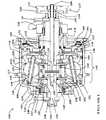
図1は、入力対出力速度比を変えることのできる球型のCVT100を示す。CVT100は、CVT100の中心を通りかつ自転車のフレームの2つの後部ドロップアウト10を越えて延設される中央のシャフト105を有する。各々が中央のシャフト105の対応する端に位置づけられる第1のキャップ・ナット106及び第2のキャップ・ナット107は、中央のシャフト105を上記両ドロップアウトに取り付ける。この実施形態は、自転車に使用するためのCVT100を示しているが、CVT100は変速機を利用する任意の機器に実装されてもよい。説明のために、中央のシャフト105は、CVTの他の構成要素の位置決めまたは動作を記述するための基準点として働くCVTの長手軸を画定している。本明細書で使用しているように、「軸方向」、「軸方向に」、「横方向」、「横方向に」という用語は、中央のシャフト105により画定される長手軸と同軸となる、または上記長手軸に平行となる位置または方向を指す。「半径方向」及び「半径方向に」という用語は、上記長手軸から垂直に延びる位置または方向を指す。 FIG. 1 shows a
図1及び2を参照すると、中央のシャフト105は、ケージ・アッセンブリ180、入力アッセンブリ155及び出力アッセンブリ160を半径方向及び横方向に支持する。この実施形態では、中央のシャフト105は、シフト・ロッド112を収容する穴199を含む。後述するように、シフト・ロッド112はCVT100内の速度比シフトを作動させる。 With reference to FIGS. 1 and 2, the
CVT100は、変速装置140を含む。変速装置140は、入力速度対出力速度比を変えるのに適した任意の機構であってもよい。ある実施形態では、変速装置140は、入力ディスク110と、出力ディスク134と、傾斜角可変のボールレッグ・アッセンブリ150と、アイドラ・アッセンブリ125とを含む。入力ディスク110は、中央のシャフト105を中心に回転可能式かつ同軸的に取り付けられるディスクであってもよい。入力ディスク110は、上記ディスクの半径方向の外端から一定の角度で接触面111の一点に至るまで延設される。実施形態によっては、接触面111は、例えば入力ディスク110へ付着するリングである、接触面111を支持する別の構造体であってもよい。接触面111は入力ディスク110へねじ込まれる、または圧入される場合もあれば、任意の適切な締結具または接着材で取り付けられる場合もある。
出力ディスク134は、圧入または他の方法で出力ハブ・シェル138へ取り付けるリングであってもよい。実施形態によっては、入力ディスク110及び出力ディスク134は、接触面111から半径方向の外側へ延設されるとともに、半径方向の剛性を高め、CVT100の軸方向力下でのこれらの部品の整合性に抵抗し、かつ半径方向の外側へ移動する軸方向力機構を許容するように構造的に支持する支持構造体113を有し、これによりCVT100の長さが短縮される。入力ディスク110及び出力ディスク134は、変速装置140内の潤滑剤がCVT100を介して循環することを許容するオイル・ポート136、135を有してもよい。 The
実施形態によっては、出力ハブ・シェル138は中央のシャフト105を中心にして回転可能な円筒形のチューブである。ハブ・シェル138は、CVT100の構成要素の大部分を収容する内側と、何であれ、CVTを使用する構成要素、機器または車両へ連接するのに適した外側とを有する。本明細書では、ハブ・シェル138の外側は自転車に実装されるように構成されている。しかしながら、CVT100は、回転性の入力及び出力速度を調節することが望ましい任意の機械に使用することができる。 In some embodiments, the
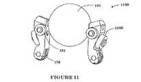
図1、2、10及び11を参照すると、CVTは、トルクを入力ディスク110から出力ディスク134へ伝達しかつ入力速度対出力速度比を変えるためのボールレッグ・アッセンブリ150を含んでもよい。実施形態によっては、ボールレッグ・アッセンブリ150は、球101と、球軸102と、脚103とを含む。軸102は、球101の中心を通って形成される穴を介して延設される概して円筒形であるシャフトであってもよい。実施形態によっては、軸102は、球101を軸102上に整列させるニードルまたはラジアル・ベアリングを介して、球101内の穴の表面と接合する。軸102は、脚103が球101の位置におけるシフトを作動できるように、穴の終端部である球101の両側を越えて延設される。軸102は、球101の端を越えて延設される部分で脚103の半径方向の外側の端と結合する。脚103は、球軸102を傾斜させる半径方向の延設部である。 1, 2, 10 and 11, the CVT may include a
軸102は、脚103の半径方向の外側の端に形成される穴を貫通する。実施形態によっては、脚103は、軸102のための穴が脚103を通る面取り部を有し、これは、脚103の側面と軸102との接点における低減された応力集中をもたらす。この低減された応力は、シフト力及びトルク反作用を吸収するボールレッグ・アッセンブリ150の能力を増大させる。脚103は、eリング等のクリップ・リングによって軸102上へ位置づけられる場合もあれば、軸102上へ圧入される場合もあるが、軸102及び脚103間は、他の任意のタイプの固定方法を利用することができる。また、ボールレッグ・アッセンブリ150は、球軸102の各端に取り付けられる転動体でありかつCVT100の他の部品によって整列されると軸102の回転接触をもたらすレッグ・ローラも含むことがある。実施形態によっては、脚103は、半径方向の内側の端に脚103の半径方向位置の制御を補助するカム車152を有し、これは、軸102の傾斜角を制御する。さらに他の実施形態では、脚103は、脚103がステータ800(図8)内に案内されかつ支持されることを可能にするステータ・ホイール1105(図11参照)へ結合する。図11に示すように、ステータ・ホイール1105は脚103の長手軸に対して角度づけされてもよい。実施形態によっては、ステータ・ホイール1105は、その中心軸が球101の中心と交差するように構成される。The
引き続き図1、2、10及び11を参照すると、様々な実施形態では、球101と軸102との接合部分は、他の実施形態に関して後述するベアリングの何れであってもよい。しかしながら、他の実施形態では、球101は軸に固定され、球101と共に回転する。このような実施形態によっては、ベアリング(図示されていない)は、軸102上に作用する横方向力が脚103及び/或いはケージ(様々な実施形態に関して後述する)から反作用を受けるように軸102と脚103の間に位置づけられる。このような実施形態によっては、軸102と脚103の間に位置づけられるベアリングは、ラジアル・ベアリング(球またはニードル)、ジャーナル・ベアリングまたは他の任意のタイプのベアリングもしくは適切な機構または手段である。 With continued reference to FIGS. 1, 2, 10 and 11, in various embodiments, the joint between the
次に、図1、2、3、4及び10を参照してアイドラ・アッセンブリ125について説明する。実施形態によっては、アイドラ・アッセンブリ125は、アイドラ126と、カム・ディスク127と、アイドラ・ベアリング129とを含む。アイドラ126は、概して円筒形のチューブである。アイドラ126は概して一定の外径を有するが、他の実施形態では、外径は一定ではない。外径は、中央部が端より小さい場合もあれば、中央で大きく、端で小さい場合もある。他の実施形態では、外径は一方の端でもう一方の端より大きく、両端間の変化は、シフト速度及びトルク要件に依存して線形であっても非線形であってもよい。 Next, the
カム・ディスク127はアイドラ126のどちらかの端または両端に位置づけられ、カム車152と相互に作用して脚103を作動する。図示した実施形態では、カム・ディスク127は凸状であるが、脚103の所望される動作を作る任意の形状であってもよい。実施形態によっては、カム・ディスク127は、その軸方向位置が脚103の半径方向位置を制御し、これにより軸102の傾斜角が管理されるように構成される。
実施形態によっては、両カム・ディスク127の半径方向の内径は軸方向に互いの方向へ向かって延び、一方のカム・ディスク127をもう一方のカム・ディスク127へ付着させる。本明細書では、カム延設部128は、中央のシャフト105を中心とする円筒を形成している。カム延設部128は一方のカム・ディスク127からもう一方のカム・ディスク127へ延び、そこでクリップ・リング、ナットまたは他の何らかの適切な締結具によって定位置に保持される。実施形態によっては、カム・ディスク127の一方または両方は、カム・ディスク延設部128上へねじ切りされて所定の位置に固定される。図示した実施形態では、カム・ディスク127の凸曲線は、アイドラ・アッセンブリ125の軸方向の中心から軸方向の遠位へ極大まで伸び、次に半径方向の外側へ、さらに軸方向の内側へアイドラ・アッセンブリ125の軸方向の中心まで戻る。カムのこの輪郭は、アイドラ・アッセンブリ125のシフトの間に軸方向の極値において発生する可能性のあるバインディングを低減させる。カムの形状は、他のものが使用されてもよい。 In some embodiments, the radial inner diameters of both
図1に示す実施形態では、シフト・ロッド112はCVT100の伝達比変化を作動させる。中央のシャフト105の穴199の内側に同軸的に位置づけられるシフト・ロッド112は、中央のシャフト105の片側を、キャップ・ナット107を越えて延設されるねじ切りされた端109を有する細長いロッドである。シフト・ロッド112の他端はアイドラ・アッセンブリ125内へと延設され、ここでシフト・ピン114を含む。シフト・ピン114は、シフト・ロッド112内に概して横方向へ取り付けられる。シフト・ピン114は、シフト・ロッド112がアイドラ・アッセンブリ125の軸方向位置を制御できるように、アイドラ・アッセンブリ125に係合する。親ねじアッセンブリ115は、シフト・ロッド112の中央のシャフト105内での軸方向位置を制御する。実施形態によっては、親ねじアッセンブリ125はシフト・アクチュエータ117を含み、シフト・アクチュエータ117は、その外径上に繋ぎ用のねじ山118セットを有しかつその内径の一部にシフト・ロッド112と係合するねじ山を有するプーリであってもよい。親ねじアッセンブリ115は、中央のシャフト105上のその軸方向位置に任意の手段によって保持されてもよいが、ここでは、プーリのスナップ・リング116によって所定の位置に保持されている。繋ぎ用のねじ山118は、シフト・テザー(図示されていない)に係合する。実施形態によっては、シフト・テザーは規格シフト・ケーブルであるが、他の実施形態では、シフト・テザーは、張力を支持しかつこれによりシフト・プーリ117を回転させることのできる任意のテザーであってもよい。 In the embodiment shown in FIG. 1,
図1及び2を参照すると、入力アッセンブリ155はトルクが変速装置140へ伝達されることを可能にする。入力アッセンブリ155は、チェーン(図示されていない)からの線形動作を回転動作に変換するスプロケット156を有する。ここでは、スプロケットが使用されているが、CVT100の他の実施形態は、例えばベルトからの動作を受け入れるプーリを使用してもよい。スプロケット156は、トルクを軸方向力生成機構へ伝達する。図示した実施形態では、上記軸方向力生成機構はトルクを入力ディスク110へ伝達するカム・ローダ154である。カム・ローダ154は、カム・ディスク157と、負荷ディスク158と、カム・ローラ159セットとを含む。カム・ローダ154は、トルクをスプロケット156から入力ディスク110へ伝達し、また、消散して入力ディスク110、球101、アイドラ126及び出力ディスク134のための接触力になる軸方向力も生成する。軸方向力は、概して、カム・ローダ154へ印加されるトルクの量に比例する。実施形態によっては、スプロケット156はトルクをカム・ディスク157へ、ハブ138はスピンするがスプロケット156はトルクを供給していないときの惰行機構として作用する一方向クラッチ(詳細は図示されていない)を介して印加する。実施形態によっては、負荷ディスク158は入力ディスク157と一体式の単体であってもよい。他の実施形態では、カム・ローダ154は出力ディスク134と一体式であってもよい。 With reference to FIGS. 1 and 2, the
図1及び2において、CVT100の内部構成要素は、エンド・キャップ160によってハブ・シェル138内に含まれている。エンド・キャップ160は、ハブ・シェル138の開放端へ付着する概して平坦なディスクであり、中心に入力ディスク157、中央のシャフト105及びシフト・ロッド112を通す穴を有する。エンド・キャップ160はハブ・シェル138に付着し、カム・ローダ154によって生成される軸方向力に応じる働きをする。エンド・キャップ160は、例えばアルミニウム、チタン、鋼または高強度の熱可塑性物質または熱硬化プラスチック等である、軸方向力に応じることのできる任意の材料で製造することができる。エンド・キャップ160は締結具(図示されていない)によってハブ・シェル138へ締め付けられるが、エンド・キャップ160はハブ・シェル138内に織り込まれる、または他の方法でハブ・シェル138へ取り付けられる場合もある。エンド・キャップ160は、その側面の半径付近に、プレローダ161を収容するカム・ローダ154に面して形成される溝を有する。プレローダ161は、超低トルク・レベルで初期型締力をもたらすばねであってもよい。プレローダ161は、ばねまたはOリングのような弾性材料等、カム・ローダ154へかつ延いては出力ディスク134へ初期力を供給することのできる任意の装置であってもよい。プレローダ161は、その寿命を通じて高いばね定数を有しかつ高レベルの弾性を維持することができる点で、ウェーブ・スプリングであってもよい。ここでは、プレローダ161はスラスト・ワッシャ162及びスラスト・ベアリング163によってエンド・キャップ160へ直接荷重される。この実施形態では、スラスト・ワッシャ162は、プレローダ161の溝を覆ってスラスト・ベアリング163のためのスラスト・レースを供給する典型的なリング・ワッシャである。スラスト・ベアリング163は、高レベルのスラスト容量を有し、構造的剛性を向上させるとともに、コンビネーション・スラスト・ラジアル・ベアリングに比べて許容差要件及びコストを低減させるニードル・スラスト・ベアリングであってもよいが、他の任意のタイプのスラスト・ベアリングまたはコンビネーション・ベアリングを使用することもできる。特定の実施形態では、スラスト・ベアリング163はボール・スラスト・ベアリングである。カム・ローダ154から発生する軸方向力は、スラスト・ベアリング163及びスラスト・ワッシャ162を介してエンド・キャップ160へと反作用される。エンド・キャップ160は、ハブ・シェル138へ付着してCVT100の構造を完成させる。 1 and 2, the internal components of
図1及び2において、カム・ディスク・ベアリング172はカム・ディスク157を中央のシャフト105に対して半径方向位置に保持し、一方でエンド・キャップ・ベアリング173はカム・ディスク157とエンド・キャップ160の内径との半径方向の配置構造を維持する。カム・ディスク・ベアリング172及びエンド・キャップ・ベアリング173は、ここではニードル・ローラ・ベアリングであるが、他のタイプのラジアル・ベアリングも使用可能である。ニードル・ローラ・ベアリングの使用は増大される軸方向フロートを許容し、ライダ及びスプロケット156が発生させる結合モーメントに対応する。CVT100の他の実施形態または本明細書に記述されている他の任意の実施形態では、カム・ディスク・ベアリング172及びエンド・キャップ・ベアリング173の各々または何れかをコンビネーション・ラジアル−スラスト・ベアリングの相補ペアに置き換えることもできる。このような実施形態では、ラジアル・スラスト・ベアリングは半径方向支持をもたらすだけでなく、スラスト・ベアリング163を補助しかつ少なくとも部分的に荷重を除くことができるスラストを吸収する能力もある。 1 and 2, the cam disk bearing 172 holds the
引き続き図1及び2を参照すると、中央のシャフト105を中心に同軸的に取り付けられる支持部材であって、中央のシャフト105とハブ・シェル138の閉鎖端の内径との間に保持される軸142は、ハブ・シェル138を中央のシャフト105に対して半径方向にアラインして保持する。軸142は、中央のシャフト105に角度的にアラインされた状態で固定される。ここでは、キー144が軸142をその角度配置状態で固定しているが、この固定は関連技術分野の熟練者に周知の任意手段で行うことができる。軸142とハブ・シェル138の内径との間にはラジアル・ハブ・ベアリング145が嵌合し、ハブ・シェル138を半径方向位置及び軸方向配置構造に維持する。ハブ・ベアリング145は、カプセル封入用軸キャップ143によって所定の位置に保持される。軸キャップ143は、中央のシャフト105の周囲に嵌合しかつここでは締結具147でハブ・シェル138に付着する中央の穴を有するディスクである。ハブ・シェル138とケージ189との間にはハブ・スラスト・ベアリング146が嵌合し、ケージ189及びハブ・シェル138の軸方向位置を維持する。 With continued reference to FIGS. 1 and 2, a support member that is coaxially mounted about the
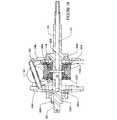
図3、4及び10は、上述のCVT100の代替実施形態であるCVT300を示す。上述のCVT100実施形態とこれらの図に示す実施形態とは、構成要素の多くが類似しているが、これらの図では、入力ディスク及び出力ディスク310、334の角度が各々、軸方向力に耐えるより大きい強度を見込みかつCVT300の半径方向の直径全体を短縮するために低減されている。この実施形態は、アイドラ・アッセンブリ325の軸方向移動を作動させる親ねじ機構がシフト・ロッド312上に形成される代替のシフト機構を示す。親ねじアッセンブリは、アイドラ・アッセンブリ325の内部または近くに存在するシフト・ロッド312の端に形成されるリード・スレッド313のセットである。1つまたは複数のアイドラ・アッセンブリ・ピン314は、カム・ディスク延設部328から半径方向にリード・スレッド313内へ延設され、シフト・ロッド312の回転に伴って軸方向に移動する。 3, 4 and 10 show a
図示した実施形態では、アイドラ326は外径が一定でなく、アイドラ326の両端で増す外径を有する。これにより、アイドラ326は、アイドラ326を中心位置から半径方向の遠位へと駆動する傾向のある動的接触力及び回転接触によって引き起こされるアイドラ326の力に抵抗することができる。しかしながら、これは単に一例であって、アイドラ326の外径は、アイドラ326に加わるスピン力に反作用しかつCVT300のシフトを補助するために設計者が希望する任意の方法で変更されてもよい。 In the illustrated embodiment, the idler 326 has an outer diameter that is not constant and increases at both ends of the
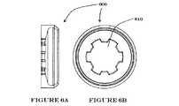
次に、図5a、5b、6a及び6bを参照すると、二部式のディスクがスプライン・ディスク600及びディスク駆動装置500で製造されている。ディスク駆動装置500及びスプライン・ディスク600は、ディスク駆動装置500上に形成されるスプライン510及びスプライン・ディスク600内に形成されるスプライン穴610を介して互いに嵌合する。スプライン510は、ディスク駆動装置500及びスプライン・ディスク600がCVT100、CVT300または他の任意の球状CVTに使用されるディスクを形成するように、スプライン穴610内に嵌合する。スプライン・ディスク600は、変速装置140、340が変速装置140、340の構成要素の製造公差に対する感受性を低減するような半径方向の平衡位置を発見することを可能にする、システム内のコンプライアンスを提供する。 5a, 5b, 6a and 6b, a two-part disk is manufactured with a
図7は、CVT100、CVT300、他の球状CVTまたは他の任意タイプのCVTにおいて使用可能なカム・ディスク700を示す。カム・ディスク700は、その半径方向の外端に形成されるカム・チャネル710を有する。カム・チャネル710は、この実施形態では(ベアリングのボール等の)球であるカム・ローラのセット(図示されていない)を収容する。但し、これらのカム・ローラは、変速装置140、340に印加される軸方向力をCVTに印加されるトルクに比例する量で加減するためにカム・チャネル710の形状との組合せでトルクをトルク/軸方向力成分に変換する他の任意の形状であってもよい。他に、このような形状には、円筒形のローラ、バレル・ローラ、非対称のローラまたは他の任意の形状が含まれる。多くの実施形態において、カム・ディスク・チャネル710に使用される材料は、好適には、カム・ディスク700が経験することになる荷重における過剰または永久的な変形に対抗するに足る強度である。高トルクのアプリケーションでは、特殊な硬化が必要な場合もある。実施形態によっては、カム・ディスク・チャネル710は、40HRCを超えるロックウェル硬さ値まで硬化された炭素鋼で製造される。カム・ローダ(図1の154または他の任意タイプのカム・ローダ)の動作効率は、上記硬さ値によって、典型的には、効率を上げるための硬さ増加によって影響され得るが、高度の硬化は、カムの荷重成分を脆くする場合があり、コストも高まる場合がある。実施形態によっては、硬さは50HRCを超えるものであり、他の実施形態では、55HRC、60HRC及び65HRCを超える。 FIG. 7 shows a
図7は、コンフォーマル・カムの一実施形態を示す。即ち、カム・チャネル710の形状は、カム・ローラの形状に適する。チャネル710はローラの形状に適することから、チャネル710はベアリング・ローラのリテーナとして機能し、ケージ・要素の要件が除去される。図7に示す実施形態は一方向カム・ディスク700であるが、カム・ディスクは、CVT1300(図13参照)におけるもののような双方向カムであってもよい。ベアリング・ローラ・リテーナの必要がなくなることにより、CVTの設計は単純になる。また、コンフォーマルなカム・チャネル710もベアリング・ローラとチャネル710との接触応力が低減されることを可能にし、ベアリング・ローラのサイズ及び/または計数の低減または材料選択の柔軟さの拡大が見込まれる。 FIG. 7 illustrates one embodiment of a conformal cam. That is, the shape of the
図8は、球状CVT100、300(及び他のタイプ)における変速装置140、340のケージ189の堅固な支持構造体の製造に使用されるケージ・ディスク800を示す。ケージ・ディスク800は、シフト中に脚103をそれらの半径方向の内側及び外側への移動に伴って案内するように成形される。またケージ・ディスク800は、軸102の角度配置構造も行う。実施形態によっては、個々の軸102のための2つのケージ・ディスク800の対応する溝は、変速装置140、340におけるシフト力を低減するために角度方向へ僅かに補正される。 FIG. 8 shows a
脚103は、ステータ内のスロットによって案内される。脚103上のレッグ・ローラ151は、ステータ内の円形の輪郭に沿って進む。レッグ・ローラ151は、概して、シフト力または牽引接触スピン力によって課される並進力を打ち消す並進反作用点になる。脚103及びその個々のレッグ・ローラ151は、CVT比が変更されると平面動作で移動し、よって球101付近を中心とする円形の包絡線を描く。レッグ・ローラ151は脚103の中心より補正されることから、レッグ・ローラ151は同様に補正される包絡線を描く。各ステータ上へレッグ・ローラ151の平面動作に一致する共通の輪郭を生成するためには、各脚103においてローラが補正される同じ量だけ溝の中心から補正される円形の切断が必要とされる。この円形の切断は回転のこカッタで実行されてもよいが、その場合は各溝に個々の切断が必要になる。これらの切断は独立していることから、ステータ毎の変動に加えて、単一のステータにおいて溝毎に公差が変わる見込みがある。この余分な機械加工工程をなくす方法は、旋盤回し操作によって生成され得る単一の輪郭を供給することである。トロイダル形の旋盤切断は、この単一の輪郭を一度の回転操作で製造することができる。トロイダル・切断の中心は、レッグ・ローラ103の補正を補償するために、球101の中心位置から半径方向に離して調節される。 The
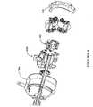
次に、図1、9及び12を参照すると、スペーサ1210が2つのケージ・ディスク1220を支持しかつこれらを離隔する、幾つかのCVTと共用するための潤滑強化用潤滑スペーサ900を実装するケージ・アッセンブリ1200の代替実施形態が示されている。図示した本実施形態において、この場合はケージ389である動力伝達要素のための支持構造体は、入力及び出力側のケージ・ディスク1220をケージ締結具1230で1つまたは複数の潤滑スペーサ900を含む複数のスペーサ1210へ取り付けることによって形成される。この実施形態では、ケージ締結具1230はねじであるが、これらは任意のタイプの締結具または締結方法であってもよい。潤滑スペーサ900は、ハブ・シェル138の表面から潤滑剤をこすり落とすためと、その潤滑剤を変速装置140、340の中心要素へ戻す方向へ向けるためのスクレーパ910を有する。幾つかの実施形態の潤滑スペーサ900は、潤滑剤の流れを、潤滑剤を最もよく利用する領域へ方向づける手助けをする通路920も有する。実施形態によっては、潤滑スペーサ900における通路920間の部分は、潤滑剤の流れを通路920の方向へ向ける隆起したウェッジ925を形成する。スクレーパ910はスペーサ900と一体式である場合もあれば、分離していて、潤滑剤のハブ・シェル138からのこすり落としを向上させるゴムを含む、但し、これに限定されないスクレーパ910の材料とは異なる材料で製造される場合もある。スペーサ1210及び潤滑スペーサ900の両端は、ケージ・ディスク1220と結合する表面を形成するために垂直に延設されるフランジ状のベース1240で終わる。図示した実施形態のベース1240は、レッグ・ローラ151が載る上述の曲面を形成するように、概して、ベース1240に面する側面が平らで、球101に面する側面が丸くなっている。また、ベース1240は、脚103がその行程で乗るチャネルも形成する。 Referring now to FIGS. 1, 9 and 12, a cage implementing a lubrication-enhanced
次に、図3、9及び10を参照して、潤滑のシステム及び方法の実施形態について説明する。潤滑剤は、球101の回転に伴って球101の赤道へ向かって流れる傾向があり、次に潤滑剤はハブ・シェル138に向かって噴霧される。潤滑剤の中にはハブ・シェル138の最大径を有する内壁に落下しないものもあるが、こうした潤滑剤も遠心力によってハブ・シェル138の最大の内径方向へと流れる。スクレーパ910は、ハブ・シェル138の内側に堆積する潤滑剤を除去するように垂直に位置づけられる。潤滑剤は、重力によってV字形のウェッジ925の各側面から通路920へと引き下ろされる。スペーサ900は、通路920の半径方向の内端がカム・ディスク127及びアイドラ126に近接して終わるように置かれる。このようにして、アイドラ126及びカム・ディスク127は、ハブ・シェル138内を循環する潤滑剤を受け入れる。ある実施形態では、スクレーパ910のサイズは、ハブ・シェル138を約1000分の30インチだけ除去するように決定される。当然ながら、この除去は、異なるアプリケーションに依存してこれより大きく、または小さくなることがある。 An embodiment of a lubrication system and method will now be described with reference to FIGS. The lubricant tends to flow toward the equator of the
図3及び10に示すように、カム・ディスク127は、アイドラ226に面するその側面が、通路920から落下する潤滑剤を受け入れて、これをカム・ディスク127とアイドラ226との間の空間へ配向すべく角度づけされるように構成されてもよい。潤滑剤は、アイドラ226上へ流れた後、アイドラ226の最大径の方向へ流れ、潤滑剤の幾分かはここで軸102へ噴霧される。潤滑剤の幾分かは、通路920からアイドラ226上へ落下する。この潤滑剤は、アイドラ226及び球101とアイドラ226との間の接触面を潤滑する。アイドラ226の各側面は傾斜していることから、潤滑剤の幾分かはアイドラ226の両端へと遠心的に流れ、そこで放射状に霧散する。 As shown in FIGS. 3 and 10, the
図1、3及び10を参照すると、実施形態によっては、アイドラ126、226から軸102の方向へ噴霧される潤滑剤は溝345へ落下し、溝345は潤滑剤を受け入れて、これを球101の内部へポンピングする。潤滑剤の幾分かは、入力ディスク110及び出力ディスク134が球101に接触する接触面111へも落下する。潤滑剤は、球101の片側を出るにつれて、遠心力下で球101の赤道方向へ流れる。この潤滑剤の幾分かは入力ディスク110と球101との接触面111に接触し、次いで球101の赤道方向へ流れる。潤滑剤の幾分かは、出力ディスク134の球101とは反対側に面する側面に沿って半径方向へ流れ出る。実施形態によっては、入力ディスク110及び/または出力ディスク134に各々潤滑ポート136及び135が装備される。潤滑ポート135、136は、潤滑をハブ・シェル138の最大内径へと方向づける。 With reference to FIGS. 1, 3 and 10, in some embodiments, the lubricant sprayed from
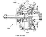
図13は、CVT1300内で軸方向力の生成及び分散を共有する2つのカム・ローダ1354を有するCVT1300の実施形態を示す。ここでは、カム・ローダ1354は、入力ディスク1310及び出力ディスク1334に隣接して位置づけられている。CVT1300は、トルクが、出力ディスク1334を介して入力されかつ入力ディスク1310を介して出力されるために如何にして入力ディスク1310を介して供給されかつ出力ディスク1334を介して出力されるか、またはその逆を示している。 FIG. 13 shows an embodiment of a
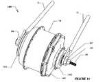
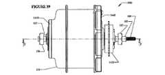
図14は、本明細書で説明しているCVTの実施形態の発明的特徴を組み込むように構成された自転車ハブ1400を描いている。ハブ1400の幾つかの構成要素は上述の構成要素と同じであり、よって、こうした構成要素の詳述は控える。ハブ1400は、ハブ・キャップ1460へ結合するハブ・シェル138を含む。実施形態によっては、ハブ1400は、ハブ・キャップ1460の反対側でハブ・シェル138の端を密封するエンド・キャップ1410も含む。ハブ・シェル138、ハブ・キャップ1460及びエンド・キャップ1410は、好適には、構造的強度及び剛性をもたらす材料で製造される。このような材料には、例えば鋼、アルミニウム、マグネシウム、高強度プラスチック、他が含まれる。実施形態によっては、所定の技術的アプリケーションの特殊な要件に依存して、他の材料が適切であることもある。例えば、ハブ・シェル138は、複合材料、熱可塑性樹脂、熱硬化プラスチック、他から製造されてもよい。 FIG. 14 depicts a
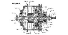
次に、図14を参照すると、図示されているハブ1400は、その内部に本明細書で提示しているCVTの実施形態を収容する。メイン・シャフト105は、ハブ1400を支持し、かつ自転車または他の車両または機器のドロップアウト10への取り付けを準備する。この実施形態のメイン・シャフト105については、図41から43を参照して詳述する。実施形態によっては、図15から18に示すように、CVT1500は、ねじ切りされた端109を有するロッド112を組み込んだシフト機構を含む。ナット106及び107は、ドロップアウト10をメイン・シャフト105へ固定する。図14の実施形態では、ハブ1400は、トルク入力をCVT1500内に伝達するための入力シャフト(図33及び図40参照)へ機能的に結合されるフリーホイール1420を含む。本明細書では、CVTの様々な実施形態及び特徴を自転車のアプリケーションに関連して論じているが、CVT及びその特徴は、容易に認識され得る修正によって変速装置を使用する任意の車両、機械または装置に使用可能である点は留意されるべきである。 Referring now to FIG. 14, the
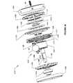
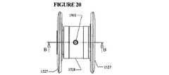
図15及び16を参照すると、ある実施形態において、CVT1500は、トルクを球状の牽引ローラ(ここでは球101として示されている)へ伝達するための入力ディスク1545を有する。図16は、CVT1500の部分分解図である。球101は、トルクを出力ディスク1560へ伝達する。この実施形態では、CVT1500の様々な特徴を明確に示す目的で1つの球101を示しているが、CVTの様々な実施形態は、特定の各アプリケーションのトルク、重量及びサイズ要件に依存して2個から16個またはそれ以上に及ぶ何れかの球101を使用する。異なる実施形態は、2、3、4、5、6、7、8、9、10、11、12、13、14、15、16個またはそれ以上の球101の何れかを使用する。メイン・シャフト105を中心に同軸的に取り付けられるアイドラ1526は球101に接触してその支えとなり、メイン・シャフト105を中心とするその半径方向位置を維持する。幾つかの実施形態の入力ディスク1545は、潤滑剤のCVT1500内の循環を促進する潤滑ポート1590を有する。 Referring to FIGS. 15 and 16, in one embodiment,
追加的に、図37から38を参照すると、球101は軸3702上で回転する。脚103及びシフト・カム1527は、共働して軸3702の位置内のシフトを作動するレバーとして機能する。上記シフトは、球101を傾斜させ、これにより、既に述べたような伝達比によるシフトが達成される。ケージ1589(図22から24参照)は、シフト・カム1527による脚103の半径方向動作の作動に伴って脚103のサポート及び配置構造を準備する。ある実施形態では、ケージは、ステータ・スペーサ1555によって結合されるステータ1586及び1587を含む。他の実施形態では、他のケージ180、389、1200が使用される。 Additionally, referring to FIGS. 37-38, the
追加的に図41から43を参照すると、図示されている実施形態では、ケージ1589はメイン・シャフト105と同軸的に、かつメイン・シャフト105を中心として回転不能式に取り付けられる。この実施形態では、ステータ1586はメイン・シャフト105のフランジ4206へ固定的に取り付けられる。追加のフランジ1610は、ステータ1587を所定の位置に保持する。キー1606は、フランジ1610を、キー1606を受け入れるためのキー・シート1608を有するメイン・シャフト105へ結合する。当然ながら、関連技術における一般的な技術者は、メイン・シャフト105をフランジ1610へ結合する、またはステータ1586、1587をフランジ1620、4206へ結合する多くの同等かつ代替方法が存在することを容易に認識するであろう。特定の実施形態では、メイン・シャフト105は、フランジ1610を軸方向に位置づけて拘束する働きをするショルダ4310を含む。 With additional reference to FIGS. 41-43, in the illustrated embodiment, the
エンド・キャップ1410はラジアル・ベアリング1575上に取り付けられ、ラジアル・ベアリング1575自体はフランジ1610を覆って取り付けられる。ある実施形態では、ラジアル・ベアリング1575は、地上の反作用による荷重を支持しかつハブ・シェル138をメイン・シャフト105に半径方向へアラインするアンギュラ・コンタクト・ベアリングである。実施形態によっては、ハブ1400は、メイン・シャフト105の一方の端または両端にシールを含む。例えばここでは、ハブ1400は、ハブ・シェル138とエンド・キャップ1410とが結合される端にシール1580を有する。さらに、出力側に軸方向力の予圧をもたらすためと、ハブ・シェル138の軸方向位置を維持するために、ハブ1400は、ステータ1587とラジアル・ベアリング1575との間にスペーサ1570及びニードル・スラスト・ベアリング(図示されていない)を含んでもよい。スペーサ1570は、フランジ1610を中心として同軸的に取り付けられる。実施形態によっては、ニードル・スラスト・ベアリングは使用されなくてもよいが、このような場合、ラジアル・ベアリング1575はスラスト荷重に対処するように適したアンギュラ・コンタクト・ベアリングであってもよい。関連技術分野の一般的な技術者は、スペーサ1570、ニードル・スラスト・ベアリング及びラジアル・ベアリングがもたらす半径方向荷重及びスラスト荷重を支える機能を提供する代替手段を容易に認識するであろう。 The
引き続き図14、15及び16を参照すると、図示されている実施形態では、ハブ1400の変速装置1500は、一方の端でトーション・ディスク1525と機能的に結合する入力シャフト1505を含む。入力シャフト1505の他端は、フリーホイール・キャリア1510を介してフリーホイール1420と機能的に結合する。トーション・ディスク1525は、ランプ3610(図36参照)を有するカム・ディスク1530へトルクを伝達するように構成される。負荷カム・ディスク1530は、トルク及び軸方向力を、第2の負荷カム・ディスク1540上へ作用するローラ2504のセット(図25参照)へ伝達する。入力ディスク1545は、トルク及び軸方向力の入力を受け入れる第2の負荷カム・ディスク1540へ結合する。実施形態によっては、ローラ2504はローラ・ケージ1535によって所定の位置に保持される。 With continued reference to FIGS. 14, 15 and 16, in the illustrated embodiment, the
周知のように、トラクション型CVTの多くは、所定レベルのトルクの伝達に際して、球101と入力ディスク1545との間の滑りを防止するクランプ機構を利用している。クランプ機構の準備は、本明細書では軸方向力の生成、または軸方向力生成器の供給として言及されることがある。先に述べた、負荷カム1540に呼応してローラ2504を介して作用する負荷カム・ディスク1530の構成は、このような軸方向力生成機構の1つである。しかしながら、軸方向力の生成装置またはサブアッセンブリはCVT内に軸方向力を生成することから、実施形態によっては、CVT自体の内部にこれに対抗する反作用力も生成される。追加的に図25及び26を参照すると、CVT1500を例示するその実施形態では、反作用力は、各々第1及び第2のレース1602及び1603を有するスラスト・ベアリングによって少なくとも部分的に対抗される。図示されている実施形態では、ベアリング・エレメントは示されていないが、球、ローラ、バレル・ローラ、非対称ローラまたは他の任意タイプのローラであってもよい。さらに、実施形態によっては、レース1602の一方または両方は、鋼、ベアリング鋼、セラミックまたはベアリング・レースに使用される他の任意の材料等の様々なベアリング・レース材料で製造される。第1のレース1602はトーション・ディスク1525と突き合わされ、第2のレース1603はハブ・キャップ1460と突き合わされる。図示されている実施形態のハブ・キャップ1460は、軸方向力機構が生成する反作用力を吸収する手助けをする。実施形態によっては、軸方向力の生成は、ウェーブ・スプリング1515またはトーション・スプリング2502(図25に関する後の説明参照)等の1つまたは複数の軸方向ばねのような追加装備的プレローダを含む。 As is well known, many of the traction type CVTs use a clamp mechanism that prevents slipping between the
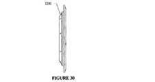
図15から18、図22から24及び43を参照すると、CVT1500の所定のサブアッセンブリが示されている。ステータ1586は、メイン・シャフト105のショルダ4208上に取り付けられ、メイン・シャフト105のフランジ4206と突き合わされる。ステータ1587は、フランジ1610のショルダ1810上に取り付けられる。ここでは、フランジ4206はねじ(図示されていない)でステータ1586へ取り付けられるが、他の実施形態では、ステータ1587はショルダ1810上へねじ込まれる。但し、ステータ1587は任意の方法または手段でショルダ1810へ取り付けられてもよい。フランジ1610及び4206はメイン・シャフト105へ回転不能式に固定されることから、ステータ1586及び1587で作られるケージ1589は、とりわけ、この実施形態ではメイン・シャフト105へ回転不能式に付着する。ステータ・スペーサ1555は、ケージ1589へ構造上の追加的な強度及び剛性をもたらす。さらに、ステータ・スペーサ1555は、ステータ1586及び1587間に精確な軸方向スペーシングを実装する手助けをする。ステータ1586及び1587は、案内溝2202を介して脚103及び軸3702を案内しかつ支持する。 Referring to FIGS. 15-18, 22-24 and 43, a predetermined subassembly of
次に、図15から21、37及び38を参照すると、球101は軸3702を中心として回転し、アイドラ1526と接触した状態にある。ベアリング1829は、メイン・シャフト105を中心に同軸的に取り付けられてアイドラ1526をその半径方向位置に支持するが、このベアリング1829は、アイドラ1526から分離されていても、一体式であってもよい。シフト・ロッド112に制御されるシフト・ピン114は、シフト・カム1527の軸方向移動を作動する。シフト・カム1527は脚103を作動し、機能的に、球101の軸3702上にレバーの使用または旋回作用がもたらされる。実施形態によっては、CVT1500は、シフト・ピン114がアイドラ1526を妨害しないように保つリテーナ1804を含む。リテーナ1804は、プラスチック、金属または他の適切な材料で製造されるリングであってもよい。リテーナ1804は両ベアリング1829間に嵌合され、シフト・カム延設部1528を中心として同軸的に取り付けられる。 Next, referring to FIGS. 15 to 21, 37, and 38, the
図19から21は、図示されているCVT1500のシフト・カム1527の一実施形態を示す。各シフト・カム・ディスク1572は、脚103が沿って乗る輪郭2110を有する。ここでは、輪郭2110は概して凸形を有する。通常、輪郭2110の形状は脚103の所望される動作によって決定され、最終的にはこれがCVT1500のシフト・パフォーマンスに影響する。シフト・カムの輪郭については、後に詳述する。図が示すように、シフト・カム・ディスク1527の一方は、メイン・シャフト105を中心として取り付けられる延設部1528を有する。図示されている実施形態の延設部1528は、アイドラ1526を越えて延設されかつもう一方のシフト・カム・ディスク1527と結合するに足る長さである。ここでは、結合は滑り嵌め及びクリップによってもたらされる。しかしながら、他の実施形態では、両シフト・カム1527は、ねじ山、ねじ、締り嵌めまたは他の任意の連接方法によって互いに締め付けられてもよい。実施形態によっては、延設部1528は各シフト・カム1527からの延設部として供給される。シフト・ピン114は、延設部1528を介して進む穴1910に嵌る。実施形態によっては、シフト・カム1527は、アイドラ・ベアリング1829を介する潤滑の流れをさらに良くするオリフィス1920を有する。実施形態によっては、アイドラ・ベアリング1829は延設部1528上へ圧入される。このような実施形態では、オリフィス1920は、シフト・カム1527にツールを通し、延設部1528からアイドラ・ベアリング1829を押し離させることにより、延設部1528からアイドラ・ベアリング1829を除去する手助けをする。特定の実施形態では、アイドラ・ベアリング1829はアンギュラ・コンタクト・ベアリングであるが、他の実施形態では、これらはラジアル・ベアリングまたはスラスト・ベアリングもしくは他の任意タイプのベアリングである。シフト・カム1527の製造には、多くの材料が適する。例えば、実施形態の中には、鋼、アルミニウム及びマグネシウム等の金属を使用するものがあり、他の実施形態は、複合材料、プラスチック及びセラミック等の他の材料を使用するが、これらは各々特定のアプリケーションの条件に依存する。 FIGS. 19-21 illustrate one embodiment of the
図示されているシフト・カム1527は、概して凸形を有するシフト・カムの輪郭2110の一実施形態である。シフト・カムの輪郭は、通常、アイドラ1526とボールレッグ・アッセンブリ1670(図16参照)との間の接点の位置及び球101とアイドラ1526との軸方向の相対移動量に従って変わる。 The illustrated
次に、図16及び図18から21に示されている実施形態を参照すると、シフト・カム1527の輪郭は、球101に対するアイドラ1526の軸方向の並進が球101の軸角度の変化に比例する類のものである。ここでは、球101の軸角度を「γ」と呼ぶ。出願人は、γの変化に対するアイドラ1526の軸方向の並進制御がCVT比の制御力に影響することを発見している。例えば、図示されているCVT1500では、アイドラ1526の軸方向並進がγの変化に線形比例していれば、シフト・カム1527及び球−脚接合部分における垂直力は概して軸3702に平行である。これは、水平シフト力のボールレッグ・アッセンブリ1670を中心とするシフト・モーメントへの効率的な変換を有効化する。 Referring now to the embodiment shown in FIGS. 16 and 18 to 21, the contour of the
アイドラの並進とγとの線形的相関性は、アイドラの並進が数学的に球101の半径と、γ角度と、RSFとの積(即ち、アイドラの並進=球半径×γ角度×RSF)であることから与えられる。ここで、RSFはローラの滑り係数である。RSFは、球101とアイドラ126との間の横方向のクリープ速度を記述する。ここで使用されている「クリープ」とは、物体の別の物体に対する不連続の局部動作である。牽引駆動装置では、駆動要素から被駆動要素への牽引接合部分を介する動力の伝達はクリープを要する。通常、動力伝達方向のクリープは、「回転方向のクリープ」と呼ばれる。時として、駆動及び被駆動要素は動力伝達方向に直交する方向のクリープを経験するが、このような場合、このクリープ成分は「横方向クリープ」と呼ばれる。CVTの動作中、球101及びアイドラ1526は互いの上で転がる。アイドラが軸方向へ(即ち、回転方向に直交して)シフトされると、アイドラ1526と球101との間に横方向クリープが課される。1.0に等しいRSFは、純粋な回転を指す。1.0未満のRSFでは、アイドラ1526は球101の回転より遅く並進する。1.0より高いRSF値では、アイドラ1526は球101の回転より速く並進する。 The linear correlation between the idler translation and γ is that the idler translation is mathematically the product of the radius of the
引き続き、図16及び図18から21に示されている実施形態を参照すると、出願人は、横方向クリープ及び/またはアイドラ1526とボールレッグ・アッセンブリ1570との間の接合部分の位置決めの任意の変動に対してカム輪郭を配置する方法を考案している。この方法は、異なるカム輪郭を生成し、シフト力及びシフタ変位に対する効果を決定する手助けをする。ある実施形態では、本方法は、所望されるカム輪郭を有する二次元基準曲線を定義するパラメータ方程式の使用を含む。上記曲線は、次に、シフト・カム127のモデルを生成するために使用される。本方法の一実施形態では、基準曲線のパラメータ方程式は次の通りである。 Continuing with reference to the embodiment shown in FIGS. 16 and 18-21, Applicants will note any variation in lateral creep and / or positioning of the interface between
θ=2×GAMMA_MAX×t−GAMMA_MAX
x=LEG×sin(θ)−0.5×BALL_DIA×RSF×θ×π/180+0.5×ARM×cos(θ)
y=LEG×cos(θ)−0.5×ARM×sin(θ)
z=0
角度θは、最小γ(実施形態によっては、−20度)から最大γ(実施形態によっては、+20度)まで変わる。GAMMA_MAXは、γの最大値である。パラメータ・レンジの変数「t」は、0から1までの範囲で変わる。ここで、「x」及び「y」はカム車152(図1参照)の中心点である。x及びyの方程式は、パラメータである。「LEG」及び「ARM」は、ボールレッグ・アッセンブリ1670とアイドラ1526及びシフト・カム1527との接合部分の位置を定義する。より具体的には、LEGは、ボールレッグ・アッセンブリ1670の球心棒3702の軸からボールレッグ・アッセンブリ1570の対応する2つのカム車152の中心を通る、球心棒3702に平行な線までの垂直距離である。θ = 2 × GAMMA_MAX × t-GAMMA_MAX
x = LEG × sin (θ) −0.5 × BALL_DIA × RSF × θ × π / 180 + 0.5 × ARM × cos (θ)
y = LEG × cos (θ) −0.5 × ARM × sin (θ)
z = 0
The angle θ varies from a minimum γ (−20 degrees in some embodiments) to a maximum γ (+20 degrees in some embodiments). GAMMA_MAX is the maximum value of γ. The parameter range variable “t” varies in the range from 0 to 1. Here, “x” and “y” are the center points of thecam wheel 152 (see FIG. 1). The x and y equations are parameters. “LEG” and “ARM” define the location of the junction of
RSF値は、ゼロより大きいことが好適である。CVT100は、RSF約1.4のアプリケーションを明示している。出願人は、RSFゼロはCVTのシフトに必要な力を劇的に増大させることを発見している。通常、RSFは1.0より大きく、2.5より小さい値が好適である。 The RSF value is preferably greater than zero.
引き続き図16及び図18から21に示されている実施形態を参照すると、図示されているこのCVT100の実施形態には、最大γ角度に対する最大RSFが存在している。例えば、γが+20度である場合、RSFは約1.6で最大になる。RSFはさらに、球101のサイズ及びアイドラ1526のサイズ及びカム車152の位置決めに依存する。With continued reference to the embodiment shown in FIGS. 16 and 18 to 21, there is a maximum RSF for the maximum γ angle in the illustrated embodiment of
CVTをシフトするために入力されるエネルギーについて言えば、このエネルギーは、大きい変位及び小さい力として(高いRSF値をもたらす)、または小さい変位及び大きい力として(低いRSF値をもたらす)入力されてもよい。所定のCVTに関しては、許容可能な最大シフト力が存在し、かつ許容可能な最大変位も存在する。故に、トレードオフを行えば、任意の特定アプリケーションに関して設計者には実行されるべき様々な設計オプションがもたらされる。ゼロより大きいRSFは、所望されるシフト比の達成に必要な軸方向変位を増大することによって、必要なシフト力を減らす。最大変位は、実施形態によっては、グリップまたはトリガ・シフト等の特定のシフト機構の限度によって決定されるが、実施形態によっては、これもCVT100のパッケージ制限に影響される、或いは交互的に影響されることがある。 With respect to the energy input to shift the CVT, this energy may be input as a large displacement and small force (resulting in a high RSF value) or as a small displacement and large force (resulting in a low RSF value). Good. For a given CVT, there is a maximum allowable shift force and there is also a maximum allowable displacement. Thus, the trade-off provides the designer with various design options to be performed for any particular application. An RSF greater than zero reduces the required shift force by increasing the axial displacement required to achieve the desired shift ratio. The maximum displacement is determined by the limits of a specific shift mechanism, such as a grip or trigger shift, in some embodiments, but depending on the embodiment, this is also affected or alternately affected by
時間当たりのエネルギーは、別の因子である。所定のアプリケーションのシフト・レートは、シフト機構の作動に使用される動力源に依存して、シフト・レートを達成するための所定レベルの力または変位を必要とする場合がある。例えば、CVTのシフトに電気モータを使用する所定のアプリケーションでは、幾つかの例において低トルクで高い速度を有するモータが好まれる。動力源は速度に偏向されるため、RSFは変位へと偏向されることになる。油圧シフトを使用する他のアプリケーションでは、低フローにおける高圧の方が高フローにおける低圧より適する可能性がある。故に、アプリケーションに依存して、RSFは動力源に合うように低い方が選ばれることになる。 Energy per hour is another factor. The shift rate for a given application may require a predetermined level of force or displacement to achieve the shift rate, depending on the power source used to operate the shift mechanism. For example, in certain applications that use an electric motor for CVT shifting, motors with low torque and high speed are preferred in some examples. Since the power source is deflected to speed, the RSF will be deflected to displacement. In other applications using hydraulic shifts, high pressure at low flow may be more suitable than low pressure at high flow. Therefore, depending on the application, the lower RSF will be chosen to suit the power source.
γに線形的に相関されるアイドラの並進は、所望される唯一の関係性ではない。従って、例えば、アイドラの並進がCVT比に線形的に比例することが望ましければ、RSF係数は、アイドラの位置とCVT比との関係が線形的に比例するようにγ角またはCVT比の関数にされる。幾つかのタイプの制御スキームにとって、これは望ましい特徴である。 The idler translation linearly correlated to γ is not the only relationship desired. Thus, for example, if it is desired that the translation of the idler be linearly proportional to the CVT ratio, the RSF coefficient is a function of the γ angle or the CVT ratio so that the relationship between the idler position and the CVT ratio is linearly proportional. To be. This is a desirable feature for some types of control schemes.
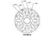
図22から24は、CVT1500内で使用可能なケージ1589の一例を示す。図示されているケージ1589は、ステータ・スペーサ1555のセット(明確さのために1つのみ示されている)によって互いに結合される2つのステータ1586及び1587を有する。この実施形態におけるステータ・スペーサ1555は、ステータ1586及び1587の外周に固定している。ここでは、スペーサ1555は、ねじでステータ1586及び1587へ取り付けられる。しかしながら、ステータ1586及び1587とスペーサ1555とは、圧入、ねじ込みまたは他の任意の方法または手段等の他の取り付け手段用に構成されてもよい。実施形態によっては、スペーサ1555の一端はステータ1586または1587の一方に永久的に取り付けられる。実施形態によっては、スペーサ1555は、構造的剛性をもたらす材料で製造される。ステータ1586及び1587は、脚103及び/または軸3702を案内しかつ支持する溝2202を有する。特定の実施形態では、脚103及び/または軸3702は、溝2202上に乗るホイール(図11のアイテム151または他の実施形態の等価物)を有する。 FIGS. 22-24 show an example of a
図24は、ステータ1586の溝2202とは反対側の側面を示す。この実施形態では、穴2204はステータ・スペーサ1555をステータ1586へ取り付けるねじを受け入れる。内側の穴2210は、ステータ1586をメイン・シャフト105のフランジ4206へ取り付けるねじを受け入れる。ステータ1586の幾つかの実施形態を軽量化するために、この実施形態ではステータ1586から材料が、カットアウト2206として示されているように除去されている。重量及びボールレッグ・アッセンブリ1670の要素間の間隙を考慮して、ステータ1586は、この実施形態の場合のように追加のカットアウト2208を含んでもよい。 FIG. 24 shows a side surface of the
次に、図25、26及び36の実施形態を参照して、図15のCVT1500と共用され得る軸方向力生成機構の一実施形態について説明する。図25及び26は、部分分解図である。入力シャフト1505は、トルク入力をトーション・ディスク1525へ与える。トーション・ディスク1525は、ランプ3610を有する負荷カム・ディスク1530と結合する。負荷カム・ディスク1530の回転に伴って、ランプ3610はローラ2504を作動し、ローラ2504は第2の負荷カム・ディスク1540のランプ3610上に乗る。次に、ローラ2504は負荷カム・ディスク1530及び1540の間で押されて所定位置に填り込み、負荷カム・ディスク1530からのトルク及び軸方向力の双方を負荷カム・ディスク1540へ伝達する。実施形態によっては、CVT1500は、ローラ2504の正しい配置構造を保証するローラ・リテーナ1535を含む。ローラ2504は、球形、円筒形、バレル形、非対称または特定のアプリケーションに適する他の形状であってもよい。実施形態によっては、ローラ2504は各々、アプリケーションによっては所望に従ってローラ2504をランプ3610より上または下に偏向する、ローラ・リテーナ1535または他の構造体へ取り付けられる個々のばね(図示されていない)を有する。図示されている実施形態では、入力ディスク1545は負荷カム・ディスク1540と結合するように構成され、入力トルク及び軸方向力の両方を受け入れる。軸方向力は次に、球101を入力ディスク1545、出力ディスク1560及びアイドラ1526間にクランプする。 Next, an embodiment of an axial force generation mechanism that can be shared with the
図示されている実施形態では、負荷カム・ディスク1530は、ドエルピンでトーション・ディスク1525へ固定される。但し、負荷カム・ディスク1530をトーション・ディスク1525へ固定する他の方法が使用されてもよい。さらに、実施形態によっては、負荷カム・ディスク1530はトーション・ディスク1525と一体式である。他の実施形態では、トーション・ディスク1525は、トルク及び軸方向力を伝達する単一のユニットを製造するために内部に機械加工されたランプ3610を有する。図示されている実施形態では、負荷カム・ディスク1540はドエルピンで入力ディスク1545へ結合される。この場合もやはり、入力ディスク1545を負荷カム・ディスク1540へ結合する他の任意の適切な固定方法が使用されてもよい。実施形態によっては、入力ディスク1545と負荷カム・ディスク1540とは、効果的には、ランプ3610が入力ディスク1545に内蔵されているかのような一体ユニットである。さらに他の実施形態では、軸方向力生成機構は唯一のランプ3610セットを含んでもよい。即ち、負荷カム・ディスク1530または1540の一方はランプ3610を保有せず、ローラ2504に接触するための平面を供給する。同様に、ランプがトーション・ディスク1525または入力ディスク1545に内蔵される場合には、これらの一方はランプ3610を保有しなくてもよい。双方のディスクまたは片方のディスクだけにランプを有する両実施形態における負荷カム・ディスク1530、1540では、ランプ3610及びディスク上のランプのない平面は、ローラ2504を部分的に捕捉しかつ表面応力レベルを低減するために、ローラ2504の表面形状に適する共形的形状で形成されてもよい。 In the illustrated embodiment, the
実施形態によっては、所定の動作条件下では、CVT1500に対する予圧軸方向力が所望される。例示として、低トルク入力では、入力ディスク1545は、摩擦牽引を達成することよりも球101上で滑ることが可能である。図25及び26に示されている実施形態では、軸方向の予圧は、トーション・スプリング2502をトーション・ディスク1525及び入力ディスク1545へ結合することによって部分的に達成される。トーション・スプリング2502の一方の端はトーション・ディスク1545の穴2930(図29参照)へ嵌合し、トーション・スプリング2502の他端は入力ディスク1545の穴に嵌合する。当然ながら、関連技術分野の一般的な熟練者は、トーション・スプリング2502を入力ディスク1545及びトーション・ディスク1525へ結合させる多くの代替方法を容易に認識するであろう。他の実施形態では、トーション・スプリング2502はローラ・リテーナ1535及びトーション・ディスク1525または入力ディスク1545と結合してもよい。トーション・ディスク1525または入力ディスク1545の一方だけがランプ3610を有する実施形態によっては、トーション・スプリング2502はローラ・リテーナ1535を、ランプを有する方のディスクへ結合する。 In some embodiments, a preload axial force on the
引き続き、図15、25及び26に示す実施形態を参照すると、先に述べたように、実施形態によっては、軸方向力の印加がCVT1500内で対抗される反作用力を生成する。CVT1500のこの実施形態では、ボール・スラスト・ベアリングは、ハブ・キャップ1460とトーション・ディスク1525との間でスラストを伝達することによって、反作用力を管理する手助けをする。スラスト・ベアリングは、ハブ・キャップ1460に突き合わされるレース1602を有し、ハブ・キャップ1460は、この実施形態ではその内側の穴の近くにレース1602を受け入れるためのリセスを有する。スラスト・ベアリングの第2のレース1603は、トーション・ディスク1525のリセス内に収まっている。実施形態によっては、ウェーブ・スプリング1515が軸方向の予圧を準備するためにレース1602とハブ・キャップ1460との間に組み込まれる。図示されている実施形態では、ベアリング2610がハブ・キャップ1460を半径方向に支持する。 Continuing with reference to the embodiments shown in FIGS. 15, 25 and 26, as described above, in some embodiments, the application of an axial force generates a reaction force that is counteracted within the
出願人は、本明細書においてベアリング・ドラグの再循環と呼んでいる現象に起因するCVT1500の効率低下に対処する場合、CVT1500の所定の構成が他の構成よりも適することを発見している。この現象は、軸方向力生成からの反作用力に対処すべくベアリングがトーション・ディスク1525とハブ・キャップ1460との間に置かれる場合に発生する。 Applicants have found that certain configurations of
図1に示すような実施形態によっては、負荷カム・ディスク1530の直径にほぼ等しい直径を有するニードル・ローラ・ベアリングは、エンド・キャップ160の偏向を最小限に抑えるために使用される。アンダードライブでは、トーション・ディスク157の速度(入力速度)はエンド・キャップ160の速度(出力速度)より速い。アンダードライブでは、ニードル・ローラ・ベアリング(この実施形態ではスラスト・ベアリング163)はトーション・ディスク1525の回転方向とは反対のドラグ・トルクを生成する。このドラグ・トルクは、負荷カム・ディスク1530による軸方向荷重とは反対方向でトーション・ディスク1525に作用し、かつ出力方向でエンド・キャップ160、延いてはハブ・シェル138及び出力ディスク134に作用してこれらの構成要素の回転をスピードアップする傾向があり、これらの効果の組合せによりカム・ローダ154は無負荷にされ、よってCVT1500内の軸方向力の量が低減される。この状況は、入力ディスク110、球101及び/または出力ディスク134間の滑りに繋がることもある。 In some embodiments, such as that shown in FIG. 1, a needle roller bearing having a diameter approximately equal to the diameter of the
オーバードライブでは、トーション・ディスク1525の速度はエンド・キャップ160の速度より速く、ニードル・ベアリングは、トーション・ディスク1525の回転方向でトーション・ディスク1525に作用しかつエンド・キャップ160の出力回転に対抗してエンド・キャップ160に作用するドラグ・トルクを生成する。これにより、CVT1500内で生成される軸方向力は増加される。軸方向力のこの増加により、次には、システムがさらにドラグ・トルクを生成する。本明細書では、軸方向力とドラグ・トルクとの間のこのフィードバック現象をベアリング・ドラグの再循環と称するが、これは最終的にCVT100の効率低下をもたらす。さらに、エンド・キャップ160に対抗して働くドラグ・トルクはCVT100の出力に追加のドラグとして作用し、これにより、その効率はさらに下がる。 In overdrive, the speed of the
出願人は、ベアリング・ドラグの再循環に起因する効率損失を最小限に抑えるための様々なシステム及び方法を発見している。図25、26及び40に示すように、CVT1500の幾つかの実施形態は、上述のように構成されるニードル・ローラ・ベアリングを使用する代わりに、レース1602及び1603を有するローラ・スラスト・ベアリングを採用する。ドラグ・トルクの量は使用されるベアリングの直径に伴って増大するため、レース1602及び1603の直径は軸方向力を生成する負荷カム・ディスク1530の直径より小さく、実施形態によっては可能な限り小さい。レース1602及び1603の直径は、負荷カム・ディスク1530の直径の10、20、30、40、50、60、70、80または90パーセントであってもよい。実施形態によっては、レース1602及び1603の直径は、負荷カム・ディスク1530の直径の30から70パーセントまでの範囲である。さらに他の実施形態では、レース1602及び1603の直径は、負荷カム・ディスク1530の直径の40から60パーセントまでの範囲である。 Applicants have discovered various systems and methods for minimizing efficiency loss due to bearing drag recirculation. As shown in FIGS. 25, 26 and 40, some embodiments of the
ボール・スラスト・ベアリングが使用される場合、実施形態によっては、ローラ及び/またはレースはセラミックで製造され、レースは潤滑及び/または超仕上げされ、かつ/またはローラの数は、所望される負荷容量を維持しながら最小限に抑えられる。実施形態によっては、深溝ラジアル・ボール・ベアリングまたはアンギュラ・コンタクト・ベアリングが使用されてもよい。所定のアプリケーションでは、CVT1500は、ベアリング・ドラグの再循環を最小限に抑える手段として磁気または空気ベアリングを採用してもよい。ベアリング・ドラグの再循環による効果を低減する他の手法については、後に図46を参照し、入力シャフト1505及びメイン・シャフト105の代替実施形態に関連して論じる。 When ball thrust bearings are used, in some embodiments, the rollers and / or races are made of ceramic, the races are lubricated and / or superfinished, and / or the number of rollers depends on the desired load capacity. Is kept to a minimum while maintaining. Depending on the embodiment, deep groove radial ball bearings or angular contact bearings may be used. For certain applications, the
図27から35は、図15のCVT1500と共用され得るトルク入力シャフト1505及びトーション・ディスク1525の特定の実施形態の例を描いている。入力シャフト1505とトーション・ディスク1525とは、トーション・ディスク1525上のスプライン穴2710及び入力シャフト1525上のスプライン・フランジ2720を介して結合される。実施形態によっては、入力シャフト1505及びトーション・ディスク1525は一体であり、(図1に示すような)単一ユニットとして製造されるか、入力シャフト1505及びトーション・ディスク1525が溶接または他の任意の適切な接着プロセス等の永続的な取り付け手段によって一つに結合される。さらに他の実施形態では、入力シャフト1505及びトーション・ディスク1525は、ねじ、ドエルピン、クリップまたは他の任意の手段または方法等の締結具を介して機能的に結合される。個々に示す特定の構成は、入力シャフト1505及びトーション・ディスク1525が、スプライン穴2710及びスプライン・シャフト2720を介して負荷下の負荷カム・ディスク1530の成長に起因する配置ずれ及び軸方向変位に対処し、かつねじりモーメントを解放することのできる別個の部品であるという状況において好適である。この構成は、CVTのより低い製造公差及び必然的に低減された製造コストを見込んでいることから、特定の実施形態においても好適である。 FIGS. 27-35 depict examples of specific embodiments of
図16、28から32を参照すると、図示されている実施形態では、トーション・ディスク1525は概して、外周3110と、内側のスプライン穴2710とを有する円形ディスクである。トーション・ディスク1525の片側は、スラスト・ベアリングのレース1603を受け入れるリセス3205を有する。トーション・ディスク1525のもう一方の側は、負荷カム・ディスク1530を受け入れてそれと結合するためのシート3210と、ショルダ3220とを含む。トーション・ディスク1525は、ショルダ3220から持ち上がり、凸形で最大高度に達し、次に内側の穴2710へ向かって下降する隆起面3230を含む。CVT1500の一実施形態では、隆起面3230はトーション・スプリング2502を部分的に支持して拘束し、一方でドエルピンのセット(図示されていない)はトーション・スプリング2502を所定の位置に保持する手助けをする。このような実施形態では、ドエルピンは穴2920内に置かれる。個々に示されているトーション・ディスク1525は、そのスプライン穴2710上に3つのスプラインを有する。しかしながら、他の実施形態では、スプラインは1、2、3、4、5、6、7、8、9、10個またはそれ以上であってもよい。実施形態によっては、スプラインの数は2から7個までであり、他の実施形態では、スプラインの数は3、4または5個である。 With reference to FIGS. 16, 28 to 32, in the illustrated embodiment, the
実施形態によっては、トーション・ディスク1525は、トーション・ディスク1525を負荷カム・ディスク1530へ結合するドエルを受け入れるためのオリフィス2910を含む。また、トーション・ディスク1525は、トーション・スプリング2502の一方の端を受け入れるためのオリフィス2930を有してもよい。図示されている実施形態では、トーション・スプリング2502の異なる可能構成に対応しかつ予圧レベルの調節を提供するために幾つかのオリフィス2930が存在する。 In some embodiments, the
トーション・ディスク1525は、所定のアプリケーションにおいて予測されるトルク及び軸方向負荷を伝達するに足る剛性及び強度を有する任意の材料製であってもよい。実施形態によっては、材料の選択は、発生する反作用力に対抗する手助けとなるように設計される。例えば、アプリケーションによっては、硬化鋼、鋼、アルミニウム、マグネシウムまたは他の金属が適当である場合があり、他のアプリケーションではプラスチックが適当である。 The
図33から35は、CVT1500と共用するためのトルク入力シャフト1505の一実施形態を示す。トルク入力シャフト1505は、一方の端にスプライン・フランジ2720を有しかつ他端にキー・シート3310を有する中空の円筒形本体から成る。この実施形態では、キー・シート3310は入力シャフト1505を、それ自体はフリーホイール1420へ結合されるフリーホイール・キャリア1510(図14、15参照)へ機能的に結合するキー(図示されていない)を受け入れる。表面2720及び3410は、トーション・ディスク1525のスプライン穴2710と一致するように成形される。従って、幾つかの実施形態の凹面2720の数は、好適にはスプライン穴2710におけるスプラインの数に等しくなる。実施形態によっては、凹面2720の数は1、2、3、4、5、6、7、8、9、10個またはそれ以上であってもよい。実施形態によっては、凹面2720の数は2から7個であり、他の実施形態では3、4または5個の凹面2720が存在する。 FIGS. 33-35 illustrate one embodiment of a
図に示すように、入力シャフト1505は、ベアリング、スペーサ、他等の様々な構成要素を軸方向の所定の位置に保持する手助けをする幾つかのクリップ溝を有する。入力シャフト1505は、所定のアプリケーションにおいて予測されるトルクを伝達し得る材料で製造される。例によっては、入力シャフト1505は硬化鋼、鋼または他の金属の合金で製造され、他の実施形態では、アルミニウム、マグネシウムまたは任意のプラスチックまたは複合材料または他の適切な材料で製造される。 As shown, the
図36は、CVT1500と共用され得る負荷カム・ディスク1540(或いは1530)の一実施形態を示す。ディスク1540は、概して、その外周にバンドを有する円形リングである。バンドは、ランプ3610で作られる。ランプ3610のうちの幾つかは、負荷カム・ディスク1530をトーション・ディスク1525へ、または負荷カム・ディスク1540を入力ディスク1545へ結合するためのドエルピン(図示されていない)を受け入れる穴3620を有する。実施形態によっては、ランプ3610は、負荷カム・ディスク1530、1540との単一ユニットとして機械加工される。他の実施形態では、ランプ3610はリング基板(図示されていない)とは別個のものであってもよく、任意の既知の固定方法によってこれに結合される。後者の例では、ランプ3610及びリング基板は異なる材料により、異なる機械加工または鍛造方法で製造されてもよい。負荷カム・ディスク1540は、例えば金属または複合材料で製造されてもよい。 FIG. 36 illustrates one embodiment of a load cam disk 1540 (or 1530) that may be shared with the
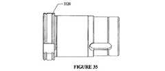
図37及び図38を参照すると、軸3702の実施形態は、2つのショルダ3704とウェスト3806とを有する細長い円筒本体から成る。ショルダ3704は、円筒本体の中点を越えた点に始まり、球101の穴を越えて延設される。図示されている実施形態のショルダ3704は面取りされていて、ブッシング3802の過度の摩耗を防止する手助けとなり、応力集中が減じられる。軸3702の両端は、脚103と接合するためのベアリングまたは他の手段と結合するように構成される。実施形態によっては、ショルダ3704は、脚103のためのサポート、停止装置及び/または公差基準点を提供することによって、ボールレッグ・アッセンブリ1670の組立を向上させる。特定の実施形態におけるウェスト3806は、オイル・リザーバとして機能する。この実施形態では、ブッシング3802は球101の穴内で軸3702を包囲する。他の実施形態では、ブッシング3802の代わりにベアリングが使用される。これらの実施形態では、ウェスト3806は、ベアリングが球101の内側に嵌合する場所で終わる。ベアリングは、ローラ・ベアリング、ドローン・カップ・ニードル・ベアリング、ケージ付きニードル・ローラ、ジャーナル・ベアリングまたはブッシングであってもよい。実施形態によっては、ベアリングはケージ付きニードル・ベアリングまたは他の保持ベアリングであることが好適である。一般的な摩擦ベアリングを使用する試みでは、CVT100、1500は、ベアリングまたはベアリングの転動体が軸3702、102に沿って球101からそれらが脚103を妨害して球101を止める場所まで移動することに起因して失敗、または停止する場合が多い。この移動は、操作中に球101を介して分散される力または歪み波によって引き起こされることが確信される。この理解は、広範な試験及び設計の結果として得られたものであり、出願人は、ケージ付きニードル・ローラまたは他の保持ベアリングの使用が、顕著かつ突如としてCVT100、1500の特定の実施形態の長寿命及び耐久性向上をもたらすものと考える。また、ブッシング及びジャーナル材料を使用する実施形態も、この現象に起因する失敗の低減に寄与する。ブッシング3802は、例えば、球101または軸3702の何れかまたは双方を被覆するバビット合金ライニングに換えられてもよい。さらに他の実施形態では、軸3702は青銅で製造され、ベアリング、ブッシングまたは他のライニングの必要なしに球101の座面を供給する。実施形態によっては、球101は、球101の穴の中央部に位置づけられるスペーサ(図示されていない)によって分離されるケージ付きニードル・ベアリングによって支持される。さらに、他の実施形態では、スペーサはショルダ3704に取り付けられ、ケージ付きニードル・ベアリングを脚103の構成要素から分離する。軸3702は、鋼、アルミニウム、マグネシウム、青銅または他の任意の金属または合金で製造されてもよい。特定の実施形態では、軸3702はプラスチックまたはセラミック材料で製造される。 With reference to FIGS. 37 and 38, the embodiment of
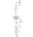
図41から43は、メイン・シャフト105の一実施形態を描いている。メイン・シャフト105は、シフト・ロッド112(図16及び40参照)を受け入れるための内側の穴4305を有する細長い物体である。CVT1500に実装されるように、メイン・シャフト105は、CVT1500の多くの構成要素のサポートとなる単体の軸である。メイン・シャフト105に単体の軸が使用される実施形態では、メイン・シャフト105は、CVT1500の特定の実施形態におけるトレランス・スタックを低減または排除する。さらに、複数片で構成される軸に比べて、単体であるメイン・シャフト105はCVT1500により高い剛性及び安定性をもたらす。 41-43 depict one embodiment of the
また、メイン・シャフト105は、シフト・ピン114を受け入れてその軸方向の移動、即ちメイン・シャフト105の長手軸に沿った移動を許容するスルー・スロット4204も含む。スロット4204のサイズは、CVT1500の特定のアプリケーションのレシオ・レンジを選択的に決定するためのシフト・ストップを供給するように選ばれてもよい。例えば、CVT1500は、スロット4204の適切な寸法及び/または位置決めを選ぶことによって、オーバードライブ・レンジより広いアンダードライブ・レンジ、またはその逆を有するように構成されてもよい。例示として、図42に示すスロット4204がCVT1500にとって可能なフル・シフト・レンジを提供するものとすれば、レシオ・レンジはスロット4204より短いスロットによって低減される。スロット4204が図42の右側で短縮されれば、アンダードライブ・レンジは低減されることになる。逆に、スロット4204が図42の左側で短縮されれば、オーバードライブ・レンジが低減される。 The
この実施形態では、フランジ4206及びショルダ4208はメイン・シャフト105から半径方向へ延設される。既に述べたように、フランジ4206及びショルダ4208は、ステータ1586のメイン・シャフト105への固定を容易にする。実施形態によっては、ステータ1586の穴は、ショルダ4208をなしですますことができるようにメイン・シャフト105へ取り付けられるようなサイズにされる。他の実施形態では、ショルダ4208及び/またはフランジ4206はメイン・シャフト105から分離された部品であってもよい。これらの例では、ショルダ4208及び/またはフランジ4206はメイン・シャフト105を中心として同軸的に取り付けられ、関連技術における任意の周知手段によってメイン・シャフト105に取り付けられる。図示されている実施形態では、メイン・シャフト105は、フランジ1610(図16参照)を回転可能式に固定するキー1606を受け入れるためのキー・シート4202を含む。キー1606は、半月キーであってもよい。幾つかの実施形態のメイン・シャフト105は、製造可能性、コスト、強度及び剛性の点で適切な金属で製造される。例えば、メイン・シャフトは鋼、マグネシウム、アルミニウムまたは他の金属または合金で製造されてもよい。 In this embodiment,
次に、特に図39及び40を参照して、上述のCVT1500の一実施形態を有するハブ1400の動作について説明する。フリーホイール1420は、自転車のチェーン(図示されていない)からトルクを受け取る。フリーホイール1420は、フリーホイール・キャリア1510に固定されることから、これにトルクを与え、フリーホイール・キャリア1510はこのトルクをキー・カップリング(図示されていない)を介して入力シャフト1505へ伝達する。メイン・シャフト105に取り付けられたニードル・ベアリング4010及び4020上に乗る入力シャフト1505は、入力シャフト1505のスプライン穴2710及びスプライン面2720及び3410を介してトルクをトーション・ディスク1525へ入力する。ニードル・ベアリング4010は、好適には、フリーホイール・キャリア1510及び/またはフリーホイール1420の近く、または下に置かれる。この配置は、入力シャフト1505に、フリーホイール・キャリア1510からのCVT1400を介する曲げ荷重としての半径方向荷重の伝達を防止する適切なサポートを提供する。さらに、実施形態によっては、ニードル・ベアリング4010及び4020間にスペーサ4030が供給される。スペーサ4030は、例えば、テフロンで製造されてもよい。 The operation of the
トーション・ディスク1525が回転すると、トーション・ディスク1525へ結合される負荷カム・ディスク1530がこの回転に従い、その結果、ランプ3610がローラ2504を活性化させる。ローラ2504は負荷カム・ディスク1540のランプ3610を昇り、負荷カム・ディスク1530と負荷カム・ディスク1540との間に挟まれる。ローラ2504のこの楔入により、トルク及び軸方向力は共に負荷カム・ディスク1530から負荷カム・ディスク1540へ伝達される。ローラ・ケージ1535は、ローラ2504を正しい配置構造で保持する働きをする。 As the
負荷カム・ディスク1540は入力ディスク1545へ固定的に結合されることから、負荷カム・ディスク1540は、軸方向力及びトルクの双方を入力ディスク1545へ伝達し、入力ディスク1545は、次にこの軸方向力及びトルクを摩擦接触を介して球101へ与える。入力ディスク1545が負荷カム・ディスク1540から受け取るトルク下で回転すると、入力ディスク1545と球101との摩擦接触により、軸3702を中心として球101を回転させる。この実施形態では、軸3702は、その固有の長手軸を中心とする球101との回転を制約されるが、軸3702は、シフト間のように球101の中心を中心として旋回または傾斜することができる。 Since the
入力ディスク1545、出力ディスク1560及びアイドラ1526は、球101と摩擦接触状態にある。球101が軸3702上で回転すると、球101は出力ディスク1560へトルクを与え、シャフト105を中心として出力ディスク1560を回転させる。出力ディスク1560はハブ・シェル138へ固定的に結合されることから、出力ディスク1560はハブ・シェル138へ出力トルクを与える。ハブ・シェル138は、メイン・シャフト105と同軸的に、かつメイン・シャフト105を中心として回転可能式に取り付けられる。ハブ・シェル138は、次に、出力トルクを自転車の車輪にスポーク等の周知方法を介して伝達する。
引き続き、図39及び40を参照すると、入力速度対出力速度比のシフト及び必然的に入力トルク対出力トルク比のシフトは、球101の回転軸を傾斜させることによって達成されるが、これは、軸3702の角度シフトの作動を必要とする。伝達比のシフトは、メイン・シャフト105における、または図3に示すシフト・ロッド312の回転におけるシフト・ロッド112の軸方向移動を作動させることを含む。シフト・ロッド112は、延設部1528内の穴1910を介してシフト・カム1527に接触しているピン114を軸方向へ並進させる。シフト・ピン114の軸方向移動は、シフト・カム1527の対応する軸方向移動を引き起こす。シフト・カム1527は脚103に(例えば、カム車152を介して)係合することから、脚103は、シフト・カムの輪郭2110に沿った移動に伴って半径方向へ移動する。脚103は軸3702へ連接されることから、脚103は、球101の中心を中心として軸3702を旋回させるレバーとして作用する。軸3702の旋回により、球101は回転軸を変更し、その結果、伝達比のシフトを引き起こす。With continued reference to FIGS. 39 and 40, the input speed to output speed ratio shift and necessarily the input torque to output torque ratio shift is achieved by tilting the rotational axis of the
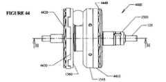
図44及び45は、入力ディスク1545に作用する1つの負荷カム・ディスク4440と、出力ディスク1560に作用する別の負荷カム・ディスク4420とを含む軸方向力生成機構を有するCVT4400の一実施形態を示す。この実施形態では、負荷カム・ディスク4440及び4420は、負荷カム・ディスク1530及び1540のランプ3610等のランプを組み込んでいる。この実施形態では、入力ディスク1545または出力ディスク1560の何れもランプを保有せず、またはランプを有するディスクへ結合されない。しかしながら、他の実施形態では、入力ディスク1545または出力ディスク1560の一方または双方にランプを有するディスクを供給すること、または入力ディスク1545及び/または出力ディスク1560内に負荷カム・ディスク4420、4440と共働するランプを形成することが望ましい場合がある。幾つかの実施形態のCVT4400は、さらに、負荷カム・ディスク4420と出力ディスク1560との間にあるローラ・セット(図示されていない)を収容しかつアラインするローラ・リテーナ4430を含む。図示されている実施形態では、ローラ・リテーナ4430は出力ディスク1560上を半径方向に案内する。同様に、負荷カム・ディスク4440と入力ディスク1545との間にもローラ・リテーナ4410が存在する。これらの実施形態に関連して説明しているローラ及びディスクは、先の軸方向力生成装置に関して既に述べたような任意のタイプまたは形状であってもよい。実施形態によっては、ランプ角度はディスクの表面から、1、2、3、4、5、6、7、8、9、10、11、12、13、14、15度またはこれ以上(またはこれらの間)の角度、もしくはこれらの何れかの間にある任意の角度で傾斜する。 44 and 45 illustrate one embodiment of a
図46は、ベアリング・ドラグの再循環効果を低下させるのに適した入力シャフト4605及びメイン・シャフト4625を有するCVT1600の一実施形態を示す。CVT100は、ニードル・ローラ・ベアリング4620により部分的に対抗される軸方向力を生成する軸方向力生成器165を含む。ハブ・キャップ4660は、ニードル・ローラ・ベアリング4620からのドラグ・トルク及び軸方向力に反作用する。他の実施形態では、ニードル・ローラ・ベアリング4620はボール・スラスト・ベアリングに交換され、かつ他の実施形態では、ボール・スラスト・ベアリングはニードル・ローラ・ベアリング4620の直径より小さい直径を有する。 FIG. 46 illustrates one embodiment of a
この実施形態では、メイン・シャフト4625は、例えばクリップであってもよいワッシャ4615の反動面を供給するショルダ4650を有する(実施形態によっては、これらは全て一体である)。入力シャフト4605は、ベアリング4645に反作用する延設部1410に嵌合される。ベアリング4645は、スラスト・ベアリングであってもよい。図に示すように、入力シャフト4605及びドライバ・ディスク(トーション・ディスク1525に類似するもの)は単体である。しかしながら、他の実施形態では、入力シャフト4605は、例えばねじ切り、キーイングまたは他の締結手段によってトーション・ディスク1525へ結合されてもよい。図示されている実施形態では、軸方向力の発生によって生じる反作用力の幾分かはメイン・シャフト4625に影響を与え、これにより、ベアリング・ドラグの再循環が低減される。さらに別の実施形態(図示されていない)では、延設部1410は、同じく入力シャフト4605をメイン・シャフト4625上で支持するアンギュラ・スラスト・ベアリングに反動される。この後者の実施形態では、ショルダ4650及びワッシャ4615は不要である。代わりに、メイン・シャフト4625がアンギュラ・スラスト・ベアリングを支持しかつ保持するように適することになる。 In this embodiment, the
本明細書に記述している多くの実施形態において、潤滑流体は、記述している多くの要素を支持するベアリングの摩擦を減じるために使用される。さらに、実施形態の中には、変速を介してトルクを伝達するトラクション・構成要素へより高いトラクション係数をもたらす流体の恩恵を受けるものがある。特定の実施形態における使用に適する「トラクション流体」と呼ばれるこのような流体には、Ashland oilから市販されているSantotrac 50、5CST AF、LubrizolのOS#155378、Exxon MobileのIVT Fluid #SL−2003B21−A及び他の任意の適切な潤滑剤が含まれる。実施形態によっては、トルク伝達構成要素のトラクション流体は、ベアリングを潤滑する潤滑剤とは別である。 In many embodiments described herein, the lubricating fluid is used to reduce the friction of the bearings that support the many elements described. Further, some embodiments benefit from fluids that provide a higher traction coefficient to traction components that transmit torque via a shift. Such fluids, referred to as “traction fluids” suitable for use in certain embodiments, include Santotrac 50, 5CST AF, Lubrizol OS # 155378, Exxon Mobile's IVT Fluid # SL-2003B21-, commercially available from Ashland oil. A and any other suitable lubricant are included. In some embodiments, the traction fluid of the torque transmitting component is separate from the lubricant that lubricates the bearing.
前述の説明は、本発明の特定の実施形態を詳述したものである。しかしながら、本明細書におけるこれまでの説明文が如何に詳細であろうと、本発明を多くの方法で実施できることは認識されるであろう。先に述べたように、本発明の特定の特徴または態様を説明する際の特定の用語法の使用では、本明細書においてその用語法が、その用語法が関連づけられている本発明の特徴または態様の任意の特有の特徴を包含すべく限定するように定義し直されていることを含意するものとして理解されるべきでない点は留意されなければならない。従って、本発明の範囲は、添付の特許請求の範囲及びその任意の等価物に従って解釈されるべきである。 The foregoing description details specific embodiments of the invention. It will be appreciated, however, that no matter how detailed the preceding description herein is, the invention can be implemented in many ways. As noted above, the use of a particular terminology in describing a particular feature or aspect of the present invention uses that terminology herein as a feature of the present invention with which the terminology is associated or It should be noted that it should not be understood as implying that it has been redefined to be limited to encompass any particular features of the aspects. Accordingly, the scope of the invention should be construed in accordance with the appended claims and any equivalents thereof.
Claims (14)
Translated fromJapanese前記CVTは、長手軸、ボールレッグ・アッセンブリ及びアイドラを含むアイドラ・アッセンブリを有し、
前記ボールレッグ・アッセンブリは、脚セットに結合される球及び前記球に形成される穴を介して延設され、両端部が前記脚に結合される球軸を備え、
各脚はカム車に結合され、
前記シフト・カム・ディスクは、
下記の形式、
θ=2×gamma_max×t−gamma_max
x=LEG×sin(θ)−0.5×ball_dia×RSF×θ×π/180+0.5×ARM×cos(θ)
y=LEG×cos(θ)−0.5×ARM×sin(θ)
ここで、前記球軸と前記長手軸とがなす傾斜角がgammaであり、
θは、gammaの最小値から最大値まで変化する変数であり、
gamma_maxは、gammaの最大値であり、
tは、0から1までの範囲で変わるパラメータ・レンジの変数であり、
x及びyは、前記カム車のx−y座標システムに対応する中心点を示す変数であり、
x軸は、前記長手軸に略平行であり、
LEGは、前記球軸から、対応する2つの前記カム車の中心を通る、前記球軸に平行な線までの垂直距離を示す値であり、
ball_diaは、前記球の直径を示す値であり、
RSFは、前記球と前記アイドラとの間の横方向のクリープを示す変数であり、
ARMは、前記カム車間の距離を示す値である
パラメータ方程式セットに従った基準曲線のx及びy値の面を備え、
前記カム車は、前記シフト・カム・ディスクの前記面に移動可能に乗るシフト・カム・ディスク。A shift cam disk for facilitating a ratio shift of a continuously variable transmission (CVT),
The CVT has an idler assembly including a longitudinal axis, a ball leg assembly, and an idler;
The ball leg assembly includes a sphere coupled to a leg set and a ball shaft extending through a hole formed in the sphere, and both ends coupled to the leg.
Each leg is connected to a cam car,
The shift cam disc is
The following format,
θ = 2 × gamma_max × t-gamma_max
x = LEG × sin (θ) −0.5 × ball_dia × RSF × θ × π / 180 + 0.5 × ARM × cos (θ)
y = LEG × cos (θ) −0.5 × ARM × sin (θ)
Here, aninclination angle formed by the spherical axis and the longitudinal axis is gamma,
θ isa variable thatvaries from the minimum value to the maximum value of gamma ,
gamma_max is the maximum value ofgamma ,
t is a variable of the parameter range that varies from 0 to 1,
x and y are variables indicating a center point corresponding to the xy coordinate system of the cam car,
the x-axis is substantially parallel to the longitudinal axis;
LEG is a value indicating a vertical distance from the spherical axis to a line parallel to the spherical axis passing through the centers of the two corresponding cam wheels,
ball_dia is a value indicating the diameter of the sphere,
RSF is a variable indicating lateral creep between the sphere and the idler;
ARM comprises x and y value planes of a reference curve according to a parameter equation set which is a value indicating the distance between the cam wheels,
The cam wheel is a shift cam disk that movably rides on the surface of the shift cam disk.
前記CVTは、長手軸、ボールレッグ・アッセンブリ及びアイドラを含むアイドラ・アッセンブリを有し、
前記ボールレッグ・アッセンブリは、脚セットに結合される球及び前記球に形成される穴を介して延設され、両端部が前記脚に結合される球軸を備え、
各脚はカム車に結合され、
前記方法は、
下記の形式、
θ=2×gamma_max×t−gamma_max
x=LEG×sin(θ)−0.5×ball_dia×RSF×θ×π/180+0.5×ARM×cos(θ)
y=LEG×cos(θ)−0.5×arm×sin(θ)
ここで、前記球軸と前記長手軸とがなす傾斜角がgammaであり、
θは、gammaの最小値から最大値まで変化する変数であり、
gamma_maxは、gammaの最大値であり、
tは、0から1までの範囲で変わるパラメータ・レンジの変数であり、
x及びyは、前記カム車のx−y座標システムに対応する中心点を示す変数であり、
x軸は、前記長手軸に略平行であり、
LEGは、前記球軸から、対応する2つの前記カム車の中心を通る、前記球軸に平行な線までの垂直距離を示す値であり、
ball_diaは、前記球の直径を示す値であり、
RSFは、前記球と前記アイドラとの間の横方向のクリープを示す変数であり、
ARMは、前記カム車間の距離を示す値である
パラメータ方程式セットに従って基準曲線を生成する工程と、
前記基準曲線のx及びy値に従って、前記カム車が移動可能に乗るシフト・カム・ディスク表面を形成する工程と、
を含む方法。A method of manufacturing a shift cam disk for facilitating a ratio shift of a continuously variable transmission (CVT) comprising:
The CVT has an idler assembly including a longitudinal axis, a ball leg assembly, and an idler;
The ball leg assembly includes a sphere coupled to a leg set and a ball shaft extending through a hole formed in the sphere, and both ends coupled to the leg.
Each leg is connected to a cam car,
The method
The following format,
θ = 2 × gamma_max × t-gamma_max
x = LEG × sin (θ) −0.5 × ball_dia × RSF × θ × π / 180 + 0.5 × ARM × cos (θ)
y = LEG × cos (θ) −0.5 × arm × sin (θ)
Here, aninclination angle formed by the spherical axis and the longitudinal axis is gamma,
θ isa variable thatvaries from the minimum value to the maximum value of gamma ,
gamma_max is the maximum value ofgamma ,
t is a variable of the parameter range that varies from 0 to 1,
x and y are variables indicating a center point corresponding to the xy coordinate system of the cam car,
the x-axis is substantially parallel to the longitudinal axis;
LEG is a value indicating a vertical distance from the spherical axis to a line parallel to the spherical axis passing through the centers of the two corresponding cam wheels,
ball_dia is a value indicating the diameter of the sphere,
RSF is a variable indicating lateral creep between the sphere and the idler;
ARM generates a reference curve according to a parameter equation set that is a value indicating the distance between the cam wheels;
Forming a shift cam disk surface on which the cam wheel is movably mounted according to the x and y values of the reference curve;
Including methods.
Applications Claiming Priority (2)
| Application Number | Priority Date | Filing Date | Title |
|---|---|---|---|
| US61639904P | 2004-10-05 | 2004-10-05 | |
| US60/616,399 | 2004-10-05 |
Related Parent Applications (1)
| Application Number | Title | Priority Date | Filing Date |
|---|---|---|---|
| JP2007535715ADivisionJP4974896B2 (en) | 2004-10-05 | 2005-10-03 | Continuously variable transmission |
Publications (3)
| Publication Number | Publication Date |
|---|---|
| JP2012117675A JP2012117675A (en) | 2012-06-21 |
| JP2012117675A5 JP2012117675A5 (en) | 2012-08-09 |
| JP5170484B2true JP5170484B2 (en) | 2013-03-27 |
Family
ID=36148799
Family Applications (3)
| Application Number | Title | Priority Date | Filing Date |
|---|---|---|---|
| JP2007535715AExpired - Fee RelatedJP4974896B2 (en) | 2004-10-05 | 2005-10-03 | Continuously variable transmission |
| JP2011128425AExpired - LifetimeJP4918169B2 (en) | 2004-10-05 | 2011-06-08 | Continuously variable transmission |
| JP2012001171AExpired - Fee RelatedJP5170484B2 (en) | 2004-10-05 | 2012-01-06 | Continuously variable transmission |
Family Applications Before (2)
| Application Number | Title | Priority Date | Filing Date |
|---|---|---|---|
| JP2007535715AExpired - Fee RelatedJP4974896B2 (en) | 2004-10-05 | 2005-10-03 | Continuously variable transmission |
| JP2011128425AExpired - LifetimeJP4918169B2 (en) | 2004-10-05 | 2011-06-08 | Continuously variable transmission |
Country Status (14)
| Country | Link |
|---|---|
| US (20) | US7762919B2 (en) |
| EP (2) | EP1815165B1 (en) |
| JP (3) | JP4974896B2 (en) |
| KR (3) | KR101276082B1 (en) |
| CN (1) | CN101166922B (en) |
| AT (1) | ATE550573T1 (en) |
| AU (1) | AU2005294611B2 (en) |
| BR (1) | BRPI0516562A (en) |
| CA (2) | CA2582562C (en) |
| DK (1) | DK1815165T3 (en) |
| MX (3) | MX2007003828A (en) |
| PL (1) | PL1815165T3 (en) |
| TW (1) | TWI309700B (en) |
| WO (1) | WO2006041718A2 (en) |
Families Citing this family (118)
| Publication number | Priority date | Publication date | Assignee | Title |
|---|---|---|---|---|
| US6551210B2 (en)* | 2000-10-24 | 2003-04-22 | Motion Technologies, Llc. | Continuously variable transmission |
| KR100854795B1 (en)* | 2001-04-26 | 2008-08-27 | 모션 테크놀로지즈 엘엘씨 | Device for speed ratio adjustment of roller traction transmission and continuous variable transmission |
| US7011600B2 (en) | 2003-02-28 | 2006-03-14 | Fallbrook Technologies Inc. | Continuously variable transmission |
| US7166052B2 (en) | 2003-08-11 | 2007-01-23 | Fallbrook Technologies Inc. | Continuously variable planetary gear set |
| EP1774199B1 (en)* | 2004-07-21 | 2013-06-12 | Fallbrook Intellectual Property Company LLC | Rolling traction planetary drive |
| WO2006041718A2 (en)* | 2004-10-05 | 2006-04-20 | Fallbrook Technologies, Inc. | Continuously variable transmission |
| WO2007044128A2 (en) | 2005-08-22 | 2007-04-19 | Viryd Technologies Inc. | Fluid energy converter |
| US7670243B2 (en)* | 2005-08-24 | 2010-03-02 | Fallbrook Technologies, Inc. | Continuously variable transmission |
| WO2007070167A2 (en) | 2005-10-28 | 2007-06-21 | Fallbrook Technologies Inc. | Electromotive drives |
| PL1954959T3 (en) | 2005-11-22 | 2013-10-31 | Fallbrook Ip Co Llc | Continuously variable transmission |
| CN102221073B (en)* | 2005-12-09 | 2013-03-27 | 福博科技术公司 | Continuously variable transmission |
| EP1811202A1 (en)* | 2005-12-30 | 2007-07-25 | Fallbrook Technologies, Inc. | A continuously variable gear transmission |
| US7882762B2 (en) | 2006-01-30 | 2011-02-08 | Fallbrook Technologies Inc. | System for manipulating a continuously variable transmission |
| WO2007106874A2 (en) | 2006-03-14 | 2007-09-20 | Autocraft Industries, Inc. | Improved wheelchair |
| US20080070729A1 (en)* | 2006-05-11 | 2008-03-20 | Fallbrook Technologies Inc. | Continuously variable drivetrain |
| CN102269055B (en) | 2006-06-26 | 2013-08-28 | 福博科技术公司 | Continuously variable transmission |
| PL2089642T3 (en) | 2006-11-08 | 2013-09-30 | Fallbrook Ip Co Llc | Clamping force generator |
| EP2125469A2 (en) | 2007-02-01 | 2009-12-02 | Fallbrook Technologies Inc. | System and methods for control of transmission and/or prime mover |
| GB0702490D0 (en)* | 2007-02-09 | 2007-03-21 | Torotrak Dev Ltd | CVT control system |
| US20100093479A1 (en) | 2007-02-12 | 2010-04-15 | Fallbrook Technologies Inc. | Continuously variable transmissions and methods therefor |
| TWI461615B (en) | 2007-02-16 | 2014-11-21 | Fallbrook Ip Co Llc | Infinitely variable transmissions, continuously variable transmissions, methods, assemblies, subassemblies, and components therefor |
| EP2142826B1 (en) | 2007-04-24 | 2015-10-28 | Fallbrook Intellectual Property Company LLC | Electric traction drives |
| US8641577B2 (en) | 2007-06-11 | 2014-02-04 | Fallbrook Intellectual Property Company Llc | Continuously variable transmission |
| CN103697120B (en) | 2007-07-05 | 2017-04-12 | 福博科技术公司 | Continuously variable transmission |
| US7887032B2 (en)* | 2007-11-07 | 2011-02-15 | Fallbrook Technologies Inc. | Self-centering control rod |
| CN103939602B (en) | 2007-11-16 | 2016-12-07 | 福博科知识产权有限责任公司 | Controllers for variable speed drives |
| US7878935B2 (en)* | 2007-11-26 | 2011-02-01 | Derek Lahr | Continuously variable transmission with external cam |
| US8321097B2 (en) | 2007-12-21 | 2012-11-27 | Fallbrook Intellectual Property Company Llc | Automatic transmissions and methods therefor |
| US8313405B2 (en) | 2008-02-29 | 2012-11-20 | Fallbrook Intellectual Property Company Llc | Continuously and/or infinitely variable transmissions and methods therefor |
| US8317651B2 (en) | 2008-05-07 | 2012-11-27 | Fallbrook Intellectual Property Company Llc | Assemblies and methods for clamping force generation |
| CN102112778B (en) | 2008-06-06 | 2013-10-16 | 福博科技术公司 | Infinitely variable transmission, continuously variable transmission, methods, assemblies, subassemblies and components therefor |
| CN103438165B (en)* | 2008-06-06 | 2016-08-17 | 福博科技术公司 | Unlimited formula buncher, buncher, for its method, assembly, sub-component and parts |
| EP2304272B1 (en) | 2008-06-23 | 2017-03-08 | Fallbrook Intellectual Property Company LLC | Continuously variable transmission |
| CN104019201B (en)* | 2008-06-23 | 2017-07-28 | 福博科知识产权有限责任公司 | Buncher |
| CA2732668C (en) | 2008-08-05 | 2017-11-14 | Fallbrook Technologies Inc. | Methods for control of transmission and prime mover |
| US8469856B2 (en)* | 2008-08-26 | 2013-06-25 | Fallbrook Intellectual Property Company Llc | Continuously variable transmission |
| US8167759B2 (en) | 2008-10-14 | 2012-05-01 | Fallbrook Technologies Inc. | Continuously variable transmission |
| CN104019200B (en)* | 2008-10-14 | 2017-07-14 | 福博科知识产权有限责任公司 | Buncher |
| US9464701B2 (en)* | 2009-01-22 | 2016-10-11 | Orbital Traction, Ltd. | Fluid movement systems including a continuously variable transmission |
| ES2439647T3 (en) | 2009-04-16 | 2014-01-24 | Fallbrook Intellectual Property Company Llc | Stator set and speed change mechanism for a continuously variable transmission |
| US20120025644A1 (en)* | 2009-04-21 | 2012-02-02 | Toyota Jidosha Kabushiki Kaisha | Electric motor having speed change function |
| US9151269B2 (en) | 2009-07-20 | 2015-10-06 | Differential Dynamics Corporation | Run-of-the-river or ocean current turbine |
| US8512195B2 (en) | 2010-03-03 | 2013-08-20 | Fallbrook Intellectual Property Company Llc | Infinitely variable transmissions, continuously variable transmissions, methods, assemblies, subassemblies, and components therefor |
| DE112010005401B8 (en)* | 2010-03-18 | 2014-11-13 | Toyota Jidosha Kabushiki Kaisha | Continuously variable transmission |
| GB2488506A (en) | 2010-04-15 | 2012-09-05 | Orbital Traction Ltd A Texas Ltd Partnership | Continuously variable transmission with non-linear end clamping force |
| US9631563B2 (en) | 2010-06-30 | 2017-04-25 | Orbital Traction, Ltd | Torque pulse dampener |
| US9912209B2 (en) | 2010-07-20 | 2018-03-06 | Differential Dynamics Corporation | Renewable energy marine hydrokinetic or wind turbine |
| US9476401B2 (en) | 2010-07-20 | 2016-10-25 | Differential Dynamics Corporation | Marine hydrokinetic turbine |
| US8888643B2 (en) | 2010-11-10 | 2014-11-18 | Fallbrook Intellectual Property Company Llc | Continuously variable transmission |
| AU2012240435B2 (en) | 2011-04-04 | 2016-04-28 | Fallbrook Intellectual Property Company Llc | Auxiliary power unit having a continuously variable transmission |
| US9707138B2 (en) | 2011-07-27 | 2017-07-18 | The Board Of Trustees Of The University Of Illinois | Gear-shifting system for manually propelled wheelchairs |
| US8956262B2 (en) | 2011-09-22 | 2015-02-17 | Toyota Jidosha Kabushiki Kaisha | Continuously variable transmission |
| GB201120227D0 (en)* | 2011-11-23 | 2012-01-04 | Crompton Technology Group Ltd | Composite material component |
| US8613235B2 (en)* | 2011-12-02 | 2013-12-24 | Carlos Raul Espinosa-Montalvo | Continuously variable transmission |
| KR101251617B1 (en)* | 2011-12-21 | 2013-04-08 | 남부대학교산학협력단 | Stepless transmission type spherical frictional |
| GB201200357D0 (en)* | 2012-01-10 | 2012-02-22 | Torotrak Dev Ltd | Variator |
| US9090312B2 (en) | 2012-01-12 | 2015-07-28 | Shimano Inc. | Continuously variable bicycle transmission |
| US9347532B2 (en) | 2012-01-19 | 2016-05-24 | Dana Limited | Tilting ball variator continuously variable transmission torque vectoring device |
| CN104302949B (en) | 2012-01-23 | 2017-05-03 | 福博科知识产权有限责任公司 | Infinitely variable continuously variable transmission, continuously variable continuously variable transmission, method, assembly, subassembly, and parts thereof |
| CN104204615B (en) | 2012-02-15 | 2017-10-24 | 德纳有限公司 | Transmission device and the power train with tilt ball speed changer infinitely variable speed transmission |
| WO2013125041A1 (en)* | 2012-02-24 | 2013-08-29 | トヨタ自動車株式会社 | Continuously variable transmission |
| JP5590265B2 (en)* | 2012-03-09 | 2014-09-17 | トヨタ自動車株式会社 | Continuously variable transmission |
| US8939866B2 (en)* | 2012-03-15 | 2015-01-27 | Hamilton Sundstrand Corporation | Toroidal traction drive |
| EP2893219A4 (en) | 2012-09-06 | 2016-12-28 | Dana Ltd | Transmission having a continuously or infinitely variable variator drive |
| WO2014039438A2 (en)* | 2012-09-06 | 2014-03-13 | Dana Limited | Cvt variator ball and method of construction thereof |
| WO2014039713A1 (en) | 2012-09-07 | 2014-03-13 | Dana Limited | Ivt based on a ball type cvp including powersplit paths |
| WO2014039708A1 (en) | 2012-09-07 | 2014-03-13 | Dana Limited | Ball type cvt including a direct drive mode |
| US9689477B2 (en) | 2012-09-07 | 2017-06-27 | Dana Limited | Ball type continuously variable transmission/infinitely variable transmission |
| CN104768787A (en) | 2012-09-07 | 2015-07-08 | 德纳有限公司 | Ball type CVT with powersplit paths |
| US9599204B2 (en) | 2012-09-07 | 2017-03-21 | Dana Limited | Ball type CVT with output coupled powerpaths |
| JP6320386B2 (en) | 2012-09-07 | 2018-05-09 | デーナ リミテッド | Ball type CVT / IVT including planetary gear set |
| JP5590098B2 (en) | 2012-10-31 | 2014-09-17 | トヨタ自動車株式会社 | Continuously variable transmission |
| US10030748B2 (en) | 2012-11-17 | 2018-07-24 | Dana Limited | Continuously variable transmission |
| CN103887263B (en)* | 2012-12-21 | 2016-12-28 | 碁鼎科技秦皇岛有限公司 | Encapsulating structure and preparation method thereof |
| US9005068B2 (en)* | 2012-12-21 | 2015-04-14 | Shimano Inc. | Continuously variable bicycle transmission mechanism and bicycle hub |
| US9429217B2 (en) | 2013-01-28 | 2016-08-30 | Robert Hornblower Meyer | Continuously variable drive mechanism |
| WO2014124063A1 (en) | 2013-02-08 | 2014-08-14 | Microsoft Corporation | Pervasive service providing device-specific updates |
| US20140235385A1 (en)* | 2013-02-21 | 2014-08-21 | Armin Sebastian Tay | Cone with member cvt for which belt tension can be reduced |
| US9551404B2 (en) | 2013-03-14 | 2017-01-24 | Dana Limited | Continuously variable transmission and an infinitely variable transmission variator drive |
| CN105121905A (en) | 2013-03-14 | 2015-12-02 | 德纳有限公司 | Ball type continuously variable transmission |
| US8814739B1 (en) | 2013-03-14 | 2014-08-26 | Team Industries, Inc. | Continuously variable transmission with an axial sun-idler controller |
| US8827856B1 (en) | 2013-03-14 | 2014-09-09 | Team Industries, Inc. | Infinitely variable transmission with an IVT stator controlling assembly |
| US9322461B2 (en) | 2013-03-14 | 2016-04-26 | Team Industries, Inc. | Continuously variable transmission with input/output planetary ratio assembly |
| US9133918B2 (en) | 2013-03-14 | 2015-09-15 | Team Industries, Inc. | Continuously variable transmission with differential controlling assemblies |
| US9057439B2 (en) | 2013-03-14 | 2015-06-16 | Team Industries, Inc. | Infinitely variable transmission with IVT traction ring controlling assemblies |
| JP5621872B2 (en) | 2013-04-04 | 2014-11-12 | トヨタ自動車株式会社 | Continuously variable transmission |
| KR102433297B1 (en) | 2013-04-19 | 2022-08-16 | 폴브룩 인텔렉츄얼 프로퍼티 컴퍼니 엘엘씨 | Continuously variable transmission |
| EP3004686B1 (en) | 2013-06-06 | 2018-08-08 | Dana Limited | 3-mode front wheel drive and rear wheel drive continuously variable planetary transmission |
| JP2015017664A (en)* | 2013-07-11 | 2015-01-29 | 日本精工株式会社 | Electric vehicle drive |
| JP2015075185A (en)* | 2013-10-10 | 2015-04-20 | 日本精工株式会社 | Single cavity type toroidal type continuously variable transmission |
| WO2015073948A2 (en) | 2013-11-18 | 2015-05-21 | Dana Limited | Torque peak detection and control mechanism for cvp |
| US10030751B2 (en) | 2013-11-18 | 2018-07-24 | Dana Limited | Infinite variable transmission with planetary gear set |
| JP6003943B2 (en)* | 2014-04-28 | 2016-10-05 | トヨタ自動車株式会社 | Hybrid vehicle and control method of hybrid vehicle |
| ES2554181B1 (en)* | 2014-06-12 | 2016-06-09 | José Antonio CARAMÉS JIMÉNEZ | Continuously Variable Automatic Transmission |
| CN106536987A (en) | 2014-06-17 | 2017-03-22 | 德纳有限公司 | Off-highway continuously variable planetary-based multimore transmission including infinite variable transmission and direct continuously variable tranmission |
| JP6408327B2 (en)* | 2014-09-30 | 2018-10-17 | 日本電産シンポ株式会社 | Friction type continuously variable transmission |
| JP6241427B2 (en)* | 2015-01-27 | 2017-12-06 | トヨタ自動車株式会社 | Hybrid vehicle |
| US9719581B2 (en)* | 2015-03-19 | 2017-08-01 | Allison Transmission, Inc. | Variator stator functional and manufacturing improvements |
| WO2016164026A1 (en)* | 2015-04-09 | 2016-10-13 | Allison Transmission Inc. | Continuously variable planetary transmission |
| US11078812B2 (en) | 2015-07-13 | 2021-08-03 | Borgwarner Inc. | Continuously variable friction drive phaser |
| US10035511B2 (en)* | 2015-07-27 | 2018-07-31 | Cummins Inc. | Method and system for controlling operation of an engine powered device having cyclical duty cycles |
| CN108138929A (en)* | 2015-08-11 | 2018-06-08 | 德纳有限公司 | Hydraulic speed ratio control method for vehicle having ball-shift continuously variable transmission |
| US10030594B2 (en) | 2015-09-18 | 2018-07-24 | Dana Limited | Abuse mode torque limiting control method for a ball-type continuously variable transmission |
| US10047861B2 (en) | 2016-01-15 | 2018-08-14 | Fallbrook Intellectual Property Company Llc | Systems and methods for controlling rollback in continuously variable transmissions |
| KR102364407B1 (en) | 2016-03-18 | 2022-02-16 | 폴브룩 인텔렉츄얼 프로퍼티 컴퍼니 엘엘씨 | continuously variable transmission system and method |
| US10023266B2 (en) | 2016-05-11 | 2018-07-17 | Fallbrook Intellectual Property Company Llc | Systems and methods for automatic configuration and automatic calibration of continuously variable transmissions and bicycles having continuously variable transmissions |
| US10253881B2 (en)* | 2016-05-20 | 2019-04-09 | Fallbrook Intellectual Property Company Llc | Systems and methods for axial force generation |
| JP6773297B2 (en) | 2016-10-14 | 2020-10-21 | 日本電産シンポ株式会社 | Continuously variable transmission and bicycle |
| US10253857B2 (en) | 2017-01-31 | 2019-04-09 | Dana Heavy Vehicle Systems Group, Llc | Multi-speed electric transaxle unit with co-axial shafts |
| TWI868953B (en)* | 2017-05-30 | 2025-01-01 | 日商島野股份有限公司 | Bicycle rear hub assembly and sprocket support body |
| CN107559398A (en)* | 2017-07-26 | 2018-01-09 | 江苏创斯达科技有限公司 | A kind of drive mechanism |
| US10400882B2 (en) | 2017-10-18 | 2019-09-03 | Deere & Company | Product and method of assembling multiple components using a press fit |
| US11215268B2 (en) | 2018-11-06 | 2022-01-04 | Fallbrook Intellectual Property Company Llc | Continuously variable transmissions, synchronous shifting, twin countershafts and methods for control of same |
| MX2021003494A (en) | 2018-12-27 | 2021-06-18 | Differential Dynamics Corp | Scalable and efficient mechanical speed converter-controlled wind and hydrokinetic turbines. |
| WO2020176392A1 (en) | 2019-02-26 | 2020-09-03 | Fallbrook Intellectual Property Company Llc | Reversible variable drives and systems and methods for control in forward and reverse directions |
| US11808326B2 (en)* | 2019-09-04 | 2023-11-07 | Aidan McAnulla | Infinitely variable multi-epicyclic friction transmission system for electric motor |
| CN112621244B (en)* | 2020-12-22 | 2021-12-10 | 浙江高金电子科技有限责任公司 | Cutting, chamfering and welding integrated machine for machining automobile air conditioner pipe fitting |
| TWI854587B (en)* | 2023-04-10 | 2024-09-01 | 龍宸有限公司 | Structure of pulley set for motorcycle |
Family Cites Families (680)
| Publication number | Priority date | Publication date | Assignee | Title |
|---|---|---|---|---|
| USRE22761E (en) | 1946-05-28 | Transmission | ||
| GB592320A (en) | 1945-03-13 | 1947-09-15 | Frederick Whigham Mcconnel | Improvements in or relating to variable speed-gears |
| US1121210A (en) | 1914-12-15 | Fried Krupp Germaniawerft Ag | Submarine boat. | |
| US2675713A (en) | 1954-04-20 | Protective mechanism for variable | ||
| US719595A (en) | 1901-07-06 | 1903-02-03 | Jacob B Huss | Bicycle driving mechanism. |
| US1207985A (en) | 1914-08-17 | 1916-12-12 | Charles I Null | Antifriction-hanger. |
| US1175677A (en) | 1914-10-24 | 1916-03-14 | Roderick Mcclure | Power-transmitting device. |
| US1234567A (en)* | 1915-09-14 | 1917-07-24 | Edward J Quigley | Soft collar. |
| US1380006A (en) | 1917-08-04 | 1921-05-31 | Hamilton Beach Mfg Co | Variable-speed transmission |
| JP3223241B2 (en)* | 1997-03-17 | 2001-10-29 | 本田技研工業株式会社 | Belt type continuously variable transmission |
| US1390971A (en)* | 1921-01-24 | 1921-09-13 | Samain Pierre | Gearing |
| US1579359A (en)* | 1921-10-06 | 1926-04-06 | Charles B Rose | Clutch |
| US1588222A (en)* | 1923-08-17 | 1926-06-08 | Jr Henry D Olier | Lighting device |
| US1558222A (en) | 1924-01-14 | 1925-10-20 | Beetow Albert | Backlash take-up for gears |
| US1629902A (en) | 1924-08-07 | 1927-05-24 | Arter Jakob | Power-transmitting device |
| CH118064A (en) | 1924-08-07 | 1926-12-16 | Jakob Arter | Friction change transmission. |
| US1686446A (en) | 1926-04-15 | 1928-10-02 | John A Gilman | Planetary transmission mechanism |
| FR620375A (en) | 1926-06-24 | 1927-04-21 | Automatic pressure device for friction plates | |
| US1774254A (en) | 1927-06-28 | 1930-08-26 | John F Daukus | Clutch mechanism |
| US1692902A (en) | 1927-09-01 | 1928-11-27 | James T Moltrup | Die and method of drawing shapes |
| US1903228A (en) | 1927-10-21 | 1933-03-28 | Gen Motors Corp | Frictional gearing |
| DE498701C (en) | 1927-11-18 | 1930-05-31 | Jakob Arter | Friction ball change gear |
| US1865102A (en)* | 1929-05-07 | 1932-06-28 | Frank A Hayes | Variable speed transmission mechanism |
| US1793571A (en)* | 1929-12-14 | 1931-02-24 | Frank O Vaughn | Variable-speed drive |
| US1847027A (en)* | 1930-02-19 | 1932-02-23 | Thomsen Thomas Peter | Change-speed gear |
| US1978439A (en) | 1930-04-01 | 1934-10-30 | John S Sharpe | Variable transmission |
| US1850189A (en) | 1930-07-16 | 1932-03-22 | Carl W Weiss | Transmission device |
| GB391448A (en) | 1930-08-02 | 1933-04-27 | Frank Anderson Hayes | Improvements in or relating to friction transmission |
| US1937234A (en)* | 1931-04-28 | 1933-11-28 | Raymond P Lansing | Driving mechanism |
| US1858696A (en) | 1931-07-08 | 1932-05-17 | Carl W Weiss | Transmission |
| US2131158A (en) | 1932-02-03 | 1938-09-27 | Gen Motors Corp | Continuously variable transmission |
| US2086491A (en) | 1932-04-11 | 1937-07-06 | Adiel Y Dodge | Variable speed transmission |
| US2123008A (en)* | 1932-06-18 | 1938-07-05 | Frank A Hayes | Power transmission mechanism |
| US2109845A (en) | 1932-07-23 | 1938-03-01 | Erban Operating Corp | Power transmission mechanism |
| US2097631A (en)* | 1932-12-09 | 1937-11-02 | Erban Operating Corp | Power transmission mechanism |
| US1965102A (en)* | 1933-01-18 | 1934-07-03 | Carolyn M Jerome | Air heating apparatus |
| US2196064A (en) | 1933-02-04 | 1940-04-02 | Erban Patents Corp | Driving energy consumer |
| US2060884A (en) | 1933-09-19 | 1936-11-17 | Erban Operating Corp | Power transmission mechanism |
| US2112763A (en) | 1933-12-28 | 1938-03-29 | Cloudsley John Leslie | Variable speed power transmission mechanism |
| US2030203A (en)* | 1934-05-31 | 1936-02-11 | Gen Motors Corp | Torque loading lash adjusting device for friction roller transmissions |
| US2134225A (en) | 1935-03-13 | 1938-10-25 | Christiansen Ejnar | Variable speed friction gear |
| US2152796A (en) | 1935-03-13 | 1939-04-04 | Erban Patents Corp | Variable speed transmission |
| US2100629A (en)* | 1936-07-18 | 1937-11-30 | Chilton Roland | Transmission |
| US2209254A (en) | 1938-07-29 | 1940-07-23 | Yrjo A Ahnger | Friction transmission device |
| US2259933A (en) | 1939-02-20 | 1941-10-21 | John O Holloway | Clutch coupling for motor vehicles |
| US2325502A (en)* | 1940-03-08 | 1943-07-27 | Georges Auguste Felix | Speed varying device |
| US2269434A (en) | 1940-11-18 | 1942-01-13 | Cuyler W Brooks | Automatic transmission mechanism |
| US2595367A (en) | 1943-11-09 | 1952-05-06 | Picanol Jaime | Toroidal variable-speed gear drive |
| US2480968A (en) | 1944-08-30 | 1949-09-06 | Ronai Ernest | Variable transmission means |
| US2469653A (en) | 1945-02-01 | 1949-05-10 | Kopp Jean | Stepless variable change-speed gear with roller bodies |
| US2480988A (en)* | 1945-02-06 | 1949-09-06 | Albert E Walton | Window sash lock |
| US2461258A (en) | 1946-06-06 | 1949-02-08 | Cuyler W Brooks | Automatic transmission mechanism |
| US2596538A (en) | 1946-07-24 | 1952-05-13 | Allen A Dicke | Power transmission |
| US2553465A (en) | 1946-11-30 | 1951-05-15 | Monge Jean Raymond Barthelemy | Manual or power-operated planetary transmission |
| NL82920C (en) | 1948-04-17 | |||
| US2586725A (en) | 1950-02-08 | 1952-02-19 | Roller Gear Corp | Variable-speed transmission |
| US2696888A (en) | 1951-05-26 | 1954-12-14 | Curtiss Wright Corp | Propeller having variable ratio transmission for changing its pitch |
| US2716357A (en) | 1952-07-07 | 1955-08-30 | Rennerfelt Sven Bernhard | Continuously variable speed gears |
| US2730904A (en) | 1952-07-14 | 1956-01-17 | Rennerfelt Sven Bernhard | Continuously variable speed gears |
| US2746614A (en)* | 1952-07-18 | 1956-05-22 | Paxton Mitchell Company | Safety uncoupling rigging for locomotive draft gear |
| US2748614A (en) | 1953-06-23 | 1956-06-05 | Zenas V Weisel | Variable speed transmission |
| US2901924A (en) | 1954-08-05 | 1959-09-01 | New Prod Corp | Accessory drive |
| US2873911A (en) | 1955-05-26 | 1959-02-17 | Librascope Inc | Mechanical integrating apparatus |
| US2868038A (en) | 1955-05-26 | 1959-01-13 | Liquid Controls Corp | Infinitely variable planetary transmission |
| US2913932A (en) | 1955-10-04 | 1959-11-24 | Mcculloch Motors Corp | Variable speed planetary type drive |
| US2874592A (en) | 1955-11-07 | 1959-02-24 | Mcculloch Motors Corp | Self-controlled variable speed planetary type drive |
| US2871714A (en)* | 1956-01-30 | 1959-02-03 | Zenas V Weisel | Automotive transmission |
| US2959063A (en) | 1956-09-11 | 1960-11-08 | Perbury Engineering Ltd | Infinitely variable change speed gears |
| US2891213A (en) | 1956-10-30 | 1959-06-16 | Electric Control Corp | Constant frequency variable input speed alternator apparatuses |
| US2950149A (en) | 1957-01-29 | 1960-08-23 | John B Thomson | Relatively reciprocable shaft and bearing |
| US2931235A (en) | 1957-11-12 | 1960-04-05 | George Cohen 600 Group Ltd | Variable speed friction drive transmissions |
| US2931234A (en) | 1957-11-12 | 1960-04-05 | George Cohen 600 Group Ltd | Variable speed friction drive trans-mission units |
| US2883883A (en)* | 1957-11-13 | 1959-04-28 | Curtiss Wright Corp | Variable speed transmission |
| US2964959A (en) | 1957-12-06 | 1960-12-20 | Gen Motors Corp | Accessory drive transmission |
| DE1171692B (en) | 1958-01-09 | 1964-06-04 | Fabrications Unicum Soc D | Friction gear with several flat friction discs |
| BE574149A (en) | 1958-01-09 | 1959-04-16 | Fabrications Unicum Soc D | Pressure device of friction speed variators |
| US3048056A (en) | 1958-04-10 | 1962-08-07 | Gen Motors Corp | Drive system |
| US3035460A (en) | 1958-12-02 | 1962-05-22 | Guichard Louis | Automatic infinitely variablespeed drive |
| US2959070A (en) | 1959-01-09 | 1960-11-08 | Borg Warner | Accessory drive |
| US2959972A (en) | 1959-02-11 | 1960-11-15 | Avco Mfg Corp | Single ball joint roller support for toroidal variable ratio transmissions |
| US3051020A (en)* | 1959-02-16 | 1962-08-28 | Thornton Axle Inc | Locking differential with pressure relief device |
| US3008061A (en) | 1959-04-21 | 1961-11-07 | Barden Corp | Slow speed motor |
| US2949800A (en)* | 1959-05-11 | 1960-08-23 | Neuschotz Robert | Tool for installing threaded elements |
| US3248960A (en) | 1959-11-13 | 1966-05-03 | Roller Gear Ltd | Variable speed drive transmission |
| DE1178259B (en) | 1959-12-03 | 1964-09-17 | Motoren Werke Mannheim Ag | Main and secondary connecting rod for V machines |
| US3204476A (en) | 1960-04-05 | 1965-09-07 | William S Rouverol | Variable speed transmission |
| US3237468A (en) | 1960-05-13 | 1966-03-01 | Roller Gear Ltd | Variable speed drive transmission |
| US3246531A (en) | 1960-11-04 | 1966-04-19 | Kashihara Manabu | Infinitely variable speed change gear |
| DE1217166B (en) | 1960-11-04 | 1966-05-18 | Manabu Kashihara | Ball friction gear with swiveling balls |
| BE629125A (en) | 1961-03-08 | |||
| US3229538A (en) | 1961-09-25 | 1966-01-18 | Roller Gear Ltd | Variable speed drive transmission |
| US3154957A (en) | 1961-10-16 | 1964-11-03 | Kashihara Manabu | Infinitely variable speed change gear utilizing a ball |
| US3086704A (en) | 1961-11-24 | 1963-04-23 | Ryan Aeronautical Co | Cosine-secant multiplier |
| US3087248A (en)* | 1962-09-10 | 1963-04-30 | Clary Corp | Strip measuring and marking apparatus |
| CH398236A (en) | 1962-09-20 | 1965-08-31 | Yamamoto Sota | Friction stepless speed variator |
| US3216283A (en) | 1963-03-04 | 1965-11-09 | Ford Motor Co | Variable speed torque transmitting means |
| US3283614A (en) | 1963-04-10 | 1966-11-08 | Gen Motors Corp | Friction drive mechanism |
| US3163050A (en) | 1963-06-19 | 1964-12-29 | Excelermatic | Toroidal transmission bearing means |
| US3211364A (en)* | 1963-10-30 | 1965-10-12 | Lau Blower Co | Blower wheel |
| US3184983A (en)* | 1963-10-30 | 1965-05-25 | Excelermatic | Toroidal transmission mechanism with torque loading cam means |
| FR1376401A (en)* | 1963-12-05 | 1964-10-23 | Fabrications Unicum Soc D | Improvements to the adjustment device of friction speed variators in particular |
| US3258981A (en)* | 1963-12-30 | 1966-07-05 | Ford Motor Co | Infinitely variable speed friction drive |
| JPS441098Y1 (en) | 1964-12-24 | 1969-01-17 | ||
| JPS422843Y1 (en) | 1965-01-18 | 1967-02-20 | ||
| US3273468A (en) | 1965-01-26 | 1966-09-20 | Fawick Corp | Hydraulic system with regenerative position |
| JPS422844Y1 (en) | 1965-02-06 | 1967-02-20 | ||
| JPS413126Y1 (en) | 1965-08-04 | 1966-02-23 | ||
| US3340895A (en) | 1965-08-27 | 1967-09-12 | Sanders Associates Inc | Modular pressure regulating and transfer valve |
| GB1119988A (en) | 1965-10-14 | 1968-07-17 | Nat Res Dev | Transmission system for interconnecting two rotary machines |
| US3464281A (en) | 1965-10-27 | 1969-09-02 | Hiroshi Azuma | Friction-type automatic variable speed means |
| GB1132473A (en) | 1965-11-15 | 1968-11-06 | James Robert Young | Variable ratio friction transmission and control system therefor |
| US3280646A (en) | 1966-02-02 | 1966-10-25 | Ford Motor Co | Control system for an infinitely variable speed friction drive |
| GB1135141A (en) | 1966-07-04 | 1968-11-27 | Self Changing Gears Ltd | Improved auxiliary overdrive gear |
| JPS47448B1 (en) | 1966-07-08 | 1972-01-07 | ||
| US3430504A (en) | 1966-08-29 | 1969-03-04 | Gen Motors Corp | Transmission |
| GB1195205A (en) | 1966-09-12 | 1970-06-17 | Nat Res Dev | Improvements in or relating to Toroidal Race Transmission Units. |
| SE316664B (en) | 1966-11-30 | 1969-10-27 | B Gustavsson | |
| US3407687A (en) | 1967-03-27 | 1968-10-29 | Hayashi Tadashi | Variable ratio power transmission device |
| JPS47962Y1 (en) | 1967-05-09 | 1972-01-14 | ||
| US3477315A (en) | 1967-12-18 | 1969-11-11 | Elmer Fred Macks | Dynamoelectric device with speed change mechanism |
| US3464291A (en)* | 1967-12-22 | 1969-09-02 | Jonas Thedore Lindquist | Safety mechanism for use in connection with presses and other apparatuses such as conventional metal bending and forming apparatuses |
| JPS47448Y1 (en) | 1967-12-27 | 1972-01-10 | ||
| JPS4720535Y1 (en) | 1968-06-14 | 1972-07-10 | ||
| JPS4912742Y1 (en) | 1968-12-18 | 1974-03-28 | ||
| JPS4729762Y1 (en) | 1969-03-03 | 1972-09-06 | ||
| US3574289A (en)* | 1969-05-06 | 1971-04-13 | Gen Motors Corp | Transmission and control system |
| BE732960A (en) | 1969-05-13 | 1969-10-16 | ||
| JPS4912742B1 (en) | 1969-10-15 | 1974-03-27 | ||
| JPS4941536B1 (en) | 1969-11-27 | 1974-11-09 | ||
| NL7004605A (en) | 1970-04-01 | 1971-10-05 | ||
| US3707888A (en) | 1970-07-31 | 1973-01-02 | Roller Gear Ltd | Variable speed transmission |
| US3695120A (en) | 1971-01-14 | 1972-10-03 | Georg Titt | Infinitely variable friction mechanism |
| CH534826A (en)* | 1971-02-18 | 1973-03-15 | Zuercher Andre | Friction gear |
| US3727473A (en) | 1971-04-14 | 1973-04-17 | E Bayer | Variable speed drive mechanisms |
| JPS5235481Y2 (en) | 1971-05-13 | 1977-08-12 | ||
| JPS47207U (en) | 1971-08-05 | 1972-05-22 | ||
| US3727474A (en) | 1971-10-04 | 1973-04-17 | Fullerton Transiission Co | Automotive transmission |
| JPS5032867Y2 (en) | 1971-10-21 | 1975-09-25 | ||
| JPS5125903B2 (en) | 1971-11-13 | 1976-08-03 | ||
| US3768715A (en) | 1972-05-01 | 1973-10-30 | Bell & Howell Co | Planetary differential and speed servo |
| JPS5348166Y2 (en) | 1972-07-29 | 1978-11-17 | ||
| US3769849A (en) | 1972-08-02 | 1973-11-06 | E Hagen | Bicycle with infinitely variable ratio drive |
| US3802284A (en) | 1972-08-02 | 1974-04-09 | Rotax Ltd | Variable-ratio toric drive with hydraulic relief means |
| US3987681A (en) | 1972-08-09 | 1976-10-26 | Gulf & Western Industrial Products Company | Clamp for presses |
| US3810398A (en)* | 1972-11-16 | 1974-05-14 | Tracor | Toric transmission with hydraulic controls and roller damping means |
| DE2344661A1 (en)* | 1972-11-30 | 1975-03-06 | Acousa Saxon Sa | ROLLER BEARING |
| US3820416A (en) | 1973-01-05 | 1974-06-28 | Excelermatic | Variable ratio rotary motion transmitting device |
| DE2310880A1 (en) | 1973-03-05 | 1974-09-12 | Helmut Koerner | RING ADJUSTMENT DEVICE FOR CONTINUOUSLY ADJUSTABLE BALL REVERSING GEAR |
| IT1016679B (en) | 1973-07-30 | 1977-06-20 | Valdenaire J | TRANSMISSION DEVICE PARTS COLARLY FOR MOTOR VEHICLES |
| GB1376057A (en) | 1973-08-01 | 1974-12-04 | Allspeeds Ltd | Steplessly variable friction transmission gears |
| US4023442A (en) | 1973-08-16 | 1977-05-17 | Oklahoma State University | Automatic control means for infinitely variable transmission |
| JPS5125903Y2 (en) | 1973-11-06 | 1976-07-01 | ||
| GB1494895A (en) | 1973-12-15 | 1977-12-14 | Raleigh Industries Ltd | Epicyclic change speed gears |
| JPS547337B2 (en) | 1974-02-27 | 1979-04-05 | ||
| US3866985A (en)* | 1974-03-04 | 1975-02-18 | Caterpillar Tractor Co | Track roller |
| GB1469776A (en) | 1974-03-05 | 1977-04-06 | Cam Gears Ltd | Speed control devices |
| US3891235A (en) | 1974-07-02 | 1975-06-24 | Cordova James De | Bicycle wheel drive |
| US3984129A (en) | 1974-07-15 | 1976-10-05 | Hege Advanced Systems Corporation | Reciprocating pedal drive mechanism for a vehicle |
| US3954282A (en) | 1974-07-15 | 1976-05-04 | Hege Advanced Systems Corporation | Variable speed reciprocating lever drive mechanism |
| JPS51150380U (en) | 1975-05-26 | 1976-12-01 | ||
| JPS51150380A (en) | 1975-06-18 | 1976-12-23 | Babcock Hitachi Kk | Response property variable ae sensor |
| DE2532661C3 (en) | 1975-07-22 | 1978-03-09 | Jean Walterscheid Gmbh, 5204 Lohmar | Telescopic shaft, in particular for agricultural machinery |
| JPS5916719B2 (en) | 1975-09-13 | 1984-04-17 | 松下電工株式会社 | discharge lamp starting device |
| US4098146A (en) | 1976-09-10 | 1978-07-04 | Textron Inc. | Traction-drive transmission |
| JPS5647231Y2 (en) | 1977-05-17 | 1981-11-05 | ||
| US4177683A (en) | 1977-09-19 | 1979-12-11 | Darmo Corporation | Power transmission mechanism |
| US4159653A (en)* | 1977-10-05 | 1979-07-03 | General Motors Corporation | Torque-equalizing means |
| US4169609A (en) | 1978-01-26 | 1979-10-02 | Zampedro George P | Bicycle wheel drive |
| GB1600646A (en) | 1978-03-22 | 1981-10-21 | Olesen H T | Power transmission having a continuously variable gear ratio |
| CA1115218A (en) | 1978-09-01 | 1981-12-29 | Yves J. Kemper | Hybrid power system and method for operating same |
| US4314485A (en) | 1978-11-16 | 1982-02-09 | Cam Gears Limited | Speed control systems |
| CH632071A5 (en) | 1978-11-20 | 1982-09-15 | Beka St Aubin Sa | VARIATOR. |
| US4227712A (en) | 1979-02-14 | 1980-10-14 | Timber Dick | Pedal driven vehicle |
| JPS5834381Y2 (en) | 1979-03-20 | 1983-08-02 | 株式会社ガスタ− | Solar hot water heating storage device |
| JPS55135259A (en) | 1979-04-05 | 1980-10-21 | Toyota Motor Corp | Cup-type stepless speed change gear |
| FR2460427A1 (en) | 1979-06-29 | 1981-01-23 | Seux Jean | Speed variator with coaxial input and output shafts - has friction discs on intermediate spheres with variable axes retained by thrust washers |
| JPS5647231A (en) | 1979-09-25 | 1981-04-28 | Komatsu Metsuku Kk | Forming method for fan blade of cooling fan |
| JPS56101448A (en) | 1980-01-10 | 1981-08-14 | Nissan Motor Co Ltd | Frictional transmission device |
| JPS56127852A (en) | 1980-03-12 | 1981-10-06 | Toyoda Mach Works Ltd | Stepless transmission device |
| DE3169011D1 (en) | 1980-05-31 | 1985-03-28 | Bl Tech Ltd | Control systems for continuously variable ratio transmissions |
| GB2080452A (en) | 1980-07-17 | 1982-02-03 | Franklin John Warrender | Variable speed gear box |
| US4391156A (en) | 1980-11-10 | 1983-07-05 | William R. Loeffler | Electric motor drive with infinitely variable speed transmission |
| US4382186A (en)* | 1981-01-12 | 1983-05-03 | Energy Sciences Inc. | Process and apparatus for converged fine line electron beam treatment of objects |
| US4382188A (en) | 1981-02-17 | 1983-05-03 | Lockheed Corporation | Dual-range drive configurations for synchronous and induction generators |
| US4526255A (en)* | 1981-03-03 | 1985-07-02 | J. I. Case Company | Fluid drive transmission employing lockup clutch |
| US4631469A (en) | 1981-04-14 | 1986-12-23 | Honda Giken Kogyo Kabushiki Kaisha | Device for driving electrical current generator for use in motorcycle |
| DE3215221C2 (en) | 1981-06-09 | 1984-03-22 | Georg 3300 Braunschweig Ortner | Sample container for perfume or the like. |
| US4369667A (en) | 1981-07-10 | 1983-01-25 | Vadetec Corporation | Traction surface cooling method and apparatus |
| JPS5814872U (en) | 1981-07-20 | 1983-01-29 | 株式会社森本製作所 | Automatic thread cutting device for sewing machine |
| EP0073475B1 (en) | 1981-08-27 | 1988-02-03 | Nissan Motor Co., Ltd. | Control apparatus and method for engine-continuously variable transmission |
| JPS5865361A (en) | 1981-10-09 | 1983-04-19 | Mitsubishi Electric Corp | roller transmission |
| JPS5831883Y2 (en) | 1981-10-29 | 1983-07-14 | 秀夫 椿 | Electroless plating device for thin plates with through holes |
| JPS5899548A (en) | 1981-12-10 | 1983-06-13 | Honda Motor Co Ltd | Belt type infinitely variable gear |
| US4700581A (en) | 1982-02-05 | 1987-10-20 | William R. Loeffler | Single ball traction drive assembly |
| US4459873A (en) | 1982-02-22 | 1984-07-17 | Twin Disc, Incorporated | Marine propulsion system |
| EP0087547B1 (en)* | 1982-02-25 | 1986-09-03 | FIAT AUTO S.p.A. | Epicyclic transmission with steplessly-variable speed control, having tapered planet wheels of dual conicity |
| US4574649A (en) | 1982-03-10 | 1986-03-11 | B. D. Yim | Propulsion and speed change mechanism for lever propelled bicycles |
| US4494524A (en) | 1982-07-19 | 1985-01-22 | Lee Wagner | Centrifugal heating unit |
| JPS5926657A (en) | 1982-08-04 | 1984-02-10 | Toyota Motor Corp | Control device for a vehicle equipped with a continuously variable transmission power transmission device |
| US4501172A (en) | 1982-08-16 | 1985-02-26 | Excelermatic Inc. | Hydraulic speed control arrangement for an infinitely variable transmission |
| JPS5969565A (en)* | 1982-10-13 | 1984-04-19 | Mitsubishi Electric Corp | Stepless speed change gear |
| JPS5969565U (en) | 1982-10-29 | 1984-05-11 | コニカ株式会社 | Video camera |
| JPS59144826A (en) | 1983-02-02 | 1984-08-20 | Nippon Denso Co Ltd | One-way clutch |
| JPS59190557A (en) | 1983-04-13 | 1984-10-29 | Tokyo Gijutsu Kenkyusho:Kk | Friction ball type stepless transmission |
| JPS59217051A (en) | 1983-05-23 | 1984-12-07 | Toyota Motor Corp | Control for stepless speed change gear for car |
| GB2150240B (en) | 1983-11-17 | 1987-03-25 | Nat Res Dev | Continuously-variable ratio transmission |
| JPS60153828U (en) | 1984-03-23 | 1985-10-14 | 三菱電機株式会社 | Engine auxiliary drive device |
| US4781663A (en) | 1984-03-27 | 1988-11-01 | Reswick James B | Torque responsive automatic bicycle transmission with hold system |
| US4617838A (en) | 1984-04-06 | 1986-10-21 | Nastec, Inc. | Variable preload ball drive |
| JPS60247011A (en) | 1984-05-22 | 1985-12-06 | Nippon Seiko Kk | Engine auxiliary drive device |
| US4569670A (en) | 1984-05-31 | 1986-02-11 | Borg-Warner Corporation | Variable pulley accessory drive |
| US4567781A (en) | 1984-06-08 | 1986-02-04 | Norman Russ | Steady power |
| JPS6131754A (en) | 1984-07-21 | 1986-02-14 | Yutaka Abe | Non-stage transmission with semispherical top |
| JPS6153423A (en) | 1984-08-20 | 1986-03-17 | Diesel Kiki Co Ltd | Engine auxiliary machine driving controller |
| US4585429A (en) | 1984-09-19 | 1986-04-29 | Yamaha Hatsudoki Kabushiki Kaisha | V-belt type continuously variable transmission |
| US4735430A (en) | 1984-11-13 | 1988-04-05 | Philip Tomkinson | Racing bicycle having a continuously variable traction drive |
| JPS61144466A (en) | 1984-12-17 | 1986-07-02 | Mitsubishi Electric Corp | Auxiliary equipment drive unit for engine |
| JPH0646900B2 (en) | 1985-01-25 | 1994-06-22 | ヤンマー農機株式会社 | Nursery facility |
| JPS61144466U (en) | 1985-02-28 | 1986-09-06 | ||
| US4713976A (en) | 1985-03-22 | 1987-12-22 | Vern Heinrichs | Differential having a generally spherical differencing element |
| JPS61228155A (en) | 1985-04-01 | 1986-10-11 | Mitsubishi Electric Corp | Engine auxiliary drive device |
| JPS61169464U (en) | 1985-04-03 | 1986-10-21 | ||
| JPH0330583Y2 (en) | 1985-04-17 | 1991-06-27 | ||
| JPS61270552A (en) | 1985-05-25 | 1986-11-29 | Matsushita Electric Works Ltd | Transmission |
| US4630839A (en) | 1985-07-29 | 1986-12-23 | Alenax Corp. | Propulsion mechanism for lever propelled bicycles |
| GB8522747D0 (en) | 1985-09-13 | 1985-10-16 | Fellows T G | Transmission systems |
| JPS6275170A (en) | 1985-09-28 | 1987-04-07 | Daihatsu Motor Co Ltd | Torque cam device |
| JPH0426603Y2 (en) | 1985-10-31 | 1992-06-25 | ||
| JPS62127556A (en) | 1985-11-27 | 1987-06-09 | スペリ− コ−ポレイシヨン | Ball-coupled composite traction drive device |
| US4744261A (en) | 1985-11-27 | 1988-05-17 | Honeywell Inc. | Ball coupled compound traction drive |
| US4717368A (en)* | 1986-01-23 | 1988-01-05 | Aisin-Warner Kabushiki Kaisha | Stepless belt transmission |
| US4838122A (en) | 1986-09-18 | 1989-06-13 | Bridgestone Cycle Co., Ltd. | Speed change device for bicycle |
| DE3706716A1 (en) | 1987-03-02 | 1988-09-15 | Planetroll Antriebe Gmbh | TRANSMISSION |
| US4869130A (en) | 1987-03-10 | 1989-09-26 | Ryszard Wiecko | Winder |
| JPS63219953A (en)* | 1987-03-10 | 1988-09-13 | Kubota Ltd | Disc type continuously variable transmission |
| JPH0722526Y2 (en) | 1987-04-09 | 1995-05-24 | 日産自動車株式会社 | Variable speed auxiliary drive control device for internal combustion engine |
| JPS63262877A (en) | 1987-04-20 | 1988-10-31 | Semiconductor Energy Lab Co Ltd | Superconducting element |
| CA1296548C (en) | 1987-04-24 | 1992-03-03 | Torao Hattori | Belt type continuously variable transmission for vehicles |
| JP2607889B2 (en) | 1987-08-04 | 1997-05-07 | 光洋精工株式会社 | Reduction motor |
| JPS6460440A (en) | 1987-08-31 | 1989-03-07 | Fuji Heavy Ind Ltd | Control device for constant speed traveling of vehicle with continuously variable transmission |
| ES2008251A6 (en) | 1987-10-06 | 1989-07-16 | Aranceta Angoitia Inaki | Transmission for bicycles. |
| JPH01206148A (en)* | 1988-02-12 | 1989-08-18 | Kazuichi Ito | Speed change joint |
| JPH01286750A (en) | 1988-05-10 | 1989-11-17 | Fuji Heavy Ind Ltd | Generator for motorcar |
| US4909101A (en) | 1988-05-18 | 1990-03-20 | Terry Sr Maurice C | Continuously variable transmission |
| JP2708469B2 (en) | 1988-06-01 | 1998-02-04 | マツダ株式会社 | Engine charging and generating equipment |
| US4961477A (en) | 1988-06-08 | 1990-10-09 | Sweeney John F | Wheel chair transporter |
| US4857035A (en) | 1988-07-21 | 1989-08-15 | Anderson Cyril F | Continuous, variable power bicycle transmission device |
| US5025685A (en) | 1988-07-29 | 1991-06-25 | Honda Giken Kogyo Kabushiki Kaisha | Controlling device for non-stage transmission for vehicles |
| US5020384A (en) | 1988-10-17 | 1991-06-04 | Excelermatic Inc. | Infinitely variable traction roller transmission |
| US4964312A (en) | 1988-10-17 | 1990-10-23 | Excelermatic Inc. | Infinitely variable traction roller transmission |
| JPH02130224A (en) | 1988-11-09 | 1990-05-18 | Mitsuboshi Belting Ltd | Auxiliary machinery driving device |
| JPH02157483A (en) | 1988-12-07 | 1990-06-18 | Nippon Seiko Kk | wind power generator |
| JP2734583B2 (en) | 1988-12-16 | 1998-03-30 | 日産自動車株式会社 | Transmission control device for continuously variable transmission |
| JPH02182593A (en) | 1989-01-10 | 1990-07-17 | Shimpo Ind Co Ltd | Automatic speed change device for motorcycle |
| JPH0650358Y2 (en) | 1989-01-27 | 1994-12-21 | 共同印刷株式会社 | Powder packaging container |
| US5006093A (en) | 1989-02-13 | 1991-04-09 | Toyota Jidosha Kabushiki Kaisha | Hydraulic control apparatus for vehicle power transmitting system having continuously variable transmission |
| JPH02271142A (en) | 1989-04-12 | 1990-11-06 | Nippondenso Co Ltd | Frictional type continuously variable transmission |
| JP2568684B2 (en)* | 1989-04-25 | 1997-01-08 | 日産自動車株式会社 | Friction wheel type continuously variable transmission |
| CN2084131U (en) | 1989-08-31 | 1991-09-04 | 汲勇 | Stepless gearing with auto-adjusting pressure, planet differential, and zero starting functions |
| JPH0826924B2 (en) | 1989-09-06 | 1996-03-21 | 日産自動車株式会社 | Toroidal type continuously variable transmission |
| JPH03149442A (en) | 1989-11-02 | 1991-06-26 | Mitsuo Okamoto | Friction type continuously variable transmission |
| JPH0742799Y2 (en) | 1989-11-16 | 1995-10-04 | 武藤工業株式会社 | Backlight type coordinate analyzer |
| US5044214A (en) | 1989-12-11 | 1991-09-03 | Barber Jr John S | Toroidal transmission with split torque and equalization planetary drive |
| JPH05502766A (en) | 1989-12-12 | 1993-05-13 | アスコム テック エージー | Transmission equipment with optical transmission line |
| DE3940919A1 (en) | 1989-12-12 | 1991-06-13 | Fichtel & Sachs Ag | DRIVE HUB WITH CONTINUOUSLY ADJUSTABLE FRICTION GEARBOX |
| DE3941768C1 (en) | 1989-12-18 | 1991-02-07 | Qingshan 8000 Muenchen De Liu | |
| JPH03223555A (en) | 1990-01-26 | 1991-10-02 | Nippon Seiko Kk | Toroidal continuously variable transmission |
| CN1054340A (en) | 1990-02-24 | 1991-09-04 | 李培基 | Differential variable frequency generator set |
| JP2832283B2 (en) | 1990-04-13 | 1998-12-09 | 富士重工業株式会社 | Control device for continuously variable transmission |
| US5059158A (en) | 1990-05-08 | 1991-10-22 | E.B.T., Inc. | Electronic transmission control system for a bicycle |
| GB9018082D0 (en) | 1990-08-17 | 1990-10-03 | Fellows Thomas G | Improvements in or relating to transmissions of the toroidal-race,rolling-traction type |
| US5121654A (en) | 1990-09-04 | 1992-06-16 | Hector G. Fasce | Propulsion and transmission mechanism for bicycles, similar vehicles and exercise apparatus |
| JPH04151053A (en) | 1990-10-12 | 1992-05-25 | Takashi Takahashi | Traction type gear shifter |
| JPH04166619A (en) | 1990-10-30 | 1992-06-12 | Mazda Motor Corp | Accessory driving device in power unit |
| US5125677A (en) | 1991-01-28 | 1992-06-30 | Ogilvie Frank R | Human powered machine and conveyance with reciprocating pedals |
| US5236211A (en) | 1991-02-08 | 1993-08-17 | Ohannes Meguerditchian | Drive system |
| US5156412A (en) | 1991-02-08 | 1992-10-20 | Ohannes Meguerditchian | Rectilinear pedal movement drive system |
| JPH04272553A (en) | 1991-02-26 | 1992-09-29 | Suzuki Motor Corp | Friction continuously variable transmission |
| US5562564A (en) | 1991-03-14 | 1996-10-08 | Synkinetics, Inc. | Integral balls and cams type motorized speed converter with bearings arrangement |
| JPH04327055A (en) | 1991-04-23 | 1992-11-16 | Nissan Motor Co Ltd | Continuously variable transmission |
| JP2666608B2 (en)* | 1991-05-28 | 1997-10-22 | 日産自動車株式会社 | Friction wheel type continuously variable transmission |
| DE4120540C1 (en) | 1991-06-21 | 1992-11-05 | Dr.Ing.H.C. F. Porsche Ag, 7000 Stuttgart, De | |
| DE4127030A1 (en) | 1991-08-16 | 1993-02-18 | Fichtel & Sachs Ag | DRIVE HUB WITH CONTINUOUSLY ADJUSTABLE GEAR RATIO |
| DE4127043A1 (en) | 1991-08-16 | 1993-02-18 | Fichtel & Sachs Ag | DRIVE HUB WITH CONTINUOUSLY ADJUSTABLE GEAR RATIO |
| DE4126993A1 (en) | 1991-08-16 | 1993-02-18 | Fichtel & Sachs Ag | Drive hub for a vehicle, especially a bicycle, with a continuously variable transmission ratio. |
| AU651244B2 (en)* | 1991-09-19 | 1994-07-14 | Mcneilab, Inc. | Process for the preparation of chlorosulfate and sulfamate derivatives of 2,3:4,5-bis-0-(1-methylethylidene)-beta-D- fructopyranose and (1-methylcyclohexyl)methanol |
| JPH0792107B2 (en) | 1991-09-26 | 1995-10-09 | エヌティエヌ株式会社 | Torque limiter |
| JP3200901B2 (en) | 1991-12-20 | 2001-08-20 | 株式会社日立製作所 | Electric vehicle drive |
| US5138894A (en)* | 1992-01-06 | 1992-08-18 | Excelermatic Inc. | Axial loading cam arrangement in or for a traction roller transmission |
| JP2578448Y2 (en) | 1992-03-13 | 1998-08-13 | 日産自動車株式会社 | Loading cam device |
| EP0630451A1 (en) | 1992-03-17 | 1994-12-28 | Eryx Limited | Continuously variable transmission system |
| JP3369594B2 (en)* | 1992-05-29 | 2003-01-20 | 本田技研工業株式会社 | Electric traveling car |
| JP2588342B2 (en) | 1992-07-22 | 1997-03-05 | 安徳 佐藤 | Bicycle hydraulic drive |
| JPH0650358A (en) | 1992-07-30 | 1994-02-22 | Ntn Corp | Torque limitter equipped with automatic reset function |
| JPH0650169A (en) | 1992-07-31 | 1994-02-22 | Koyo Seiko Co Ltd | Gear shift unit for driving engine auxiliary machine |
| WO1994004352A1 (en)* | 1992-08-17 | 1994-03-03 | Weyerhaeuser Company | Particle binders |
| TW218909B (en) | 1992-09-02 | 1994-01-11 | Song-Tyan Uen | A continuous transmission of eccentric slide block clutch type |
| CA2085022C (en) | 1992-12-10 | 1998-12-08 | Irwin W. Knight | Transmission having torque converter and planetary gear train |
| US5330396A (en) | 1992-12-16 | 1994-07-19 | The Torax Company, Inc. | Loading device for continuously variable transmission |
| GB9300862D0 (en) | 1993-01-18 | 1993-03-10 | Fellows Thomas G | Improvements in or relating to transmissions of the toroidal-race,rolling-traction type |
| US5375412A (en)* | 1993-04-26 | 1994-12-27 | United Technologies Corporation | Rotating stall recovery |
| US5451070A (en) | 1993-05-26 | 1995-09-19 | Lindsay; Stuart M. W. | Treadle drive system with positive engagement clutch |
| IL106440A0 (en) | 1993-07-21 | 1993-11-15 | Ashot Ashkelon Ind Ltd | Wind turbine transmission apparatus |
| JPH0742799A (en) | 1993-08-02 | 1995-02-10 | Koyo Seiko Co Ltd | Auxiliary driving device |
| US5385514A (en) | 1993-08-11 | 1995-01-31 | Excelermalic Inc. | High ratio planetary transmission |
| US5375865A (en) | 1993-09-16 | 1994-12-27 | Terry, Sr.; Maurice C. | Multiple rider bicycle drive line system including multiple continuously variable transmissions |
| US5664636A (en)* | 1993-10-29 | 1997-09-09 | Yamaha Hatsudoki Kabushiki Kaisha | Vehicle with electric motor |
| JPH07133857A (en) | 1993-11-10 | 1995-05-23 | Mitsubishi Heavy Ind Ltd | Continuously variable transmission for normal and reverse rotation |
| JPH07139600A (en)* | 1993-11-15 | 1995-05-30 | Mazda Motor Corp | Toroidal type continuously variable transmission |
| US5383677A (en) | 1994-03-14 | 1995-01-24 | Thomas; Timothy N. | Bicycle body support apparatus |
| JP3448337B2 (en) | 1994-03-17 | 2003-09-22 | 川崎重工業株式会社 | Hydraulic continuously variable transmission |
| JP3058005B2 (en) | 1994-04-28 | 2000-07-04 | 日産自動車株式会社 | Control device for continuously variable transmission |
| CA2189529A1 (en) | 1994-05-04 | 1995-11-16 | Jean Valdenaire | Automatic continuously variable positive mechanical transmission and method for actuating same |
| US5746676A (en) | 1994-05-31 | 1998-05-05 | Ntn Corporation | Friction type continuously variable transmission |
| JP3456267B2 (en) | 1994-08-26 | 2003-10-14 | 日本精工株式会社 | Toroidal type continuously variable transmission |
| JPH08135748A (en) | 1994-11-04 | 1996-05-31 | Isao Matsui | Automatic continuously variable transmitter |
| DE69525774T2 (en) | 1994-11-21 | 2002-08-01 | Riso Kagaku Corp., Tokio/Tokyo | Rotary screen printing machine |
| US5508574A (en) | 1994-11-23 | 1996-04-16 | Vlock; Alexander | Vehicle transmission system with variable speed drive |
| US5799541A (en)* | 1994-12-02 | 1998-09-01 | Fichtel & Sachs Ag | Twist-grip shifter for bicycles and a bicycle having a twist-grip shifter |
| JPH08170706A (en) | 1994-12-14 | 1996-07-02 | Yasukuni Nakawa | Automatic continuously variable transmission |
| JP3595887B2 (en) | 1995-03-07 | 2004-12-02 | 光洋精工株式会社 | Continuously variable transmission |
| EP0759393B1 (en)* | 1995-03-13 | 2002-08-21 | Sakae Co., Ltd. | Bicycle and speed change operating device for the same |
| GB9505346D0 (en) | 1995-03-16 | 1995-05-03 | Fellows Thomas G | Improvements in or relating to continuously-variable-ratio transmissions |
| JP3404973B2 (en) | 1995-03-29 | 2003-05-12 | 日産自動車株式会社 | Transmission control device for toroidal type continuously variable transmission |
| JP2973920B2 (en) | 1995-05-24 | 1999-11-08 | トヨタ自動車株式会社 | Hybrid electric vehicle |
| US6054844A (en) | 1998-04-21 | 2000-04-25 | The Regents Of The University Of California | Control method and apparatus for internal combustion engine electric hybrid vehicles |
| JP3097505B2 (en) | 1995-07-13 | 2000-10-10 | トヨタ自動車株式会社 | Vehicle drive system |
| JP3414059B2 (en) | 1995-07-19 | 2003-06-09 | アイシン・エィ・ダブリュ株式会社 | Vehicle drive system |
| CN2245830Y (en) | 1995-07-30 | 1997-01-22 | 朱向阳 | Electromagnetism-planet driving infinitely speed variator |
| US5690346A (en) | 1995-07-31 | 1997-11-25 | Keskitalo; Antti M. | Human powered drive-mechanism with versatile driving modes |
| JPH0989064A (en) | 1995-09-27 | 1997-03-31 | Ntn Corp | Friction type continuously variable transmission |
| RU2149787C1 (en) | 1995-11-20 | 2000-05-27 | Торотрак (Дивелопмент) Лимитед | Improvements for positioning servosystems or pertaining to such systems |
| CN1093060C (en) | 1995-11-20 | 2002-10-23 | 托罗特拉克(开发)有限公司 | Improvement in or relating to position servo systems |
| JP3585617B2 (en) | 1995-12-28 | 2004-11-04 | 本田技研工業株式会社 | Power unit with continuously variable transmission |
| KR100377658B1 (en) | 1996-01-11 | 2003-07-16 | 지멘스 악티엔게젤샤프트 | Control for a device in a motor vehicle |
| JP3911749B2 (en) | 1996-03-29 | 2007-05-09 | マツダ株式会社 | Control device for automatic transmission |
| JPH09267647A (en) | 1996-04-02 | 1997-10-14 | Honda Motor Co Ltd | Power transmission mechanism of hybrid vehicle |
| DE19713423C5 (en) | 1996-04-03 | 2015-11-26 | Schaeffler Technologies AG & Co. KG | Device and method for actuating a transmission |
| JP3314614B2 (en) | 1996-04-26 | 2002-08-12 | 日産自動車株式会社 | Loading cam for toroidal type continuously variable transmission |
| JP3355941B2 (en) | 1996-07-16 | 2002-12-09 | 日産自動車株式会社 | Toroidal type continuously variable transmission |
| JPH1061739A (en) | 1996-08-22 | 1998-03-06 | Mamoru Ishikuri | Continuously variable transmission |
| JPH1078094A (en) | 1996-08-30 | 1998-03-24 | Mamoru Ishikuri | Continuously variable transmission using casing as pulley |
| JPH1089435A (en) | 1996-09-11 | 1998-04-07 | Mamoru Ishikuri | Continuously variable transmission |
| JP3480261B2 (en) | 1996-09-19 | 2003-12-15 | トヨタ自動車株式会社 | Electric vehicle drive |
| JP3284060B2 (en) | 1996-09-20 | 2002-05-20 | 株式会社シマノ | Bicycle shift control method and shift control device thereof |
| TW371646B (en) | 1996-09-26 | 1999-10-11 | Mistubishi Heavy Ind Ltd | Driving unit for an electric motor driven bicycle |
| JPH10115355A (en) | 1996-10-08 | 1998-05-06 | Mamoru Ishikuri | Driven biaxial continuously variable transmission |
| JPH10115356A (en) | 1996-10-11 | 1998-05-06 | Isuzu Motors Ltd | Planetary friction wheel type continuously variable transmission |
| US5883883A (en)* | 1996-10-18 | 1999-03-16 | Lucent Technologies Inc. | Apparatus and method for testing the administration of network based supplementary services |
| CN1167221A (en) | 1996-11-08 | 1997-12-10 | 邢万义 | Planetary gearing stepless speed regulator |
| US5888160A (en) | 1996-11-13 | 1999-03-30 | Nsk Ltd. | Continuously variable transmission |
| JP3385882B2 (en)* | 1996-11-19 | 2003-03-10 | 日産自動車株式会社 | Hydraulic control device for toroidal type continuously variable transmission |
| US5723501A (en) | 1996-11-20 | 1998-03-03 | Carter-Wallace, Inc. | Pharmaceutical compositions containing 3-IODO-1,2-propanediol having mucolytic activity |
| JP3496417B2 (en)* | 1996-12-05 | 2004-02-09 | 日産自動車株式会社 | Toroidal type continuously variable transmission |
| US5823062A (en)* | 1996-12-12 | 1998-10-20 | Chrysler Corporation | Tilt steering column lock |
| JPH10194186A (en) | 1997-01-13 | 1998-07-28 | Yamaha Motor Co Ltd | Motor-assisted bicycle |
| US6113513A (en) | 1997-02-26 | 2000-09-05 | Nsk Ltd. | Toroidal type continuously variable transmission |
| JP3409669B2 (en)* | 1997-03-07 | 2003-05-26 | 日産自動車株式会社 | Transmission control device for continuously variable transmission |
| JP3711688B2 (en)* | 1997-03-22 | 2005-11-02 | マツダ株式会社 | Toroidal continuously variable transmission |
| US6186922B1 (en) | 1997-03-27 | 2001-02-13 | Synkinetics, Inc. | In-line transmission with counter-rotating outputs |
| US6004239A (en) | 1997-03-31 | 1999-12-21 | Ntn Corporation | Friction type continuously variable speed changing mechanism |
| US6079726A (en) | 1997-05-13 | 2000-06-27 | Gt Bicycles, Inc. | Direct drive bicycle |
| JPH112310A (en)* | 1997-06-12 | 1999-01-06 | Hitachi Metals Ltd | Differential gear |
| JP3341633B2 (en) | 1997-06-27 | 2002-11-05 | 日産自動車株式会社 | Shift shock reduction device for vehicles with continuously variable transmission |
| US5995895A (en) | 1997-07-15 | 1999-11-30 | Case Corporation | Control of vehicular systems in response to anticipated conditions predicted using predetermined geo-referenced maps |
| US6101895A (en) | 1997-07-25 | 2000-08-15 | Shimano, Inc. | Grip for a bicycle shift control device |
| US6119800A (en) | 1997-07-29 | 2000-09-19 | The Gates Corporation | Direct current electric vehicle drive |
| JPH1163130A (en) | 1997-08-07 | 1999-03-05 | Nidec Shimpo Corp | Traction transmission gear |
| JP3618967B2 (en) | 1997-08-08 | 2005-02-09 | 日産自動車株式会社 | Toroidal continuously variable transmission for vehicles |
| US6171210B1 (en) | 1997-08-12 | 2001-01-09 | Nsk Ltd. | Toroidal type continuous variable transmission system |
| US6000707A (en) | 1997-09-02 | 1999-12-14 | Linear Bicycles, Inc. | Linear driving apparatus |
| US6551210B2 (en) | 2000-10-24 | 2003-04-22 | Motion Technologies, Llc. | Continuously variable transmission |
| US6241636B1 (en) | 1997-09-02 | 2001-06-05 | Motion Technologies, Llc | Continuously variable transmission |
| US6419608B1 (en) | 1999-10-22 | 2002-07-16 | Motion Technologies, Llc | Continuously variable transmission |
| TW401496B (en) | 1997-09-11 | 2000-08-11 | Honda Motor Co Ltd | Swash plate type continuously variable transmission |
| JP3293531B2 (en) | 1997-09-19 | 2002-06-17 | 日産自動車株式会社 | Control device for continuously variable transmission |
| US6261200B1 (en) | 1997-10-02 | 2001-07-17 | Nsk Ltd. | Continuously variable transmission |
| JPH11108147A (en) | 1997-10-02 | 1999-04-20 | Nippon Seiko Kk | Continuously variable transmission |
| DE19851995B4 (en) | 1997-11-11 | 2006-01-12 | Nsk Ltd. | Continuously adjustable toroidal transmission |
| AU1399399A (en) | 1997-11-12 | 1999-05-31 | Folsom Technologies, Inc. | Hydraulic machine |
| GB9727295D0 (en) | 1997-12-24 | 1998-02-25 | Torotrak Dev Ltd | Improvements in or relating to steplessly-variable-ratio transmission apparatus |
| DE69911916T2 (en) | 1998-01-12 | 2004-08-19 | Orbital Traction Ltd., Hinckley | CONTINUOUSLY ADJUSTABLE GEARBOX |
| JPH11210762A (en)* | 1998-01-20 | 1999-08-03 | Nippon Seiko Kk | Angular bearing for double-cavity toroidal continuously variable transmission |
| US6119539A (en) | 1998-02-06 | 2000-09-19 | Galaxy Shipping Enterprises, Inc. | Infinitely and continuously variable transmission system |
| CA2259771C (en) | 1998-02-19 | 2003-04-01 | Hitachi, Ltd. | Transmission, and vehicle and bicycle using the same |
| JPH11257479A (en)* | 1998-03-10 | 1999-09-21 | Honda Motor Co Ltd | Control device for toroidal type continuously variable transmission |
| JP3853963B2 (en)* | 1998-03-20 | 2006-12-06 | 本田技研工業株式会社 | Power unit |
| TW360184U (en) | 1998-04-18 | 1999-06-01 | Jun-Liang Chen | Improved structure for bicycle |
| GB2337090A (en) | 1998-05-08 | 1999-11-10 | Torotrak Dev Ltd | Hydraulic control circuit for a continuously-variable ratio transmission |
| JP3259684B2 (en) | 1998-06-22 | 2002-02-25 | 日産自動車株式会社 | Toroidal type continuously variable transmission for vehicles |
| JP2000153795A (en) | 1998-06-29 | 2000-06-06 | Yamaha Motor Co Ltd | Electrically assisted vehicle |
| JP3409701B2 (en) | 1998-07-03 | 2003-05-26 | 日産自動車株式会社 | Control device for hybrid vehicle |
| DE19831502A1 (en) | 1998-07-14 | 2000-01-20 | Zahnradfabrik Friedrichshafen | Control method for displacement or angle setting device in automobile e.g. for continuously variable drive transmission |
| JP2000046135A (en) | 1998-07-28 | 2000-02-18 | Nissan Motor Co Ltd | Transmission control device for toroidal type continuously variable transmission |
| US6076846A (en) | 1998-08-06 | 2000-06-20 | Clardy; Carl S. | Bicycle chest rest system |
| GB2348630B (en) | 1998-09-09 | 2002-12-04 | Luk Lamellen & Kupplungsbau | Drive train |
| JP2000120822A (en) | 1998-10-21 | 2000-04-28 | Nsk Ltd | Continuously variable transmission |
| JP3514142B2 (en) | 1998-11-04 | 2004-03-31 | 日産自動車株式会社 | Vehicle control device |
| DE19851738A1 (en) | 1998-11-10 | 2000-05-18 | Getrag Getriebe Zahnrad | Drive train for motor vehicle has input for engine connection, wheel drive output and control element that is axially displaceable on shaft by at least one electromechanical actuator |
| JP2000142549A (en) | 1998-11-11 | 2000-05-23 | Sony Corp | Bicycle having auxiliary drive |
| US6676549B1 (en) | 1998-12-18 | 2004-01-13 | Shimano, Inc. | Motion sensor for use with a bicycle sprocket assembly |
| DE19858553A1 (en) | 1998-12-18 | 2000-06-21 | Zahnradfabrik Friedrichshafen | Infinitely-variable automotive gear reduces the load on the variator through the whole speed range, minimises noise and manufacturing costs |
| JP3498901B2 (en) | 1998-12-25 | 2004-02-23 | 日産自動車株式会社 | Control device for belt-type continuously variable transmission |
| US6095940A (en) | 1999-02-12 | 2000-08-01 | The Timken Company | Traction drive transmission |
| JP2000230622A (en) | 1999-02-15 | 2000-08-22 | Nissan Motor Co Ltd | Infinitely variable transmission continuously variable transmission and method of assembling infinitely variable continuously variable transmission |
| DE19908250A1 (en) | 1999-02-25 | 2000-08-31 | Zahnradfabrik Friedrichshafen | Transmission ratio regulation for continuous automatic gearbox involves correction element taking account of internal and external system parameters in physical mathematical model |
| US6440030B1 (en) | 1999-03-16 | 2002-08-27 | Sumitomo Heavy Industries, Ltd. | Driving apparatus |
| US6325386B1 (en) | 1999-03-30 | 2001-12-04 | Shimano, Inc. | Rotatable seal assembly for a bicycle hub transmission |
| DE19915714A1 (en) | 1999-04-08 | 2000-10-12 | Sram De Gmbh | Hub for bicycles |
| US6099431A (en) | 1999-05-06 | 2000-08-08 | Ford Global Technologies, Inc. | Method for operating a traction drive automatic transmission for automotive vehicles |
| US6312358B1 (en) | 1999-05-21 | 2001-11-06 | Advanced Technology Institute Of Commuter-Helicopter, Ltd. | Constant speed drive apparatus for aircraft generator and traction speed change apparatus |
| US6045477A (en) | 1999-06-14 | 2000-04-04 | General Motors Corporation | Continuously variable multi-range powertrain with a geared neutral |
| JP2001027298A (en)* | 1999-07-15 | 2001-01-30 | Nsk Ltd | Rotary shaft of toroidal type continuously variable transmission |
| JP2001071986A (en) | 1999-09-03 | 2001-03-21 | Akebono Brake Ind Co Ltd | Automatic transmission for bicycle |
| JP3547347B2 (en) | 1999-09-20 | 2004-07-28 | 株式会社日立製作所 | Motor generator for vehicles |
| WO2001021981A2 (en) | 1999-09-20 | 2001-03-29 | Transmission Technologies Corporation | Dual strategy control for a toroidal drive type continuously variable transmission |
| JP2001107827A (en) | 1999-10-07 | 2001-04-17 | Toyota Motor Corp | Internal combustion engine starting device and internal combustion engine starting method |
| JP3824821B2 (en) | 1999-10-08 | 2006-09-20 | 本田技研工業株式会社 | Regenerative control device for hybrid vehicle |
| US6520888B1 (en)* | 1999-10-15 | 2003-02-18 | Nsk Ltd. | Loading cam apparatus for toroidal type continuously variable transmission |
| ATE256831T1 (en)* | 1999-11-12 | 2004-01-15 | Motion Technologies Llc | CONTINUOUSLY VARIABLE TRANSMISSION |
| JP2001165296A (en) | 1999-12-06 | 2001-06-19 | Nissan Motor Co Ltd | Transmission control device for infinitely variable speed ratio transmission |
| US6499373B2 (en) | 1999-12-17 | 2002-12-31 | Dale E. Van Cor | Stack of gears and transmission system utilizing the same |
| US6375412B1 (en) | 1999-12-23 | 2002-04-23 | Daniel Christopher Dial | Viscous drag impeller components incorporated into pumps, turbines and transmissions |
| DE60100404T2 (en) | 2000-01-07 | 2004-08-12 | Nissan Motor Co. Ltd. | Continuously variable transmission |
| TW582363U (en) | 2000-01-14 | 2004-04-01 | World Ind Co Ltd | Apparatus for changing speed of bicycles |
| JP3804383B2 (en) | 2000-01-19 | 2006-08-02 | トヨタ自動車株式会社 | Control device for vehicle having fuel cell |
| JP3539335B2 (en) | 2000-03-10 | 2004-07-07 | トヨタ自動車株式会社 | Control device for vehicle with continuously variable transmission |
| JP2001328466A (en) | 2000-03-14 | 2001-11-27 | Nissan Motor Co Ltd | Driving force control device for infinitely variable speed ratio transmission |
| JP3696474B2 (en) | 2000-03-17 | 2005-09-21 | ジヤトコ株式会社 | Hydraulic control device for continuously variable transmission |
| JP3628932B2 (en) | 2000-03-21 | 2005-03-16 | ジヤトコ株式会社 | Control device for continuously variable transmission |
| DE10014464A1 (en) | 2000-03-23 | 2001-09-27 | Zahnradfabrik Friedrichshafen | Precision assembly process for planet wheel unit involves setting tolerance, clamping in tool, closing tool and pressing on bolt journal |
| JP3630297B2 (en) | 2000-03-23 | 2005-03-16 | 日産自動車株式会社 | Toroidal continuously variable transmission for automobiles |
| KR200195466Y1 (en) | 2000-03-29 | 2000-09-01 | 비에이텍주식회사 | Continuous variable speed change transmission |
| JP3458818B2 (en) | 2000-03-30 | 2003-10-20 | 日産自動車株式会社 | Control device for infinitely variable speed ratio transmission |
| DE10021912A1 (en) | 2000-05-05 | 2001-11-08 | Daimler Chrysler Ag | Drive train for motor vehicle has second planet wheel with diameter such that for stepping up of variable speed gear contact point of second planet wheel with driven element corresponds to center of rotation of second planet wheel |
| JP3738665B2 (en) | 2000-05-19 | 2006-01-25 | トヨタ自動車株式会社 | Hydraulic control device for transmission |
| JP3785901B2 (en) | 2000-05-19 | 2006-06-14 | トヨタ自動車株式会社 | Shift control device for continuously variable transmission |
| JP3855599B2 (en) | 2000-05-23 | 2006-12-13 | トヨタ自動車株式会社 | Control device for continuously variable transmission for vehicle |
| US6492785B1 (en) | 2000-06-27 | 2002-12-10 | Deere & Company | Variable current limit control for vehicle electric drive system |
| US6358178B1 (en) | 2000-07-07 | 2002-03-19 | General Motors Corporation | Planetary gearing for a geared neutral traction drive |
| JP3458830B2 (en) | 2000-07-21 | 2003-10-20 | 日産自動車株式会社 | Control device for infinitely variable speed ratio transmission |
| JP2002039319A (en) | 2000-07-27 | 2002-02-06 | Honda Motor Co Ltd | Continuously variable transmission for vehicles |
| US6406399B1 (en) | 2000-07-28 | 2002-06-18 | The Timken Company | Planetary traction drive transmission |
| US6882432B2 (en)* | 2000-08-08 | 2005-04-19 | Zygo Corporation | Frequency transform phase shifting interferometry |
| DE10040039A1 (en) | 2000-08-11 | 2002-02-21 | Daimler Chrysler Ag | Change gear assembly |
| US6371878B1 (en) | 2000-08-22 | 2002-04-16 | New Venture Gear, Inc. | Electric continuously variable transmission |
| DE10139119A1 (en) | 2000-09-08 | 2002-03-21 | Luk Lamellen & Kupplungsbau | Torque sensor for continuously variable transmission, has transmission body between input part receiving torque and output part providing corresponding pressure |
| JP3415601B2 (en) | 2000-10-23 | 2003-06-09 | 本田技研工業株式会社 | Control device for hybrid vehicle |
| JP3726670B2 (en) | 2000-10-25 | 2005-12-14 | 日産自動車株式会社 | Toroidal continuously variable transmission |
| JP4254051B2 (en)* | 2000-11-15 | 2009-04-15 | 日本精工株式会社 | Toroidal continuously variable transmission |
| GB2369164A (en) | 2000-11-16 | 2002-05-22 | Torotrak Dev Ltd | Hydraulic control of a continuously-variable ratio transmission |
| DE10059450A1 (en) | 2000-11-30 | 2002-06-13 | Zf Batavia Llc | Variator slip detection method for continuously variable transmission uses detection and analysis of vibration noise |
| JP2002250421A (en) | 2000-12-21 | 2002-09-06 | Kayseven Co Ltd | Variable speed change gear |
| JP3531607B2 (en) | 2000-12-28 | 2004-05-31 | トヨタ自動車株式会社 | Toroidal continuously variable transmission and full toroidal continuously variable transmission |
| CA2433420A1 (en) | 2001-01-03 | 2002-07-25 | The Regents Of The University Of California | Method for controlling the operating characteristics of a hybrid electric vehicle |
| JP3638876B2 (en) | 2001-03-01 | 2005-04-13 | 株式会社日立製作所 | Vehicle drive device and vehicle |
| JP3942836B2 (en) | 2001-03-09 | 2007-07-11 | ジヤトコ株式会社 | Hydraulic oil cooling device for automatic transmission for vehicle |
| US6482094B2 (en) | 2001-03-16 | 2002-11-19 | Schenck Rotec Gmbh | Self-aligning splined male shaft head and engagement method |
| JP2002307956A (en) | 2001-04-11 | 2002-10-23 | Suzuki Motor Corp | Driving device for vehicle |
| US6390945B1 (en) | 2001-04-13 | 2002-05-21 | Ratio Disc Corp. | Friction gearing continuously variable transmission |
| JP3914999B2 (en) | 2001-04-19 | 2007-05-16 | 川崎重工業株式会社 | Shift control method and shift control apparatus |
| KR100854795B1 (en)* | 2001-04-26 | 2008-08-27 | 모션 테크놀로지즈 엘엘씨 | Device for speed ratio adjustment of roller traction transmission and continuous variable transmission |
| JP3838052B2 (en) | 2001-05-08 | 2006-10-25 | 日産自動車株式会社 | Toroidal continuously variable transmission |
| JP4378898B2 (en) | 2001-05-08 | 2009-12-09 | 日本精工株式会社 | Toroidal continuously variable transmission and continuously variable transmission |
| DE10124265B4 (en) | 2001-05-18 | 2015-10-29 | Gustav Klauke Gmbh | pump |
| US20020179348A1 (en) | 2001-05-30 | 2002-12-05 | Goro Tamai | Apparatus and method for controlling a hybrid vehicle |
| GB0113523D0 (en) | 2001-06-04 | 2001-07-25 | Torotrak Dev Ltd | An Hydraulic control circuit for a continuosly variable transmission |
| JP2002372114A (en) | 2001-06-13 | 2002-12-26 | Ntn Corp | Frictional continuously variable transmission |
| US6532890B2 (en)* | 2001-06-14 | 2003-03-18 | Ad-Ii Engineering Inc. | Speed indicator for a shifting device of bicycle |
| US6434960B1 (en) | 2001-07-02 | 2002-08-20 | Carrier Corporation | Variable speed drive chiller system |
| US6814170B2 (en) | 2001-07-18 | 2004-11-09 | Nissan Motor Co., Ltd. | Hybrid vehicle |
| JP3632634B2 (en) | 2001-07-18 | 2005-03-23 | 日産自動車株式会社 | Control device for hybrid vehicle |
| JP2003028258A (en) | 2001-07-19 | 2003-01-29 | Nsk Ltd | Toroidal type continuously variable transmission |
| JP4186438B2 (en) | 2001-07-26 | 2008-11-26 | トヨタ自動車株式会社 | Vehicle control apparatus equipped with continuously variable transmission |
| JP2003056662A (en)* | 2001-08-09 | 2003-02-26 | Nsk Ltd | Toroidal continuously variable transmission |
| FR2828528B1 (en)* | 2001-08-11 | 2006-05-26 | Bosch Gmbh Robert | INJECTOR FOR INTERNAL COMBUSTION ENGINE |
| GB0121739D0 (en) | 2001-09-08 | 2001-10-31 | Milner Peter J | An improved continuously variable transmission |
| JP2003097669A (en) | 2001-09-27 | 2003-04-03 | Jatco Ltd | Torque split type continuously variable transmission with infinite gear ratio |
| JP3758546B2 (en) | 2001-10-05 | 2006-03-22 | 日本精工株式会社 | Continuously variable transmission |
| JP3535490B2 (en) | 2001-10-19 | 2004-06-07 | 本田技研工業株式会社 | Power transmission device |
| JP3714226B2 (en) | 2001-10-19 | 2005-11-09 | 日本精工株式会社 | Toroidal continuously variable transmission |
| DE10155372A1 (en) | 2001-11-10 | 2003-05-22 | Bosch Gmbh Robert | System and method for specifying an engine torque and a transmission ratio in a vehicle with a continuously variable transmission |
| JP3758151B2 (en) | 2001-11-22 | 2006-03-22 | 日本精工株式会社 | Toroidal continuously variable transmission |
| JP2003161357A (en) | 2001-11-27 | 2003-06-06 | Ntn Corp | Speed-increasing gear for wind power generator |
| TWI268320B (en)* | 2001-12-04 | 2006-12-11 | Yamaha Motor Co Ltd | Continuously variable transmission and method of controlling it allowing for control of the axial position of a movable sheave without a sensor for measuring the axial position of the movable sheave on a rotational shaft and for stable control with the movable sheave being held in position |
| JP4284905B2 (en) | 2001-12-04 | 2009-06-24 | 日産自動車株式会社 | Shift control device for continuously variable transmission |
| US6932739B2 (en) | 2001-12-25 | 2005-08-23 | Nsk Ltd. | Continuously variable transmission apparatus |
| JP2003194207A (en) | 2001-12-25 | 2003-07-09 | Nsk Ltd | Toroidal-type continuously variable transmission |
| JP3980352B2 (en) | 2001-12-28 | 2007-09-26 | ジヤトコ株式会社 | Torque shift compensator for toroidal continuously variable transmission |
| JP3775660B2 (en) | 2002-01-17 | 2006-05-17 | 日本精工株式会社 | Cage for loading cam device of toroidal type continuously variable transmission |
| CN1434229A (en) | 2002-01-19 | 2003-08-06 | 刘亚军 | Multiple transmission pair stepless speed variation transmission device |
| US6709355B2 (en) | 2002-01-28 | 2004-03-23 | O'hora Gerard M. | Continuously variable transmission |
| KR20040096556A (en) | 2002-02-07 | 2004-11-16 | 룩라멜렌운트쿠플룽스바우베타일리궁스카게 | Method for regulating the gear ratio of an automatic power-branched transmission, and automatic power split transmission |
| JP3654868B2 (en) | 2002-02-21 | 2005-06-02 | 株式会社シマノ | Bicycle shift control device and bicycle shift control method |
| US7011592B2 (en) | 2002-03-08 | 2006-03-14 | Shimano, Inc. | Sprocket assembly for a bicycle |
| US6839617B2 (en) | 2002-04-11 | 2005-01-04 | Nissan Motor Co., Ltd. | Extension of operating range of feedback in CVT ratio control |
| JP4168785B2 (en) | 2002-04-18 | 2008-10-22 | 日本精工株式会社 | Method and apparatus for controlling gear ratio of toroidal continuously variable transmission unit for continuously variable transmission |
| US6740003B2 (en) | 2002-05-02 | 2004-05-25 | Shimano, Inc. | Method and apparatus for controlling a bicycle transmission |
| JP4198937B2 (en) | 2002-05-17 | 2008-12-17 | 株式会社豊田中央研究所 | Toroidal CVT shift control device |
| DE10223425A1 (en) | 2002-05-25 | 2003-12-04 | Bayerische Motoren Werke Ag | Infinitely variable friction roller toroidal gear |
| JP4115166B2 (en) | 2002-05-31 | 2008-07-09 | 本田技研工業株式会社 | Bicycle with continuously variable transmission |
| US6931316B2 (en) | 2002-06-05 | 2005-08-16 | Nissan Motor Co., Ltd. | Toroidal continuously variable transmission control apparatus |
| JP4214720B2 (en) | 2002-06-10 | 2009-01-28 | 日産自動車株式会社 | Toroidal continuously variable transmission |
| TWI235214B (en) | 2002-06-18 | 2005-07-01 | Yung-Tung Chen | Transmission system |
| US6852064B2 (en) | 2002-07-18 | 2005-02-08 | Sauer-Danfoss, Inc. | Hydromechanical transmission electronic control system for high speed vehicles |
| US6781510B2 (en) | 2002-07-24 | 2004-08-24 | Shimano, Inc. | Bicycle computer control arrangement and method |
| US7303503B2 (en) | 2002-08-02 | 2007-12-04 | Nsk Ltd. | Toroidal-type continuously variable transmission |
| JP3921148B2 (en) | 2002-08-07 | 2007-05-30 | ジヤトコ株式会社 | Power split type continuously variable transmission |
| JP4123869B2 (en)* | 2002-08-23 | 2008-07-23 | 日本精工株式会社 | Toroidal continuously variable transmission and continuously variable transmission |
| US6682432B1 (en) | 2002-09-04 | 2004-01-27 | Kinzou Shinozuka | Multiple shaft diameter flexible coupling system |
| DE10241006A1 (en) | 2002-09-05 | 2004-03-25 | Zf Friedrichshafen Ag | Electromagnetic switching device of a two-stage planetary gear |
| CA2401474C (en)* | 2002-09-05 | 2011-06-21 | Ecole De Technologie Superieure | Drive roller control for toric-drive transmission |
| EP1546580B1 (en) | 2002-09-30 | 2013-07-17 | Rohs, Ulrich, Dr. | Transmission |
| DE10249485A1 (en) | 2002-10-24 | 2004-05-06 | Zf Friedrichshafen Ag | Power split transmission |
| US7111860B1 (en) | 2002-10-25 | 2006-09-26 | Jorge Grimaldos | Treadle scooter |
| JP2004162652A (en) | 2002-11-14 | 2004-06-10 | Nsk Ltd | Wind power generator |
| JP3832424B2 (en) | 2002-11-28 | 2006-10-11 | 日本精工株式会社 | Continuously variable transmission |
| JP3951904B2 (en) | 2002-11-29 | 2007-08-01 | 株式会社エクォス・リサーチ | Hybrid vehicle drive system |
| JP3896958B2 (en) | 2002-12-05 | 2007-03-22 | 日本精工株式会社 | Continuously variable transmission |
| ATE353814T1 (en) | 2002-12-06 | 2007-03-15 | Campagnolo Srl | ELECTRONIC, SERVO OPERATED BICYCLE GEARSHIFT AND ASSOCIATED METHOD |
| JP4064806B2 (en) | 2002-12-19 | 2008-03-19 | ヤマハモーターエレクトロニクス株式会社 | Structure of synchronous motor for power assist |
| JP3817516B2 (en) | 2002-12-26 | 2006-09-06 | 本田技研工業株式会社 | Drive control apparatus for hybrid vehicle |
| TWI225129B (en) | 2003-01-21 | 2004-12-11 | Honda Motor Co Ltd | Transmission |
| US6868949B2 (en) | 2003-02-06 | 2005-03-22 | Borgwarner, Inc. | Start-up clutch assembly |
| EP1593879A4 (en) | 2003-02-10 | 2009-01-14 | Ntn Toyo Bearing Co Ltd | Traction drive type continuously variable transmission |
| JP2004245326A (en) | 2003-02-14 | 2004-09-02 | Nsk Ltd | Continuously variable transmission |
| US6808053B2 (en) | 2003-02-21 | 2004-10-26 | New Venture Gear, Inc. | Torque transfer device having an electric motor/brake actuator and friction clutch |
| JP4216093B2 (en) | 2003-02-26 | 2009-01-28 | 日本トムソン株式会社 | Manufacturing method of rolling bearing with solid lubricant |
| US6991053B2 (en) | 2003-02-27 | 2006-01-31 | Ford Global Technologies, Llc | Closed-loop power control for hybrid electric vehicles |
| US7011600B2 (en)* | 2003-02-28 | 2006-03-14 | Fallbrook Technologies Inc. | Continuously variable transmission |
| CN1283258C (en) | 2003-03-11 | 2006-11-08 | 北京金桥时代生物医药研究发展中心 | Medicine for preventing fibrous liver and preparing method thereof |
| WO2004083870A2 (en) | 2003-03-19 | 2004-09-30 | The Regents Of The University Of California | Method and system for controlling rate of change of ratio in a continuously variable transmission |
| GB0307038D0 (en) | 2003-03-27 | 2003-04-30 | Torotrak Dev Ltd | System and method for controlling a continuously variable transmission |
| JP2004301251A (en) | 2003-03-31 | 2004-10-28 | Koyo Seiko Co Ltd | Full toroidal-type continuously variable transmission |
| NL1023319C2 (en) | 2003-05-01 | 2004-11-03 | Govers Henricus Johannes Anton | Road vehicle with auxiliary device. |
| US7028475B2 (en) | 2003-05-20 | 2006-04-18 | Denso Corporation | Fluid machine |
| JP2005003063A (en) | 2003-06-11 | 2005-01-06 | Nissan Motor Co Ltd | Vibration reduction device for internal combustion engine |
| JP4370842B2 (en) | 2003-07-14 | 2009-11-25 | 日本精工株式会社 | Continuously variable transmission |
| US7166052B2 (en) | 2003-08-11 | 2007-01-23 | Fallbrook Technologies Inc. | Continuously variable planetary gear set |
| US7214159B2 (en) | 2003-08-11 | 2007-05-08 | Fallbrook Technologies Inc. | Continuously variable planetary gear set |
| US7070530B2 (en)* | 2003-08-26 | 2006-07-04 | The Timken Company | Method and apparatus for power flow management in electro-mechanical transmissions |
| TWI225912B (en) | 2003-09-12 | 2005-01-01 | Ind Tech Res Inst | The mechanism for reverse gear of a belt-type continuously variable transmission |
| JP4054739B2 (en) | 2003-09-24 | 2008-03-05 | 株式会社シマノ | Bicycle shift control device |
| JP2005188694A (en) | 2003-12-26 | 2005-07-14 | Koyo Seiko Co Ltd | Toroidal continuously variable transmission |
| DE102004001278B4 (en) | 2004-01-07 | 2015-08-13 | Volkswagen Ag | Double clutch transmission for a motor vehicle |
| US7316628B2 (en) | 2004-01-13 | 2008-01-08 | The Gates Corporation Ip Law Dept. | Two speed transmission and belt drive system |
| US7010406B2 (en) | 2004-02-14 | 2006-03-07 | General Motors Corporation | Shift inhibit control for multi-mode hybrid drive |
| US7086981B2 (en) | 2004-02-18 | 2006-08-08 | The Gates Corporation | Transmission and constant speed accessory drive |
| US7029075B2 (en) | 2004-02-20 | 2006-04-18 | Shimano Inc. | Bicycle hub sealing assembly |
| JP4588333B2 (en) | 2004-02-27 | 2010-12-01 | 株式会社モートロン・ドライブ | Rotating cam pressure regulator |
| WO2005098276A1 (en) | 2004-04-01 | 2005-10-20 | Bhsci Llc | Continuously variable transmission |
| JP4332796B2 (en) | 2004-04-19 | 2009-09-16 | トヨタ自動車株式会社 | Rotating electric machine having planetary gear transmission and method for manufacturing rotor support shaft constituting the same |
| DE102004022356B3 (en) | 2004-04-30 | 2005-12-01 | Getrag Getriebe- Und Zahnradfabrik Hermann Hagenmeyer Gmbh & Cie Kg | toroidal |
| JP2007535715A (en) | 2004-05-01 | 2007-12-06 | ケイデンス デザイン システムズ インコーポレイテッド | Method and apparatus for designing an integrated circuit layout |
| JP4151607B2 (en) | 2004-05-06 | 2008-09-17 | トヨタ自動車株式会社 | Belt type continuously variable transmission |
| CN2714896Y (en) | 2004-05-08 | 2005-08-03 | 颜广博 | Electronic multifunctional stepless speed change device |
| DE102004024031A1 (en) | 2004-05-11 | 2005-12-08 | Getrag Getriebe- Und Zahnradfabrik Hermann Hagenmeyer Gmbh & Cie Kg | Hydraulic circuit for a toroidal transmission |
| US7383748B2 (en) | 2004-05-28 | 2008-06-10 | Rankin Charles G | Automotive drivetrain having deflection compensation |
| DE102005063529B4 (en) | 2004-06-21 | 2020-01-16 | Schaeffler Technologies AG & Co. KG | Wet-running double clutch in multi-plate design |
| JP4729753B2 (en) | 2004-07-02 | 2011-07-20 | 独立行政法人海上技術安全研究所 | Manual wheelchair with continuously variable transmission mechanism |
| JP2006046633A (en) | 2004-07-02 | 2006-02-16 | Yamaha Motor Co Ltd | Vehicle |
| EP1781967A2 (en) | 2004-07-07 | 2007-05-09 | Eaton Corporation | Shift point strategy for hybrid electric vehicle transmission |
| EP1774199B1 (en) | 2004-07-21 | 2013-06-12 | Fallbrook Intellectual Property Company LLC | Rolling traction planetary drive |
| US7063195B2 (en) | 2004-07-27 | 2006-06-20 | Ford Global Technologies, Llc | Dual clutch assembly for a motor vehicle powertrain |
| JP4553298B2 (en) | 2004-08-05 | 2010-09-29 | 本田技研工業株式会社 | Motor cooling structure for electric vehicles |
| CA2479890A1 (en) | 2004-09-27 | 2006-03-27 | Samuel Beaudoin | High efficiency generator system and continuously variable transmission therefor |
| CA2522685C (en) | 2004-10-01 | 2011-09-20 | Laboratoires Mobilis Inc. | Continuously variable transmission |
| WO2006041718A2 (en)* | 2004-10-05 | 2006-04-20 | Fallbrook Technologies, Inc. | Continuously variable transmission |
| US7332881B2 (en) | 2004-10-28 | 2008-02-19 | Textron Inc. | AC drive system for electrically operated vehicle |
| DE102004060351A1 (en) | 2004-12-15 | 2006-07-06 | Siemens Ag | Electric motor for rotation and axial movement |
| US7238139B2 (en) | 2005-01-06 | 2007-07-03 | Ford Global Technologies, Inc. | Electric and hybrid electric powertrain for motor vehicles |
| JP2006200549A (en) | 2005-01-18 | 2006-08-03 | Fujitsu Ten Ltd | Control method for continuously variable transmission and its device |
| TWI302501B (en) | 2005-02-15 | 2008-11-01 | Honda Motor Co Ltd | Power control unit |
| CN100591936C (en) | 2005-02-22 | 2010-02-24 | 蒂姆肯美国有限责任公司 | Thrust bearing assembly |
| JP4637632B2 (en) | 2005-03-31 | 2011-02-23 | 株式会社エクォス・リサーチ | Continuously variable transmission |
| JP2006283900A (en) | 2005-04-01 | 2006-10-19 | Nsk Ltd | Toroidal continuously variable transmission and continuously variable transmission |
| JP4729762B2 (en) | 2005-04-01 | 2011-07-20 | 学校法人同志社 | LIGHTING SYSTEM, LIGHTING CONTROL DEVICE, AND LIGHTING DEVICE |
| DE502005006690D1 (en) | 2005-04-07 | 2009-04-09 | Getrag Ford Transmissions Gmbh | Shift valve device for a shift system of a manual transmission |
| JP4867192B2 (en) | 2005-04-14 | 2012-02-01 | 三菱自動車工業株式会社 | Control device for continuously variable transmission |
| KR100644690B1 (en) | 2005-04-15 | 2006-11-10 | 삼성전자주식회사 | Method and apparatus for efficient frame transmission in wireless mesh network |
| US7473202B2 (en) | 2005-04-15 | 2009-01-06 | Eaton Corporation | Continuously variable dual mode transmission |
| TW200637745A (en) | 2005-04-18 | 2006-11-01 | Sanyang Industry Co Ltd | Motorbike mixed power apparatus |
| JP2006300241A (en) | 2005-04-21 | 2006-11-02 | Pentax Corp | Unidirectional input / output rotation transmission mechanism |
| JP4641222B2 (en)* | 2005-06-30 | 2011-03-02 | 本田技研工業株式会社 | Continuously variable transmission control device |
| DE102005031764A1 (en) | 2005-07-07 | 2007-01-18 | Zf Friedrichshafen Ag | A method of controlling a drive train of a vehicle having a prime mover and a transmission |
| JP4157883B2 (en) | 2005-07-29 | 2008-10-01 | 株式会社シマノ | Cap member for bicycle internal gear shifting hub |
| WO2007044128A2 (en)* | 2005-08-22 | 2007-04-19 | Viryd Technologies Inc. | Fluid energy converter |
| US7670243B2 (en) | 2005-08-24 | 2010-03-02 | Fallbrook Technologies, Inc. | Continuously variable transmission |
| JP4814598B2 (en) | 2005-09-20 | 2011-11-16 | ヤンマー株式会社 | Hydraulic continuously variable transmission |
| JP2007085514A (en) | 2005-09-26 | 2007-04-05 | Nidec-Shimpo Corp | Gearless drive mechanism |
| US7343236B2 (en) | 2005-10-24 | 2008-03-11 | Autocraft Industries, Inc. | Electronic control system |
| US7285068B2 (en) | 2005-10-25 | 2007-10-23 | Yamaha Hatsudoki Kabushiki Kaisha | Continuously variable transmission and engine |
| WO2007070167A2 (en) | 2005-10-28 | 2007-06-21 | Fallbrook Technologies Inc. | Electromotive drives |
| JP4375321B2 (en) | 2005-10-31 | 2009-12-02 | トヨタ自動車株式会社 | Shift control device for continuously variable transmission |
| TWM294598U (en) | 2005-11-08 | 2006-07-21 | Tuan Huei | Improved continuous stepless transmission structure |
| PL1954959T3 (en) | 2005-11-22 | 2013-10-31 | Fallbrook Ip Co Llc | Continuously variable transmission |
| CN102221073B (en) | 2005-12-09 | 2013-03-27 | 福博科技术公司 | Continuously variable transmission |
| EP1811202A1 (en) | 2005-12-30 | 2007-07-25 | Fallbrook Technologies, Inc. | A continuously variable gear transmission |
| US7882762B2 (en) | 2006-01-30 | 2011-02-08 | Fallbrook Technologies Inc. | System for manipulating a continuously variable transmission |
| JP4720535B2 (en) | 2006-02-21 | 2011-07-13 | パナソニック電工株式会社 | Pump and liquid circulation device having the same |
| CN104154203A (en) | 2006-03-14 | 2014-11-19 | 福博科知识产权有限责任公司 | Scooter shifter |
| WO2007106874A2 (en)* | 2006-03-14 | 2007-09-20 | Autocraft Industries, Inc. | Improved wheelchair |
| US20070228687A1 (en) | 2006-03-17 | 2007-10-04 | Rodger Parker | Bicycle propulsion mechanism |
| JP2007321931A (en) | 2006-06-02 | 2007-12-13 | Nsk Ltd | Toroidal continuously variable transmission |
| CN102269055B (en) | 2006-06-26 | 2013-08-28 | 福博科技术公司 | Continuously variable transmission |
| US7479090B2 (en) | 2006-07-06 | 2009-01-20 | Eaton Corporation | Method and apparatus for controlling a continuously variable transmission |
| US7547264B2 (en)* | 2006-08-14 | 2009-06-16 | Gm Global Technology Operations, Inc. | Starter alternator accessory drive system for a hybrid vehicle |
| JP2008057614A (en) | 2006-08-30 | 2008-03-13 | Yamaha Motor Co Ltd | Belt type continuously variable transmission |
| US8251863B2 (en) | 2006-09-01 | 2012-08-28 | Hdt Robotics, Inc. | Continuously variable transmission with multiple outputs |
| PL2089642T3 (en) | 2006-11-08 | 2013-09-30 | Fallbrook Ip Co Llc | Clamping force generator |
| JP4928239B2 (en) | 2006-11-28 | 2012-05-09 | 株式会社クボタ | Work vehicle |
| US7860631B2 (en)* | 2006-12-08 | 2010-12-28 | Sauer-Danfoss, Inc. | Engine speed control for a low power hydromechanical transmission |
| FR2909938B1 (en) | 2006-12-15 | 2009-07-17 | Valeo Equip Electr Moteur | COUPLING BETWEEN THE THERMAL MOTOR AND THE AIR CONDITIONING COMPRESSOR OF A MOTOR VEHICLE |
| JP2008155802A (en) | 2006-12-25 | 2008-07-10 | Toyota Motor Corp | Control device for vehicle drive device |
| DE102008003047A1 (en) | 2007-01-24 | 2008-07-31 | Luk Lamellen Und Kupplungsbau Beteiligungs Kg | Adjusting device for use in vehicle e.g. motor vehicle and drive train, has adjusting unit connected with sun wheel on axial drive in such manner that adjusting unit is axially adjusted relative to wheel during rotation |
| US7641588B2 (en) | 2007-01-31 | 2010-01-05 | Caterpillar Inc. | CVT system having discrete selectable speed ranges |
| EP2125469A2 (en) | 2007-02-01 | 2009-12-02 | Fallbrook Technologies Inc. | System and methods for control of transmission and/or prime mover |
| US20100093479A1 (en) | 2007-02-12 | 2010-04-15 | Fallbrook Technologies Inc. | Continuously variable transmissions and methods therefor |
| TWI461615B (en) | 2007-02-16 | 2014-11-21 | Fallbrook Ip Co Llc | Infinitely variable transmissions, continuously variable transmissions, methods, assemblies, subassemblies, and components therefor |
| EP2142826B1 (en) | 2007-04-24 | 2015-10-28 | Fallbrook Intellectual Property Company LLC | Electric traction drives |
| US7679207B2 (en) | 2007-05-16 | 2010-03-16 | V3 Technologies, L.L.C. | Augmented wind power generation system using continuously variable transmission and method of operation |
| DE102008026862B4 (en) | 2007-06-06 | 2013-02-21 | Nsk Ltd. | Stepless toroidal transmission |
| US8641577B2 (en) | 2007-06-11 | 2014-02-04 | Fallbrook Intellectual Property Company Llc | Continuously variable transmission |
| CN103697120B (en) | 2007-07-05 | 2017-04-12 | 福博科技术公司 | Continuously variable transmission |
| JP2008002687A (en) | 2007-09-25 | 2008-01-10 | Fujitsu Ten Ltd | Control device for continuously variable transmission |
| JP5029290B2 (en)* | 2007-10-29 | 2012-09-19 | 日産自動車株式会社 | Variable compression ratio engine |
| US7887032B2 (en) | 2007-11-07 | 2011-02-15 | Fallbrook Technologies Inc. | Self-centering control rod |
| CN103939602B (en) | 2007-11-16 | 2016-12-07 | 福博科知识产权有限责任公司 | Controllers for variable speed drives |
| US8321097B2 (en) | 2007-12-21 | 2012-11-27 | Fallbrook Intellectual Property Company Llc | Automatic transmissions and methods therefor |
| US8313405B2 (en) | 2008-02-29 | 2012-11-20 | Fallbrook Intellectual Property Company Llc | Continuously and/or infinitely variable transmissions and methods therefor |
| GB0805213D0 (en) | 2008-03-20 | 2008-04-30 | Torotrak Dev Ltd | An electric controller for a continuously variable transmission and a method of control of a continuously variable transmission |
| US8317651B2 (en) | 2008-05-07 | 2012-11-27 | Fallbrook Intellectual Property Company Llc | Assemblies and methods for clamping force generation |
| CN102112778B (en) | 2008-06-06 | 2013-10-16 | 福博科技术公司 | Infinitely variable transmission, continuously variable transmission, methods, assemblies, subassemblies and components therefor |
| EP2304272B1 (en) | 2008-06-23 | 2017-03-08 | Fallbrook Intellectual Property Company LLC | Continuously variable transmission |
| CA2732668C (en) | 2008-08-05 | 2017-11-14 | Fallbrook Technologies Inc. | Methods for control of transmission and prime mover |
| US8469856B2 (en) | 2008-08-26 | 2013-06-25 | Fallbrook Intellectual Property Company Llc | Continuously variable transmission |
| JP4668307B2 (en) | 2008-08-29 | 2011-04-13 | ジヤトコ株式会社 | transmission |
| JP4603607B2 (en) | 2008-09-18 | 2010-12-22 | 国立大学法人東北大学 | Wheel drive wheel drive swivel |
| BRPI0805746B1 (en) | 2008-10-02 | 2020-06-09 | Luis Andre Parise | continuous transition exchange - ctc |
| US8167759B2 (en) | 2008-10-14 | 2012-05-01 | Fallbrook Technologies Inc. | Continuously variable transmission |
| US20100181130A1 (en) | 2009-01-21 | 2010-07-22 | Wen-Cheng Chou | Dual-Drivetrain of Power-Assist Vehicle |
| US20110319222A1 (en) | 2009-02-10 | 2011-12-29 | Toyota Jidosha Kabushiki Kaisha | Continuously variable transmission mechanism and transmission using the same |
| ES2439647T3 (en) | 2009-04-16 | 2014-01-24 | Fallbrook Intellectual Property Company Llc | Stator set and speed change mechanism for a continuously variable transmission |
| US8414441B2 (en) | 2009-04-23 | 2013-04-09 | Toyota Jidosha Kabushiki Kaisha | Speed change control system for transmission of vehicle |
| US9080797B2 (en) | 2009-05-19 | 2015-07-14 | Carrier Corporation | Variable speed compressor |
| US8827864B2 (en) | 2009-10-08 | 2014-09-09 | Ultimate Transmissions Pty Ltd | Full toroidal traction drive |
| US8230961B2 (en) | 2009-11-04 | 2012-07-31 | Toyota Motor Engineering & Manufacturing North America, Inc. | Energy recovery systems for vehicles and wheels comprising the same |
| US8172022B2 (en)* | 2009-11-30 | 2012-05-08 | Toyota Motor Engineering & Manufacturing North America, Inc. | Energy recovery systems for vehicles and vehicle wheels comprising the same |
| JP5316691B2 (en) | 2010-02-22 | 2013-10-16 | トヨタ自動車株式会社 | Power transmission device |
| US8512195B2 (en) | 2010-03-03 | 2013-08-20 | Fallbrook Intellectual Property Company Llc | Infinitely variable transmissions, continuously variable transmissions, methods, assemblies, subassemblies, and components therefor |
| DE112010005401B8 (en) | 2010-03-18 | 2014-11-13 | Toyota Jidosha Kabushiki Kaisha | Continuously variable transmission |
| DE112010005429B4 (en) | 2010-03-30 | 2015-07-09 | Toyota Jidosha Kabushiki Kaisha | COMBUSTION ENGINE CONTROL DEVICE FOR A HYBRID VEHICLE |
| US8581463B2 (en) | 2010-06-01 | 2013-11-12 | Lawrence Livermore National Laboratory, Llc | Magnetic bearing element with adjustable stiffness |
| US8382631B2 (en) | 2010-07-21 | 2013-02-26 | Ford Global Technologies, Llc | Accessory drive and engine restarting system |
| US20120035011A1 (en) | 2010-08-09 | 2012-02-09 | Menachem Haim | Electro mechanical bicycle derailleur actuator system and method |
| NL2005297C2 (en) | 2010-09-01 | 2012-03-05 | Fides5 B V | BICYCLE WITH ELECTRIC DRIVE. |
| US8888643B2 (en) | 2010-11-10 | 2014-11-18 | Fallbrook Intellectual Property Company Llc | Continuously variable transmission |
| US8376889B2 (en) | 2010-12-07 | 2013-02-19 | Ford Global Technologies, Llc | Transmission producing continuously variable speed ratios |
| WO2012088502A1 (en) | 2010-12-23 | 2012-06-28 | Vandyne Superturbo, Inc. | Symmetrical traction drive |
| US8517888B1 (en) | 2011-01-07 | 2013-08-27 | Ernie Brookins | Mechanical power transmission system and method |
| WO2012105663A1 (en) | 2011-02-03 | 2012-08-09 | 日本精工株式会社 | Toroidal continuously variable transmission |
| JP2012172685A (en) | 2011-02-17 | 2012-09-10 | Nsk Ltd | Toroidal type continuously variable transmission |
| AU2012240435B2 (en) | 2011-04-04 | 2016-04-28 | Fallbrook Intellectual Property Company Llc | Auxiliary power unit having a continuously variable transmission |
| DE102011016672A1 (en) | 2011-04-09 | 2012-10-11 | Peter Strauss | Stepless gearbox for e.g. pedal electric cycle, has frictional bodies whose rotational axis is inclined to main axis and lies tangential or perpendicular to imaginary cylindrical periphery of main axis |
| JP5500118B2 (en) | 2011-04-18 | 2014-05-21 | トヨタ自動車株式会社 | Continuously variable transmission |
| CN104302949B (en) | 2012-01-23 | 2017-05-03 | 福博科知识产权有限责任公司 | Infinitely variable continuously variable transmission, continuously variable continuously variable transmission, method, assembly, subassembly, and parts thereof |
| EP2893219A4 (en) | 2012-09-06 | 2016-12-28 | Dana Ltd | Transmission having a continuously or infinitely variable variator drive |
| DE102012023551A1 (en) | 2012-12-01 | 2014-06-05 | Peter Strauss | Infinitely variable gear system for e.g. bicycles, has chain drive whose gear is located outside gear housing, and pinion bolt driven over chain of chain ring that is rotationally and axial fixedly connected to drive wheel of bicycle |
| CN105121905A (en) | 2013-03-14 | 2015-12-02 | 德纳有限公司 | Ball type continuously variable transmission |
| KR102433297B1 (en) | 2013-04-19 | 2022-08-16 | 폴브룩 인텔렉츄얼 프로퍼티 컴퍼니 엘엘씨 | Continuously variable transmission |
| WO2014186732A1 (en) | 2013-05-17 | 2014-11-20 | Dana Limited | 3-mode front-wheel drive continuously variable planetary transmission with stacked gearsets |
| DE102014007271A1 (en) | 2013-06-15 | 2014-12-18 | Peter Strauss | Stepless bottom bracket gearbox for LEVs (Light electric vehicles) with integrated electric motor |
| JP2015227690A (en) | 2014-05-30 | 2015-12-17 | トヨタ自動車株式会社 | Continuously variable transmission |
| JP5880624B2 (en) | 2014-05-30 | 2016-03-09 | トヨタ自動車株式会社 | Continuously variable transmission |
| JP2015227691A (en) | 2014-05-30 | 2015-12-17 | トヨタ自動車株式会社 | Continuously variable transmission |
| JP2016014435A (en) | 2014-07-02 | 2016-01-28 | 株式会社デンソー | Shift range switching control unit |
| DE102014221514A1 (en) | 2014-10-23 | 2016-04-28 | Robert Bosch Gmbh | Adjustable friction-ring gearbox for a motor-powered and / or pedal-operated vehicle |
| US10400872B2 (en) | 2015-03-31 | 2019-09-03 | Fallbrook Intellectual Property Company Llc | Balanced split sun assemblies with integrated differential mechanisms, and variators and drive trains including balanced split sun assemblies |
| US10546052B2 (en) | 2015-10-12 | 2020-01-28 | Sugarcrm Inc. | Structured touch screen interface for mobile forms generation for customer relationship management (CRM) |
| US10047861B2 (en) | 2016-01-15 | 2018-08-14 | Fallbrook Intellectual Property Company Llc | Systems and methods for controlling rollback in continuously variable transmissions |
- 2005
- 2005-10-03WOPCT/US2005/035164patent/WO2006041718A2/enactiveApplication Filing
- 2005-10-03MXMX2007003828Apatent/MX2007003828A/enactiveIP Right Grant
- 2005-10-03BRBRPI0516562-8Apatent/BRPI0516562A/ennot_activeApplication Discontinuation
- 2005-10-03CACA2582562Apatent/CA2582562C/ennot_activeExpired - Lifetime
- 2005-10-03EPEP05800165Apatent/EP1815165B1/ennot_activeExpired - Lifetime
- 2005-10-03EPEP12160371Apatent/EP2487387A1/ennot_activeWithdrawn
- 2005-10-03JPJP2007535715Apatent/JP4974896B2/ennot_activeExpired - Fee Related
- 2005-10-03KRKR1020127023652Apatent/KR101276082B1/ennot_activeExpired - Lifetime
- 2005-10-03CACA 2814779patent/CA2814779C/ennot_activeExpired - Fee Related
- 2005-10-03ATAT05800165Tpatent/ATE550573T1/enactive
- 2005-10-03PLPL05800165Tpatent/PL1815165T3/enunknown
- 2005-10-03AUAU2005294611Apatent/AU2005294611B2/ennot_activeExpired
- 2005-10-03CNCN2005800385111Apatent/CN101166922B/ennot_activeExpired - Lifetime
- 2005-10-03DKDK05800165.2Tpatent/DK1815165T3/enactive
- 2005-10-03KRKR1020077010267Apatent/KR101276080B1/ennot_activeExpired - Lifetime
- 2005-10-03KRKR1020127016632Apatent/KR20120088869A/ennot_activeWithdrawn
- 2005-10-03MXMX2010009689Apatent/MX364884B/enunknown
- 2005-10-04USUS11/243,484patent/US7762919B2/enactiveActive
- 2005-10-05TWTW094134761Apatent/TWI309700B/ennot_activeIP Right Cessation
- 2007
- 2007-03-29MXMX2019005454Apatent/MX2019005454A/enunknown
- 2007-08-20USUS11/842,060patent/US8123653B2/ennot_activeExpired - Fee Related
- 2007-08-20USUS11/841,936patent/US20080039269A1/ennot_activeAbandoned
- 2007-08-20USUS11/842,118patent/US7785228B2/enactiveActive
- 2007-08-20USUS11/841,957patent/US7762920B2/ennot_activeExpired - Fee Related
- 2007-08-20USUS11/841,979patent/US8066613B2/enactiveActive
- 2007-08-20USUS11/842,081patent/US20080039273A1/ennot_activeAbandoned
- 2007-08-20USUS11/841,995patent/US8171636B2/enactiveActive
- 2007-08-20USUS11/842,039patent/US7963880B2/ennot_activeExpired - Fee Related
- 2007-08-20USUS11/842,021patent/US7909727B2/ennot_activeExpired - Fee Related
- 2007-08-20USUS11/842,068patent/US8133149B2/ennot_activeExpired - Fee Related
- 2007-08-20USUS11/842,107patent/US20080032852A1/ennot_activeAbandoned
- 2007-08-20USUS11/842,094patent/US20080200300A1/ennot_activeAbandoned
- 2007-08-20USUS11/842,033patent/US20080039276A1/ennot_activeAbandoned
- 2007-08-20USUS11/842,007patent/US7967719B2/ennot_activeExpired - Fee Related
- 2007-08-20USUS11/841,965patent/US20080032854A1/ennot_activeAbandoned
- 2007-08-20USUS11/842,050patent/US7976426B2/enactiveActive
- 2011
- 2011-06-08JPJP2011128425Apatent/JP4918169B2/ennot_activeExpired - Lifetime
- 2012
- 2012-01-06JPJP2012001171Apatent/JP5170484B2/ennot_activeExpired - Fee Related
- 2012-12-10USUS13/710,304patent/US8920285B2/ennot_activeExpired - Lifetime
- 2014
- 2014-12-29USUS14/584,132patent/US10036453B2/enactiveActive
- 2018
- 2018-07-30USUS16/048,983patent/US20190195321A1/ennot_activeAbandoned
Also Published As
Similar Documents
| Publication | Publication Date | Title |
|---|---|---|
| JP5170484B2 (en) | Continuously variable transmission | |
| AU2011224083B2 (en) | Continuously Variable Transmission |
Legal Events
| Date | Code | Title | Description |
|---|---|---|---|
| A131 | Notification of reasons for refusal | Free format text:JAPANESE INTERMEDIATE CODE: A131 Effective date:20120313 | |
| A521 | Request for written amendment filed | Free format text:JAPANESE INTERMEDIATE CODE: A523 Effective date:20120612 | |
| A524 | Written submission of copy of amendment under article 19 pct | Free format text:JAPANESE INTERMEDIATE CODE: A524 Effective date:20120612 | |
| A131 | Notification of reasons for refusal | Free format text:JAPANESE INTERMEDIATE CODE: A131 Effective date:20120717 | |
| A521 | Request for written amendment filed | Free format text:JAPANESE INTERMEDIATE CODE: A523 Effective date:20121016 | |
| TRDD | Decision of grant or rejection written | ||
| A711 | Notification of change in applicant | Free format text:JAPANESE INTERMEDIATE CODE: A711 Effective date:20121113 | |
| A01 | Written decision to grant a patent or to grant a registration (utility model) | Free format text:JAPANESE INTERMEDIATE CODE: A01 Effective date:20121120 | |
| A521 | Request for written amendment filed | Free format text:JAPANESE INTERMEDIATE CODE: A523 Effective date:20121127 | |
| A61 | First payment of annual fees (during grant procedure) | Free format text:JAPANESE INTERMEDIATE CODE: A61 Effective date:20121218 | |
| R150 | Certificate of patent or registration of utility model | Ref document number:5170484 Country of ref document:JP Free format text:JAPANESE INTERMEDIATE CODE: R150 | |
| S531 | Written request for registration of change of domicile | Free format text:JAPANESE INTERMEDIATE CODE: R313531 | |
| R350 | Written notification of registration of transfer | Free format text:JAPANESE INTERMEDIATE CODE: R350 | |
| R250 | Receipt of annual fees | Free format text:JAPANESE INTERMEDIATE CODE: R250 | |
| R250 | Receipt of annual fees | Free format text:JAPANESE INTERMEDIATE CODE: R250 | |
| R250 | Receipt of annual fees | Free format text:JAPANESE INTERMEDIATE CODE: R250 | |
| R250 | Receipt of annual fees | Free format text:JAPANESE INTERMEDIATE CODE: R250 | |
| LAPS | Cancellation because of no payment of annual fees |