JP5168794B2 - Transport device - Google Patents
Transport deviceDownload PDFInfo
- Publication number
- JP5168794B2 JP5168794B2JP2006043573AJP2006043573AJP5168794B2JP 5168794 B2JP5168794 B2JP 5168794B2JP 2006043573 AJP2006043573 AJP 2006043573AJP 2006043573 AJP2006043573 AJP 2006043573AJP 5168794 B2JP5168794 B2JP 5168794B2
- Authority
- JP
- Japan
- Prior art keywords
- track
- roller
- carrier
- linear
- merging
- Prior art date
- Legal status (The legal status is an assumption and is not a legal conclusion. Google has not performed a legal analysis and makes no representation as to the accuracy of the status listed.)
- Expired - Fee Related
Links
- 230000002093peripheral effectEffects0.000claimsdescription52
- 238000011144upstream manufacturingMethods0.000claimsdescription17
- 230000032258transportEffects0.000description37
- 230000008859changeEffects0.000description12
- 238000000034methodMethods0.000description11
- 230000008569processEffects0.000description11
- 239000000428dustSubstances0.000description9
- 230000007246mechanismEffects0.000description7
- 230000008602contractionEffects0.000description4
- 238000004519manufacturing processMethods0.000description4
- 239000000758substrateSubstances0.000description4
- 239000000969carrierSubstances0.000description3
- 239000011521glassSubstances0.000description2
- 239000004973liquid crystal related substanceSubstances0.000description2
- 230000001105regulatory effectEffects0.000description2
- 239000004065semiconductorSubstances0.000description2
- 230000000694effectsEffects0.000description1
- 239000000463materialSubstances0.000description1
- 230000004048modificationEffects0.000description1
- 238000012986modificationMethods0.000description1
- 230000003287optical effectEffects0.000description1
Images


Classifications
- B—PERFORMING OPERATIONS; TRANSPORTING
- B65—CONVEYING; PACKING; STORING; HANDLING THIN OR FILAMENTARY MATERIAL
- B65G—TRANSPORT OR STORAGE DEVICES, e.g. CONVEYORS FOR LOADING OR TIPPING, SHOP CONVEYOR SYSTEMS OR PNEUMATIC TUBE CONVEYORS
- B65G47/00—Article or material-handling devices associated with conveyors; Methods employing such devices
- B65G47/52—Devices for transferring articles or materials between conveyors i.e. discharging or feeding devices
- B65G47/64—Switching conveyors
- B65G47/641—Switching conveyors by a linear displacement of the switching conveyor
- B65G47/643—Switching conveyors by a linear displacement of the switching conveyor in a vertical plane
- B—PERFORMING OPERATIONS; TRANSPORTING
- B24—GRINDING; POLISHING
- B24C—ABRASIVE OR RELATED BLASTING WITH PARTICULATE MATERIAL
- B24C3/00—Abrasive blasting machines or devices; Plants
- B24C3/02—Abrasive blasting machines or devices; Plants characterised by the arrangement of the component assemblies with respect to each other
- B24C3/06—Abrasive blasting machines or devices; Plants characterised by the arrangement of the component assemblies with respect to each other movable; portable
- B—PERFORMING OPERATIONS; TRANSPORTING
- B24—GRINDING; POLISHING
- B24C—ABRASIVE OR RELATED BLASTING WITH PARTICULATE MATERIAL
- B24C5/00—Devices or accessories for generating abrasive blasts
- B24C5/06—Impeller wheels; Rotor blades therefor
- B—PERFORMING OPERATIONS; TRANSPORTING
- B24—GRINDING; POLISHING
- B24C—ABRASIVE OR RELATED BLASTING WITH PARTICULATE MATERIAL
- B24C9/00—Appurtenances of abrasive blasting machines or devices, e.g. working chambers, arrangements for handling used abrasive material
- B—PERFORMING OPERATIONS; TRANSPORTING
- B65—CONVEYING; PACKING; STORING; HANDLING THIN OR FILAMENTARY MATERIAL
- B65G—TRANSPORT OR STORAGE DEVICES, e.g. CONVEYORS FOR LOADING OR TIPPING, SHOP CONVEYOR SYSTEMS OR PNEUMATIC TUBE CONVEYORS
- B65G13/00—Roller-ways
- B65G13/08—Roller-ways of curved form; with branch-offs
- B65G13/10—Switching arrangements
- H—ELECTRICITY
- H01—ELECTRIC ELEMENTS
- H01L—SEMICONDUCTOR DEVICES NOT COVERED BY CLASS H10
- H01L21/00—Processes or apparatus adapted for the manufacture or treatment of semiconductor or solid state devices or of parts thereof
- H01L21/67—Apparatus specially adapted for handling semiconductor or electric solid state devices during manufacture or treatment thereof; Apparatus specially adapted for handling wafers during manufacture or treatment of semiconductor or electric solid state devices or components ; Apparatus not specifically provided for elsewhere
- H01L21/677—Apparatus specially adapted for handling semiconductor or electric solid state devices during manufacture or treatment thereof; Apparatus specially adapted for handling wafers during manufacture or treatment of semiconductor or electric solid state devices or components ; Apparatus not specifically provided for elsewhere for conveying, e.g. between different workstations
- H01L21/67703—Apparatus specially adapted for handling semiconductor or electric solid state devices during manufacture or treatment thereof; Apparatus specially adapted for handling wafers during manufacture or treatment of semiconductor or electric solid state devices or components ; Apparatus not specifically provided for elsewhere for conveying, e.g. between different workstations between different workstations
- H01L21/67715—Changing the direction of the conveying path
- H—ELECTRICITY
- H01—ELECTRIC ELEMENTS
- H01L—SEMICONDUCTOR DEVICES NOT COVERED BY CLASS H10
- H01L21/00—Processes or apparatus adapted for the manufacture or treatment of semiconductor or solid state devices or of parts thereof
- H01L21/67—Apparatus specially adapted for handling semiconductor or electric solid state devices during manufacture or treatment thereof; Apparatus specially adapted for handling wafers during manufacture or treatment of semiconductor or electric solid state devices or components ; Apparatus not specifically provided for elsewhere
- H01L21/677—Apparatus specially adapted for handling semiconductor or electric solid state devices during manufacture or treatment thereof; Apparatus specially adapted for handling wafers during manufacture or treatment of semiconductor or electric solid state devices or components ; Apparatus not specifically provided for elsewhere for conveying, e.g. between different workstations
- H01L21/67703—Apparatus specially adapted for handling semiconductor or electric solid state devices during manufacture or treatment thereof; Apparatus specially adapted for handling wafers during manufacture or treatment of semiconductor or electric solid state devices or components ; Apparatus not specifically provided for elsewhere for conveying, e.g. between different workstations between different workstations
- H01L21/6773—Conveying cassettes, containers or carriers
Landscapes
- Engineering & Computer Science (AREA)
- Mechanical Engineering (AREA)
- Computer Hardware Design (AREA)
- Condensed Matter Physics & Semiconductors (AREA)
- General Physics & Mathematics (AREA)
- Manufacturing & Machinery (AREA)
- Physics & Mathematics (AREA)
- Microelectronics & Electronic Packaging (AREA)
- Power Engineering (AREA)
- Relays Between Conveyors (AREA)
- Control Of Position, Course, Altitude, Or Attitude Of Moving Bodies (AREA)
- Platform Screen Doors And Railroad Systems (AREA)
- Non-Mechanical Conveyors (AREA)
- Control Of Vehicles With Linear Motors And Vehicles That Are Magnetically Levitated (AREA)
Description
Translated fromJapanese本発明は、被搬送物を搬送する搬送装置に関する。 The present invention relates to a transport apparatus that transports an object to be transported.
従来、半導体製造工場、液晶表示パネル製造工場等の製造工場において、製造過程の品物(例えば、半導体基板や液晶表示装置用ガラス基板、フォトマスク用ガラス基板、光ディスク用基板等の処理対象物)を収納したキャリアを、搬送コンベア、OHT、OHS等を用いた搬送システムにより、プロセスに従って搬送する。 Conventionally, in manufacturing factories such as semiconductor manufacturing factories and liquid crystal display panel manufacturing factories, products in the manufacturing process (for example, processing objects such as semiconductor substrates, glass substrates for liquid crystal display devices, glass substrates for photomasks, optical disc substrates, etc.) The stored carrier is transported according to a process by a transport system using a transport conveyor, OHT, OHS, or the like.
搬送コンベアの四隅やT字路において、キャリアの向きを例えば90°変えるためには、特許文献1に開示されているように、キャリアをターンテーブル上に一時停止させた後に、ターンテーブルをキャリアごと90°旋回させ、その後、キャリアの搬送を再始動させる。90°旋回されたターンテーブルは、次のキャリアを搬送する用に供されるために、ターンテーブル上のキャリアが移動した後に、逆方向に90°旋回されて原点復帰される。 In order to change the direction of the carrier, for example, by 90 ° at the four corners or T-junction of the transfer conveyor, as disclosed in
しかしながら、特許文献1においては、キャリアの向きを例えば90°変える際に、キャリアをターンテーブル上に一時停止させるステップと、キャリアの載ったターンテーブルを90°旋回させるステップと、キャリアの搬送を再始動させるステップと、ターンテーブルを原点復帰させるステップとを行う必要があるため、1つのキャリアの向きを変えるのに要する時間が長く、複数のキャリアを連続して搬送するような場合に渋滞を惹き起こす原因となっていた。 However, in
本発明の目的は、キャリアの向きを変えるのに必要な時間を短縮することが可能な搬送装置を提供することである。 The objective of this invention is providing the conveying apparatus which can shorten time required in order to change the direction of a carrier.
本発明の搬送装置は、被搬送物を搬送する搬送装置であって、前記被搬送物を直線方向に案内する主軌道を備えた直線部と、前記被搬送物を進行方向が変わるように案内する分岐軌道と前記被搬送物を直線方向に案内する直線軌道とを備えた分岐部とを有し、前記直線軌道は、前記被搬送物を荷受け可能な複数の右側ローラ及び複数の左側ローラが所定の間隔で配設されて構成され、前記分岐軌道は、前記被搬送物を荷受け可能な複数の右側ローラ及び複数の左側ローラが所定の間隔で配設されて構成される搬送軌道と、前記直線軌道の上流側の前記主軌道の側方に設けられ、前記分岐部に進入する前記被搬送物の情報を取得する第1センサと、前記直線軌道の下流側の前記主軌道の側方に設けられ、前記分岐部の前記直線軌道を通過した前記被搬送物を感知する第2センサと、前記分岐軌道の下流側の前記主軌道の側方に設けられ、前記分岐部の前記分岐軌道を通過した前記被搬送物を感知する第3センサと、前記分岐部に設けられ、前記第1センサで取得した前記被搬送物の情報に基づき、前記被搬送物の進行方向に応じて、前記分岐軌道を構成する前記右側ローラ及び前記左側ローラと、前記直線軌道を構成する前記右側ローラ及び前記左側ローラとを上下動させ、前記分岐軌道と前記直線軌道のどちらか一方を前記主軌道に連続させるとともに、他方を前記被搬送物から離間させることで、前記分岐軌道と前記直線軌道とを切り替えて、前記分岐軌道と前記直線軌道のどちらか一方で前記被搬送物を案内させるように前記分岐軌道と前記直線軌道とを切り替える切替手段と、を有し、先後の前記被搬送物が前記分岐軌道と前記直線軌道との間で異なる方向に進行しようとする場合は、前記第2センサまたは前記第3センサが先行する前記被搬送物を感知し、且つ、前記切替手段による切り替えが終了するまで、後ろの前記被搬送物を前記分岐部の手前で一時停止させ、先後の前記被搬送物が前記分岐軌道と前記直線軌道との間で同じ方向に進行しようとする場合は、後ろの前記被搬送物を前記分岐部の手前で一時停止させることなく進行させることを特徴とする。
The transport device of the present invention is a transport device for transporting a transported object, and guides the transported object so that its traveling direction changes, and a straight line portion having a main track that guides the transported object in a linear direction. the transported object and branch track tohave a branch portion that includes a linear track for guiding the lineardirection, said linear track, said plurality of possible load receiving transferred object right rollers and a plurality of left rollers is constructed are disposed at a predetermined interval, the branch track, the a conveyor track thatconsists disposed in a plurality of right roller and a plurality of left rollers predetermined distance capable consignment transported object,wherein A first sensor that is provided on a side of the main track on the upstream side of the straight track and that acquires information on the conveyed object entering the branching portion; and on a side of the main track on the downstream side of the straight track. Before passing through the straight path of the bifurcation A second sensor for sensing the transported object, wherein provided on the side of the main track on the downstream side of the branch track, and a third sensor for sensing the transported object has passed through the branch track of the branch portion, Theright roller and the left roller constituting the branch track according to the traveling direction of the transported object, based on the transported object information provided bythe first sensor, provided in the branching unit,By moving up and down the right roller and the left roller constituting a straight track, and continuing either one of the branch track and the straight track to the main track, and separating the other from the conveyed object, by switching between the branch track and the linear track, and switching means for switching the said branch track the so as to guide the object to be conveyed in either one of the branch track and the linear track and the linear trackHave a, when the transported object after previous attempts to travel in different directions between the branch track and the linear track, sensing the transported object, wherein the second sensor or the third sensor precedes In addition, until the switching by the switching means is completed, the rear object to be transported is temporarily stopped before the branching unit, and the preceding and following objects are the same between the branching track and the straight track. If to be traveling in the direction, characterized Rukotoproceeded without pause behind the object to be conveyed in front of the branch portion.
上記の構成によれば、分岐部に設けられた切替手段が、被搬送物の進行方向に応じて、分岐軌道と直線軌道のどちらかで被搬送物を案内させるように分岐軌道と直線軌道とを切り替えるから、被搬送物を直線方向に案内する場合のみならず、被搬送物を進行方向が変わるように案内する場合であっても、分岐軌道と直線軌道とを切り替えるだけで、被搬送物を一時停止させることなく搬送することができる場合があるとともに、ターンテーブルのように原点復帰させる時間を必要としないため、被搬送物の向きを変えるのに必要な時間を短縮することができる。また、切替手段は、分岐軌道と直線軌道のどちらか一方を主軌道に連続させるとともに、他方を被搬送物から離間させることで、分岐軌道と直線軌道とを切り替えるから、切り替えに要する時間が短くて済む。
According to the above configuration, the switching means provided in the branching section is configured so that the branching track and the linear track are guided by the branching track or the linear track according to the traveling direction of the transported object. Therefore, not only when the transported object is guided in the linear direction but also when the transported object is guided so that the traveling direction changes, the transported object can be simply switched between the branch track and the straight track. Can be transported without being temporarily stopped, and the time required to return to the origin as in the turntable is not required, so that the time required to change the direction of the object to be transported can be shortened.In addition, since the switching means switches one of the branch track and the straight track to the main track and separates the other from the transported object to switch the branch track and the straight track, the time required for switching is short. I'll do it.
本発明の搬送装置において、前記分岐軌道を構成する前記右側ローラ及び前記左側ローラは、外周側の前記右側ローラまたは前記左側ローラの個数が、内周側の前記右側ローラまたは前記左側ローラの個数よりも多くなるように配設されてよい。上記の構成によれば、右側ローラの個数と左側ローラの個数とは必ずしも同一でなく、通常は経路長の長い外周側の右側ローラまたは左側ローラの一方の個数の方が、内周側の他方の個数よりも若干多くされる。
In the transport device of the present invention,the number of the right side roller or the left side roller on the outer peripheral side of the right side roller and the left side roller constituting the branching track is greater than the number of the right side roller or the left side roller on the inner peripheral side. It may bearranged so as to increase . According to the above configuration,the number of right-side rollers and the number of left-side rollers are not always the same. Slightly more than the number of
本発明の搬送装置において、前記分岐部の分岐が開始される地点においては、前記直線軌道を構成する前記右側ローラ及び前記左側ローラと前記分岐軌道を構成する前記右側ローラ及び前記左側ローラとが交互に連設され、前記分岐軌道を構成する前記右側ローラ及び前記左側ローラの各ローラは、前記被搬送物の搬送面に対して傾斜した軸または水平な軸を中心とする円錐の側面の一部を荷受け部とし、前記右側ローラと前記左側ローラとで直径が異なり、外周側の前記右側ローラまたは前記左側ローラの直径が大きくなるよう設定され、前記右側ローラと前記左側ローラのうち少なくとも外周側のローラは、外周側にフランジを備えてよい。上記の構成によれば、右側ローラと左側ローラとで直径が異なっており、右側ローラと左側ローラとを回転させたときに、直径の大きなローラの回転速度が直径の小さなローラの回転速度よりも早くなるから、被搬送物の外周側の搬送速度を被搬送物の内周側の搬送速度よりも早くするための特別な機構を用いなくても、直径の大きなローラを外周側として、被搬送物をその進行方向を変えながらスムーズに搬送することができる。また、分岐軌道の各右側ローラ及び各左側ローラは、円錐の側面の一部からなるテーパ状の荷受け部を備えているため、被搬送物との滑りによる発塵を最小限に抑えることができる。また、外周側にフランジを備えているから、被搬送物が進行方向を変えながら進行する際に被搬送物に生じる遠心力をフランジにより抑制することができる。更に、分岐軌道を構成する外周側の右側ローラまたは左側ローラの円錐の軸が、例えば水平になっている場合、外周側の右側ローラまたは左側ローラ側が高く斜めになり、外周側の右側ローラまたは左側ローラに備えられたフランジにより、被搬送物に生じる遠心力を更に好適に抑制することができる。
In the transport device according to the present invention,at the point where the branching of the branching portion is started, the right roller and the left roller constituting the linear track and the right roller and the left roller constituting the branch track are alternated. It provided continuously tothe rollersof the right roller and the left side rollers constituting the branch track, a part of the side surface of a cone centered on the axisor horizontal axis is inclined with respect to the conveying surface of the object to be conveyedwas a load-receivingportion, the right side roller and the left roller andRi is Do differentdiameter, is set to the diameter of the right roller or the left roller on the outer peripheral side is increased, at least the outer peripheral side of the right side rollers and the left roller This roller may beprovided with aflange on the outer peripheral side . According to the above configuration, the right roller and the left roller have different diameters, and when the right roller and the left roller are rotated, the rotation speed of the large diameter roller is higher than the rotation speed of the small diameter roller. Because it becomes faster, the roller with a large diameter can be used as the outer peripheral side without using a special mechanism to increase the outer peripheral speed of the transferred object than the inner peripheral speed of the transferred object. The object can be smoothly conveyed while changing its traveling direction. In addition, each right roller and each left roller of the branching track has a tapered load receiving portion formed of a part of the side surface of the cone, so that dust generation due to sliding with the object to be conveyed can be minimized. .Further, since the flange is provided on the outer peripheral side, the centrifugal force generated in the conveyed object when the conveyed object moves while changing the traveling direction can be suppressed by the flange. Furthermore, when the axis of the outer right side roller or the left side roller cone constituting the branching track is horizontal, for example, the outer right side roller or the left side roller side is highly inclined, the outer side right side roller or the left side roller Centrifugal force generated on the object to be conveyed can be more suitably suppressed by the flange provided on the roller.
本発明の搬送装置は、被搬送物を搬送する搬送装置であって、前記被搬送物を直線方向に案内する主軌道を備えた直線部と、前記被搬送物を前記主軌道とは異なる進行方向から前記主軌道に合流するように案内する合流軌道と前記被搬送物を前記主軌道と同じ進行方向から前記主軌道に合流するように案内する直線軌道とを備えた合流部とを有し、前記直線軌道は、前記被搬送物を荷受け可能な複数の右側ローラ及び複数の左側ローラが所定の間隔で配設されて構成され、前記合流軌道は、前記被搬送物を荷受け可能な複数の右側ローラ及び複数の左側ローラが所定の間隔で配設されて構成される搬送軌道と、前記直線軌道の上流側の前記主軌道の側方に設けられ、前記合流部に進入する前記被搬送物の情報を取得する第4センサと、前記直線軌道の下流側の前記主軌道の側方に設けられ、前記合流部の前記直線軌道を通過した前記被搬送物を感知する第5センサと、前記合流軌道の上流側の前記主軌道の側方に設けられ、前記合流部に進入する前記被搬送物の情報を取得する第6センサと、前記合流部に設けられ、前記第4センサ及び前記第6センサで取得した前記被搬送物の情報に基づき、前記被搬送物の前記合流部への進入状況に応じて、前記合流軌道を構成する前記右側ローラ及び前記左側ローラと、前記直線軌道を構成する前記右側ローラ及び前記左側ローラとを上下動させ、前記合流軌道と前記直線軌道のどちらか一方を前記主軌道に連続させるとともに、他方を前記被搬送物から離間させることで、前記合流軌道と前記直線軌道とを切り替えて、前記合流軌道と前記直線軌道のどちらか一方で前記被搬送物を案内させるように前記合流軌道と前記直線軌道とを切り替える切替手段と、有し、先後の前記被搬送物が前記合流軌道と前記直線軌道との間で異なる方向から進入しようとする場合は、前記第5センサが先行する前記被搬送物を感知し、且つ、前記切替手段による切り替えが終了するまで、後ろの前記被搬送物を前記合流部の手前で一時停止させ、先後の前記被搬送物が前記合流軌道と前記直線軌道との間で同じ方向に進行しようとする場合は、後ろの前記被搬送物を前記合流部の手前で一時停止させることなく進行させることを特徴とする。
The transport device of the present invention is a transport device for transporting a transported object, and a linear portion having a main track for guiding the transported material in a linear direction, and the travel of the transported object different from the main track.possess a merging portion that includes a linear track for guiding said the merging track for guiding to merge from the direction to the main track the transported object from the same traveling direction as the main track so as to join to the main trackThe straight track includes a plurality of right rollers and a plurality of left rollers capable of receiving the object to be conveyed at predetermined intervals, and the merging track includes a plurality of objects capable of receiving the object to be conveyed. a conveyor trackfor the right roller and a plurality of left rollers Ruconfigured are disposed at a predetermined interval,are provided on the side of the main track on the upstream side of the linear track, the transported object enters the merging section A fourth sensor for acquiring information on the A fifth sensor that is provided on a side of the main track downstream of the track and senses the conveyed object that has passed through the linear track of the merging portion; and a side of the main track on the upstream side of the merging track And a sixth sensor that acquires information on the conveyed object that enters the merging portion, and information on the conveyed object that is provided in the merging portion and acquired bythe fourth sensor and the sixth sensor. Based on the state of entry of the conveyed object into the merge portion, theright roller and the left roller constituting the merge track, and the right roller and the left roller constituting the linear track are moved up and down. The merging track and the linear track are made continuous with the main track, and the other is separated from the transported object, so that the merging track and the linear track are switched, and the merging track and Said And switching means for switching between the merging track so as to guide the object to be conveyed in either the line orbit and said linear track,possess, between the transported object after previously with the merging track and the linear track If the fifth sensor senses the preceding transported object and the switching by the switching means is completed, the back transported object is placed in front of the junction. When the preceding and following objects are about to travel in the same direction between the merging track and the linear track, the following objects are temporarily stopped before the merging portion. allowed to proceed without characterized by Rukoto.
上記の構成によれば、合流部に設けられた切替手段が、被搬送物の合流部への進入状況に応じて、合流軌道と直線軌道のどちらか一方で被搬送物を案内させるように合流軌道と直線軌道とを切り替えるから、被搬送物を主軌道と同じ進行方向から主軌道に合流するように案内する場合のみならず、被搬送物を主軌道とは異なる進行方向から主軌道に合流するように案内する場合であっても、合流軌道と直線軌道とを切り替えるだけで、被搬送物を一時停止させることなく搬送することができる場合があるとともに、ターンテーブルのように原点復帰させる時間を必要としないため、被搬送物の向きを変えるのに必要な時間を短縮することができる。また、切替手段は、合流軌道と直線軌道のどちらか一方を主軌道に連続させるとともに、他方を被搬送物から離間させることで、合流軌道と直線軌道とを切り替えるから、切り替えに要する時間が短くて済む。
According to the above configuration, the switching means provided in the merging portion joins the conveyed object to guide the conveyed object in one of the merging track and the straight track depending on the state of entry of the conveyed object into the merging portion. Since the track and the straight track are switched, not only when the transported object is guided to join the main track from the same traveling direction as the main track, but also the transported object joins the main track from a traveling direction different from the main track. Even when guiding to do so, it may be possible to transport the transported object without temporarily stopping by simply switching between the converging track and the straight track, and the time for returning to the origin as in a turntable. Therefore, the time required to change the direction of the conveyed object can be shortened.In addition, since the switching means switches one of the merging track and the straight track to the main track and switching the merging track and the straight track by separating the other from the transported object, the time required for switching is short. I'll do it.
本発明の搬送装置において、前記合流軌道を構成する前記右側ローラ及び前記左側ローラは、外周側の前記右側ローラまたは前記左側ローラの個数が、内周側の前記右側ローラまたは前記左側ローラの個数よりも多くなるように配設されてよい。上記の構成によれば、切替手段は、合流軌道と直線軌道のどちらか一方を主軌道に連続させるとともに、他方を被搬送物から離間させることで、合流軌道と直線軌道とを切り替えるから、切り替えに要する時間が短くて済む。
In the transport device of the present invention,the number of the right side roller or the left side roller on the outer peripheral side of the right side roller and the left side roller constituting the merging track is greater than the number of the right side roller or the left side roller on the inner peripheral side. It may bearranged so as to increase . According to the above configuration, the switching means switches between the merging track and the linear track by making one of the merging track and the straight track continuous with the main track and separating the other from the transported object. It takes less time to complete.
本発明の搬送装置において、前記合流部の合流が開始される地点においては、前記直線軌道を構成する前記右側ローラ及び前記左側ローラと前記合流軌道を構成する前記右側ローラ及び前記左側ローラとが交互に連設され、前記合流軌道を構成する前記右側ローラ及び前記左側ローラの各ローラは、前記被搬送物の搬送面に対して傾斜した軸または水平な軸を中心とする円錐の側面の一部を荷受け部とし、前記右側ローラと前記左側ローラとで直径が異なり、外周側の前記右側ローラまたは前記左側ローラの直径が大きくなるよう設定され、前記右側ローラと前記左側ローラのうち少なくとも外周側のローラは、外周側にフランジを備えてよい。上記の構成によれば、右側ローラと左側ローラとで直径が異なっており、右側ローラと左側ローラとを回転させたときに、直径の大きなローラの回転速度が直径の小さなローラの回転速度よりも早くなるから、被搬送物の外周側の搬送速度を被搬送物の内周側の搬送速度よりも早くするための特別な機構を用いなくても、直径の大きなローラを外周側として、被搬送物をその進行方向を変えながらスムーズに搬送することができる。また、合流軌道の各右側ローラ及び各左側ローラは、円錐の側面の一部からなるテーパ状の荷受け部を備えているため、被搬送物との滑りによる発塵を最小限に抑えることができる。また、外周側にフランジを備えているから、被搬送物が進行方向を変えながら進行する際に被搬送物に生じる遠心力をフランジにより抑制することができる。更に、合流軌道を構成する外周側の右側ローラまたは左側ローラの円錐の軸が、例えば水平になっている場合、外周側の右側ローラまたは左側ローラ側が高く斜めになり、外周側の右側ローラまたは左側ローラに備えられたフランジにより、被搬送物に生じる遠心力を更に好適に抑制することができる。In the transport device of the present invention,at the point where the merging portion starts merging, the right roller and the left roller constituting the linear track and the right roller and the left roller constituting the merging track alternate. It provided continuously tothe rollersof the right roller and the left side rollers constituting the merging track, part of a side surface of a cone centered on the axisor horizontal axis is inclined with respect to the conveying surface of the object to be conveyedwas a load-receivingportion, the right side roller and the left roller andRi is Do differentdiameter, is set to the diameter of the right roller or the left roller on the outer peripheral side is increased, at least the outer peripheral side of the right side rollers and the left roller This roller may beprovided with aflange on the outer peripheral side . According to the above configuration, the right roller and the left roller have different diameters, and when the right roller and the left roller are rotated, the rotation speed of the large diameter roller is higher than the rotation speed of the small diameter roller. Because it becomes faster, the roller with a large diameter can be used as the outer peripheral side without using a special mechanism to increase the outer peripheral speed of the transferred object than the inner peripheral speed of the transferred object. The object can be smoothly conveyed while changing its traveling direction. In addition, since each right roller and each left roller of the confluence track has a tapered load receiving portion formed of a part of a conical side surface, dust generation due to slippage with a conveyed object can be minimized. .Further, since the flange is provided on the outer peripheral side, the centrifugal force generated in the conveyed object when the conveyed object moves while changing the traveling direction can be suppressed by the flange. In addition, when the axis of the outer right side roller or the left side roller that constitutes the converging track is horizontal, for example, the outer right side roller or the left side roller side is highly inclined, and the outer side right side roller or the left side roller Centrifugal force generated on the object to be conveyed can be more suitably suppressed by the flange provided on the roller.
本発明の搬送装置において、前記右側ローラと前記左側ローラのうち少なくとも外周側のローラは、外周側にフランジを備えていてよい。上記の構成によれば、外周側のローラは、外周側にフランジを備えているから、被搬送物が進行方向を変えながら進行する際に被搬送物に生じる遠心力をフランジにより抑制することができる。 In the transport device of the present invention, at least the outer peripheral roller of the right roller and the left roller may have a flange on the outer peripheral side. According to the above configuration, the roller on the outer peripheral side has the flange on the outer peripheral side, so that the centrifugal force generated in the conveyed object can be suppressed by the flange when the conveyed object moves while changing the traveling direction. it can.
以下、図面を参照しつつ、本発明に係る搬送装置の実施の形態について説明する。 Hereinafter, an embodiment of a transport device according to the present invention will be described with reference to the drawings.
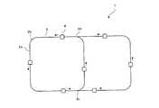
(搬送装置1の構成) 図1に示すように、搬送装置1は、被搬送物であるキャリア8を案内する搬送軌道2を備えている。搬送軌道2は、直線部2aとコーナー部2bと分岐部2cと合流部2dとを適宜組み合わせて構成される。搬送軌道2の周囲には、キャリア8を一時保管する図示しないストッカ等が配置されている。(Structure of the conveying apparatus 1) As shown in FIG. 1, the
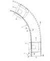
まず、図2を用いて搬送軌道2の直線部2aとコーナー部2bについて説明する。図2に示すように、搬送軌道2の直線部2aには、キャリア8を直線方向に案内する主軌道3が設けられているとともに、搬送軌道2のコーナー部2bには、キャリア8の進行方向を90°変更するコーナー軌道4が設けられている。なお、コーナー軌道4がキャリア8の進行方向を変更する角度は90°に限定されない。主軌道3は、図示しないフレームに所定の間隔で配設され、キャリア8を荷受け可能な複数の主軌道用ローラ対13を備えている。また、コーナー軌道4は、図示しないフレームに所定の間隔で配設され、キャリア8を荷受け可能な複数の右側ローラ14R及び複数の左側ローラ14Lを備えている。 First, the
主軌道用ローラ対13を構成するローラ13L,13Rの各々は、円筒状の荷受け部13aと、キャリア8が主軌道3上から逸脱しないよう左右方向の動きを強制的に規正するフランジ13bとを備えている。コーナー軌道4に設けられた各右側ローラ14R及び各左側ローラ14Lは、テーパ状の荷受け部14aと、キャリア8がコーナー軌道4上から逸脱しないよう左右方向の動きを強制的に規正するフランジ14bとを備えている。特に、コーナー軌道4上においてキャリア8には外周方向に向かう遠心力が作用するが、右側ローラ14Rのフランジ14bにより、この遠心力を抑制することが可能である。コーナー軌道4に設けられた右側ローラ14R及び左側ローラ14Lは、後述する分岐軌道6及び合流軌道7に設けられた右側ローラ及び左側ローラと同様の構成である。なお、主軌道用ローラ対13を構成するローラ13L,13Rのどちらか一方が駆動ローラであり、他方が従動ローラであってもよいし、両者が駆動ローラであってもよい。また、コーナー軌道4に設けられた右側ローラ14Rと左側ローラ14Lのどちらか一方が駆動ローラであり、他方が従動ローラであってもよいし、両者が駆動ローラであってもよい。また、右側ローラ14Rの個数と左側ローラ14Lの個数とは必ずしも同一でなく、通常は経路長の長い外周側の右側ローラ14Rの個数の方が、内周側の左側ローラ14Lの個数よりも若干多くされる。 Each of the
次に、図3乃至図7を用いて搬送軌道2の分岐部2cについて説明する。図3に示すように、搬送軌道2の分岐部2cには、主軌道3により案内されてきたキャリア8の進行方向を直線方向に維持する直線軌道5と、キャリア8の進行方向を90°変更する分岐軌道6とが、一部が重なり合うように設けられている。なお、分岐軌道6がキャリア8の進行方向を変更する角度は90°に限定されない。直線軌道5は、図示しないフレームに所定の間隔で配設され、キャリア8を荷受け可能な複数の直線軌道用ローラ対15を備えている。また、分岐軌道6は、図示しないフレームに所定の間隔で配設され、キャリア8を荷受け可能な複数の右側ローラ16R及び複数の左側ローラ16Lを備えている。 Next, the
直線軌道用ローラ対15を構成するローラ15L,15Rの各々は、円筒状の荷受け部15aと、キャリア8が直線軌道5上から逸脱しないよう左右方向の動きを強制的に規正するフランジ15bとを備えている。分岐軌道6に設けられた右側ローラ16R及び左側ローラ16Lは、コーナー軌道4に設けられた右側ローラ14R及び左側ローラ14Lと同様に構成され、テーパ状の荷受け部16aと、キャリア8が分岐軌道6上から逸脱しないよう左右方向の動きを強制的に規正するフランジ16bとを備えている。特に、分岐軌道6上においてキャリア8には外周方向に向かう遠心力が作用するが、右側ローラ16Rのフランジ16bにより、この遠心力を抑制することが可能である。なお、直線軌道用ローラ対15を構成するローラ15L,15Rのどちらか一方が駆動ローラであり、他方が従動ローラであってもよいし、両者が駆動ローラであってもよい。また、分岐軌道6に設けられた右側ローラ16Rと左側ローラ16Lのどちらか一方が駆動ローラであり、他方が従動ローラであってもよいし、両者が駆動ローラであってもよい。また、右側ローラ16Rの個数と左側ローラ16Lの個数とは必ずしも同一でなく、通常は経路長の長い外周側の右側ローラ16Rの個数の方が、内周側の左側ローラ16Lの個数よりも若干多くされる。 Each of the
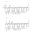
図4は、分岐部2cをキャリア8の底面から見た図である。図中、分岐部2cは破線で囲われた領域である。分岐部2cの直線軌道5の上流側(図中、下側)及び下流側(図中、上側)は直線部2aであって、主軌道3が設けられている。また、分岐部2cの分岐軌道6の下流側(図中、右側)も直線部2aであって、主軌道3が設けられている。直線軌道5の上流側の主軌道3の側方には第1センサ9aが設けられ、分岐部2cに進入するキャリア8の情報を取得するようになっている。本実施の形態において、キャリア8の情報とは、各キャリアが有する識別番号である。また、直線軌道5の下流側の主軌道3の側方であって、分岐部2cに近接する位置には、第2センサ9bが設けられ、分岐部2cの直線軌道5を通過したキャリア8を感知するようになっている。また、分岐軌道6の下流側の主軌道3の側方であって、分岐部2cに近接する位置には、第3センサ9cが設けられ、分岐部2cの分岐軌道6を通過したキャリア8を感知するようになっている。 FIG. 4 is a view of the
図4の2点鎖線で囲われた要部Aを拡大した図5に示すように、直線軌道5を構成するローラ15L,15Rと、分岐軌道6を構成するローラ16R,16Lとは、分岐が開始される地点Bにおいて交互に連設されている。直線軌道用ローラ対15を構成するローラ15L,15Rの直径は夫々L2に設定されている。一方、分岐軌道6を構成し、カーブの内周側となる左側ローラ16Lの直径はL2に、カーブの外周側となる右側ローラ16Rの直径はL1に設定されている。また、主軌道用ローラ対13を構成するローラ13L,13Rの直径は夫々L1に設定されている。例えば、分岐部2cの分岐軌道6の曲率半径が1mの場合、L1は30mm、L2は20mmである。なお、曲率半径及びL1,L2の値はこれに限定されるものではない。また、ローラ16L,16Rなどテーパ状の荷受け部を備えたローラにあっては、荷受け部の厚みdに対してd/2の位置の幅をローラの直径として定義している。ローラの直径には、フランジの幅は含まれない。 As shown in FIG. 5 in which the main part A surrounded by the two-dot chain line in FIG. 4 is enlarged, the
図5のC−C断面図である図6に示すように、分岐軌道6を構成するローラ16L,16Rの荷受け部16aは、水平面10に対して傾斜した軸16Aを中心とする円錐20の側面の一部をなしている。即ち、荷受け部16aはテーパ状である。そして、軸16Aを中心とする円錐20の垂直方向上端に位置する側面21が水平となるようにされている。これにより、ローラ16L,16Rの荷受け部16aに乗ったキャリア8は水平に維持される。ここで、分岐軌道6を構成するローラ16L,16Rの直径を図5のようにL1、L2に設定すると、上述したように、左側ローラ16Lの直径と右側ローラ16Rの直径とは異なっている(右側ローラ16Rの方が大きい)から、右側ローラ16Rと左側ローラ16Lとを回転させたときに、直径の大きな右側ローラ16Rの回転速度が直径の小さな左側ローラ16Lの回転速度よりも早くなる。よって、搬送距離の長い外周側におけるキャリア8の搬送速度を、搬送距離の短い内周側におけるキャリア8の搬送速度よりも早くするための特別な機構を用いなくても、直径の大きな右側ローラ16Rを外周側として、キャリア8をその進行方向を変えながらスムーズに搬送することができる。また、荷受け部16aをテーパ状にすることにより、荷受け部16aとキャリア8との間で滑りが生じ難いようにしているから、キャリア8とローラ16L,16Rとの滑りによる発塵を抑制することができる。 As shown in FIG. 6 which is a cross-sectional view taken along the line CC of FIG. Is part of. That is, the
一方、直線軌道5を構成する直線軌道用ローラ対15の荷受け部15aは、水平面10に対して平行(即ち、水平)な軸15Aを中心とする円筒30の側面の一部をなしている。即ち、荷受け部15aは円筒状である。 On the other hand, the
なお、コーナー軌道4を構成するローラ14L,14Rは、分岐軌道6を構成するローラ16L,16Rと同様のテーパ状の荷受け部14aと、フランジ14bとを備えている。これにより、キャリア8をその進行方向を変えながらスムーズに搬送することができるとともに、発塵が抑制されている。 The
また、図6において、第1センサ9a(図4参照)により分岐部2cに進入してくるキャリア8の情報を取得した図示しないシステムコントローラが、キャリア8の進行方向を90°変更する場合には、搬送装置1を構成する切替手段としての伸縮ポール40(図7参照)が伸長されて、分岐軌道6を構成するローラ16L,16Rの垂直方向の高さが、主軌道3を構成する図示しない主軌道用ローラ対13の垂直方向の高さD(基準高さDという)に位置されるとともに、切替手段としての伸縮ポール41(図7参照)が収縮されて、直線軌道5を構成するローラ15L,15Rの垂直方向の高さが、基準高さDよりも低い位置E(低位置Eという)に位置される。伸縮ポール40及び伸縮ポール41は、電動駆動方式により伸縮されるが、空圧駆動方式やギア駆動方式であってもよい。 Further, in FIG. 6, when a system controller (not shown) that has acquired information on the
一方、第1センサ9a(図4参照)により分岐部2cに進入してくるキャリア8の情報を取得した図示しないシステムコントローラが、キャリア8の進行方向を直線方向に維持する場合には、伸縮ポール40(図7参照)が収縮されて、分岐軌道6を構成するローラ16L,16Rの垂直方向の高さが低位置Eに位置されるとともに、伸縮ポール41(図7参照)が伸長されて、直線軌道5を構成するローラ15L,15Rの垂直方向の高さが基準高さDに位置される。 On the other hand, when a system controller (not shown) that has acquired information on the
具体的には、図7(a)、(b)に示すように、分岐軌道6の右側ローラ16Rが例えば5つ設けられたフレーム26と、直線軌道5の右側ローラ15Rが例えば5つ設けられたフレーム25とが、右側ローラ16Rと右側ローラ15Rとがキャリア8の進行方向に対して交互に位置するように設けられており、キャリア8の進行方向に応じて、フレーム26が伸縮ポール40により上下動されるとともに、フレーム25が伸縮ポール41により上下動される。 Specifically, as shown in FIGS. 7A and 7B, for example, a
即ち、分岐部2cに進入してくるキャリア8の進行方向が90°変更される場合には、図7(a)に示すように、伸縮ポール40の伸長によって、分岐軌道6の右側ローラ16Rの上端が基準高さDに位置するようにフレーム26が上方に位置されるとともに、伸縮ポール41の収縮によって、直線軌道5の右側ローラ15Rの上端がキャリア8に当接しない低位置Eに位置するようにフレーム25が下方に位置される。 That is, when the traveling direction of the
逆に、分岐部2cに進入してくるキャリア8の進行方向が直線方向に維持される場合には、図7(b)に示すように、伸縮ポール40の収縮によって、分岐軌道6の右側ローラ16Rの上端がキャリア8に当接しない低位置Eに位置するようにフレーム26が下方に位置されるとともに、伸縮ポール41の伸長によって、直線軌道5の右側ローラ15Rの上端が基準高さDに位置するようにフレーム25が上方に位置される。 On the contrary, when the traveling direction of the
フレーム26及びフレーム25が上下動する距離L3は、フランジ16b及びフランジ15bの高さを考慮して設定される。例えば、フランジ16b及びフランジ15bの高さが5mmであれば、フレーム26及びフレーム25が上下動する距離L3は5mmよりも大きく設定される。 The distance L3 in which the
分岐軌道6の左側ローラ16L及び直線軌道5の左側ローラ15Lについても、フレーム26、フレーム25と同様のフレームに設けられて、切替手段としての伸縮ポールにより上下動される。なお、切替手段は伸縮ポールに限定されるものではなく、フレームを上下動させるものであればなんでもよい。 The
このように、分岐部2cに設けられた伸縮ポール40,41が、キャリア8の進行方向に応じて、分岐軌道6と直線軌道5のどちらかでキャリア8を案内させるように分岐軌道6と直線軌道5とを切り替えるから、キャリア8を直線方向に案内する場合のみならず、キャリア8を進行方向が変わるように案内する場合であっても、分岐軌道6と直線軌道5とを切り替えるだけで、キャリア8を一時停止させることなく搬送することができる場合があるとともに、ターンテーブルのように原点復帰させる時間を必要としないため、キャリア8の向きを変えるのに必要な時間を短縮することができる。 As described above, the
また、伸縮ポール40,41は、分岐軌道6と直線軌道5のどちらか一方を基準高さDに位置させて主軌道3に連続させるとともに、他方を低位置Eに位置させてキャリア8から離間させることで、分岐軌道6と直線軌道5とを切り替えるから、切り替えに要する時間が短くて済む。 The
図4に戻って、破線で囲われた領域である分岐部2cを他のキャリア8が進行中の場合、即ち、第1センサ9aがキャリア8の情報を取得した後に、第2センサ9b或いは第3センサ9cがキャリア8を感知していない状態である場合、分岐部2cを他のキャリア8の進行方向と異なる方向に進行しようとするキャリア8は、他のキャリア8が分岐部2cを通過するまで、即ち、第2センサ9b或いは第3センサ9cがキャリア8を感知した後にフレーム26とフレーム25とが伸縮ポール40,41により上下動されるまで、分岐部2cの手前で一時停止される。具体的には、他のキャリア8が分岐軌道6を進行中であれば、直線軌道5を構成する直線軌道用ローラ対15(ローラ15L,15R)が低位置Eに位置しているため、直線軌道5を進行しようとするキャリア8は、第3センサ9cが他のキャリア8を感知し、フレーム25が基準高さDに位置されるとともに、フレーム26が低位置Eに位置されるまで、分岐部2cの手前で一時停止される。そして、他のキャリア8が分岐軌道6を通過したことを第3センサ9cが感知し、ローラ15L,15R(つまり、直線軌道5)が基準高さDに、ローラ16L,16R(つまり、分岐軌道6)が低位置Eにそれぞれ位置された後に、一時停止していたキャリア8が直線軌道5を進行することになる。 Returning to FIG. 4, when another
一方、破線で囲われた領域である分岐部2cを他のキャリア8が進行中の場合であっても、分岐部2cを他のキャリア8の進行方向と同じ方向に進行しようとするキャリア8は、分岐部2cの手前で一時停止されることなく進行される。これは、直線軌道5及び分岐軌道6の高さを変更する必要がないからである。 On the other hand, even when the
次に、図8を用いて搬送軌道2の合流部2dについて説明する。図8に示すように、合流部2dには、主軌道3により案内されてきたキャリア8の進行方向を直線方向に維持する直線軌道5と、キャリア8の進行方向を90°変更させて、キャリア8を主軌道3に合流するように案内する合流軌道7とが、一部が重なり合うように設けられている。なお、合流軌道7がキャリア8の進行方向を変更する角度は90°に限定されない。直線軌道5は、分岐部2cにおける直線軌道5と同様の構成であるため、その説明を省略する。合流軌道7は、図示しないフレームに所定の間隔で配設され、キャリア8を荷受け可能な複数の右側ローラ17R及び複数の左側ローラ17Lを備えている。 Next, the
合流軌道7を構成するローラ17L,17Rは、分岐軌道6を構成するローラ16L,16Rと同様の構成である。即ち、テーパ状の荷受け部17aと、キャリア8が合流軌道7上から逸脱しないよう左右方向の動きを強制的に規正するフランジ17bとを備えている。特に、合流軌道7上においてキャリア8には外周方向に向かう遠心力が作用するが、右側ローラ17Rのフランジ17bにより、この遠心力を抑制することが可能である。また、荷受け部17aをテーパ状にすることにより、荷受け部17aとキャリア8との間で滑りが生じ難いようにしているから、キャリア8とローラ17L,17Rとの滑りによる発塵を抑制することができる。これらローラ17L,17Rは、分岐軌道6を構成するローラ16L,16Rと同様に、図7に示したような、伸縮ポールによって上下動されるフレームに設けられている。なお、合流軌道7を構成するローラ17L,17Rのどちらか一方が駆動ローラであり、他方が従動ローラであってもよいし、両者が駆動ローラであってもよい。また、右側ローラ17Rの個数と左側ローラ17Lの個数とは必ずしも同一でなく、通常は経路長の長い外周側の右側ローラ17Rの個数の方が、内周側の左側ローラ17Lの個数よりも若干多くされる。 The
図9は、合流部2dをキャリア8の底面から見た図である。図中、合流部2dは破線で囲われた領域である。合流部2dの直線軌道5の上流側(図中、下側)及び下流側(図中、上側)は直線部2aであって、主軌道3が設けられている。また、合流部2dの合流軌道7の上流側(図中、右側)も直線部2aであって、主軌道3が設けられている。直線軌道5の上流側の主軌道3の側方には第4センサ19aが設けられ、合流部2dに進入するキャリア8の情報を取得するようになっている。また、直線軌道5の下流側の主軌道3の側方であって、合流部2dに近接する位置には、第5センサ19bが設けられ、合流部2dの直線軌道5を通過したキャリア8を感知するようになっている。また、合流軌道7の上流側の主軌道3の側方であって、合流部2dに近接する位置には、第6センサ19cが設けられ、合流部2dに進入するキャリア8の情報を取得するようになっている。 FIG. 9 is a view of the
図9に示すように、直線軌道5を構成するローラ15L,15Rと、合流軌道7を構成するローラ17L,17Rとは、合流が完了する地点Dにおいて交互に連設されている。直線軌道5を構成するローラ15L,15Rの直径は夫々L2に設定されている。一方、合流軌道7を構成し、カーブの内周側となる左側ローラ17Lの直径はL2に、カーブの外周側となる右側ローラ17Rの直径はL1に設定されている。例えば、分岐部2cの合流軌道7の曲率半径が1mの場合、L1は30mm、L2は20mmである。なお、曲率半径及びL1,L2の値はこれに限定されるものではない。 As shown in FIG. 9, the
また、図9において、図示しないシステムコントローラが、第6センサ19cにより合流部2dに進入してくるキャリア8の情報を取得した場合、合流軌道7の上流側に位置するキャリア8を合流部2dの下流側の主軌道3に合流させるために、図7に示したような図示しない伸縮ポールの伸長によって、合流軌道7のローラ17L,17Rが設けられたフレームが上方に位置されて、ローラ17L,17R(つまり、合流軌道7)の垂直方向の高さが基準高さDに位置されるとともに、図示しない他の伸縮ポールの収縮によって、直線軌道5のローラ15L,15Rが設けられたフレームが下方に位置されて、ローラ15L,15R(つまり、直線軌道5)の垂直方向の高さが低位置Eに位置される。 In FIG. 9, when a system controller (not shown) acquires information on the
一方、図示しないシステムコントローラが、第4センサ19aにより合流部2dに進入してくるキャリア8の情報を取得した場合、直線軌道5の上流側に位置するキャリア8を合流部2dの下流側の主軌道3に合流させるために、図示しない伸縮ポールの収縮によって、合流軌道7のローラ17L,17Rが設けられたフレームが下方に位置されて、合流軌道7の垂直方向の高さが低位置Eに位置されるとともに、図示しない他の伸縮ポールの伸長によって、直線軌道5のローラ15L,15Rが設けられたフレームが上方に位置されて、直線軌道5の垂直方向の高さが基準高さDに位置される。 On the other hand, when a system controller (not shown) acquires information on the
また、破線で囲われた領域である合流部2dを他のキャリア8が進行中の場合、即ち、システムコントローラが第4センサ19a或いは第6センサ19cからキャリア8の情報を取得した後に、第5センサ19bからのキャリア8の感知情報を取得していない場合、合流部2dを他のキャリア8の進行方向と異なる方向から進入しようとするキャリア8は、他のキャリア8が合流部2dを通過するまで、即ち、第5センサ9bが他のキャリア8を感知した後に合流軌道7と直線軌道5とが切り替えられるまで、合流部2dの手前で一時停止される。具体的には、他のキャリア8が合流軌道7を進行中であれば、直線軌道5を構成するローラ15L,15R(つまり、直線軌道用ローラ対15)が低位置Eに位置しているため、直線軌道5を進行しようとするキャリア8は、第5センサ19bが他のキャリア8を感知し、直線軌道5が基準高さDに位置されるとともに、合流軌道7が低位置Eに位置されるまで、合流部2dの手前で一時停止される。そして、他のキャリア8が合流軌道7を通過したことを第5センサ19bが感知し、直線軌道5が基準高さDに、合流軌道7が低位置Eにそれぞれ位置された後に、一時停止していたキャリア8が直線軌道5を進行することになる。また、他のキャリア8が直線軌道5を進行中であれば、合流軌道7を構成するローラ17L,17Rが低位置Eに位置しているため、合流軌道7を進行しようとするキャリア8は、第5センサ19bが他のキャリア8を感知し、合流軌道7が基準高さDに位置されるとともに、直線軌道5が低位置Eに位置されるまで、合流部2dの手前で一時停止される。そして、他のキャリア8が直線軌道5を通過したことを第5センサ19bが感知し、合流軌道7が基準高さDに、直線軌道5が低位置Eにそれぞれ位置された後に、一時停止していたキャリア8が合流軌道7を進行することになる。 Further, when another
一方、破線で囲われた領域である合流部2dを他のキャリア8が進行中の場合であっても、合流部2dを他のキャリア8の進行方向と同じ方向に進行しようとするキャリア8は、合流部2dの手前で一時停止されることなく進行される。これは、直線軌道5及び合流軌道7の高さを変更する必要がないからである。 On the other hand, even if the
また、異なる2つの進行方向から別々のキャリア8が同時に合流部2dに進入しようとしている場合、即ち、システムコントローラが第4センサ19a及び第6センサ19cから同時に別々のキャリア8の情報を取得した場合、システムコントローラは、どちらのキャリア8を優先して合流部2dに進入させるかを決定する。そして、優先されたキャリア8が合流部2dを進行中、優先されなかったキャリア8は、合流部2dの手前で一時停止されることとなる。 Further, when
このように、合流部2dに設けられた図示しない伸縮ポールが、キャリア8の合流部2dへの進入状況に応じて、合流軌道7と直線軌道5のどちらか一方でキャリア8を案内させるように合流軌道7と直線軌道5とを切り替えるから、キャリア8を主軌道3と同じ進行方向から主軌道3に合流するように案内する場合のみならず、キャリア8を主軌道3とは異なる進行方向から主軌道3に合流するように案内する場合であっても、合流軌道7と直線軌道5とを切り替えるだけで、キャリア8を一時停止させることなく搬送することができる場合があるとともに、ターンテーブルのように原点復帰させる時間を必要としないため、キャリア8の向きを変えるのに必要な時間を短縮することができる。 In this way, an unillustrated telescopic pole provided in the merging
また、図示しない伸縮ポールは、合流軌道7と直線軌道5のどちらか一方を基準高さDに位置させて主軌道3に連続させるとともに、他方を低位置Eに位置させてキャリア8から離間させることで、合流軌道7と直線軌道5とを切り替えるから、切り替えに要する時間が短くて済む。 Further, the telescopic pole (not shown) has one of the merging
(搬送装置1の動作)
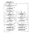
上記構成において、図10の分岐部軌道切替処理ルーチン及び図11の合流部軌道切替処理ルーチンを参照して、搬送装置1の動作について説明する。図10の分岐部軌道切替処理ルーチンは、分岐部2cにおいて、図11の合流部軌道切替処理ルーチンは、合流部2dにおいて、夫々独立して実行される。(Operation of transport device 1)
In the above configuration, the operation of the
まず、図10の分岐部軌道切替処理ルーチンについて説明する。分岐部軌道切替処理ルーチンが実行されると、まず、分岐部2cの上流側の主軌道3の側方に設けられた第1センサ9a(図4参照)がキャリア8をセンシングしたか否かが判定され(ステップS1)、第1センサ9aがキャリア8をセンシングしなければ(ステップS1,NO)、分岐部2cに進入するキャリア8がないとしてステップS1から再実行される。一方、第1センサ9aがキャリア8をセンシングすると(ステップS1,YES)、このキャリア8の情報がシステムコントローラにより取得される(ステップS2)。そして、このキャリア8を直進させるか否かがシステムコントローラにより判定され(ステップS3)、このキャリア8を直線軌道5により直進させるのであれば(ステップS3,YES)、分岐部2cに他のキャリア8が存在しているか否かが判定される(ステップS4)。 First, the branch part trajectory switching process routine of FIG. 10 will be described. When the branch section trajectory switching processing routine is executed, first, it is determined whether or not the
分岐部2cに他のキャリア8が存在していれば(ステップS4,YES)、他のキャリア8が直進中であるか否かが判定される(ステップS5)。他のキャリア8が直進中でなければ(ステップS5,NO)、他のキャリア8が分岐軌道6を進行中であると判断され、他のキャリア8が分岐軌道6を通過するまで、キャリア8が分岐部2cの手前で一時停止されて(ステップS6)、ステップS4から再実行される。一方、ステップS4において分岐部2cに他のキャリア8が存在していないか(ステップS4,NO)、ステップS5において他のキャリア8が直進中であれば(ステップS5,YES)、直線軌道5が基準高さDであるか否かが判定され(ステップS7)、直線軌道5が基準高さDであれば(ステップS7,YES)、軌道を切り替えることなくキャリア8は直線軌道5を進行し、ステップS1から再実行される。 If there is another
一方、直線軌道5が基準高さDでなければ(ステップS7,NO)、伸縮ポール41によって、直線軌道5が基準高さDに位置されるとともに(ステップS8)、伸縮ポール40によって、分岐軌道6が低位置Eに位置されて(ステップS9)、キャリア8は直線軌道5を進行し、ステップS1から再実行される。 On the other hand, if the
このように、キャリア8を直進させる場合、分岐部2cに設けられた伸縮ポール40,41が、キャリア8の進行方向(直進)に応じて、直線軌道5でキャリア8を案内させるように分岐軌道6と直線軌道5とを切り替えるから、分岐軌道6と直線軌道5とを切り替えるだけで、キャリア8を一時停止させることなく搬送することができる場合があるとともに、ターンテーブルのように原点復帰させる時間を必要としないため、キャリア8の向きを変えるのに必要な時間を短縮することができる。 In this way, when the
また、キャリア8を直進させる場合、伸縮ポール41が直線軌道5を基準高さDに位置させて主軌道3に連続させるとともに、伸縮ポール40が分岐軌道6を低位置Eに位置させてキャリア8から離間させることで、分岐軌道6と直線軌道5とを切り替えるから、切り替えに要する時間が短くて済む。 Further, when the
ステップS3において、キャリア8を直進させるのでなければ(ステップS3,NO)、キャリア8を分岐軌道6により進行させると判断されて、分岐部2cに他のキャリア8が存在しているか否かが判定される(ステップS10)。 In step S3, if the
分岐部2cに他のキャリア8が存在していれば(ステップS10,YES)、他のキャリア8が直進中であるか否かが判定される(ステップS11)。他のキャリア8が直進中であれば(ステップS11,YES)、他のキャリア8が直線軌道5を進行中であると判断され、他のキャリア8が直線軌道5を通過するまで、キャリア8が分岐部2cの手前で一時停止されて(ステップS12)、ステップS10から再実行される。一方、ステップS10において分岐部2cに他のキャリア8が存在していないか(ステップS10,NO)、ステップS11において他のキャリア8が直進中でなければ(ステップS11,NO)、分岐軌道6が基準高さDであるか否かが判定され(ステップS13)、分岐軌道6が基準高さDであれば(ステップS13,YES)、軌道を切り替えることなくキャリア8は分岐軌道6を進行し、ステップS1から再実行される。 If there is another
一方、分岐軌道6が基準高さDでなければ(ステップS13,NO)、伸縮ポール40によって、分岐軌道6が基準高さDに位置されるとともに(ステップS14)、伸縮ポール41によって、直線軌道5が低位置Eに位置されて(ステップS15)、キャリア8は分岐軌道6を進行し、ステップS1から再実行される。 On the other hand, if the
このように、キャリア8をカーブさせる場合、分岐部2cに設けられた伸縮ポール40,41が、キャリア8の進行方向(カーブ)に応じて、分岐軌道6でキャリア8を案内させるように分岐軌道6と直線軌道5とを切り替えるから、キャリア8を直線方向に案内する場合のみならず、キャリア8を進行方向が変わるように案内する場合であっても、分岐軌道6と直線軌道5とを切り替えるだけで、キャリア8を一時停止させることなく搬送することができる場合があるとともに、ターンテーブルのように原点復帰させる時間を必要としないため、キャリア8の向きを変えるのに必要な時間を短縮することができる。 In this way, when the
また、キャリア8をカーブさせる場合、伸縮ポール40が分岐軌道6を基準高さDに位置させて主軌道3に連続させるとともに、伸縮ポール41が直線軌道5を低位置Eに位置させてキャリア8から離間させることで、分岐軌道6と直線軌道5とを切り替えるから、切り替えに要する時間が短くて済む。 Also, when the
ここで、分岐軌道6を構成する左側ローラ16Lの直径と右側ローラ16Rの直径とは異なっている(右側ローラ16Rの方が大きい)から、ローラ16L,16Rを回転させたときに、直径の大きな右側ローラ16Rの回転速度が直径の小さな左側ローラ16Lの回転速度よりも早くなる。よって、搬送距離の長い外周側におけるキャリア8の搬送速度を、搬送距離の短い内周側におけるキャリア8の搬送速度よりも早くするための特別な機構を用いなくても、直径の大きな右側ローラ16Rを外周側として、キャリア8をその進行方向を変えながらスムーズに搬送することができる。また、左側ローラ16L及び右側ローラ16Rの荷受け部16aをテーパ状にすることにより、キャリア8とローラ16L,16Rとの滑りによる発塵を抑制している。 Here, since the diameter of the
更に、右側ローラ16Rにフランジ16bが設けられているため、分岐軌道6上においてキャリア8に作用する遠心力を、このフランジ16bにより抑制することが可能である。 Further, since the
次に、図11の合流部軌道切替処理ルーチンについて説明する。合流部軌道切替処理ルーチンが実行されると、まず、合流部2dの直線軌道5の上流側の主軌道3の側方に設けられた第4センサ19a(図9参照)がキャリア8をセンシングしたか否かが判定され(ステップS21)、第4センサ19aがキャリア8をセンシングすると(ステップS21,YES)、このキャリア8の情報がシステムコントローラにより取得される(ステップS22)。続いて、合流軌道7の上流側の主軌道3の側方であって、合流部2dに近接する位置に設けられた第6センサ19c(図9参照)がキャリア8をセンシングしたか否かが判定され(ステップS23)、第6センサ19cがキャリア8をセンシングすると(ステップS23,YES)、このキャリア8の情報がシステムコントローラにより取得される(ステップS24)。 Next, the merging portion trajectory switching processing routine of FIG. 11 will be described. When the merge section trajectory switching processing routine is executed, first, the
そして、第4センサ19aがセンシングしたキャリア8と、第6センサ19cがセンシングしたキャリア8のどちらを優先して合流部2dに進入させるかがシステムコントローラにより決定され(ステップS25)、直線軌道5を直進するキャリア8が先行されるのか否かが判定される(ステップS26)。直線軌道5を直進するキャリア8が先行されるのであれば(ステップS26,YES)、合流軌道7の手前に位置するキャリア8が一時停止される(ステップS27)。そして、合流部2dに他のキャリア8が存在しているか否かが判定される(ステップS28)。 Then, the system controller determines which of the
合流部2dに他のキャリア8が存在していれば(ステップS28,YES)、他のキャリア8が直進中であるか否かが判定される(ステップS29)。他のキャリア8が直進中でなければ(ステップS29,NO)、他のキャリア8が合流軌道7を進行中であると判断され、他のキャリア8が合流軌道7を通過するまで、キャリア8が合流部2dの手前で一時停止されて(ステップS30)、ステップS28から再実行される。一方、ステップS28において合流部2dに他のキャリア8が存在していないか(ステップS28,NO)、ステップS29において他のキャリア8が直進中であれば(ステップS29,YES)、直線軌道5が基準高さDであるか否かが判定され(ステップS31)、直線軌道5が基準高さDであれば(ステップS31,YES)、軌道を切り替えることなくキャリア8は直線軌道5を進行し、ステップS1から再実行される。 If there is another
一方、直線軌道5が基準高さDでなければ(ステップS31,NO)、伸縮ポールによって、直線軌道5が基準高さDに位置されるとともに(ステップS32)、他の伸縮ポールによって、合流軌道7が低位置Eに位置されて(ステップS33)、キャリア8は直線軌道5を進行し、ステップS1から再実行される。 On the other hand, if the
このように、キャリア8の合流部2dへの進入状況に応じて、直線軌道5にキャリア8を進入させる場合、合流部2dに設けられた伸縮ポールが、直線軌道5でキャリア8を案内させるように合流軌道7と直線軌道5とを切り替えるから、合流軌道7と直線軌道5とを切り替えるだけで、キャリア8を一時停止させることなく搬送することができる場合があるとともに、ターンテーブルのように原点復帰させる時間を必要としないため、キャリア8の向きを変えるのに必要な時間を短縮することができる。 As described above, when the
また、直線軌道5を直進するキャリア8を先行させる場合、図示しない伸縮ポールが直線軌道5を基準高さDに位置させて主軌道3に連続させるとともに、図示しない他の伸縮ポールが合流軌道7を低位置Eに位置させてキャリア8から離間させることで、合流軌道7と直線軌道5とを切り替えるから、切り替えに要する時間が短くて済む。 Further, when the
一方、ステップS26において、直線軌道5を直進するキャリア8が先行されないのであれば(ステップS26,NO)、直線軌道5の手前に位置するキャリア8が一時停止され(ステップS36)、ステップS37に進む。 On the other hand, in step S26, if the
さらに、ステップS21において、第4センサ19aがキャリア8をセンシングしなければ(ステップS21,NO)、続いて、第6センサ19cがキャリア8をセンシングしたか否かが判定され(ステップS34)、第6センサ19cがキャリア8をセンシングしなければ(ステップS34,NO)、ステップS21から再実行される。一方、第6センサ19cがキャリア8をセンシングすると(ステップS34,YES)、このキャリア8の情報がシステムコントローラにより取得され(ステップS35)、ステップS37に進む。 In step S21, if the
ステップS35の後、又はステップS36の後に、合流部2dに他のキャリア8が存在しているか否かが判定され(ステップS37)、合流部2dに他のキャリア8が存在していれば(ステップS37,YES)、他のキャリア8が直進中であるか否かが判定される(ステップS38)。他のキャリア8が直進中であれば(ステップS38,YES)、他のキャリア8が直線軌道5を進行中であると判断され、他のキャリア8が直線軌道5を通過するまで、キャリア8が合流部2dの手前で一時停止されて(ステップS39)、ステップS37から再実行される。 After step S35 or after step S36, it is determined whether or not another
一方、ステップS37において合流部2dに他のキャリア8が存在していないか(ステップS37,NO)、ステップS38において他のキャリア8が直進中でなければ(ステップS38,NO)、合流軌道7が基準高さDであるか否かが判定され(ステップS40)、合流軌道7が基準高さDであれば(ステップS40,YES)、軌道を切り替えることなくキャリア8は合流軌道7を進行し、ステップS1から再実行される。一方、合流軌道7が基準高さDでなければ(ステップS40,NO)、図示しない伸縮ポールによって、合流軌道7が基準高さDに位置されるとともに(ステップS41)、図示しない他の伸縮ポールによって、直線軌道5が低位置Eに位置されて(ステップS42)、キャリア8は合流軌道7を進行し、ステップS1から再実行される。 On the other hand, if there is no
このように、キャリア8の合流部2dへの進入状況に応じて、合流軌道7にキャリア8を進入させる場合、合流部2dに設けられた図示しない伸縮ポールが、合流軌道7でキャリア8を案内させるように合流軌道7と直線軌道5とを切り替えるから、合流軌道7と直線軌道5とを切り替えるだけで、キャリア8を一時停止させることなく搬送することができる場合があるとともに、ターンテーブルのように原点復帰させる時間を必要としないため、キャリア8の向きを変えるのに必要な時間を短縮することができる。 As described above, when the
また、合流軌道7を曲進するキャリア8を先行させる場合、図示しない伸縮ポールが合流軌道7を基準高さDに位置させて主軌道3に連続させるとともに、図示しない他の伸縮ポールが直線軌道5を低位置Eに位置させてキャリア8から離間させることで、合流軌道7と直線軌道5とを切り替えるから、切り替えに要する時間が短くて済む。 In addition, when the
ここで、合流軌道7を構成する左側ローラ17Lの直径と右側ローラ17Rの直径とは異なっている(右側ローラ17Rの方が大きい)から、ローラ17L,17Rを回転させたときに、直径の大きな右側ローラ17Rの回転速度が直径の小さな左側ローラ17Lの回転速度よりも早くなる。よって、搬送距離の長い外周側におけるキャリア8の搬送速度を、搬送距離の短い内周側におけるキャリア8の搬送速度よりも早くするための特別な機構を用いなくても、直径の大きな右側ローラ17Rを外周側として、キャリア8をその進行方向を変えながらスムーズに搬送することができる。また、左側ローラ17L及び右側ローラ17Rの荷受け部17aをテーパ状にすることにより、キャリア8とローラ17L,17Rとの滑りによる発塵を抑制している。 Here, since the diameter of the
更に、右側ローラ17Rにフランジ17bが設けられているため、合流軌道7上においてキャリア8に作用する遠心力を、このフランジ17bにより抑制することが可能である。 Furthermore, since the
(本実施の形態の概要)
以上のように、本実施の形態の搬送装置1は、キャリア8を搬送する搬送装置1であって、キャリア8を直線方向に案内する主軌道3を備えた直線部2aと、キャリア8を進行方向が変わるように案内する分岐軌道6とキャリア8を直線方向に案内する直線軌道5とを備えた分岐部2cとを有する搬送軌道2と、分岐部2cに設けられ、キャリア8の進行方向に応じて、分岐軌道6と直線軌道5のどちらか一方でキャリア8を案内させるように分岐軌道6と直線軌道5とを切り替える伸縮ポール40,41と、を有する構成にされている。(Outline of this embodiment)
As described above, the
上記の構成によれば、分岐部2cに設けられた伸縮ポール40,41が、キャリア8の進行方向に応じて、分岐軌道6と直線軌道5のどちらかでキャリア8を案内させるように分岐軌道6と直線軌道5とを切り替えるから、キャリア8を直線方向に案内する場合のみならず、キャリア8を進行方向が変わるように案内する場合であっても、分岐軌道6と直線軌道5とを切り替えるだけで、キャリア8を一時停止させることなく搬送することができる場合があるとともに、ターンテーブルのように原点復帰させる時間を必要としないため、キャリア8の向きを変えるのに必要な時間を短縮することができる。 According to the above configuration, the
また、本実施の形態の搬送装置1において、伸縮ポール40,41は、分岐軌道6と直線軌道5のどちらか一方を主軌道3に連続させるとともに、他方をキャリア8から離間させることで、分岐軌道6と直線軌道5とを切り替える構成にされている。上記の構成によれば、伸縮ポール40,41は、分岐軌道6と直線軌道5のどちらか一方を主軌道3に連続させるとともに、他方をキャリア8から離間させることで、分岐軌道6と直線軌道5とを切り替えるから、切り替えに要する時間が短くて済む。 Further, in the
また、本実施の形態の搬送装置1において、分岐軌道6は、キャリア8を荷受け可能でそれぞれ所定の間隔で配設された複数の右側ローラ16R及び複数の左側ローラ16Lで構成されており、各右側ローラ16R及び各左側ローラ16Lは、キャリア8の搬送面に対して傾斜した軸16Aを中心とする円錐20の側面の一部を荷受け部16aとし、右側ローラ16Rと左側ローラ16Lとで直径が異なっている構成にされている。上記の構成によれば、右側ローラ16Rと左側ローラ16Lとで直径が異なっており、右側ローラ16Rと左側ローラ16Lとを回転させたときに、直径の大きな右側ローラ16Rの回転速度が直径の小さな左側ローラ16Lの回転速度よりも早くなるから、キャリア8の外周側の搬送速度をキャリア8の内周側の搬送速度よりも早くするための特別な機構を用いなくても、直径の大きな右側ローラ16Rを外周側として、キャリア8をその進行方向を変えながらスムーズに搬送することができる。また、分岐軌道6の各右側ローラ16R及び各左側ローラ16Lは、円錐20の側面の一部からなるテーパ状の荷受け部16aを備えているため、キャリア8との滑りによる発塵を最小限に抑えることができる。 Further, in the
また、本実施の形態の搬送装置1は、キャリア8を搬送する搬送装置1であって、キャリア8を直線方向に案内する主軌道3を備えた直線部2aと、キャリア8を主軌道3とは異なる進行方向から主軌道3に合流するように案内する合流軌道7とキャリア8を主軌道3と同じ進行方向から主軌道3に合流するように案内する直線軌道5とを備えた合流部2dとを有する搬送軌道2と、合流部2dに設けられ、キャリア8の合流部2dへの進入状況に応じて、合流軌道7と直線軌道5のどちらか一方でキャリア8を案内させるように合流軌道7と直線軌道5とを切り替える伸縮ポールと、を有する構成にされている。 Further, the
上記の構成によれば、合流部2dに設けられた図示しない伸縮ポールが、キャリア8の合流部2dへの進入状況に応じて、合流軌道7と直線軌道5のどちらか一方でキャリア8を案内させるように合流軌道7と直線軌道5とを切り替えるから、キャリア8を主軌道3と同じ進行方向から主軌道3に合流するように案内する場合のみならず、キャリア8を主軌道3とは異なる進行方向から主軌道3に合流するように案内する場合であっても、合流軌道7と直線軌道5とを切り替えるだけで、キャリア8を一時停止させることなく搬送することができる場合があるとともに、ターンテーブルのように原点復帰させる時間を必要としないため、キャリア8の向きを変えるのに必要な時間を短縮することができる。 According to the above configuration, the telescopic pole (not shown) provided in the merging
また、本実施の形態の搬送装置1において、伸縮ポールは、合流軌道7と直線軌道5のどちらか一方を主軌道3に連続させるとともに、他方をキャリア8から離間させることで、合流軌道7と直線軌道5とを切り替える構成にされている。上記の構成によれば、伸縮ポールは、合流軌道7と直線軌道5のどちらか一方を主軌道3に連続させるとともに、他方をキャリア8から離間させることで、合流軌道7と直線軌道5とを切り替えるから、切り替えに要する時間が短くて済む。 Further, in the
また、本実施の形態の搬送装置1において、合流軌道7は、キャリア8を荷受け可能でそれぞれ所定の間隔で配設された複数の右側ローラ17R及び複数の左側ローラ17Lで構成されており、各右側ローラ17R及び各左側ローラ17Lは、キャリア8の搬送面に対して傾斜した軸を中心とする円錐の側面の一部を荷受け部17aとし、右側ローラ17Rと左側ローラ17Lとで直径が異なっている構成にされている。上記の構成によれば、右側ローラ17Rと左側ローラ17Lとで直径が異なっており、右側ローラ17Rと左側ローラ17Lとを回転させたときに、直径の大きな右側ローラ17Rの回転速度が直径の小さな左側ローラ17Lの回転速度よりも早くなるから、キャリア8の外周側の搬送速度をキャリア8の内周側の搬送速度よりも早くするための特別な機構を用いなくても、直径の大きな右側ローラ17Rを外周側として、キャリア8をその進行方向を変えながらスムーズに搬送することができる。また、合流軌道7の各右側ローラ17R及び各左側ローラ17Lは、円錐の側面の一部からなるテーパ状の荷受け部17aを備えているため、キャリア8との滑りによる発塵を最小限に抑えることができる。 Further, in the
また、本実施の形態の搬送装置1において、右側ローラ16R,17Rと左側ローラ16L,17Lのうち少なくとも外周側の右側ローラ16R,17Rは、外周側にフランジ16b,17bを備えている構成にされている。上記の構成によれば、外周側の右側ローラ16R,17Rは、外周側にフランジ16b,17bを備えているから、キャリア8が進行方向を変えながら進行する際にキャリア8に生じる遠心力をフランジ16b,17bにより抑制することができる。 Further, in the
(本発明の実施の形態の変形例)
また、本発明を好適な実施の形態に基づいて説明したが、本発明はその趣旨を超えない範囲において変更が可能である。即ち、図6において、円錐20の垂直方向上端に位置する側面21が、分岐軌道6を構成する右側ローラ16R側を高くして斜めになるように、円錐20の軸16Aが、例えば水平になっていてもよい。このようにすることで、右側ローラ16Rのフランジ16bにより、キャリア8に生じる遠心力を更に好適に抑制することができる場合がある。合流軌道7を構成する右側ローラ17Rについても同様である。(Modification of the embodiment of the present invention)
Moreover, although this invention was demonstrated based on suitable embodiment, this invention can be changed in the range which does not exceed the meaning. That is, in FIG. 6, the shaft 16 </ b> A of the
1 搬送装置
2 搬送軌道
2a 直線部
2c 分岐部
2d 合流部
3 主軌道
5 直線軌道
6 分岐軌道
7 合流軌道
8 キャリア
40,41 伸縮ポールDESCRIPTION OF
Claims (6)
Translated fromJapanese前記被搬送物を直線方向に案内する主軌道を備えた直線部と、前記被搬送物を進行方向が変わるように案内する分岐軌道と前記被搬送物を直線方向に案内する直線軌道とを備えた分岐部とを有し、前記直線軌道は、前記被搬送物を荷受け可能な複数の右側ローラ及び複数の左側ローラが所定の間隔で配設されて構成され、前記分岐軌道は、前記被搬送物を荷受け可能な複数の右側ローラ及び複数の左側ローラが所定の間隔で配設されて構成される搬送軌道と、
前記直線軌道の上流側の前記主軌道の側方に設けられ、前記分岐部に進入する前記被搬送物の情報を取得する第1センサと、
前記直線軌道の下流側の前記主軌道の側方に設けられ、前記分岐部の前記直線軌道を通過した前記被搬送物を感知する第2センサと、
前記分岐軌道の下流側の前記主軌道の側方に設けられ、前記分岐部の前記分岐軌道を通過した前記被搬送物を感知する第3センサと、
前記分岐部に設けられ、前記第1センサで取得した前記被搬送物の情報に基づき、前記被搬送物の進行方向に応じて、前記分岐軌道を構成する前記右側ローラ及び前記左側ローラと、前記直線軌道を構成する前記右側ローラ及び前記左側ローラとを上下動させ、前記分岐軌道と前記直線軌道のどちらか一方を前記主軌道に連続させるとともに、他方を前記被搬送物から離間させることで、前記分岐軌道と前記直線軌道とを切り替えて、前記分岐軌道と前記直線軌道のどちらか一方で前記被搬送物を案内させるように前記分岐軌道と前記直線軌道とを切り替える切替手段と、
を有し、先後の前記被搬送物が前記分岐軌道と前記直線軌道との間で異なる方向に進行しようとする場合は、前記第2センサまたは前記第3センサが先行する前記被搬送物を感知し、且つ、前記切替手段による切り替えが終了するまで、後ろの前記被搬送物を前記分岐部の手前で一時停止させ、先後の前記被搬送物が前記分岐軌道と前記直線軌道との間で同じ方向に進行しようとする場合は、後ろの前記被搬送物を前記分岐部の手前で一時停止させることなく進行させることを特徴とする搬送装置。A conveying device for conveying an object to be conveyed,
A linear portion having a main track for guiding the object to be conveyed in a linear direction; a branching track for guiding the object to be conveyed so that a traveling direction thereof changes; and a linear track for guiding the object to be conveyed in a linear direction.possess a branchedportion, said linear track, the plurality of right rollers and a plurality of left rollers capable consignment transported object is constructed is disposed at a predetermined interval, the branch track, the object to be transported a conveyor trackfor objects capable load receiving a plurality of right roller and a plurality of left rollers Ruconfigured are disposed at a predetermined interval,
A first sensor provided on a side of the main track on the upstream side of the straight track and acquiring information of the conveyed object entering the branch portion;
A second sensor that is provided on a side of the main track on the downstream side of the straight track, and that senses the object to be transported that has passed through the straight track of the branch portion;
A third sensor that is provided on a side of the main track on the downstream side of the branch track and senses the object to be conveyed that has passed through the branch track of the branch portion;
Theright roller and the left roller constituting the branch track according to the traveling direction of the transported object, based on the transported object information provided bythe first sensor, provided in the branching unit,By moving up and down the right roller and the left roller constituting a straight track, and continuing either one of the branch track and the straight track to the main track, and separating the other from the conveyed object, by switching between the branch track and the linear track, and switching means for switching the said branch track the so as to guide the object to be conveyed in either one of the branch track and the linear track and the linear track,
Have a, when the transported object after previous attempts to travel in different directions between the branch track and the linear track, sensing the transported object, wherein the second sensor or the third sensor precedes In addition, until the switching by the switching means is completed, the rear object to be transported is temporarily stopped before the branching unit, and the preceding and following objects are the same between the branching track and the straight track. If to be traveling in the direction, conveying apparatus according to claim Rukotoproceeded without pause behind the object to be conveyed in front of the branch portion.
前記分岐軌道を構成する前記右側ローラ及び前記左側ローラの各ローラは、前記被搬送物の搬送面に対して傾斜した軸または水平な軸を中心とする円錐の側面の一部を荷受け部とし、前記右側ローラと前記左側ローラとで直径が異なり、外周側の前記右側ローラまたは前記左側ローラの直径が大きくなるよう設定され、前記右側ローラと前記左側ローラのうち少なくとも外周側のローラは、外周側にフランジを備えることを特徴とする請求項1又は2に記載の搬送装置。At the point where the branching of the branching portion is started, the right roller and the left roller constituting the linear track and the right roller and the left roller constituting the branch track are alternately arranged ,
Each roller of theright roller and the left roller constituting the branching track has a part of a side surface of a cone centered on an axis inclinedor a horizontal axis with respect to the conveyance surface of the object to be conveyed as a load receiving portion, the right roller andRi said Do different diameter between the left rolleris set so that the diameter of the right roller or the left roller on the outer peripheral side is increased, at least the outer peripheral side of the roller of the right roller and the left roller periphery conveying apparatus according to claim 1 or 2, characterized in Rukotoa flange on the side.
前記被搬送物を直線方向に案内する主軌道を備えた直線部と、前記被搬送物を前記主軌道とは異なる進行方向から前記主軌道に合流するように案内する合流軌道と前記被搬送物を前記主軌道と同じ進行方向から前記主軌道に合流するように案内する直線軌道とを備えた合流部とを有し、前記直線軌道は、前記被搬送物を荷受け可能な複数の右側ローラ及び複数の左側ローラが所定の間隔で配設されて構成され、前記合流軌道は、前記被搬送物を荷受け可能な複数の右側ローラ及び複数の左側ローラが所定の間隔で配設されて構成される搬送軌道と、
前記直線軌道の上流側の前記主軌道の側方に設けられ、前記合流部に進入する前記被搬送物の情報を取得する第4センサと、
前記直線軌道の下流側の前記主軌道の側方に設けられ、前記合流部の前記直線軌道を通過した前記被搬送物を感知する第5センサと、
前記合流軌道の上流側の前記主軌道の側方に設けられ、前記合流部に進入する前記被搬送物の情報を取得する第6センサと、
前記合流部に設けられ、前記第4センサ及び前記第6センサで取得した前記被搬送物の情報に基づき、前記被搬送物の前記合流部への進入状況に応じて、前記合流軌道を構成する前記右側ローラ及び前記左側ローラと、前記直線軌道を構成する前記右側ローラ及び前記左側ローラとを上下動させ、前記合流軌道と前記直線軌道のどちらか一方を前記主軌道に連続させるとともに、他方を前記被搬送物から離間させることで、前記合流軌道と前記直線軌道とを切り替えて、前記合流軌道と前記直線軌道のどちらか一方で前記被搬送物を案内させるように前記合流軌道と前記直線軌道とを切り替える切替手段と、
を有し、先後の前記被搬送物が前記合流軌道と前記直線軌道との間で異なる方向から進入しようとする場合は、前記第5センサが先行する前記被搬送物を感知し、且つ、前記切替手段による切り替えが終了するまで、後ろの前記被搬送物を前記合流部の手前で一時停止させ、先後の前記被搬送物が前記合流軌道と前記直線軌道との間で同じ方向に進行しようとする場合は、後ろの前記被搬送物を前記合流部の手前で一時停止させることなく進行させることを特徴とする搬送装置。A conveying device for conveying an object to be conveyed,
A straight section having a main track for guiding the object to be conveyed in a linear direction, a merged track for guiding the object to be conveyed from a traveling direction different from the main track to the main track, and the object to be conveyedwas closed and a merging portion that includes a linear track for guiding to merge into the main track from the same traveling direction as the maintrack, the straight line trajectory, a plurality of right roller and capable load receiving the transported object a plurality of left rollers are configured are disposed at a predetermined interval, the merging track, said plurality of possible load receiving transferred object right rollers and a plurality of left rollers Ruconfigured are disposed at a predetermined interval A transport track;
A fourth sensor provided on a side of the main track on the upstream side of the straight track, and acquiring information of the object to be conveyed entering the junction;
A fifth sensor that is provided on a side of the main track on the downstream side of the linear track and senses the object to be transported that has passed through the linear track of the merging portion;
A sixth sensor that is provided on a side of the main track on the upstream side of the merging track and that acquires information on the conveyed object entering the merging portion;
Based on the information of the conveyed object provided in the merging part andacquired by the fourth sensor and the sixth sensor, themerging trajectory is configured according to the state of entry of the conveyed object into the merging part.The right roller and the left roller, and the right roller and the left roller constituting the linear track are moved up and down, and one of the merging track and the linear track is continued to the main track, and the other is The merged track and the linear track are switched so that the merged track and the linear track are switched, and the transported object is guided in one of the merged track and the linear track by being separated from the transported object. Switching means for switching between, and
Havea, when the transported object after previous attempts to enter from a different direction between the merging track and the linear track senses the transported object, wherein the fifth sensor is preceded, and the Until the switching by the switching unit is completed, the rear object to be transported is temporarily stopped before the joining part, and the preceding and following objects are about to travel in the same direction between the joining track and the linear track. to case, conveying device according to claim Rukotoproceeded without pause behind the object to be conveyed in front of the joint portion.
前記合流軌道を構成する前記右側ローラ及び前記左側ローラの各ローラは、前記被搬送物の搬送面に対して傾斜した軸または水平な軸を中心とする円錐の側面の一部を荷受け部とし、前記右側ローラと前記左側ローラとで直径が異なり、外周側の前記右側ローラまたは前記左側ローラの直径が大きくなるよう設定され、前記右側ローラと前記左側ローラのうち少なくとも外周側のローラは、外周側にフランジを備えることを特徴とする請求項4又は5に記載の搬送装置。
At the point where merging of the merging portion is started, the right roller and the left roller constituting the linear track and the right roller and the left roller constituting the merging track are alternately arranged ,
Each roller of theright roller and the left roller constituting the merging track has a part of a side surface of a cone centering on an axis inclinedor a horizontal axis with respect to a conveyance surface of the object to be conveyed, as a load receiving portion. the right roller andRi said Do different diameter between the left rolleris set so that the diameter of the right roller or the left roller on the outer peripheral side is increased, at least the outer peripheral side of the roller of the right roller and the left roller periphery conveying apparatus according to claim 4 or 5, characterized in Rukotoa flange on the side.
Priority Applications (5)
| Application Number | Priority Date | Filing Date | Title |
|---|---|---|---|
| JP2006043573AJP5168794B2 (en) | 2006-02-21 | 2006-02-21 | Transport device |
| TW096106193ATW200736138A (en) | 2006-02-21 | 2007-02-16 | Transport apparatus |
| US11/708,065US20070193859A1 (en) | 2006-02-21 | 2007-02-20 | Transport apparatus |
| KR1020070017600AKR20070083435A (en) | 2006-02-21 | 2007-02-21 | Conveying device |
| CNA2007100031692ACN101024450A (en) | 2006-02-21 | 2007-02-25 | Transport apparatus |
Applications Claiming Priority (1)
| Application Number | Priority Date | Filing Date | Title |
|---|---|---|---|
| JP2006043573AJP5168794B2 (en) | 2006-02-21 | 2006-02-21 | Transport device |
Publications (2)
| Publication Number | Publication Date |
|---|---|
| JP2007223683A JP2007223683A (en) | 2007-09-06 |
| JP5168794B2true JP5168794B2 (en) | 2013-03-27 |
Family
ID=38427046
Family Applications (1)
| Application Number | Title | Priority Date | Filing Date |
|---|---|---|---|
| JP2006043573AExpired - Fee RelatedJP5168794B2 (en) | 2006-02-21 | 2006-02-21 | Transport device |
Country Status (5)
| Country | Link |
|---|---|
| US (1) | US20070193859A1 (en) |
| JP (1) | JP5168794B2 (en) |
| KR (1) | KR20070083435A (en) |
| CN (1) | CN101024450A (en) |
| TW (1) | TW200736138A (en) |
Cited By (1)
| Publication number | Priority date | Publication date | Assignee | Title |
|---|---|---|---|---|
| EP3868690A1 (en) | 2020-02-19 | 2021-08-25 | Daifuku Co., Ltd. | Conveyor |
Families Citing this family (32)
| Publication number | Priority date | Publication date | Assignee | Title |
|---|---|---|---|---|
| JP2007217078A (en)* | 2006-02-14 | 2007-08-30 | Asyst Shinko Inc | Direction changing device |
| JP2010126334A (en)* | 2008-11-28 | 2010-06-10 | Ihi Corp | Branching device |
| CN103675303B (en) | 2010-07-23 | 2016-02-03 | 贝克曼考尔特公司 | Sensing system |
| JP5733569B2 (en)* | 2011-04-12 | 2015-06-10 | 株式会社ダイフク | Conveyor and equipment |
| JP6014123B2 (en) | 2011-05-13 | 2016-10-25 | ベックマン コールター, インコーポレイテッド | Laboratory product transport elements and pathway arrays |
| EP2707726B1 (en) | 2011-05-13 | 2018-07-18 | Beckman Coulter, Inc. | System and method including laboratory product transport element |
| BR112014011043A2 (en) | 2011-11-07 | 2017-06-13 | Beckman Coulter Inc | specimen container detection |
| CN104105969B (en) | 2011-11-07 | 2016-10-12 | 贝克曼考尔特公司 | Centrifuge system and workflow |
| WO2013070754A1 (en) | 2011-11-07 | 2013-05-16 | Beckman Coulter, Inc. | Robotic arm |
| CN104040357B (en)* | 2011-11-07 | 2016-11-23 | 贝克曼考尔特公司 | Halver system and workflow |
| KR20140091032A (en) | 2011-11-07 | 2014-07-18 | 베크만 컬터, 인코포레이티드 | Magnetic damping for specimen transport system |
| BR112014010955A2 (en) | 2011-11-07 | 2017-06-06 | Beckman Coulter Inc | system and method for processing samples |
| WO2014006707A1 (en) | 2012-07-04 | 2014-01-09 | 株式会社ダイフク | Transport conveyor and transport facility |
| CN102774641A (en)* | 2012-07-11 | 2012-11-14 | 无锡市福曼科技有限公司 | Shunting and merging mechanism of suspended sliding system |
| JP5861008B2 (en) | 2012-09-14 | 2016-02-16 | ベックマン コールター, インコーポレイテッド | Analysis system with capillary transporter |
| CN103129930A (en)* | 2013-02-16 | 2013-06-05 | 上海三禾服装物流设备制造有限公司 | Manual line translation branch system |
| CN103332427B (en)* | 2013-05-21 | 2016-03-02 | 中银(宁波)电池有限公司 | A kind of Battery replenishment device |
| CN106586504A (en)* | 2015-10-14 | 2017-04-26 | 安徽赛耐尔机械制造有限公司 | Automatic shifting device for conveying rail |
| CN106241326B (en)* | 2016-08-30 | 2018-09-14 | 昆山佰奥智能装备股份有限公司 | Automate streamline transmission method |
| CN106429285B (en)* | 2016-08-30 | 2018-09-14 | 昆山佰奥智能装备股份有限公司 | Automate streamline mechanism |
| US10427162B2 (en) | 2016-12-21 | 2019-10-01 | Quandx Inc. | Systems and methods for molecular diagnostics |
| JP6935846B2 (en)* | 2018-05-01 | 2021-09-15 | 村田機械株式会社 | Transport system |
| JP6868223B2 (en)* | 2018-05-18 | 2021-05-12 | 株式会社ダイフク | Curve conveyor |
| JP6895127B2 (en) | 2018-06-11 | 2021-06-30 | 株式会社ダイフク | Branching and merging equipment for transport equipment |
| CN109095115B (en)* | 2018-06-29 | 2020-06-16 | 格林美(武汉)新能源汽车服务有限公司 | A cell stack automatic feeding system |
| CN109335442A (en)* | 2018-12-08 | 2019-02-15 | 苏州沸特纸业有限公司 | Intelligent logistics storage warehouse |
| CN110371396A (en)* | 2019-06-20 | 2019-10-25 | 红塔烟草(集团)有限责任公司 | A kind of cigarette trimmer |
| CN112551017B (en)* | 2019-09-25 | 2022-12-13 | 株洲变流技术国家工程研究中心有限公司 | Wheel set rail mounting and dismounting device and rail mounting and dismounting method |
| CN110802523B (en)* | 2019-11-14 | 2021-08-31 | 常州优越喷丸加工有限公司 | Shot peening method for metal surface |
| CN111252438A (en)* | 2020-03-24 | 2020-06-09 | 杭州迅蚁网络科技有限公司 | Automatic warehousing system |
| CN112320257A (en)* | 2020-10-28 | 2021-02-05 | 浙江瑞晟智能科技股份有限公司 | Carrier track-changing detection method and system |
| CN114772119B (en)* | 2022-01-25 | 2023-08-18 | 苏州鸿安机械股份有限公司 | Rail-changing device for annular shuttle rail, shuttle rail and logistics conveying system |
Family Cites Families (15)
| Publication number | Priority date | Publication date | Assignee | Title |
|---|---|---|---|---|
| US1822930A (en)* | 1928-02-25 | 1931-09-15 | Morgan Construction Co | Method of and apparatus for handling ingots |
| US2158482A (en)* | 1936-08-20 | 1939-05-16 | Standard Conveyor Co | Conveyer switch |
| US3219166A (en)* | 1962-10-12 | 1965-11-23 | Fmc Corp | Roller conveyor |
| CH405155A (en)* | 1963-03-25 | 1965-12-31 | Abegglen Jean | Switch for a piece goods conveyor system with roller conveyors |
| US3334723A (en)* | 1966-09-27 | 1967-08-08 | Cutler Hammer Inc | Transfer conveyor units and control systems therefor |
| JPS4940140Y1 (en)* | 1969-05-01 | 1974-11-05 | ||
| GB1317118A (en)* | 1971-10-13 | 1973-05-16 | Fromme Foerderanlagen Gmbh | Pallet conveyors |
| US4583637A (en)* | 1982-09-30 | 1986-04-22 | Roe Incorporated | Conveying apparatus |
| JPH09142622A (en)* | 1995-11-22 | 1997-06-03 | Honda Motor Co Ltd | Roller conveyor device |
| JPH11222122A (en)* | 1998-02-03 | 1999-08-17 | Shinko Electric Co Ltd | Carrier equipment having branch track |
| US6533101B2 (en)* | 1998-06-24 | 2003-03-18 | Asyst Technologies, Inc. | Integrated transport carrier and conveyor system |
| JP3686975B2 (en)* | 1999-12-15 | 2005-08-24 | 伊東電機株式会社 | Transfer direction switching device for roller conveyor |
| US6572321B1 (en)* | 2000-10-05 | 2003-06-03 | Applied Materials, Inc. | Loader conveyor for substrate processing system |
| JP2003292154A (en)* | 2002-04-04 | 2003-10-15 | Noritake Co Ltd | Heat-treating apparatus for thick-film printed circuit board, and carrier roller |
| EP1454853B1 (en)* | 2003-02-27 | 2005-10-12 | Siemens Aktiengesellschaft | Transport system for containers, in particular an airport baggage transport system |
- 2006
- 2006-02-21JPJP2006043573Apatent/JP5168794B2/ennot_activeExpired - Fee Related
- 2007
- 2007-02-16TWTW096106193Apatent/TW200736138A/enunknown
- 2007-02-20USUS11/708,065patent/US20070193859A1/ennot_activeAbandoned
- 2007-02-21KRKR1020070017600Apatent/KR20070083435A/ennot_activeWithdrawn
- 2007-02-25CNCNA2007100031692Apatent/CN101024450A/enactivePending
Cited By (2)
| Publication number | Priority date | Publication date | Assignee | Title |
|---|---|---|---|---|
| EP3868690A1 (en) | 2020-02-19 | 2021-08-25 | Daifuku Co., Ltd. | Conveyor |
| US11383939B2 (en) | 2020-02-19 | 2022-07-12 | Daifuku Co., Ltd. | Conveyor |
Also Published As
| Publication number | Publication date |
|---|---|
| KR20070083435A (en) | 2007-08-24 |
| CN101024450A (en) | 2007-08-29 |
| TW200736138A (en) | 2007-10-01 |
| US20070193859A1 (en) | 2007-08-23 |
| JP2007223683A (en) | 2007-09-06 |
Similar Documents
| Publication | Publication Date | Title |
|---|---|---|
| JP5168794B2 (en) | Transport device | |
| JP6278341B2 (en) | Goods transport equipment | |
| WO2012157378A1 (en) | Carriage system having track | |
| JP6613941B2 (en) | Goods transport equipment | |
| JP6225803B2 (en) | Goods transport equipment | |
| JP2002087250A (en) | Carrying facility | |
| TW201641411A (en) | Article transport facility | |
| JP5689278B2 (en) | Control method of automatic guided vehicle | |
| US11292672B2 (en) | Diverging/merging device for conveying equipment | |
| JP2023108873A (en) | Article conveyance facility | |
| KR101407417B1 (en) | Overhead hoist tranport | |
| KR20140014529A (en) | Overhead hoist transport | |
| JP2002087251A (en) | Carrying facility | |
| AU2019268642A1 (en) | Curved conveyor | |
| JP2007320545A (en) | Travelling car and travelling car system | |
| JP2004314740A (en) | Conveyance device with track | |
| JP2012218910A (en) | Transport conveyor and transport facility | |
| JP2007246215A (en) | Conveying vehicle | |
| JP7310838B2 (en) | Goods carrier | |
| JP4308746B2 (en) | Automatic traveling cart | |
| KR20210072302A (en) | System for transporting and method for transporting using therewith | |
| JP4437949B2 (en) | Transport control device for transport vehicles | |
| JP2023091614A (en) | Article conveyance facility | |
| JP2007153492A (en) | Article separating device | |
| JP2022066869A (en) | Rail-guided carrier device |
Legal Events
| Date | Code | Title | Description |
|---|---|---|---|
| A621 | Written request for application examination | Free format text:JAPANESE INTERMEDIATE CODE: A621 Effective date:20090203 | |
| A711 | Notification of change in applicant | Free format text:JAPANESE INTERMEDIATE CODE: A711 Effective date:20091023 | |
| A521 | Written amendment | Free format text:JAPANESE INTERMEDIATE CODE: A821 Effective date:20091117 | |
| RD02 | Notification of acceptance of power of attorney | Free format text:JAPANESE INTERMEDIATE CODE: A7422 Effective date:20091117 | |
| A521 | Written amendment | Free format text:JAPANESE INTERMEDIATE CODE: A523 Effective date:20100114 | |
| A977 | Report on retrieval | Free format text:JAPANESE INTERMEDIATE CODE: A971007 Effective date:20110613 | |
| A131 | Notification of reasons for refusal | Free format text:JAPANESE INTERMEDIATE CODE: A131 Effective date:20120306 | |
| A711 | Notification of change in applicant | Free format text:JAPANESE INTERMEDIATE CODE: A712 Effective date:20120420 | |
| A521 | Written amendment | Free format text:JAPANESE INTERMEDIATE CODE: A523 Effective date:20120425 | |
| A01 | Written decision to grant a patent or to grant a registration (utility model) | Free format text:JAPANESE INTERMEDIATE CODE: A01 Effective date:20121204 | |
| A61 | First payment of annual fees (during grant procedure) | Free format text:JAPANESE INTERMEDIATE CODE: A61 Effective date:20121217 | |
| R250 | Receipt of annual fees | Free format text:JAPANESE INTERMEDIATE CODE: R250 | |
| LAPS | Cancellation because of no payment of annual fees |