JP5168602B2 - Portable wireless key - Google Patents
Portable wireless keyDownload PDFInfo
- Publication number
- JP5168602B2 JP5168602B2JP2010173445AJP2010173445AJP5168602B2JP 5168602 B2JP5168602 B2JP 5168602B2JP 2010173445 AJP2010173445 AJP 2010173445AJP 2010173445 AJP2010173445 AJP 2010173445AJP 5168602 B2JP5168602 B2JP 5168602B2
- Authority
- JP
- Japan
- Prior art keywords
- wireless key
- key
- main body
- engagement
- wireless
- Prior art date
- Legal status (The legal status is an assumption and is not a legal conclusion. Google has not performed a legal analysis and makes no representation as to the accuracy of the status listed.)
- Expired - Fee Related
Links
- 230000007246mechanismEffects0.000claimsdescription67
- 230000002093peripheral effectEffects0.000claimsdescription34
- 238000006073displacement reactionMethods0.000description15
- 238000003780insertionMethods0.000description6
- 230000037431insertionEffects0.000description6
- 230000009471actionEffects0.000description2
- 210000000078clawAnatomy0.000description2
- 230000001771impaired effectEffects0.000description2
- 239000000725suspensionSubstances0.000description2
- 230000004308accommodationEffects0.000description1
- 230000008859changeEffects0.000description1
- 230000000694effectsEffects0.000description1
- 239000000463materialSubstances0.000description1
- 239000002184metalSubstances0.000description1
- 230000002265preventionEffects0.000description1
- 230000004044responseEffects0.000description1
- 230000008054signal transmissionEffects0.000description1
Images


Classifications
- E—FIXED CONSTRUCTIONS
- E05—LOCKS; KEYS; WINDOW OR DOOR FITTINGS; SAFES
- E05B—LOCKS; ACCESSORIES THEREFOR; HANDCUFFS
- E05B19/00—Keys; Accessories therefor
- E05B19/04—Construction of the bow or head of the key; Attaching the bow to the shank
- E05B19/046—Construction of the bow or head of the key; Attaching the bow to the shank the shank being slidingly mounted on the bow, e.g. for storage
- E—FIXED CONSTRUCTIONS
- E05—LOCKS; KEYS; WINDOW OR DOOR FITTINGS; SAFES
- E05B—LOCKS; ACCESSORIES THEREFOR; HANDCUFFS
- E05B19/00—Keys; Accessories therefor
- E05B19/0082—Keys or shanks being removably stored in a larger object, e.g. a remote control or a key fob
- G—PHYSICS
- G07—CHECKING-DEVICES
- G07C—TIME OR ATTENDANCE REGISTERS; REGISTERING OR INDICATING THE WORKING OF MACHINES; GENERATING RANDOM NUMBERS; VOTING OR LOTTERY APPARATUS; ARRANGEMENTS, SYSTEMS OR APPARATUS FOR CHECKING NOT PROVIDED FOR ELSEWHERE
- G07C9/00—Individual registration on entry or exit
- G07C9/00174—Electronically operated locks; Circuits therefor; Nonmechanical keys therefor, e.g. passive or active electrical keys or other data carriers without mechanical keys
- G07C9/00944—Details of construction or manufacture
- G07C2009/00952—Electronic keys comprising a mechanical key within their housing, e.g. extractable or retractable emergency key
- G—PHYSICS
- G07—CHECKING-DEVICES
- G07C—TIME OR ATTENDANCE REGISTERS; REGISTERING OR INDICATING THE WORKING OF MACHINES; GENERATING RANDOM NUMBERS; VOTING OR LOTTERY APPARATUS; ARRANGEMENTS, SYSTEMS OR APPARATUS FOR CHECKING NOT PROVIDED FOR ELSEWHERE
- G07C9/00—Individual registration on entry or exit
- G07C9/00174—Electronically operated locks; Circuits therefor; Nonmechanical keys therefor, e.g. passive or active electrical keys or other data carriers without mechanical keys
- G07C2009/00968—Electronically operated locks; Circuits therefor; Nonmechanical keys therefor, e.g. passive or active electrical keys or other data carriers without mechanical keys shape of the data carrier
- G07C2009/00992—Electronically operated locks; Circuits therefor; Nonmechanical keys therefor, e.g. passive or active electrical keys or other data carriers without mechanical keys shape of the data carrier mechanical key
- Y—GENERAL TAGGING OF NEW TECHNOLOGICAL DEVELOPMENTS; GENERAL TAGGING OF CROSS-SECTIONAL TECHNOLOGIES SPANNING OVER SEVERAL SECTIONS OF THE IPC; TECHNICAL SUBJECTS COVERED BY FORMER USPC CROSS-REFERENCE ART COLLECTIONS [XRACs] AND DIGESTS
- Y10—TECHNICAL SUBJECTS COVERED BY FORMER USPC
- Y10T—TECHNICAL SUBJECTS COVERED BY FORMER US CLASSIFICATION
- Y10T70/00—Locks
- Y10T70/50—Special application
- Y10T70/5889—For automotive vehicles
- Y10T70/5956—Steering mechanism with switch
- Y—GENERAL TAGGING OF NEW TECHNOLOGICAL DEVELOPMENTS; GENERAL TAGGING OF CROSS-SECTIONAL TECHNOLOGIES SPANNING OVER SEVERAL SECTIONS OF THE IPC; TECHNICAL SUBJECTS COVERED BY FORMER USPC CROSS-REFERENCE ART COLLECTIONS [XRACs] AND DIGESTS
- Y10—TECHNICAL SUBJECTS COVERED BY FORMER USPC
- Y10T—TECHNICAL SUBJECTS COVERED BY FORMER US CLASSIFICATION
- Y10T70/00—Locks
- Y10T70/70—Operating mechanism
- Y10T70/7441—Key
- Y10T70/778—Operating elements
- Y10T70/7791—Keys
- Y10T70/7876—Bow or head
- Y—GENERAL TAGGING OF NEW TECHNOLOGICAL DEVELOPMENTS; GENERAL TAGGING OF CROSS-SECTIONAL TECHNOLOGIES SPANNING OVER SEVERAL SECTIONS OF THE IPC; TECHNICAL SUBJECTS COVERED BY FORMER USPC CROSS-REFERENCE ART COLLECTIONS [XRACs] AND DIGESTS
- Y10—TECHNICAL SUBJECTS COVERED BY FORMER USPC
- Y10T—TECHNICAL SUBJECTS COVERED BY FORMER US CLASSIFICATION
- Y10T70/00—Locks
- Y10T70/80—Parts, attachments, accessories and adjuncts
- Y10T70/8432—For key-operated mechanism
- Y10T70/8676—Key holders
Landscapes
- Engineering & Computer Science (AREA)
- Manufacturing & Machinery (AREA)
- Physics & Mathematics (AREA)
- General Physics & Mathematics (AREA)
- Lock And Its Accessories (AREA)
Description
Translated fromJapanese本発明は、車両側との無線通信により、少なくとも前記車両のドアロックの施錠/開錠に係る制御を実施させる携帯型無線キーに関するものであり、特に、無線キー本体部内には、前記ドアロックの施錠/開錠を行うメカニカルキーとしてのエマージェンシーキーが挿入されて保持した形で収容されている携帯型無線キーに関する。 The present invention relates to a portable wireless key that performs at least control related to locking / unlocking of a door lock of the vehicle by wireless communication with a vehicle side. It is related with the portable radio | wireless key accommodated in the form hold | maintained by inserting the emergency key as a mechanical key which performs locking / unlocking.
近年の車両には、キーレスエントリーや、スマートエントリーシステム、スマートスタートシステム等に代表される電子キーシステムが搭載されているようになってきており、こうした電子キーシステムにおいては、車両との無線通信を行うための携帯型無線キーを備える(特許文献1)。こうした携帯型無線キーでは、キー自身が搭載する電池の電池切れや、車両側のバッテリー上がりに備えて、エマージェンシーキーを搭載することが一般的である。 In recent years, electronic key systems represented by keyless entry, smart entry system, smart start system, etc. have come to be installed in such vehicles. A portable wireless key is provided for performing (Patent Document 1). In such a portable wireless key, it is common to install an emergency key in preparation for running out of the battery mounted on the key itself or running out of the battery on the vehicle side.
こうしたエマージェンシーキーでは、キープレート部の端部に把持部が設けられるとともに、その把持部に吊環部が設けられることがある。こうした吊環部を有するエマージェンシーキーは、一般的には、携帯型無線キーの本体側に収容された状態でも、その吊環部が使用できるように形成されている。 In such an emergency key, a grip portion may be provided at an end portion of the key plate portion, and a hanging ring portion may be provided at the grip portion. The emergency key having such a hanging ring part is generally formed so that the hanging ring part can be used even when it is housed on the main body side of the portable wireless key.
ところが、こうした電子キーシステムを搭載した車両においては、ホテル等に携帯型無線キーを預けるような場合(ホテル側で駐車場に車を移動する際)に、エマージェンシーキーを取り外して渡すことが一般的であるが、エマージェンシーキーを取り外された本体側には吊環部が存在しないため、ホテル側でのキーの管理・保管の際に吊環部を使用できないという問題がある。 However, in vehicles equipped with such an electronic key system, it is common to remove the emergency key and hand it over when the portable wireless key is to be deposited at a hotel or the like (when moving the car to the parking lot on the hotel side). However, since there is no hanging ring part on the main body side from which the emergency key is removed, there is a problem that the hanging ring part cannot be used when managing and storing the key on the hotel side.
また、エマージェンシーキーの吊環部は、他のキーなどと一体にするためにキーホルダー等が取り付けられている場合も多く、自宅等においてフックなどに引っ掛けて保管しようと思っても、吊環部が既に別のものに使用されているため利用できない場合もある。 In addition, there are many cases in which the key ring is attached to the emergency key suspension ring so that it is integrated with other keys. It may not be available because it is used for some things.
だからといって、携帯型無線キーの本体側に突起等の引っ掛かり部を形成すれば、今度はポケットなどに入れて持ち運ぶ際に引っ掛かるなどの不具合を生じる可能性もあるし、デザイン的に見てもその突起部部分がマイナスに作用する可能性が高い。 However, if a hooking part such as a protrusion is formed on the main body side of the portable wireless key, there is a possibility that it will be caught when carrying it in a pocket etc. There is a high possibility that the part will act negatively.
本発明の課題は、エマージェンシーキー以外の部分に、キー全体のデザイン性を損なわない形で、保管のため等に利用できる引っ掛け部を有した利便性のよい携帯型無線キーを提供することにある。 An object of the present invention is to provide a convenient portable wireless key having a hook portion that can be used for storage or the like in a form that does not impair the design of the entire key in a portion other than the emergency key. .
上記課題を解決するために、本発明の携帯型無線キーは、
車両側との無線通信により、少なくとも車両のドアロックの施錠/開錠に係る制御を実施させる携帯型無線キーであって、無線キー本体部内には、ドアロックの施錠/開錠をメカニカルキーとしてのエマージェンシーキーが挿入されて保持した形で収容されている携帯型無線キーにおいて、
無線キー本体部は、その外周側面をなす所定位置の操作面に対する1回のプッシュ操作により該無線キー本体部から外向きに突出する突出動作が生じる突出動作部を有し、当該突出動作によって、無線キー本体部内にエマージェンシーキーを収容した状態のまま、当該無線キー本体部内に収容されている突出動作部の引っ掛け部が外部に露出して使用可能となることを前提とする。
本願発明の携帯型無線キーの第一は、上記前提のもと、
突出動作部が、無線キー本体部の外周側面上において、操作面がエマージェンシーキーのキープレート部又はそれよりも細い幅の部材によってのみプッシュ操作が可能となる形状にて露出するとともに、非突出状態における残余の露出面が、当該操作面と同幅をなす形で露出していることを特徴とする。
また、本願発明の携帯型無線キーの第二は、上記前提のもと、
無線キー本体部が、その外周側面をなす所定位置の操作面に対する1回のプッシュ操作により該無線キー本体部から外向きに突出する突出動作が生じる、エマージェンシーキーとは別体の突出動作部を有し、当該突出動作によって、無線キー本体部内にエマージェンシーキーを収容した状態のまま、当該無線キー本体部内に収容されている突出動作部の引っ掛け部が外部に露出して使用可能となるとともに、該引っ掛け部はエマージェンシーキーを取り出した後も外部に露出させて使用可能であることを特徴とする。
さらに本願発明の携帯型無線キーの第三は、上記前提のもと、
エマージェンシーキーには係合受け部が設けられ、
無線キー本体部には、突出動作部に係合受け部が設けられ、
さらに無線キー本体部には、収容されているエマージェンシーキーを取り出し不能にロックするロック機構と、該ロック機構をロック解除するロック解除操作部とが設けられ、
ロック機構には、無線キー本体部内に収容された状態のエマージェンシーキーの係合受け部と係合状態となって該エマージェンシーキーを取り出し不能とする第一係合部と、無線キー本体部の係合受け部と係合状態となって突出動作部の引っ掛け部を無線キー本体部内に収容保持する第二係合部とを有した可動部材が回動部材として設けられ、さらに該回動部材を無線キー本体部に対し回動自在に支持する回動軸部が設けられ、
回動部材には、回動軸部の回動軸に対して垂直な方向の両端部のうち一方の端部に第一係合部が設けられ、他方の端部に第二係合部が設けられるとともに、該回動部材は、第二係合部が設けられる端部側にプッシュ操作の操作面を有し、該操作面が無線キー本体部の内向きにプッシュ操作がなされた場合には、第一係合部側の端部が該無線キー本体部の外側へ浮き上がって第一係合部の係合状態が解除されることによりロック機構のロックが解除されてエマージェンシーキーが取り出し可能となる一方で、逆側の第二係合部側の端部が該無線キー本体部の内側へ押し込まれて第二係合部の係合状態が解除されることにより突出動作部の引っ掛け部を無線キー本体部内から外部に露出させる突出動作が可能となるよう構成されることを特徴とする。In order to solve the above problems,the portable wireless key of thepresent invention is
A portable wireless key that performs at least control related to locking / unlocking of a door lock of a vehicle by wireless communication with a vehicle side, and the locking / unlocking of the door lock is a mechanical key in the wireless key body. In the portable wireless key that is housed in the form of holding the emergency key of
The wireless key main body has a protruding operation portion that generates a protruding operation that protrudes outward from the wireless key main body by a single push operation with respect to the operation surface at a predetermined position that forms the outer peripheral side surface. It isassumed that the hook portion of the projecting operation part accommodated in the wireless key body part is exposed to the outside and can be used while the emergency key is housed in the wireless key body part.
The first of the portable wireless keys of the present invention is based on the above assumption,
The projecting action part is exposed on the outer peripheral side surface of the wireless key body, and the operation surface is exposed in a shape that can be pushed only by the key plate part of the emergency key or a member with a width narrower than that, and the non-projecting state The remaining exposed surface is exposed in the form of the same width as the operation surface.
The second of the portable wireless keys of the present invention is based on the above assumptions.
The wireless key main body has a protruding operation part that is separate from the emergency key. The wireless key main body part protrudes outwardly from the wireless key main body part by a single push operation on the operation surface at a predetermined position that forms the outer peripheral side surface. With the projecting operation, the hook part of the projecting operation part accommodated in the wireless key body part is exposed to the outside and can be used while the emergency key is accommodated in the wireless key body part. The hook portion is characterized in that it can be used by being exposed to the outside even after the emergency key is taken out.
Furthermore, the third of the portable wireless keys of the present invention is based on the above assumptions.
The emergency key has an engagement receiving part,
The wireless key body is provided with an engagement receiving portion in the protruding operation portion,
Furthermore, the wireless key main body is provided with a lock mechanism that locks the stored emergency key so that it cannot be taken out, and an unlock operation unit that unlocks the lock mechanism.
The lock mechanism includes a first engagement portion that engages with an engagement receiving portion of an emergency key that is housed in the wireless key main body portion, and the wireless key main body portion is engaged with the first engagement portion that disables removal of the emergency key. A movable member having a second engaging portion that is engaged with the receiving portion and accommodates and holds the hook portion of the protruding operation portion in the wireless key body portion is provided as a rotating member. A rotation shaft portion that is rotatably supported with respect to the wireless key body portion is provided,
The rotating member is provided with a first engaging portion at one end of both ends of the rotating shaft in a direction perpendicular to the rotating shaft, and a second engaging portion at the other end. The rotating member has a push operation surface on the end side where the second engagement portion is provided, and the operation surface is pushed inward of the wireless key body. The first engagement part side end floats to the outside of the wireless key body part and the engagement state of the first engagement part is released, so that the lock mechanism is unlocked and the emergency key can be taken out On the other hand, the end of the second engaging portion on the opposite side is pushed into the inside of the wireless key main body, and the engaging state of the second engaging portion is released, so that the hooking portion of the protruding operation portion It is configured to be capable of protruding operation that exposes the wireless key body from the inside to the outside. .
上記本発明の構成によれば、引っ掛け部を有する突出動作部が無線キー本体部内に収容されているため、必要な時はいつでも外に出して引っ掛け部を使用することができるし、不要なときには引っ掛け部を収容すればよいので、キー全体のデザイン性を損なうこともない。また、引っ掛け部を外に出す操作が1回のプッシュ操作(押圧操作)で済むため、ユーザーの手を煩わせるようなことも無い。 According to the configuration of the present invention, since the protruding operation part having the hook part is accommodated in the wireless key body part, the hook part can be taken out whenever necessary and the hook part can be used. Since it is sufficient to accommodate the hook portion, the design of the entire key is not impaired. In addition, since the operation of pulling out the hooking portion is only one push operation (pressing operation), there is no trouble for the user.
本発明の無線キー本体部には、収容されているエマージェンシーキーを取り出し不能にロックするロック機構と、該ロック機構をロック解除するロック解除操作部とを設けることができ、無線キー本体部の外周側面をなす所定位置に対する1回のプッシュ操作によって、突出動作部の引っ掛け部を外部に露出させる突出動作が可能となると共に、ロック機構によるロックが解除されてエマージェンシーキーが取り出し可能とすることができる。この構成によれば、引っ掛け部を外部に露出させる操作と、エマージェンシーキーを取り出し可能状態にするための操作とが同じ操作となるため、引っ掛け部を使用したいだけでなく、エマージェンシーキーも取り出したい状況において都合がよい。 The wireless key body of the present invention can be provided with a lock mechanism that locks the stored emergency key so that it cannot be removed, and an unlocking operation part that unlocks the lock mechanism. By a single push operation with respect to a predetermined position on the side surface, it is possible to perform a projecting operation that exposes the hook portion of the projecting operation portion to the outside, and it is possible to release the emergency key by releasing the lock by the lock mechanism. . According to this configuration, the operation to expose the hook part to the outside and the operation to make the emergency key ready to be taken out are the same operation, so not only the hook part but also the emergency key should be taken out Is convenient.
なお、無線キー本体部は、収容したエマージェンシーキーを、上記ロック機構によるロックするロック状態(取り出し不能状態)とは別に、上記ロック機構によるロック解除状態においても、一定の力以上で取り出し可能となる仮抜け止め保持状態にて収容する仮抜け止め保持手段を備えて構成できる。そして、突出動作部の引っ掛け部を外部に露出させる突出動作を生じさせた上で、その突出状態を保持したまま、ロック機構をロック状態に戻すことを可能に構成してもよい。これによれば、突出動作部の引っ掛け部を外部に露出させたときに、エマージェンシーキーを取り出す意図が無ければ、エマージェンシーキーが外れることは無く、そのまま再度ロック状態に移行して、エマージェンシーキーを確実に外れないようにすることができる。 The wireless key body can take out the stored emergency key with a certain force or more in the unlocked state by the lock mechanism, in addition to the locked state in which the lock mechanism is locked by the lock mechanism (non-takeout state). Temporary retaining means for holding in the provisional retaining state can be provided. Then, it is possible to make it possible to return the lock mechanism to the locked state while maintaining the protruding state after causing the protruding operation to expose the hook portion of the protruding operation portion to the outside. According to this, when the hook part of the projecting action part is exposed to the outside, if there is no intention to take out the emergency key, the emergency key will not be released, and it will be shifted to the locked state again to ensure the emergency key. You can prevent it from coming off.
本発明において、エマージェンシーキーには係合受け部が設けられ、無線キー本体部の突出動作部には係合受け部が設けられるように構成でき、無線キー本体部のロック機構には、該無線キー本体部内に収容された状態のエマージェンシーキーの係合受け部と係合状態となって該エマージェンシーキーを取り出し不能とする第一係合部と、無線キー本体部の係合受け部と係合状態となって突出動作部の引っ掛け部を無線キー本体部内に収容保持する第二係合部とを有した可動部材を備え、ロック解除操作部は、プッシュ操作により、当該可動部材における第一係合部及び第二係合部の各々の係合状態を同時に解除することにより、突出動作部の引っ掛け部を外部に露出させる突出動作を可能とするように構成できる。この構成によれば、ロック機構の1つの可動部材に対し、2つの係合部を設けるだけで、エマージェンシーキーのロックと、引っ掛け部を有する突出動作部の収容保持との双方を実現することができる。 In the present invention, the emergency key can be provided with an engagement receiving portion, and the protruding operation portion of the wireless key main body can be provided with an engagement receiving portion. A first engagement portion that engages with an engagement receiving portion of an emergency key that is housed in the key main body portion and that cannot be removed, and engages with an engagement receiving portion of the wireless key main body portion And a movable member having a second engaging portion that accommodates and holds the hook portion of the protruding operation portion in the wireless key main body portion. By simultaneously releasing the engagement states of the joint portion and the second engagement portion, a projecting operation that exposes the hooking portion of the projecting operation portion to the outside can be configured. According to this configuration, it is possible to realize both the locking of the emergency key and the housing and holding of the protruding operation portion having the hook portion by providing only two engaging portions for one movable member of the lock mechanism. it can.
具体的には、本発明のロック機構は、可動部材をなす回動部材と、該回動部材を無線キー本体部に対し回動自在に支持する回動軸部とを有して構成することができ、該回動部材は、該回動軸部の回動軸に対して垂直な方向の両端部のうち一方の端部に第一係合部を設け、他方の端部に第二係合部を設けて構成することができる。そして、該回動部材は、第二係合部が設けられる端部側にプッシュ操作の操作面を有し、該操作面が無線キー本体部の内向きにプッシュ操作がなされた場合には、第一係合部側の端部が該無線キー本体部の外側へ浮き上がって第一係合部の係合状態が解除されることによりロック機構のロックが解除される一方で、逆側の第二係合部側の端部が該無線キー本体部の内側へ押し込まれて第二係合部の係合状態が解除されることにより突出動作部の引っ掛け部を無線キー本体部内から外部に露出させる突出動作が可能となるよう構成できる。この構成によると、ロック機構をシーソースイッチと同様の機構として構成することができる。回動動作(揺動動作)する可動部材の両端部にそれぞれ、エマージェンシーキーとのロック用の係合部と、引っ掛け部を有する突出動作部の収容保持用の係合部とを設けるシンプルな構成で、エマージェンシーキーのロックと、突出動作部の収容保持との双方を実現することができる。 Specifically, the lock mechanism according to the present invention includes a rotating member that forms a movable member, and a rotating shaft portion that rotatably supports the rotating member with respect to the wireless key body. The rotating member is provided with a first engaging portion at one end of both end portions of the rotating shaft portion in a direction perpendicular to the rotating shaft and a second engaging portion at the other end. A joint part can be provided and configured. The rotating member has an operation surface for a push operation on an end side where the second engagement portion is provided, and when the operation surface is pushed inward of the wireless key body portion, While the end of the first engaging portion is lifted to the outside of the wireless key body and the engagement state of the first engaging portion is released, the lock mechanism is unlocked, while the opposite side The end of the second engaging portion is pushed into the inside of the wireless key main body, and the engagement state of the second engaging portion is released, so that the hooking portion of the protruding operation portion is exposed from the wireless key main body to the outside. The projecting operation can be configured to be possible. According to this configuration, the lock mechanism can be configured as a mechanism similar to the seesaw switch. A simple configuration in which an engaging portion for locking with an emergency key and an engaging and holding engaging portion for a projecting operating portion having a hooking portion are provided at both ends of a movable member that rotates (oscillates). Thus, both the locking of the emergency key and the holding and holding of the protruding operation part can be realized.
なお、この構成の場合、ロック機構の回動部材は、第一係合部及び第二係合部のそれぞれが係合状態となる係合位置に付勢保持され、操作面へのプッシュ操作は、当該付勢力に抗する形でなされ、当該プッシュ操作が解除されるに伴い係合位置に復帰するものとできる。これにより、プッシュ操作が解除されれば直ちにエマージェンシーキーがロック状態となる。さらに、突出動作部の引っ掛け部を外部に露出させた突出状態を保持したまま、ロック機構をロック状態に戻すことが可能な構成であれば、突出動作部を突出させて直ぐにプッシュ操作を解除することで、引っ掛け部を外部に露出させて使用可能な状態としたまま、エマージェンシーキーをロック状態とすることができる。 In this configuration, the rotation member of the lock mechanism is biased and held at the engagement position where each of the first engagement portion and the second engagement portion is engaged, and the push operation to the operation surface is not performed. It is made in a form that resists the urging force, and can return to the engaged position as the push operation is released. As a result, the emergency key is immediately locked when the push operation is released. Furthermore, if it is a structure that can return the lock mechanism to the locked state while keeping the protruding state where the hooking part of the protruding operation part is exposed to the outside, the push operation is released and the push operation is released immediately. Thus, the emergency key can be locked while the hook is exposed to the outside and is in a usable state.
本発明における無線キー本体部の突出動作部は、回動部材と、該回動部材を無線キー本体部に対し回動自在に支持する回動軸部とを有して構成することができ、該回動部材は、該回動軸部の回動軸に対して垂直な方向の両端部のうち、ロック機構の回動部材から遠い端部側に該回動軸部が設けられ、他方の端部に第二係合部と係合する係合受け部が設けられる形で構成できる。この構成によると、突出動作部をシーソースイッチと同様のシンプルな機構として構成することができる。 In the present invention, the protruding operation portion of the wireless key main body can include a rotating member and a rotating shaft portion that rotatably supports the rotating member with respect to the wireless key main body. The rotating member is provided with the rotating shaft portion at the end portion far from the rotating member of the lock mechanism among both ends of the rotating shaft portion perpendicular to the rotating shaft. It can comprise in the form by which the engagement receiving part engaged with a 2nd engagement part is provided in an edge part. According to this configuration, the protruding operation unit can be configured as a simple mechanism similar to the seesaw switch.
ところで、本発明においては、上記のようなロック機構を設けずとも構成できる。例えば、本発明における無線キー本体部の突出動作部は、回動部材と、該回動部材を無線キー本体部に対し回動自在に支持する回動軸部とを有して構成され、該回動部材は、該回動軸部の回動軸に対して垂直な方向の両端部のうち、一方の端部に無線キー本体部に設けられた係合部と係合する係合受け部が設けられ、該係合受け部と無線キー本体部の係合部との係合状態にて、突出動作部が無線キー本体部内に収容されるように構成できる。この構成によれば、エマージェンシーキーとは無関係に、突出動作部の引っ掛け部を外部に露出することができる。 By the way, in this invention, it can comprise without providing the above locking mechanisms. For example, the projecting operation portion of the wireless key body in the present invention includes a rotating member and a rotating shaft portion that rotatably supports the rotating member with respect to the wireless key body. The rotation member is an engagement receiving portion that engages with an engagement portion provided on the wireless key body at one end of both ends in a direction perpendicular to the rotation axis of the rotation shaft portion. And the protruding operation part can be accommodated in the wireless key main body part in an engaged state between the engagement receiving part and the engaging part of the wireless key main body part. According to this configuration, the hooking portion of the protruding operation portion can be exposed to the outside regardless of the emergency key.
また、本発明において、上記の回転軸部は、回動部材の両端部に対する中間位置に設けられ、回動部材の両端部のうち、引っ掛け部が設けられていない側の端部側にプッシュ操作の操作面が形成され、該操作面が無線キー本体部の内向きにプッシュ操作されることにより、該無線キー本体部の係合部側の端部が該無線キー本体部の外側へ浮き上がるよう構成されるとともに、該操作面は、無線キー本体部の外周側面上に、エマージェンシーキーのキープレート部又はそれよりも細い幅の部材によってのみプッシュ操作が可能となる形状にて露出するように構成できる。この構成によれば、突出動作部の引っ掛け部を外部に露出するための操作を誤ってする心配がなくなる。 Further, in the present invention, the rotating shaft portion is provided at an intermediate position with respect to both end portions of the rotating member, and push operation is performed on the end portion side of the rotating member where the hook portion is not provided. When the operation surface is pushed inward of the wireless key body, the end of the wireless key body on the engaging portion side is lifted to the outside of the wireless key body. The operation surface is configured to be exposed on the outer peripheral side surface of the wireless key main body portion in a shape that can be pushed only by the key plate portion of the emergency key or a member having a narrower width. it can. According to this configuration, there is no fear that the operation for exposing the hooking portion of the projecting operation portion to the outside is erroneous.
本発明におけるエマージェンシーキーは、無線キー本体部内に収容された収容状態において外部に露出する部分に、上記突出動作部の引っ掛け部とは別の引っ掛け部を形成することができる。例えば、エマージェンシーキーは、鍵穴に差し込まれるキープレート部と、その端部に設けられたキー把持部とを有して構成することができ、このキー把持部を、キープレート部が無線キー本体部内に収容された収容状態において外部に露出する部分とし、この部分に、上記突出動作部の引っ掛け部とは別の引っ掛け部を形成することができる。これにより、常時使用可能な第一の引っ掛け部と、通常時は収容されている第二の引っ掛け部とを使い分けることが可能となる。 In the emergency key according to the present invention, a hooking portion different from the hooking portion of the protruding operation portion can be formed in a portion exposed to the outside in the housed state housed in the wireless key body portion. For example, the emergency key can be configured to have a key plate portion that is inserted into a key hole and a key grip portion provided at an end thereof, and the key plate portion is formed in the wireless key body portion. A portion that is exposed to the outside in the accommodated state, and a hook portion that is different from the hook portion of the protruding operation portion can be formed in this portion. Thereby, it becomes possible to use properly the 1st hook part which can always be used, and the 2nd hook part currently accommodated normally.
本発明において、無線キー本体部の突出動作部は、エマージェンシーキーの取り出し方向とは逆側の端部に形成することができる。エマージェンシーキーの取り出し側は、その取り出しようの開口が設けられる等、引っ掛け機構のような別機構を設けられるには不向きであるし、仮に、エマージェンシーキーにも引っ掛け部が設けられている場合には、2つの引っ掛け部が逆側に設けられていた方がそれぞれ使い易い。例えば、エマージェンシーキーの引っ掛け部にキーホルダー等がついている場合には、それと逆側に別の引っ掛け部があった方が、その別の引っ掛け部をフックなどに引っ掛けた時に安定し易い。 In the present invention, the protruding operation portion of the wireless key main body can be formed at the end opposite to the emergency key take-out direction. The emergency key take-out side is not suitable for providing another mechanism such as a hook mechanism, such as an opening for taking out the emergency key, and if the emergency key is also provided with a hook part Each of the two hooks provided on the opposite side is easier to use. For example, when a key holder or the like is attached to the hook portion of the emergency key, it is easier to stabilize when the other hook portion is hooked on the hook or the like if it has another hook portion on the opposite side.
本発明において、無線キー本体部は、角部に面取りがなされた略直方体形状の筐体形状をなすとともに、その主面に対する短辺側に突出動作部を設けることができる。これにより、滑らかなデザイン性を有する携帯型無線キーとなる。また、短辺側に突出動作部が設けられることで、引っ掛かり部を外部に露出させ、フック等に引っ掛けて使用する際に、安定し易い。 In the present invention, the wireless key main body has a substantially rectangular parallelepiped housing shape with chamfered corners, and a protruding operation portion can be provided on the short side of the main surface. As a result, the portable wireless key has a smooth design. In addition, since the projecting operation portion is provided on the short side, the hook portion is exposed to the outside and is easily stabilized when hooked on a hook or the like.
本実施形態の携帯型無線キー1は、例えば車両のキーレスエントリーや、スマートエントリーシステムやスマートスタートシステムに代表される電子キーシステムに適用されたものであり、少なくとも車両側と無線通信するための無線通信機能を有し、なおかつその無線通信により、少なくともその車両のドアロックの施錠/開錠に係る制御を実施させるものである。こうした電子キーシステムでは、車両側が、予め定められたキー探索エリア内にポーリング電波を無線出力して、その応答信号の無線受信に基づいて該キー探索エリア内に存在する携帯型無線キー1の探索がなされるとともに、当該携帯型無線キー1から無線受信するIDコードを照合し、その照合結果に基づいて、予め定められた車両制御が実施される。 The portable wireless key 1 of this embodiment is applied to, for example, a keyless entry of a vehicle, an electronic key system represented by a smart entry system or a smart start system, and at least wireless for wireless communication with the vehicle side. It has a communication function, and at least performs control related to locking / unlocking the door lock of the vehicle by the wireless communication. In such an electronic key system, the vehicle side wirelessly outputs a polling radio wave in a predetermined key search area, and searches for the portable wireless key 1 existing in the key search area based on wireless reception of the response signal. In addition, the ID code wirelessly received from the portable wireless key 1 is collated, and predetermined vehicle control is performed based on the collation result.
本実施形態の携帯型無線キー1は、いわゆる車両のスマートエントリーシステム及びスマートスタートシステムにおけるスマートキーとして構成される。スマートエントリーシステムでは、車外周辺の予め定められたキー探索エリア内に携帯型無線キー1が存在する場合に、当該携帯型無線キー1から無線返送されるIDコードを照合して、その照合結果に基づいてドアロックの開錠許可を与え、そのドアロックの開錠許可状態において所定のドアロック開錠操作が検知された場合にドアロック機構を作動して開錠する。即ち、その照合結果に基づいて、車両のドアロックを、所定の開錠操作により開錠可能となる開錠許可状態と開錠不可となる開錠禁止状態との間で切り替える制御が実施される。また、スマートスタートシステムでは、車室内の予め定められたキー探索エリア内に携帯型無線キー1が存在する場合に、当該携帯型無線キー1から無線返送されるIDコードを照合して、その照合結果に基づいてエンジンの始動許可を与え、そのエンジンの始動許可状態において所定のエンジン始動操作が検知された場合にエンジンを始動させる。即ち、その照合結果に基づいて、車両のエンジンを、所定のエンジン始動操作により始動可能となる始動許可状態と始動不可となる始動禁止状態との間で切り替える制御が実施される。 The portable wireless key 1 of the present embodiment is configured as a smart key in a so-called vehicle smart entry system and smart start system. In the smart entry system, when the portable wireless key 1 exists in a predetermined key search area around the outside of the vehicle, the ID code wirelessly returned from the portable wireless key 1 is collated, and the collation result is obtained. Based on this, the door lock unlocking permission is given, and when a predetermined door lock unlocking operation is detected in the door lock unlocking permitted state, the door lock mechanism is operated to unlock the door lock. That is, based on the comparison result, control is performed to switch the door lock of the vehicle between an unlocking permitted state that allows unlocking by a predetermined unlocking operation and an unlocking prohibited state that disables unlocking. . Further, in the smart start system, when the portable wireless key 1 exists in a predetermined key search area in the vehicle interior, the ID code wirelessly returned from the portable wireless key 1 is collated, and the collation is performed. An engine start permission is given based on the result, and the engine is started when a predetermined engine start operation is detected in the engine start permission state. That is, based on the comparison result, control is performed to switch the engine of the vehicle between a start permission state in which the engine can be started by a predetermined engine start operation and a start prohibition state in which the start is disabled.
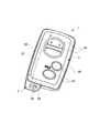
図1は、本実施形態の携帯型無線キーの外観図である。携帯型無線キー1は、対応する車両のドアロックの施錠/開錠を、当該車両のドアに設けられた鍵穴に対し直接的に行うメカニカルキーとしてのエマージェンシーキー2と、エマージェンシーキー2を収容する無線キー本体部3とを有して構成される。エマージェンシーキー2は、無線キー本体部3内の所定の収容部31に対し挿入される形で保持されている。 FIG. 1 is an external view of a portable wireless key according to the present embodiment. The portable wireless key 1 accommodates an
エマージェンシーキー2は、車両ドアの鍵穴に差し込まれるキープレート部2Aと、その端部に設けられたキー把持部2Bとを有する。また、キー把持部2Bには、キープレート部2Aが無線キー本体部3の収容部31内に収容された収容状態において外部に露出する第一の引っ掛け部として吊環部2Cが形成されている。なお、ここでのエマージェンシーキー2は、無線キー本体部3の外周側面30からキー把持部2Bを突出させた状態で無線キー本体部3内に収容保持されている。 The
無線キー本体部3は、角部に面取りがなされた滑らかな外形を有した略直方体形状の筐体形状をなす。その短辺の長さ方向における一方の側から長辺の長さ方向に延びる形で、エマージェンシーキー2の収容部31が形成されている。本実施形態の収容部31は、エマージェンシーキー2のキープレート部2Aを上記長辺の長さ方向に挿入する形で収容しており、収容されたキープレート部2Aの鍵溝に係合する鍵溝係合部(図示なし)を有する。キープレート部2Aの鍵溝と、収容部31の鍵溝係合部とが係合状態となることで、仮抜け止め保持状態(後述のロック解除状態であれば、一定の力以上で引き抜くことは可能)となる。 The wireless
無線キー本体部3は、その厚み方向において上下に分離されており、上側ケース体3Uと下側ケース体3Dとを重ねた形で一体に固定されている。無線キー本体部3の主表面には、ドアロックの施錠及び解除を行うための操作部等、各種の操作部39が設けられている。無線キー本体部3内には、これら操作部が接続される制御部や、この制御部により制御される無線信号の送受信部等が設けられる。なお、こうした携帯型無線キー1の電気的構造については周知であるので説明は省略する。 The wireless key
ところで、本発明の携帯型無線キー1において、無線キー本体部3は、その外周側面30をなす所定位置の操作面30Pに対する1回のプッシュ操作により該無線キー本体部3から外向きに突出する突出動作が生じる突出動作部32を有する。この突出動作によって、無線キー本体部3内にエマージェンシーキー2を収容した状態のまま、当該無線キー本体部3内に収容されている突出動作部32の引っ掛け部33が、携帯型無線キー1の第二の引っ掛け部33として外部に露出して使用可能となることを特徴とする。 By the way, in the portable wireless key 1 of the present invention, the wireless key
以下、本発明の携帯型無線キーの第一実施形態における特徴部について、図2の部分外観図及び図3の分解図を用いて説明する。 Hereinafter, the characteristic part in 1st embodiment of the portable wireless key of this invention is demonstrated using the partial external view of FIG. 2, and the exploded view of FIG.
第一実施形態における突出動作部32は、回動部材321と、回動部材321を無線キー本体部3に対し回動自在に支持する回動軸部322とを有して構成される。回動部材321は、回動軸部322の回転軸線に対して垂直な方向に延出し、その両端部32A,32Bのうち、一方の端部32A側には、無線キー本体部3に設けられた係合部35と係合する係合受け部34と、引っ掛け部33とが設けられている。この係合受け部34と、無線キー本体部3の係合部35とが係合した係合状態にて、突出動作部32が無線キー本体部3内に収容保持されている。 The protruding
回転軸部322は、回動部材321の両端部32A,32Bに対する中間位置に、無線キー本体部3の厚み方向に延びる形で設けられる。ただし、回転軸部322は、両端部32A,32Bのうち、引っ掛け部33及び係合受け部34が設けられている端部32A側に偏った位置に設けられている。 The
回動部材321の両端部32A,32Bのうち、引っ掛け部33及び係合受け部34が設けられていない側に位置する端部32Bの、無線キー本体部3の側方から外部に露出する面30Pは、無線キー本体部3の内向きにプッシュ操作可能な操作面30Pをなす。この操作面30Pに対し上記プッシュ操作がなされると、当該操作面30Pが形成される端部32B側が無線キー本体部3の内側へ押し込まれる一方で、その逆側の端部32A側が無線キー本体部3の外側へ浮き上がるように構成されている。端部32A側が無線キー本体部3の外側へ浮き上がることにより、無線キー本体部3に設けられた係合部35と、端部32Aの係合受け部34との係合状態が物理的に解除されるとともに、引っ掛け部33が無線キー本体部3内から外に突出し、フック等に引っ掛けることが可能となる。 Of the both
操作面30Pは、無線キー本体部3の外周側面30上に、エマージェンシーキー2のキープレート部2A又はそれよりも細い幅の部材(例えばマイナスドライバー等)といった、予め定められた幅を下回る薄い先端部を有した専用ツール(例えばエマージェンシーキー2)によってのみプッシュ操作が可能となる形状にて、無線キー本体部3の外周側面30から外部に露出している。 The
また、回動部材321は、回転軸部322を、無線キー本体部3の内部側に位置させる形で回動自在に支持された板材であり、回転軸部322から遠い側の面320が、無線キー本体部3の外周側面30をなす。操作面30Pは、外周側面30をなす回動部材321の面320のうち、回転軸部322に対する端部32B側の面であり、この面には、専用ツール(例えばエマージェンシーキー2)の先端部と係合させるための凹部32pが形成されている。当該凹部32pの底面を専用ツール(例えばエマージェンシーキー2)の先端部が押圧する形で、上記のプッシュ操作がなされる。凹部32pに専用ツールの先端部が進入した状態で押圧することにより、専用ツールの先端部のすべりが抑制され、プッシュ操作がし易くなっている。 The
無線キー本体部3には、回動部材321を、面320を露出した形で収容する開口30Lが形成されるとともに、その内部には、上記操作面30Pへのプッシュ操作による回動部材321の端部32Bの無線キー本体部3内側への回動変位を許容するための回動変位許容空間3BSが、上側ケース体3Uと下側ケース体3Dとに挟まれた空間として形成されている。一方で、この回動変位許容空間3BSの、無線キー本体部3の内側に形成される壁部(壁面)3Sは、当該回動変位を所定角度位置までに規制する変位規制手段として機能している。これにより、引っ掛け部33が形成される逆側の端部32Aの突出量を一定とすることができ、引っ掛け部33を引っ掛けに適する突出量だけ突出させることを可能とし、過剰な突出を防止している。 The wireless
本実施形態の回動部材321は、全体がL字形状をなして形成されている。L字形状をなす回動部材321は、その長手側延出部32Cの中間位置にて回動軸部322に対し回転自在に取り付けられている。具体的にいえば、本実施形態の回動部材321はL字形状の金属プレートであり、このL字の長手側延出部32Cの中間位置には軸挿通孔部32Dが形成されている。この軸挿通孔部32Dには、無線キー本体部3の外周端部からその厚み方向に突出する円筒状の回転軸部322が挿通され、その円筒状の回転軸部322の先端部への熱カシメにより、軸挿通孔部32D(突出動作部32)が回転軸部322に対し着脱不能で、なおかつ回転自在(ここでは摺動回転可能)となるように平ワッシャを介して取り付けられている。 The
また、本実施形態の突出動作部32は、無線キー本体部3の外周側面30に形成されたL字型の開口30Lを塞ぐ形で設けられ、突出動作部32の当該開口30Lから露出する露出面320が、無線キー本体部3の外周側面30の一部をなすよう、外周側面30から連続的につながる面320となるように形成されている。本実施形態におけるL字型の開口30Lは、無線キー本体部3の4つの角部のうち1つの角部にまたがる形で外周側面30上に形成されており、このL字型の開口30L内にL字形状の突出動作部32が嵌め込まれた形で配置されている。突出動作部32の操作面30Pがプッシュ操作されると、突出動作部32の長手側延出部32Cから屈曲した屈曲部33が無線キー本体部3の外側へ浮き上がり、長手側延出部32Cから屈曲した先の屈曲先端部32Aの先端面(ここでは屈曲先端部32Aの先端のやや内周側の面)32aが無線キー本体部3の開口外縁位置に到達する。この到達位置は、上述した変位規制手段によって決められた位置である。これにより、引っ掛け部33に何かを引っ掛けた時に、その引っ掛けたものが、L字形状の突出動作部32の屈曲内周側と、それに対向する無線キー本体部3の外周側面とで取り囲まれた空間に保持される形となり、外れ難い。 Further, the protruding
本実施形態の引っ掛け部33は、L字形状をなす突出動作部32において長手側延出部32Cの一方の先端から屈曲した屈曲部として形成されている。ここでの引っ掛け部33は、屈曲部の内周側角部といえる。本実施形態の引っ掛け部33は、この屈曲部の内周側角部が外周側角部側に向けて凹んだ凹部として形成されており、より確実に物を引っ掛けることが可能となっている。ここでの凹部は、湾曲面をなす形で形成されている。 The
本実施形態の係合受け部34は、L字形状をなす突出動作部32において長手側延出部32Cの一方の先端から屈曲した先の屈曲先端部32Aにて、無線キー本体部3の厚み方向に凹んだ溝または穴として形成されている。他方、これに係合する無線キー本体部3の係合部35は、無線キー本体部3の厚み方向に突出する突起部として形成されている。 The
本実施形態の無線キー本体部3の突出動作部32は、略直方体形状の筐体形状をなす無線キー本体部3の、略長方形状の主面に対する短辺側の端部に設けられており、さらにいえば、エマージェンシーキー2の取り出し方向とは逆側の端部に設けられている。L字形状をなす突出動作部32は、略直方体形状の筐体形状をなす無線キー本体部3の短辺側に長手側延出部32Cを有し、隣接する長辺側へと屈曲した形状を有する。 The protruding
次に、本発明の携帯型無線キーの第二実施形態における特徴部について、図4の部分外観図及び図5の分解図を用いて説明する。 Next, the characteristic part in 2nd embodiment of the portable wireless key of this invention is demonstrated using the partial external view of FIG. 4, and the exploded view of FIG.
第二実施形態の無線キー本体部3には、収容されているエマージェンシーキー2を取り出し不能にロックするロック機構21と、該ロック機構をロック解除するロック解除操作部22とが設けられ、ロック機構21のロック解除動作と連携する形で、突出動作部32に引っ掛け部33が使用可能となるような突出動作が生ずる。即ち、無線キー本体部3の外周側面30をなす所定位置に対する1回のプッシュ操作によって、ロック機構21のロック状態も解除されて、エマージェンシーキー2の取り出しが可能となると共に、突出動作部32の引っ掛け部33が外部に露出することが可能となる。つまり、ロック機構21のロック解除操作に、突出動作部32に突出動作を生じさせる操作が兼用された構成となっている。 The wireless
なお、突出動作部32の引っ掛け部33を外部に露出させる突出動作を生じさせた上で、その突出状態を保持したまま、ロック機構21をロック状態に戻すことも可能である。つまり、エマージェンシーキー2をロック状態に保持したまま、突出動作部32の引っ掛け部33を使用することも可能である。 It is also possible to return the
無線キー本体部3のロック機構21は、回動部材(可動部材)211と、該回動部材211を無線キー本体部3に対し回動自在に支持する回動軸部212とを有して構成される。回動部材211には、無線キー本体部3内に収容された状態のエマージェンシーキー2の係合受け部23と係合状態となって該エマージェンシーキー2を取り出し不能とする第一係合部24と、突出動作部32の係合受け部25と係合状態となって突出動作部32の引っ掛け部33を無線キー本体部3内に収容保持する第二係合部26とを有する。 The
ロック解除操作部22は、上記のプッシュ操作により、ロック機構21における第一係合部24及び第二係合部26の各々の係合状態を同時に解除することにより、突出動作部32の引っ掛け部33を外部に露出させる突出動作を可能とするものであり、本実施形態の回動部材211のことである。 The lock
本実施形態の回動部材211は、回動軸部212の回転軸線に対して垂直な方向に延出し、その両端部21A,21Bのうち一方21Aの端部に第一係合部24が設けられ、他方の端部21Bに第二係合部26が設けられる。回動部材211は、第二係合部26が設けられた端部21B側に、ロック解除操作部22としてのプッシュ操作の操作面30Pを有する。この操作面30Pが無線キー本体部3の内向きにプッシュ操作がなされた場合には、回動部材211の第一係合部24側の端部21Aが該無線キー本体部3の外側へ浮き上がって第一係合部24の係合受け部23との係合状態が解除されることによりロック機構21のロックが解除される一方で、逆側の第二係合部26側の端部21Bが無線キー本体部3の内側へ押し込まれて第二係合部26の係合受け部25との係合状態が解除されることにより突出動作部32の引っ掛け部33を無線キー本体部3内から外部に露出させる突出動作が可能となるよう構成されている。 The
なお、ロック機構21の回動部材211は、第一係合部24及び第二係合部26のそれぞれが上記のような係合状態となる係合角度位置に位置するよう、ばね部材などの付勢手段27により付勢保持される。操作面30Pへのプッシュ操作は、付勢手段27による付勢力に抗する形でなされ、当該プッシュ操作が解除されるに伴い上記のような係合位置に復帰する。 The
突出動作部32は、回動部材321と、回動部材321を無線キー本体部3に対し回動自在に支持する回動軸部322とを有して構成される。回動部材321は、回動軸部322の回転軸線に対して垂直な方向の両端部32A,32Bのうち、ロック機構21から遠い端部32A側に回動軸部321が設けられ、他方の端部32Aに、ロック機構21の回動部材211の第二係合部26と係合する係合受け部25が設けられる。 The
エマージェンシーキー2には、係合受け部23として鍵溝とは別の溝または穴が設けられる。ロック機構21には、この係合受け部23と係合する第一係合部24として、当該係合受け部23をなす溝または穴への嵌合により係合状態(嵌合状態)となる突起部が設けられている。本実施形態のエマージェンシーキー2には、係合受け部23として、キープレート部2Aの先端部に、無線キー本体部3内に収容された状態で無線キー本体部3の内側から外に向けて貫通する貫通孔23が設けられる一方、ロック機構21の第一係合部24は、無線キー本体部3の外側から内側に突出した突起部24が設けられており、ロック状態においては、この突起部24が貫通孔23内を挿通した状態となる。これにより、エマージェンシーキー2を取り出すことができないようになる。ロック機構21の回動部材211上の操作面30Pに対しプッシュ操作がなされてロック部材211の第一係合部24側の端部21Aが無線キー本体部3の外側へ浮き上がった場合には、突起部24が貫通孔23から外れて、ロック機構21のロックが解除され、エマージェンシーキー2を取り出すことが可能となる。 The
他方、本実施形態の無線キー本体部3の突出動作部32には、係合受け部25として鉤爪状係合受け部が設けられる。ロック機構21には、この鉤爪状係合受け部25と係合する第二係合部26として、当該係合受け部25をなす鉤爪状係合受け部に対し係合状態(嵌合状態)となる鉤爪状係合部が設けられている。即ち、鉤爪状係合受け部25と鉤爪状係合部26とは互いの爪部同士が引っ掛かる形で係合することにより、突出動作部32の端部32A,32Bに対する無線キー本体部3内へ向かうプッシュ操作が生じても突出動作しないようになっている。具体的にいえば、突出動作部32の回動部材321と、ロック機構21の回動動作部211とはL字状に配置されているため、突出動作部32の端部32Aに対しプッシュ操作がなされた場合には、逆側の端部32Aでは、鉤爪状係合受け部25と鉤爪状係合部26とにおける爪部同士の引っ掛かり係合が、ロック機構21の回動動作部211の延出方向に生じ、逆側の端部32Aが無線キー本体部3の外側に浮き上がることが妨げられる一方、突出動作部32の端部32Bに対しプッシュ操作がなされた場合には、ロック機構21の回動部材の延出方向(別の言い方をすれば回動部材211に対し回動軸部322に向かう方向)への力が作用するだけであるから、ロック機構21の回動部材211に動作(回動)は生じないし、突出動作部32にも動作(回動)は生じない。他方、ロック機構21の回動部材211上の操作面30Pに対しプッシュ操作がなされてロック部材211の第二係合部26側の端部21Aが無線キー本体部3の内側へ押し込まれた場合には、鉤爪状係合受け部25と鉤爪状係合部26とにおける爪部同士の引っ掛かり係合が外れて、突出動作部32の引っ掛け部33を外部に露出させる突出動作が可能となる。 On the other hand, the
本実施形態のロック機構21の回転軸部211は、回動部材211の両端部21A,21Bに対する中間位置に、無線キー本体部3の厚み方向に延びる形で設けられる。回動部材211の両端部21A,21Bのうち、突出動作部32側の端部32A側で無線キー本体部3から露出する面が、無線キー本体部3の内向きにプッシュ操作可能な操作面30Pとなっている。 The
本実施形態の回動部材211は、回転軸部212を、無線キー本体部3における内部側に位置させる形で回動自在に支持された板材であり、回転軸部212から遠い側の面210が無線キー本体部3の外周側面30をなす。操作面30Pは、外周側面30をなす回動部材211の面210のうち、回転軸部212に対する端部21B側の面である。 The
本実施形態の無線キー本体部3には、上記プッシュ操作によるロック機構21の回動部材211の端部21Bの無線キー本体部3内側への回動変位を許容するための回動変位許容空間2BSが形成されている。この回動変位許容空間2BSの、無線キー本体部3の内側に形成される壁部(壁面)2Sが、当該回動変位を所定角度位置までに規制する変位規制手段として機能する。 In the wireless
また、本実施形態の無線キー本体部3には、突出動作部32の回動部材321の端部32Bの無線キー本体部3内側への回動変位を許容するための回動変位許容空間3BSが形成されている。この回動変位許容空間3BSの、無線キー本体部3の内側に形成される壁部(壁面)3Sが、当該回動変位を所定角度位置までに規制する変位規制手段として機能する。これにより、引っ掛け部33が形成される逆側の端部32Aの突出量を一定とすることができ、引っ掛け部33を引っ掛けに適する突出量だけ突出させることを可能とし、過剰な突出を防止している。 Further, in the wireless key
本実施形態の突出動作部32には、回動部材321のロック機構21から遠い端部32A側に軸挿通孔部32Dが形成されている。この軸挿通孔部32Dには、無線キー本体部3の外周端部からその厚み方向に突出する円筒状の回転軸部322が挿通され、その円筒状の回転軸部322の先端部への熱カシメにより、軸挿通孔部32D(突出動作部32)が回転軸部322に対し着脱不能で、なおかつ回転自在(ここでは摺動回転可能)となるように平ワッシャを介して取り付けられている。 A
本実施形態の突出動作部32には、回動部材321の端部32Bの、係合受け部25よりも端部32A側の位置に、無線キー本体部3の内側から外側に窪んだ凹部が形成されており、この凹部が引っ掛け部33として形成されている。また、本実施形態においては、突出動作部32の回動部材321が、無線キー本体部3の外周側面30に1つの角部をまたぐ形で形成されたL字型の開口30Mのうち、L字の長手側開口部30M1を塞ぐ形で設けられる。突出動作部32の操作面30Pがプッシュ操作されると、突出動作部32の回動部材321におけるロック機構21側の端部32Bが、無線キー本体部3の外側へと浮き上がることが可能となり、引っ掛け部33をなす凹部の、無線キー本体部3の内側を向く両側先端面33a,33aが無線キー本体部3の開口30M1の外縁位置に到達する。これにより、引っ掛け部33に何かを引っ掛けた時に、その引っ掛けたものが、突出動作部32の内側(無線キー本体部3側)と、それに対向する無線キー本体部3の外周側面とで取り囲まれた空間に保持される形となり、外れ難い。なお、L字の短手側開口30M2は、ロック機構21の回動部材211によって塞がれ形で設けられる。 In the projecting
本実施形態の無線キー本体部3の突出動作部32は、略直方体形状の筐体形状をなす無線キー本体部3の、略長方形状の主面に対する短辺側の端部に設けられており、さらにいえば、エマージェンシーキー2の取り出し方向とは逆側の端部に形成されている。他方、ロック機構21は、無線キー本体部3の両長辺側のうち、エマージェンシーキー2の収容部31が設けられた側の端部の、上記突出動作部32側に形成されている。 The protruding
また、突出動作部32に対し突出動作をさせるプッシュ操作により、略直方体形状の筐体形状をなす無線キー本体部3の形状は、ロック機構21の回動動作(揺動動作)によって、突起の生じた形状となるが、プッシュ操作が解除されれば、付勢手段27の付勢力によって元の形状に戻るため、ロック機構21への操作によって、携帯型無線キー1の全体のデザイン性が損なわれるような状態となることはない。 The shape of the wireless key
上記した第一及び第二の携帯型無線キー1においては、無線キー本体部3内にエマージェンシーキー2を収容した状態において外部に露出して常時使用可能なメインの引っ掛け部(第一の引っ掛け部)2Cと、無線キー本体部3内に収容可能なサブの引っ掛け部(第二の引っ掛け部)33とを有する。サブの引っ掛け部33については、不要な際には、キー1の全体の外観を乱すことの無い形で、無線キー本体部3内に収容しておくことができ、必要な際には、ワンプッシュ操作により外部に露出する突出動作して、容易に使用可能な状態とすることができる。 In the first and second portable wireless keys 1 described above, a main hook portion (first hook portion) that is exposed to the outside and can be used at all times in a state where the
なお、上記第一実施形態においても、第二実施形態と同様のロック機構が設けられているが、第二実施形態のように、突出動作部32の突出動作とは無関係に設けられているため、説明を省略している。 In the first embodiment, the same locking mechanism as that in the second embodiment is provided. However, as in the second embodiment, the locking mechanism is provided regardless of the protruding operation of the protruding
以上、本発明の一実施形態を説明したが、これらはあくまで例示にすぎず、本発明はこれらに限定されるものではなく、特許請求の範囲の趣旨を逸脱しない限りにおいて種々の変更が可能である。 As mentioned above, although one Embodiment of this invention was described, these are only illustrations to the last, and this invention is not limited to these, A various change is possible unless it deviates from the meaning of a claim. is there.
例えば、第二実施形態において、突出動作部32の係合受け部25を引っ掛け部33とするような構成でもよい。この場合、第二実施形態における引っ掛け部33は不要となり、係合受け部25に引っ掛け部33が兼用される構成となる。 For example, in 2nd embodiment, the structure which makes the
1 携帯型無線キー
2 エマージェンシーキー
2A キープレート部
2B キー把持部
2C 吊環部(第一の引っ掛け部)
3 無線キー本体部
30 無線キー本体部の外周側面
30P 操作面
32 突出動作部
321 回動部材
322 回動軸部
33 引っ掛け部(第二の引っ掛け部)
34 係合受け部
35 係合部
21 ロック機構
211 回動部材
212 回動軸部
22 ロック解除操作部
23 係合受け部
24 第一係合部
25 係合受け部
26 第二係合部
27 付勢手段1
3 wireless
34
Claims (12)
Translated fromJapanese前記無線キー本体部は、その外周側面をなす所定位置の操作面に対する1回のプッシュ操作により該無線キー本体部から外向きに突出する突出動作が生じる突出動作部を有し、当該突出動作によって、前記無線キー本体部内に前記エマージェンシーキーを収容した状態のまま、当該無線キー本体部内に収容されている前記突出動作部の引っ掛け部が外部に露出して使用可能となるとともに、
前記突出動作部は、前記無線キー本体部の外周側面上において、前記操作面が前記エマージェンシーキーのキープレート部又はそれよりも細い幅の部材によってのみプッシュ操作が可能となる形状にて露出するとともに、非突出状態における残余の露出面が、当該操作面と同幅をなす形で露出していることを特徴とする携帯型無線キー。A portable wireless key that performs at least control related to locking / unlocking of the door lock of the vehicle by wireless communication with the vehicle side, and locks / unlocks the door lock in the wireless key body. In the portable wireless key that is housed in the form that the emergency key as a mechanical key is inserted and held,
The wireless key main body has a protruding operation portion that generates a protruding operation that protrudes outward from the wireless key main body by a single push operation with respect to an operation surface at a predetermined position that forms an outer peripheral side surface. The hook part of the projecting operation part housed in the wireless key body part is exposed to the outside and can be used while the emergency key is housed in the wireless key body part.
The protruding operation portion is exposed on the outer peripheral side surface of the wireless key body portion in a shape that allows the operation surface to be pushed only by a key plate portion of the emergency key or a member having a narrower width than the operation key. The portable wireless key is characterizedin that the remaining exposed surface in the non-projecting state is exposed in the same width as the operation surface .
前記無線キー本体部は、その外周側面をなす所定位置の操作面に対する1回のプッシュ操作により該無線キー本体部から外向きに突出する突出動作が生じる、前記エマージェンシーキーとは別体の突出動作部を有し、当該突出動作によって、前記無線キー本体部内に前記エマージェンシーキーを収容した状態のまま、当該無線キー本体部内に収容されている前記突出動作部の引っ掛け部が外部に露出して使用可能となるとともに、該引っ掛け部は前記エマージェンシーキーを取り出した後も外部に露出させて使用可能であることを特徴とする携帯型無線キー。A portable wireless key that performs at least control related to locking / unlocking of the door lock of the vehicle by wireless communication with the vehicle side, and locks / unlocks the door lock in the wireless key body. In the portable wireless key that is housed in the form that the emergency key as a mechanical key is inserted and held,
The wireless key main body protrudes outwardly from the wireless key main body by a single push operation on an operation surface at a predetermined position forming an outer peripheral side surface thereof. The protruding operationis separate from the emergency key. And the hooking part of the projecting operation part accommodated in the wireless key body part is exposed to the outside while the emergency key is accommodated in the wireless key body part by the projecting operation. The portable wireless key is characterized in that thehook portion can be used by being exposed to the outside even after the emergency key is taken out .
前記無線キー本体部の外周側面をなす所定位置に対する1回のプッシュ操作によって、前記突出動作部の引っ掛け部を外部に露出させる前記突出動作が可能となると共に、前記ロック機構によるロックが解除されて前記エマージェンシーキーが取り出し可能となる請求項1又は請求項2に記載の携帯型無線キー。The wireless key body is provided with a lock mechanism that locks the stored emergency key so that it cannot be removed, and a lock release operation unit that unlocks the lock mechanism.
The push operation for exposing the hooking portion of the projecting operation portion to the outside is enabled by one push operation with respect to a predetermined position forming the outer peripheral side surface of the wireless key body, and the lock by the lock mechanism is released. The portable wireless key according toclaim 1or 2 , wherein the emergency key can be taken out.
前記無線キー本体部の突出動作部には係合受け部が設けられ、
前記無線キー本体部の前記ロック機構には、該無線キー本体部内に収容された状態の前記エマージェンシーキーの係合受け部と係合状態となって該エマージェンシーキーを取り出し不能とする第一係合部と、前記無線キー本体部の係合受け部と係合状態となって前記突出動作部の引っ掛け部を前記無線キー本体部内に収容保持する第二係合部とを有した可動部材を備え、前記ロック解除操作部は、前記プッシュ操作により、当該可動部材における前記第一係合部及び前記第二係合部の各々の前記係合状態を同時に解除することにより、前記突出動作部の引っ掛け部を外部に露出させる前記突出動作を可能とするものである請求項3に記載の携帯型無線キー。The emergency key is provided with an engagement receiving portion,
An engagement receiving portion is provided in the protruding operation portion of the wireless key body portion,
The lock mechanism of the wireless key main body is engaged with the engagement receiving portion of the emergency key in a state accommodated in the wireless key main body, so that the emergency key cannot be taken out. And a movable member having a second engagement portion that is engaged with the engagement receiving portion of the wireless key main body portion and accommodates and holds the hook portion of the protruding operation portion in the wireless key main body portion. The unlocking operation unit is configured to hook the projecting operation unit by simultaneously releasing the engagement states of the first engagement unit and the second engagement unit of the movable member by the push operation. The portable wireless key according toclaim 3 , wherein the protruding operation of exposing a portion to the outside is enabled.
前記無線キー本体部は、その外周側面をなす所定位置の操作面に対する1回のプッシュ操作により該無線キー本体部から外向きに突出する突出動作が生じる突出動作部を有し、当該突出動作によって、前記無線キー本体部内に前記エマージェンシーキーを収容した状態のまま、当該無線キー本体部内に収容されている前記突出動作部の引っ掛け部が外部に露出して使用可能となる一方、
前記エマージェンシーキーには係合受け部が設けられ、
前記無線キー本体部には、前記突出動作部に係合受け部が設けられ、
さらに前記無線キー本体部には、収容されている前記エマージェンシーキーを取り出し不能にロックするロック機構と、該ロック機構をロック解除するロック解除操作部とが設けられ、
前記ロック機構には、前記無線キー本体部内に収容された状態の前記エマージェンシーキーの係合受け部と係合状態となって該エマージェンシーキーを取り出し不能とする第一係合部と、前記無線キー本体部の係合受け部と係合状態となって前記突出動作部の引っ掛け部を前記無線キー本体部内に収容保持する第二係合部とを有した可動部材が回動部材として設けられ、さらに該回動部材を前記無線キー本体部に対し回動自在に支持する回動軸部が設けられ、
前記回動部材には、前記回動軸部の回動軸に対して垂直な方向の両端部のうち一方の端部に前記第一係合部が設けられ、他方の端部に前記第二係合部が設けられるとともに、該回動部材は、前記第二係合部が設けられる端部側に前記プッシュ操作の操作面を有し、該操作面が前記無線キー本体部の内向きにプッシュ操作がなされた場合には、前記第一係合部側の端部が該無線キー本体部の外側へ浮き上がって前記第一係合部の係合状態が解除されることにより前記ロック機構のロックが解除されて前記エマージェンシーキーが取り出し可能となる一方で、逆側の前記第二係合部側の端部が該無線キー本体部の内側へ押し込まれて前記第二係合部の係合状態が解除されることにより前記突出動作部の引っ掛け部を前記無線キー本体部内から外部に露出させる突出動作が可能となるよう構成されることを特徴とする携帯型無線キー。A portable wireless key that performs at least control related to locking / unlocking of the door lock of the vehicle by wireless communication with the vehicle side, and locks / unlocks the door lock in the wireless key body. In the portable wireless key that is housed in the form that the emergency key as a mechanical key is inserted and held,
The wireless key main body has a protruding operation portion that generates a protruding operation that protrudes outward from the wireless key main body by a single push operation with respect to an operation surface at a predetermined position that forms an outer peripheral side surface. While the emergency key is accommodated in the wireless key body, the hooking portion of the protruding operation part accommodated in the wireless key body is exposed to the outside and can be used.
The emergency key is provided with an engagement receiving portion,
The wireless key body is provided with an engagement receiving portion in the protruding operation portion,
Furthermore, the wireless key main body is provided with a lock mechanism that locks the stored emergency key so that it cannot be removed, and a lock release operation unit that unlocks the lock mechanism.
The lock mechanism includes a first engagement portion that engages with an engagement receiving portion of the emergency key that is housed in the wireless key main body, and that makes it impossible to take out the emergency key; and the wireless key A movable member having a second engagement portion that is engaged with the engagement receiving portion of the main body portion and accommodates and holds the hook portion of the protruding operation portion in the wireless key main body portion is provided as a rotation member, Further, a rotation shaft portion that rotatably supports the rotation member with respect to the wireless key body portion is provided,
The rotating member is provided with the first engaging portion at one end of both ends of the rotating shaft in a direction perpendicular to the rotating shaft, and the second engaging portion at the other end. An engaging portion is provided, and the rotating member has an operation surface for the push operation on an end side where the second engaging portion is provided, and the operation surface faces inward of the wireless key body portion. When a push operation is performed, the end of the first engagement portion is lifted to the outside of the wireless key main body, and the engagement state of the first engagement portion is released, so that the lock mechanism While the lock is released and the emergency key can be taken out, the end on the opposite side of the second engaging portion is pushed into the inside of the wireless key main body to engage the second engaging portion. When the state is released, the hooking portion of the projecting operation portion is moved from the wireless key body portion to the outside. Portable radio key, wherein theconfigured projecting operation of exposed becomes possible.
Priority Applications (2)
| Application Number | Priority Date | Filing Date | Title |
|---|---|---|---|
| JP2010173445AJP5168602B2 (en) | 2010-08-02 | 2010-08-02 | Portable wireless key |
| US13/136,416US8534104B2 (en) | 2010-08-02 | 2011-08-01 | Portable wireless key |
Applications Claiming Priority (1)
| Application Number | Priority Date | Filing Date | Title |
|---|---|---|---|
| JP2010173445AJP5168602B2 (en) | 2010-08-02 | 2010-08-02 | Portable wireless key |
Publications (2)
| Publication Number | Publication Date |
|---|---|
| JP2012031675A JP2012031675A (en) | 2012-02-16 |
| JP5168602B2true JP5168602B2 (en) | 2013-03-21 |
Family
ID=45555070
Family Applications (1)
| Application Number | Title | Priority Date | Filing Date |
|---|---|---|---|
| JP2010173445AExpired - Fee RelatedJP5168602B2 (en) | 2010-08-02 | 2010-08-02 | Portable wireless key |
Country Status (2)
| Country | Link |
|---|---|
| US (1) | US8534104B2 (en) |
| JP (1) | JP5168602B2 (en) |
Cited By (6)
| Publication number | Priority date | Publication date | Assignee | Title |
|---|---|---|---|---|
| US8762733B2 (en) | 2006-01-30 | 2014-06-24 | Adidas Ag | System and method for identity confirmation using physiologic biometrics to determine a physiologic fingerprint |
| US8790255B2 (en) | 2005-07-26 | 2014-07-29 | Adidas Ag | Computer interfaces including physiologically guided avatars |
| US9462975B2 (en) | 1997-03-17 | 2016-10-11 | Adidas Ag | Systems and methods for ambulatory monitoring of physiological signs |
| US9492084B2 (en) | 2004-06-18 | 2016-11-15 | Adidas Ag | Systems and methods for monitoring subjects in potential physiological distress |
| US9504410B2 (en) | 2005-09-21 | 2016-11-29 | Adidas Ag | Band-like garment for physiological monitoring |
| US9833184B2 (en) | 2006-10-27 | 2017-12-05 | Adidas Ag | Identification of emotional states using physiological responses |
Families Citing this family (9)
| Publication number | Priority date | Publication date | Assignee | Title |
|---|---|---|---|---|
| WO2010052003A1 (en)* | 2008-11-05 | 2010-05-14 | Johnson Controls Technology Company | Mechanical module for a vehicle key, and method for making same |
| US10400735B2 (en)* | 2012-05-04 | 2019-09-03 | Light Wave Technology Inc. | System and method for remote starting a vehicle equipped with a smart start system |
| USD710184S1 (en)* | 2012-09-04 | 2014-08-05 | Volkswagen Aktiengesellschaft | Vehicle key |
| USD720603S1 (en)* | 2012-10-15 | 2015-01-06 | Volkswagen Aktiengesellschaft | Vehicle key |
| JP5964765B2 (en)* | 2013-02-21 | 2016-08-03 | トヨタ自動車株式会社 | COMMUNICATION SYSTEM, ON-VEHICLE ELECTRONIC DEVICE, AND COMMUNICATION METHOD |
| US9536365B2 (en) | 2013-05-29 | 2017-01-03 | Lightwave Technology Inc. | System and method for keyless entry and remote starting vehicle with an OEM remote embedded in vehicle |
| USD765609S1 (en)* | 2015-08-25 | 2016-09-06 | Panasonic Intellectual Property Management Co., Ltd. | Remote controller |
| JP6536487B2 (en)* | 2016-05-31 | 2019-07-03 | 株式会社デンソー | Electronic key |
| CN107687290A (en)* | 2017-10-13 | 2018-02-13 | 显亮(昆山)汽车配件有限公司 | A kind of automobile key housing and the automobile key using the housing |
Family Cites Families (16)
| Publication number | Priority date | Publication date | Assignee | Title |
|---|---|---|---|---|
| US1885957A (en)* | 1929-08-15 | 1932-11-01 | Singleton Roscoe Elwood | Automatic key case |
| US5215190A (en)* | 1992-05-19 | 1993-06-01 | Hoffpauir Jr Raymond | Multiple key container housing with selective key projection means |
| US6553802B1 (en)* | 1998-12-16 | 2003-04-29 | Huf Hülsbeck & Fürst Gmbh & Co. Kg | Electronic key, especially for motor vehicles |
| JP3545647B2 (en)* | 1999-06-11 | 2004-07-21 | 株式会社アルファ | Electronic key structure |
| JP2001040921A (en) | 1999-08-03 | 2001-02-13 | Denso Corp | Smart entry system |
| DE10322853A1 (en) | 2003-05-21 | 2004-12-16 | Volkswagen Ag | Key system for a motor vehicle |
| JP2004353404A (en)* | 2003-05-30 | 2004-12-16 | Denso Corp | Portable unit for electronic key system |
| DE10357931B4 (en) | 2003-12-11 | 2006-09-07 | Daimlerchrysler Ag | Electronic key |
| JP4643152B2 (en)* | 2004-01-30 | 2011-03-02 | 株式会社デンソー | Electronic key system portable machine |
| FR2869934B1 (en)* | 2004-05-04 | 2006-07-14 | Valeo Securite Habitacle Sas | RETRACTABLE INSERT KEY HAVING INSERT DRIVING MEANS |
| JP4695463B2 (en)* | 2005-09-01 | 2011-06-08 | 株式会社東海理化電機製作所 | Portable machine |
| JP4555206B2 (en) | 2005-10-17 | 2010-09-29 | 本田技研工業株式会社 | Electronic key for vehicle |
| EP1793351B1 (en)* | 2005-11-29 | 2015-07-15 | Kabushiki Kaisha Tokai-Rika-Denki-Seisakusho | Portable device including mechanical key |
| JP2008008032A (en) | 2006-06-29 | 2008-01-17 | Denso Corp | Portable machine of electronic key system |
| JP4784422B2 (en) | 2006-07-25 | 2011-10-05 | 日本電気株式会社 | Strap mounting structure for portable device and portable device |
| US7634932B2 (en)* | 2006-12-01 | 2009-12-22 | Chrysler Group Llc | Fob integrated key |
- 2010
- 2010-08-02JPJP2010173445Apatent/JP5168602B2/ennot_activeExpired - Fee Related
- 2011
- 2011-08-01USUS13/136,416patent/US8534104B2/ennot_activeExpired - Fee Related
Cited By (7)
| Publication number | Priority date | Publication date | Assignee | Title |
|---|---|---|---|---|
| US9462975B2 (en) | 1997-03-17 | 2016-10-11 | Adidas Ag | Systems and methods for ambulatory monitoring of physiological signs |
| US9750429B1 (en) | 2000-04-17 | 2017-09-05 | Adidas Ag | Systems and methods for ambulatory monitoring of physiological signs |
| US9492084B2 (en) | 2004-06-18 | 2016-11-15 | Adidas Ag | Systems and methods for monitoring subjects in potential physiological distress |
| US8790255B2 (en) | 2005-07-26 | 2014-07-29 | Adidas Ag | Computer interfaces including physiologically guided avatars |
| US9504410B2 (en) | 2005-09-21 | 2016-11-29 | Adidas Ag | Band-like garment for physiological monitoring |
| US8762733B2 (en) | 2006-01-30 | 2014-06-24 | Adidas Ag | System and method for identity confirmation using physiologic biometrics to determine a physiologic fingerprint |
| US9833184B2 (en) | 2006-10-27 | 2017-12-05 | Adidas Ag | Identification of emotional states using physiological responses |
Also Published As
| Publication number | Publication date |
|---|---|
| US20120031155A1 (en) | 2012-02-09 |
| JP2012031675A (en) | 2012-02-16 |
| US8534104B2 (en) | 2013-09-17 |
Similar Documents
| Publication | Publication Date | Title |
|---|---|---|
| JP5168602B2 (en) | Portable wireless key | |
| JP5557829B2 (en) | Vehicle portable device | |
| US7823427B2 (en) | Cylinder lock device | |
| US6718805B2 (en) | Steering wheel locking device | |
| CN108571235B (en) | Unlocking mechanism, lockset and vehicle | |
| JP4712590B2 (en) | Steering lock device | |
| JP2004162261A (en) | Slot mechanism | |
| JP2011111800A (en) | Rotating operation support structure of mechanical key provided to electronic key | |
| JP4087655B2 (en) | A portable machine containing a mechanical key | |
| US11149468B2 (en) | Electronic key | |
| US8042367B2 (en) | Tumbler-type key verification system | |
| JP4865390B2 (en) | Electronic key | |
| JP4555206B2 (en) | Electronic key for vehicle | |
| JP4206292B2 (en) | Key cylinder operation knob | |
| JP2007277921A (en) | Portable apparatus | |
| JP2011219994A (en) | Portable machine for vehicle | |
| JP2005220702A (en) | Remote controller | |
| JP2007032123A (en) | Portable machine | |
| JP2006132271A (en) | Portable machine | |
| JP4537175B2 (en) | Key cylinder operation knob | |
| KR102474427B1 (en) | Retractable key unit for vehicles | |
| JP4902410B2 (en) | Engine start switch | |
| JP3651316B2 (en) | Locking device | |
| JP2007284876A (en) | Electronic key | |
| JP4044340B2 (en) | Locking device |
Legal Events
| Date | Code | Title | Description |
|---|---|---|---|
| A621 | Written request for application examination | Free format text:JAPANESE INTERMEDIATE CODE: A621 Effective date:20120124 | |
| A977 | Report on retrieval | Free format text:JAPANESE INTERMEDIATE CODE: A971007 Effective date:20120712 | |
| A131 | Notification of reasons for refusal | Free format text:JAPANESE INTERMEDIATE CODE: A131 Effective date:20120718 | |
| A521 | Written amendment | Free format text:JAPANESE INTERMEDIATE CODE: A523 Effective date:20120918 | |
| RD02 | Notification of acceptance of power of attorney | Free format text:JAPANESE INTERMEDIATE CODE: A7422 Effective date:20121003 | |
| TRDD | Decision of grant or rejection written | ||
| A01 | Written decision to grant a patent or to grant a registration (utility model) | Free format text:JAPANESE INTERMEDIATE CODE: A01 Effective date:20121129 | |
| A61 | First payment of annual fees (during grant procedure) | Free format text:JAPANESE INTERMEDIATE CODE: A61 Effective date:20121212 | |
| FPAY | Renewal fee payment (event date is renewal date of database) | Free format text:PAYMENT UNTIL: 20160111 Year of fee payment:3 | |
| LAPS | Cancellation because of no payment of annual fees |