JP5166014B2 - Equipment for removing dissolved hydrogen sulfide in anaerobic treatment - Google Patents
Equipment for removing dissolved hydrogen sulfide in anaerobic treatmentDownload PDFInfo
- Publication number
- JP5166014B2 JP5166014B2JP2007337807AJP2007337807AJP5166014B2JP 5166014 B2JP5166014 B2JP 5166014B2JP 2007337807 AJP2007337807 AJP 2007337807AJP 2007337807 AJP2007337807 AJP 2007337807AJP 5166014 B2JP5166014 B2JP 5166014B2
- Authority
- JP
- Japan
- Prior art keywords
- tank
- water tank
- anaerobic treatment
- anaerobic
- biological desulfurization
- Prior art date
- Legal status (The legal status is an assumption and is not a legal conclusion. Google has not performed a legal analysis and makes no representation as to the accuracy of the status listed.)
- Expired - Fee Related
Links
Images


Classifications
- B—PERFORMING OPERATIONS; TRANSPORTING
- B01—PHYSICAL OR CHEMICAL PROCESSES OR APPARATUS IN GENERAL
- B01D—SEPARATION
- B01D19/00—Degasification of liquids
- B01D19/0005—Degasification of liquids with one or more auxiliary substances
- B01D19/001—Degasification of liquids with one or more auxiliary substances by bubbling steam through the liquid
- B—PERFORMING OPERATIONS; TRANSPORTING
- B01—PHYSICAL OR CHEMICAL PROCESSES OR APPARATUS IN GENERAL
- B01D—SEPARATION
- B01D19/00—Degasification of liquids
- B01D19/0068—General arrangements, e.g. flowsheets
- B—PERFORMING OPERATIONS; TRANSPORTING
- B01—PHYSICAL OR CHEMICAL PROCESSES OR APPARATUS IN GENERAL
- B01D—SEPARATION
- B01D53/00—Separation of gases or vapours; Recovering vapours of volatile solvents from gases; Chemical or biological purification of waste gases, e.g. engine exhaust gases, smoke, fumes, flue gases, aerosols
- B01D53/34—Chemical or biological purification of waste gases
- B01D53/46—Removing components of defined structure
- B01D53/48—Sulfur compounds
- B01D53/52—Hydrogen sulfide
- B—PERFORMING OPERATIONS; TRANSPORTING
- B01—PHYSICAL OR CHEMICAL PROCESSES OR APPARATUS IN GENERAL
- B01D—SEPARATION
- B01D53/00—Separation of gases or vapours; Recovering vapours of volatile solvents from gases; Chemical or biological purification of waste gases, e.g. engine exhaust gases, smoke, fumes, flue gases, aerosols
- B01D53/34—Chemical or biological purification of waste gases
- B01D53/74—General processes for purification of waste gases; Apparatus or devices specially adapted therefor
- B01D53/84—Biological processes
- C—CHEMISTRY; METALLURGY
- C02—TREATMENT OF WATER, WASTE WATER, SEWAGE, OR SLUDGE
- C02F—TREATMENT OF WATER, WASTE WATER, SEWAGE, OR SLUDGE
- C02F1/00—Treatment of water, waste water, or sewage
- C02F1/20—Treatment of water, waste water, or sewage by degassing, i.e. liberation of dissolved gases
- C—CHEMISTRY; METALLURGY
- C02—TREATMENT OF WATER, WASTE WATER, SEWAGE, OR SLUDGE
- C02F—TREATMENT OF WATER, WASTE WATER, SEWAGE, OR SLUDGE
- C02F3/00—Biological treatment of water, waste water, or sewage
- C02F3/28—Anaerobic digestion processes
- C—CHEMISTRY; METALLURGY
- C02—TREATMENT OF WATER, WASTE WATER, SEWAGE, OR SLUDGE
- C02F—TREATMENT OF WATER, WASTE WATER, SEWAGE, OR SLUDGE
- C02F3/00—Biological treatment of water, waste water, or sewage
- C02F3/30—Aerobic and anaerobic processes
- C—CHEMISTRY; METALLURGY
- C12—BIOCHEMISTRY; BEER; SPIRITS; WINE; VINEGAR; MICROBIOLOGY; ENZYMOLOGY; MUTATION OR GENETIC ENGINEERING
- C12M—APPARATUS FOR ENZYMOLOGY OR MICROBIOLOGY; APPARATUS FOR CULTURING MICROORGANISMS FOR PRODUCING BIOMASS, FOR GROWING CELLS OR FOR OBTAINING FERMENTATION OR METABOLIC PRODUCTS, i.e. BIOREACTORS OR FERMENTERS
- C12M21/00—Bioreactors or fermenters specially adapted for specific uses
- C12M21/04—Bioreactors or fermenters specially adapted for specific uses for producing gas, e.g. biogas
- C—CHEMISTRY; METALLURGY
- C12—BIOCHEMISTRY; BEER; SPIRITS; WINE; VINEGAR; MICROBIOLOGY; ENZYMOLOGY; MUTATION OR GENETIC ENGINEERING
- C12M—APPARATUS FOR ENZYMOLOGY OR MICROBIOLOGY; APPARATUS FOR CULTURING MICROORGANISMS FOR PRODUCING BIOMASS, FOR GROWING CELLS OR FOR OBTAINING FERMENTATION OR METABOLIC PRODUCTS, i.e. BIOREACTORS OR FERMENTERS
- C12M47/00—Means for after-treatment of the produced biomass or of the fermentation or metabolic products, e.g. storage of biomass
- C12M47/18—Gas cleaning, e.g. scrubbers; Separation of different gases
- B—PERFORMING OPERATIONS; TRANSPORTING
- B01—PHYSICAL OR CHEMICAL PROCESSES OR APPARATUS IN GENERAL
- B01D—SEPARATION
- B01D2251/00—Reactants
- B01D2251/10—Oxidants
- B01D2251/11—Air
- B—PERFORMING OPERATIONS; TRANSPORTING
- B01—PHYSICAL OR CHEMICAL PROCESSES OR APPARATUS IN GENERAL
- B01D—SEPARATION
- B01D2251/00—Reactants
- B01D2251/95—Specific microorganisms
- B—PERFORMING OPERATIONS; TRANSPORTING
- B01—PHYSICAL OR CHEMICAL PROCESSES OR APPARATUS IN GENERAL
- B01D—SEPARATION
- B01D2258/00—Sources of waste gases
- B01D2258/05—Biogas
- B—PERFORMING OPERATIONS; TRANSPORTING
- B01—PHYSICAL OR CHEMICAL PROCESSES OR APPARATUS IN GENERAL
- B01D—SEPARATION
- B01D53/00—Separation of gases or vapours; Recovering vapours of volatile solvents from gases; Chemical or biological purification of waste gases, e.g. engine exhaust gases, smoke, fumes, flue gases, aerosols
- B01D53/34—Chemical or biological purification of waste gases
- B01D53/74—General processes for purification of waste gases; Apparatus or devices specially adapted therefor
- B01D53/77—Liquid phase processes
- C—CHEMISTRY; METALLURGY
- C02—TREATMENT OF WATER, WASTE WATER, SEWAGE, OR SLUDGE
- C02F—TREATMENT OF WATER, WASTE WATER, SEWAGE, OR SLUDGE
- C02F2101/00—Nature of the contaminant
- C02F2101/10—Inorganic compounds
- C02F2101/101—Sulfur compounds
- C—CHEMISTRY; METALLURGY
- C02—TREATMENT OF WATER, WASTE WATER, SEWAGE, OR SLUDGE
- C02F—TREATMENT OF WATER, WASTE WATER, SEWAGE, OR SLUDGE
- C02F2103/00—Nature of the water, waste water, sewage or sludge to be treated
- C02F2103/18—Nature of the water, waste water, sewage or sludge to be treated from the purification of gaseous effluents
- C—CHEMISTRY; METALLURGY
- C02—TREATMENT OF WATER, WASTE WATER, SEWAGE, OR SLUDGE
- C02F—TREATMENT OF WATER, WASTE WATER, SEWAGE, OR SLUDGE
- C02F2303/00—Specific treatment goals
- C02F2303/02—Odour removal or prevention of malodour
- C—CHEMISTRY; METALLURGY
- C02—TREATMENT OF WATER, WASTE WATER, SEWAGE, OR SLUDGE
- C02F—TREATMENT OF WATER, WASTE WATER, SEWAGE, OR SLUDGE
- C02F3/00—Biological treatment of water, waste water, or sewage
- C02F3/02—Aerobic processes
- C—CHEMISTRY; METALLURGY
- C02—TREATMENT OF WATER, WASTE WATER, SEWAGE, OR SLUDGE
- C02F—TREATMENT OF WATER, WASTE WATER, SEWAGE, OR SLUDGE
- C02F9/00—Multistage treatment of water, waste water or sewage
- Y—GENERAL TAGGING OF NEW TECHNOLOGICAL DEVELOPMENTS; GENERAL TAGGING OF CROSS-SECTIONAL TECHNOLOGIES SPANNING OVER SEVERAL SECTIONS OF THE IPC; TECHNICAL SUBJECTS COVERED BY FORMER USPC CROSS-REFERENCE ART COLLECTIONS [XRACs] AND DIGESTS
- Y02—TECHNOLOGIES OR APPLICATIONS FOR MITIGATION OR ADAPTATION AGAINST CLIMATE CHANGE
- Y02A—TECHNOLOGIES FOR ADAPTATION TO CLIMATE CHANGE
- Y02A50/00—TECHNOLOGIES FOR ADAPTATION TO CLIMATE CHANGE in human health protection, e.g. against extreme weather
- Y02A50/20—Air quality improvement or preservation, e.g. vehicle emission control or emission reduction by using catalytic converters
- Y—GENERAL TAGGING OF NEW TECHNOLOGICAL DEVELOPMENTS; GENERAL TAGGING OF CROSS-SECTIONAL TECHNOLOGIES SPANNING OVER SEVERAL SECTIONS OF THE IPC; TECHNICAL SUBJECTS COVERED BY FORMER USPC CROSS-REFERENCE ART COLLECTIONS [XRACs] AND DIGESTS
- Y02—TECHNOLOGIES OR APPLICATIONS FOR MITIGATION OR ADAPTATION AGAINST CLIMATE CHANGE
- Y02E—REDUCTION OF GREENHOUSE GAS [GHG] EMISSIONS, RELATED TO ENERGY GENERATION, TRANSMISSION OR DISTRIBUTION
- Y02E50/00—Technologies for the production of fuel of non-fossil origin
- Y02E50/30—Fuel from waste, e.g. synthetic alcohol or diesel
- Y—GENERAL TAGGING OF NEW TECHNOLOGICAL DEVELOPMENTS; GENERAL TAGGING OF CROSS-SECTIONAL TECHNOLOGIES SPANNING OVER SEVERAL SECTIONS OF THE IPC; TECHNICAL SUBJECTS COVERED BY FORMER USPC CROSS-REFERENCE ART COLLECTIONS [XRACs] AND DIGESTS
- Y02—TECHNOLOGIES OR APPLICATIONS FOR MITIGATION OR ADAPTATION AGAINST CLIMATE CHANGE
- Y02W—CLIMATE CHANGE MITIGATION TECHNOLOGIES RELATED TO WASTEWATER TREATMENT OR WASTE MANAGEMENT
- Y02W10/00—Technologies for wastewater treatment
- Y02W10/10—Biological treatment of water, waste water, or sewage
Landscapes
- Engineering & Computer Science (AREA)
- Chemical & Material Sciences (AREA)
- Life Sciences & Earth Sciences (AREA)
- Health & Medical Sciences (AREA)
- Organic Chemistry (AREA)
- Environmental & Geological Engineering (AREA)
- Microbiology (AREA)
- Biomedical Technology (AREA)
- Bioinformatics & Cheminformatics (AREA)
- Chemical Kinetics & Catalysis (AREA)
- Zoology (AREA)
- Wood Science & Technology (AREA)
- Biotechnology (AREA)
- Genetics & Genomics (AREA)
- Oil, Petroleum & Natural Gas (AREA)
- Molecular Biology (AREA)
- Hydrology & Water Resources (AREA)
- General Chemical & Material Sciences (AREA)
- Water Supply & Treatment (AREA)
- General Health & Medical Sciences (AREA)
- General Engineering & Computer Science (AREA)
- Biochemistry (AREA)
- Analytical Chemistry (AREA)
- Sustainable Development (AREA)
- Biodiversity & Conservation Biology (AREA)
- Purification Treatments By Anaerobic Or Anaerobic And Aerobic Bacteria Or Animals (AREA)
- Gas Separation By Absorption (AREA)
- Physical Water Treatments (AREA)
- Degasification And Air Bubble Elimination (AREA)
- Treatment Of Sludge (AREA)
Description
Translated fromJapanese本発明は、嫌気性処理における溶存硫化水素の除去方法に関する。 The present invention relates to a method for removing dissolved hydrogen sulfide in anaerobic treatment.
周知の如く、下水や産業排水などの有機性排水を浄化する方法として嫌気性処理法が知られている。嫌気性処理法では嫌気性微生物の働きで有機物を分解する。その副産物として、メタン、炭酸ガス、硫化水素を含んだバイオガスを生成する。バイオガスは、ガス中の硫化水素を除去(脱硫)することでガスボイラー等の燃料として利用することができる。しかし、生成した硫化水素は嫌気性処理槽の液相内に溶存しており、嫌気性処理水が悪臭を放つことが懸念される。また、硫化水素は、嫌気性微生物の活性を阻害して排水処理の効率の低下を招く恐れがある。 As is well known, an anaerobic treatment method is known as a method for purifying organic wastewater such as sewage and industrial wastewater. In the anaerobic treatment method, organic substances are decomposed by the action of anaerobic microorganisms. As a byproduct, biogas containing methane, carbon dioxide and hydrogen sulfide is generated. Biogas can be used as a fuel for a gas boiler or the like by removing (desulfurizing) hydrogen sulfide in the gas. However, the produced hydrogen sulfide is dissolved in the liquid phase of the anaerobic treatment tank, and there is a concern that the anaerobic treated water gives off a bad odor. In addition, hydrogen sulfide may inhibit the activity of anaerobic microorganisms and cause a reduction in the efficiency of wastewater treatment.
従来、嫌気性処理水に溶存する硫化水素を除去する方法として、嫌気性処理槽に空気を吹き込む方法(例えば、特許文献1参照)が知られている。また、嫌気性反応槽に溶存する硫化水素を除去する方法として、密閉型嫌気性反応槽と密閉型調整槽とで該調整槽内の処理水の一部を循環させ、前記反応槽及び調整槽のいずれかの気相部内にある発酵ガスから硫化水素を除去した後、前記反応槽及び調整槽のいずれかの液相部内に曝気する方法(例えば、特許文献2参照)が知られている。 Conventionally, as a method of removing hydrogen sulfide dissolved in anaerobic treated water, a method of blowing air into an anaerobic treatment tank (for example, see Patent Document 1) is known. Further, as a method of removing hydrogen sulfide dissolved in the anaerobic reaction tank, a part of the treated water in the adjustment tank is circulated between the sealed anaerobic reaction tank and the sealed adjustment tank, and the reaction tank and the adjustment tank A method is known in which hydrogen sulfide is removed from the fermentation gas in any one of the gas phase parts and then aerated in any one of the liquid phase parts of the reaction tank and the adjustment tank (see, for example, Patent Document 2).
更に、脱硫方法の一つに生物脱硫が知られている。生物脱硫は、硫黄酸化細菌の働きで硫化水素を酸化することによりバイオガスから除去する。生物脱硫では微生物の生育のため栄養塩を含んだ水分を供給する。この水分は硫化水素をバイオガスから吸収し、硫化水素が酸化され生成した生成物を排出する役割も有する。そして、生物脱硫では酸化に必要な酸素として通常空気を供給する。
本発明は、こうした事情を考慮してなされたもので、嫌気性消化槽で生成するバイオガスを脱硫する方法として生物脱硫を用いた場合において、嫌気性処理槽に溶存する硫化水素を低減しえる嫌気性処理における溶存硫化水素の除去装置を提供することを目的とする。 The present invention has been made in consideration of such circumstances, and when biodesulfurization is used as a method for desulfurizing biogas generated in an anaerobic digestion tank, hydrogen sulfide dissolved in the anaerobic treatment tank can be reduced. An object of the present invention is to provide a device for removing dissolved hydrogen sulfide in anaerobic treatment.
本発明の嫌気性処理における溶存硫化水素の除去装置は、次の(1)〜(5)である。
(1)有機性排水を嫌気性処理する嫌気性処理槽と、この嫌気性処理槽との間で循環ポンプによって溶液を循環する循環水槽と、前記嫌気性処理槽と循環水槽間で循環する循環水へ有機性排水を注入する注入手段と、前記循環水槽から排出された嫌気性処理水を一時貯留する処理水槽と、嫌気性処理で生成したバイオガスの脱硫を行う生物脱硫塔と、この生物脱硫塔へ空気を供給する空気供給手段と、前記生物脱硫塔へ水を供給する水供給手段と、前記生物脱硫塔からの生物脱硫処理ガスの一部を前記処理水槽に吹き込む散気手段と、前記処理水槽から排出される排気を前記循環水槽へ吹き込む散気手段と、前記循環水槽から排出される排気を前記生物脱硫塔へ返送する返送手段を具備することを特徴とする嫌気性処理における溶存硫化水素の除去装置。The apparatus for removing dissolved hydrogen sulfide in the anaerobic treatment of the present invention is the following (1) to (5).
(1) An anaerobic treatment tank for anaerobically treating organic waste water, a circulating water tank for circulating the solution by a circulation pump between the anaerobic treatment tank, and a circulation for circulation between the anaerobic treatment tank and the circulating water tank An injecting means for injecting organic wastewater into water, a treated water tank for temporarily storing anaerobic treated water discharged from the circulating water tank, a biological desulfurization tower for desulfurizing biogas generated by anaerobic treatment, Air supply means for supplying air to the desulfurization tower, water supply means for supplying water to the biological desulfurization tower, aeration means for blowing a part of the biological desulfurization treatment gas from the biological desulfurization tower into the treated water tank, Dissolving in anaerobic treatment characterized by comprising a diffuser for blowing exhaust discharged from the treated water tank into the circulating water tank and a returning means for returning the exhaust discharged from the circulating water tank to the biological desulfurization tower Hydrogen sulfide Removal device.
(2)有機性排水を嫌気性処理する嫌気性処理槽と、この嫌気性処理槽との間で循環ポンプによって溶液を循環する循環水槽と、前記嫌気性処理槽と循環水槽間で循環する循環水へ有機性排水を注入する注入手段と、前記循環水槽から排出された嫌気性処理水を一時貯留する処理水槽と、嫌気性処理で生成したバイオガスの脱硫を行う生物脱硫塔と、この生物脱硫塔へ空気を供給する空気供給手段と、前記生物脱硫塔へ水を供給する水供給手段と、前記生物脱硫塔からの生物脱硫処理ガスの一部を前記処理水槽に吹き込む散気手段と、前記処理水槽から排出される排気を前記嫌気性処理槽へ吹き込む散気手段を具備することを特徴とする嫌気性処理における溶存硫化水素の除去装置。 (2) An anaerobic treatment tank for anaerobically treating organic waste water, a circulating water tank for circulating a solution between the anaerobic treatment tank by a circulation pump, and a circulation for circulation between the anaerobic treatment tank and the circulating water tank. An injecting means for injecting organic wastewater into water, a treated water tank for temporarily storing anaerobic treated water discharged from the circulating water tank, a biological desulfurization tower for desulfurizing biogas generated by anaerobic treatment, Air supply means for supplying air to the desulfurization tower, water supply means for supplying water to the biological desulfurization tower, aeration means for blowing a part of the biological desulfurization treatment gas from the biological desulfurization tower into the treated water tank, An apparatus for removing dissolved hydrogen sulfide in anaerobic treatment, comprising a diffuser for blowing exhaust gas discharged from the treated water tank into the anaerobic treatment tank.
(3)有機性排水を嫌気性処理する嫌気性処理槽と、この嫌気性処理槽との間で循環ポンプによって溶液を循環する循環水槽と、前記嫌気性処理槽と循環水槽間で循環する循環水へ有機性排水を注入する注入手段と、前記循環水槽から排出された嫌気性処理水を一時貯留する処理水槽と、嫌気性処理で生成したバイオガスの脱硫を行う生物脱硫塔と、この生物脱硫塔へ空気を供給する空気供給手段と、前記生物脱硫塔へ水を供給する水供給手段と、前記生物脱硫塔からの生物脱硫処理ガスの一部を前記処理水槽に吹き込む散気手段と、前記処理水槽から排出される排気を前記循環水槽へ吹き込む散気手段と、前記循環水槽から排出される排気を嫌気性処理槽へ吹き込む散気手段を具備することを特徴とする嫌気性処理における溶存硫化水素の除去装置。 (3) An anaerobic treatment tank for anaerobically treating organic waste water, a circulating water tank for circulating the solution by a circulation pump between the anaerobic treatment tank, and a circulation for circulation between the anaerobic treatment tank and the circulating water tank. An injecting means for injecting organic wastewater into water, a treated water tank for temporarily storing anaerobic treated water discharged from the circulating water tank, a biological desulfurization tower for desulfurizing biogas generated by anaerobic treatment, Air supply means for supplying air to the desulfurization tower, water supply means for supplying water to the biological desulfurization tower, aeration means for blowing a part of the biological desulfurization treatment gas from the biological desulfurization tower into the treated water tank, Dissolving in anaerobic treatment characterized by comprising a diffuser for blowing exhaust discharged from the treated water tank into the circulating water tank and a diffuser for blowing exhaust discharged from the circulating water tank into the anaerobic treated tank Of hydrogen sulfide Removed by the device.
(4)有機性排水を嫌気性処理する嫌気性処理槽と、この嫌気性処理槽との間で循環ポンプによって溶液を循環する循環水槽と、前記嫌気性処理槽と循環水槽間で循環する循環水へ有機性排水を注入する注入手段と、嫌気性処理で生成したバイオガスの脱硫を行う生物脱硫塔と、この生物脱硫塔へ空気を供給する空気供給手段と、前記生物脱硫塔へ水を供給する水供給手段と、嫌気処理水を好気処理する手段と、好気処理で発生する余剰汚泥を一時貯留する汚泥貯留槽と、前記生物脱硫塔からの生物脱硫処理ガスの一部を前記汚泥貯留槽に吹き込む散気手段と、前記汚泥貯留槽から排出される排気を前記循環水槽へ吹き込む散気手段と、前記循環水槽から排出される排気を生物脱硫塔へ返送する返送手段を具備することを特徴とする嫌気性処理における溶存硫化水素の除去装置。 (4) An anaerobic treatment tank for anaerobically treating organic waste water, a circulating water tank for circulating the solution between the anaerobic treatment tank by a circulation pump, and a circulation for circulating between the anaerobic treatment tank and the circulating water tank. Injecting means for injecting organic wastewater into water, biological desulfurization tower for desulfurizing biogas generated by anaerobic treatment, air supply means for supplying air to the biological desulfurization tower, and water to the biological desulfurization tower Water supply means for supplying, means for aerobic treatment of anaerobic treated water, sludge storage tank for temporarily storing surplus sludge generated by aerobic treatment, and part of the biological desulfurization treatment gas from the biological desulfurization tower Aeration means for blowing into the sludge storage tank, aeration means for blowing the exhaust discharged from the sludge storage tank into the circulating water tank, and a return means for returning the exhaust discharged from the circulating water tank to the biological desulfurization tower. Anaerobic treatment characterized by Apparatus for removing dissolved hydrogen sulfide in.
(5)有機性排水を嫌気性処理する嫌気性処理槽と、この嫌気性処理槽との間で循環ポンプによって溶液を循環する循環水槽と、前記嫌気性処理槽と循環水槽間で循環する循環水へ有機性排水を注入する注入手段と、前記循環水槽から排出された嫌気性処理水を一時貯留する処理水槽と、嫌気性処理で生成したバイオガスの脱硫を行う第1の生物脱硫塔と、この第1の生物脱硫塔への空気を供給する空気供給手段と、前記第1の生物脱硫塔へ水を供給する水供給手段と、前記第1の生物脱硫塔からの処理ガスとバイオガスが送られ,バイオガスの脱硫を行う第2の生物脱硫塔と、この第2の生物脱硫塔へ水を供給する水供給手段と、前記第2の生物脱硫塔からの処理ガスの一部を循環水槽に吹き込む散気手段と、前記循環水槽から排出される排気を生物脱硫塔へ返送する返送手段を具備することを特徴とする嫌気性処理における溶存硫化水素の除去装置。 (5) An anaerobic treatment tank for anaerobically treating organic waste water, a circulating water tank for circulating the solution between the anaerobic treatment tank by a circulation pump, and a circulation for circulation between the anaerobic treatment tank and the circulating water tank. Injecting means for injecting organic waste water into water, a treated water tank for temporarily storing anaerobic treated water discharged from the circulating water tank, and a first biological desulfurization tower for desulfurizing biogas generated by anaerobic treatment An air supply means for supplying air to the first biological desulfurization tower, a water supply means for supplying water to the first biological desulfurization tower, a processing gas and a biogas from the first biological desulfurization tower A second biological desulfurization tower for desulfurizing biogas, water supply means for supplying water to the second biological desulfurization tower, and a part of the processing gas from the second biological desulfurization tower Aeration means for blowing into the circulating water tank and discharged from the circulating water tank Apparatus for removing dissolved hydrogen sulfide in an anaerobic process, characterized by comprising a returning means for returning the air to the biological desulfurization tower.
本発明によれば、嫌気性消化槽で生成するバイオガスを脱硫する方法として生物脱硫を用いた場合において、嫌気性処理槽に溶存する硫化水素を低減しえる嫌気性処理における溶存硫化水素の除去装置を提供できる。 According to the present invention, when biodesulfurization is used as a method of desulfurizing biogas generated in an anaerobic digestion tank, removal of dissolved hydrogen sulfide in anaerobic treatment that can reduce hydrogen sulfide dissolved in the anaerobic treatment tank. Equipment can be provided.
以下、本発明に係る嫌気性処理における溶存硫化水素の除去装置の実施例について、図面を参照して説明する。なお、本発明は下記に述べるものに限定されない。
(実施例1)(請求項1に対応)
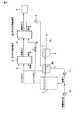
図1は、本発明の実施例1に係る嫌気性処理における溶存硫化水素の除去装置を概略的なブロック図で示したものである。
図中の符番1は、有機性排水を嫌気性処理する嫌気性処理槽である。この嫌気性処理槽1には循環ポンプ2を介して循環水槽3が接続され、嫌気性処理槽1と循環水槽3との間で循環ポンプ2によって溶液(循環水)が循環するようになっている。嫌気性処理槽1と循環水槽3間で循環する循環水には、図示しない注入手段により有機性排水が注入される。有機性排水は嫌気性処理槽1の下部で循環水に注入される。有機性排水は、嫌気性処理槽1に保持された嫌気性微生物の働きにより分解され、浄化される。浄化された処理水は、循環水槽3を経て処理水槽4に一時貯留され、その後河川や下水道へ放流される。処理水槽4からの処理水排水管7は、水封されている。なお、図中の符番7aは、処理水排水管7の水封部を示す。Hereinafter, embodiments of a device for removing dissolved hydrogen sulfide in an anaerobic treatment according to the present invention will be described with reference to the drawings. In addition, this invention is not limited to what is described below.
Example 1 (corresponding to claim 1)
FIG. 1 is a schematic block diagram showing an apparatus for removing dissolved hydrogen sulfide in anaerobic processing according to
嫌気性処理槽1で生成したバイオガスは、生物脱硫塔5へ送られて脱硫される。この生物脱硫塔5には、空気供給手段(図示せず)により空気が供給され、水供給手段(図示せず)により水が供給される。生物脱硫塔5では、硫黄酸化細菌の働きにより硫化水素が酸化される。酸化された生成物は、水と共に排水として排出される。脱硫後の処理ガスは、ガスボイラー6に送られて燃料として利用される。生物脱硫塔5からの処理ガスの一部は送風ファン8により処理水槽4へ散気管(散気手段)9aを通して吹き込まれる。処理水槽9から排気される排気は、循環水槽3へ散気管(散気手段)9bを通して吹き込まれる。循環水槽4から排出される排気は、図示しない返送手段によりバイオガスとともに嫌気性処理槽1からの生物脱硫塔5へ返送される。 The biogas generated in the
次に、図1の溶存硫化水素の除去装置の作用について説明する。
生物脱硫塔5の処理ガスには、硫化水素はほとんど含まれないが、生物脱硫塔5での酸化反応に用いられなかった酸素が残存している。従って、処理ガスを処理水槽4に吹き込むと、嫌気状態の処理水で処理ガス中の酸素は消費される。また、処理水槽4からの排気を循環水槽3へ吹き込むことで、循環水槽3への酸素の持ち込みがなくなる。そして、循環による嫌気性処理槽1へ酸素の持ち込みもない。従って、嫌気性処理槽1に保持される嫌気性微生物の酸素による活性低下が避けられる。Next, the operation of the dissolved hydrogen sulfide removing device shown in FIG. 1 will be described.
The treatment gas of the
処理水槽4からの排気を循環水槽3へ吹き込むと、処理ガス中に含まれる硫化水素濃度が低いため、循環している嫌気性処理槽1の液相に溶存している硫化水素は気相に放散(巣トリッピング)し、除去される。放散した硫化水素を含む循環水槽3からの排気はバイオガスに混合されて生物脱硫塔5に戻され、硫化水素は除去される。これにより液相に溶存する硫化水素濃度が低減し、処理水から悪臭が発生することが避けられる。 When exhaust gas from the
また、処理水槽4に接続する処理水排水管7が水封されることで、処理ガスをバイオガスに循環させる図1のような構成で懸念される点、即ちバイオガスの循環水槽3への逆流が起こり圧力差により処理水排水管7を経由してバイオガスが外部へ漏れたり、送風ファン8の圧力によって処理ガスが処理水排水管7を経て漏れたりすることが抑制される。 Further, since the treated water drain pipe 7 connected to the treated
上述したように、実施例1に係る溶存硫化水素の除去装置は、嫌気性処理槽1と、この嫌気性処理1槽との間で循環ポンプ2によって溶液を循環する循環水槽3と、循環水槽3から排出された嫌気性処理水を一時貯留する処理水槽4と、バイオガスの脱硫を行う生物脱硫塔5と、生物脱硫塔5からの生物脱硫処理ガスの一部を処理水槽4に吹き込む散気管9aと、処理水槽4からの排気を循環水槽3へ吹き込む散気管(散気手段)9bを具備し、循環水へ有機性排水を注入するとともに、生物脱硫塔5へ空気及び水を供給するように構成されている。 As described above, the device for removing dissolved hydrogen sulfide according to the first embodiment includes the
実施例1によれば、以下に述べる効果を有する。
即ち、生物脱硫塔5の処理ガスの一部を処理水槽4への吹き込み、その排気を循環水槽3に吹き込み、その排気を生物脱硫塔5に返送することで、嫌気性処理槽1の液相に溶存する硫化水素濃度を低減でき、嫌気性微生物の硫化水素による活性低下を回避できる。従って、嫌気性処理性能が高く維持できる。
また、同様な理由により、嫌気性処理水の硫化水素濃度が低減でき、処理水から悪臭が発生することが避けられる。
更には、同様な理由により、生物脱硫塔5の処理ガスに含まれる残存酸素濃度が低減することで処理ガスのメタン濃度が増加し、バイオガスの単位流量当たりのエネルギー量を増加することができる。The first embodiment has the following effects.
That is, a part of the treatment gas in the
For the same reason, the concentration of hydrogen sulfide in anaerobic treated water can be reduced, and the generation of malodor from the treated water can be avoided.
Furthermore, for the same reason, the methane concentration of the processing gas is increased by reducing the residual oxygen concentration contained in the processing gas of the
(実施例2)(請求項2に対応)
図2は、本発明の実施例2に係る嫌気性処理における溶存硫化水素の除去装置を概略的なブロック図で示したものである。但し、図1と同部材は同符番を付し、説明を省略する。
実施例2の溶存硫化水素の除去装置は、実施例1の除去装置では処理水槽4からの排気を循環水槽3に吹き込むのに対し、処理水槽4からの排気を嫌気性処理槽1へ散気管(散気手段)9cを通して吹き込む点が異なる。(Example 2) (corresponding to claim 2)
FIG. 2 is a schematic block diagram showing an apparatus for removing dissolved hydrogen sulfide in anaerobic processing according to
The apparatus for removing dissolved hydrogen sulfide of Example 2 is that the exhaust from the
実施例2に係る溶存硫化水素の除去装置は、図2に示すように、嫌気性処理槽1と、この嫌気性処理1槽との間で循環ポンプ2によって溶液を循環する循環水槽3と、循環水槽3から排出された嫌気性処理水を一時貯留する処理水槽4と、バイオガスの脱硫を行う生物脱硫塔5と、生物脱硫塔5からの生物脱硫処理ガスの一部を処理水槽4に吹き込む散気管9aと、処理水槽4からの排気を嫌気性処理槽1へ吹き込む散気管(散気手段)9cを具備し、循環水へ有機性排水を注入するとともに、生物脱硫塔5へ空気及び水を供給するように構成されている。 As shown in FIG. 2, the device for removing dissolved hydrogen sulfide according to Example 2 includes an
実施例2によれば、以下に述べる効果を有する。
即ち、生物脱硫塔5の処理ガスの一部を処理水槽4への吹き込み、その排気を嫌気性処理槽1に吹き込み、その排気を生物脱硫塔5に返送することで、嫌気性処理槽1の液相に溶存する硫化水素濃度を低減でき、嫌気性微生物の硫化水素による活性低下を回避できる。従って、嫌気性処理性能が高く維持できる。
また、同様な理由により、嫌気性処理水の硫化水素濃度が低減でき、処理水から悪臭が発生することが避けられる。更には、同様な理由により、生物脱硫塔5の処理ガスに含まれる残存酸素濃度が低減することで処理ガスのメタン濃度が増加し、バイオガスの単位流量当たりのエネルギー量を増加することができる。The second embodiment has the following effects.
That is, a part of the treatment gas in the
For the same reason, the concentration of hydrogen sulfide in the anaerobic treated water can be reduced, and the generation of malodor from the treated water can be avoided. Furthermore, for the same reason, the methane concentration of the processing gas is increased by reducing the residual oxygen concentration contained in the processing gas of the
(実施例3)(請求項3に対応)
図3は、本発明の実施例3に係る嫌気性処理における溶存硫化水素の除去装置を概略的なブロック図で示したものである。但し、図1,2と同部材は同符番を付し、説明を省略する。
実施例3の溶存硫化水素の除去装置は、実施例1の除去装置では処理水槽4からの排気を循環水槽3に吹き込むのに対し、処理水槽4からの排気を循環水槽3に吹き込むとともに、循環水槽3からの排気を散気管9cを通して嫌気性処理槽1へ吹き込む点が異なる。Example 3 (corresponding to claim 3)
FIG. 3 is a schematic block diagram showing an apparatus for removing dissolved hydrogen sulfide in anaerobic processing according to
The apparatus for removing dissolved hydrogen sulfide of Example 3 is that the exhaust from the treated
実施例3に係る溶存硫化水素の除去装置は、図3に示すように、嫌気性処理槽1と、この嫌気性処理1槽との間で循環ポンプ2によって溶液を循環する循環水槽3と、循環水槽3から排出された嫌気性処理水を一時貯留する処理水槽4と、バイオガスの脱硫を行う生物脱硫塔5と、生物脱硫塔5からの生物脱硫処理ガスの一部を処理水槽4に吹き込む散気管9aと、処理水槽4からの排気を循環水槽3に吹き込む散気管9bと、循環水槽3からの排気を嫌気性処理槽1に吹き込む散気管9cを具備し、循環水へ有機性排水を注入するとともに、生物脱硫塔5へ空気及び水を供給するように構成されている。 As shown in FIG. 3, the device for removing dissolved hydrogen sulfide according to Example 3 includes an
実施例3によれば、以下に述べる効果を有する。
即ち、生物脱硫塔5の処理ガスの一部を処理水槽4への吹き込み、その排気を循環水槽3へ、更に循環水槽3からの排気を嫌気性処理槽1に吹き込み、その排気を生物脱硫塔5に返送することで、嫌気性処理槽1の液相に溶存する硫化水素濃度を低減でき、嫌気性微生物の硫化水素による活性低下を回避できる。従って、嫌気性処理性能が高く維持できる。
また、同様な理由により、嫌気性処理水の硫化水素濃度が低減でき、処理水から悪臭が発生することが避けられる。更には、同様な理由により、生物脱硫塔5の処理ガスに含まれる残存酸素濃度が低減することで処理ガスのメタン濃度が増加し、バイオガスの単位流量当たりのエネルギー量を増加することができる。Example 3 has the following effects.
That is, a part of the treatment gas from the
For the same reason, the concentration of hydrogen sulfide in the anaerobic treated water can be reduced, and the generation of malodor from the treated water can be avoided. Furthermore, for the same reason, the methane concentration of the processing gas is increased by reducing the residual oxygen concentration contained in the processing gas of the
(実施例4)(請求項4に対応)
図4は、本発明の実施例4に係る嫌気性処理における溶存硫化水素の除去装置を概略的なブロック図で示したものである。但し、図1,2と同部材は同符番を付し、説明を省略する。
図中の符番21は嫌気処理水を活性汚泥法によって好気処理する好気処理手段であり、符番22は好気処理で発生する余剰汚泥を一時貯留する汚泥貯留槽である。好気処理手段21は、活性汚泥の働きによって嫌気処理水を好気処理する反応槽23と、活性汚泥と好気処理水とを分離する沈殿池24と、汚泥返送ポンプ25aと、汚泥引抜ポンプ25bと、反応槽23において散気管9dを通して空気を散気するブロア27を備えている。汚泥返送ポンプ25aは、沈殿池24の底部の汚泥を反応槽23に返送するためのものである。汚泥引抜ポンプ25bは、沈殿池24の底部の汚泥を汚泥貯留槽22に送るためのものである。なお、図中の符番9eは、汚泥貯留槽22に配置された散気管である。Example 4 (corresponding to claim 4)
FIG. 4 is a schematic block diagram showing an apparatus for removing dissolved hydrogen sulfide in anaerobic processing according to
こうした構成の溶存硫化水素の除去装置において、生物脱硫塔5からの生物脱硫処理ガスの一部は、送風ファン8により散気管9eを通して汚泥貯留槽22に吹き込まれる。これにより、嫌気状態の汚泥で処理ガス中の酸素は消費される。また、汚泥貯留槽22からの排気は、排気管9bを通して循環水槽3に吹き込まれる。これにより、循環水槽3への酸素の持ち込みがなくなる。
一方、循環水槽3からの嫌気処理水配管28は、水封部28aで水封されている。また、沈殿池24からの汚泥は汚泥引抜ポンプ25aにより反応槽23に返送されるとともに、汚泥引抜ポンプ25bにより汚泥貯留槽22に返送される。ここで、汚泥貯留槽22での余剰汚泥は、外部に取り出される。更に、沈殿池24からの好気処理水は外部に取り出される。In the device for removing dissolved hydrogen sulfide having such a configuration, part of the biological desulfurization processing gas from the
On the other hand, the anaerobic treated
実施例4によれば、以下に述べる効果を有する。
即ち、生物脱硫塔5の処理ガスの一部を汚泥貯留槽22に吹き込むので、嫌気状態の汚泥で処理ガス中の酸素は消費される。また、汚泥貯留槽22からの排気は、排気管9bを通して循環水槽3に吹き込まれるので、循環水槽3への酸素の持ち込みがなくなる。更に、循環水槽3からの嫌気性処理水は嫌気処理水配管28の水封部28aで水封され、反応槽23からは好気処理水が沈殿池24を通って外部に排出される。従って、実施例1と同様に、嫌気性処理性能を高く維持できるとともに、処理水から悪臭の発生を回避でき、更にバイオガスの単位流量当たりのエネルギー量を増加することができる。Example 4 has the following effects.
That is, since a part of the processing gas of the
(実施例5)(請求項5に対応)
図5は、本発明の実施例5に係る嫌気性処理における溶存硫化水素の除去装置を概略的なブロック図で示したものである。但し、図1,2と同部材は同符番を付し、説明を省略する。
図中の符番31は、嫌気性処理槽1で生成したバイオガスの脱硫を行う第1の生物脱硫塔を示す。符番32は、第1の生物脱硫塔31からの処理ガスとバイオガスが送られ,バイオガスの脱硫を行う第2の生物脱硫塔を示す。符番33は嫌気性処理槽1から第2の生物脱硫塔32に供給されるバイオガスの流量を調節するための流量調節バルブを示す。更に、符番34は、循環水へ有機性排水を送る給液ポンプを示す。ここで、第2の生物脱硫塔32では、第1の生物脱硫塔31からの処理ガス中の酸素を消費するように流量が調節されたバイオガスを供給するため、第2の生物脱硫塔32内の酸素は略零である。第1の生物脱硫塔31からの処理ガス中の酸素濃度は、処理ガスを採取して分析することで得ることができる。処理ガス中の酸素を消費するバイオガスの流量は、バイオガスを採取して硫化水素濃度を分析することにより得た硫化水素濃度と処理ガス中の酸素濃度とによって化学量論的に得ることができる。Example 5 (corresponding to claim 5)
FIG. 5 is a schematic block diagram showing an apparatus for removing dissolved hydrogen sulfide in anaerobic processing according to
Reference numeral 31 in the figure indicates a first biological desulfurization tower that performs desulfurization of the biogas generated in the
実施例5に係る溶存硫化水素の除去装置は、図5に示すように、第1の生物脱硫塔31,第2の生物脱硫塔32を直列に設けることにより、実施例1と同様に、嫌気性処理性能を高く維持できるとともに、処理水から悪臭の発生を回避でき、更にバイオガスの単位流量当たりのエネルギー量を増加することができる他、第2の生物脱硫塔32からの処理ガス中の酸素を略零にすることができる。 As shown in FIG. 5, the apparatus for removing dissolved hydrogen sulfide according to Example 5 is anaerobic as in Example 1 by providing a first biological desulfurization tower 31 and a second biological desulfurization tower 32 in series. In addition to being able to avoid the generation of malodor from the treated water, and further to increase the amount of energy per unit flow rate of the biogas, in the treated gas from the second biological desulfurization tower 32 Oxygen can be made substantially zero.
なお、本発明は、上記実施形態そのままに限定されるものではなく、実施段階ではその要旨を逸脱しない範囲で構成要素を変形して具体化できる。また、上記実施形態に開示されている複数の構成要素の適宜な組み合せにより種々の発明を形成できる。例えば、実施形態に示される全構成要素から幾つかの構成要素を削除してもよい。更に、異なる実施形態に亘る構成要素を適宜組み合せてもよい。 Note that the present invention is not limited to the above-described embodiment as it is, and can be embodied by modifying the constituent elements without departing from the scope of the invention in the implementation stage. Further, various inventions can be formed by appropriately combining a plurality of constituent elements disclosed in the embodiment. For example, some components may be deleted from all the components shown in the embodiment. Furthermore, you may combine suitably the component covering different embodiment.
1…嫌気性処理槽、2…循環ポンプ、3…循環水槽、4…処理水槽、5,31,32…生物脱硫塔、4…処理水槽、6…ガスボイラー、7,28…処理水排水管、7a,28a…水封部、8…送風ファン、9a,9b,9c,9d,9e…散気管、21…好気処理手段、22…汚泥貯留槽、23…反応槽、24…沈殿池、25a,25b…汚泥引抜ポンプ、26…ブロア、33…流量調節バルブ、34…給液ポンプ。 DESCRIPTION OF
Claims (5)
Translated fromJapaneseこの嫌気性処理槽との間で循環ポンプによって溶液を循環する循環水槽と、
前記嫌気性処理槽と循環水槽間で循環する循環水へ有機性排水を注入する注入手段と、
前記循環水槽から排出された嫌気性処理水を一時貯留する処理水槽と、
嫌気性処理で生成したバイオガスの脱硫を行う生物脱硫塔と、
この生物脱硫塔へ空気を供給する空気供給手段と、
前記生物脱硫塔へ水を供給する水供給手段と、
前記生物脱硫塔からの生物脱硫処理ガスの一部を前記処理水槽に吹き込む散気手段と、
前記処理水槽から排出される排気を前記循環水槽へ吹き込む散気手段と、
前記循環水槽から排出される排気を前記生物脱硫塔へ返送する返送手段を具備することを特徴とする嫌気性処理における溶存硫化水素の除去装置。An anaerobic treatment tank for anaerobically treating organic wastewater;
A circulating water tank that circulates the solution between the anaerobic treatment tank and a circulation pump;
Injection means for injecting organic wastewater into the circulating water circulating between the anaerobic treatment tank and the circulating water tank;
A treated water tank for temporarily storing anaerobic treated water discharged from the circulating water tank;
A biodesulfurization tower for desulfurization of biogas generated by anaerobic treatment;
An air supply means for supplying air to the biological desulfurization tower;
Water supply means for supplying water to the biological desulfurization tower;
Aeration means for blowing a part of the biological desulfurization treatment gas from the biological desulfurization tower into the treated water tank;
Aeration means for blowing the exhaust discharged from the treated water tank into the circulating water tank;
An apparatus for removing dissolved hydrogen sulfide in anaerobic treatment, comprising a return means for returning exhaust gas discharged from the circulating water tank to the biological desulfurization tower.
Priority Applications (4)
| Application Number | Priority Date | Filing Date | Title |
|---|---|---|---|
| JP2007337807AJP5166014B2 (en) | 2007-12-27 | 2007-12-27 | Equipment for removing dissolved hydrogen sulfide in anaerobic treatment |
| US12/528,897US8163179B2 (en) | 2007-12-27 | 2008-12-12 | Apparatus for removing dissolved hydrogen sulfide in anaerobic treatment |
| CN2008800064468ACN101622202B (en) | 2007-12-27 | 2008-12-12 | Apparatus for removing dissolved hydrogen sulfide in anaerobic treatment |
| PCT/JP2008/072616WO2009084405A1 (en) | 2007-12-27 | 2008-12-12 | Apparatus for removing dissolved hydrogen sulfide in anaerobic treatment |
Applications Claiming Priority (1)
| Application Number | Priority Date | Filing Date | Title |
|---|---|---|---|
| JP2007337807AJP5166014B2 (en) | 2007-12-27 | 2007-12-27 | Equipment for removing dissolved hydrogen sulfide in anaerobic treatment |
Publications (2)
| Publication Number | Publication Date |
|---|---|
| JP2009154131A JP2009154131A (en) | 2009-07-16 |
| JP5166014B2true JP5166014B2 (en) | 2013-03-21 |
Family
ID=40824126
Family Applications (1)
| Application Number | Title | Priority Date | Filing Date |
|---|---|---|---|
| JP2007337807AExpired - Fee RelatedJP5166014B2 (en) | 2007-12-27 | 2007-12-27 | Equipment for removing dissolved hydrogen sulfide in anaerobic treatment |
Country Status (4)
| Country | Link |
|---|---|
| US (1) | US8163179B2 (en) |
| JP (1) | JP5166014B2 (en) |
| CN (1) | CN101622202B (en) |
| WO (1) | WO2009084405A1 (en) |
Families Citing this family (6)
| Publication number | Priority date | Publication date | Assignee | Title |
|---|---|---|---|---|
| CA2843041C (en) | 2013-02-22 | 2017-06-13 | Anschutz Exploration Corporation | Method and system for removing hydrogen sulfide from sour oil and sour water |
| US9364773B2 (en) | 2013-02-22 | 2016-06-14 | Anschutz Exploration Corporation | Method and system for removing hydrogen sulfide from sour oil and sour water |
| US11440815B2 (en) | 2013-02-22 | 2022-09-13 | Anschutz Exploration Corporation | Method and system for removing hydrogen sulfide from sour oil and sour water |
| US9708196B2 (en) | 2013-02-22 | 2017-07-18 | Anschutz Exploration Corporation | Method and system for removing hydrogen sulfide from sour oil and sour water |
| JP6820079B2 (en)* | 2017-03-28 | 2021-01-27 | 住友重機械エンバイロメント株式会社 | Water treatment equipment |
| CN111689659B (en)* | 2020-07-13 | 2023-11-24 | 福建中盟环保有限公司 | Integrated vertical high-concentration sulfate wastewater treatment device |
Family Cites Families (11)
| Publication number | Priority date | Publication date | Assignee | Title |
|---|---|---|---|---|
| JPS56161896A (en)* | 1980-05-20 | 1981-12-12 | Agency Of Ind Science & Technol | Anaerobic digestion |
| JPH0226615A (en)* | 1988-07-12 | 1990-01-29 | Fuso Yunitetsuku Kk | Desulfurization apparatus for digester gas |
| JPH03270792A (en)* | 1990-03-20 | 1991-12-02 | Toshiba Corp | Anaerobic water treatment equipment |
| JPH0716594A (en) | 1993-06-17 | 1995-01-20 | Toshiba Corp | Wastewater treatment equipment |
| JPH0716593A (en)* | 1993-07-01 | 1995-01-20 | Toshiba Corp | Wastewater treatment equipment |
| JPH07148495A (en)* | 1993-11-29 | 1995-06-13 | Mitsubishi Kakoki Kaisha Ltd | Method for anaerobic treatment of organic waste water |
| NL9401036A (en)* | 1994-06-23 | 1996-02-01 | Tno | Anaerobic removal of sulfur compounds from wastewater. |
| JP3270792B2 (en) | 1994-06-24 | 2002-04-02 | 京セラ株式会社 | Method for producing silicon nitride based sintered body |
| US7060233B1 (en)* | 2002-03-25 | 2006-06-13 | Tda Research, Inc. | Process for the simultaneous removal of sulfur and mercury |
| JP4611204B2 (en)* | 2003-07-16 | 2011-01-12 | 荏原エンジニアリングサービス株式会社 | Method and apparatus for anaerobic treatment of wastewater containing sulfur compounds |
| JP4299168B2 (en)* | 2004-03-22 | 2009-07-22 | 住友重機械エンバイロメント株式会社 | Anaerobic treatment equipment |
- 2007
- 2007-12-27JPJP2007337807Apatent/JP5166014B2/ennot_activeExpired - Fee Related
- 2008
- 2008-12-12WOPCT/JP2008/072616patent/WO2009084405A1/enactiveApplication Filing
- 2008-12-12USUS12/528,897patent/US8163179B2/ennot_activeExpired - Fee Related
- 2008-12-12CNCN2008800064468Apatent/CN101622202B/ennot_activeExpired - Fee Related
Also Published As
| Publication number | Publication date |
|---|---|
| JP2009154131A (en) | 2009-07-16 |
| WO2009084405A1 (en) | 2009-07-09 |
| US8163179B2 (en) | 2012-04-24 |
| CN101622202A (en) | 2010-01-06 |
| US20100101985A1 (en) | 2010-04-29 |
| CN101622202B (en) | 2011-09-07 |
Similar Documents
| Publication | Publication Date | Title |
|---|---|---|
| JP4610977B2 (en) | Method and apparatus for treating sludge return water | |
| JP5197223B2 (en) | Water treatment system | |
| JP5355459B2 (en) | Organic wastewater treatment system | |
| JP5166014B2 (en) | Equipment for removing dissolved hydrogen sulfide in anaerobic treatment | |
| JP4465628B2 (en) | Biological treatment method and apparatus for nitrous oxide gas | |
| JP2000263084A (en) | Waste water treatment equipment and waste water treatment method | |
| JP3918349B2 (en) | Biological treatment method and apparatus for nitrous oxide gas | |
| JP2002079034A (en) | Biological desulfurization method and apparatus | |
| JP2002292393A (en) | Apparatus and method for methane fermentation | |
| JP4631162B2 (en) | Organic waste treatment methods | |
| JP2006167512A (en) | Methane fermentation product processing apparatus and method | |
| JP2004148242A (en) | Waste water treatment method and waste water treatment equipment | |
| JP4299168B2 (en) | Anaerobic treatment equipment | |
| JP2001232388A (en) | Method and apparatus for treating waste liquor | |
| JP2005288371A (en) | Wastewater treatment method | |
| JP6113611B2 (en) | Organic wastewater treatment system | |
| JPH11333492A (en) | Apparatus and method for methane fermentation | |
| JP5930798B2 (en) | Organic wastewater treatment method and apparatus | |
| JP2011212562A (en) | Method for treating organic wastewater | |
| JP2002079294A (en) | Biological desulfurization method and apparatus | |
| JP6753106B2 (en) | Organic wastewater treatment equipment | |
| JP2003024980A (en) | Wastewater treatment equipment | |
| KR100514765B1 (en) | The system for treating odorous compounds | |
| JP5873744B2 (en) | Organic wastewater and organic waste treatment method and treatment equipment | |
| JP3200936B2 (en) | Odor gas deodorization method in anaerobic treatment |
Legal Events
| Date | Code | Title | Description |
|---|---|---|---|
| A621 | Written request for application examination | Free format text:JAPANESE INTERMEDIATE CODE: A621 Effective date:20100201 | |
| RD04 | Notification of resignation of power of attorney | Free format text:JAPANESE INTERMEDIATE CODE: A7424 Effective date:20120529 | |
| TRDD | Decision of grant or rejection written | ||
| A01 | Written decision to grant a patent or to grant a registration (utility model) | Free format text:JAPANESE INTERMEDIATE CODE: A01 Effective date:20121127 | |
| A61 | First payment of annual fees (during grant procedure) | Free format text:JAPANESE INTERMEDIATE CODE: A61 Effective date:20121220 | |
| FPAY | Renewal fee payment (event date is renewal date of database) | Free format text:PAYMENT UNTIL: 20151228 Year of fee payment:3 | |
| R151 | Written notification of patent or utility model registration | Ref document number:5166014 Country of ref document:JP Free format text:JAPANESE INTERMEDIATE CODE: R151 | |
| FPAY | Renewal fee payment (event date is renewal date of database) | Free format text:PAYMENT UNTIL: 20151228 Year of fee payment:3 | |
| LAPS | Cancellation because of no payment of annual fees |