JP5165867B2 - Stereoscopic microscope system with epi-illumination device - Google Patents
Stereoscopic microscope system with epi-illumination deviceDownload PDFInfo
- Publication number
- JP5165867B2 JP5165867B2JP2006208087AJP2006208087AJP5165867B2JP 5165867 B2JP5165867 B2JP 5165867B2JP 2006208087 AJP2006208087 AJP 2006208087AJP 2006208087 AJP2006208087 AJP 2006208087AJP 5165867 B2JP5165867 B2JP 5165867B2
- Authority
- JP
- Japan
- Prior art keywords
- light emitting
- emitting diodes
- focus adjustment
- adjustment arm
- illumination
- Prior art date
- Legal status (The legal status is an assumption and is not a legal conclusion. Google has not performed a legal analysis and makes no representation as to the accuracy of the status listed.)
- Active
Links
- 238000005286illuminationMethods0.000titleclaimsdescription60
- NJPPVKZQTLUDBO-UHFFFAOYSA-NnovaluronChemical compoundC1=C(Cl)C(OC(F)(F)C(OC(F)(F)F)F)=CC=C1NC(=O)NC(=O)C1=C(F)C=CC=C1FNJPPVKZQTLUDBO-UHFFFAOYSA-N0.000claimsdescription16
- 230000003287optical effectEffects0.000claimsdescription14
- 239000000853adhesiveSubstances0.000claimsdescription3
- 230000001070adhesive effectEffects0.000claimsdescription3
- 238000011109contaminationMethods0.000claimsdescription3
- 238000009304pastoral farmingMethods0.000claimsdescription2
- 239000007787solidSubstances0.000claims1
- 238000006073displacement reactionMethods0.000description6
- 230000001419dependent effectEffects0.000description2
- 230000002730additional effectEffects0.000description1
- 230000005540biological transmissionEffects0.000description1
- 238000001816coolingMethods0.000description1
- 239000003365glass fiberSubstances0.000description1
- 238000003384imaging methodMethods0.000description1
- 238000000034methodMethods0.000description1
- 230000003362replicative effectEffects0.000description1
- 230000003595spectral effectEffects0.000description1
- 239000000126substanceSubstances0.000description1
Images


Classifications
- G—PHYSICS
- G02—OPTICS
- G02B—OPTICAL ELEMENTS, SYSTEMS OR APPARATUS
- G02B21/00—Microscopes
- G02B21/18—Arrangements with more than one light path, e.g. for comparing two specimens
- G02B21/20—Binocular arrangements
- G02B21/22—Stereoscopic arrangements
Landscapes
- Physics & Mathematics (AREA)
- Chemical & Material Sciences (AREA)
- Analytical Chemistry (AREA)
- General Physics & Mathematics (AREA)
- Optics & Photonics (AREA)
- Microscoopes, Condenser (AREA)
Description
Translated fromJapanese本発明は、落射照明装置を備える立体(実体)顕微鏡システムに関する。本発明は、詳細には、落射照明装置を備える立体顕微鏡システムであって、焦点調節柱を固定した台座を有するシステムに関する。台座に垂直な装置軸を規定する立体顕微鏡を支持する焦点調節アームは、焦点調節柱に摺動可能に取り付けられる。立体顕微鏡は、グリノー(Greenough)式の実施形態でもよいし、又は主対物レンズを有する望遠鏡式であってもよい。また、立体顕微鏡は、焦点調節アームに着脱可能に連結されてもよいし、又は焦点調節アームと一体化されてもよい。 The present invention relates to a stereoscopic (substance) microscope system including an epi-illumination device. More particularly, the present invention relates to a stereoscopic microscope system including an epi-illumination device, and a system having a pedestal to which a focusing column is fixed. A focus adjustment arm that supports a stereoscopic microscope that defines a device axis perpendicular to the pedestal is slidably attached to the focus adjustment column. The stereomicroscope may be a Greenough embodiment or a telescope with a main objective. Further, the stereo microscope may be detachably connected to the focus adjustment arm, or may be integrated with the focus adjustment arm.
特許文献1は、照明用平面状支持体に設けられた複数の発光ダイオードを有する立体顕微鏡を開示する。発光ダイオード(複数)から構成される第2の照明装置が、斜照明用に、対物レンズの開口の近傍にある焦点調節アームに付加的に設けられている。発光ダイオード(複数)を有する第3の照明装置は、環状型の形態であり、立体顕微鏡の対物レンズの開口の周りに取り付け可能である。 Patent Document 1 discloses a stereoscopic microscope having a plurality of light emitting diodes provided on a planar support for illumination. A second illuminating device comprising a plurality of light emitting diodes is additionally provided on the focus adjustment arm near the aperture of the objective lens for oblique illumination. The third illumination device having the light emitting diode (s) is in the form of a ring and can be mounted around the aperture of the objective lens of the stereoscopic microscope.
特許文献2は、落射光試料照明装置を開示する。落射光試料照明装置は、複数の個別切換可能光源(自己発光要素、グラスファイバ、又は背後から照明される絞り)を有する。光源は、好適には、異なる平面で複数の同心円に配置され、光は、これらの光源から、異なる光軸で発光される。これにより、照明は、光源又は画像化要素を機械的に変位調節することなく、様々な照明角度が選択可能となる。各光源は、半球状の支持体に固定される。この支持体は、顕微鏡又は観察装置の対物レンズの周囲に配置される。 Patent document 2 discloses an epi-illumination sample illumination device. The epi-illumination sample illumination device has a plurality of individually switchable light sources (self-luminous element, glass fiber, or diaphragm illuminated from behind). The light sources are preferably arranged in a plurality of concentric circles in different planes, and light is emitted from these light sources with different optical axes. This allows illumination to be selected from various illumination angles without mechanically adjusting the light source or imaging element. Each light source is fixed to a hemispherical support. This support is arranged around the objective lens of the microscope or observation apparatus.
特許文献3は、光源を使用する医療処置用装置を開示する。外科用視野の照明用光源は、発光ダイオードとして構成され、発光ダイオードが発する光線が光軸に対して5°〜80°の角度で外科用視野を照らすように配置される。
特許文献4は、光軸周りに配向されると共に照明手段を受容する環状の支持体を有する顕微鏡における、特に落射照明用の、照明装置及び方法を開示する。発光ダイオード(複数)は、環状支持体に、少なくとも2つの同心円を形成するように取り付けられる。環状支持体は、顕微鏡の対物レンズの光軸に対して対称に配置される。発光ダイオード(複数)は、比較的小さい照射角を有し、顕微鏡の光軸方向を指向するか又は光軸方向に傾いている。白色光発光ダイオードがダイオードとして使用される。また、発光ダイオード(複数)は、グループで合わせて接続することができ、また制御可能な定電流電源によって操作される。 U.S. Patent No. 6,057,031 discloses an illumination apparatus and method, particularly for epi-illumination, in a microscope having an annular support oriented around the optical axis and receiving illumination means. The light emitting diodes are attached to the annular support so as to form at least two concentric circles. The annular support is arranged symmetrically with respect to the optical axis of the objective lens of the microscope. The light emitting diodes have a relatively small irradiation angle and are oriented in the optical axis direction of the microscope or tilted in the optical axis direction. A white light emitting diode is used as the diode. The light emitting diodes can be connected together in groups and are operated by a controllable constant current power source.
立体顕微鏡の対物レンズの開口の周りに配置される特許文献1の照明装置の本質的な欠点は、照明装置が独立した要素となるので、紛失しやすく、また盗難もされやすくなることである。特許文献3の装置は、様々な照明条件の設定について何も述べておらず、また発光ダイオードが顕微鏡又は立体顕微鏡用の照明システムに使用可能であることについても言及していない。特許文献4の欠点は、発光ダイオードが、盗難されやすく、又は紛失しやすい独立した支持体上に取り付けられていることである。 An essential drawback of the illumination device of Patent Document 1 arranged around the objective lens aperture of the stereomicroscope is that the illumination device is an independent element and thus is easily lost and stolen. The device of
本発明の基礎となる課題は、落射照明装置を備える立体顕微鏡システムであって、機械的に変位させることなく種々の落射照明モードを実施することができ、また、これらの種々の落射照明条件を達成するために、付加的要素を立体顕微鏡に連結する必要のない立体顕微鏡システムを提供することである。 A problem underlying the present invention is a stereoscopic microscope system including an epi-illumination device, which can implement various epi-illumination modes without being mechanically displaced, and can satisfy these various epi-illumination conditions. To achieve, it is to provide a stereomicroscope system that does not require additional elements to be coupled to the stereomicroscope.
本発明の課題は、請求項1の特徴を有する、落射照明装置を備える立体顕微鏡システムによって達成される。即ち、本発明の立体顕微鏡は、焦点調節柱が固定された台座、及び焦点調節柱に移動可能に取り付けられると共に、台座に対して垂直な装置軸を規定する立体顕微鏡を支持する受容開口と、円弧状下面部とを備えた焦点調節アーム、を有し、点光源として複数の第1発光ダイオードが、焦点調節アームの受容開口周りに配置されていると共に、縦方向落射照明に利用可能であり、点光源として複数の第2発光ダイオードが、前記焦点調節アームの前記円弧状下面部において、焦点調節柱方向に向かって焦点調節アームに沿って上下に配置されていると共に、斜照明に利用可能であり、複数の第2発光ダイオードのうち、焦点調節アームに試料平面の近傍に固定された前記第2発光ダイオードは、かすめ入射照明として機能することを特徴とする(基本構成)。
The object of the invention is achieved by a stereomicroscope system comprising the epi-illumination device having the features of claim 1. That is, the stereomicroscope of the present invention includes a pedestal to which the focus adjustment column is fixed, and a receiving openingthat is movably attached to the focus adjustment column and supports the stereomicroscope that defines a device axis perpendicular to the pedestal; A plurality of first light-emitting diodesas point light sources disposed around the receiving opening of the focus adjustment armand usable for vertical epi-illumination. A plurality of second light emitting diodesas point light sourcesare arrangedvertically along the focus adjustment arm in thearc-shaped lower surface of the focus adjustment arm, and can be used for oblique illumination. , and the one of the plurality of second light-emitting diode,the second light emitting diode which is fixed in the vicinity of the sample plane focusingarm, to characterized in that the function asa grazing incidence illumination (Basic configuration).
落射照明装置を有する本発明の立体顕微鏡システムは、焦点調節柱が固定された台座を備える。立体顕微鏡を受容するための開口を有する焦点調節アームは、焦点調節柱に摺動可能に取り付けられ、顕微鏡観察は、焦点調節アームの該開口を通じて行われる。立体顕微鏡は、グリノー式でもよいし、又は主対物レンズを有する望遠鏡型であってもよい。また、立体顕微鏡は、焦点調節アームに着脱可能に連結してもよいし、又は焦点調節アームと一体化してもよい。立体顕微鏡は、台座に垂直な装置軸を規定する。複数の発光ダイオードは、焦点調節アームの顕微鏡受容部周りに配置され、さらなる発光ダイオード(複数)は、焦点調節柱方向に向かって焦点調節アームに沿って配置される。 The stereoscopic microscope system of the present invention having an epi-illumination device includes a pedestal to which a focus adjustment column is fixed. A focus adjustment arm having an opening for receiving a stereo microscope is slidably attached to the focus adjustment column, and microscopic observation is performed through the opening of the focus adjustment arm. The stereo microscope may be a Greenough type or a telescope type having a main objective lens. The stereo microscope may be detachably connected to the focus adjustment arm, or may be integrated with the focus adjustment arm. A stereo microscope defines a device axis perpendicular to the pedestal. A plurality of light emitting diodes are arranged around the microscope receiving part of the focusing arm, and further light emitting diodes are arranged along the focusing arm towards the focusing column.
発光ダイオードは、高出力ダイオードであり、焦点調節アームは、同時に、高出力ダイオード用のヒートシンクとしても機能する。発光ダイオードは、高出力の白色光ダイオードとして具態化される。 The light emitting diode is a high power diode and the focusing arm simultaneously functions as a heat sink for the high power diode. The light emitting diode is embodied as a high power white light diode.
焦点調節アームの各発光ダイオードは、それぞれ照明光軸を規定し、発光ダイオード(複数)は、これらの複数の照明光軸が立体顕微鏡の焦点近傍で台座上で(互いに)交差するように、焦点調節アームに配置される。発光ダイオードは、個別に又はまとめて(もしくはグループ毎に)操作可能である。また、発光ダイオードの明るさも個別に又はまとめて(もしくはグループ毎に)制御可能である。 Each light-emitting diode of the focusing arm defines an illumination optical axis, and the light-emitting diodes are focused so that these illumination optical axes intersect (to each other) on the pedestal near the focal point of the stereomicroscope. Located on the adjustment arm. The light emitting diodes can be operated individually or collectively (or group by group). The brightness of the light emitting diodes can also be controlled individually or collectively (or for each group).
発光ダイオード(複数)は、試料平面に対して種々の角度で焦点調節アームに配置される。種々の角度は、15°〜105°の角度範囲を包含する。 The light emitting diodes are arranged on the focus adjustment arm at various angles with respect to the sample plane. The various angles include an angular range of 15 ° to 105 °.
少なくとも2つの発光ダイオードが、焦点調節アームの受容開口周囲のすぐ近くに配置される。これらの少なくとも2つの発光ダイオードは、装置軸に対して対称に配置される。受容開口周りに配置された発光ダイオードは、縦方向(ないし略垂直の)落射照明に適している。 At least two light emitting diodes are arranged in the immediate vicinity of the receiving opening of the focusing arm. These at least two light emitting diodes are arranged symmetrically with respect to the device axis. Light emitting diodes arranged around the receiving aperture are suitable for vertical (or substantially vertical) epi-illumination.
焦点調節柱方向に向かって焦点調節アームに沿って(円弧状に)配置された複数の発光ダイオードは、斜照明に利用する。それらの内、焦点調節アームにおいて試料平面の近傍に固定された(複数)発光ダイオードは、顕著なレリーフ状コントラストを生成する斜照明(即ち試料平面と小さな角の照射角による斜めないし平行照明 streifende Beleuchtung)をなす。 A plurality of light emitting diodes arranged along the focus adjustment arm (in an arc shape) toward the focus adjustment column direction is used for oblique illumination. Among them, the light-emitting diodes fixed in the vicinity of the sample plane in the focusing arm are oblique illumination that produces a pronounced relief-like contrast (ie oblique or parallel illumination with a small angle of illumination with the sample plane). ).
台座は、付加的に、透過照明装置を備えることもできる。落射照明装置及び透過照明装置は、協同して操作されてもよいし、又は互いに独立して操作されてもよい。 The pedestal can additionally comprise a transillumination device. The epi-illumination device and the transmission illumination device may be operated in cooperation or may be operated independently of each other.
焦点調節アームは、発光ダイオードをはめ込む複数の凹部を備えて具態化される。 The focus adjustment arm is provided with a plurality of recesses for receiving light emitting diodes.
焦点調節アームにある少なくとも2つの発光ダイオードは、火傷、汚染、及び/又は損傷に対する保護となるカバーを備える。発光ダイオードの光が別々に(異なるように)又は一様にフィルタされるように、カバーはフィルタ特性を有してもよい。 At least two light emitting diodes in the focusing arm are provided with a cover that provides protection against burns, contamination, and / or damage. The cover may have a filter characteristic so that the light of the light emitting diodes is filtered separately (differently) or uniformly.
フィルタ特性は、カバーと一体化された態様で実現できる。また、フィルタ特性は、カバー上に接着剤で接合させたフィルタによっても実現される。さらに、フィルタ特性は、カバー上にフィルタをスライダとして取り付けても実現できる。加えて、カバーは、それ自体がスライダとして構成されてもよく、所望のフィルタ特性を有するフィルタを備えることができる。 The filter characteristic can be realized in an integrated manner with the cover. The filter characteristics are also realized by a filter bonded on the cover with an adhesive. Further, the filter characteristics can be realized by attaching the filter as a slider on the cover. In addition, the cover may itself be configured as a slider and may comprise a filter having the desired filter characteristics.
焦点調節アームにおける発光ダイオード(複数)の配置は、個々の発光ダイオードを機械的に変位させることなく、複数の照明モードを可能にする。発光ダイオードは、高出力の白色光ダイオードである。 The arrangement of the light emitting diode (s) in the focusing arm allows multiple illumination modes without mechanical displacement of the individual light emitting diodes. The light emitting diode is a high output white light diode.
本発明のさらに有利な実施形態は、従属請求項から把握することができる。なお、本願の各請求項に付記した図面参照符号は、専ら理解を助けるためであり、図示の態様に本発明を限定することを意図しない。 Further advantageous embodiments of the invention can be taken from the dependent claims. It should be noted that the reference numerals attached to the claims of the present application are only for the purpose of helping understanding, and are not intended to limit the present invention to the illustrated embodiments.
本発明の、基本構成により、機械的変異を要せず種々の落射照明モードを実現できる。また、そのため、各別に付加的要素(アタッチメント等)を顕微鏡に連結する必要がない。そして、各従属請求項の特徴により、それぞれ特有の付加的効果が達成される。 With the basic configuration of the present invention, various epi-illumination modes can be realized without requiring mechanical variation. For this reason, it is not necessary to connect additional elements (such as attachments) separately to the microscope. And the characteristic of each dependent claim achieves a unique additional effect.
本発明の内容は、図面に概略的に示され、図面を参照して以下に説明される。 The content of the invention is schematically illustrated in the drawing and will be described below with reference to the drawing.
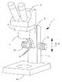
図1は、本発明の立体顕微鏡システム1の斜視図である。立体顕微鏡システム1は、焦点調節柱11を固定した台座13を有する。変位要素(調節ノブ)10によって両矢印A−Aに沿って移動可能な焦点調節アーム5は焦点調節柱11に摺動可能に取り付けられる。焦点調節アーム5は、立体顕微鏡3を支持する。立体顕微鏡3は、双眼筒(接眼部)9及び対物レンズグループ(図示無し)を有する。立体顕微鏡3は、焦点調節アーム5の受容開口に、焦点調節アーム5の対物レンズグループと共に固定される。複数の発光ダイオード31は、焦点調節柱11方向に向かって、焦点調節アーム5(の円弧状下面部)に設けられる。複数の発光ダイオード31は、立体顕微鏡システム1用の落射照明装置として機能する。 FIG. 1 is a perspective view of a stereoscopic microscope system 1 of the present invention. The stereoscopic microscope system 1 has a
図2は、本発明の立体顕微鏡システム1の側面図である。焦点調節アーム5に取り付けられる立体顕微鏡3は、両矢印A−Aに沿って移動することができる。移動は、少なくとも1つの変位要素10によって実行され、変位要素10は焦点調節柱11に配置される。立体顕微鏡3は、焦点調節アーム5にある立体顕微鏡の対物レンズグループと共に固定される。立体顕微鏡3は、立体顕微鏡システム1の台座13に対して垂直な装置軸(主光軸)20を規定する。図1の説明において述べたように、複数の発光ダイオード30、31は、焦点調節アーム5に設けられる。個々の発光ダイオード30、31は、個別に又はまとめて(もしくはグループ毎に)操作される。また、個々の発光ダイオード30、31は、個別に又はまとめて(もしくはグループ毎に)、その明るさを制御することができる。発光ダイオード30、31の明るさを制御する作動要素14は、焦点調節柱11に設けられる。別の作動要素15は、照明モードを調節するために、又は個々の発光ダイオードのグループ毎の操作を調節するために、焦点調節柱11に設けられる。焦点調節柱11への作動要素14、15の配置は、必須ではなく、該要素は、例えば、台座に配置してもよい。変位要素10によって、焦点調節アーム5(ないし立体顕微鏡3)は、両矢印A−Aに沿って変位することができる。立体顕微鏡3の変位は、装置軸20に平行に行われる。 FIG. 2 is a side view of the stereoscopic microscope system 1 of the present invention. The
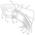
図3は、焦点調節アーム5を下から見た図である。焦点調節アーム5は、焦点調節柱11と協同(摺動可能に係合)する後端部5aを備える。また、焦点調節アーム5は、使用者に面する前端部(摺動受部)5bを備える。焦点調節アーム5の前端部5bは、顕微鏡観察が行われると共に立体顕微鏡を受容する開口5cを含めて構成される。また、立体顕微鏡3の装置軸20は、焦点調節アーム5の開口5cの中心を通って延在する。このため、発光ダイオード30の第1グループは、焦点調節アーム5の開口5c周りに配置される。発光ダイオード31の第2グループは、焦点調節アーム5の後端部5aの領域に配置される。本実施形態において、第1グループの発光ダイオード30は、開口5cに対して対称に配置される。しかしながら、これは、本発明を限定するものとして解釈されるものではない。台座13上の試料(図示なし)にとって最適な落射照明の実現に好適な態様で、開口5c周りに発光ダイオードを配置する可能性が多様であることは、当業者にとって明らかである。 FIG. 3 is a view of the
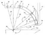
図4は、焦点調節アーム5の詳細図である。第1グループの発光ダイオード30及び第2グループの発光ダイオード31は、発光ダイオードの照明光軸25が立体顕微鏡システム1のおおよそ焦点28で台座13の上部で互いに交差するように、焦点調節アーム5上に配置される。第1グループの発光ダイオード30及び第2グループの発光ダイオード31は、個々の発光ダイオードの照明光軸25が試料平面13aに対して15°〜105°の角度範囲内にあるように、焦点調節アーム5に配置される。第2グループの少なくとも2つの発光ダイオード31は、カバー40を備える。カバー40は、主として、火傷から使用者を保護することに役立つ。焦点調節アーム5の高出力ダイオードは、かなり発熱するので、一方では、高出力の発光ダイオードの熱から使用者を保護する必要があり、他方では、汚染や損傷から高出力発光ダイオード自体を保護する必要がある。焦点調節アーム5自体は、発光ダイオード30の第1グループ及び発光ダイオード31の第2グループ用のヒートシンク又は冷却要素として具態化される。発光ダイオード用のカバー40は、付加的に、フィルタ特性を備えることもできるので、発光ダイオードの光は、別々に(異なるように)又は一様にフィルタすることもできる。フィルタ特性は、例えば、個別のカラーフィルタ41としてカバー40に組み込むことができる。また、フィルタ41をカバー40上に接着剤で接合することも考えられる。カバー40は、付加的に、交換可能なスライダとして具態化することもできる。使用者は、発光ダイオードの前に、様々なスペクトル照明条件に対応するスライダ又はカバーを配設することができる。 FIG. 4 is a detailed view of the
図5は、第1グループとして、発光ダイオード30を2つだけ有する本発明の焦点調節アーム5を下から見た斜視図である。焦点調節アーム5は、第1グループの発光ダイオード30及び第2グループの発光ダイオード31をはめ込む複数の凹部50を含めて構成される。第1グループの発光ダイオード30用の凹部50は、焦点調節アーム5に矩形状に構成される。焦点調節アーム5の後端部5a方向に向かって配置される第2グループの発光ダイオード31も凹部50に配置され、凹部50はU字状断面を含めて形成される。図4の説明において述べたように、U字状凹部52は、使用者が高出力発光ダイオードで火傷しないようにカバー40を備えることができる。U字状凹部52は、例えば、カバー40を保持するL字状のリム54を備える。カバー40がスライダとして形成される場合、U字状凹部のL字状リム54はスライダのガイドとして機能する。 FIG. 5 is a perspective view of the focusing
図4から明らかなように、発光ダイオード30の第1グループは、発光ダイオード30によって試料平面13a上の縦方向照明が可能となるように、焦点調節アーム5に設けられる。このため、第1グループの発光ダイオード30は、焦点調節アーム5の開口5cの近くに配置される。本発明において用語「縦方向照明(steile Beleuchtung, vertical illumination)」は、(試料平面13aに対して)発光ダイオードの照明光軸25が約75°〜105°の角度と規定される。発光ダイオード31の第2グループは、斜照明のために焦点調節アーム5に配置される。このため、発光ダイオード31は、焦点調節アーム5の後端部5aの近傍に取り付けられる。試料平面13aの最も近くに取り付けられる第2グループの発光ダイオード31は、中心28を有する試料視野の傾斜照明を提供する。図2の説明において述べたように、種々の照明モードを設定することができる作動要素15は、焦点調節柱11に設けられる。種々の発光ダイオード30、31は、様々な照明モードを設定できるようにそれに応じて作動することができる。これらの様々な照明モードのために、個々の発光ダイオードを機械的に変位させる必要はない。また、個々の照明モードは、互いに組み合わせることもできる。 As is clear from FIG. 4, the first group of light emitting
1 立体顕微鏡システム
3 立体顕微鏡
5 焦点調節アーム
5a 後端部
5b 前端部
5c 開口
9 双眼筒(接眼鏡筒)
10 変位要素
11 焦点調節柱
13 台座
13a 試料平面
14 作動要素
15 作動要素
20 装置軸
25 照明軸
28 中心(焦点)
30 発光ダイオード
31 発光ダイオード
40 カバー
41 フィルタ
50 凹部
52 U字状凹部
54 リム
DESCRIPTION OF SYMBOLS 1
DESCRIPTION OF
30 Light-emitting
Claims (14)
Translated fromJapanese前記焦点調節柱(11)に移動可能に取り付けられると共に、前記台座(13)に対して垂直な装置軸(20)を規定する立体顕微鏡(3)を支持する受容開口(5c)と、円弧状下面部とを備えた焦点調節アーム(5)、を有し、
点光源として複数の第1発光ダイオード(30)が、前記焦点調節アーム(5)の前記受容開口(5c)周りに配置されていると共に、縦方向落射照明に利用可能であり、
点光源として複数の第2発光ダイオード(31)が、前記焦点調節アーム(5)の前記円弧状下面部において、前記焦点調節柱(11)方向に向かって前記焦点調節アーム(5)に沿って上下に配置されていると共に、斜照明に利用可能であり、
前記複数の第2発光ダイオードのうち、焦点調節アーム(5)に試料平面(13a)の近傍に固定された前記第2発光ダイオード(31)は、かすめ入射照明として機能することを特徴とする立体顕微鏡システム。A pedestal (13) to which a focus adjustment column (11) is fixed, and a solid body movably attached to the focus adjustment column (11) and defining a device axis (20) perpendicular to the pedestal (13). A focus adjustment arm (5) having a receiving opening (5c) for supporting the microscope(3)and an arcuate lower surface ,
A plurality of first light emitting diodes (30)as point light sources are disposed around the receiving opening (5c) of the focus adjustment arm (5)and can be used for vertical epi-illumination ,
A plurality of second light emitting diodes (31)as point light sources arearranged along the focus adjustment arm (5) toward the focus adjustment column (11)in the arc-shaped lower surface portion of the focus adjustment arm (5).It is arrangedup and down and can be used for oblique lighting,
Among the plurality of second light emitting diodes, the second light emitting diode (31) fixed to the focus adjustment arm (5) in the vicinity of the sample plane (13a) functions asa grazing incidence illumination. Microscope system.
前記焦点調節アーム(5)は、同時に、前記第1発光ダイオード(30)及び前記第2発光ダイオード(31)のヒートシンクとして機能することを特徴とする請求項1に記載の立体顕微鏡システム。The first light emitting diode (30) and the second light emitting diode (31) are high power diodes,
The stereoscopic microscope system according to claim 1, wherein the focus adjustment arm (5) functions as a heat sink for the first light emitting diode (30) and the second light emitting diode (31) at the same time.
前記複数の第1発光ダイオード(30)及び前記複数の第2発光ダイオード(31)は、複数の前記照明光軸(25)が立体顕微鏡(3)の焦点(28)近傍で前記台座(13)上で交差するように、前記焦点調節アーム(5)に配置されることを特徴とする請求項1又は2に記載の立体顕微鏡システム。Each light emitting diode of the plurality of first light emitting diodes (30) and the plurality of second light emitting diodes (31) defines an illumination optical axis (25), respectively.
The plurality of first light emitting diodes (30) and the plurality of second light emitting diodes (31) are configured such that the plurality of illumination optical axes (25) are near the focal point (28) of the stereoscopic microscope (3) and the pedestal (13). The stereomicroscope system according to claim 1 or 2, wherein the stereomicroscope system is arranged on the focus adjustment arm (5) so as to intersect with each other.
前記複数の第1発光ダイオード(30)及び前記複数の第2発光ダイオード(31)の明るさは、個別に又はまとめて制御可能であることを特徴とする請求項1、2又は3に記載の立体顕微鏡システム。The plurality of first light emitting diodes (30) and the plurality of second light emitting diodes (31) can be operated individually or collectively,
4. The brightness of the plurality of first light emitting diodes (30) and the plurality of second light emitting diodes (31) can be individually or collectively controlled. 5. Stereo microscope system.
前記種々の角度は、15°〜105°の角度範囲を包含することを特徴とする請求項1〜4のいずれか一項に記載の立体顕微鏡システム。The plurality of first light emitting diodes (30) and the plurality of second light emitting diodes (31) are disposed on the focus adjustment arm (5) at various angles with respect to the sample plane (13a),
The stereoscopic microscope system according to claim 1, wherein the various angles include an angle range of 15 ° to 105 °.
前記複数の第2発光ダイオードの光は、別々に又は一様にフィルタされることを特徴とする請求項8に記載の立体顕微鏡システム。The cover (40) has filter characteristics;
The stereoscopic microscope system according to claim8 , wherein light from the plurality of second light emitting diodes is filtered separately or uniformly.
Applications Claiming Priority (2)
| Application Number | Priority Date | Filing Date | Title |
|---|---|---|---|
| DE102005036230ADE102005036230B3 (en) | 2005-08-02 | 2005-08-02 | Stereo microscope system with top lighting device has several light emitting diodes arranged in focusing arm around opening and several light emitting diodes arranged along arm in direction of focusing column |
| DE102005036230.3 | 2005-08-02 |
Publications (2)
| Publication Number | Publication Date |
|---|---|
| JP2007041596A JP2007041596A (en) | 2007-02-15 |
| JP5165867B2true JP5165867B2 (en) | 2013-03-21 |
Family
ID=37311345
Family Applications (1)
| Application Number | Title | Priority Date | Filing Date |
|---|---|---|---|
| JP2006208087AActiveJP5165867B2 (en) | 2005-08-02 | 2006-07-31 | Stereoscopic microscope system with epi-illumination device |
Country Status (4)
| Country | Link |
|---|---|
| US (1) | US7586677B2 (en) |
| JP (1) | JP5165867B2 (en) |
| CN (1) | CN1908721B (en) |
| DE (1) | DE102005036230B3 (en) |
Families Citing this family (12)
| Publication number | Priority date | Publication date | Assignee | Title |
|---|---|---|---|---|
| DE102005054184B4 (en) | 2005-11-14 | 2020-10-29 | Carl Zeiss Microscopy Gmbh | Multispectral lighting device and measuring method |
| DE102007006584B3 (en)* | 2007-02-09 | 2008-06-19 | Leica Microsystems (Schweiz) Ag | Illumination device for microscope, particularly trans-illumination device for stereo microscope, comprises carrier element on which point light sources are arranged and holder, which is provided for receiving each of point light sources |
| JP2009003186A (en)* | 2007-06-21 | 2009-01-08 | Olympus Corp | Luminaire |
| JP2009086079A (en)* | 2007-09-28 | 2009-04-23 | Nikon Corp | Microscope mount and microscope |
| AT506565B1 (en)* | 2008-04-09 | 2010-03-15 | Photonic Optische Geraete Gmbh | MICROSCOPE STAND |
| DE102010025114B4 (en)* | 2009-07-23 | 2014-08-07 | Leica Instruments (Singapore) Pte. Ltd. | Microscope with a microscope body and a tripod made of several components to fulfill a carrying function or a positioning of the microscope in space |
| EP2309303A1 (en) | 2009-10-05 | 2011-04-13 | Photonic Optische Geräte Ges.m.b.H. & Co.KG | Microscope |
| US20110080638A1 (en)* | 2009-10-06 | 2011-04-07 | Dieter Feger | Microscope |
| DE102013006995A1 (en)* | 2013-04-19 | 2014-10-23 | Carl Zeiss Microscopy Gmbh | Ring illumination device for a microscope objective and microscope objective |
| CN103616762A (en)* | 2013-12-09 | 2014-03-05 | 张波 | 3D intelligent digital microscope |
| ES2599056B2 (en)* | 2015-07-31 | 2017-07-07 | Pablo ALBERTOS SÁNCHEZ | Device for testing a sample of cells |
| CN108956466A (en)* | 2018-07-31 | 2018-12-07 | 江西省长益光电有限公司 | A kind of appearance inspection device |
Family Cites Families (15)
| Publication number | Priority date | Publication date | Assignee | Title |
|---|---|---|---|---|
| US2208882A (en)* | 1939-03-22 | 1940-07-23 | Paper Chemistry Inst | Microscope |
| US3798435A (en)* | 1973-08-09 | 1974-03-19 | Reichert Optische Werke Ag | Versatile light source for a microscope |
| JPH07122694B2 (en)* | 1986-10-16 | 1995-12-25 | オリンパス光学工業株式会社 | Illumination device for microscope |
| DE8915535U1 (en) | 1989-03-02 | 1990-10-25 | Carl Zeiss, 89518 Heidenheim | Incident light object lighting device |
| US5690417A (en)* | 1996-05-13 | 1997-11-25 | Optical Gaging Products, Inc. | Surface illuminator with means for adjusting orientation and inclination of incident illumination |
| JP3315358B2 (en)* | 1997-12-02 | 2002-08-19 | 株式会社ミツトヨ | Lighting equipment for image processing and measuring machines |
| US5897195A (en)* | 1997-12-09 | 1999-04-27 | Optical Gaging, Products, Inc. | Oblique led illuminator device |
| DE29809759U1 (en)* | 1998-05-29 | 1998-08-13 | WaveLight Laser Technologie GmbH, 91058 Erlangen | Device for medical treatment with a light source |
| DE19845603C2 (en)* | 1998-10-05 | 2000-08-17 | Leica Microsystems | Illumination device for a microscope |
| JP2001125003A (en)* | 1999-10-26 | 2001-05-11 | Nikon Corp | microscope |
| DE10030772B4 (en)* | 2000-04-26 | 2004-03-18 | Cobra Electronic Gmbh | Incident light illumination in microscopes with a ring carrier oriented around the optical axis for receiving illuminants |
| ATE235704T1 (en)* | 2000-04-26 | 2003-04-15 | Cobra Electronic Gmbh | ARRANGEMENT AND METHOD FOR RING-SHAPED ILLUMINATION, IN PARTICULAR FOR REFLECTED LIGHT ILLUMINATION IN MICROSCOPES |
| JP2003185929A (en)* | 2001-12-13 | 2003-07-03 | Olympus Optical Co Ltd | Stereomicroscope |
| JP2005017905A (en)* | 2003-06-27 | 2005-01-20 | Olympus Corp | Stereomicroscope |
| US7409147B2 (en)* | 2004-01-30 | 2008-08-05 | Samsung Techwin Co., Ltd. | Video presenter with arch-type support |
- 2005
- 2005-08-02DEDE102005036230Apatent/DE102005036230B3/ennot_activeExpired - Lifetime
- 2006
- 2006-07-26USUS11/460,148patent/US7586677B2/enactiveActive
- 2006-07-31JPJP2006208087Apatent/JP5165867B2/enactiveActive
- 2006-08-02CNCN2006101086541Apatent/CN1908721B/enactiveActive
Also Published As
| Publication number | Publication date |
|---|---|
| CN1908721B (en) | 2010-06-16 |
| JP2007041596A (en) | 2007-02-15 |
| DE102005036230B3 (en) | 2006-11-23 |
| US7586677B2 (en) | 2009-09-08 |
| CN1908721A (en) | 2007-02-07 |
| US20070030564A1 (en) | 2007-02-08 |
Similar Documents
| Publication | Publication Date | Title |
|---|---|---|
| JP5165867B2 (en) | Stereoscopic microscope system with epi-illumination device | |
| US8331020B2 (en) | Illumination device for a microscope | |
| US20050195601A1 (en) | Operating table lamp | |
| JP3943154B2 (en) | Stereomicroscope illumination means | |
| EP1780574B1 (en) | Microscope systeme with an illuminatig unit | |
| US20020109912A1 (en) | Lighting system for a stereomicroscope | |
| JP2010518435A5 (en) | ||
| EP1769733A3 (en) | Ophthalmic microscope | |
| JP2008043771A (en) | Attachment module for fundus examination and operation microscope with it | |
| JP2003185929A5 (en) | ||
| CN204462528U (en) | Lighting device and stereomicroscope | |
| JP2023060838A (en) | otoscope | |
| US20040066553A1 (en) | Portable microscope having an illumination device, and microscope stage | |
| JP4579554B2 (en) | Microscope illumination system | |
| US8243365B2 (en) | Microscope | |
| US7463414B2 (en) | Microscope | |
| JP2006296516A (en) | Bright-field light source for fluorescence observation and surgical microscope loaded with the same | |
| JP5094950B2 (en) | Microscope transmitted illumination device | |
| US10281699B2 (en) | Microscope system configured to irradiate focused light onto an area of a specimen outside of an optical axis of an objective lens | |
| CN201547526U (en) | Medical operation enlarging lens lamp | |
| JP2011118069A (en) | Microscope illumination device and microscope | |
| JP6760303B2 (en) | Shading device, microscope, and observation method | |
| CN210666182U (en) | External lighting device and operating microscope | |
| JP2011237549A (en) | Light source unit for microscope lighting device and microscope provided therewith | |
| JP2004151351A (en) | Transmissive illumination apparatus for stereomicroscope, and stereomicroscope |
Legal Events
| Date | Code | Title | Description |
|---|---|---|---|
| A621 | Written request for application examination | Free format text:JAPANESE INTERMEDIATE CODE: A621 Effective date:20090526 | |
| A711 | Notification of change in applicant | Free format text:JAPANESE INTERMEDIATE CODE: A711 Effective date:20100301 | |
| A131 | Notification of reasons for refusal | Free format text:JAPANESE INTERMEDIATE CODE: A131 Effective date:20111018 | |
| A601 | Written request for extension of time | Free format text:JAPANESE INTERMEDIATE CODE: A601 Effective date:20120113 | |
| A602 | Written permission of extension of time | Free format text:JAPANESE INTERMEDIATE CODE: A602 Effective date:20120118 | |
| A601 | Written request for extension of time | Free format text:JAPANESE INTERMEDIATE CODE: A601 Effective date:20120213 | |
| A602 | Written permission of extension of time | Free format text:JAPANESE INTERMEDIATE CODE: A602 Effective date:20120216 | |
| A601 | Written request for extension of time | Free format text:JAPANESE INTERMEDIATE CODE: A601 Effective date:20120313 | |
| A602 | Written permission of extension of time | Free format text:JAPANESE INTERMEDIATE CODE: A602 Effective date:20120316 | |
| A521 | Request for written amendment filed | Free format text:JAPANESE INTERMEDIATE CODE: A523 Effective date:20120412 | |
| A02 | Decision of refusal | Free format text:JAPANESE INTERMEDIATE CODE: A02 Effective date:20120619 | |
| A521 | Request for written amendment filed | Free format text:JAPANESE INTERMEDIATE CODE: A523 Effective date:20121017 | |
| A911 | Transfer to examiner for re-examination before appeal (zenchi) | Free format text:JAPANESE INTERMEDIATE CODE: A911 Effective date:20121024 | |
| TRDD | Decision of grant or rejection written | ||
| A01 | Written decision to grant a patent or to grant a registration (utility model) | Free format text:JAPANESE INTERMEDIATE CODE: A01 Effective date:20121127 | |
| A61 | First payment of annual fees (during grant procedure) | Free format text:JAPANESE INTERMEDIATE CODE: A61 Effective date:20121220 | |
| FPAY | Renewal fee payment (event date is renewal date of database) | Free format text:PAYMENT UNTIL: 20151228 Year of fee payment:3 | |
| R150 | Certificate of patent or registration of utility model | Ref document number:5165867 Country of ref document:JP Free format text:JAPANESE INTERMEDIATE CODE: R150 Free format text:JAPANESE INTERMEDIATE CODE: R150 | |
| R250 | Receipt of annual fees | Free format text:JAPANESE INTERMEDIATE CODE: R250 | |
| R250 | Receipt of annual fees | Free format text:JAPANESE INTERMEDIATE CODE: R250 | |
| R250 | Receipt of annual fees | Free format text:JAPANESE INTERMEDIATE CODE: R250 | |
| R250 | Receipt of annual fees | Free format text:JAPANESE INTERMEDIATE CODE: R250 | |
| R250 | Receipt of annual fees | Free format text:JAPANESE INTERMEDIATE CODE: R250 | |
| R250 | Receipt of annual fees | Free format text:JAPANESE INTERMEDIATE CODE: R250 | |
| R250 | Receipt of annual fees | Free format text:JAPANESE INTERMEDIATE CODE: R250 | |
| R250 | Receipt of annual fees | Free format text:JAPANESE INTERMEDIATE CODE: R250 | |
| R250 | Receipt of annual fees | Free format text:JAPANESE INTERMEDIATE CODE: R250 | |
| R250 | Receipt of annual fees | Free format text:JAPANESE INTERMEDIATE CODE: R250 |