JP5165062B2 - Piezoelectric module, internal combustion engine and glow plug - Google Patents
Piezoelectric module, internal combustion engine and glow plugDownload PDFInfo
- Publication number
- JP5165062B2 JP5165062B2JP2010522733AJP2010522733AJP5165062B2JP 5165062 B2JP5165062 B2JP 5165062B2JP 2010522733 AJP2010522733 AJP 2010522733AJP 2010522733 AJP2010522733 AJP 2010522733AJP 5165062 B2JP5165062 B2JP 5165062B2
- Authority
- JP
- Japan
- Prior art keywords
- piezoelectric
- piezoelectric element
- inner cylinder
- pressure
- piezoelectric module
- Prior art date
- Legal status (The legal status is an assumption and is not a legal conclusion. Google has not performed a legal analysis and makes no representation as to the accuracy of the status listed.)
- Expired - Fee Related
Links
Images


Classifications
- G—PHYSICS
- G01—MEASURING; TESTING
- G01L—MEASURING FORCE, STRESS, TORQUE, WORK, MECHANICAL POWER, MECHANICAL EFFICIENCY, OR FLUID PRESSURE
- G01L23/00—Devices or apparatus for measuring or indicating or recording rapid changes, such as oscillations, in the pressure of steam, gas, or liquid; Indicators for determining work or energy of steam, internal-combustion, or other fluid-pressure engines from the condition of the working fluid
- G01L23/22—Devices or apparatus for measuring or indicating or recording rapid changes, such as oscillations, in the pressure of steam, gas, or liquid; Indicators for determining work or energy of steam, internal-combustion, or other fluid-pressure engines from the condition of the working fluid for detecting or indicating knocks in internal-combustion engines; Units comprising pressure-sensitive members combined with ignitors for firing internal-combustion engines
- G01L23/221—Devices or apparatus for measuring or indicating or recording rapid changes, such as oscillations, in the pressure of steam, gas, or liquid; Indicators for determining work or energy of steam, internal-combustion, or other fluid-pressure engines from the condition of the working fluid for detecting or indicating knocks in internal-combustion engines; Units comprising pressure-sensitive members combined with ignitors for firing internal-combustion engines for detecting or indicating knocks in internal combustion engines
- G01L23/222—Devices or apparatus for measuring or indicating or recording rapid changes, such as oscillations, in the pressure of steam, gas, or liquid; Indicators for determining work or energy of steam, internal-combustion, or other fluid-pressure engines from the condition of the working fluid for detecting or indicating knocks in internal-combustion engines; Units comprising pressure-sensitive members combined with ignitors for firing internal-combustion engines for detecting or indicating knocks in internal combustion engines using piezoelectric devices
- F—MECHANICAL ENGINEERING; LIGHTING; HEATING; WEAPONS; BLASTING
- F23—COMBUSTION APPARATUS; COMBUSTION PROCESSES
- F23Q—IGNITION; EXTINGUISHING-DEVICES
- F23Q7/00—Incandescent ignition; Igniters using electrically-produced heat, e.g. lighters for cigarettes; Electrically-heated glowing plugs
- F23Q7/001—Glowing plugs for internal-combustion engines
- F23Q2007/002—Glowing plugs for internal-combustion engines with sensing means
Landscapes
- Chemical & Material Sciences (AREA)
- Engineering & Computer Science (AREA)
- Combustion & Propulsion (AREA)
- Physics & Mathematics (AREA)
- General Physics & Mathematics (AREA)
- Measuring Fluid Pressure (AREA)
Description
Translated fromJapanese本発明は、変位や振動を発生する圧電アクチュエータ、気体、液体等の圧力を測定するための圧電センサ、さらには自動車用エンジンの燃焼圧力を測定するための圧電センサ等の圧電モジュールに関する。 The present invention relates to a piezoelectric module such as a piezoelectric actuator for generating displacement or vibration, a piezoelectric sensor for measuring pressure of gas, liquid, etc., and a piezoelectric sensor for measuring combustion pressure of an automobile engine.
従来から圧電アクチュエータや圧電センサの用途で圧電素子が用いられている。例えば特許文献1には、圧電素子を搭載した圧力センサが開示されている。 Conventionally, piezoelectric elements have been used for piezoelectric actuators and piezoelectric sensors. For example,
この圧力センサは、受圧面を有し、側壁の一部に他の部分より熱膨張率の大きい部分を有する筺体と、筺体の内部に設けられ、かつ一端が受圧面の裏側の面に接する圧力伝達部材と、筺体の内部に設けられ、かつ圧力伝達部材の他端に設けられた圧電素子を有し、筺体の加熱時に熱膨張率の大きい部分が他の部分よりも大きく延びることによって圧電素子と受圧面との位置関係の変化を規制するものである。 This pressure sensor has a pressure receiving surface, a housing having a portion having a larger coefficient of thermal expansion than other portions on a part of the side wall, and a pressure that is provided inside the housing and has one end in contact with the back surface of the pressure receiving surface. A piezoelectric element having a transmission member and a piezoelectric element provided inside the housing and provided at the other end of the pressure transmission member, and a portion having a larger coefficient of thermal expansion when heated than the other portion when the housing is heated The change in the positional relationship between the pressure receiving surface and the pressure receiving surface is regulated.
この構成により、センサの筺体の側壁部の一部に他の部分より熱膨張率の大きい部分を設け、この部分が熱膨張することで筺体の先端の受圧面を圧電素子側へ引き寄せる構造とすることができる。その結果、熱膨張による予備圧力変動を防止できるので、温度特性に優れた圧電型圧力センサを実現できる。 With this configuration, a part having a larger coefficient of thermal expansion than the other part is provided in a part of the side wall part of the sensor casing, and this part is thermally expanded to draw the pressure receiving surface at the front end of the casing toward the piezoelectric element side. be able to. As a result, the preliminary pressure fluctuation due to thermal expansion can be prevented, so that a piezoelectric pressure sensor having excellent temperature characteristics can be realized.
また、特許文献1の圧力センサは、上記の圧電素子を有し、筺体の加熱時に熱膨張率の小さい部分の延びが小さいことによる圧電素子と受圧面との位置関係の変化を規制するものである。 Moreover, the pressure sensor of
この構成により、センサ筺体側壁部の一部に圧電素子や圧力伝達部材より熱膨張率の小さい部分を設け、センサ筺体全体の熱膨張を圧電素子と圧力伝達部材を合わせた熱膨張と等しくすることができる。その結果、熱膨張による予備圧力変動を防止できるので、温度特性に優れた圧電型圧力センサを実現できる。 With this configuration, a part having a smaller thermal expansion coefficient than that of the piezoelectric element or the pressure transmission member is provided in a part of the side wall portion of the sensor casing, and the thermal expansion of the entire sensor casing is equal to the thermal expansion of the piezoelectric element and the pressure transmission member. Can do. As a result, the preliminary pressure fluctuation due to thermal expansion can be prevented, so that a piezoelectric pressure sensor having excellent temperature characteristics can be realized.
しかしながら、特許文献1に記載された圧力センサの場合は、熱膨張による影響を小さくすることを目的としており、数kHz〜数10kHz程度の高周波数の圧力振動が加わった際の応答性を向上させること、また耐久性を向上させて信頼性を高めること等については記載されていない。 However, in the case of the pressure sensor described in
例えば、自動車等の内燃機関に設けられる燃焼圧センサとして圧力センサを用いる場合には、圧力センサには数kHz〜数10kHz程度の高周波数および高圧力の圧力振動が加わるため、高い応答性と優れた耐久性が要求される。 For example, when a pressure sensor is used as a combustion pressure sensor provided in an internal combustion engine such as an automobile, the pressure sensor is subjected to high frequency and high pressure pressure vibration of about several kHz to several tens of kHz, so that high responsiveness and excellent Durability is required.
本発明は上記従来の問題点に鑑みて完成されたものであり、その目的は、高い応答性を有し、また優れた耐久性を有する圧電モジュールを提供すること、さらにその圧電モジュールを用いた内燃機関およびグロープラグを提供することにある。 The present invention has been completed in view of the above-described conventional problems, and an object thereof is to provide a piezoelectric module having high responsiveness and excellent durability, and further using the piezoelectric module. It is to provide an internal combustion engine and a glow plug.
本発明の圧電モジュールは、先頭ピンと、該先頭ピンの後端面側に第1の面が位置するように設けられた圧電素子と、該圧電素子の前記第1の面に対向する第2の面を先端が押圧する棒状の差込具とを具備し、装置の取付け孔に挿置される圧電モジュールであって、前記差込具の先端部に一端が固定されるとともに他端が前記取付け孔の壁面の段差に係止されて前記圧電素子および前記先頭ピンの後端部を覆う外筒と、該外筒の内側に設置された、前記先頭ピンから前記圧電素子に伝わる圧力を弾性変形して緩和する内筒とを有しており、該内筒は、前記差込具の一部として一体化されて形成されていることを特徴とするものである。
The piezoelectric module of the present invention includes a leading pin, a piezoelectric element provided so that the first surface is located on the rear end surface side of the leading pin, and a second surface facing the first surface of the piezoelectric element. A piezoelectric module that is inserted into a mounting hole of the device, and has one end fixed to the distal end portion of the insertion tool and the other end of the mounting hole. An outer cylinder that is locked to a step of the wall surface of the piezoelectric element and covers a rear end portion of the piezoelectric element and the leading pin, and elastically deforms pressure transmitted from the leading pin to the piezoelectric element that is installed inside the outer cylinder. Theinner cylinder is formed integrally as a part of the insertion tool .
また、本発明の圧電モジュールは好ましくは、前記圧電素子は、前記内筒の内側に配置されていることを特徴とするものである。 The piezoelectric module of the present invention is preferably characterized in that the piezoelectric element is arranged inside the inner cylinder.
また、本発明の圧電モジュールは好ましくは、前記内筒は、内面と外面との間の厚みが1mm以下であることを特徴とするものである。 The piezoelectric module of the present invention is preferably characterized in that the inner cylinder has a thickness of 1 mm or less between the inner surface and the outer surface.
また、本発明の圧電モジュールは好ましくは、前記内筒は、長さが3mm以上であることを特徴とするものである。 In the piezoelectric module of the present invention, preferably, the inner cylinder has a length of 3 mm or more.
また、本発明の圧電モジュールは好ましくは、前記外筒は、前記差込具の先端部に固定される前記一端が前記圧電素子よりも前記先頭ピンから離れる側に位置していることを特徴とするものである。 In the piezoelectric module of the present invention, preferably, the outer cylinder has the one end fixed to the distal end portion of the insertion tool positioned on a side farther from the leading pin than the piezoelectric element. To do.
本発明の内燃機関は、上記いずれかの本発明の圧電モジュールを搭載したことを特徴とするものである。 An internal combustion engine of the present invention is characterized by mounting any one of the above-described piezoelectric modules of the present invention.
本発明のグロープラグは、上記いずれかの本発明の圧電モジュールを設けたことを特徴とするものである。 The glow plug of the present invention is characterized in that any one of the above-described piezoelectric modules of the present invention is provided.
本発明の圧電モジュールは、先頭ピンと、先頭ピンの後端面側に第1の面が位置するように設けられた圧電素子と、圧電素子の第1の面に対向する第2の面を先端が押圧する棒状の差込具とを具備し、装置の取付け孔に挿置される圧電モジュールであって、差込具の先端部に一端が固定されるとともに他端が取付け孔の壁面の段差に係止されて圧電素子および先頭ピンの後端部を覆う外筒と、外筒の内側に設置された、先頭ピンから圧電素子に伝わる力を弾性変形して緩和する内筒とを有しており、該内筒は、差込具の一部として一体化されて形成されていることから、例えば圧力センサとして使用した場合に、圧力を発生する内燃機関等の装置に圧電モジュールを設置する際に、例えば装置の取付け孔(ねじ孔)に圧電モジュールの棒状の差込具をねじ込んで設置するが、ねじ込みによる締結力を外筒が受け持ち、その締結力は圧電素子には直接加わらない。また、外筒と独立した、力を弾性変形して緩和する内筒が、力を圧電素子に伝達する。従って、締結力と測定すべき力とが分離され、締結力による力信号オフセットの発生がなくなり、力を直接的に測定することができる。その結果、力に対する高い応答性を実現できる。また、内筒が差込具の一部として一体化されて形成されていることから、円形状である内筒の端面が、差込具の先端部に一様に接した状態となり、先頭ピンで受けた応力は、一様に緩和されることとなる。従って、圧電素子が測定すべき圧力は、ある一部分に偏ることなく、先頭ピンから圧電素子に伝達されるため、本発明の圧電モジュールの測定精度を向上させることができる。
The piezoelectric module of the present invention has a leading pin, a piezoelectric element provided so that the first surface is positioned on the rear end surface side of the leading pin, and a second surface facing the first surface of the piezoelectric element at the tip. A piezoelectric module that is inserted into the mounting hole of the apparatus, and has one end fixed to the tip of the insertion tool and the other end being a step on the wall surface of the mounting hole. An outer cylinder that is locked and covers the piezoelectric element and the rear end portion of the leading pin, and an inner cylinder that is installed inside the outer cylinder and elastically deforms and relaxes the force transmitted from the leading pin to the piezoelectric element.Since the inner cylinder is integrally formed as a part of the insertion tool , for example, when used as a pressure sensor, when the piezoelectric module is installed in a device such as an internal combustion engine that generates pressure. In addition, for example, the mounting hole (screw hole) of the device has a rod-shaped piezoelectric module Installing by screwing write device, but the outer cylinder is responsible for the fastening force by screwing, the fastening force to the piezoelectric element is not directly applied. Further, an inner cylinder that is elastically deformed and relaxed independently of the outer cylinder transmits the force to the piezoelectric element. Therefore, the fastening force and the force to be measured are separated, the generation of a force signal offset due to the fastening force is eliminated, and the force can be measured directly. As a result, high responsiveness to force can be realized.In addition, since the inner cylinder is integrally formed as a part of the insertion tool, the end surface of the circular inner cylinder is in a state of being in uniform contact with the distal end portion of the insertion tool, and the leading pin The stress received in is uniformly relaxed. Therefore, since the pressure to be measured by the piezoelectric element is transmitted from the leading pin to the piezoelectric element without being biased to a certain part, the measurement accuracy of the piezoelectric module of the present invention can be improved.
また、圧電素子は、圧力測定対象の装置への締結力が直接加わらないため、装置の振動による力信号の変動の発生を抑制でき、その点でも高い応答性を実現できる。 In addition, since the fastening force to the device whose pressure is to be measured is not directly applied to the piezoelectric element, the fluctuation of the force signal due to the vibration of the device can be suppressed, and high responsiveness can also be realized in that respect.
また、圧電素子に加わる力(圧力に基づく力)は、内筒が弾性変形して緩和されるために、圧電素子の破損等が抑制され、圧電モジュールの耐久性が向上する。 Further, the force (force based on pressure) applied to the piezoelectric element is relaxed by elastic deformation of the inner cylinder, so that damage to the piezoelectric element is suppressed, and the durability of the piezoelectric module is improved.
また、本発明の圧電モジュールは好ましくは、圧電素子は、内筒の内側に配置されていることから、圧電素子を力を緩和する内筒の内側に密閉して格納することができ、圧電素子に対する力の影響をより小さくでき、圧電素子の耐久性を向上させることができる。 In the piezoelectric module of the present invention, preferably, since the piezoelectric element is disposed inside the inner cylinder, the piezoelectric element can be sealed and stored inside the inner cylinder for relaxing the force. The influence of the force on can be made smaller, and the durability of the piezoelectric element can be improved.
また、本発明の圧電モジュールは好ましくは、内筒は、内面と外面との間の厚みが1mm以下であることから、内筒が薄型化されて弾性変形に適したものとなる。その結果、圧電素子に加わる圧力を内筒が緩和する効果が向上する。 In the piezoelectric module of the present invention, the inner cylinder preferably has a thickness of 1 mm or less between the inner surface and the outer surface, so that the inner cylinder is thinned and suitable for elastic deformation. As a result, the effect of the inner cylinder relaxing the pressure applied to the piezoelectric element is improved.
また、本発明の圧電モジュールは好ましくは、内筒は、長さが3mm以上であることから、内筒の弾性変形による変形長さが長くなり、弾性変形に適したものとなる。その結果、圧電素子に加わる力を内筒が緩和する効果が向上する。 In the piezoelectric module of the present invention, preferably, the inner cylinder has a length of 3 mm or more, so that the deformation length due to the elastic deformation of the inner cylinder becomes long and is suitable for elastic deformation. As a result, the effect that the inner cylinder relaxes the force applied to the piezoelectric element is improved.
また、本発明の圧電モジュールは好ましくは、外筒は、差込具の先端部に固定される一端が圧電素子よりも圧力室から離れる側に位置していることから、棒状の差込具のねじ込みによる締結力を、測定すべき力からより分離させることができる。その結果、力に対するより高い応答性を実現できる。 In the piezoelectric module of the present invention, preferably, the outer cylinder has one end fixed to the distal end portion of the insertion tool positioned on the side farther from the pressure chamber than the piezoelectric element. The fastening force due to screwing can be further separated from the force to be measured. As a result, higher responsiveness to force can be realized.
本発明の内燃機関は、上記本発明の圧電モジュールを燃焼圧センサとして搭載したことから、高い応答性と優れた耐久性とを有する圧電モジュールを用いているため、内燃機関の燃焼特性の制御性が高まり、また耐久性が向上する。 Since the internal combustion engine of the present invention is equipped with the piezoelectric module of the present invention as a combustion pressure sensor, the piezoelectric module having high responsiveness and excellent durability is used. And durability is improved.
本発明のグロープラグは、上記本発明の圧電モジュールを設けたことから、高い応答性と優れた耐久性とを有する圧電モジュールを用いているため、グロープラグの内燃機関の気筒(シリンダー)内の温度の制御性が高まり、また耐久性が向上する。 Since the glow plug of the present invention is provided with the piezoelectric module of the present invention, a piezoelectric module having high responsiveness and excellent durability is used. Therefore, the glow plug in the cylinder of the internal combustion engine of the glow plug is used. Temperature controllability is increased and durability is improved.
本発明の圧電モジュールの実施の形態について以下に詳細に説明する。 Embodiments of the piezoelectric module of the present invention will be described in detail below.
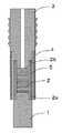
図1は、本例の圧電モジュールの実施の形態の一例を示す断面図である。図1において、1は圧力を受ける先頭ピン(受圧ピン)、2は圧電素子、2aは圧電素子2の第1の面、2bは圧電素子2の第2の面、3は差込具(プラグ)、4は外筒、5は内筒、6は圧力を測定する対象である装置、例えば内燃機関の気筒(シリンダー)等の圧力が発生する圧力室、6aは圧力室6の貫通孔、6bは貫通孔6aの壁面の段差である。 FIG. 1 is a cross-sectional view showing an example of an embodiment of the piezoelectric module of this example. In FIG. 1, 1 is a leading pin (pressure receiving pin) for receiving pressure, 2 is a piezoelectric element, 2a is a first surface of the
本例の圧電モジュールは、先頭ピン1と、先頭ピン1の後端面側に第1の面2aが位置するように設けられた圧電素子2と、圧電素子2の第1の面2aに対向する第2の面2bを先端が押圧する棒状の差込具3とを具備し、圧力を測定する対象である装置としての圧力室6の取付け孔(貫通孔)6aに挿置される圧電モジュールであって、差込具3の先端部に一端が固定されるとともに他端が貫通孔6aの壁面の段差6bに係止されて圧電素子2および先頭ピン1の後端部を覆う外筒4と、外筒4の内側に設置された、先頭ピン1から圧電素子2に伝わる力を弾性変形して緩和する内筒5とを有している。 The piezoelectric module of this example is opposed to the
上記の構成により、圧力測定対象の装置の圧力室6に圧電モジュールを設置する際に、例えば圧力室6の貫通孔(ねじ孔)6aに圧電モジュールの棒状の差込具3をねじ込んで設置するが、ねじ込みによる締結力を外筒4が受け持ち、締結力は圧電素子2には直接加わらない。また、外筒4と独立した、力としての圧力を弾性変形して緩和する内筒5が、圧力を圧電素子2に伝達する。従って、締結力と測定すべき圧力とが分離され、締結力による圧力信号オフセットの発生がなくなり、圧力を直接的に測定することができる。その結果、圧力に対する高い応答性を実現できる。 With the above configuration, when the piezoelectric module is installed in the
また、圧電素子2は、圧力測定対象の装置への締結力が直接加わらないため、装置の振動による圧力信号の変動の発生を抑制でき、その点でも高い応答性を実現できる。 In addition, since the fastening force to the device whose pressure is to be measured is not directly applied to the
また、圧電素子2に加わる圧力は、内筒5が弾性変形して緩和するために、圧電素子2の破損等が抑制され、圧電モジュールの耐久性が向上する。 Moreover, since the
図1に示す例の構成において、内筒5は外筒4の内側に隙間を介して配置されている。この隙間は、内筒5が圧力によって弾性変形し易いようにする目的で設けられる。この隙間があることにより、内筒5と外筒4とが衝突することがなく、また圧電モジュールが大型化することがない。 In the configuration of the example shown in FIG. 1, the
先頭ピン1、差込具3、外筒4および内筒5は好ましくは、例えば高温(数100℃〜1000℃程度)となる自動車等のエンジンの燃焼室(気筒:シリンダー)内の圧力を測定する場合を想定して、耐熱性および耐食性の高いステンレススチール等の金属から成る。しかしながら、必ずしもステンレススチール等の金属に限定するものではなく、用途によっては樹脂,セラミックス等の材料を用いても良い。 The
また、本例の圧電モジュールは、全体の形状が円柱状、角柱状等の柱状である。従って、先頭ピン1、差込具3および圧電素子2は、全体的な形状が円柱状、角柱状等の柱状である。また、外筒4および内筒5は、全体的な形状が円筒状、角筒状等の筒状である。 In addition, the piezoelectric module of this example has a columnar shape such as a columnar shape or a prismatic shape as a whole. Therefore, the
圧電素子2は、例えば、チタン酸ジルコン酸鉛(PZT:Pb(Zrx,Ti1−x)O3)(xは0.525程度)等の圧電体と、それに設けられた一対の対向電極とを有する構成である。また、圧電素子2は、PZT等から成る圧電体層と銀等から成る電極層とを交互に多層に積層した多層積層構造のものであってもよい。また圧電素子2は、図1に示すように、例えば先頭ピン1と差込具3とに挟まれて内筒5の内側に配設される。The
本例の圧電モジュールは好ましくは、圧電素子2は、内筒5の内側に配置されている。この場合、圧電素子2を圧力を緩和する内筒5の内側に密閉して格納することができ、圧電素子2に対する圧力の影響をより小さくでき、圧電素子2の耐久性を向上させることができる。また、圧電素子2は、内筒5の内側の中央部に配置されることがより好ましく、この場合には圧電素子2の耐久性をより向上させることができる。すなわち、圧電素子2が内筒5の内側の中央部に配置されることによって、圧電素子2に加わる圧力が内筒5によって最も効果的に分散され緩和される位置に、圧電素子2が配置されることになる。 In the piezoelectric module of this example, the
また、本例の圧電モジュールは好ましくは、内筒5は、内面と外面との間の厚みが1mm以下である。この場合、内筒5が薄型化されて弾性変形に適したものとなる。その結果、圧電素子2に加わる力を内筒5が緩和する効果が向上する。内筒5における内面と外面との間の厚みの下限値は、0.2mm程度である。内面と外面との間の厚みが0.2mm未満では、内筒5が薄すぎるため、強度が低下し、圧力によって塑性変形したり破壊されたりし易くなる。また、内筒5の製造が容易でなくなる。 In the piezoelectric module of this example, preferably, the
また、本発明の圧電モジュールは好ましくは、内筒5は、長さが3mm以上である。この場合、内筒5の弾性変形による変形長さが長くなり、弾性変形に適したものとなる。その結果、圧電素子2に加わる圧力を内筒5が緩和する効果が向上する。内筒5の長さの上限値は、20mm程度である。内筒5の長さが20mmを超えると、内筒5の弾性変形による変形長さが長くなりすぎ、また強度が低下し、力によって塑性変形し易くなる。また、圧電モジュールが大型化する傾向がある。 In the piezoelectric module of the present invention, preferably, the
また、内筒5に代えてばねを用いたものであってもよい。この場合、ばねは筒形状のものと比較して大きく弾性変形することから、圧電素子2に加わる力を緩和する効果が向上する。なお、内筒5の一部をばねに代えてもよい。例えば、差込具3の先端部に固定される方の端部および先頭ピン1に固定される方の端部は筒形状の部材であり、両者の間の部分のみがばねで構成されるものを、内筒5に代えて使用してもよい。 Further, instead of the
また、内筒5は、差込具3の一部として、一体化されて形成されている。このことから、円形状である内筒5の端面が、差込具3の先端部に一様に接した状態となる。従って、
先頭ピン1で受けた応力は、一様に緩和されることとなる。従って、圧電素子2が測定すべき圧力は、ある一部分に偏ることなく、先頭ピン1から圧電素子2に伝達されるため、本発明の圧電モジュールの測定精度を向上させることができる。Further, the
The stress received by the leading
また、本発明の圧電モジュールは好ましくは、外筒4は、差込具3の先端部に固定される一端が圧電素子2よりも先頭ピン1から離れる側(圧電素子2に対して先頭ピン1と反対側)に位置している。この場合、棒状の差込具3の貫通孔6aへのねじ込みによる締結力を、測定すべき圧力からより確実に分離させることができる。その結果、圧力に対するより高い応答性を実現できる。例えば、外筒4における差込具3の先端部に固定される一端は、圧電素子2よりも0.5〜5mm程度先頭ピン1から離れる側に位置することが良い。この範囲内とすることにより、外筒4が長くなりすぎて、強度が低下し、圧力によって塑性変形し易くなることを抑制し、また、圧電モジュールが大型化することを抑えることができる。 Further, in the piezoelectric module of the present invention, preferably, the
圧電モジュールは、差込具3の雄ねじ部および貫通孔(ねじ孔)6aの雌ねじ部の接合部(ねじ接合部)で固定されているだけでなく、差込具3を貫通孔6aにねじ込み、差込具3が外筒4を壁面の段差6bに押し付けることによって、差込具3および外筒4がねじ接合部および、外筒4の端部と貫通孔6aの壁面の段差6bとの接触部の間で圧縮されることによって締結力が強められるので、より強固に固定されることとなる。 The piezoelectric module is not only fixed at the joint portion (screw joint portion) of the male screw portion of the
従って、外筒4を用いることによって、圧電モジュールを貫通孔6aに強固に固定することができる。また、外筒4は、前述した締結力を受け持ってはいるが、内筒5とは互いに独立していることから、内筒5には締結力の影響が及ばない。従って、圧電モジュールにおいて、締結力と測定すべき圧力とが分離されることにより、測定すべき圧力に対する高い応答性を実現できる。 Therefore, by using the
また、外筒4は、内筒5よりも剛性が高いことが好ましい。すなわち、外筒4は、棒状の差込具3の貫通孔6aへのねじ込みによる締結力が常時加わるものであることから、長期間の使用においても圧電素子2の位置ずれが発生しにくいように、内筒5よりも高い剛性を有していることが好適であるからである。 Further, the
また、差込具3の貫通孔6aへの固定に際しては、ねじ込みによる締結に限られるものではなく、半田等の接続材によるものであってもよい。例えば、差込具3の外径および貫通孔6aの内径の間に隙間ができる状態としておき、両者の間に溶融させた半田を流し込む方法が挙げられる。この場合は、差込具3を貫通孔6aに固定する際に生じる締結力が生じないため、圧電素子2における測定すべき圧力に対する応答性が向上するので好ましい。 Further, the fixing of the
また、本発明の圧電モジュールは好ましくは、外筒4は単数に限らず、同心円状に複数あってもよい。 The piezoelectric module of the present invention is preferably not limited to a single
また、外筒4は、差込具3の一部として、差込具3と一体化して形成されていてもよい。この場合には、円形状である外筒4の端面が、差込具3の先端部に一様に接した状態となる。従って、差込具3の貫通孔6aへのねじ込みによる締結力が偏りなく外筒4に印加される。従って、外筒4において締結力を均等に分散させることができるので、外筒4が部分的に破損や変形しにくくなるので、圧電素子2および先頭ピン1の位置ずれが起こりにくくなることより、先頭ピン1にかかる圧力を、長期にわたって高い精度で測定することができる。 Further, the
本発明の内燃機関は、上記本発明の圧電モジュールを燃焼圧センサとして搭載する構成である。このことから、高い応答性と優れた耐久性とを有する圧電モジュールを用いているため、内燃機関の燃焼特性の制御性が高まり、また耐久性が向上する。 The internal combustion engine of the present invention is configured to mount the piezoelectric module of the present invention as a combustion pressure sensor. Accordingly, since the piezoelectric module having high responsiveness and excellent durability is used, the controllability of the combustion characteristics of the internal combustion engine is enhanced and the durability is improved.
内燃機関は、例えば、気筒(シリンダー)、ピストン、点火プラグ、グロープラグ、燃料噴射装置、シリンダーに供給する燃料の弁(バルブ)開閉装置等の種々の周知の装置を有するものである。具体的には、自動車等の乗物、貨物運搬車両等に用いられるガソリンエンジン、アルコール混合ガソリンエンジン、ディーゼルエンジン、アルコールエンジン、水素ガスエンジン等である。 The internal combustion engine has various known devices such as a cylinder, a piston, a spark plug, a glow plug, a fuel injection device, and a valve opening / closing device for a fuel supplied to the cylinder. Specific examples include gasoline engines, alcohol-mixed gasoline engines, diesel engines, alcohol engines, hydrogen gas engines, and the like used for vehicles such as automobiles and cargo vehicles.
本発明の内燃機関に用いられる本発明の圧電モジュールは、圧力室6としての内燃機関の燃焼室(シリンダー)に設置され、燃料の燃焼爆発による圧力を受圧して圧力を測定する。 The piezoelectric module of the present invention used in the internal combustion engine of the present invention is installed in the combustion chamber (cylinder) of the internal combustion engine as the
本発明のグロープラグは、上記本発明の圧電モジュールを設けた構成である。このことから、高い応答性と優れた耐久性とを有する圧電モジュールを用いているため、グロープラグの内燃機関の気筒(シリンダー)内の温度の制御性が高まり、また耐久性が向上する。 The glow plug of the present invention has a configuration provided with the piezoelectric module of the present invention. Accordingly, since the piezoelectric module having high responsiveness and excellent durability is used, the controllability of the temperature in the cylinder of the internal combustion engine of the glow plug is enhanced, and the durability is improved.
グロープラグは、ディーゼルエンジンの気筒内の温度を制御する装置であり、例えば、気筒内の温度が低いとエンジンの始動が不調になるため、エンジンの始動前に気筒内に設けられたグロープラグを予熱して燃料着火を確実にし、始動性を高めるように作動する。従って、グローブラグは、ディーゼルエンジンの燃焼室内に先端を突出させて設けられる。 The glow plug is a device that controls the temperature in the cylinder of the diesel engine. For example, if the temperature in the cylinder is low, the engine starts malfunctioning. Therefore, the glow plug provided in the cylinder before starting the engine is used. Preheat to ensure fuel ignition and operate to improve startability. Therefore, the glove lug is provided with its tip projecting into the combustion chamber of the diesel engine.
このグロープラグは、例えば、抵抗変化率の大きい金属からなる通電用抵抗体と、通電用抵抗体の先端に接続され、固有抵抗が大きくかつ抵抗変化率の小さい金属からなる発熱用抵抗体と、これらの抵抗体を覆うシース管とを有する構成である。 The glow plug includes, for example, a current-carrying resistor made of a metal having a high resistance change rate, a heating resistor connected to the tip of the current-carrying resistor and having a large specific resistance and a low resistance change rate, and The sheath tube covers these resistors.
通電用抵抗体は、抵抗変化率の大きいFe,Ni等の金属からなり、発熱用抵抗体は、固有抵抗が大きくかつ抵抗変化率の小さいFeCr,NiCr等の金属からなる。 The energizing resistor is made of a metal such as Fe or Ni having a large resistance change rate, and the heating resistor is made of a metal such as FeCr or NiCr having a large specific resistance and a small resistance change rate.
図2〜図5は、本発明の圧電モジュールの製造方法の一例を示す工程ごとの断面図である。図2に示すように、まず始めに、先頭ピン1と内筒5とを予め接合して固定する。両者を接合する方法としては、ガス溶接、レーザ溶接、抵抗溶接、電子ビーム溶接等の溶接法を用いる。または、摩擦圧接、ロー付け、拡散接合等の接合方法を用いても良い。次に、内筒5の内側に圧電素子2を配置する。 2-5 is sectional drawing for every process which shows an example of the manufacturing method of the piezoelectric module of this invention. As shown in FIG. 2, first, the leading
次に、図3に示すように、先頭ピン1の後端面と差込具3の先端部とで圧電素子2が隙間無く挟まれるようにする。その後、内筒5の差込具3側の端と、差込具3の先端部の当接箇所とを接合して固定する。接合する方法としては、ガス溶接、レーザ溶接、抵抗溶接、電子ビーム溶接等の溶接法を用いる。または、摩擦圧接、ロー付け、拡散接合等の接合方法を用いる。このとき、内筒5と差込具3とが当接して接合される位置は、圧電素子2より圧力室6から離れる側に位置するように、内筒5の長さと差込具3の先端部の長さとを設定する。 Next, as shown in FIG. 3, the
次に、図4、図5に示すように、外筒4が、差込具3の先端部に一端が固定されるとともに他端が貫通孔6aの壁面の段差6bに係止されて圧電素子2および先頭ピン1の後端部を覆うように設置される。このとき、外筒4と差込具3とが当接して固定される位置は、内筒5と差込具3とが当接して固定される位置よりも先頭ピン1から離れる側に位置するように調整することが好ましい。この場合には、貫通孔6aへのねじ込みによる締結力を、測定すべき圧力から分離する効率がより高まるという効果がある。 Next, as shown in FIGS. 4 and 5, the
外筒4の一端と差込具3の先端部とを固定する方法は、ガス溶接、レーザ溶接、抵抗溶接、電子ビーム溶接等の溶接法を用いる。または、摩擦圧接、ロー付け、拡散接合等の接合方法を用いても良い。さらには、外筒4の一端と差込具3の先端部とを当接させるだけとし、外筒4の他端を係止することによって固定してもよい。 As a method of fixing one end of the
このようにして構成した圧電モジュールは、先頭ピン1が圧力室6に暴露されることによって圧力を受け、内筒5が弾性変形し、先頭ピン1と差込具3との間に挟まれた圧電素子2が圧力を感知して電気信号を発生させることによって、圧力を測定する。 The piezoelectric module configured as described above is subjected to pressure when the leading
外筒4は一端が差込具3に接合され固定されて、他端が貫通孔6aの段差部6bに係止される。このとき、圧電モジュールを貫通孔6aに差し込み、例えば差込具3の表面に形成されたねじ部を貫通孔6aの壁面のねじ部にねじ込んで固定する場合であれば、ねじ込みによって発生する軸方向の推力(締結力)を外筒4が受け持つ。またこのとき、内筒5、先頭ピン1および圧電素子2は、ねじ込みによって発生する軸方向の推力から分離されているため、推力の変動によって圧電素子2の出力が影響を受けることが無く、高い応答性を確保することができる。また、圧電素子2に推力が伝達しないことから、繊細な扱いが要求される圧電素子2に破損等を与えることが無く、耐久性が向上する。このような構成は、例えば、圧電モジュールの組み付け時や、メンテナンスのために取り外しおよび取り付けを行なう際などにも有効である。 One end of the
1:先頭ピン
2:圧電素子
2a:第1の面
2b:第2の面
3:差込具
4:外筒
5:内筒
6:圧力室(圧力を測定する対象である装置)
6a:取付け孔(貫通孔)
6b:段差
1: Leading pin 2:
6a: Mounting hole (through hole)
6b: level difference
Claims (7)
Translated fromJapanesePriority Applications (1)
| Application Number | Priority Date | Filing Date | Title |
|---|---|---|---|
| JP2010522733AJP5165062B2 (en) | 2008-07-29 | 2009-07-29 | Piezoelectric module, internal combustion engine and glow plug |
Applications Claiming Priority (4)
| Application Number | Priority Date | Filing Date | Title |
|---|---|---|---|
| JP2008194590 | 2008-07-29 | ||
| JP2008194590 | 2008-07-29 | ||
| JP2010522733AJP5165062B2 (en) | 2008-07-29 | 2009-07-29 | Piezoelectric module, internal combustion engine and glow plug |
| PCT/JP2009/063470WO2010013734A1 (en) | 2008-07-29 | 2009-07-29 | Piezoelectric module, internal combustion engine, and glow plug |
Publications (2)
| Publication Number | Publication Date |
|---|---|
| JPWO2010013734A1 JPWO2010013734A1 (en) | 2012-01-12 |
| JP5165062B2true JP5165062B2 (en) | 2013-03-21 |
Family
ID=41610433
Family Applications (1)
| Application Number | Title | Priority Date | Filing Date |
|---|---|---|---|
| JP2010522733AExpired - Fee RelatedJP5165062B2 (en) | 2008-07-29 | 2009-07-29 | Piezoelectric module, internal combustion engine and glow plug |
Country Status (2)
| Country | Link |
|---|---|
| JP (1) | JP5165062B2 (en) |
| WO (1) | WO2010013734A1 (en) |
Cited By (3)
| Publication number | Priority date | Publication date | Assignee | Title |
|---|---|---|---|---|
| JP2013205307A (en)* | 2012-03-29 | 2013-10-07 | Citizen Finetech Miyota Co Ltd | Pressure detector and internal combustion engine with the same |
| JP2014048045A (en)* | 2012-08-29 | 2014-03-17 | Citizen Finetech Miyota Co Ltd | Combustion pressure sensor |
| JP2014048181A (en)* | 2012-08-31 | 2014-03-17 | Citizen Finetech Miyota Co Ltd | Combustion pressure sensor |
Families Citing this family (2)
| Publication number | Priority date | Publication date | Assignee | Title |
|---|---|---|---|---|
| JP2011203103A (en)* | 2010-03-25 | 2011-10-13 | Kyocera Corp | Piezoelectric module and glow plug including the same |
| JP6951241B2 (en)* | 2017-12-27 | 2021-10-20 | シチズンファインデバイス株式会社 | Manufacturing method of pressure detector and pressure detector |
Citations (3)
| Publication number | Priority date | Publication date | Assignee | Title |
|---|---|---|---|---|
| JPS5931045U (en)* | 1982-08-23 | 1984-02-27 | 株式会社日本自動車部品総合研究所 | pressure detector |
| JPS59141028A (en)* | 1983-01-31 | 1984-08-13 | Nissan Motor Co Ltd | Washer type pressure sensor |
| JPH0949483A (en)* | 1995-08-04 | 1997-02-18 | Ngk Spark Plug Co Ltd | Plug with pressure sensor |
- 2009
- 2009-07-29WOPCT/JP2009/063470patent/WO2010013734A1/enactiveApplication Filing
- 2009-07-29JPJP2010522733Apatent/JP5165062B2/ennot_activeExpired - Fee Related
Patent Citations (3)
| Publication number | Priority date | Publication date | Assignee | Title |
|---|---|---|---|---|
| JPS5931045U (en)* | 1982-08-23 | 1984-02-27 | 株式会社日本自動車部品総合研究所 | pressure detector |
| JPS59141028A (en)* | 1983-01-31 | 1984-08-13 | Nissan Motor Co Ltd | Washer type pressure sensor |
| JPH0949483A (en)* | 1995-08-04 | 1997-02-18 | Ngk Spark Plug Co Ltd | Plug with pressure sensor |
Cited By (3)
| Publication number | Priority date | Publication date | Assignee | Title |
|---|---|---|---|---|
| JP2013205307A (en)* | 2012-03-29 | 2013-10-07 | Citizen Finetech Miyota Co Ltd | Pressure detector and internal combustion engine with the same |
| JP2014048045A (en)* | 2012-08-29 | 2014-03-17 | Citizen Finetech Miyota Co Ltd | Combustion pressure sensor |
| JP2014048181A (en)* | 2012-08-31 | 2014-03-17 | Citizen Finetech Miyota Co Ltd | Combustion pressure sensor |
Also Published As
| Publication number | Publication date |
|---|---|
| WO2010013734A1 (en) | 2010-02-04 |
| JPWO2010013734A1 (en) | 2012-01-12 |
Similar Documents
| Publication | Publication Date | Title |
|---|---|---|
| US7201043B2 (en) | Combustion pressure sensor and glow plug including the same | |
| EP1486653B1 (en) | Combustion pressure sensor | |
| US6979801B2 (en) | Glow plug with built-in combustion pressure sensor and manufacturing method thereof | |
| JP5435959B2 (en) | Pressure measurement glow plug | |
| JP5069219B2 (en) | Glow plug with integrated pressure sensor | |
| JP5165062B2 (en) | Piezoelectric module, internal combustion engine and glow plug | |
| JP5265439B2 (en) | Fuel injection valve | |
| US20050211214A1 (en) | Pressure sensor, method of producing the sensor, and in-cylinder pressure detection structure of internal combustion engine | |
| JP5169951B2 (en) | Fuel injection valve | |
| JP2008002809A (en) | Combustion pressure sensor | |
| US9422913B2 (en) | Ceramic glow plug equipped with pressure sensor | |
| US8319153B2 (en) | Glow plug with metallic heater probe | |
| CN101614609A (en) | The piezoresistive pressure-measuring plug that is used for internal combustion engine | |
| JP5975793B2 (en) | Combustion pressure sensor | |
| US9683742B2 (en) | Pressure sensor integrated glow plug | |
| KR101614625B1 (en) | Glow plug equipped with pressure sensor | |
| KR20170065460A (en) | Piezoelectric pressure sensor and process of manufacturing the same | |
| JP3900059B2 (en) | Mounting structure and mounting method of glow plug with combustion sensor and glow plug with combustion pressure sensor | |
| US20080264373A1 (en) | Sheathed Element Glow Plug Having a Combustion Chamber Pressure Sensor | |
| JP4644282B2 (en) | Sheathed glow plug with integrated combustion chamber pressure sensor | |
| JP4753389B2 (en) | Sheath type glow plug with combustion chamber pressure sensor and seal element | |
| JP5978073B2 (en) | Combustion pressure sensor | |
| JP2011203103A (en) | Piezoelectric module and glow plug including the same | |
| JP2005344943A (en) | Glow plug | |
| JP2009150325A (en) | Combustion pressure sensor |
Legal Events
| Date | Code | Title | Description |
|---|---|---|---|
| A131 | Notification of reasons for refusal | Free format text:JAPANESE INTERMEDIATE CODE: A131 Effective date:20120223 | |
| A521 | Request for written amendment filed | Free format text:JAPANESE INTERMEDIATE CODE: A523 Effective date:20120412 | |
| TRDD | Decision of grant or rejection written | ||
| A01 | Written decision to grant a patent or to grant a registration (utility model) | Free format text:JAPANESE INTERMEDIATE CODE: A01 Effective date:20121120 | |
| A61 | First payment of annual fees (during grant procedure) | Free format text:JAPANESE INTERMEDIATE CODE: A61 Effective date:20121218 | |
| FPAY | Renewal fee payment (event date is renewal date of database) | Free format text:PAYMENT UNTIL: 20151228 Year of fee payment:3 | |
| R150 | Certificate of patent or registration of utility model | Ref document number:5165062 Country of ref document:JP Free format text:JAPANESE INTERMEDIATE CODE: R150 Free format text:JAPANESE INTERMEDIATE CODE: R150 | |
| LAPS | Cancellation because of no payment of annual fees |