JP5162431B2 - Optical three-dimensional structure image device - Google Patents
Optical three-dimensional structure image deviceDownload PDFInfo
- Publication number
- JP5162431B2 JP5162431B2JP2008314837AJP2008314837AJP5162431B2JP 5162431 B2JP5162431 B2JP 5162431B2JP 2008314837 AJP2008314837 AJP 2008314837AJP 2008314837 AJP2008314837 AJP 2008314837AJP 5162431 B2JP5162431 B2JP 5162431B2
- Authority
- JP
- Japan
- Prior art keywords
- light
- optical
- wavelength band
- information
- measurement
- Prior art date
- Legal status (The legal status is an assumption and is not a legal conclusion. Google has not performed a legal analysis and makes no representation as to the accuracy of the status listed.)
- Expired - Fee Related
Links
Images


Classifications
- G—PHYSICS
- G01—MEASURING; TESTING
- G01N—INVESTIGATING OR ANALYSING MATERIALS BY DETERMINING THEIR CHEMICAL OR PHYSICAL PROPERTIES
- G01N21/00—Investigating or analysing materials by the use of optical means, i.e. using sub-millimetre waves, infrared, visible or ultraviolet light
- G01N21/17—Systems in which incident light is modified in accordance with the properties of the material investigated
- G01N21/47—Scattering, i.e. diffuse reflection
- G01N21/4795—Scattering, i.e. diffuse reflection spatially resolved investigating of object in scattering medium
- A—HUMAN NECESSITIES
- A61—MEDICAL OR VETERINARY SCIENCE; HYGIENE
- A61B—DIAGNOSIS; SURGERY; IDENTIFICATION
- A61B5/00—Measuring for diagnostic purposes; Identification of persons
- A61B5/0059—Measuring for diagnostic purposes; Identification of persons using light, e.g. diagnosis by transillumination, diascopy, fluorescence
- A61B5/0062—Arrangements for scanning
- A61B5/0066—Optical coherence imaging
- A—HUMAN NECESSITIES
- A61—MEDICAL OR VETERINARY SCIENCE; HYGIENE
- A61B—DIAGNOSIS; SURGERY; IDENTIFICATION
- A61B5/00—Measuring for diagnostic purposes; Identification of persons
- A61B5/0059—Measuring for diagnostic purposes; Identification of persons using light, e.g. diagnosis by transillumination, diascopy, fluorescence
- A61B5/0073—Measuring for diagnostic purposes; Identification of persons using light, e.g. diagnosis by transillumination, diascopy, fluorescence by tomography, i.e. reconstruction of 3D images from 2D projections
- A—HUMAN NECESSITIES
- A61—MEDICAL OR VETERINARY SCIENCE; HYGIENE
- A61B—DIAGNOSIS; SURGERY; IDENTIFICATION
- A61B5/00—Measuring for diagnostic purposes; Identification of persons
- A61B5/68—Arrangements of detecting, measuring or recording means, e.g. sensors, in relation to patient
- A61B5/6846—Arrangements of detecting, measuring or recording means, e.g. sensors, in relation to patient specially adapted to be brought in contact with an internal body part, i.e. invasive
- A61B5/6847—Arrangements of detecting, measuring or recording means, e.g. sensors, in relation to patient specially adapted to be brought in contact with an internal body part, i.e. invasive mounted on an invasive device
- A61B5/6852—Catheters
- G—PHYSICS
- G01—MEASURING; TESTING
- G01B—MEASURING LENGTH, THICKNESS OR SIMILAR LINEAR DIMENSIONS; MEASURING ANGLES; MEASURING AREAS; MEASURING IRREGULARITIES OF SURFACES OR CONTOURS
- G01B11/00—Measuring arrangements characterised by the use of optical techniques
- G01B11/24—Measuring arrangements characterised by the use of optical techniques for measuring contours or curvatures
- G01B11/2441—Measuring arrangements characterised by the use of optical techniques for measuring contours or curvatures using interferometry
- G—PHYSICS
- G01—MEASURING; TESTING
- G01B—MEASURING LENGTH, THICKNESS OR SIMILAR LINEAR DIMENSIONS; MEASURING ANGLES; MEASURING AREAS; MEASURING IRREGULARITIES OF SURFACES OR CONTOURS
- G01B9/00—Measuring instruments characterised by the use of optical techniques
- G01B9/02—Interferometers
- G01B9/02001—Interferometers characterised by controlling or generating intrinsic radiation properties
- G01B9/02007—Two or more frequencies or sources used for interferometric measurement
- G—PHYSICS
- G01—MEASURING; TESTING
- G01B—MEASURING LENGTH, THICKNESS OR SIMILAR LINEAR DIMENSIONS; MEASURING ANGLES; MEASURING AREAS; MEASURING IRREGULARITIES OF SURFACES OR CONTOURS
- G01B9/00—Measuring instruments characterised by the use of optical techniques
- G01B9/02—Interferometers
- G01B9/0209—Low-coherence interferometers
- G01B9/02091—Tomographic interferometers, e.g. based on optical coherence
- G—PHYSICS
- G01—MEASURING; TESTING
- G01N—INVESTIGATING OR ANALYSING MATERIALS BY DETERMINING THEIR CHEMICAL OR PHYSICAL PROPERTIES
- G01N21/00—Investigating or analysing materials by the use of optical means, i.e. using sub-millimetre waves, infrared, visible or ultraviolet light
- G01N21/62—Systems in which the material investigated is excited whereby it emits light or causes a change in wavelength of the incident light
- G01N21/63—Systems in which the material investigated is excited whereby it emits light or causes a change in wavelength of the incident light optically excited
- G01N21/64—Fluorescence; Phosphorescence
- G01N21/6428—Measuring fluorescence of fluorescent products of reactions or of fluorochrome labelled reactive substances, e.g. measuring quenching effects, using measuring "optrodes"
- G01N2021/6439—Measuring fluorescence of fluorescent products of reactions or of fluorochrome labelled reactive substances, e.g. measuring quenching effects, using measuring "optrodes" with indicators, stains, dyes, tags, labels, marks
- G—PHYSICS
- G01—MEASURING; TESTING
- G01N—INVESTIGATING OR ANALYSING MATERIALS BY DETERMINING THEIR CHEMICAL OR PHYSICAL PROPERTIES
- G01N21/00—Investigating or analysing materials by the use of optical means, i.e. using sub-millimetre waves, infrared, visible or ultraviolet light
- G01N21/62—Systems in which the material investigated is excited whereby it emits light or causes a change in wavelength of the incident light
- G01N21/63—Systems in which the material investigated is excited whereby it emits light or causes a change in wavelength of the incident light optically excited
- G01N21/65—Raman scattering
- G01N2021/653—Coherent methods [CARS]
- G—PHYSICS
- G01—MEASURING; TESTING
- G01N—INVESTIGATING OR ANALYSING MATERIALS BY DETERMINING THEIR CHEMICAL OR PHYSICAL PROPERTIES
- G01N21/00—Investigating or analysing materials by the use of optical means, i.e. using sub-millimetre waves, infrared, visible or ultraviolet light
- G01N21/62—Systems in which the material investigated is excited whereby it emits light or causes a change in wavelength of the incident light
- G01N21/63—Systems in which the material investigated is excited whereby it emits light or causes a change in wavelength of the incident light optically excited
- G01N21/65—Raman scattering
Landscapes
- Health & Medical Sciences (AREA)
- Life Sciences & Earth Sciences (AREA)
- Physics & Mathematics (AREA)
- General Health & Medical Sciences (AREA)
- Pathology (AREA)
- General Physics & Mathematics (AREA)
- Medical Informatics (AREA)
- Animal Behavior & Ethology (AREA)
- Radiology & Medical Imaging (AREA)
- Engineering & Computer Science (AREA)
- Biomedical Technology (AREA)
- Heart & Thoracic Surgery (AREA)
- Nuclear Medicine, Radiotherapy & Molecular Imaging (AREA)
- Molecular Biology (AREA)
- Surgery (AREA)
- Biophysics (AREA)
- Public Health (AREA)
- Veterinary Medicine (AREA)
- Optics & Photonics (AREA)
- Chemical & Material Sciences (AREA)
- Analytical Chemistry (AREA)
- Biochemistry (AREA)
- Immunology (AREA)
- Investigating Or Analysing Materials By Optical Means (AREA)
- Investigating, Analyzing Materials By Fluorescence Or Luminescence (AREA)
Description
Translated fromJapanese本発明は光立体構造像装置に係り、特に光立体構造像の生成に特徴のある光立体構造像装置に関する。The present invention relatesto an optical stereoscopic structure image device relatesespecially optical stereoscopic structure image apparatus characterized by the generation of the optical stereoscopic structure image.
従来、生体組織の光断層画像を取得する際に、OCT(Optical Coherence Tomography)計測を利用した光断層画像取得装置が用いられることがある。この光断層画像取得装置は、光源から射出された低コヒーレント光を測定光と参照光とに分割した後、該測定光が測定対象に照射されたときの測定対象からの反射光、もしくは後方散乱光と参照光とを合波し、該反射光と参照光との干渉光の強度に基づいて光断層画像を取得するものである(特許文献1)。以下、測定対象からの反射光、後方散乱光をまとめて反射光と標記する。 Conventionally, when acquiring an optical tomographic image of a living tissue, an optical tomographic image acquisition apparatus using OCT (Optical Coherence Tomography) may be used. This optical tomographic image acquisition apparatus divides low-coherent light emitted from a light source into measurement light and reference light, and then reflects or backscatters light from the measurement object when the measurement light is applied to the measurement object. The light and the reference light are combined, and an optical tomographic image is acquired based on the intensity of the interference light between the reflected light and the reference light (Patent Document 1). Hereinafter, the reflected light and the backscattered light from the measurement object are collectively referred to as reflected light.
上記のOCT計測には、大きくわけてTD−OCT(Time domain OCT)計測とFD−OCT(Fourier Domain OCT)計測の2種類がある。TD−OCT計測は、参照光の光路長を変更しながら干渉光強度を測定することにより、測定対象の深さ方向の位置(以下、深さ位置という)に対応した反射光強度分布を取得する方法である。 The OCT measurement is roughly divided into two types: TD-OCT (Time domain OCT) measurement and FD-OCT (Fourier Domain OCT) measurement. In the TD-OCT measurement, the reflected light intensity distribution corresponding to the position in the depth direction of the measurement target (hereinafter referred to as the depth position) is acquired by measuring the interference light intensity while changing the optical path length of the reference light. Is the method.
一方、FD−OCT計測は、参照光と信号光の光路長は変えることなく、光のスペクトル成分毎に干渉光強度を測定し、ここで得られたスペクトル干渉強度信号を計算機にてフーリエ変換に代表される周波数解析を行うことで、深さ位置に対応した反射光強度分布を取得する方法である。TD−OCTに存在する機械的な走査が不要となることで、高速な測定が可能となる手法として、近年注目されている。 On the other hand, in the FD-OCT measurement, the interference light intensity is measured for each spectral component of the light without changing the optical path lengths of the reference light and the signal light, and the spectral interference intensity signal obtained here is Fourier transformed by a computer. This is a method of obtaining a reflected light intensity distribution corresponding to a depth position by performing a representative frequency analysis. In recent years, it has attracted attention as a technique that enables high-speed measurement by eliminating the need for mechanical scanning existing in TD-OCT.
FD−OCT計測を行う装置構成で代表的な物としては、SD−OCT(Spectral Domain OCT)装置とSS−OCT(Swept Source OCT)の2種類が挙げられる。SD−OCT装置は、SLD(Super Luminescence Diode)やASE(Amplified Spontaneous Emission)光源、白色光といった広帯域の低コヒーレント光を光源に用い、マイケルソン型干渉計等を用いて、広帯域の低コヒーレント光を測定光と参照光とに分割した後、測定光を測定対象に照射させ、そのとき戻って来た反射光と参照光とを干渉させ、この干渉光をスペクトロメータを用いて各周波数成分に分解し、フォトダイオード等の素子がアレイ状に配列されたディテクタアレイを用いて各周波数成分毎の干渉光強度を測定し、これにより得られたスペクトル干渉強度信号を計算機でフーリエ変換することにより、光断層画像を構成するようにしたものである。 Typical examples of the apparatus configuration for performing FD-OCT measurement include an SD-OCT (Spectral Domain OCT) apparatus and an SS-OCT (Swept Source OCT). The SD-OCT apparatus uses broadband low-coherent light such as SLD (Super Luminescence Diode) or ASE (Amplified Spontaneous Emission) light source or white light as a light source, and uses a Michelson interferometer to generate broadband low-coherent light. After splitting into measurement light and reference light, irradiate the measurement light on the object to be measured, cause the reflected light and reference light that have returned at that time to interfere with each other, and decompose this interference light into frequency components using a spectrometer. Then, the interference light intensity for each frequency component is measured using a detector array in which elements such as photodiodes are arranged in an array, and the spectrum interference intensity signal obtained thereby is Fourier transformed by a computer to obtain an optical signal. A tomographic image is constructed.
一方、SS−OCT装置は、光周波数を時間的に掃引させるレーザを光源に用い、反射光と参照光とを各波長において干渉させ、光周波数の時間変化に対応した信号の時間波形を測定し、これにより得られたスペクトル干渉強度信号を計算機でフーリエ変換することにより光断層画像を構成するようにしたものである。 On the other hand, the SS-OCT apparatus uses a laser that temporally sweeps the optical frequency as a light source, causes reflected light and reference light to interfere at each wavelength, and measures the time waveform of the signal corresponding to the temporal change of the optical frequency. An optical tomographic image is constructed by Fourier-transforming the spectral interference intensity signal thus obtained with a computer.
ところで、OCT計測は上述したように特定の領域の光断層像を取得する方法であるが、内視鏡下では、例えば癌病変部を通常照明光内視鏡や特殊光内視鏡の観察により発見し、その領域をOCT測定することで、癌病変部がどこまで浸潤しているかを見わけることが可能となる。また、測定光の光軸を2次元的に走査することで、OCT計測による深さ情報と合わせて3次元的な情報を取得することができる。 By the way, OCT measurement is a method for acquiring an optical tomographic image of a specific region as described above. Under an endoscope, for example, a cancer lesion is observed by observation with a normal illumination endoscope or a special optical endoscope. By finding and performing OCT measurement of the region, it is possible to determine how far the cancerous lesion has infiltrated. Further, by scanning the optical axis of the measurement light two-dimensionally, three-dimensional information can be acquired together with depth information obtained by OCT measurement.
OCT計測と3次元コンピュータグラフィック技術の融合により、マイクロメートルオーダの分解能を持つ測定対象の構造情報からなる3次元構造モデルを表示することが可能となる事から、以下ではこのOCT計測による3次元構造モデルを光立体構造像と呼ぶ。 The fusion of OCT measurement and 3D computer graphic technology makes it possible to display a 3D structure model consisting of structural information of a measurement object having a resolution of micrometer order. The model is called an optical three-dimensional structure image.
光立体構造像は通常、生体組織による吸収が少ない赤外光により取得するため、通常照明光内視鏡で得られるようなカラー画像とは異なる。通常照明光内視鏡による測定対象である生体組織の表面のカラー画像からは、その色の変化から表層近くの血管や炎症の分布、正常と病変の色味の違いといった情報が得られるが、OCT計測で得られる画像にはそのような情報はない。また、通常照明光内視鏡で観察した際に見たいと思った場所に、OCT計測の測定光の光軸を正確に当てることは困難である。 Since the optical three-dimensional structure image is usually acquired by infrared light that is less absorbed by a living tissue, it is different from a color image obtained by a normal illumination light endoscope. From the color image of the surface of the biological tissue that is usually measured by the illumination optical endoscope, information such as the distribution of blood vessels and inflammation near the surface layer and the difference in color between normal and lesions can be obtained from the change in color. There is no such information in images obtained by OCT measurement. In addition, it is difficult to accurately apply the optical axis of the measurement light of the OCT measurement to a place that the user wishes to see when observing with a normal illumination light endoscope.
そこで、通常照明光内視鏡画像と同様な生体組織の表面からのフルカラー画像と、OCT測定による3次元画像を正確に対比させて見ることが望まれる。光立体構造像を目的としたものではないが、通常照明光内視鏡画像とOCT画像を同時に観察する従来技術としては、通常照明光内視鏡とOCT測定を一体化させて組み合わせた内視鏡(特許文献2)、ダイクロイックミラーを用いてCCDカメラの光軸とOCT測定の測定光の光軸を同軸に配置するプローブ(特許文献3)、ファイババンドルとOCT計測を組み合わせた内視鏡(特許文献4)等が開示されている。
しかしながら、例えば特許文献2に開示されている内視鏡は、通常照明光内視鏡とOCT測定の視点角度が異なるため、両者の画像を一致させることが難しいといった問題がある。 However, for example, the endoscope disclosed in Patent Document 2 has a problem that it is difficult to match the images of the two because the viewing angle of the OCT measurement is different from that of the normal illumination light endoscope.
また、例えば特許文献3に開示されているプローブは、CCDカメラとOCT計測の視点向きが一致しており、両者の画像を合成するには都合がよいが、CCDカメラをプローブ先端部に組み込む必要があり、プローブが大型化する欠点がある。また、プローブを細径化するためには、CCDの画素数が少ないものに限定され、通常照明光画像が粗くなるという欠点がある。 Further, for example, the probe disclosed in
さらに、例えば特許文献4に開示されている内視鏡では、ファイババンドルを用いればCCDカメラを本体基端側に配置できプローブの細径化を図ることができるという利点があるが、バンドル化できるファイバ本数は少なく、解像度が著しく劣るという欠点がある。また、逆に解像度を上げようと、ファイバ本数を増やすと、プローブが相対的に太くなる欠点がある。 Further, for example, in the endoscope disclosed in Patent Document 4, if a fiber bundle is used, there is an advantage that the CCD camera can be arranged on the base end side of the main body and the probe can be reduced in diameter, but can be bundled. There are disadvantages that the number of fibers is small and the resolution is remarkably inferior. On the other hand, if the number of fibers is increased to increase the resolution, the probe becomes relatively thick.
本発明は、このような事情に鑑みてなされたもので、測定光を走査して測定対象に照射し測定対象からの光を入射する光学系を大型化することなく、測定光とは異なる波長帯域の光による画像情報を高解像度で取得し、かつ該画像情報を測定対象の光立体構造像の表面情報に高精度にて対応させることのできる光立体構造像装置を提供することを目的とする。The present invention has been made in view of such circumstances, and has a wavelength different from that of the measurement light without increasing the size of the optical system that scans the measurement light, irradiates the measurement object, and enters the light from the measurement object. An object of the presentinvention is to provide anoptical three-dimensional structure image apparatus capable of acquiring image information by light in a band with high resolution and making the image information correspond to surface information of an optical three-dimensional structure image to be measured with high accuracy. To do.
前記目的を達成するために、本発明の光立体構造像装置は、第1の波長帯域の光を発する第1波長域光源と、前記第1の波長帯域の光を測定光と参照光に分離する光分離手段と、前記測定光を導波する第1の導波手段と、前記第1の導波手段を導波した前記測定光を測定対象に照射する照射手段と、前記測定対象上の点からの前記測定光に基づく光を前記第1の導波手段に集光する第1の集光手段と、前記第1の導波手段を導波した前記測定対象上の前記点からの前記測定光に基づく光と、前記参照光との干渉情報を検出する干渉情報検出手段と、前記測定対象上の前記点からの前記第1の波長帯域とは異なる第2の波長帯域の光を集光する第2の集光手段と、前記第2の集光手段が集光した前記第2の波長帯域の光を導波する第2の導波手段と、前記第2の導波手段を導波した前記第2の波長帯域の光を受光し受光信号を取得する受光手段と、前記第1の集光手段及び前記第2の集光手段により集光する前記測定対象上の前記点を走査する走査手段と、を備え、前記第2の波長帯域の光を発する第2波長域光源をさらに備え、前記走査手段は、前記測定光及び前記第2波長域光源からの前記第2の波長帯域の光を合波し、この合波された前記測定光及び前記第2の波長帯域の光を走査し、前記第2の導波手段は、第2波長域光源が発した前記第2の波長帯域の光を前記第2の集光手段に導波する光源用導波路と、第2の集光手段が集光した前記測定対象上の前記点からの前記第2の波長帯域の光を前記受光手段に導波する受光用導波路とからなり、前記第2波長域光源は、紫外線を発する紫外線光源部と、前記光源用導波路の先端に設けられ前記紫外線により白色蛍光を発する白色蛍光部と、を有する。In order to achieve the above object,an optical three-dimensional structure imaging device of thepresent invention separates a first wavelength band light source that emits light in a first wavelength band, and light in the first wavelength band into measurement light and reference light. A light separating means, a first waveguide means for guiding the measurement light, an irradiating means for irradiating the measurement light guided by the first waveguide means on the measurement object, First condensing means for condensing light based on the measurement light from a point on the first waveguide means, and the point from the point on the measurement object guided by the first waveguide means Interference information detecting means for detecting interference information between the light based on the measurement light and the reference light, and light in a second wavelength band different from the first wavelength band from the point on the measurement target. A second condensing unit that emits light, and a second waveguide that guides the light in the second wavelength band collected by the second condensing unit And a light receiving means for receiving the light of the second wavelength band guided by the second waveguide means and acquiring a light reception signal, and a light collecting means by the first light collecting means and the second light collecting means. Scanning means for scanning the point on the measurement objectthat emits light, and further comprising a second wavelength band light source that emits light of the second wavelength band, wherein the scanning means includes the measurement light and the second light The light of the second wavelength band from the wavelength band light source is multiplexed, the combined measurement light and the light of the second wavelength band are scanned, and the second waveguide means From the light source waveguide for guiding the light in the second wavelength band emitted from the wavelength band light source to the second light collecting means, and the point on the measurement object condensed by the second light collecting means. A light receiving waveguide for guiding the light in the second wavelength band to the light receiving means, and the second wavelength light source is an ultraviolet ray It has an ultraviolet light source unit, and a white fluorescent unit which emits white fluorescence by the ultraviolet provided at the tip of the waveguide light source that emits.
本発明によれば、前記第1の導波手段が前記測定光を導波し、前記干渉情報検出手段が前記測定対象上の前記点からの前記測定光に基づく光と前記参照光との干渉情報を検出し、前記第2の導波手段が前記測定対象上の前記点からの前記第1の波長帯域とは異なる第2の波長帯域の光を導波し、前記受光手段が前記第2の波長帯域の光を受光し受光信号を取得することで、測定光を走査して測定対象に照射し測定対象からの光を入射する光学系を大型化することなく、測定光とは異なる波長帯域の光による画像情報を高解像度で取得し、かつ該画像情報を測定対象の光立体構造像の表面情報に高精度にて対応させることを可能とする。According to the present invention, the first waveguide means guides the measurement light, and the interference information detection means interferes with light based on the measurement light from the point on the measurement object and the reference light. Information is detected, the second waveguide means guides light in a second wavelength band different from the first wavelength band from the point on the measurement object, and the light receiving means By receiving the light in the wavelength band and acquiring the received light signal, the measurement light is scanned, irradiated to the measurement object, and the optical system that enters the light from the measurement object is enlarged, and the wavelength is different from that of the measurement light. It is possible to acquire image information by light in a band with high resolution, and to correspond the image information to surface information of the optical three-dimensional structure image to be measured with high accuracy.
前記第1の集光手段及び前記第2の集光手段は一体的に構成することが好ましい。Before SL first focusing means and the second focusing meansis preferably configured integrally.
前記第1の導波手段は、前記第1の波長帯域に対してシングルモードの導波路であることが好ましい。Before SL first waveguide meansis preferably a waveguide for single mode for said first wavelength band.
前記第2の導波手段は、前記第2の波長帯域に対してマルチモードの導波路であることが好ましい。Before Stories second waveguide meansis preferably a waveguide multimode respect to the second wavelength band.
前記第1の導波手段はダブルクラッドシングルモードファイバのコアであり、前記第2の導波手段は前記ダブルクラッドシングルモードファイバのクラッドであることが好ましい。Before SL first waveguide means is a core of the double clad single mode fiber, itis preferable that the second waveguide means is a cladding of the double clad single mode fiber.
前記干渉情報検出手段が検出する前記干渉情報は前記測定対象の深さ方向の情報であり、前記走査手段は前記深さ方向に対して略直交する面上を2次元走査することが好ましい。The interference information detected by thepre-Symbol Interference information detecting means is information in the depth direction of the measurement target, it said scanning meansis preferably two-dimensionally scans the Menjo substantially perpendicular to the depth direction.
前記第2の波長帯域は可視光域であって、前記受光手段は前記可視光域のR成分、G成分及びB成分毎に受光することが好ましい。Before Stories second wavelength band is a visible light region, the light receiving means R component of the visible light region, itis preferable to receive for each G and B components.
前記第1の波長帯域は700nmから1600nmの間であり、前記第2の波長帯域が350nmから1000nmの間であることが好ましい。Before SL first wavelength band is between 700nm of 1600 nm, itis preferable that the second wavelength band is between 350nm to 1000 nm.
前記干渉情報検出手段はInGaAsフォトディテクタを含み、前記受光手段はSiフォトディテクタを含むことが好ましい。Before Symbol Interference information detecting means includes an InGaAs photodetector, the light receiving meansmay include a Si photodetector.
前記干渉情報検出手段での前記干渉情報の検出タイミングと前記受光手段での前記受光信号の取得タイミングとを同期させる同期手段をさらに備えて構成することができる。Can be constituted by further comprising a synchronizing means for synchronizing the acquisition timing of the light receivingsignal at the detection timing and the light receiving means of the interference information at theprevious SL interference information detecting means.
前記参照光の光路長をトリガ信号に基づいて掃引して可変する光路長可変手段をさらに備え、前記同期手段は前記トリガ信号に基づいて前記干渉情報検出手段での前記干渉情報の検出タイミングと前記受光手段での前記受光信号の取得タイミングとを同期させることが好ましい。Anoptical path lengthbefore Symbol reference beam is swept on the basis of the trigger signal further comprises an optical path length varying means for varying said synchronization means comprises a detection timing of the interference information in the interference information detecting unit based on the trigger signal Itis preferable to synchronize the acquisition timing of the received lightsignal in the light receiving means.
前記光路長可変手段は、前記参照光を反射する反射ミラーを備えており、前記第1波長域光源は広帯域の低コヒーレント光を前記第1の波長帯域の光とする光源であり、前記干渉情報検出手段は前記測定光の前記測定対象からの反射光と前記参照光の前記反射ミラーからの反射光との干渉光の周波数成分毎の強度を検出するディテクタアレイを備え所定のトリガ信号に基づいて前記ディテクタアレイより前記干渉情報を検出し、前記同期手段は前記トリガ信号に基づいて前記干渉情報検出手段での前記干渉情報の検出タイミングと前記受光手段での前記受光信号の取得タイミングとを同期させることが好ましい。The optical path length varying unit includes a reflection mirror that reflects the reference light, and the first wavelength band light source is a light source that uses a broadband low coherent light as the light in the first wavelength band, and the interference information. The detection means includes a detector array that detects the intensity of each frequency component of the interference light between the reflected light of the measurement light from the measurement target and the reflected light of the reference light from the reflectionmirror , based on a predetermined trigger signal. The interference information is detected from the detector array, and the synchronization unit synchronizes the detection timing of the interference information by the interference information detection unit and the acquisition timing of the light receptionsignal by the light receiving unit based on the trigger signal. Itis preferable.
前記第1波長域光源は前記第1の波長帯域の光の周波数をトリガ信号に基づいて時間掃引するレーザであって、前記同期手段は前記トリガ信号に基づいて前記干渉情報検出手段での前記干渉情報の検出タイミングと前記受光手段での前記受光信号の取得タイミングとを同期させることが好ましい。Before Symbol first wavelength band light source a laser sweeping time based frequency of the light of the first wavelength band to the trigger signal, the synchronization means the in the interference information detecting unit based on the trigger signal Itis preferable to synchronize the detection timing of interference information and the acquisition timing of the received lightsignal by the light receiving means.
前記干渉情報検出手段が検出した前記干渉情報を記憶する第1の記憶手段と、前記受光手段が取得した前記受光情報を記憶する第2の記憶手段と、前記第1の記憶手段に記憶されている前記干渉情報に基づき、前記測定対象上の任意の点における前記測定光の光路長に依存した光構造情報を生成する光構造情報生成手段と、前記走査手段の走査情報と前記光構造情報と前記第2の記憶手段に記憶されている前記受光信号に基づき、光構造画像を生成する光構造画像生成手段と、をさらに備えて構成することができる。First storage means for storing the interference information ispre-Symbol Interference information detecting means detects a second storage means for storing the received information said light receiving means is acquired, stored in said first storage means Optical structure information generating means for generating optical structure information depending on the optical path length of the measurement light at an arbitrary point on the measurement object based on the interference information, scanning information of the scanning means, and optical structure information And an optical structure image generating means for generating an optical structure image based on the received lightsignal stored in the second storage means.
前記光構造情報は、3次元構造情報であって、前記光構造画像生成手段は、前記測定対象の表面位置を算出する表面位置算出手段と、前記第2の記憶手段に記憶されている前記受光信号に基づき、前記測定対象の画像情報を生成する画像情報生成手段と、前記画像情報を前記表面位置に対応する前記3次元構造情報の位置にレンダリングするレンダリング手段と、からなることが好ましい。Before Storieslight structure information is a three-dimensional structure information, the optical structure image generating means comprises: a surface position calculating means for calculating the surface position of the measurement target, the stored in the second storage means based on a photodetectionsignal, and image information generating means for generating image information of the measurement object, and rendering means for rendering the image information on the position of the three-dimensional structure information corresponding to the surface position,it is preferably made of.
前記画像情報生成手段は、前記受光手段の前記受光信号のうちの複数の狭帯域光成分の受光信号に基づき前記画像情報を生成することが好ましい。Before Symbol image information generating meanspreferably generates the image information based on a photodetection signal of a plurality of narrow-band light component of the light receivingsignal of said light receiving means.
前記受光手段は複数の狭帯域光を受光し、前記画像情報生成手段は前記狭帯域光の受光信号に基づき前記画像情報を生成することが好ましい。Before Symbol receiving means receives a plurality of narrow-band light, the image information generating meanspreferably generates the image information based on a photodetection signal of the narrow-band light.
前記光構造画像を表示する画像表示手段をさらに備えて構成することができる。It may be configured further comprising an image display means for displaying thepre-Symbol light structural image.
以上説明したように、本発明によれば、測定光を走査して測定対象に照射し測定対象からの光を入射する光学系を大型化することなく、測定光とは異なる波長帯域の光による画像情報を高解像度で取得し、かつ該画像情報を測定対象の光立体構造像の表面情報に高精度にて対応させることができるという効果がある。 As described above, according to the present invention, it is possible to use light of a wavelength band different from that of the measurement light without increasing the size of the optical system that scans the measurement light, irradiates the measurement object, and enters the light from the measurement object. There is an effect that the image information can be acquired with high resolution, and the image information can correspond to the surface information of the optical three-dimensional structure image to be measured with high accuracy.
以下、添付図面を参照して、本発明に係る光立体構造像装置としての光立体構造画像化装置の実施の形態について詳細に説明する。 DESCRIPTION OF THE PREFERRED EMBODIMENTS Embodiments of an optical three-dimensional structure imaging device as an optical three-dimensional structure image device according to the present invention will be described below in detail with reference to the accompanying drawings.
第1の実施形態:
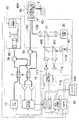
図1は第1の実施形態に係る光立体構造画像化装置の構成を示すブロック図である。図1に示すように、光立体構造画像化装置1は、例えば体腔内の生体組織や細胞等の測定対象の断層画像を例えば波長1.3μmを中心とするSS−OCT計測により取得するものであって、第1波長帯域光源としての(例えば、帯域が700nmから1600nmの光を発する)OCT光源10、第2波長帯域光源としての(例えば、帯域が350nmから1000nmの白色光を発する)可視光光源20、干渉情報検出手段としての干渉情報検出部70を有するOCT干渉計30、プローブ40、受光手段としての可視光情報検出部60及び光構造情報生成手段及び光構造画像生成手段としての3次元CG画像生成部90及びモニタ100を備えて構成される。First embodiment:
FIG. 1 is a block diagram showing the configuration of the optical three-dimensional structure imaging apparatus according to the first embodiment. As shown in FIG. 1, the optical three-dimensional
OCT光源10は周波数を一定の周期で掃引させながら赤外領域である、例えば波長1.3μmを中心とするレーザ光Lを射出する光源であり、可視光光源20は白色光からなる照明光としての可視光Laを射出する光源である。なお、同期手段はOCT光源10により構成され、赤外領域のレーザ光Lの周波数掃引のための掃引トリガ信号Sが同期手段の同期信号となっている。 The OCT
OCT光源10から射出されたレーザ光Lは、OCT干渉計30内の光分波部3により測定光L1と参照光L2とに分波される。光分波部3は、例えば、分岐比99:1の光カプラから構成され、測定光:参照光=99:1の割合で分波する。 The laser light L emitted from the OCT
OCT干渉計30では、光分波部3により分波された参照光L2は、サーキュレータ5aを介して参照光調整手段としての光路長調整部80により光路長が調整されて反射される。 In the
この光路長調整部80は、断層画像の取得を開始する位置を調整するために参照光L2の光路長を変更するものであり、コリメータレンズ81、82および反射ミラー83を有している。そして、サーキュレータ5aからの参照光L2はコリメータレンズ81、82を透過した後に反射ミラー83により反射され、参照光L2の戻り光L2aは再びコリメータレンズ81、82を介してサーキュレータ5aに入射される。 The optical path
ここで、反射ミラー83は可動ステージ84上に配置されており、可動ステージ84はミラー移動部85により矢印A方向に移動可能に設けられている。そして可動ステージ84が矢印A方向に移動することにより、参照光L2の光路長が変更するようになっている。そして、光路長調整部80からの参照光L2の戻り光L2aは、サーキュレータ5aを介して光合分波部4に導光される。 Here, the reflection mirror 83 is disposed on the
一方、光分波部3により分波された測定光L1は、サーキュレータ5bを介してプローブ40内を挿通するファイバFB1に入射される。 On the other hand, the measurement light L1 demultiplexed by the
また、可視光光源20から出射された可視光Laは、コリメータレンズ20a及びハーフミラー21を介して集光レンズ20bにより集光され、プローブ40内を挿通するファイバFB2に入射される。 The visible light La emitted from the visible
ここで、プローブ40を構成するファイバFB1は1.3μm帯シングルモードファイバであり、同じくプローブ40を構成するファイバFB2はマルチモードファイバである。プローブ40の詳細な構成は後述する。 Here, the fiber FB1 constituting the
なお、OCT測定用のファイバFB1は、OCT光源10の波長帯域に対してシングルモードである必要がある。一方、可視光測定用のファイバFB2は、シングルモードでもマルチモードでもどちらでもよいが、反射光強度が弱い場合はより多くの光を集めるためにマルチモードの方が望ましい。 The OCT measurement fiber FB1 needs to be in a single mode with respect to the wavelength band of the OCT
プローブ40の出射端から可視光La及び測定光L1が出射されて測定対象Tに照射され、その戻り光L3が再びプローブ40に入射し、戻り光のうちの可視光成分の光L3はファイバFB2に、戻り光のうちの赤外光成分である測定光L1の反射光(あるいは後方散乱光)L4はファイバFB1に、それぞれ導光される。 The visible light La and the measurement light L1 are emitted from the emission end of the
ファイバFB2に導光された可視光成分の光は、ハーフミラー21を反射して可視光情報検出部60に導光され、可視光情報検出部60では、可視光成分の光は、それぞれ赤、緑、青のフィルタ110r,110g,110bを前面に貼り付けられた3つのSiフォトディテクタ111r,111g,111bに入射され、OCT光源10の掃引トリガ信号Sに同期して可視光検出部112にてその瞬間の赤、緑、青の各光強度が検出される。 The visible light component light guided to the fiber FB2 is reflected by the
一方、ファイバFB2に導光された反射光(あるいは後方散乱光)L4は、OCT干渉計30に導光され、OCT干渉計30にてサーキュレータ5bを介して光合分波部4に導光される。そして、この光合分波部4において測定光L1の反射光(あるいは後方散乱光)L4と参照光L2の戻り光L2aとを合波し干渉情報検出部70側に射出するようになっている。 On the other hand, the reflected light (or backscattered light) L4 guided to the fiber FB2 is guided to the
干渉情報検出部70は、光合分波部4により合波された測定光L1の反射光(あるいは後方散乱光)L4と参照光L2の戻り光L2aとの干渉光L5を、所定のサンプリング周波数で検出するものであり、干渉光L5の光強度を測定するInGaAsフォトディテクタ71aおよび71bと、InGaAsフォトディテクタ71aの検出値とInGaAsフォトディテクタ71bの検出値のバランス検波を行なう干渉光検出部72とを備えている。なお、干渉光L5は、光合分波部4において2分され、InGaAsフォトディテクタ71aおよび71bにおいて検出され、干渉光検出部72に出力される。干渉光検出部72は、OCT光源10の掃引トリガ信号Sに同期して、干渉光L5をフーリエ変換することにより、測定対象Tの各深さ位置における反射光(あるいは後方散乱光)L4の強度を検出する。 The interference
3次元CG画像生成部90は、干渉光検出部72により検出された測定対象Tの各深さ位置における反射光(あるいは後方散乱光)L4の強度を干渉情報として第1メモリ91に格納する。また、3次元CG画像生成部90は、可視光検出部112にて検出された測定対象Tからの可視光成分の光の赤、緑、青の各光強度信号を画像情報として第2メモリ92に格納する。 The three-dimensional CG
3次元CG画像生成部90は、第1の記憶手段としての前記第1メモリ91及び第2の記憶手段としての第2メモリ92のほかに、信号処理部93、制御部94を備えて構成される。 The three-dimensional CG
信号処理部93は、第1メモリ91に格納された干渉情報に基づいて測定対象Tの構造情報からなる光立体構造像を生成すると共に、第2メモリ92に格納された画像情報に基づいて測定対象Tの表面に可視光画像をレンダリングするものである。詳細な構成は後述する。 The
また、制御部94は、信号処理部93を制御すると共に、OCT光源10及び可視光光源20の発光制御を行うと共に、ミラー移動部85を制御するものである。 The
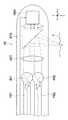
図2は図1のプローブの詳細な構成を示す断面図である。図1の符号40Aの拡大図である図2に示すように、プローブ40では、ファイバFB1、FB2の出射端に光をコリメートするコリメートレンズ451、452が融着されている。 FIG. 2 is a cross-sectional view showing a detailed configuration of the probe of FIG. As shown in FIG. 2, which is an enlarged view of
ファイバFB1から出射される測定光L1は、コリメートレンズ451によりコリメートビームとなる。ファイバFB2から出射される可視光Laも、コリメートレンズ452によりコリメートビームとなる。2本のファイバFB1、FB2の出射端は、それぞれのコリメートビームがほぼ平行となるように配置されている。 The measurement light L1 emitted from the fiber FB1 becomes a collimated beam by the
そして、2本の平行なコリメートビームは、ひとつの集光レンズ460に入射し、次に偏向回転ミラー470で反射され、測定対象Tに照射される。集光レンズ460により2つのビームはほぼ同一の点に集光されて照射される。偏向回転ミラー470は、モータ480により回転し、それにより測定光L1、及び可視光Laの集光点が走査される。 Then, the two parallel collimated beams are incident on one
測定対象Tの深さ方向をZ、プローブの長手軸方向をX、ZX面に直角な方向をYとすると、プローブ40では、偏向回転ミラー470がモータ480により回転し、測定対象T上において円周状に可視光La及び測定光L1が走査され、ZY平面の2次元断層画像が計測可能となっている。なお、モータ480は制御部94の制御に基づき光走査部42により駆動される(図1参照)。 Assuming that the depth direction of the measurement target T is Z, the longitudinal axis direction of the probe is X, and the direction perpendicular to the ZX plane is Y, in the
また、光走査部42(図1参照)内の図示しないモータによりプローブ40の先端が可視光La及び測定光L1の走査円が形成する平面に対して垂直な方向Xに進退走査することにより、XYZの3次元断層画像の計測が可能となっている。 Further, the tip of the
ファイバFB1から出射して測定対象に照射された測定光L1は、測定対象T内で反射、後方散乱され、その一部が集光レンズ460、およびコリメートレンズ451で集められ、ファイバFB1に入射する。 The measurement light L1 emitted from the fiber FB1 and applied to the measurement target is reflected and backscattered in the measurement target T, and a part of the measurement light L1 is collected by the
一方、ファイバFB2から出射して測定対象Tに照射された可視光Laは、測定対象T内で反射、後方散乱され、その一部は、集光レンズ460とコリメートレンズ452で集められ、ファイバFB2に入射する。 On the other hand, the visible light La emitted from the fiber FB2 and applied to the measurement target T is reflected and backscattered in the measurement target T, and a part of the visible light La is collected by the
このように、プローブ40のファイバFB1、FB2は、入射された可視光La及び測定光L1を測定対象Tまで導光し、測定対象Tに照射する。そして、プローブ40のファイバFB1、FB2は、可視光La及び測定光L1が測定対象Tに照射されたときの測定対象Tからのそれぞれの戻り光L4、L3を導光する。 Thus, the fibers FB1 and FB2 of the
勿論、プローブ先端形状や走査方向はこれに限る物ではなく、図18に示すように、例えば、コリメートレンズ451、452を備えたファイバ先端側に集光レンズ460及びガルバノミラー等の高速走査ミラー990を配置した光送受部991を設け、高速走査ミラー990により2次元走査を行ってもよいし、ステージ992によって進退走査するように集光手段及び走査手段を構成してもよい。あるいは、測定対象Tをステージ992によって2次元的に走査してもよい。あるいは、これら光軸走査機構、および測定試料移動機構を組み合わせて構成してもよい。 Of course, the probe tip shape and scanning direction are not limited to this, and as shown in FIG. 18, for example, a high-
図3は図1の信号処理部の構成を示すブロック図である。信号処理部93は、図3に示すように、第1メモリ91に格納された干渉情報に基づいて測定対象Tの構造情報からなる光立体構造像を構築する光構造情報生成手段としての3次元化部120と、3次元化部120により構築された光立体構造像の表面の位置情報である測定対象Tの表面位置を算出する表面位置算出手段としての表面位置算出部121と、第2メモリ92に格納された画像情報に基づいて測定対象Tの可視光画像を生成する画像情報生成手段としての可視光画像生成部122と、3次元化部120からの光立体構造像、表面位置算出部121からの表面の位置情報及び可視光画像生成部122からのカラー画像に基づいて、光立体構造像の表面に可視光画像をレンダリングした光構造画像である3次元CG画像を生成するレンダリング手段としてのレンダリング部123とを備えて構成され、これら各部は制御部94に制御され、レンダリング部123は生成した3次元CG画像をモニタ100に出力するようになっている。 FIG. 3 is a block diagram showing the configuration of the signal processing unit of FIG. As shown in FIG. 3, the
なお、光構造情報は干渉情報に基づいた測定対象Tの深さ方向の構造情報であり、光立体構造像は測定対象Tの光構造情報からなる光立体構造モデルであり、光構造画像は光立体構造像の表面に可視光画像をレンダリングした3次元CG画像である。 The optical structure information is the structure information in the depth direction of the measurement target T based on the interference information, the optical three-dimensional structure image is an optical three-dimensional structure model composed of the optical structure information of the measurement target T, and the optical structure image is a light It is the three-dimensional CG image which rendered the visible light image on the surface of the three-dimensional structure image.
光構造画像生成手段は、表面位置算出手段としての表面位置算出部121と、画像情報生成手段としての可視光画像生成部122と、レンダリング手段としてのレンダリング部123とにより構成される。 The optical structure image generation unit includes a surface
なお、表面位置算出部121は、例えば空間から対象物に移るOCT信号強度の変化から、測定対象Tの表面位置を算出する。 The surface
次に、このように構成された本実施形態の光立体構造画像化装置1の作用を図4のフローチャートを用いて説明する。図4は図1の光立体構造画像化装置の3次元CG画像生成処理の流れを示すフローチャートである。 Next, the operation of the optical three-dimensional
図4に示すように、制御部94は、OCT光源10及び可視光光源20を制御し赤外光及び可視光の発光制御を開始する(ステップS1)。この赤外光の発光制御では、OCT光源10は掃引トリガ信号Sに同期して周波数を一定の周期で掃引させながら赤外領域のレーザ光Lを射出する。 As shown in FIG. 4, the
次に、制御部94は、干渉光検出部72により検出された測定対象Tの各深さ方向Z位置における反射光(あるいは後方散乱光)L4の強度を干渉情報として第1メモリ91に格納すると共に、可視光検出部112にて検出された測定対象Tからの可視光成分の光の赤、緑、青の各光強度信号を画像情報として第2メモリ92に格納する(ステップS2)。 Next, the
続いて、制御部94は、光走査部42を制御して測定対象T上において可視光La及び測定光L1をY方向走査し(ステップS3)、このY方向走査が終了するまでステップS2〜ステップS3の処理を繰り返す(ステップS4)。 Subsequently, the
このY方向走査が終了すると、制御部94は、光走査部42を制御して測定対象T上において可視光La及び測定光L1をX方向走査し(ステップS5)、このX方向走査が終了するまでステップS2〜ステップS5の処理を繰り返す(ステップS6)。 When the Y-direction scanning is completed, the
このX方向走査が終了すると、制御部94は、3次元化部120を制御して第1メモリ91に格納された干渉情報に基づいて測定対象Tの光立体構造像を構築する(ステップS7)。 When this X-direction scanning is completed, the
また、制御部94は、表面位置算出部121を制御して3次元化部120により構築された光立体構造像の表面の位置情報を算出する(ステップS8)。 Further, the
さらに、制御部94は、可視光画像生成部122を制御して第2メモリ92に格納された画像情報に基づいて測定対象Tの可視光画像を生成する(ステップS9)。 Further, the
そして、制御部94は、レンダリング部123を制御して3次元化部120からの3光立体構造像、表面位置算出部121からの表面の位置情報及び可視光画像生成部122からの可視光画像に基づいて、光立体構造像の表面に可視光画像をレンダリングした3次元CG画像を生成し(ステップS10)、モニタ100に3次元CG画像を表示して(ステップS11)、処理を終了する。 Then, the
このように本実施形態では、光立体構造像の表面位置に、OCT光源10の掃引トリガ信号Sに同期した同じタイミングで取得した画像情報である可視光画像情報をレンダリングすることにより、光立体構造像の表面に可視光表面情報を備えることとなり、図5に示すように、上面からは通常の可視光画像200がフルカラーで表示され、その下にOCTで得られた光立体構造像201が表示された光構造画像である3次元CG画像203が完成する。OCT情報を元に表面画像として可視光画像200を貼り付けているため、モニタ100に表示される3次元CG画像203は立体感のある表面画像を有する画像になる。 As described above, in the present embodiment, by rendering visible light image information that is image information acquired at the same timing synchronized with the sweep trigger signal S of the OCT
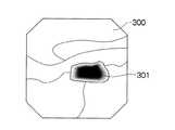
特に、本実施形態の光立体構造画像化装置1を、例えば可視光を照明光とする通常の電子内視鏡装置と共に使用する場合、プローブ40を電子内視鏡の処置具チャンネル等に挿通させることになるが、電子内視鏡が測定対象Tとして体腔内の患部を撮像した場合、図6に示すような内視鏡画像300がモニタ等に表示される。 In particular, when the optical three-dimensional
このとき、例えば内視鏡画像300上から患部領域301が視認できた場合、この患部領域301に対してプローブ40によりOCT測定を行い、患部領域301の光立体構造像を得ることになる。 At this time, for example, when the affected
図5は図4の処理により生成される3次元CG画像を示す図であり、図6は図5の3次元CG画像と対比される内視鏡画像の一例を示す図である。 FIG. 5 is a diagram showing a three-dimensional CG image generated by the processing of FIG. 4, and FIG. 6 is a diagram showing an example of an endoscopic image compared with the three-dimensional CG image of FIG.
内視鏡画像の視野に比べ患部領域301が小さいために、OCT測定を行った領域が患部領域301であるかどうかを光立体構造像から判断することは困難であるが、本実施形態では、3次元CG画像203の表面の可視光画像200上の患部領域301(図5参照)の可視光表面情報(色相、コントラスト、輝度等)と内視鏡画像上での患部領域301(図6参照)の可視光画像情報(色相、コントラスト、輝度等)を対応させて識別することができるので、患部領域301が確実にOCT測定されたかどうかを容易に判断することができる。 Since the affected
従来のOCT画像だけでは、画質が大きく異なるために通常内視鏡の画像との位置あわせが困難だったが、可視光表面情報が光立体構造像に添付されていることで、パターンマッチングで視野の広い内視鏡画像中の位置の特定が容易になる。 Conventional OCT images alone have been difficult to align with normal endoscopic images because the image quality is significantly different. However, the visible light surface information is attached to the optical 3D structure image, so the field of view can be reduced by pattern matching. The position in the wide endoscope image can be easily specified.
さらに、この3次元CG画像では、通常内視鏡画像で視認できる病変の特徴と、光立体構造像の特徴を複合的に利用した病変部の抽出が可能となり、分解能が高く、病変部の境界がより高精度に見極めることができる。 Furthermore, in this three-dimensional CG image, it is possible to extract a lesion part using a feature of a lesion that can be visually recognized in a normal endoscopic image and a feature of an optical three-dimensional structure image, and the resolution is high. Can be determined with higher accuracy.
プローブ40は、コリメートレンズ451、452が融着されたファイバFB1、FB2と、集光レンズ460と、偏向回転ミラー470と、モータ480とにより構成するとしたが、これに限らず、以下の<変形例1>から<変形例5>のように構成してよい。 The
<変形例1>図7は図2のプローブの変形例1の構成を示す図である。 <
図7に示すように、プローブの変形例1では、集光レンズ460を2つの集光レンズ460a、460bとする。この場合、ファイバFB1から出射される測定光L1は、コリメートレンズ451によりコリメートビームとなる。ファイバFB2から出射される可視光Laも、コリメートレンズ452によりコリメートビームとなる。そして、2本の平行なコリメートビームは、2つの集光レンズ460a、460bにそれぞれ入射し、次に偏向回転ミラー470で反射され、測定対象Tに照射される。 As shown in FIG. 7, in the
<変形例2>図8は図2のプローブの変形例2の構成を示す図であり、図9は図8のA−A線断面を示す図であり、図10は図8のプローブに適用される光立体構造画像化装置の構成を示す図である。 <Modification 2> FIG. 8 is a diagram showing a configuration of Modification 2 of the probe of FIG. 2, FIG. 9 is a diagram showing a cross section taken along line AA of FIG. 8, and FIG. 10 is applied to the probe of FIG. It is a figure which shows the structure of the optical three-dimensional structure imaging device.
図8に示すように、プローブの変形例2は、プローブ40に使うファイバを3本にした例である。すなわち、プローブの変形例2では、可視光用のファイバFB2を照明用のファイバFB21と反射光受光用のファイバFB22に分けて構成する。そして、図9に示すように、FB21、22の先端にはコリメートレンズ452a、452bが設けられている。このように可視光のファイバFB2を照明用のファイバFB21と反射光受光用のファイバFB22に分けると、図10に示すように、光立体構造画像化装置1では、ハーフミラー21が不要になるために光利用効率が高くなる。 As shown in FIG. 8, Modification 2 of the probe is an example in which three fibers are used for the
なお、プローブ40に使うファイバは2本に限らず、用途に合わせて何本でも重ねて良い。例えば、図示はしないが、OCT測定光用のファイバFB1に照射用と反射用とで2本のファイバを用いるようにしてもよい。この場合、偏波保存ファイバを2本用いて、互いに垂直な偏光を照射、あるいは受光するようにしてもよい。以下に、変形例2の具体例を実施例1ないし3として説明する。 The number of fibers used for the
実施例1:本実施形態では、可視光画像を得るための照明光として白色光である可視光Laを用いたが、照明光としては白色光に限らない。例えば、青色レーザを照射して細胞の自家蛍光を受光することで病変部を視認しやすくする蛍光内視鏡がある。この蛍光内視鏡で用いられる青色励起光を照明光として用い、この青色励起光をファイバFB21により導波し、細胞の自家蛍光をファイバFB22により導波する。細胞の自家蛍光を受光するディテクタに緑色の蛍光を透過するフィルタを用いることで、蛍光内視鏡と同様な画像とOCTを組み合わせた表示ができ、よりがんの領域の視認性を上げることができる。あるいは、がんに選択的に集積し、特定の蛍光を発する薬剤を注入し、その励起光を照明光として使い、その励起光に合わせたファイバをファイバFB21として用い、その蛍光波長を選択的に受光するディテクタとその波長に合わせたファイバFB22を組み合わせることでも、よりがんの領域の視認性を上げることができる。 Example 1: In this embodiment, visible light La that is white light is used as illumination light for obtaining a visible light image, but the illumination light is not limited to white light. For example, there is a fluorescence endoscope that makes it easy to visually recognize a lesion by irradiating a blue laser to receive autofluorescence of cells. The blue excitation light used in the fluorescence endoscope is used as illumination light, the blue excitation light is guided by the fiber FB21, and the autofluorescence of the cell is guided by the fiber FB22. By using a filter that transmits green fluorescence to the detector that receives the autofluorescence of the cells, it is possible to display a combination of the same image and OCT as a fluorescence endoscope, and to improve the visibility of the cancer area. it can. Alternatively, an agent that selectively accumulates in cancer and injects specific fluorescence is injected, the excitation light is used as illumination light, a fiber matched to the excitation light is used as fiber FB21, and the fluorescence wavelength is selectively selected. The visibility of the cancer area can be further improved by combining the detector for receiving light and the fiber FB22 matched to the wavelength.
また、励起光、および蛍光は、可視域とは限らない。例えば、インドシアニングリーンという公知の蛍光材料は、不可視領域である800nm〜810nmの領域に吸収波長があり、806nmのレーザ光で励起されると不可視領域である波長830nmの蛍光を発色する。従って、照明光には806nmレーザ、ディテクタには806nm近傍の光を除去し830nm近傍の光を抽出するフィルタを用いることで、インドシアニングリーンが集積しているXY平面上の領域を光立体構造像に明示することができる。また、インドシアニングリーンを静脈注射し、粘膜深部の血管を強調表示する公知の技術がある。OCT断層像だけでは血管と他の腺管との区別が難しいが、XY平面上での血管位置が明瞭となることで、3次元的な血管網を描画することができる。 Moreover, excitation light and fluorescence are not necessarily in the visible range. For example, a known fluorescent material called indocyanine green has an absorption wavelength in the invisible region of 800 nm to 810 nm, and emits fluorescence with a wavelength of 830 nm in the invisible region when excited with a laser beam of 806 nm. Therefore, by using a filter that removes the light near 806 nm and extracts the light near 830 nm as the illumination light for the 806 nm laser and the detector, the region on the XY plane where the indocyanine green is accumulated is shown as an optical three-dimensional structure image. Can be specified. There is also a known technique in which indocyanine green is injected intravenously and blood vessels in the deep mucosa are highlighted. Although it is difficult to distinguish between a blood vessel and other gland ducts using only an OCT tomogram, a three-dimensional blood vessel network can be drawn by clarifying the blood vessel position on the XY plane.
実施例2:ファイバFB21として分散シフトファイバを用いて超短パルスレーザを導波し、超短パルスレーザを測定対象に照射した際に発生する2光子励起蛍光や第二次高調波を導波するマルチモードファイバをファイバFB22として組み合わせる構成としてもよい。あるいは、中空ファイバを用いて紫外光を測定対象に照射させ、蛍光を受光するように構成してもよい。 Example 2: An ultrashort pulse laser is guided using a dispersion shifted fiber as the fiber FB21, and two-photon excitation fluorescence and second harmonics generated when the measurement object is irradiated with the ultrashort pulse laser are guided. It is good also as a structure which combines a multimode fiber as fiber FB22. Alternatively, the measurement object may be irradiated with ultraviolet light using a hollow fiber to receive fluorescence.
実施例3:ラマン分光法やコヒーレントアンチストークスラマン分光法(CARS)と組み合わせて構成してもよい。CARSと組み合わせる場合、波長568nmと600nmの励起光を用い、照射用ファイバにはそれぞれの別々のシングルモードファイバからなる2本のファイバFB21を用い、さらに受光用のマルチモードファイバをファイバFB22として束ねる。この実施例3においては、プローブ40の先端では、CARS測定に適した角度でビームが照射、集光されるように各ファイバ先端の位置と光学系が調整されて設けられている。また、受光用のマルチモードファイバであるファイバFB22の受光端には分光素子、及び1次元フォトディテクタからなる分光器が備え付けられ、分光情報が取得されるようになっている。このようなCARS信号、あるいはラマン分光情報と組み合わせることで、測定対象の組成の違いやミトコンドリアの代謝活性情報と光構造画像が一体化された映像が得られる。 Example 3: A configuration may be combined with Raman spectroscopy or coherent anti-Stokes Raman spectroscopy (CARS). When combined with CARS, excitation light having a wavelength of 568 nm and 600 nm is used, two fibers FB21 made of separate single mode fibers are used as irradiation fibers, and a multimode fiber for light reception is bundled as a fiber FB22. In the third embodiment, the position of the tip of each fiber and the optical system are adjusted so that the beam is irradiated and condensed at an angle suitable for CARS measurement at the tip of the
<変形例3>図11は図2のプローブの変形例3の構成を示す図である。 <
図11に示すように、プローブの変形例3は、上記変形例2とほとんど同じであって、紫外レーザ光を発する紫外レーザ光源(不図示)と、ファイバFB21の先端に塗られた蛍光塗料455とから可視光光源20を構成した例である。ファイバFB21は紫外レーザ光を導波し、紫外レーザ光がファイバFB2の先端の蛍光塗料で吸収される。蛍光塗料は白色の蛍光を発し、照明光となる。これを集光して照射し、その反射光を受光用マルチモードファイバからなる射光受光用のファイバFB22で導波し、光立体構造画像化装置1に備え付けられた可視光情報検出部60で受光する。 As shown in FIG. 11,
<変形例4>図12は図2のプローブの変形例4の構成を示す図である。 <Modification 4> FIG. 12 shows the structure of Modification 4 of the probe shown in FIG.
図12に示すように、プローブの変形例4は、ファイバFB1、FB2の代わりに、ファイバとしてシングルモードダブルクラッドファイバ490を用い、コリメートレンズ491を別体に設け、偏向回転ミラー470の代わりにガルバノミラー492を設けた構成例である。シングルモードダブルクラッドファイバ490のコア490aはファイバFB1に代わるシングルモード導波路になっており、シングルモードダブルクラッドファイバ490のクラッド490bはファイバFB2に代わる可視光が伝搬するマルチモード導波路となっている。このシングルモードダブルクラッドファイバ490を用いれば、複数本のファイバをバンドル化する必要がなく、プローブがより細径化できる。 As shown in FIG. 12, the probe modification 4 uses a single mode double clad
<変形例5>図13は図2のプローブの変形例5の構成を示す図である。 <
図13に示すプローブの変形例5のように、各ファイバFB1、FB2の先端に設けられるコリメートレンズと集光レンズは、それぞれひとつの光学レンズ495a、495bにまとめてもよい。 As in
このように構成することで、プローブ40がよりコンパクトになる。逆に、図示はしないが、複数のレンズを組み合わせて、より高解像度化してもよい。組合せレンズを用いて色収差をなくすことがより望ましい。 With this configuration, the
なお、可視光情報検出部60は、それぞれ赤、緑、青のフィルタ110r,110g,110bを前面に貼り付けられた3つのSiフォトディテクタ111r,111g,111bにより、OCT光源10の掃引トリガ信号Sに同期して可視光成分の光に対して可視光検出部112にてその瞬間の赤、緑、青の各光強度を画像情報として検出するとしたがこれに限らず、可視光情報検出部60を以下の(1)から(4)のように構成してよい。 Note that the visible light
(1)図14は図1の可視光情報検出部の第1の変形例を示す図である。図14に示すように、2つのダイクロイックミラー400,401により可視光成分の光を赤、緑、青を分け、フィルタのない3つのSiフォトディテクタ111r,111g,111bにて、OCT光源10の掃引トリガ信号Sに同期して可視光成分の光に対して可視光検出部112にてその瞬間の赤、緑、青の各光強度を画像情報として検出するように可視光情報検出部60を構成してもよい。 (1) FIG. 14 is a diagram showing a first modification of the visible light information detection unit of FIG. As shown in FIG. 14, red, green, and blue light components are divided into red, green, and blue by two
(2)図15は図1の可視光情報検出部の第2の変形例を示す図である。図15に示すように、回折格子410にて可視光成分の光を赤、緑、青を分け、フィルタのない3つのSiフォトディテクタ111r,111g,111bにて、OCT光源10の掃引トリガ信号Sに同期して可視光成分の光に対して可視光検出部112にてその瞬間の赤、緑、青の各光強度を画像情報として検出するように可視光情報検出部60を構成してもよい。 (2) FIG. 15 is a diagram showing a second modification of the visible light information detection unit of FIG. As shown in FIG. 15, red, green, and blue are divided into visible light components by the
(3)図16は図1の可視光情報検出部の第3の変形例を示す図である。図16に示すように、WDM(Wavelength Division Multiplexing)カップラやAWG(Arrayed Waveguide Grating)のような全ファイバ光学系420を用いて可視光成分の光を赤、緑、青を分け、フィルタのない3つのSiフォトディテクタ111r,111g,111bにて、OCT光源10の掃引トリガ信号Sに同期して可視光成分の光に対して可視光検出部112にてその瞬間の赤、緑、青の各光強度を画像情報として検出するように可視光情報検出部60を構成してもよい。 (3) FIG. 16 is a diagram showing a third modification of the visible light information detection unit of FIG. As shown in FIG. 16, the visible light component light is divided into red, green, and blue using an all-fiber
(4)図17は図1の可視光情報検出部の第4の変形例を示す図である。図17に示すように、可視光情報検出部60のディテクタで色を分けるかわりに、可視光光源20からの照明光の色を時間分割照射してもよい。すなわち、照明光に赤、緑、青のレーザを用いて可視光光源20を構成することで、それぞれ赤、緑、青のレーザの発光時間帯が重ならないようにパルス的に照射し、可視光情報検出部60においてひとつのSiフォトディテクタ111で受光する。可視光光源20のレーザの発光タイミングと可視光情報検出部60の検出タイミングは掃引トリガ信号Sで同期させ、時間帯に応じて発光している色の情報としてコンピュータに入力し、フルカラー画像を生成する。なお、レーザの代わりに、色フィルタを通した白色光源を用い、色フィルタを時間的に切り替えてもよい。 (4) FIG. 17 is a diagram showing a fourth modification of the visible light information detection unit in FIG. As shown in FIG. 17, the color of the illumination light from the visible
なお、本実施形態ではSS−OCT計測を例に説明したがこれに限らず、TD−OCT計測、SD−OCT計測に対しても適用できる。掃引トリガ信号Sに対応するトリガ信号としては、TD−OCT計測の場合は光路長遅延回路の周期となり、SD−OCT計測の場合はOCT用ディテクタアレイの信号取得周期となる。 In addition, although this embodiment demonstrated SS-OCT measurement to the example, it is not restricted to this, It can apply also to TD-OCT measurement and SD-OCT measurement. The trigger signal corresponding to the sweep trigger signal S is the period of the optical path length delay circuit in the case of TD-OCT measurement, and the signal acquisition period of the OCT detector array in the case of SD-OCT measurement.
また、複数の色情報を取得するには、赤、緑、青に限らず、どの波長域でもよい。例えば、癌のスクリーニングに公知のNBI(Narrow Band Imaging)と呼ばれる手法や公知のFICE(Flexible spectral Imaging Color Enhancement)と呼ばれる手法がある。これらは、青、緑の波長域を画像化することで、病変部の特徴を視認しやすくする手法である。このNBI/FICE画像と重ねるには、NBI/FICEで用いる緑、青のフィルタと同じ波長域の物を用いることが望ましい。これにより、光立体構造像上でもより病変部の抽出がしやすくなる。ディテクタの数は3つに限らず、通常内視鏡と同じ赤緑青の他に、NBIや蛍光内視鏡などの特殊光観察に対応したディテクタを配置してもよい。 In addition, in order to acquire a plurality of pieces of color information, not only red, green, and blue, but any wavelength range may be used. For example, there is a known technique called NBI (Narrow Band Imaging) or a known technique called FICE (Flexible Spectral Imaging Color Enhancement) for cancer screening. These are techniques that make it easy to visually recognize the characteristics of a lesion by imaging the blue and green wavelength regions. In order to overlap the NBI / FICE image, it is desirable to use an object having the same wavelength range as the green and blue filters used in the NBI / FICE. This makes it easier to extract a lesion even on an optical three-dimensional structure image. The number of detectors is not limited to three, and a detector corresponding to special light observation such as NBI or fluorescent endoscope may be arranged in addition to the same red, green, and blue as the normal endoscope.
OCT装置の光軸走査は、プローブを用いたものでも、ガルバノミラーを用いたものでも、ステージによって走査するタイプでも、どれでもよい。プローブの場合、偏向ミラーのみモータで回転させても、ファイバに固定して、ファイバ毎回転させてもよい。回転に限らず、MEMS(Micro Electro Mechanical Systems)ミラーを用いて線形走査させてもよい。 The optical axis scanning of the OCT apparatus may be performed using a probe, a galvanometer mirror, or a type that scans using a stage. In the case of a probe, only the deflecting mirror may be rotated by a motor, or it may be fixed to a fiber and rotated for each fiber. In addition to rotation, linear scanning may be performed using a MEMS (Micro Electro Mechanical Systems) mirror.
なお、照明光としての可視光Laは、エイミング光(測定位置を明示する目印光)としての効果もある。また、内視鏡の照明光など、周囲の照明光だけで充分な照度が得られる場合は、照明光はなくてもよい。 The visible light La as illumination light also has an effect as aiming light (marking light that clearly indicates the measurement position). In addition, when sufficient illuminance can be obtained with only ambient illumination light such as illumination light of an endoscope, there is no need for illumination light.
以上、本発明の光立体構造像装置としての光立体構造画像化装置について詳細に説明したが、本発明は、以上の例には限定されず、本発明の要旨を逸脱しない範囲において、各種の改良や変形を行ってもよいのはもちろんである。 As mentioned above, although the optical three-dimensional structure imaging device as the optical three-dimensional structure image device of the present invention has been described in detail, the present invention is not limited to the above examples, and various types can be made without departing from the gist of the present invention. Of course, improvements and modifications may be made.
10…OCT光源、20…可視光光源、30…OCT干渉計、40…プローブ、60…可視光情報検出部、70…干渉情報検出部、90…断層画像生成部、91…第1メモリ、92…第2メモリ、93…信号処理部、94…制御部、100…モニタ、120…3次元化部、121…表面位置算出部、122…可視光画像生成部、123…レンダリング部、451、452…コリメートレンズ、460…集光レンズ、470…偏向回転ミラー、480…モータ、FB1、FB2…ファイバDESCRIPTION OF
Claims (18)
Translated fromJapanese前記第1の波長帯域の光を測定光と参照光に分離する光分離手段と、
前記測定光を導波する第1の導波手段と、
前記第1の導波手段を導波した前記測定光を測定対象に照射する照射手段と、
前記測定対象上の点からの前記測定光に基づく光を前記第1の導波手段に集光する第1の集光手段と、
前記第1の導波手段を導波した前記測定対象上の前記点からの前記測定光に基づく光と、
前記参照光との干渉情報を検出する干渉情報検出手段と、
前記測定対象上の前記点からの前記第1の波長帯域とは異なる第2の波長帯域の光を集光する第2の集光手段と、
前記第2の集光手段が集光した前記第2の波長帯域の光を導波する第2の導波手段と、
前記第2の導波手段を導波した前記第2の波長帯域の光を受光し受光信号を取得する受光手段と、
前記第1の集光手段及び前記第2の集光手段により集光する前記測定対象上の前記点を走査する走査手段と、を備え、
前記第2の波長帯域の光を発する第2波長域光源をさらに備え、前記走査手段は、前記測定光及び前記第2波長域光源からの前記第2の波長帯域の光を合波し、この合波された前記測定光及び前記第2の波長帯域の光を走査し、
前記第2の導波手段は、第2波長域光源が発した前記第2の波長帯域の光を前記第2の集光手段に導波する光源用導波路と、第2の集光手段が集光した前記測定対象上の前記点からの前記第2の波長帯域の光を前記受光手段に導波する受光用導波路とからなり、
前記第2波長域光源は、紫外線を発する紫外線光源部と、前記光源用導波路の先端に設けられ前記紫外線により白色蛍光を発する白色蛍光部と、を有することを特徴とする光立体構造像装置。A first wavelength band light source that emits light in a first wavelength band;
A light separating means for separating the light in the first wavelength band into measurement light and reference light;
First waveguide means for guiding the measurement light;
Irradiating means for irradiating the measuring object with the measurement light guided through the first waveguide means;
First condensing means for condensing light based on the measurement light from a point on the measurement object on the first waveguide means;
Light based on the measurement light from the point on the measurement object guided by the first waveguide means;
Interference information detecting means for detecting interference information with the reference light;
Second condensing means for condensing light in a second wavelength band different from the first wavelength band from the point on the measurement object;
Second waveguide means for guiding the light in the second wavelength band condensed by the second light collection means;
A light receiving means for receiving the light of the second wavelength band guided through the second waveguide means and obtaining a light reception signal;
Scanning means for scanning the point on the measurement object condensed by the first light collecting means and the second light collecting means,
A second wavelength band light source that emits light of the second wavelength band; and the scanning unit combines the measurement light and the light of the second wavelength band from the second wavelength band light source, Scanning the combined measurement light and the second wavelength band light;
The second waveguide means includes a light source waveguide for guiding the light in the second wavelength band emitted from the second wavelength band light source to the second light collecting means, and a second light collecting means. A light receiving waveguide for guiding the light of the second wavelength band from the point on the measurement target to the light receiving means;
The second wavelength range light source includes an ultraviolet light source part that emits ultraviolet light, and a white fluorescent part that is provided at a tip of the light source waveguide and emits white fluorescence by the ultraviolet light. .
前記第1波長域光源は広帯域の低コヒーレント光を前記第1の波長帯域の光とする光源であり、前記干渉情報検出手段は前記測定光の前記測定対象からの反射光と前記参照光の前記反射ミラーからの反射光との干渉光の周波数成分毎の強度を検出するディテクタアレイを備え所定のトリガ信号に基づいて前記ディテクタアレイより前記干渉情報を検出し、前記同期手段は前記トリガ信号に基づいて前記干渉情報検出手段での前記干渉情報の検出タイミングと前記受光手段での前記受光信号の取得タイミングとを同期させることを特徴とする請求項11に記載の光立体構造像装置。The optical path length varying means includes a reflection mirror that reflects the reference light,
The first wavelength range light source is a light source that uses broadband low-coherent light as light in the first wavelength band, and the interference information detection means is configured to reflect the measurement light reflected from the measurement object and the reference light. A detector array for detecting the intensity of each frequency component of the interference light with the reflected light from thereflection mirror is provided to detect the interference information from the detector array based on a predetermined trigger signal, and the synchronization means is based on the trigger signal The optical three-dimensional structure image apparatus according toclaim 11 , wherein the interference information detection means in the interference information detection means synchronizes with the light receptionsignal acquisition timing in the light receiving means.
前記受光手段が取得した前記受光信号を記憶する第2の記憶手段と、
前記第1の記憶手段に記憶されている前記干渉情報に基づき、前記測定対象上の任意の点における前記測定光の光路長に依存した光構造情報を生成する光構造情報生成手段と、
前記走査手段の走査情報と前記光構造情報と前記第2の記憶手段に記憶されている前記受光信号に基づき、光構造画像を生成する光構造画像生成手段と、
をさらに備えたことを特徴とする請求項1ないし13のいずれか1つに記載の光立体構造像装置。First storage means for storing the interference information detected by the interference information detection means;
Second storage means for storing thereceived light signal acquired by thelight receiving means;
Based on the interference information stored in the first storage means, optical structure information generation means for generating optical structure information depending on the optical path length of the measurement light at an arbitrary point on the measurement target;
An optical structure image generating unit configured to generate an optical structure image based on the scanning information of the scanning unit, the optical structure information, and the received lightsignal stored in the second storage unit;
It claims 1 to, further comprising a to optical stereoscopic structure image apparatus according to any one of13.
前記光構造画像生成手段は、
前記測定対象の表面位置を算出する表面位置算出手段と、
前記第2の記憶手段に記憶されている前記受光信号に基づき、前記測定対象の画像情報を生成する画像情報生成手段と、
前記画像情報を前記表面位置に対応する前記3次元構造情報の位置にレンダリングするレンダリング手段と、
からなることを特徴とする請求項14に記載の光立体構造像装置。Theoptical structure information is three-dimensional structure information,
The optical structure image generation means includes
Surface position calculating means for calculating the surface position of the measurement object;
Image information generating means for generating image information of the measurement object based on the received lightsignal stored in the second storage means;
Rendering means for rendering the image information at a position of the three-dimensional structure information corresponding to the surface position;
The optical three-dimensional structure image device according toclaim 14 , comprising:
Priority Applications (2)
| Application Number | Priority Date | Filing Date | Title |
|---|---|---|---|
| JP2008314837AJP5162431B2 (en) | 2008-12-10 | 2008-12-10 | Optical three-dimensional structure image device |
| PCT/JP2009/070583WO2010067813A1 (en) | 2008-12-10 | 2009-12-09 | Optical stereographic structure image apparatus and optical signal processing method therefor |
Applications Claiming Priority (1)
| Application Number | Priority Date | Filing Date | Title |
|---|---|---|---|
| JP2008314837AJP5162431B2 (en) | 2008-12-10 | 2008-12-10 | Optical three-dimensional structure image device |
Publications (2)
| Publication Number | Publication Date |
|---|---|
| JP2010139327A JP2010139327A (en) | 2010-06-24 |
| JP5162431B2true JP5162431B2 (en) | 2013-03-13 |
Family
ID=42242801
Family Applications (1)
| Application Number | Title | Priority Date | Filing Date |
|---|---|---|---|
| JP2008314837AExpired - Fee RelatedJP5162431B2 (en) | 2008-12-10 | 2008-12-10 | Optical three-dimensional structure image device |
Country Status (2)
| Country | Link |
|---|---|
| JP (1) | JP5162431B2 (en) |
| WO (1) | WO2010067813A1 (en) |
Families Citing this family (13)
| Publication number | Priority date | Publication date | Assignee | Title |
|---|---|---|---|---|
| JP5657941B2 (en) | 2010-07-30 | 2015-01-21 | 株式会社トプコン | Optical tomographic imaging apparatus and operating method thereof |
| JP5663241B2 (en)* | 2010-08-31 | 2015-02-04 | 株式会社トプコン | Optical tomographic imaging apparatus and operating method thereof |
| JP5663240B2 (en)* | 2010-08-31 | 2015-02-04 | 株式会社トプコン | Optical tomographic imaging apparatus and operating method thereof |
| US9046337B2 (en)* | 2010-12-30 | 2015-06-02 | Volcano Corporation | Integrated OCT detector system with transimpedance amplifier |
| US8437007B2 (en) | 2010-12-30 | 2013-05-07 | Axsun Technologies, Inc. | Integrated optical coherence tomography system |
| JP5796738B2 (en)* | 2011-09-22 | 2015-10-21 | アイシン精機株式会社 | Terahertz wave generation detection device and terahertz wave propagation device |
| US8982338B2 (en)* | 2012-05-31 | 2015-03-17 | Thermo Scientific Portable Analytical Instruments Inc. | Sample analysis |
| CN104704349B (en)* | 2012-10-19 | 2018-01-02 | 株式会社日立制作所 | CARS microscopes |
| JP6082273B2 (en)* | 2013-02-25 | 2017-02-15 | 日本板硝子株式会社 | Fluorescence detection device |
| EP2983579B1 (en)* | 2013-04-12 | 2025-07-09 | NinePoint Medical, Inc. | Multiple aperture, multiple modal optical systems and methods |
| JP6364305B2 (en)* | 2014-10-09 | 2018-07-25 | 株式会社四国総合研究所 | Hydrogen gas concentration measuring apparatus and method |
| WO2017186529A1 (en)* | 2016-04-27 | 2017-11-02 | Lumileds Holding B.V. | Laser-based light source |
| WO2019142896A1 (en)* | 2018-01-18 | 2019-07-25 | 株式会社アサヒビジョン | Living-body tissue analysis device and living-body tissue analysis method |
Family Cites Families (7)
| Publication number | Priority date | Publication date | Assignee | Title |
|---|---|---|---|---|
| US6975898B2 (en)* | 2000-06-19 | 2005-12-13 | University Of Washington | Medical imaging, diagnosis, and therapy using a scanning single optical fiber system |
| JP4624605B2 (en)* | 2001-08-03 | 2011-02-02 | オリンパス株式会社 | Optical imaging device |
| AU2005270037B2 (en)* | 2004-07-02 | 2012-02-09 | The General Hospital Corporation | Endoscopic imaging probe comprising dual clad fibre |
| JP4838032B2 (en)* | 2006-03-31 | 2011-12-14 | テルモ株式会社 | Diagnostic imaging apparatus and processing method thereof |
| JP4855150B2 (en)* | 2006-06-09 | 2012-01-18 | 株式会社トプコン | Fundus observation apparatus, ophthalmic image processing apparatus, and ophthalmic image processing program |
| JP4869896B2 (en)* | 2006-12-07 | 2012-02-08 | 富士フイルム株式会社 | Optical tomographic imaging system |
| JP4971872B2 (en)* | 2007-05-23 | 2012-07-11 | 株式会社トプコン | Fundus observation apparatus and program for controlling the same |
- 2008
- 2008-12-10JPJP2008314837Apatent/JP5162431B2/ennot_activeExpired - Fee Related
- 2009
- 2009-12-09WOPCT/JP2009/070583patent/WO2010067813A1/enactiveApplication Filing
Also Published As
| Publication number | Publication date |
|---|---|
| JP2010139327A (en) | 2010-06-24 |
| WO2010067813A1 (en) | 2010-06-17 |
Similar Documents
| Publication | Publication Date | Title |
|---|---|---|
| JP5162431B2 (en) | Optical three-dimensional structure image device | |
| JP4869877B2 (en) | Optical tomographic imaging system | |
| US10800831B2 (en) | Systems and methods for obtaining information associated with an anatomical sample using optical microscopy | |
| JP4869896B2 (en) | Optical tomographic imaging system | |
| JP4869895B2 (en) | Optical tomographic imaging system | |
| JP2010200820A (en) | Optical three-dimensional structure imaging apparatus and optical signal processing method for the same | |
| JP4642681B2 (en) | Optical tomographic imaging system | |
| US9435956B1 (en) | Spectroscopic imaging probes, devices, and methods | |
| EP1945094B1 (en) | Spectral- and frequency- encoded fluorescence imaging | |
| JP4895277B2 (en) | Optical tomographic imaging system | |
| JP5541831B2 (en) | Optical tomographic imaging apparatus and operating method thereof | |
| JP2008128709A (en) | Optical tomographic imaging system | |
| JP2007101250A (en) | Optical tomographic imaging method | |
| JP2009041946A (en) | Optical image measuring device | |
| US8564787B2 (en) | OCT apparatus and interference signal level control method for the same | |
| JP2006026015A (en) | Optical tomographic image acquisition system | |
| JP2008089349A (en) | Optical tomographic imaging system | |
| JP2007212376A (en) | Optical tomographic imaging system | |
| WO2010064516A1 (en) | Optical three-dimensional structure image device and optical signal processing method therefor | |
| JP2010210501A (en) | Optical three-dimensional structure image device | |
| JP2008128707A (en) | Tomographic image processing method, apparatus and program, and optical tomographic imaging system using the same | |
| JP2009300097A (en) | Optical tomographic imaging apparatus | |
| JP5405839B2 (en) | Optical stereoscopic structure observation device, operating method thereof, and endoscope system provided with optical stereoscopic image observation device | |
| WO2016081731A1 (en) | Systems and methods for obtaining information associated with an anatomical sample using optical microscopy | |
| JP2007101264A (en) | Optical tomographic imaging system |
Legal Events
| Date | Code | Title | Description |
|---|---|---|---|
| A621 | Written request for application examination | Free format text:JAPANESE INTERMEDIATE CODE: A621 Effective date:20110809 | |
| A131 | Notification of reasons for refusal | Free format text:JAPANESE INTERMEDIATE CODE: A131 Effective date:20120904 | |
| A521 | Written amendment | Free format text:JAPANESE INTERMEDIATE CODE: A523 Effective date:20121101 | |
| TRDD | Decision of grant or rejection written | ||
| A01 | Written decision to grant a patent or to grant a registration (utility model) | Free format text:JAPANESE INTERMEDIATE CODE: A01 Effective date:20121122 | |
| A61 | First payment of annual fees (during grant procedure) | Free format text:JAPANESE INTERMEDIATE CODE: A61 Effective date:20121217 | |
| R150 | Certificate of patent or registration of utility model | Free format text:JAPANESE INTERMEDIATE CODE: R150 | |
| FPAY | Renewal fee payment (event date is renewal date of database) | Free format text:PAYMENT UNTIL: 20151221 Year of fee payment:3 | |
| LAPS | Cancellation because of no payment of annual fees |