JP5159918B2 - Medical implantable staples - Google Patents
Medical implantable staplesDownload PDFInfo
- Publication number
- JP5159918B2 JP5159918B2JP2011113632AJP2011113632AJP5159918B2JP 5159918 B2JP5159918 B2JP 5159918B2JP 2011113632 AJP2011113632 AJP 2011113632AJP 2011113632 AJP2011113632 AJP 2011113632AJP 5159918 B2JP5159918 B2JP 5159918B2
- Authority
- JP
- Japan
- Prior art keywords
- legs
- staple
- leg
- pair
- same
- Prior art date
- Legal status (The legal status is an assumption and is not a legal conclusion. Google has not performed a legal analysis and makes no representation as to the accuracy of the status listed.)
- Active
Links
Images


Landscapes
- Surgical Instruments (AREA)
Description
Translated fromJapanese本発明は、整形外科領域の手術において用いる医療用打ち込み式ステープルに関する。 The present invention relates to a medical drive-in staple used in an orthopedic surgery.
整形外科領域の手術において医療用の打ち込み式ステープルは、腱・靱帯損傷等の際に、損傷を受け又は再建した腱や靱帯を骨に固定する際に使用されている。また、骨折や骨切りの手術時には骨片間の固定を行う際にも用いられておりその用途は広い。このステープルは通常、専用の挿入抜去器を用いて骨内に挿入され、状況により骨内からステープルが抜去される。
固定力を高めるため脚部に溝やギザギザをつけたステープルは、特許文献2に開示されている。In the surgery in the orthopedic field, medical implantable staples are used to fix a damaged or reconstructed tendon or ligament to a bone in the case of tendon / ligament damage or the like. It is also used for fixing bone fragments during fractures and osteotomy, and has a wide range of uses. The staple is usually inserted into the bone using a dedicated insertion / extraction device, and the staple is extracted from the bone depending on the situation.
Patent Document 2 discloses a staple in which a groove or a knurled leg is provided to increase the fixing force.
整形外科領域においても近年、新しい手術方法や手術器具の開発が著しい。医療用の打ち込み式ステープルも改良が重ねられ、骨内に埋入する脚部分を増やし、あるいは脚部に溝やギザギザをつけて固定力を高め、固定力の増強をはかろうとする試みがなされている。しかし、現時点で小侵襲で固定力の増強が期待できる打ち込み式のステープルは、見あたらない。
現在使用されている、医療用打ち込み式ステープルの問題点として固定力の不足が指摘されており、手術後にステープルが転位やゆるみを生じ、固定していた腱や靱帯、骨などに「ずれ」をきたす場合がある。In recent years, the development of new surgical methods and surgical instruments has also been remarkable in the orthopedic field. Improvements have also been made to medical implantable staples, and attempts have been made to increase the fixing force by increasing the number of legs embedded in the bone, or by attaching grooves or jagged edges to the legs to increase the fixing force. ing. However, at the present time, there are no drive-in staples that can be expected to increase fixation force with minimal invasiveness.
Insufficient fixation force has been pointed out as a problem with medical implantable staples currently in use. After surgery, the staples are displaced or loosened, causing "displacement" to the fixed tendons, ligaments, bones, etc. May come.
また別の問題点として、固定力不足のために早期にリハビリ訓練が行えず、手術後に手術部位の安静を保つためにギプス等で患部の安静を計るための外固定期間が長くなり、関節拘縮や筋力低下などの、いわゆる廃用症候群を招来するケースも少なくない。
上記の問題点を解決するため、固定力の増強が期待でき、手術手技、固定手技が容易で、手術において固定方法の選択肢を広げることができ、プレートやスクリュー固定の代用ともなりうる、医療用打ち込み式ステープルが求められている。Another problem is that early rehabilitation training cannot be performed due to lack of fixation force, and the external fixation period for measuring the rest of the affected area with a cast or the like becomes longer after surgery to maintain the rest of the surgical site. There are many cases of so-called disuse syndromes such as contraction and muscle weakness.
In order to solve the above problems, it is expected that the fixing force can be increased, the surgical technique and the fixing technique are easy, the choice of the fixing method in the operation can be expanded, and it can be used as a substitute for fixing the plate and screw. There is a need for driven staples.
また、手術において骨や靱帯、腱等を固定するに際しては、現在は複数本のステープルを用いる場合も多い。このようなケースに対しては、ステープル本体部の形状を、例えば、コの字状や4角形状にすることによって、1本のステープルでも対処可能にしているが、このような場合でも固定力をより強固にすることが求められている。 In addition, when fixing bones, ligaments, tendons and the like in surgery, a plurality of staples are currently often used. For such cases, the staple body can be dealt with even with a single staple by, for example, a U-shape or a square shape. Is required to be stronger.
本発明による医療用打ち込み式ステープルは、直線状の体部と、該体部において所定の間隔を有した一対の結合部から相互に間隔を同じに保ったまま該直線状の体部に対して垂直に同一方向に延びている一対の脚部を備え、該一対の脚部は該脚部の延長方向及び前記直線状の体部に対して垂直かつ同一方向に湾曲している。
前記脚部のうち前記結合部側の一部を湾曲させずに直線状としてもよい。また、前記一対の脚部の長さを異ならせてもよい。
The medical drive-type staple according to the present invention has a linear body part and a pair of connecting parts having a predetermined interval in the body part, while maintaining the same distance from each other with respect to the linear body part. A pair of leg portions extending vertically in the same direction are provided, and the pair of leg portions are curved in the same direction perpendicular to the extending direction of the leg portionsand the linear body portion .
It is good also as a linear form, without curving a part by the side of the said joint part among the said leg parts. Moreover, you may vary the length of a pair of said leg part.
前記一対の脚部間にさらに1又は複数の相互に間隔を同じに保ったまま該一対の脚部と同一方向に延びかつ同一方向に湾曲している脚部を設けてもよい。
また、前記一対の脚部間にさらに1または複数の相互に間隔を同じに保ったまま該一対の脚部と同一方向に延びている前記一対の脚部より短い直線状の脚部を設けてもよい。また、前記一対の脚部の先端側に該脚部から枝状に延びる枝部を設けてもよい。One or a plurality of legs that extend in the same direction as the pair of legs and are curved in the same direction may be provided between the pair of legs.
Further, one or a plurality of straight legs that are shorter than the pair of legs that extend in the same direction as the pair of legs are provided between the pair of legs while maintaining the same distance from each other. Also good. Moreover, you may provide the branch part extended in a branch shape from this leg part at the front end side of a pair of said leg part.
本発明による医療用打ち込み式ステープルは、3本又は4本の直線状の部材により構成された三角形又は四角形の体部の各角部から、該三角形又は四角形の体部が形成する平面に対して相互に間隔を同じに保ったまま同一方向に垂直に延びている複数の脚部を備え、該脚部は該脚部の延長方向に対して垂直かつ同一方向に湾曲しており、さらに前記三角形又は四角形の体部を形成する直線状の部材の任意の1つに対して垂直方向に湾曲している。
前記脚部の一部又は全部を、前記直線状の体部側から先端部側にかけて細くなるテーパ状としてもよい。また、前記体部及び脚部の全部又は一部を中空構造としてもよい。
前記体部から前記脚部が延びる部分より外側の端部側に、それぞれスクリューが挿入できる穴を設けてもよい。
The medical driven-in staple according to the present invention is formed from each corner of a triangular or quadrangular body part constituted by three or four linear members, with respect to a plane formed by the triangular or quadrangular body part. Aplurality of legs extending vertically in the same direction while maintaining the same distance from each other,the legs curved in the same direction perpendicular to the extending directionof the legs, and the triangle Alternatively, it is curved in the vertical direction with respect to any one of the linear members forming the quadrangular body.
A part or all of the leg portion may have a taper shape that becomes narrower from the linear body portion side to the distal end portion side. Moreover, it is good also considering all or one part of the said body part and a leg part as a hollow structure.
You may provide the hole which can each insert a screw in the edge part side outside the part from which the said leg part extends from the said body part.
本発明医療用によれば、脚部が湾曲しているため、骨に負担をかけず骨への係合力が大きくなり、固定力が強まる。また、一対の脚部に加えて該一対の脚部間に1又は複数の脚部を設けることにより、さらに係合力を高めることができる。また、脚部をテーパ状とすることによりステープルを骨に打ち込みやすくなる。
また、手術の際に骨を固定するとき複数のステープルを用いることがあるが、このような場合、ステープルの体部を「三角形状」や「四角形状」とし、それぞれの角部から延びる湾曲した脚部を設ければ一本のステープルで対応可能となり、手術の簡略化を図ることができる。
さらに、例えば、骨粗鬆症が強い場合等にはスクリュウー穴を設けることにより強固な固定を得ることができる。According to the medical use of the present invention, since the leg portion is curved, the engaging force to the bone is increased without imposing a burden on the bone, and the fixing force is increased. Further, by providing one or a plurality of legs between the pair of legs in addition to the pair of legs, the engagement force can be further increased. Moreover, it becomes easy to drive the staple into the bone by making the leg portion tapered.
In addition, when fixing bones during surgery, a plurality of staples may be used. In such a case, the body portion of the staple is made to be “triangular” or “square” and curved extending from each corner. If the leg portion is provided, it is possible to cope with one staple, and the operation can be simplified.
Furthermore, for example, when osteoporosis is strong, a firm fixation can be obtained by providing a screw hole.
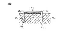
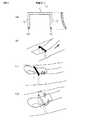
図1は、現在、手術の際に用いられている「コの字形状」を有する打ち込み式ステープルAの一例を示した図である。図1において、A1は直線状の体部、A21、A22は体部と脚部A31、A32はとの結合部、A41、A42は先端部である。FIG. 1 is a diagram showing an example of a drive-in staple A having a “U-shape” that is currently used in surgery. In FIG. 1, A1 is a linear body part, A21 and A22 are joint parts of the body part and legs A31 and A32 , and A41 and A42 are tip parts.
図2は、図1の打ち込み式ステープルAが骨10に打ち込まれた状態を示した図である。挿入抜去器で「コの字形状」のステープルAを把持し、コの字形状の2つの先端部A41、A42を骨10に打ち込み、結合部A21、A22の直前まで骨10の内部に埋め込まれている。手術終了時にステープルの体部A1は骨の外側に露出しており、直接見ることができる。FIG. 2 is a view showing a state in which the driving type staple A of FIG. 1 is driven into the
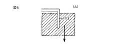
図3は、2つの骨片101、102を従来のコの字形状打ち込み式ステープルAを用いて固定した状態を示した図である。図3に示すようにステープルの脚部A31、A32が直線状であると骨片10の回転に対する固定力が弱く、図4に示すように回転力が加わると脚部A3を中心に骨片が回転しやすい。また、脚部A3と平行な方向への引っ張り力に対して骨片10と脚部A3との固定力が弱く、図5に示すように脚部A3と平行な方向に引っ張り力が加わると抜けやすい。FIG. 3 is a view showing a state in which two
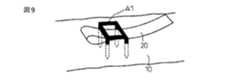
図6は、従来のコの字形状打ち込み式ステープルAを用いて、損傷を受けた又は再建された腱や靱帯20を骨10に固定した状態を示した図である。
ステープルAは、骨折や骨切りの手術において腱や靭帯を骨片に固定する際に用いられている。手術において骨に固定された損傷靱帯や損傷腱には通常引張り力が加わる。しかし、この引張り力が強いと、またはステープルの固定力が弱いと、固定された靱帯や腱が単独で若しくはステープルと共に引き抜け、または脱転するトラブルが生じてしまう。FIG. 6 is a view showing a state in which a damaged or reconstructed tendon or
The staple A is used when a tendon or a ligament is fixed to a bone fragment in a fracture or osteotomy operation. Tensile forces are usually applied to injured ligaments and injured tendons that are fixed to bone during surgery. However, when the tensile force is strong or the fixing force of the staple is weak, a trouble that the fixed ligament or tendon is pulled out or withdrawn alone or together with the staple occurs.
そこで、このようなことが生じないように図7及び図8に示されているように、靱帯や腱を折り返して1本又は複数本のステープルによって固定することが行われている。また、複数本のステープルを用いる代わりに、図9に示されているように、ステープルの体部を四角形等の多角形としたものが使われている。 Therefore, as shown in FIGS. 7 and 8, in order to prevent such a situation, the ligament or tendon is folded back and fixed with one or a plurality of staples. Further, instead of using a plurality of staples, as shown in FIG. 9, a staple body having a polygonal shape such as a square is used.
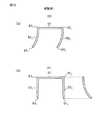
図10は、本発明の実施例1による打ち込み式ステープルBの形状を示した図である。このステープルは、直線状の体部と、該体部において所定の間隔を有した一対の結合部から相互に間隔を同じに保ったまま該直線状の体部に対して同一方向に垂直に延びている一対の脚部を備えており、該一対の脚部は該脚部の延長方向に対して垂直かつ同一方向に湾曲していることを特徴としている。 FIG. 10 is a view showing the shape of the drive-in staple B according to the first embodiment of the present invention. The staple extends vertically in the same direction with respect to the linear body part while keeping the same distance from the linear body part and a pair of coupling parts having a predetermined interval in the body part. The pair of leg portions are characterized by being curved in the same direction perpendicular to the extending direction of the leg portions.
図10(a)に示す打ち込み式ステープルBにおいて、B1は体部、B21、B22は結合部、B31、B32は脚部、B41、B42は先端部である。図10(a)に示されているように、脚部B31、B32は結合部B21、B22から相互の間隔を同じに保ったまま直線状の体部B1に対して同一方向に垂直方向に伸びており、脚部の延長方向に対して垂直かつ同一方向に湾曲している。なお、湾曲の程度及び方向は任意でよいが、湾曲の方向は同一であることが望ましい。In the drive-in staple B shown in FIG. 10A, B1 is a body part, B21 and B22 are joint parts, B31 and B32 are leg parts, and B41 and B42 are tip parts. As shown in FIG. 10 (a), the leg portions B31 and B32 are in the same direction with respect to the linear body portion B1 while maintaining the same distance from the joint portions B21 and B22. It extends in the vertical direction and is curved in the same direction perpendicular to the extending direction of the legs. The degree and direction of bending may be arbitrary, but the bending direction is preferably the same.
なお、結合部は体部の両端部に設けられているが、必ずしも体部の端部である必要はなく、端部より内側であってもよい。以下の実施例においても同様である。
図10(b)は、実施例1による打ち込み式ステープルBの正面図及び側面図である。正面から見るとコの字形であるが、側面から見ると脚部B31、B32は紙面に対して垂直方向上方に湾曲している。なお、紙面に対して下方に湾曲してもよい。このような湾曲形態は以下の実施例においても同様である。In addition, although the coupling | bond part is provided in the both ends of a body part, it does not necessarily need to be an edge part of a body part, and may be inside an edge part. The same applies to the following embodiments.
FIG. 10B is a front view and a side view of the drive-in staple B according to the first embodiment. When viewed from the front, it is U-shaped, but when viewed from the side, the legs B31 and B32 are curved upward in the vertical direction with respect to the paper surface. In addition, you may curve below with respect to a paper surface. Such a curved form is the same in the following embodiments.
図11に示すようにステープルの脚部B3が湾曲していると骨片10の回転に対する固定力が強く、図11(a)に示すように回転力が加わっても脚部B3を中心に骨片が回転しにくくなる。また、脚部B3と平行な方向への引っ張り力に対して骨片10と脚部B3との固定力が強く、図11(b)に示すように脚部B3と平行な方向に引っ張り力が加わっても抜けにくくなる。
図11(c)は、2つの骨片101と102を本発明の実施例1による打ち込み式ステープルBによって固定したときの断面図を示したものである。このように骨片101及び骨片102の両方に本発明のステープルを用いて固定すれば、回転力及び引っ張り力に対する抵抗力は相乗的に増大する。When the leg portion B3 of the staple is curved as shown in FIG. 11, the fixing force against the rotation of the
FIG. 11 (c) shows a sectional view when secured by two driving type staple B according to Example 1 of the present invention the
図12は、実施例1による打ち込み式ステープルBを用いて、損傷を受けた又は再建された腱や靱帯20を骨10に固定した状態を示した図である。
図12(a)に示すように引張り力が加わっても、脚部B31、B32が湾曲しているため骨に対する係止力が増し、固定力が増大する。靭帯や腱が矢印α方向に引っ張られた場合、ステープル脚部の先端にも矢印β方向に同様の力がかかると推察される。このときステープルの体部には矢印αと反対方向の力が働き、ステープルの挿入の度合いや湾曲具合、力のかかり具合によって、ステープル本体が矢印αと反対方向に倒れ込み、矢印γ方向に靭帯や腱を押さえようとする力が働き、固定力が増強される。FIG. 12 is a view showing a state in which a damaged or reconstructed tendon or
Even if a tensile force is applied as shown in FIG. 12 (a), since the leg portions B31 and B32 are curved, the locking force to the bone increases and the fixing force increases. When a ligament or tendon is pulled in the direction of arrow α, it is presumed that the same force is also applied in the direction of arrow β to the tips of the staple legs. At this time, a force in the direction opposite to the arrow α acts on the staple body, and the staple body falls in the opposite direction to the arrow α depending on the degree of insertion, bending, and force of the staple, and the ligament or The force to press the tendon works and the fixing force is increased.
図12(b)に示すようにステープルが矢印αで示す引張り方向に対して内側に湾曲している場合、引張り力によってステープルが倒れても脚部B31、B32が湾曲しているためステープルが浮き上がるのを防ぐことができる。靭帯や腱が矢印α方向に引っ張られた場合、ステープル脚部の先端にも矢印β方向に同様の力がかかると推察される。このときステープルの体部には矢印αと反対方向に倒れ込み、矢印γ方向に靭帯や腱を押さえようとする力が働き、固定力が増強される。
なお、図12(a)の場合、ステープルの湾曲に沿ってステープルが抜け出ようとする方向に力が作用する場合がある。しかし、固定しようとする靭帯や腱、骨にどのような力がかかるかを予測してステープルの挿入方向を選択すれば、固定力を増強することができる。
また、脚部B31、B32の方向や長さを調整することによって骨内での脚部の固定力を高めることができる。When the staple is bent inward with respect to the pulling direction indicated by the arrow α as shown in FIG. 12B, the legs B31 and B32 are bent even if the staple is tilted by the pulling force. Can be prevented from floating. When a ligament or tendon is pulled in the direction of arrow α, it is presumed that the same force is also applied in the direction of arrow β to the tips of the staple legs. At this time, the body part of the staple falls in the direction opposite to the arrow α, and a force to press the ligament or tendon acts in the direction of the arrow γ, thereby enhancing the fixing force.
In the case of FIG. 12A, a force may be applied in a direction in which the staple is about to come out along the curvature of the staple. However, if the insertion direction of the staple is selected by predicting what force is applied to the ligament, tendon, or bone to be fixed, the fixing force can be increased.
Further, it is possible to increase the fixing force of the legs in the bone by adjusting the direction and length of the leg portion B31, B32.
以下、実施例2−11について記載するが、実施例2−9についてはステープルの形状の特徴を示すことが趣旨であるため、これら実施例を示す図13−20については線でのみ示してある。なお、本願発明のステープルの体部、脚部等の断面は三角形、四角形、多角形、円形、楕円形、半円形等、どのような形状でもよい。 Hereinafter, Example 2-11 will be described. However, since Example 2-9 is intended to show the characteristics of the shape of the staple, FIGS. 13-20 showing these examples are only shown by lines. . The cross section of the body part, leg part, etc. of the staple of the present invention may be any shape such as a triangle, a quadrangle, a polygon, a circle, an ellipse, and a semicircle.
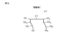
図13は、実施例1の変形で、本発明の実施例2による打ち込み式ステープルCの形状を示した図である。このステープルは脚部のうち結合部側の一部が直線状となっており、体部と直線状脚部が同一平面上でコの字形状を形成している。そして、残りの先端部側の脚部が湾曲し、この部分がコの字形状と同一平面上にないことを特徴としている。
図13に示す打ち込み式ステープルCにおいて、C1は体部、C21、C22は結合部、C31、C32は脚部、C41、C42は先端部である。そして、さらに脚部C31、C32は、脚部の直線状部の端部と前記湾曲部を接続する部分C31a、C32aを有する。FIG. 13 is a diagram showing a shape of a driving-type staple C according to a second embodiment of the present invention, which is a modification of the first embodiment. In this staple, a part of the leg part on the side of the coupling part is linear, and the body part and the linear leg part form a U-shape on the same plane. The remaining leg portion is curved, and this portion is not flush with the U-shape.
In the driven staple C shown in FIG. 13, C1 is a body part, C21 and C22 are joint parts, C31 and C32 are leg parts, and C41 and C42 are tip parts. Further, the leg portions C31 and C32 have portions C31a and C32a that connect the end portions of the linear portions of the leg portions and the curved portion.
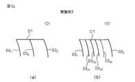
図14は、実施例1の変形で、本発明の実施例3による打ち込み式ステープルDの形状を示した図である。図14(a)に示されているように、このステープルは脚部D31と脚部D32が湾曲しており、かつ該脚部D31と脚部D32の間に更に1本の脚部D33を有している。この脚部D33は、脚部D31及び脚部D32と同様に体部D1の中間から直線状の体部D1に対して同一方向に垂直方向に伸びており、脚部D31及び脚部D32と相互に間隔を同じに保ったまま同一方向に湾曲している。なお、脚部D33と脚部D31及び脚部D32との間隔は必ずしも同じでなくてもよく、これらの中間であればよい。
なお、図14(b)に示すように、脚部D31と脚部D32の間に複数本の脚部D331〜D33nを設けてもよい。FIG. 14 is a diagram showing a shape of a driving-type staple D according to a third embodiment of the present invention, which is a modification of the first embodiment. As shown in FIG. 14 (a), the legs of the staple legs D31 and the leg D32 is curved, and further one between the legs D31 and the leg portion D32 the part D33 has. The leg D33 is extended in the same direction in a direction perpendicular to the leg D31 and leg D32 similarly to the body straight body portion D1 from the middle of the D1, legs D31 and leg part D32 and while maintaining the distance the same from each other are curved in the same direction. Incidentally, the distance between the leg portion D33 and the leg portion D31 and leg D32 may not necessarily be the same, may be any of these intermediate.
Incidentally, as shown in FIG. 14 (b), may be provided a plurality of legsD3 31to D3 3n between the legs D31 and the leg portion D32.
図15は、実施例3の変形で、本発明の実施例4による打ち込み式ステープルEの形状を示した図である。図15(a)に示されているように、このステープルは、脚部E31と脚部E32の間に更に1本の脚部E34を有し、該脚部E34は体部E1の中間から直線状の体部E1に対して同一方向に垂直方向に伸びているが、この脚部E34は湾曲しておらず直線状であり、両側の湾曲した脚部E31と脚部E32より短い。なお、脚部E34と脚部E31及び脚部E32との間隔は必ずしも同じでなくてもよく、これらの中間であればよい。
なお、この場合も、図15(b)に示すように、脚部E31と脚部E32の間に複数本の脚部E341〜E34nを設けてもよい。FIG. 15 is a diagram showing a shape of a driving-type staple E according to a fourth embodiment of the present invention, which is a modification of the third embodiment. As shown in FIG. 15 (a), the staple further includes a one leg portion E34 between the legs E31 and the leg E32, legs E34 the body portion E1 of the intermediate extend in the same direction perpendicularly to the linear body portion E1 from the leg portion E34 are linear not curved, curved leg portions on both sides E31 and the leg portion shorter than E32. Incidentally, the distance between the legs E34 and the leg portion E31 and leg E32 may not necessarily be the same, may be any of these intermediate.
Also in this case, 15 (b), the may be provided legE3 41~E34n a plurality of between the legs E31 and the leg E32.
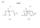
図16は、実施例1の変形で、本発明の実施例5による打ち込み式ステープルFの形状を示した図である。このステープルは脚部が湾曲しており、構成は実施例1と同じであるが、脚部の長さが異なっている点が実施例1と異なる。
図16に示す打ち込み式ステープルFにおいて、F1は体部、F21、F22は結合部、F31、F32は脚部、F41、F42は先端部である。図16に示されているように、脚部F31、F32は結合部F21、F22から直線状の体部F1に対して同一方向に垂直方向に伸びており、相互の間隔を同じに保ったまま同一方向に湾曲している。この実施例では、脚部F31とF32の長さが異なっている。なお、2つの脚部のうちどちらの脚部を短くしてもよい。FIG. 16 is a diagram showing a shape of a driving type staple F according to a fifth embodiment of the present invention, which is a modification of the first embodiment. This staple has a curved leg portion and the configuration is the same as that of the first embodiment, but differs from the first embodiment in that the length of the leg portion is different.
In the drive-in staple F shown in FIG. 16, F1 is a body part, F21 and F22 are joint parts, F31 and F32 are leg parts, and F41 and F42 are tip parts. As shown in FIG. 16, the legs F31 and F32 extend from the coupling parts F21 and F22 in the same direction perpendicular to the linear body part F1, and have the same distance from each other. And curved in the same direction. In this embodiment, different lengths of legs F31 and F32. Note that either of the two legs may be shortened.
図17は、図10に示されている実施例1の変形で、本発明の実施例6による打ち込み式ステープルGの形状を示した図である。この実施例6では、脚部の先端部G41とG42にそれぞれ枝部G41aとG42aが設けられている。
なお、先端部に枝部を設ける構成は、図13−図16に示されている実施例2−5にも適用することができる。FIG. 17 is a view showing the shape of a drive-in staple G according to a sixth embodiment of the present invention, which is a modification of the first embodiment shown in FIG. In Example 6, the leg portion of the tip G41 and G42 to branchG4 1a andG4 2a are provided respectively.
In addition, the structure which provides a branch part in a front-end | tip part is applicable also to Example 2-5 shown by FIGS. 13-16.
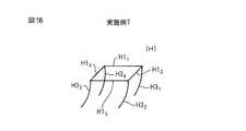
図18は、実施例7を示した図であり、体部を4本の直線状の部材により四角形に構成し、四角形の体部の各角部から該四角形の体部が形成する平面に対して同一方向に垂直に延びる4本の脚部を設けている。
図18に示す打ち込み式ステープルHにおいて、H11−H14は体部であり、四角形状となっている。四角形状の体部の角部からは、それぞれ脚部H31−H34が前記四角形の体部が形成する平面に対して相互の間隔を同じに保ったまま同一方向に垂直に延びており、該脚部は該脚部の延長方向に対して垂直かつ同一方向に湾曲している。さらに、該脚部は前記四角形状の体部を形成する直線状の部材の任意の1つ(例えば、H12)に対しても垂直方向に湾曲している。このように4本の脚部を設けることによって固定力がさらに向上する。
FIG. 18 is a diagram illustrating Example 7, in which a body part is configured to be a quadrangle by four linear members, and a plane formed by the square body part from each corner of the quadrangle body part is illustrated. Four legs extending vertically in the same direction.
In the drive-in staple H shown in FIG. 18, H11 to H14 are body parts, which have a quadrangular shape. From the corners of the quadrilateral body part, the leg parts H31 -H34 extend perpendicularly in the same direction while keeping the same distance from each other with respect to the plane formed by the quadrilateral body part, The leg portion is curved in the same direction perpendicular to the extending direction of the leg portion.Further, the leg portion iscurved in the vertical direction with respect toany one of the linear members (for example, H12)forming the rectangular body portion. Thus, fixing force is further improved by providing four legs.
図19は、実施例8を示した図であり、体部を3本の直線状の部材により三角形に構成し、三角形の体部の各角部から該三角形の体部が形成する平面に対して同一方向に垂直に延びる3本の脚部を設けている。
図19に示す打ち込み式ステープルJにおいて、J11−J13は体部であり、三角形状となっている。三角形状の体部の角部からは、それぞれ脚部H31−H33が前記三角形の体部が形成する平面に対して相互の間隔を同じに保ったまま同一方向に垂直に延びており、該脚部の延長方向に対して垂直かつ同一方向に湾曲している。さらに、該脚部は前記三角形状の体部を形成する直線状の部材の任意の1つ(例えば、J13)に対しても垂直方向に湾曲している。このように3本の脚部を設けることによって固定力がさらに向上する。
FIG. 19 is a diagram showing Example 8, in which the body part is formed into a triangle by three linear members, and the triangular body part forms a plane formed by each corner part of the triangular body part. Three legs extending vertically in the same direction.
In the drive-in type staple J shown in FIG. 19, J11 -J13 are body parts and have a triangular shape. From the corners of the triangular body part, the legs H31 -H33 extend perpendicularly in the same direction while maintaining the same distance from each other with respect to the plane formed by the triangular body part, The leg is bent in the same direction perpendicular to the extending direction of the leg.Further, the leg iscurved in the vertical direction with respect toany one of the linear members forming the triangular body (for example, J13). Thus, the fixing force is further improved by providing three legs.
図20は、実施例9を示した図であり、ステープルの脚部がテーパ状となっている。
図20に示す打ち込み式ステープルKにおいて、テーパ状の脚部は体部側から先端部側にかけて細くなっている。脚部をテーパ状とすることは、図10−図19に示された実施例1−8の脚部に適用することができる。
図20では脚部K31とK32のみテーパ状となっているが、すべての脚部又は任意の一部の脚部をテーパ状にしてもよい。FIG. 20 is a view showing Example 9, and the leg portions of the staple are tapered.
In the driving-type staple K shown in FIG. 20, the tapered leg portion is narrowed from the body portion side to the distal end portion side. Making the leg portion tapered can be applied to the leg portion of the embodiment 1-8 shown in FIGS.
Although Figure 20 the legs K31 and has a K32 only tapered, all the legs of the leg or any portion may be tapered.
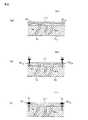
図21は、実施例10及びその効果を説明するために示した図であり、ステープル材の構造を示している。図21(a)に示す打ち込み式ステープルLにおいて、ステープル材の全部又はステープル材の一部、例えば、体部L1、脚部L31、L32、又は脚部の先端部L41、L41を中空構造としてもよい。
図21に示す構造は、図5−図19に示された実施例1−8の脚部又は先端部に適用することができる。FIG. 21 is a view for explaining the tenth embodiment and its effects, and shows the structure of the staple material. In the drive-in staple L shown in FIG. 21A, all of the staple material or a part of the staple material, for example, the body portion L1, the leg portions L31 , L32 , or the front end portions L41 , L41 of the leg portions. It may be a hollow structure.
The structure shown in FIG. 21 can be applied to the leg portion or the tip portion of Example 1-8 shown in FIGS.
図6に示す形状のステープルで靭帯や腱等を骨に固定する場合、靭帯や腱等の上からステープルを打ち込むという操作だけでは固定力が不足する場合がある。このような場合、固定した靭帯や腱等がステープルの体部との間ですべりを生じ、抜けていくという現象をきたすことがある。
このような現象を避けるため、固定する靭帯や腱等とステープルとの間の滑り止めとして、図21(b)に示すように、ステープルの体部に小さな脚部又は突起を設けることがある。同様の目的で、靭帯や腱等を折り返して糸又は細い縫合用の針金をかけて縫合することもある(図21(c))。
その場合、ステープルの体部を中空にすれば、図21(d)に示すように靭帯や腱等に糸又は細い縫合用の針金をかけた後、これら糸又は針金を中空部分に通すことができ、固定する靭帯や腱等とステープルとの間の滑り止め効果及び固定力を向上させることができる。
なお、図21(a)ではステープルの脚部を湾曲させているが、脚部を直線状にしてもよい。When a ligament, tendon, or the like is fixed to a bone with the staple having the shape shown in FIG. 6, the fixing force may be insufficient only by driving the staple from above the ligament, tendon, or the like. In such a case, a phenomenon may occur in which the fixed ligament, tendon, and the like cause slippage between the staple body parts and come off.
In order to avoid such a phenomenon, as shown in FIG. 21B, small legs or protrusions may be provided in the body of the staple as an anti-slip between the ligament or tendon to be fixed and the staple. For the same purpose, the ligaments, tendons and the like may be folded and sutured by applying a thread or a thin suture wire (FIG. 21C).
In that case, if the staple body is made hollow, as shown in FIG. 21 (d), a thread or a thin suture wire is applied to the ligament or tendon, and then the thread or wire can be passed through the hollow portion. It is possible to improve the anti-slip effect and fixing force between the ligament or tendon to be fixed and the staple.
In FIG. 21A, the leg portion of the staple is curved, but the leg portion may be linear.
図22は、実施例11を示した図であり、実施例1のステープルにおいて、体部から脚部が延びる結合部より外側に該体部が延びており、該延びた体部の端部側にスクリューが挿入できる穴が設けられている。
図22(a)に示す打ち込み式ステープルMにおいて、外側に延びた体部M1の両端にスクリュー穴M11aとM12aが設けられている。M31、M32は脚部である。
図22(b)は正面図であり、脚部M31とM32が体部M1から垂直に下方に延びている。また、外側に延びた体部M1の両端にはスクリュー穴M11aとM12aが設けられており、この穴を通してスクリューb1とb2が挿入できるようになっている。FIG. 22 is a view showing Example 11, and in the staple of Example 1, the body part extends outward from the joint part where the leg part extends from the body part, and the end part side of the extended body part Are provided with holes through which screws can be inserted.
In the drive-in staple M shown in FIG. 22A, screw holes M11a and M12a are provided at both ends of a body part M1 extending outward. M31 and M32 are legs.
Figure 22 (b) is a front view, legs M31 and M32 extends vertically downward from the body portion M1. Further, screw holes M11a and M12a are provided at both ends of the body part M1 extending outward, and the screws b1 and b2 can be inserted through these holes.
図23はスクリューにより骨片101と102を固定した従来のステープルの構造を示したものである。図23(a)は4つのスクリュー穴が設けられたステープルNで骨片101と102を固定したもので、スクリューb11、b12、b21、b22を骨片に挿入することによって骨片101と102を固定している。
しかし、図23(b)に示すように、スクリューを骨片に挿入する際に、骨折部である骨片間が固定されていないため、骨片が下方にずれてしまうことがある。また、固定した後にスクリューと平行な方向に引張り力が働くと、骨片が脱落する恐れがある。Figure 23 shows the structure of a conventional staple fixed bone fragments 101 and 102 by the screw. Figure 23 (a) is obtained by fixing the bone fragments 101 and 102 with staples N which four screw holes provided, the screwb 11, b 12, b 21 , b 22 by inserting the bone fragment securing the bone fragments 101 and 102.
However, as shown in FIG. 23 (b), when the screw is inserted into the bone fragment, the bone fragment, which is the fracture portion, is not fixed, and the bone fragment may be displaced downward. In addition, if a tensile force is applied in a direction parallel to the screw after fixing, the bone fragment may fall off.
図24は、本発明の実施例11による打ち込み式ステープル(M)を用いて2つの骨片を固定する手順と固定構造を示した図である。図24(a)に示されているように、まずステープルMの脚部M31とM32を骨片101と102に打ち込み骨間を仮定する。次に、図24(b)に示されているように、仮固定され動きを止められた骨片にスクリュー穴M11aとM12aからスクリューb1とb2を打ち込むが、脚部M31とM32が湾曲を有しているため、スクリューを打ち込む際に脚部と平行な方向に引っ張り力が加わっても骨片がずれることはない。
なお、図22に示すスクリュー穴を備えた構造は、図13−図21に示された実施例2−10の体部に適用することができる。なお、図18に示す実施例7及び図19に示す実施例8のステープルの場合、角部から外側に体部を延ばし、延びた体部の各端部側にそれぞれスクリューが挿入できる穴を設けることができる。FIG. 24 is a diagram showing a procedure and a fixing structure for fixing two bone fragments using the drive-type staple (M) according to the eleventh embodiment of the present invention. As shown in FIG. 24 (a), first, it is assumed between implanted bone legs M31 M32 staples M to the
In addition, the structure provided with the screw hole shown in FIG. 22 is applicable to the body part of Example 2-10 shown in FIGS. 13-21. In the case of the staples of Example 7 shown in FIG. 18 and Example 8 shown in FIG. 19, the body part is extended outward from the corner part, and a hole into which a screw can be inserted is provided on each end part side of the extended body part. be able to.
上記実施例1−11において、脚部の湾曲の程度は任意でよいが、各脚部が同一の曲率半径を有することが望ましい。曲率半径が同一であれば、ステープルを挿入する際に、その曲率半径に従って打ち込むようにすれば、挿入時の骨への侵襲を少なくすることができる。
なお、脚部の曲率半径は脚部全体で同じである必要はなく、例えば、脚部の上部と下部の曲率半径を異ならせてもよい。
本発明によるステープルの材質としては、チタン合金、ステンレス等、生体内に挿入されて有害でないと認められており、かつ固定力があるものであればよい。In Example 1-11, the degree of bending of the legs may be arbitrary, but it is desirable that the legs have the same radius of curvature. If the curvature radii are the same, it is possible to reduce the invasion to the bone at the time of insertion if the staples are inserted according to the curvature radii when the staples are inserted.
In addition, the curvature radius of a leg part does not need to be the same in the whole leg part, For example, you may vary the curvature radius of the upper part of a leg part, and a lower part.
The material of the staple according to the present invention may be any material such as titanium alloy, stainless steel, etc. that is recognized as not harmful when inserted into a living body and has a fixing force.
1 ステープルの体部
2 ステープルの角部
3 ステープルの脚部
4 ステープルの先端部
10 骨
20 腱、靱帯DESCRIPTION OF SYMBOLS 1 Staple body part 2 Staple corner part 3 Staple leg part 4
Claims (10)
Translated fromJapanesePriority Applications (1)
| Application Number | Priority Date | Filing Date | Title |
|---|---|---|---|
| JP2011113632AJP5159918B2 (en) | 2011-05-20 | 2011-05-20 | Medical implantable staples |
Applications Claiming Priority (1)
| Application Number | Priority Date | Filing Date | Title |
|---|---|---|---|
| JP2011113632AJP5159918B2 (en) | 2011-05-20 | 2011-05-20 | Medical implantable staples |
Related Parent Applications (1)
| Application Number | Title | Priority Date | Filing Date |
|---|---|---|---|
| JP2009054098ADivisionJP2010207289A (en) | 2009-03-06 | 2009-03-06 | Medical shooting staple |
Publications (2)
| Publication Number | Publication Date |
|---|---|
| JP2011200665A JP2011200665A (en) | 2011-10-13 |
| JP5159918B2true JP5159918B2 (en) | 2013-03-13 |
Family
ID=44878002
Family Applications (1)
| Application Number | Title | Priority Date | Filing Date |
|---|---|---|---|
| JP2011113632AActiveJP5159918B2 (en) | 2011-05-20 | 2011-05-20 | Medical implantable staples |
Country Status (1)
| Country | Link |
|---|---|
| JP (1) | JP5159918B2 (en) |
Families Citing this family (288)
| Publication number | Priority date | Publication date | Assignee | Title |
|---|---|---|---|---|
| US20070084897A1 (en) | 2003-05-20 | 2007-04-19 | Shelton Frederick E Iv | Articulating surgical stapling instrument incorporating a two-piece e-beam firing mechanism |
| US9060770B2 (en) | 2003-05-20 | 2015-06-23 | Ethicon Endo-Surgery, Inc. | Robotically-driven surgical instrument with E-beam driver |
| US9072535B2 (en) | 2011-05-27 | 2015-07-07 | Ethicon Endo-Surgery, Inc. | Surgical stapling instruments with rotatable staple deployment arrangements |
| US11890012B2 (en) | 2004-07-28 | 2024-02-06 | Cilag Gmbh International | Staple cartridge comprising cartridge body and attached support |
| US11246590B2 (en) | 2005-08-31 | 2022-02-15 | Cilag Gmbh International | Staple cartridge including staple drivers having different unfired heights |
| US7934630B2 (en) | 2005-08-31 | 2011-05-03 | Ethicon Endo-Surgery, Inc. | Staple cartridges for forming staples having differing formed staple heights |
| US11484312B2 (en) | 2005-08-31 | 2022-11-01 | Cilag Gmbh International | Staple cartridge comprising a staple driver arrangement |
| US10159482B2 (en) | 2005-08-31 | 2018-12-25 | Ethicon Llc | Fastener cartridge assembly comprising a fixed anvil and different staple heights |
| US7669746B2 (en) | 2005-08-31 | 2010-03-02 | Ethicon Endo-Surgery, Inc. | Staple cartridges for forming staples having differing formed staple heights |
| US20070106317A1 (en) | 2005-11-09 | 2007-05-10 | Shelton Frederick E Iv | Hydraulically and electrically actuated articulation joints for surgical instruments |
| US11278279B2 (en) | 2006-01-31 | 2022-03-22 | Cilag Gmbh International | Surgical instrument assembly |
| US8186555B2 (en) | 2006-01-31 | 2012-05-29 | Ethicon Endo-Surgery, Inc. | Motor-driven surgical cutting and fastening instrument with mechanical closure system |
| US11793518B2 (en) | 2006-01-31 | 2023-10-24 | Cilag Gmbh International | Powered surgical instruments with firing system lockout arrangements |
| US8820603B2 (en) | 2006-01-31 | 2014-09-02 | Ethicon Endo-Surgery, Inc. | Accessing data stored in a memory of a surgical instrument |
| US7845537B2 (en) | 2006-01-31 | 2010-12-07 | Ethicon Endo-Surgery, Inc. | Surgical instrument having recording capabilities |
| US20110295295A1 (en) | 2006-01-31 | 2011-12-01 | Ethicon Endo-Surgery, Inc. | Robotically-controlled surgical instrument having recording capabilities |
| US8708213B2 (en) | 2006-01-31 | 2014-04-29 | Ethicon Endo-Surgery, Inc. | Surgical instrument having a feedback system |
| US7753904B2 (en) | 2006-01-31 | 2010-07-13 | Ethicon Endo-Surgery, Inc. | Endoscopic surgical instrument with a handle that can articulate with respect to the shaft |
| US20120292367A1 (en) | 2006-01-31 | 2012-11-22 | Ethicon Endo-Surgery, Inc. | Robotically-controlled end effector |
| US8992422B2 (en) | 2006-03-23 | 2015-03-31 | Ethicon Endo-Surgery, Inc. | Robotically-controlled endoscopic accessory channel |
| US10568652B2 (en) | 2006-09-29 | 2020-02-25 | Ethicon Llc | Surgical staples having attached drivers of different heights and stapling instruments for deploying the same |
| US11980366B2 (en) | 2006-10-03 | 2024-05-14 | Cilag Gmbh International | Surgical instrument |
| US8632535B2 (en) | 2007-01-10 | 2014-01-21 | Ethicon Endo-Surgery, Inc. | Interlock and surgical instrument including same |
| US11291441B2 (en) | 2007-01-10 | 2022-04-05 | Cilag Gmbh International | Surgical instrument with wireless communication between control unit and remote sensor |
| US8684253B2 (en) | 2007-01-10 | 2014-04-01 | Ethicon Endo-Surgery, Inc. | Surgical instrument with wireless communication between a control unit of a robotic system and remote sensor |
| US20080169333A1 (en) | 2007-01-11 | 2008-07-17 | Shelton Frederick E | Surgical stapler end effector with tapered distal end |
| US7673782B2 (en) | 2007-03-15 | 2010-03-09 | Ethicon Endo-Surgery, Inc. | Surgical stapling instrument having a releasable buttress material |
| US8931682B2 (en) | 2007-06-04 | 2015-01-13 | Ethicon Endo-Surgery, Inc. | Robotically-controlled shaft based rotary drive systems for surgical instruments |
| US11564682B2 (en) | 2007-06-04 | 2023-01-31 | Cilag Gmbh International | Surgical stapler device |
| US7753245B2 (en) | 2007-06-22 | 2010-07-13 | Ethicon Endo-Surgery, Inc. | Surgical stapling instruments |
| US11849941B2 (en) | 2007-06-29 | 2023-12-26 | Cilag Gmbh International | Staple cartridge having staple cavities extending at a transverse angle relative to a longitudinal cartridge axis |
| US9179912B2 (en) | 2008-02-14 | 2015-11-10 | Ethicon Endo-Surgery, Inc. | Robotically-controlled motorized surgical cutting and fastening instrument |
| JP5410110B2 (en) | 2008-02-14 | 2014-02-05 | エシコン・エンド−サージェリィ・インコーポレイテッド | Surgical cutting / fixing instrument with RF electrode |
| US11986183B2 (en) | 2008-02-14 | 2024-05-21 | Cilag Gmbh International | Surgical cutting and fastening instrument comprising a plurality of sensors to measure an electrical parameter |
| US8573465B2 (en) | 2008-02-14 | 2013-11-05 | Ethicon Endo-Surgery, Inc. | Robotically-controlled surgical end effector system with rotary actuated closure systems |
| US7866527B2 (en) | 2008-02-14 | 2011-01-11 | Ethicon Endo-Surgery, Inc. | Surgical stapling apparatus with interlockable firing system |
| US8636736B2 (en) | 2008-02-14 | 2014-01-28 | Ethicon Endo-Surgery, Inc. | Motorized surgical cutting and fastening instrument |
| US7819298B2 (en) | 2008-02-14 | 2010-10-26 | Ethicon Endo-Surgery, Inc. | Surgical stapling apparatus with control features operable with one hand |
| US9585657B2 (en) | 2008-02-15 | 2017-03-07 | Ethicon Endo-Surgery, Llc | Actuator for releasing a layer of material from a surgical end effector |
| US11648005B2 (en) | 2008-09-23 | 2023-05-16 | Cilag Gmbh International | Robotically-controlled motorized surgical instrument with an end effector |
| US8210411B2 (en) | 2008-09-23 | 2012-07-03 | Ethicon Endo-Surgery, Inc. | Motor-driven surgical cutting instrument |
| US9386983B2 (en) | 2008-09-23 | 2016-07-12 | Ethicon Endo-Surgery, Llc | Robotically-controlled motorized surgical instrument |
| US9005230B2 (en) | 2008-09-23 | 2015-04-14 | Ethicon Endo-Surgery, Inc. | Motorized surgical instrument |
| US8608045B2 (en) | 2008-10-10 | 2013-12-17 | Ethicon Endo-Sugery, Inc. | Powered surgical cutting and stapling apparatus with manually retractable firing system |
| US8220688B2 (en) | 2009-12-24 | 2012-07-17 | Ethicon Endo-Surgery, Inc. | Motor-driven surgical cutting instrument with electric actuator directional control assembly |
| US8783543B2 (en) | 2010-07-30 | 2014-07-22 | Ethicon Endo-Surgery, Inc. | Tissue acquisition arrangements and methods for surgical stapling devices |
| US11925354B2 (en) | 2010-09-30 | 2024-03-12 | Cilag Gmbh International | Staple cartridge comprising staples positioned within a compressible portion thereof |
| US9788834B2 (en) | 2010-09-30 | 2017-10-17 | Ethicon Llc | Layer comprising deployable attachment members |
| US9016542B2 (en) | 2010-09-30 | 2015-04-28 | Ethicon Endo-Surgery, Inc. | Staple cartridge comprising compressible distortion resistant components |
| US10945731B2 (en) | 2010-09-30 | 2021-03-16 | Ethicon Llc | Tissue thickness compensator comprising controlled release and expansion |
| US12213666B2 (en) | 2010-09-30 | 2025-02-04 | Cilag Gmbh International | Tissue thickness compensator comprising layers |
| US9386988B2 (en) | 2010-09-30 | 2016-07-12 | Ethicon End-Surgery, LLC | Retainer assembly including a tissue thickness compensator |
| US11812965B2 (en) | 2010-09-30 | 2023-11-14 | Cilag Gmbh International | Layer of material for a surgical end effector |
| US11298125B2 (en) | 2010-09-30 | 2022-04-12 | Cilag Gmbh International | Tissue stapler having a thickness compensator |
| US9351730B2 (en) | 2011-04-29 | 2016-05-31 | Ethicon Endo-Surgery, Llc | Tissue thickness compensator comprising channels |
| US9629814B2 (en) | 2010-09-30 | 2017-04-25 | Ethicon Endo-Surgery, Llc | Tissue thickness compensator configured to redistribute compressive forces |
| US8695866B2 (en) | 2010-10-01 | 2014-04-15 | Ethicon Endo-Surgery, Inc. | Surgical instrument having a power control circuit |
| AU2012250197B2 (en) | 2011-04-29 | 2017-08-10 | Ethicon Endo-Surgery, Inc. | Staple cartridge comprising staples positioned within a compressible portion thereof |
| US11207064B2 (en) | 2011-05-27 | 2021-12-28 | Cilag Gmbh International | Automated end effector component reloading system for use with a robotic system |
| MX358135B (en) | 2012-03-28 | 2018-08-06 | Ethicon Endo Surgery Inc | Tissue thickness compensator comprising a plurality of layers. |
| BR112014024098B1 (en) | 2012-03-28 | 2021-05-25 | Ethicon Endo-Surgery, Inc. | staple cartridge |
| US9101358B2 (en) | 2012-06-15 | 2015-08-11 | Ethicon Endo-Surgery, Inc. | Articulatable surgical instrument comprising a firing drive |
| BR112014032776B1 (en) | 2012-06-28 | 2021-09-08 | Ethicon Endo-Surgery, Inc | SURGICAL INSTRUMENT SYSTEM AND SURGICAL KIT FOR USE WITH A SURGICAL INSTRUMENT SYSTEM |
| US9282974B2 (en) | 2012-06-28 | 2016-03-15 | Ethicon Endo-Surgery, Llc | Empty clip cartridge lockout |
| US9408606B2 (en) | 2012-06-28 | 2016-08-09 | Ethicon Endo-Surgery, Llc | Robotically powered surgical device with manually-actuatable reversing system |
| US20140001231A1 (en) | 2012-06-28 | 2014-01-02 | Ethicon Endo-Surgery, Inc. | Firing system lockout arrangements for surgical instruments |
| US12383267B2 (en) | 2012-06-28 | 2025-08-12 | Cilag Gmbh International | Robotically powered surgical device with manually-actuatable reversing system |
| US9289256B2 (en) | 2012-06-28 | 2016-03-22 | Ethicon Endo-Surgery, Llc | Surgical end effectors having angled tissue-contacting surfaces |
| RU2672520C2 (en) | 2013-03-01 | 2018-11-15 | Этикон Эндо-Серджери, Инк. | Hingedly turnable surgical instruments with conducting ways for signal transfer |
| BR112015021082B1 (en) | 2013-03-01 | 2022-05-10 | Ethicon Endo-Surgery, Inc | surgical instrument |
| US9629629B2 (en) | 2013-03-14 | 2017-04-25 | Ethicon Endo-Surgey, LLC | Control systems for surgical instruments |
| BR112015026109B1 (en) | 2013-04-16 | 2022-02-22 | Ethicon Endo-Surgery, Inc | surgical instrument |
| US9826976B2 (en) | 2013-04-16 | 2017-11-28 | Ethicon Llc | Motor driven surgical instruments with lockable dual drive shafts |
| US9775609B2 (en) | 2013-08-23 | 2017-10-03 | Ethicon Llc | Tamper proof circuit for surgical instrument battery pack |
| MX369362B (en) | 2013-08-23 | 2019-11-06 | Ethicon Endo Surgery Llc | Firing member retraction devices for powered surgical instruments. |
| US10013049B2 (en) | 2014-03-26 | 2018-07-03 | Ethicon Llc | Power management through sleep options of segmented circuit and wake up control |
| BR112016021943B1 (en) | 2014-03-26 | 2022-06-14 | Ethicon Endo-Surgery, Llc | SURGICAL INSTRUMENT FOR USE BY AN OPERATOR IN A SURGICAL PROCEDURE |
| US20150272580A1 (en) | 2014-03-26 | 2015-10-01 | Ethicon Endo-Surgery, Inc. | Verification of number of battery exchanges/procedure count |
| US12232723B2 (en) | 2014-03-26 | 2025-02-25 | Cilag Gmbh International | Systems and methods for controlling a segmented circuit |
| US10327764B2 (en) | 2014-09-26 | 2019-06-25 | Ethicon Llc | Method for creating a flexible staple line |
| BR112016023825B1 (en) | 2014-04-16 | 2022-08-02 | Ethicon Endo-Surgery, Llc | STAPLE CARTRIDGE FOR USE WITH A SURGICAL STAPLER AND STAPLE CARTRIDGE FOR USE WITH A SURGICAL INSTRUMENT |
| CN106456176B (en) | 2014-04-16 | 2019-06-28 | 伊西康内外科有限责任公司 | Fastener Cartridge Including Extensions With Different Configurations |
| CN106456159B (en) | 2014-04-16 | 2019-03-08 | 伊西康内外科有限责任公司 | Fastener Cartridge Assembly and Nail Retainer Cover Arrangement |
| US20150297225A1 (en) | 2014-04-16 | 2015-10-22 | Ethicon Endo-Surgery, Inc. | Fastener cartridges including extensions having different configurations |
| BR112017004361B1 (en) | 2014-09-05 | 2023-04-11 | Ethicon Llc | ELECTRONIC SYSTEM FOR A SURGICAL INSTRUMENT |
| US11311294B2 (en) | 2014-09-05 | 2022-04-26 | Cilag Gmbh International | Powered medical device including measurement of closure state of jaws |
| US10135242B2 (en) | 2014-09-05 | 2018-11-20 | Ethicon Llc | Smart cartridge wake up operation and data retention |
| US10105142B2 (en) | 2014-09-18 | 2018-10-23 | Ethicon Llc | Surgical stapler with plurality of cutting elements |
| US11523821B2 (en) | 2014-09-26 | 2022-12-13 | Cilag Gmbh International | Method for creating a flexible staple line |
| US9924944B2 (en) | 2014-10-16 | 2018-03-27 | Ethicon Llc | Staple cartridge comprising an adjunct material |
| US10517594B2 (en) | 2014-10-29 | 2019-12-31 | Ethicon Llc | Cartridge assemblies for surgical staplers |
| US11141153B2 (en) | 2014-10-29 | 2021-10-12 | Cilag Gmbh International | Staple cartridges comprising driver arrangements |
| US9844376B2 (en) | 2014-11-06 | 2017-12-19 | Ethicon Llc | Staple cartridge comprising a releasable adjunct material |
| US10736636B2 (en) | 2014-12-10 | 2020-08-11 | Ethicon Llc | Articulatable surgical instrument system |
| MX389118B (en) | 2014-12-18 | 2025-03-20 | Ethicon Llc | SURGICAL INSTRUMENT WITH AN ANVIL THAT CAN BE SELECTIVELY MOVED ON A DISCRETE, NON-MOBILE AXIS RELATIVE TO A STAPLE CARTRIDGE. |
| US9844374B2 (en) | 2014-12-18 | 2017-12-19 | Ethicon Llc | Surgical instrument systems comprising an articulatable end effector and means for adjusting the firing stroke of a firing member |
| US9943309B2 (en) | 2014-12-18 | 2018-04-17 | Ethicon Llc | Surgical instruments with articulatable end effectors and movable firing beam support arrangements |
| US10085748B2 (en) | 2014-12-18 | 2018-10-02 | Ethicon Llc | Locking arrangements for detachable shaft assemblies with articulatable surgical end effectors |
| US9844375B2 (en) | 2014-12-18 | 2017-12-19 | Ethicon Llc | Drive arrangements for articulatable surgical instruments |
| US9987000B2 (en) | 2014-12-18 | 2018-06-05 | Ethicon Llc | Surgical instrument assembly comprising a flexible articulation system |
| US11154301B2 (en) | 2015-02-27 | 2021-10-26 | Cilag Gmbh International | Modular stapling assembly |
| JP2020121162A (en) | 2015-03-06 | 2020-08-13 | エシコン エルエルシーEthicon LLC | Time dependent evaluation of sensor data to determine stability element, creep element and viscoelastic element of measurement |
| US9993248B2 (en) | 2015-03-06 | 2018-06-12 | Ethicon Endo-Surgery, Llc | Smart sensors with local signal processing |
| US10441279B2 (en) | 2015-03-06 | 2019-10-15 | Ethicon Llc | Multiple level thresholds to modify operation of powered surgical instruments |
| US10548504B2 (en) | 2015-03-06 | 2020-02-04 | Ethicon Llc | Overlaid multi sensor radio frequency (RF) electrode system to measure tissue compression |
| US10433844B2 (en) | 2015-03-31 | 2019-10-08 | Ethicon Llc | Surgical instrument with selectively disengageable threaded drive systems |
| US10105139B2 (en) | 2015-09-23 | 2018-10-23 | Ethicon Llc | Surgical stapler having downstream current-based motor control |
| US10238386B2 (en) | 2015-09-23 | 2019-03-26 | Ethicon Llc | Surgical stapler having motor control based on an electrical parameter related to a motor current |
| US10299878B2 (en) | 2015-09-25 | 2019-05-28 | Ethicon Llc | Implantable adjunct systems for determining adjunct skew |
| US11890015B2 (en) | 2015-09-30 | 2024-02-06 | Cilag Gmbh International | Compressible adjunct with crossing spacer fibers |
| US10478188B2 (en) | 2015-09-30 | 2019-11-19 | Ethicon Llc | Implantable layer comprising a constricted configuration |
| US10433846B2 (en) | 2015-09-30 | 2019-10-08 | Ethicon Llc | Compressible adjunct with crossing spacer fibers |
| US10772632B2 (en)* | 2015-10-28 | 2020-09-15 | Covidien Lp | Surgical stapling device with triple leg staples |
| US10265068B2 (en) | 2015-12-30 | 2019-04-23 | Ethicon Llc | Surgical instruments with separable motors and motor control circuits |
| US10292704B2 (en) | 2015-12-30 | 2019-05-21 | Ethicon Llc | Mechanisms for compensating for battery pack failure in powered surgical instruments |
| BR112018016098B1 (en) | 2016-02-09 | 2023-02-23 | Ethicon Llc | SURGICAL INSTRUMENT |
| US11213293B2 (en) | 2016-02-09 | 2022-01-04 | Cilag Gmbh International | Articulatable surgical instruments with single articulation link arrangements |
| US10448948B2 (en) | 2016-02-12 | 2019-10-22 | Ethicon Llc | Mechanisms for compensating for drivetrain failure in powered surgical instruments |
| US11224426B2 (en) | 2016-02-12 | 2022-01-18 | Cilag Gmbh International | Mechanisms for compensating for drivetrain failure in powered surgical instruments |
| US10828028B2 (en) | 2016-04-15 | 2020-11-10 | Ethicon Llc | Surgical instrument with multiple program responses during a firing motion |
| US10426467B2 (en) | 2016-04-15 | 2019-10-01 | Ethicon Llc | Surgical instrument with detection sensors |
| US11607239B2 (en) | 2016-04-15 | 2023-03-21 | Cilag Gmbh International | Systems and methods for controlling a surgical stapling and cutting instrument |
| US10492783B2 (en) | 2016-04-15 | 2019-12-03 | Ethicon, Llc | Surgical instrument with improved stop/start control during a firing motion |
| US10357247B2 (en) | 2016-04-15 | 2019-07-23 | Ethicon Llc | Surgical instrument with multiple program responses during a firing motion |
| US20170296173A1 (en) | 2016-04-18 | 2017-10-19 | Ethicon Endo-Surgery, Llc | Method for operating a surgical instrument |
| US10363037B2 (en) | 2016-04-18 | 2019-07-30 | Ethicon Llc | Surgical instrument system comprising a magnetic lockout |
| US11317917B2 (en) | 2016-04-18 | 2022-05-03 | Cilag Gmbh International | Surgical stapling system comprising a lockable firing assembly |
| US10500000B2 (en) | 2016-08-16 | 2019-12-10 | Ethicon Llc | Surgical tool with manual control of end effector jaws |
| JP6983893B2 (en) | 2016-12-21 | 2021-12-17 | エシコン エルエルシーEthicon LLC | Lockout configuration for surgical end effectors and replaceable tool assemblies |
| US10973516B2 (en) | 2016-12-21 | 2021-04-13 | Ethicon Llc | Surgical end effectors and adaptable firing members therefor |
| US11419606B2 (en) | 2016-12-21 | 2022-08-23 | Cilag Gmbh International | Shaft assembly comprising a clutch configured to adapt the output of a rotary firing member to two different systems |
| JP7010956B2 (en) | 2016-12-21 | 2022-01-26 | エシコン エルエルシー | How to staple tissue |
| US11090048B2 (en) | 2016-12-21 | 2021-08-17 | Cilag Gmbh International | Method for resetting a fuse of a surgical instrument shaft |
| US10813638B2 (en) | 2016-12-21 | 2020-10-27 | Ethicon Llc | Surgical end effectors with expandable tissue stop arrangements |
| JP2020501815A (en) | 2016-12-21 | 2020-01-23 | エシコン エルエルシーEthicon LLC | Surgical stapling system |
| US20180168625A1 (en) | 2016-12-21 | 2018-06-21 | Ethicon Endo-Surgery, Llc | Surgical stapling instruments with smart staple cartridges |
| US10542982B2 (en) | 2016-12-21 | 2020-01-28 | Ethicon Llc | Shaft assembly comprising first and second articulation lockouts |
| JP7010957B2 (en) | 2016-12-21 | 2022-01-26 | エシコン エルエルシー | Shaft assembly with lockout |
| US10582928B2 (en) | 2016-12-21 | 2020-03-10 | Ethicon Llc | Articulation lock arrangements for locking an end effector in an articulated position in response to actuation of a jaw closure system |
| MX2019007295A (en) | 2016-12-21 | 2019-10-15 | Ethicon Llc | Surgical instrument system comprising an end effector lockout and a firing assembly lockout. |
| US20180168615A1 (en) | 2016-12-21 | 2018-06-21 | Ethicon Endo-Surgery, Llc | Method of deforming staples from two different types of staple cartridges with the same surgical stapling instrument |
| US11517325B2 (en) | 2017-06-20 | 2022-12-06 | Cilag Gmbh International | Closed loop feedback control of motor velocity of a surgical stapling and cutting instrument based on measured displacement distance traveled over a specified time interval |
| US10779820B2 (en) | 2017-06-20 | 2020-09-22 | Ethicon Llc | Systems and methods for controlling motor speed according to user input for a surgical instrument |
| US10307170B2 (en) | 2017-06-20 | 2019-06-04 | Ethicon Llc | Method for closed loop control of motor velocity of a surgical stapling and cutting instrument |
| US10881399B2 (en) | 2017-06-20 | 2021-01-05 | Ethicon Llc | Techniques for adaptive control of motor velocity of a surgical stapling and cutting instrument |
| US11382638B2 (en) | 2017-06-20 | 2022-07-12 | Cilag Gmbh International | Closed loop feedback control of motor velocity of a surgical stapling and cutting instrument based on measured time over a specified displacement distance |
| US11653914B2 (en) | 2017-06-20 | 2023-05-23 | Cilag Gmbh International | Systems and methods for controlling motor velocity of a surgical stapling and cutting instrument according to articulation angle of end effector |
| US11324503B2 (en) | 2017-06-27 | 2022-05-10 | Cilag Gmbh International | Surgical firing member arrangements |
| US11266405B2 (en) | 2017-06-27 | 2022-03-08 | Cilag Gmbh International | Surgical anvil manufacturing methods |
| US10993716B2 (en) | 2017-06-27 | 2021-05-04 | Ethicon Llc | Surgical anvil arrangements |
| EP3420947B1 (en) | 2017-06-28 | 2022-05-25 | Cilag GmbH International | Surgical instrument comprising selectively actuatable rotatable couplers |
| USD906355S1 (en) | 2017-06-28 | 2020-12-29 | Ethicon Llc | Display screen or portion thereof with a graphical user interface for a surgical instrument |
| US10758232B2 (en) | 2017-06-28 | 2020-09-01 | Ethicon Llc | Surgical instrument with positive jaw opening features |
| US10765427B2 (en) | 2017-06-28 | 2020-09-08 | Ethicon Llc | Method for articulating a surgical instrument |
| US11564686B2 (en) | 2017-06-28 | 2023-01-31 | Cilag Gmbh International | Surgical shaft assemblies with flexible interfaces |
| US11484310B2 (en) | 2017-06-28 | 2022-11-01 | Cilag Gmbh International | Surgical instrument comprising a shaft including a closure tube profile |
| US10932772B2 (en) | 2017-06-29 | 2021-03-02 | Ethicon Llc | Methods for closed loop velocity control for robotic surgical instrument |
| US11944300B2 (en) | 2017-08-03 | 2024-04-02 | Cilag Gmbh International | Method for operating a surgical system bailout |
| US11974742B2 (en) | 2017-08-03 | 2024-05-07 | Cilag Gmbh International | Surgical system comprising an articulation bailout |
| US11471155B2 (en) | 2017-08-03 | 2022-10-18 | Cilag Gmbh International | Surgical system bailout |
| US11304695B2 (en) | 2017-08-03 | 2022-04-19 | Cilag Gmbh International | Surgical system shaft interconnection |
| US10743872B2 (en) | 2017-09-29 | 2020-08-18 | Ethicon Llc | System and methods for controlling a display of a surgical instrument |
| US11134944B2 (en) | 2017-10-30 | 2021-10-05 | Cilag Gmbh International | Surgical stapler knife motion controls |
| US10842490B2 (en) | 2017-10-31 | 2020-11-24 | Ethicon Llc | Cartridge body design with force reduction based on firing completion |
| US10779826B2 (en) | 2017-12-15 | 2020-09-22 | Ethicon Llc | Methods of operating surgical end effectors |
| US10835330B2 (en) | 2017-12-19 | 2020-11-17 | Ethicon Llc | Method for determining the position of a rotatable jaw of a surgical instrument attachment assembly |
| US12336705B2 (en) | 2017-12-21 | 2025-06-24 | Cilag Gmbh International | Continuous use self-propelled stapling instrument |
| US11311290B2 (en) | 2017-12-21 | 2022-04-26 | Cilag Gmbh International | Surgical instrument comprising an end effector dampener |
| US11179151B2 (en) | 2017-12-21 | 2021-11-23 | Cilag Gmbh International | Surgical instrument comprising a display |
| US11324501B2 (en) | 2018-08-20 | 2022-05-10 | Cilag Gmbh International | Surgical stapling devices with improved closure members |
| US11291440B2 (en) | 2018-08-20 | 2022-04-05 | Cilag Gmbh International | Method for operating a powered articulatable surgical instrument |
| US20200054321A1 (en) | 2018-08-20 | 2020-02-20 | Ethicon Llc | Surgical instruments with progressive jaw closure arrangements |
| US11207065B2 (en) | 2018-08-20 | 2021-12-28 | Cilag Gmbh International | Method for fabricating surgical stapler anvils |
| US11696761B2 (en) | 2019-03-25 | 2023-07-11 | Cilag Gmbh International | Firing drive arrangements for surgical systems |
| US11253254B2 (en) | 2019-04-30 | 2022-02-22 | Cilag Gmbh International | Shaft rotation actuator on a surgical instrument |
| US11452528B2 (en) | 2019-04-30 | 2022-09-27 | Cilag Gmbh International | Articulation actuators for a surgical instrument |
| US11648009B2 (en) | 2019-04-30 | 2023-05-16 | Cilag Gmbh International | Rotatable jaw tip for a surgical instrument |
| US11426251B2 (en) | 2019-04-30 | 2022-08-30 | Cilag Gmbh International | Articulation directional lights on a surgical instrument |
| US11432816B2 (en) | 2019-04-30 | 2022-09-06 | Cilag Gmbh International | Articulation pin for a surgical instrument |
| US11471157B2 (en) | 2019-04-30 | 2022-10-18 | Cilag Gmbh International | Articulation control mapping for a surgical instrument |
| US11903581B2 (en) | 2019-04-30 | 2024-02-20 | Cilag Gmbh International | Methods for stapling tissue using a surgical instrument |
| US12004740B2 (en) | 2019-06-28 | 2024-06-11 | Cilag Gmbh International | Surgical stapling system having an information decryption protocol |
| US11376098B2 (en) | 2019-06-28 | 2022-07-05 | Cilag Gmbh International | Surgical instrument system comprising an RFID system |
| US11464601B2 (en) | 2019-06-28 | 2022-10-11 | Cilag Gmbh International | Surgical instrument comprising an RFID system for tracking a movable component |
| US11361176B2 (en) | 2019-06-28 | 2022-06-14 | Cilag Gmbh International | Surgical RFID assemblies for compatibility detection |
| US11523822B2 (en) | 2019-06-28 | 2022-12-13 | Cilag Gmbh International | Battery pack including a circuit interrupter |
| US11684434B2 (en) | 2019-06-28 | 2023-06-27 | Cilag Gmbh International | Surgical RFID assemblies for instrument operational setting control |
| US11399837B2 (en) | 2019-06-28 | 2022-08-02 | Cilag Gmbh International | Mechanisms for motor control adjustments of a motorized surgical instrument |
| US11478241B2 (en) | 2019-06-28 | 2022-10-25 | Cilag Gmbh International | Staple cartridge including projections |
| US11497492B2 (en) | 2019-06-28 | 2022-11-15 | Cilag Gmbh International | Surgical instrument including an articulation lock |
| US11638587B2 (en) | 2019-06-28 | 2023-05-02 | Cilag Gmbh International | RFID identification systems for surgical instruments |
| US11298127B2 (en) | 2019-06-28 | 2022-04-12 | Cilag GmbH Interational | Surgical stapling system having a lockout mechanism for an incompatible cartridge |
| US11291451B2 (en) | 2019-06-28 | 2022-04-05 | Cilag Gmbh International | Surgical instrument with battery compatibility verification functionality |
| US11627959B2 (en) | 2019-06-28 | 2023-04-18 | Cilag Gmbh International | Surgical instruments including manual and powered system lockouts |
| US11853835B2 (en) | 2019-06-28 | 2023-12-26 | Cilag Gmbh International | RFID identification systems for surgical instruments |
| US11660163B2 (en) | 2019-06-28 | 2023-05-30 | Cilag Gmbh International | Surgical system with RFID tags for updating motor assembly parameters |
| US11426167B2 (en) | 2019-06-28 | 2022-08-30 | Cilag Gmbh International | Mechanisms for proper anvil attachment surgical stapling head assembly |
| US11298132B2 (en) | 2019-06-28 | 2022-04-12 | Cilag GmbH Inlernational | Staple cartridge including a honeycomb extension |
| US11771419B2 (en) | 2019-06-28 | 2023-10-03 | Cilag Gmbh International | Packaging for a replaceable component of a surgical stapling system |
| US11553971B2 (en) | 2019-06-28 | 2023-01-17 | Cilag Gmbh International | Surgical RFID assemblies for display and communication |
| US11241235B2 (en) | 2019-06-28 | 2022-02-08 | Cilag Gmbh International | Method of using multiple RFID chips with a surgical assembly |
| US11576672B2 (en) | 2019-12-19 | 2023-02-14 | Cilag Gmbh International | Surgical instrument comprising a closure system including a closure member and an opening member driven by a drive screw |
| US11304696B2 (en) | 2019-12-19 | 2022-04-19 | Cilag Gmbh International | Surgical instrument comprising a powered articulation system |
| US11911032B2 (en) | 2019-12-19 | 2024-02-27 | Cilag Gmbh International | Staple cartridge comprising a seating cam |
| US11607219B2 (en) | 2019-12-19 | 2023-03-21 | Cilag Gmbh International | Staple cartridge comprising a detachable tissue cutting knife |
| US11446029B2 (en) | 2019-12-19 | 2022-09-20 | Cilag Gmbh International | Staple cartridge comprising projections extending from a curved deck surface |
| US11701111B2 (en) | 2019-12-19 | 2023-07-18 | Cilag Gmbh International | Method for operating a surgical stapling instrument |
| US11844520B2 (en) | 2019-12-19 | 2023-12-19 | Cilag Gmbh International | Staple cartridge comprising driver retention members |
| US11529137B2 (en) | 2019-12-19 | 2022-12-20 | Cilag Gmbh International | Staple cartridge comprising driver retention members |
| US11464512B2 (en) | 2019-12-19 | 2022-10-11 | Cilag Gmbh International | Staple cartridge comprising a curved deck surface |
| US11559304B2 (en) | 2019-12-19 | 2023-01-24 | Cilag Gmbh International | Surgical instrument comprising a rapid closure mechanism |
| US11291447B2 (en) | 2019-12-19 | 2022-04-05 | Cilag Gmbh International | Stapling instrument comprising independent jaw closing and staple firing systems |
| US12035913B2 (en) | 2019-12-19 | 2024-07-16 | Cilag Gmbh International | Staple cartridge comprising a deployable knife |
| US11529139B2 (en) | 2019-12-19 | 2022-12-20 | Cilag Gmbh International | Motor driven surgical instrument |
| US11504122B2 (en) | 2019-12-19 | 2022-11-22 | Cilag Gmbh International | Surgical instrument comprising a nested firing member |
| USD974560S1 (en) | 2020-06-02 | 2023-01-03 | Cilag Gmbh International | Staple cartridge |
| USD967421S1 (en) | 2020-06-02 | 2022-10-18 | Cilag Gmbh International | Staple cartridge |
| USD975278S1 (en) | 2020-06-02 | 2023-01-10 | Cilag Gmbh International | Staple cartridge |
| USD975850S1 (en) | 2020-06-02 | 2023-01-17 | Cilag Gmbh International | Staple cartridge |
| USD976401S1 (en) | 2020-06-02 | 2023-01-24 | Cilag Gmbh International | Staple cartridge |
| USD975851S1 (en) | 2020-06-02 | 2023-01-17 | Cilag Gmbh International | Staple cartridge |
| USD966512S1 (en) | 2020-06-02 | 2022-10-11 | Cilag Gmbh International | Staple cartridge |
| US11871925B2 (en) | 2020-07-28 | 2024-01-16 | Cilag Gmbh International | Surgical instruments with dual spherical articulation joint arrangements |
| US11779330B2 (en) | 2020-10-29 | 2023-10-10 | Cilag Gmbh International | Surgical instrument comprising a jaw alignment system |
| US11452526B2 (en) | 2020-10-29 | 2022-09-27 | Cilag Gmbh International | Surgical instrument comprising a staged voltage regulation start-up system |
| US11617577B2 (en) | 2020-10-29 | 2023-04-04 | Cilag Gmbh International | Surgical instrument comprising a sensor configured to sense whether an articulation drive of the surgical instrument is actuatable |
| US11931025B2 (en) | 2020-10-29 | 2024-03-19 | Cilag Gmbh International | Surgical instrument comprising a releasable closure drive lock |
| US11844518B2 (en) | 2020-10-29 | 2023-12-19 | Cilag Gmbh International | Method for operating a surgical instrument |
| US11896217B2 (en) | 2020-10-29 | 2024-02-13 | Cilag Gmbh International | Surgical instrument comprising an articulation lock |
| USD1013170S1 (en) | 2020-10-29 | 2024-01-30 | Cilag Gmbh International | Surgical instrument assembly |
| US11717289B2 (en) | 2020-10-29 | 2023-08-08 | Cilag Gmbh International | Surgical instrument comprising an indicator which indicates that an articulation drive is actuatable |
| US11534259B2 (en) | 2020-10-29 | 2022-12-27 | Cilag Gmbh International | Surgical instrument comprising an articulation indicator |
| US12053175B2 (en) | 2020-10-29 | 2024-08-06 | Cilag Gmbh International | Surgical instrument comprising a stowed closure actuator stop |
| USD980425S1 (en) | 2020-10-29 | 2023-03-07 | Cilag Gmbh International | Surgical instrument assembly |
| US11517390B2 (en) | 2020-10-29 | 2022-12-06 | Cilag Gmbh International | Surgical instrument comprising a limited travel switch |
| US11944296B2 (en) | 2020-12-02 | 2024-04-02 | Cilag Gmbh International | Powered surgical instruments with external connectors |
| US11627960B2 (en) | 2020-12-02 | 2023-04-18 | Cilag Gmbh International | Powered surgical instruments with smart reload with separately attachable exteriorly mounted wiring connections |
| US11744581B2 (en) | 2020-12-02 | 2023-09-05 | Cilag Gmbh International | Powered surgical instruments with multi-phase tissue treatment |
| US11653915B2 (en) | 2020-12-02 | 2023-05-23 | Cilag Gmbh International | Surgical instruments with sled location detection and adjustment features |
| US11890010B2 (en) | 2020-12-02 | 2024-02-06 | Cllag GmbH International | Dual-sided reinforced reload for surgical instruments |
| US11737751B2 (en) | 2020-12-02 | 2023-08-29 | Cilag Gmbh International | Devices and methods of managing energy dissipated within sterile barriers of surgical instrument housings |
| US11653920B2 (en) | 2020-12-02 | 2023-05-23 | Cilag Gmbh International | Powered surgical instruments with communication interfaces through sterile barrier |
| US11849943B2 (en) | 2020-12-02 | 2023-12-26 | Cilag Gmbh International | Surgical instrument with cartridge release mechanisms |
| US11678882B2 (en) | 2020-12-02 | 2023-06-20 | Cilag Gmbh International | Surgical instruments with interactive features to remedy incidental sled movements |
| US11696757B2 (en) | 2021-02-26 | 2023-07-11 | Cilag Gmbh International | Monitoring of internal systems to detect and track cartridge motion status |
| US11812964B2 (en) | 2021-02-26 | 2023-11-14 | Cilag Gmbh International | Staple cartridge comprising a power management circuit |
| US11950777B2 (en) | 2021-02-26 | 2024-04-09 | Cilag Gmbh International | Staple cartridge comprising an information access control system |
| US11925349B2 (en) | 2021-02-26 | 2024-03-12 | Cilag Gmbh International | Adjustment to transfer parameters to improve available power |
| US11744583B2 (en) | 2021-02-26 | 2023-09-05 | Cilag Gmbh International | Distal communication array to tune frequency of RF systems |
| US12324580B2 (en) | 2021-02-26 | 2025-06-10 | Cilag Gmbh International | Method of powering and communicating with a staple cartridge |
| US12108951B2 (en) | 2021-02-26 | 2024-10-08 | Cilag Gmbh International | Staple cartridge comprising a sensing array and a temperature control system |
| US11950779B2 (en) | 2021-02-26 | 2024-04-09 | Cilag Gmbh International | Method of powering and communicating with a staple cartridge |
| US11730473B2 (en) | 2021-02-26 | 2023-08-22 | Cilag Gmbh International | Monitoring of manufacturing life-cycle |
| US11751869B2 (en) | 2021-02-26 | 2023-09-12 | Cilag Gmbh International | Monitoring of multiple sensors over time to detect moving characteristics of tissue |
| US11749877B2 (en) | 2021-02-26 | 2023-09-05 | Cilag Gmbh International | Stapling instrument comprising a signal antenna |
| US11793514B2 (en) | 2021-02-26 | 2023-10-24 | Cilag Gmbh International | Staple cartridge comprising sensor array which may be embedded in cartridge body |
| US11723657B2 (en) | 2021-02-26 | 2023-08-15 | Cilag Gmbh International | Adjustable communication based on available bandwidth and power capacity |
| US11701113B2 (en) | 2021-02-26 | 2023-07-18 | Cilag Gmbh International | Stapling instrument comprising a separate power antenna and a data transfer antenna |
| US11980362B2 (en) | 2021-02-26 | 2024-05-14 | Cilag Gmbh International | Surgical instrument system comprising a power transfer coil |
| US11717291B2 (en) | 2021-03-22 | 2023-08-08 | Cilag Gmbh International | Staple cartridge comprising staples configured to apply different tissue compression |
| US11826012B2 (en) | 2021-03-22 | 2023-11-28 | Cilag Gmbh International | Stapling instrument comprising a pulsed motor-driven firing rack |
| US11723658B2 (en) | 2021-03-22 | 2023-08-15 | Cilag Gmbh International | Staple cartridge comprising a firing lockout |
| US11737749B2 (en) | 2021-03-22 | 2023-08-29 | Cilag Gmbh International | Surgical stapling instrument comprising a retraction system |
| US11826042B2 (en) | 2021-03-22 | 2023-11-28 | Cilag Gmbh International | Surgical instrument comprising a firing drive including a selectable leverage mechanism |
| US11759202B2 (en) | 2021-03-22 | 2023-09-19 | Cilag Gmbh International | Staple cartridge comprising an implantable layer |
| US11806011B2 (en) | 2021-03-22 | 2023-11-07 | Cilag Gmbh International | Stapling instrument comprising tissue compression systems |
| US11832816B2 (en) | 2021-03-24 | 2023-12-05 | Cilag Gmbh International | Surgical stapling assembly comprising nonplanar staples and planar staples |
| US11903582B2 (en) | 2021-03-24 | 2024-02-20 | Cilag Gmbh International | Leveraging surfaces for cartridge installation |
| US11896219B2 (en) | 2021-03-24 | 2024-02-13 | Cilag Gmbh International | Mating features between drivers and underside of a cartridge deck |
| US11744603B2 (en) | 2021-03-24 | 2023-09-05 | Cilag Gmbh International | Multi-axis pivot joints for surgical instruments and methods for manufacturing same |
| US11944336B2 (en) | 2021-03-24 | 2024-04-02 | Cilag Gmbh International | Joint arrangements for multi-planar alignment and support of operational drive shafts in articulatable surgical instruments |
| US11793516B2 (en) | 2021-03-24 | 2023-10-24 | Cilag Gmbh International | Surgical staple cartridge comprising longitudinal support beam |
| US11849945B2 (en) | 2021-03-24 | 2023-12-26 | Cilag Gmbh International | Rotary-driven surgical stapling assembly comprising eccentrically driven firing member |
| US11896218B2 (en) | 2021-03-24 | 2024-02-13 | Cilag Gmbh International | Method of using a powered stapling device |
| US11786243B2 (en) | 2021-03-24 | 2023-10-17 | Cilag Gmbh International | Firing members having flexible portions for adapting to a load during a surgical firing stroke |
| US11786239B2 (en) | 2021-03-24 | 2023-10-17 | Cilag Gmbh International | Surgical instrument articulation joint arrangements comprising multiple moving linkage features |
| US11849944B2 (en) | 2021-03-24 | 2023-12-26 | Cilag Gmbh International | Drivers for fastener cartridge assemblies having rotary drive screws |
| US11857183B2 (en) | 2021-03-24 | 2024-01-02 | Cilag Gmbh International | Stapling assembly components having metal substrates and plastic bodies |
| US12102323B2 (en) | 2021-03-24 | 2024-10-01 | Cilag Gmbh International | Rotary-driven surgical stapling assembly comprising a floatable component |
| US11826047B2 (en) | 2021-05-28 | 2023-11-28 | Cilag Gmbh International | Stapling instrument comprising jaw mounts |
| US12239317B2 (en) | 2021-10-18 | 2025-03-04 | Cilag Gmbh International | Anvil comprising an arrangement of forming pockets proximal to tissue stop |
| US11877745B2 (en) | 2021-10-18 | 2024-01-23 | Cilag Gmbh International | Surgical stapling assembly having longitudinally-repeating staple leg clusters |
| US11980363B2 (en) | 2021-10-18 | 2024-05-14 | Cilag Gmbh International | Row-to-row staple array variations |
| US11957337B2 (en) | 2021-10-18 | 2024-04-16 | Cilag Gmbh International | Surgical stapling assembly with offset ramped drive surfaces |
| US12089841B2 (en) | 2021-10-28 | 2024-09-17 | Cilag CmbH International | Staple cartridge identification systems |
| US12432790B2 (en) | 2021-10-28 | 2025-09-30 | Cilag Gmbh International | Method and device for transmitting UART communications over a security short range wireless communication |
| US11937816B2 (en) | 2021-10-28 | 2024-03-26 | Cilag Gmbh International | Electrical lead arrangements for surgical instruments |
| WO2023223464A1 (en)* | 2022-05-18 | 2023-11-23 | 株式会社WonderPro | Loop attachment device and loop material |
Family Cites Families (15)
| Publication number | Priority date | Publication date | Assignee | Title |
|---|---|---|---|---|
| US4454875A (en)* | 1982-04-15 | 1984-06-19 | Techmedica, Inc. | Osteal medical staple |
| US4592346A (en)* | 1985-04-08 | 1986-06-03 | Jurgutis John A | Orthopedic staple |
| US4960420A (en)* | 1988-08-23 | 1990-10-02 | Marlowe Goble E | Channel ligament clamp and system |
| GB8924806D0 (en)* | 1989-11-03 | 1989-12-20 | Neoligaments Ltd | Prosthectic ligament system |
| ES2185651T3 (en)* | 1993-06-04 | 2003-05-01 | Smith & Nephew Inc | SURGICAL SCREW AND WASHER. |
| JP3414455B2 (en)* | 1993-11-02 | 2003-06-09 | オリンパス光学工業株式会社 | Suture device |
| JP2000116680A (en)* | 1998-10-10 | 2000-04-25 | Matsuda Ika Kk | Wide bone contact type staple to be driven into slope |
| US6325805B1 (en)* | 1999-04-23 | 2001-12-04 | Sdgi Holdings, Inc. | Shape memory alloy staple |
| US6059787A (en)* | 1999-04-26 | 2000-05-09 | Allen; Drew | Compression bone staple apparatus and method |
| JP2001212154A (en)* | 2000-01-31 | 2001-08-07 | Matsuda Ika Kk | Medical nail hard to be drawn by force from lateral direction and manufacturing method for the same |
| JP2002159500A (en)* | 2000-11-28 | 2002-06-04 | Koseki Ika Kk | Ligament fixing system |
| JP4526206B2 (en)* | 2001-04-25 | 2010-08-18 | 株式会社トップ | Surgical staples |
| US20040138705A1 (en)* | 2003-01-09 | 2004-07-15 | Harri Heino | Surgical staple for tissue treatment |
| US7972347B2 (en)* | 2003-06-27 | 2011-07-05 | Surgical Security, Llc | Device for surgical repair, closure, and reconstruction |
| EP2023826B1 (en)* | 2006-05-12 | 2017-06-21 | ArthroCare Corporation | Middle turbinate medializer |
- 2011
- 2011-05-20JPJP2011113632Apatent/JP5159918B2/enactiveActive
Also Published As
| Publication number | Publication date |
|---|---|
| JP2011200665A (en) | 2011-10-13 |
Similar Documents
| Publication | Publication Date | Title |
|---|---|---|
| JP5159918B2 (en) | Medical implantable staples | |
| US11871899B2 (en) | Bone plates with dynamic elements | |
| JP6560434B2 (en) | Bone plate with dynamic elements | |
| US9980718B2 (en) | Threaded suture anchor | |
| AU2018201572B2 (en) | Active compression plate and method for its use | |
| US10835300B2 (en) | Systems and methods for orthopedic repair | |
| US9855036B2 (en) | Staples for generating and applying compression within a body | |
| US9492159B2 (en) | Flat suture anchor | |
| EP2675378B1 (en) | Fracture fixation plate | |
| US9237911B2 (en) | Locking pin plate assembly adapted for fracture fixation | |
| US20170281253A1 (en) | Biocomposite orthopedic implant introducer assembly | |
| EP1808143A1 (en) | Intramedullary implant for fracture fixation | |
| JP2011510763A (en) | Multi-anchor retract prevention mechanism and method | |
| JP6246462B2 (en) | Flexible insert for grafts | |
| CA2639507A1 (en) | Dual thread cannulated suture anchor | |
| AU2008213560A1 (en) | Methods for anchoring suture to bone | |
| JP2010207289A (en) | Medical shooting staple | |
| US20190059960A1 (en) | Two part hammertoe implant with expandable tines | |
| US10660633B2 (en) | Suture anchor and method for attaching soft tissue to bone | |
| CA2933506C (en) | Active compression plate and method for its use | |
| AU2017268513B2 (en) | Methods for anchoring suture to bone | |
| TWM428751U (en) | Improved self-tapping bone screw structure | |
| AU2014215944A1 (en) | Methods for anchoring suture to bone |
Legal Events
| Date | Code | Title | Description |
|---|---|---|---|
| TRDD | Decision of grant or rejection written | ||
| A01 | Written decision to grant a patent or to grant a registration (utility model) | Free format text:JAPANESE INTERMEDIATE CODE: A01 Effective date:20121113 | |
| A61 | First payment of annual fees (during grant procedure) | Free format text:JAPANESE INTERMEDIATE CODE: A61 Effective date:20121211 | |
| R150 | Certificate of patent or registration of utility model | Ref document number:5159918 Country of ref document:JP Free format text:JAPANESE INTERMEDIATE CODE: R150 Free format text:JAPANESE INTERMEDIATE CODE: R150 | |
| FPAY | Renewal fee payment (event date is renewal date of database) | Free format text:PAYMENT UNTIL: 20151221 Year of fee payment:3 | |
| R250 | Receipt of annual fees | Free format text:JAPANESE INTERMEDIATE CODE: R250 | |
| R250 | Receipt of annual fees | Free format text:JAPANESE INTERMEDIATE CODE: R250 | |
| R250 | Receipt of annual fees | Free format text:JAPANESE INTERMEDIATE CODE: R250 | |
| R250 | Receipt of annual fees | Free format text:JAPANESE INTERMEDIATE CODE: R250 | |
| R250 | Receipt of annual fees | Free format text:JAPANESE INTERMEDIATE CODE: R250 | |
| R250 | Receipt of annual fees | Free format text:JAPANESE INTERMEDIATE CODE: R250 | |
| R250 | Receipt of annual fees | Free format text:JAPANESE INTERMEDIATE CODE: R250 | |
| R250 | Receipt of annual fees | Free format text:JAPANESE INTERMEDIATE CODE: R250 | |
| R250 | Receipt of annual fees | Free format text:JAPANESE INTERMEDIATE CODE: R250 | |
| R250 | Receipt of annual fees | Free format text:JAPANESE INTERMEDIATE CODE: R250 |