JP5159904B2 - Endoscopic diagnosis device - Google Patents
Endoscopic diagnosis deviceDownload PDFInfo
- Publication number
- JP5159904B2 JP5159904B2JP2011002950AJP2011002950AJP5159904B2JP 5159904 B2JP5159904 B2JP 5159904B2JP 2011002950 AJP2011002950 AJP 2011002950AJP 2011002950 AJP2011002950 AJP 2011002950AJP 5159904 B2JP5159904 B2JP 5159904B2
- Authority
- JP
- Japan
- Prior art keywords
- light
- image
- signal
- blue
- color difference
- Prior art date
- Legal status (The legal status is an assumption and is not a legal conclusion. Google has not performed a legal analysis and makes no representation as to the accuracy of the status listed.)
- Active
Links
Images


Classifications
- A—HUMAN NECESSITIES
- A61—MEDICAL OR VETERINARY SCIENCE; HYGIENE
- A61B—DIAGNOSIS; SURGERY; IDENTIFICATION
- A61B1/00—Instruments for performing medical examinations of the interior of cavities or tubes of the body by visual or photographical inspection, e.g. endoscopes; Illuminating arrangements therefor
- A61B1/06—Instruments for performing medical examinations of the interior of cavities or tubes of the body by visual or photographical inspection, e.g. endoscopes; Illuminating arrangements therefor with illuminating arrangements
- A61B1/0653—Instruments for performing medical examinations of the interior of cavities or tubes of the body by visual or photographical inspection, e.g. endoscopes; Illuminating arrangements therefor with illuminating arrangements with wavelength conversion
- A—HUMAN NECESSITIES
- A61—MEDICAL OR VETERINARY SCIENCE; HYGIENE
- A61B—DIAGNOSIS; SURGERY; IDENTIFICATION
- A61B1/00—Instruments for performing medical examinations of the interior of cavities or tubes of the body by visual or photographical inspection, e.g. endoscopes; Illuminating arrangements therefor
- A61B1/00002—Operational features of endoscopes
- A61B1/00004—Operational features of endoscopes characterised by electronic signal processing
- A61B1/00009—Operational features of endoscopes characterised by electronic signal processing of image signals during a use of endoscope
- A61B1/000094—Operational features of endoscopes characterised by electronic signal processing of image signals during a use of endoscope extracting biological structures
- A—HUMAN NECESSITIES
- A61—MEDICAL OR VETERINARY SCIENCE; HYGIENE
- A61B—DIAGNOSIS; SURGERY; IDENTIFICATION
- A61B1/00—Instruments for performing medical examinations of the interior of cavities or tubes of the body by visual or photographical inspection, e.g. endoscopes; Illuminating arrangements therefor
- A61B1/04—Instruments for performing medical examinations of the interior of cavities or tubes of the body by visual or photographical inspection, e.g. endoscopes; Illuminating arrangements therefor combined with photographic or television appliances
- A61B1/043—Instruments for performing medical examinations of the interior of cavities or tubes of the body by visual or photographical inspection, e.g. endoscopes; Illuminating arrangements therefor combined with photographic or television appliances for fluorescence imaging
- A—HUMAN NECESSITIES
- A61—MEDICAL OR VETERINARY SCIENCE; HYGIENE
- A61B—DIAGNOSIS; SURGERY; IDENTIFICATION
- A61B1/00—Instruments for performing medical examinations of the interior of cavities or tubes of the body by visual or photographical inspection, e.g. endoscopes; Illuminating arrangements therefor
- A61B1/06—Instruments for performing medical examinations of the interior of cavities or tubes of the body by visual or photographical inspection, e.g. endoscopes; Illuminating arrangements therefor with illuminating arrangements
- A61B1/0638—Instruments for performing medical examinations of the interior of cavities or tubes of the body by visual or photographical inspection, e.g. endoscopes; Illuminating arrangements therefor with illuminating arrangements providing two or more wavelengths
- A—HUMAN NECESSITIES
- A61—MEDICAL OR VETERINARY SCIENCE; HYGIENE
- A61B—DIAGNOSIS; SURGERY; IDENTIFICATION
- A61B1/00—Instruments for performing medical examinations of the interior of cavities or tubes of the body by visual or photographical inspection, e.g. endoscopes; Illuminating arrangements therefor
- A61B1/06—Instruments for performing medical examinations of the interior of cavities or tubes of the body by visual or photographical inspection, e.g. endoscopes; Illuminating arrangements therefor with illuminating arrangements
- A61B1/0655—Control therefor
- A—HUMAN NECESSITIES
- A61—MEDICAL OR VETERINARY SCIENCE; HYGIENE
- A61B—DIAGNOSIS; SURGERY; IDENTIFICATION
- A61B5/00—Measuring for diagnostic purposes; Identification of persons
- A61B5/145—Measuring characteristics of blood in vivo, e.g. gas concentration or pH-value ; Measuring characteristics of body fluids or tissues, e.g. interstitial fluid or cerebral tissue
- A61B5/1455—Measuring characteristics of blood in vivo, e.g. gas concentration or pH-value ; Measuring characteristics of body fluids or tissues, e.g. interstitial fluid or cerebral tissue using optical sensors, e.g. spectral photometrical oximeters
- A61B5/14551—Measuring characteristics of blood in vivo, e.g. gas concentration or pH-value ; Measuring characteristics of body fluids or tissues, e.g. interstitial fluid or cerebral tissue using optical sensors, e.g. spectral photometrical oximeters for measuring blood gases
- A—HUMAN NECESSITIES
- A61—MEDICAL OR VETERINARY SCIENCE; HYGIENE
- A61B—DIAGNOSIS; SURGERY; IDENTIFICATION
- A61B1/00—Instruments for performing medical examinations of the interior of cavities or tubes of the body by visual or photographical inspection, e.g. endoscopes; Illuminating arrangements therefor
- A61B1/06—Instruments for performing medical examinations of the interior of cavities or tubes of the body by visual or photographical inspection, e.g. endoscopes; Illuminating arrangements therefor with illuminating arrangements
- A61B1/063—Instruments for performing medical examinations of the interior of cavities or tubes of the body by visual or photographical inspection, e.g. endoscopes; Illuminating arrangements therefor with illuminating arrangements for monochromatic or narrow-band illumination
- A—HUMAN NECESSITIES
- A61—MEDICAL OR VETERINARY SCIENCE; HYGIENE
- A61B—DIAGNOSIS; SURGERY; IDENTIFICATION
- A61B1/00—Instruments for performing medical examinations of the interior of cavities or tubes of the body by visual or photographical inspection, e.g. endoscopes; Illuminating arrangements therefor
- A61B1/06—Instruments for performing medical examinations of the interior of cavities or tubes of the body by visual or photographical inspection, e.g. endoscopes; Illuminating arrangements therefor with illuminating arrangements
- A61B1/0646—Instruments for performing medical examinations of the interior of cavities or tubes of the body by visual or photographical inspection, e.g. endoscopes; Illuminating arrangements therefor with illuminating arrangements with illumination filters
Landscapes
- Health & Medical Sciences (AREA)
- Life Sciences & Earth Sciences (AREA)
- Surgery (AREA)
- Physics & Mathematics (AREA)
- Engineering & Computer Science (AREA)
- Biomedical Technology (AREA)
- General Health & Medical Sciences (AREA)
- Veterinary Medicine (AREA)
- Optics & Photonics (AREA)
- Public Health (AREA)
- Biophysics (AREA)
- Heart & Thoracic Surgery (AREA)
- Medical Informatics (AREA)
- Molecular Biology (AREA)
- Animal Behavior & Ethology (AREA)
- Pathology (AREA)
- Nuclear Medicine, Radiotherapy & Molecular Imaging (AREA)
- Radiology & Medical Imaging (AREA)
- Signal Processing (AREA)
- Spectroscopy & Molecular Physics (AREA)
- Endoscopes (AREA)
Description
Translated fromJapanese本発明は、粘膜中の中深層の血液濃度(血液量)と表層血管とを同時に観察する内視鏡診断装置に関するものである。 The present invention relates to an endoscopic diagnosis apparatus that simultaneously observes the blood concentration (blood volume) in the middle and deep layers of the mucous membrane and the surface blood vessels.
従来、光源装置から発せられる白色光(通常光)を内視鏡先端部まで導光して被検体の被観察領域に照射し、その反射光を撮像して通常光画像(白色光画像)を取得し、通常光観察(白色光観察)を行う内視鏡装置が用いられている。これに対し、近年では、通常光観察に加えて、所定の波長範囲の狭帯域光(特殊光)を被検体の被観察領域に照射し、その反射光等を撮像して特殊光画像(狭帯域光画像)を取得し、特殊光観察(狭帯域光観察)を行う内視鏡装置が活用されている。 Conventionally, white light (ordinary light) emitted from a light source device is guided to the distal end portion of the endoscope and irradiated on the observation region of the subject, and the reflected light is imaged to obtain a normal light image (white light image). An endoscope apparatus that acquires and performs normal light observation (white light observation) is used. On the other hand, in recent years, in addition to normal light observation, narrow band light (special light) in a predetermined wavelength range is irradiated to the observation region of the subject, and the reflected light or the like is imaged to obtain a special light image (narrow). Endoscope apparatuses that acquire a band light image) and perform special light observation (narrow band light observation) are used.
特殊光観察を行う内視鏡装置では、例えば、被検体体腔内の粘膜層あるいは粘膜下層に発生する新生血管の微細構造、病変部の強調等、通常の観察像では得られない生体情報を簡単に可視化できる。例えば、観察対象が癌病変部である場合、青色の狭帯域光を粘膜組織に照射すると組織表層の微細血管や微細構造の状態がより詳細に観察できるため、病変部をより正確に診断することができる。 In an endoscopic device that performs special light observation, biological information that cannot be obtained with normal observation images, such as the fine structure of new blood vessels occurring in the mucosa layer or submucosa in the body cavity of the subject, enhancement of lesions, etc. can be easily obtained. Can be visualized. For example, if the observation target is a cancerous lesion, irradiating the mucosal tissue with blue narrow-band light allows more detailed observation of the state of microvessels and microstructures on the surface of the tissue. Can do.
狭帯域光観察を行う内視鏡装置では、上記のように、粘膜表層の微細血管を強調して表示することが可能であり、本機能を用いて内視鏡による癌の診断が幅広く行われている。一方、例えば、未分化型早期胃癌は、粘膜中層部を横方向に伸展する性質があり、狭帯域光観察が得意とする粘膜表層の観察では、病変部の発見や、範囲の診断が困難であるという問題がある。 Endoscope devices that perform narrow-band light observation, as described above, can highlight and display microvessels on the surface of the mucosa, and this function is widely used to diagnose cancer using endoscopes. ing. On the other hand, for example, undifferentiated early gastric cancer has the property of extending the middle layer of the mucosa in the lateral direction, and the observation of the mucosal surface layer, which is good at narrowband light observation, makes it difficult to find the lesion and diagnose the range. There is a problem that there is.
これに対し、特許文献1には、R(赤),G(緑),B(青)それぞれの狭帯域光を面順次方式で被検体に照射して、R,G,Bそれぞれのバンド画像を撮像し、例えば、log(R/G)で血液中のヘモグロビン濃度に相関のあるヘモグロビンインデックスIHb(中深層の血液濃度に相当)を算出し、IHbに基づいて擬似カラー画像を生成する、あるいは1つのバンド画像、例えば、R画像をIHb画像に置き換えることにより、中深層の血液濃度を擬似カラー表する内視鏡装置が記載されている。 On the other hand, Patent Document 1 discloses that R (red), G (green), and B (blue) narrow-band light is irradiated to a subject in a frame sequential manner, and each of R, G, and B band images. For example, calculating a hemoglobin index IHb (corresponding to the blood concentration in the mid-deep layer) that is correlated with the hemoglobin concentration in blood by log (R / G), and generating a pseudo color image based on IHb, or An endoscope apparatus is described in which one band image, for example, an R image is replaced with an IHb image to represent the blood concentration in the middle deep layer in a pseudo color manner.
しかし、特許文献1に記載の手法では、Bの狭帯域光を被検体に照射して撮像したB画像に表層血管の情報が含まれているものの、このB画像をそのまま表示するだけでは、表層血管を確認しづらいという問題があった。また、ヘモグロビンインデックスIHbには中深層の血液濃度の情報が含まれているものの、ヘモグロビンインデックスIHbの情報をそのまま擬似カラー表示するだけでは、血液濃度が高い部分と低い部分との見分けが難しいという問題があった。 However, in the method described in Patent Document 1, although information on the surface blood vessels is included in the B image captured by irradiating the subject with B narrow-band light, the surface layer is simply displayed as it is. There was a problem that it was difficult to check blood vessels. In addition, although the hemoglobin index IHb includes information on the blood concentration in the middle and deep layers, it is difficult to distinguish the high blood concentration portion from the low blood concentration portion by simply displaying the hemoglobin index IHb information as it is in pseudo color. was there.
本発明の目的は、粘膜中の中深層の血液濃度と表層血管の両方ともに視認しやすい内視鏡画像を表示することができる内視鏡診断装置を提供することにある。 An object of the present invention is to provide an endoscope diagnostic apparatus capable of displaying an endoscopic image that is easy to visually recognize both the blood concentration in the middle and deep layers in the mucous membrane and the superficial blood vessels.
上記目的を達成するために、本発明は、白色光を発する白色光光源と、
青色の所定の波長範囲の第1狭帯域光を発する第1狭帯域光光源と、
青色、緑色および赤色のカラーフィルタを受光面に有し、狭帯域光観察モードの場合に、被検体に所定の発光比率で照射される前記白色光および前記第1狭帯域光の該被検体からの反射光を受光して狭帯域光画像を撮像する撮像素子と、
前記狭帯域光画像の青色の画像信号Bを強調した強調輝度信号を算出し、前記狭帯域光画像の緑色の画像信号Gおよび赤色の画像信号Rから粘膜中の中深層の血液濃度を表するヘモグロビンインデックスを算出し、該ヘモグロビンインデックスの値に応じて赤味を強調した強調色差信号を算出し、前記強調輝度信号および強調色差信号から表示用の内視鏡画像の画像信号を生成する画像処理部と、
前記表示用の内視鏡画像の画像信号に対応する内視鏡画像を表示する表示装置とを備えていることを特徴とする内視鏡診断装置を提供するものである。In order to achieve the above object, the present invention provides a white light source that emits white light,
A first narrowband light source that emits first narrowband light in a predetermined wavelength range of blue;
From the subject of the white light and the first narrow-band light that have blue, green, and red color filters on the light receiving surface and irradiate the subject at a predetermined emission ratio in the narrow-band light observation mode. An imaging device that receives the reflected light of the image and picks up a narrow-band light image;
An enhanced luminance signal obtained by emphasizing the blue image signal B of the narrowband light image is calculated, and the blood concentration in the middle and deep layers in the mucous membrane is expressed from the green image signal G and the red image signal R of the narrowband light image. Image processing for calculating a hemoglobin index, calculating an enhanced color difference signal in which redness is enhanced according to the value of the hemoglobin index, and generating an image signal of an endoscopic image for display from the enhanced luminance signal and the enhanced color difference signal And
The present invention provides an endoscope diagnostic apparatus comprising a display device that displays an endoscopic image corresponding to an image signal of the endoscopic image for display.
ここで、前記画像処理部は、前記青色の画像信号Bと前記緑色の画像信号Gとを所定の比率で重み付けして前記強調輝度信号を算出するものであることが好ましい。 Here, it is preferable that the image processing unit calculates the enhanced luminance signal by weighting the blue image signal B and the green image signal G at a predetermined ratio.
また、前記画像処理部は、前記緑色の画像信号Gおよび赤色の画像信号Rからln(R/G)で前記ヘモグロビンインデックスを算出するものであることが好ましい。 The image processing unit preferably calculates the hemoglobin index from the green image signal G and the red image signal R by ln (R / G).
また、前記画像処理部は、前記ヘモグロビンインデックスの値が大きくなるに従って、赤色の色差信号の値が大きく、かつ、青色の色差信号の値が小さくなる変換テーブルを用いて前記強調色差信号を算出するものであることが好ましい。 Further, the image processing unit calculates the enhanced color difference signal using a conversion table in which the value of the red color difference signal increases and the value of the blue color difference signal decreases as the value of the hemoglobin index increases. It is preferable.
また、前記画像処理部は、前記強調輝度信号と前記緑色の画像信号Gとの差である緑色の色差信号、および、前記強調輝度信号と前記赤色の画像信号Rとの差である赤色の色差信号を算出し、前記ヘモグロビンインデックスの値が大きくなるに従って、赤色の補正値が大きく、かつ、青色の補正値が小さくなる変換テーブルを用いて、前記緑色の色差信号と前記緑色の補正値および前記赤色の色差信号と前記赤色の補正値とをそれぞれ加算して前記強調色差信号を算出するものであることが好ましい。 The image processing unit includes a green color difference signal that is a difference between the enhanced luminance signal and the green image signal G, and a red color difference that is a difference between the enhanced luminance signal and the red image signal R. A signal is calculated, and the green color difference signal, the green correction value, and the green correction value are calculated using a conversion table in which the red correction value increases and the blue correction value decreases as the hemoglobin index value increases. It is preferable that the emphasized color difference signal is calculated by adding the red color difference signal and the red correction value.
また、前記第1狭帯域光は、395〜455nm内の所定の波長範囲の光であることが好ましい。 The first narrowband light is preferably light in a predetermined wavelength range within 395 to 455 nm.
また、前記第1狭帯域光は、405nm±10nmの波長範囲の光であることが好ましい。 The first narrowband light is preferably light having a wavelength range of 405 nm ± 10 nm.
また、前記白色光光源は、青色の所定の波長範囲の第2狭帯域光を発する第2狭帯域光光源と、該第2狭帯域光が照射されることによって励起発光光を発し、該第2狭帯域光と該励起発光光とで疑似白色光を生成する蛍光体とを有することが好ましい。 The white light source emits excitation light by emitting a second narrowband light source that emits a second narrowband light in a predetermined wavelength range of blue, and the second narrowband light. It is preferable to have a phosphor that generates pseudo white light by the two narrow-band light and the excitation emission light.
また、前記第2狭帯域光は、445nm±10nmの波長範囲の光であることが好ましい。 The second narrowband light is preferably light having a wavelength range of 445 nm ± 10 nm.
また、前記第1狭帯域光および前記第2狭帯域光は、445nm±10nmの波長範囲の光であり、
前記白色光光源は、前記第1狭帯域光光源を前記第2狭帯域光光源として使用するものであることが好ましい。The first narrowband light and the second narrowband light are light having a wavelength range of 445 nm ± 10 nm,
The white light source preferably uses the first narrow-band light source as the second narrow-band light source.
また、本発明は、白色光を発する白色光光源と、
前記白色光を、青色の所定の波長範囲の狭帯域光、緑色の光および赤色の光に分離するカラーフィルタと、
狭帯域光観察モードの場合に、被検体に面順次方式で照射される、前記青色の所定の波長範囲の狭帯域光、緑色の光および赤色の光の該被検体からの反射光を受光して青色の狭帯域光画像、緑色の通常光画像および赤色の通常光画像を順次撮像する撮像素子と、
前記青色の狭帯域光画像の画像信号Bを強調した強調輝度信号Yを算出し、前記緑色の通常光画像の画像信号Gおよび前記赤色の通常光画像の画像信号Rから粘膜中の中深層の血液濃度を表するヘモグロビンインデックスを算出し、該ヘモグロビンインデックスの値に応じて赤味を強調した強調色差信号を算出し、前記強調輝度信号および強調色差信号から表示用の内視鏡画像の画像信号を生成する画像処理部と、
前記表示用の内視鏡画像の画像信号に対応する内視鏡画像を表示する表示装置とを備えていることを特徴とする内視鏡診断装置を提供する。The present invention also provides a white light source that emits white light;
A color filter that separates the white light into blue narrow-band light, green light, and red light in a predetermined wavelength range;
In the narrow-band light observation mode, it receives the reflected light from the subject of the narrow-band light, green light, and red light in the predetermined wavelength range of blue that is irradiated onto the subject in a frame sequential manner. An image sensor that sequentially captures a blue narrow-band light image, a green normal light image, and a red normal light image;
An enhanced luminance signal Y obtained by emphasizing the image signal B of the blue narrow-band light image is calculated. From the image signal G of the green normal light image and the image signal R of the red normal light image, A hemoglobin index representing a blood concentration is calculated, an enhanced color difference signal in which redness is enhanced according to the value of the hemoglobin index is calculated, and an image signal of an endoscopic image for display is calculated from the enhanced luminance signal and the enhanced color difference signal An image processing unit for generating
An endoscope diagnostic apparatus comprising: a display device that displays an endoscope image corresponding to an image signal of the display endoscope image.
ここで、前記画像処理部は、前記青色の狭帯域光画像の画像信号Bと前記緑色の通常光画像の画像信号とを所定の比率で重み付けして前記強調輝度信号を算出するものであることが好ましい。 Here, the image processing unit calculates the enhanced luminance signal by weighting the image signal B of the blue narrow-band light image and the image signal of the green normal light image at a predetermined ratio. Is preferred.
また、前記画像処理部は、前記緑色の通常光画像の画像信号Gおよび赤色の通常光画像の画像信号Rからln(R/G)で前記ヘモグロビンインデックスを算出するものであることが好ましい。 The image processing unit preferably calculates the hemoglobin index by ln (R / G) from the image signal G of the green normal light image and the image signal R of the red normal light image.
また、前記画像処理部は、前記ヘモグロビンインデックスの値が大きくなるに従って、赤色の色差信号の値が大きく、かつ、青色の色差信号の値が小さくなる変換テーブルを用いて前記強調色差信号を算出するものであることが好ましい。 Further, the image processing unit calculates the enhanced color difference signal using a conversion table in which the value of the red color difference signal increases and the value of the blue color difference signal decreases as the value of the hemoglobin index increases. It is preferable.
また、前記画像処理部は、前記強調輝度信号と前記緑色の通常光画像の画像信号Gとの差である緑色の色差信号、および、前記強調輝度信号と前記赤色の通常光画像の画像信号Rとの差である赤色の色差信号を算出し、前記ヘモグロビンインデックスの値が大きくなるに従って、赤色の補正値が大きく、かつ、青色の補正値が小さくなる変換テーブルを用いて、前記緑色の色差信号と前記緑色の補正値および前記赤色の色差信号と前記赤色の補正値とをそれぞれ加算して前記強調色差信号を算出するものであることが好ましい。 The image processing unit includes a green color difference signal that is a difference between the enhanced luminance signal and the image signal G of the green normal light image, and an image signal R of the enhanced luminance signal and the red normal light image. A red color difference signal that is a difference between the red color and the green color difference signal using a conversion table in which the red correction value increases and the blue correction value decreases as the hemoglobin index value increases. And the green correction value, the red color difference signal, and the red correction value are respectively added to calculate the emphasized color difference signal.
また、前記白色光を前記青色の狭帯域光に分離するカラーフィルタは、前記白色光から、415nm±10nmの波長範囲の狭帯域光を分離するものであることが好ましい。 The color filter that separates the white light into the blue narrow band light preferably separates the narrow band light having a wavelength range of 415 nm ± 10 nm from the white light.
本発明によれば、狭帯域光画像の青色の画像信号Bを強調することにより、表層血管部分のコントラストを高くすることができる。また、ヘモグロビンインデックスの値に応じて赤味を強調することにより、粘膜中の中深層の血液濃度を画像の赤味の程度で表現することができる。従って、粘膜中深層の血液量の分布の情報と、強調された表層血管とを同時に表示させることにより、粘膜表層の観察だけでは病変部の発見や範囲の診断が困難であるという狭帯域光観察の欠点をカバーし、未分化型も含めた腫瘍病変の診断能向上を図ることができる。 According to the present invention, the contrast of the superficial blood vessel portion can be increased by enhancing the blue image signal B of the narrow-band light image. Further, by emphasizing redness according to the value of the hemoglobin index, the blood concentration in the middle and deep layers in the mucous membrane can be expressed by the degree of redness in the image. Therefore, by displaying information on the blood volume distribution in the middle and deep layers of the mucosa and the emphasized superficial blood vessels at the same time, it is difficult to find lesions and diagnose the area only by observing the surface of the mucosa. Therefore, it is possible to improve the diagnostic ability of tumor lesions including undifferentiated types.
以下、添付の図面に示す好適実施形態に基づいて、本発明に係る内視鏡診断装置を詳細に説明する。 Hereinafter, based on a preferred embodiment shown in the accompanying drawings, an endoscope diagnosis apparatus according to the present invention will be described in detail.
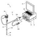
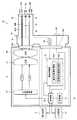
図1は、本発明に係る内視鏡診断装置の構成を表す第1の実施形態の外観図、図2は、その内部構成を表すブロック図である。これらの図に示す内視鏡診断装置10は、所定の波長範囲の光を発生する光源装置12と、光源装置12から発せられる光を導光して被検体の被観察領域に照明光を照射し、被検体からの反射光を撮像する内視鏡装置14と、内視鏡装置14で撮像された画像を画像処理して内視鏡画像を出力するプロセッサ装置16と、プロセッサ装置16から出力される内視鏡画像を表示する表示装置18と、入力操作を受け付ける入力装置20とによって構成されている。 FIG. 1 is an external view of a first embodiment showing a configuration of an endoscope diagnosis apparatus according to the present invention, and FIG. 2 is a block diagram showing an internal configuration thereof. The endoscopic
ここで、内視鏡診断装置10は、通常光(白色光)を被検体に照射し、その反射光を撮像して通常光画像(白色光画像)を表示(観察)する通常光観察モード(白色光観察モード)と、特殊光(狭帯域光)を被検体に照射し、その反射光を撮像して特殊光画像(狭帯域光画像)を表示する特殊光観察モード(狭帯域光観察モード)とを有する。各観察モードは、内視鏡装置14の切り替えスイッチ66や入力装置20から入力される指示に基づき、適宜切り替えられる。 Here, the
光源装置12は、光源制御部22と、それぞれ波長範囲の異なるレーザ光を発する2種のレーザ光源LD1,LD2と、コンバイナ(合波器)24と、カプラ(分波器)26とによって構成されている。 The
本実施形態において、レーザ光源LD1,LD2からは、それぞれ、中心波長が異なる405nm、445nmである、青色の所定の波長範囲(例えば、中心波長±10nm)の狭帯域光が発せられる。レーザ光源LD1は、狭帯域光画像を撮像するための光源であり、レーザ光源LD2は、通常光観察用の励起光を発生して、後述する蛍光体から白色光(疑似白色光)を発生させるための光源である。 In the present embodiment, the laser light sources LD1 and LD2 emit blue light in a predetermined wavelength range (for example, center wavelength ± 10 nm) having different center wavelengths of 405 nm and 445 nm, respectively. The laser light source LD1 is a light source for picking up a narrowband light image, and the laser light source LD2 generates excitation light for normal light observation and generates white light (pseudo white light) from a phosphor described later. For the light source.
なお、白色光を発生するための白色光光源(通常光光源)は、励起光および蛍光体の組合せに限定されず、白色光を発するものであればよく、例えば、キセノンランプ、ハロゲンランプ、白色LED(発光ダイオード)などを利用することもできる。また、レーザ光源LD1,LD2から発せられるレーザ光の波長は上記に限定されず、同様の役割を果たす波長のレーザ光を適宜選択することができる。例えば、レーザ光源LD1から発せられるレーザ光は、血液中のヘモグロビンの吸光係数が高い、青色の395nm〜455nmの波長範囲に含まれる所定の波長範囲の狭帯域光であることが望ましい。また、本実施形態の場合のように、白色光光源として、445nm±10nmの波長範囲のレーザ光を発するレーザ光源LD2と蛍光体を備える場合、狭帯域光画像を撮像するための光源として、レーザ光源LD1から発せられる中心波長405nmのレーザ光の代わりに、中心波長445nmのレーザ光を利用することもできる。これにより、レーザ光源LD1を省き、コストダウンできるという利点がある。 In addition, the white light source (normal light source) for generating white light is not limited to the combination of excitation light and phosphor, and any light source that emits white light may be used. For example, a xenon lamp, a halogen lamp, white light An LED (light emitting diode) or the like can also be used. Further, the wavelength of the laser light emitted from the laser light sources LD1 and LD2 is not limited to the above, and laser light having a wavelength that plays a similar role can be appropriately selected. For example, the laser light emitted from the laser light source LD1 is desirably narrow band light in a predetermined wavelength range included in a blue wavelength range of 395 nm to 455 nm, which has a high absorption coefficient of hemoglobin in blood. Further, as in the case of the present embodiment, when a white light source is provided with a laser light source LD2 that emits laser light in a wavelength range of 445 nm ± 10 nm and a phosphor, a laser as a light source for capturing a narrowband light image Instead of the laser beam having a center wavelength of 405 nm emitted from the light source LD1, a laser beam having a center wavelength of 445 nm can be used. Thereby, there is an advantage that the laser light source LD1 can be omitted and the cost can be reduced.
レーザ光源LD1,LD2は、後述するプロセッサ装置16の制御部によって制御される光源制御部22によりそれぞれ個別にオンオフ制御および光量制御が行われ、各レーザ光源LD1,LD2の発光のタイミングや光量比率は変更自在になっている。 The laser light sources LD1 and LD2 are individually subjected to on / off control and light amount control by the light
レーザ光源LD1,LD2としては、ブロードエリア型のInGaN系レーザダイオードが利用でき、また、InGaNAs系レーザダイオードやGaNAs系レーザダイオード等を用いることもできる。 As the laser light sources LD1 and LD2, a broad area type InGaN laser diode can be used, and an InGaNAs laser diode, a GaNAs laser diode, or the like can also be used.
光源制御部22は、通常光観察モードの場合、レーザ光源LD1を消灯、レーザ光源LD2を点灯する。また、光源制御部22は、狭帯域光観察モードの場合、レーザ光源LD1,LD2の両方を点灯する。 In the normal light observation mode, the
各レーザ光源LD1,LD2から発せられるレーザ光は、集光レンズ(図示略)を介してそれぞれ対応する光ファイバに入力され、コンバイナ24により合波され、カプラ26により2系統の光に分波されてコネクタ部32Aに伝送される。コンバイナ24およびカプラ26は、ハーフミラー、反射ミラー等によって構成される。なお、これに限らず、コンバイナ24およびカプラ26を用いずに、各レーザ光源LD1,LD2からのレーザ光を直接コネクタ部32Aに送出する構成としてもよい。 Laser light emitted from each of the laser light sources LD1 and LD2 is input to the corresponding optical fiber via a condenser lens (not shown), combined by a
続いて、内視鏡装置14は、被検体内に挿入される内視鏡挿入部の先端から2系統(2灯)の照明光を出射する照明光学系と、被観察領域の内視鏡画像を撮像する1系統(1眼)の撮像光学系とを有する、電子内視鏡である。内視鏡装置14は、内視鏡挿入部28と、内視鏡挿入部28の先端の湾曲操作や観察のための操作を行う操作部30と、内視鏡装置14を光源装置12およびプロセッサ装置16に着脱自在に接続するコネクタ部32A,32Bとを備える。 Subsequently, the
内視鏡挿入部28は、可撓性を持つ軟性部34と、湾曲部36と、先端部(以降、内視鏡先端部とも呼称する)38とから構成されている。 The
湾曲部36は、軟性部34と先端部38との間に設けられ、操作部30に配置されたアングルノブ40の回動操作により湾曲自在に構成されている。この湾曲部36は、内視鏡装置14が使用される被検体の部位等に応じて、任意の方向、任意の角度に湾曲でき、内視鏡先端部38を、所望の観察部位に向けることができる。 The bending
内視鏡先端部38の先端面には、被観察領域へ光を照射する2系統の照明窓42A,42Bと、被観察領域からの反射光を撮像する1系統の観察窓44が配置されている。 On the distal end surface of the endoscope
照明窓42Aの奥には、光ファイバ48Aが収納されている。光ファイバ48Aは、光源装置12からコネクタ部32Aを介してスコープ先端部38まで敷設されている。光ファイバ48Aの先端部(照明窓42A側)には蛍光体54Aが配置され、さらに蛍光体54Aの先にレンズ52A等の光学系が取り付けられている。同様に、照明窓42Bの奥には、先端部に蛍光体54Bおよびレンズ52B等の光学系を有する光ファイバ48Bが収納されている。 An
蛍光体54A,54Bは、レーザ光源LD2からの青色レーザ光の一部を吸収して緑色〜黄色に励起発光する複数種の蛍光物質(例えばYAG系蛍光物質、或いはBAM(BaMgAl10O17)等の蛍光物質)を含んで構成される。通常光観察用の励起光が蛍光体54A,54Bに照射されると、蛍光体54A,54Bから発せられる緑色〜黄色の励起発光光(蛍光)と、蛍光体54A,54Bにより吸収されず透過した青色レーザ光とが合わされて、白色光(疑似白色光)が生成される。The
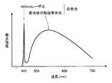
図3は、青色レーザ光源からの青色レーザ光及び青色レーザ光が蛍光体により波長変換された発光スペクトルを示すグラフである。レーザ光源LD2から発せられる青色レーザ光は、中心波長445nmの輝線で表され、青色レーザ光による蛍光体54A,54Bからの励起発光光は、概ね450nm〜700nmの波長範囲で発光強度が増大する分光強度分布となる。この励起発光光と青色レーザ光との合波光によって、上述した疑似白色光が形成される。 FIG. 3 is a graph showing an emission spectrum obtained by converting the wavelength of blue laser light and blue laser light from a blue laser light source with a phosphor. The blue laser light emitted from the laser light source LD2 is represented by a bright line having a center wavelength of 445 nm, and the excitation light emitted from the
ここで、本発明でいう白色光とは、厳密に可視光の全ての波長成分を含むものに限らず、例えば、上述した疑似白色光を始めとして、基準色であるR,G,B等、特定の波長帯の光を含むものであればよい。つまり、本発明のいう白色光には、例えば、緑色から赤色にかけての波長成分を含む光や、青色から緑色にかけての波長成分を含む光等も広義に含まれるものとする。 Here, the white light as referred to in the present invention is not limited to the one that strictly includes all the wavelength components of visible light, and includes, for example, the above-described pseudo white light, R, G, B, which are reference colors, and the like. Any device that includes light in a specific wavelength band may be used. That is, the white light referred to in the present invention broadly includes, for example, light including a wavelength component from green to red, light including a wavelength component from blue to green, and the like.
中心波長405nmのレーザ光を蛍光体54A,54Bに照射した場合に蛍光体54A,54Bから発せられる励起発光光の光強度は、中心波長445nmのレーザ光を蛍光体54A,54Bに照射した場合の数分の一である。つまり、中心波長445nmのレーザ光と一緒に中心波長405nmのレーザ光を蛍光体54A,54Bに照射しても、中心波長405nmのレーザ光によって蛍光体54A,54Bから励起発光光はほとんど発せられない。 When the
このため、本実施形態では、通常光観察用の励起光である中心波長445nmのレーザ光と、血管観察用の狭帯域光である中心波長405nmのレーザ光とを同時に照射する場合に両者を合波し、合波したレーザ光を蛍光体54A,54Bに照射する。なお、例えば、1系統の照明光学系を蛍光体なしとし、蛍光体のない光ファイバにより中心波長405nmのレーザ光を導光して被検体に照射してもよい。 For this reason, in this embodiment, when irradiating laser light with a central wavelength of 445 nm, which is excitation light for normal light observation, and laser light with a central wavelength of 405 nm, which is a narrow band light for blood vessel observation, both are combined. The
照明窓42A側および照明窓42B側の照明光学系は同等の構成および作用のものであって、照明窓42A,42Bからは、基本的に同時に同等の照明光が照射される。なお、照明窓42A,42Bからそれぞれ異なる照明光を照射させることもできる。また、2系統の照明光を出射する照明光学系を有することは必須ではなく、例えば、1系統や4系統の照明光を出射する照明光学系でも同等の機能を実現することができる。 The illumination optical systems on the
観察窓44の奥には、被検体の被観察領域の像光を取り込むための対物レンズユニット56等の光学系が取り付けられ、さらに対物レンズユニット56の奥には、被観察領域の画像情報を取得するCCD(Charge Coupled Device)イメージセンサやCMOS(Complementary Metal-Oxide Semiconductor)イメージセンサ等の撮像素子58(第1撮像素子)が取り付けられている。 An optical system such as an
撮像素子58は、対物レンズユニット56からの光を受光面(撮像面)で受光し、受光した光を光電変換して撮像信号(アナログ信号)を出力する。撮像素子58の受光面には、図4に示す、可視光の約370〜720nmの波長範囲を3分割する分光透過率を有する、R色(約580nm〜760nm)、G色(約450nm〜630nm)、B色(約380nm〜510nm)のカラーフィルタが設けられ、R画素、G画素、B画素の3色の画素を1組として、複数組の画素がマトリクス状に配列されている。 The
光源装置12から光ファイバ48A,48Bによって導光された光は、内視鏡先端部38から被検体の被観察領域に向けて照射される。そして、照明光が照射された被観察領域の様子が対物レンズユニット56により撮像素子58の受光面上に結像され、撮像素子58により光電変換されて撮像される。撮像素子58からは、撮像された被検体の被観察領域の撮像信号(アナログ信号)が出力される。 The light guided from the
撮像素子58から出力される画像(通常光画像、狭帯域光画像)の撮像信号(アナログ信号)は、スコープケーブル62を通じてA/D変換器64に入力される。A/D変換器64は、撮像素子58からの撮像信号(アナログ信号)を画像信号(デジタル信号)に変換する。変換後の画像信号は、コネクタ部32Bを介してプロセッサ装置16の画像処理部に入力される。 An image signal (analog signal) of an image (normal light image, narrow band light image) output from the
なお、図示はしていないが、操作部30及び内視鏡挿入部28の内部には、組織採取用処置具等を挿入する鉗子チャンネルや、送気・送水用のチャンネル等、各種のチャンネルが設けられている。 Although not shown in the drawing, various channels such as a forceps channel for inserting a tissue collection treatment tool, a channel for air supply / water supply, and the like are provided inside the
続いて、プロセッサ装置16は、制御部68と、画像処理部70と、記憶部72とを備えている。制御部68には、表示装置18および入力装置20が接続されている。プロセッサ装置16は、内視鏡装置14の切り替えスイッチ66や入力装置20から入力される指示に基づき、光源装置12の光源制御部22を制御するとともに、内視鏡装置14から入力される画像信号を画像処理し、表示用画像を生成して表示装置18に出力する。 Subsequently, the
制御部68は、内視鏡装置14の切り替えスイッチ66や入力装置20からの指示、例えば、観察モード等の指示に基づいて、画像処理部70および光源装置12の光源制御部22の動作を制御する。 The
画像処理部70は、制御部68の制御の基で、観察モードに基づき、通常光画像、狭帯域光画像の画像種別に応じて、内視鏡装置14から入力される画像信号に対して所定の画像処理を施す。画像処理部70で処理された画像信号は、制御部68に送られて、制御部68で各種情報と共に内視鏡観察画像にされて表示装置18に表示され、必要に応じて、メモリやストレージ装置からなる記憶部72に記憶される。 Under the control of the
画像処理部70は、通常光画像処理部70Aと、狭帯域光画像処理部70Bとを備えている。通常光画像処理部70A、狭帯域光画像処理部70Bは、それぞれ、通常光観察モード、狭帯域光観察モードの場合に、通常光画像、狭帯域光画像の画像信号に対して、それぞれの内視鏡画像に適した所定の画像処理を施し、表示用の通常光画像信号、狭帯域光画像信号を出力(生成)する。 The
狭帯域光画像処理部70Bは、図5に示すように、強調輝度信号算出部74と、ヘモグロビンインデックス算出部76と、変換テーブル78と、強調色差信号算出部80と、画像信号変換部82とを備えている。 As shown in FIG. 5, the narrow-band light
強調輝度信号算出部74は、狭帯域光画像の青色(B画素)の画像信号Bを強調した強調輝度信号を算出する。本実施形態の場合、強調輝度信号算出部74は、青色の画像信号Bと緑色の画像信号Gとを所定の比率で重み付けして強調輝度信号Yを算出する。 The enhanced luminance
ヘモグロビンインデックス算出部76は、狭帯域光画像の緑色(G画素)の画像信号Gおよび赤色(R画素)の画像信号Rから、本実施形態の場合、ln(R/G)で粘膜中の中深層の血液濃度の表すヘモグロビンインデックスrRGを算出する。 In the present embodiment, the hemoglobin
変換テーブル78は、ヘモグロビンインデックスrRGの値が大きくなるに従って、赤色の色差信号Crの値が大きく、かつ、青色の色差信号Cbの値が小さくなるように変換するためのものである。 The conversion table 78 is used for conversion so that the value of the red color difference signal Cr increases and the value of the blue color difference signal Cb decreases as the value of the hemoglobin index rRG increases.
強調色差信号算出部80は、変換テーブル78を用いて、ヘモグロビンインデックスrRgの値に応じて赤味を強調した強調色差信号(色差信号Cr、Cbを含む)を算出する。本実施形態の場合、強調色差信号算出部80は、ヘモグロビンインデックスrRGの値が大きくなるに従って赤味が増すような強調色差信号を算出する。 The enhanced color difference
画像信号変換部82は、強調輝度信号Yおよび強調色差信号(Cr,Cb)から表示用の内視鏡画像の画像信号(表示用の狭帯域光画像信号)、本実施形態の場合、RGBの画像信号を生成する。 The image
表示用の通常光画像信号、狭帯域光画像信号は、例えば、1枚(1フレーム)の画像を単位として記憶部72に記憶される。 The normal light image signal and the narrowband light image signal for display are stored in the
画像処理部70から出力される表示用の通常光画像信号、狭帯域光画像信号は、制御部68に入力される。制御部68は、観察モードに従って、表示用の通常光画像信号、狭帯域光画像信号に基づき、表示用の通常光画像、狭帯域光画像のいずれかを表示装置18に表示する。 The normal light image signal for display and the narrow-band light image signal output from the
次に、内視鏡診断装置10の動作を説明する。 Next, the operation of the
通常光観察モードの場合、光源制御部22の制御により、レーザ光源LD1が消灯され、レーザ光源LD2が点灯される。レーザ光源LD2から発せられる中心波長445nmのレーザ光は蛍光体54A,54Bに照射され、蛍光体54A,54Bから発せられる白色光が被検体に照射され、その反射光が撮像素子58で受光されて通常光画像が撮像される。 In the normal light observation mode, under the control of the light
撮像素子58から出力される通常光画像の撮像信号(アナログ信号)は、A/D変換器62により画像信号(デジタル信号)に変換され、観察モードに従って、画像処理部68の通常光画像処理部70Aにより通常光画像に適した所定の画像処理が施され、表示用の通常光画像信号が出力される。そして、制御部64により、表示用の通常光画像信号に対応する通常光画像が表示装置18上に表示される。 The imaging signal (analog signal) of the normal light image output from the
一方、狭帯域光観察モードの場合、光源制御部22の制御により、レーザ光源LD1,LD2の両方が点灯される。レーザ光源LD1から発せられる中心波長405nmのレーザ光と、レーザ光源LD2から発せられる中心波長445nmのレーザ光によって励起され、蛍光体54A,54Bから発せられる白色光とが、所定の発光比率で被検体に同時に照射され、その反射光が撮像素子58で受光されて狭帯域光画像が撮像される。 On the other hand, in the narrow-band light observation mode, both the laser light sources LD1 and LD2 are turned on under the control of the light
撮像素子58から出力される狭帯域光画像の撮像信号(アナログ信号)は、A/D変換器62により画像信号(デジタル信号)に変換され、観察モードに従って、画像処理部68の狭帯域光画像処理部70Bにより狭帯域光画像に適した所定の画像処理が施され、表示用の狭帯域光画像信号が出力される。そして、制御部64により、表示用の狭帯域光画像信号に対応する狭帯域光画像が表示装置18上に表示される。 The imaging signal (analog signal) of the narrowband optical image output from the
以下、狭帯域光観察モードの場合の画像処理について説明する。 Hereinafter, image processing in the narrow-band light observation mode will be described.
狭帯域光画像処理部70Bは、まず、強調輝度信号算出部74により、狭帯域光画像のB,G,Rの画素の画像信号から、下記式(1)を用いて、B画素の画像信号とG画素の画像信号とを線形結合して強調輝度信号Yを算出する。
Y=b*B+g*G … (1)First, the narrowband light
Y = b * B + g * G (1)
ここで、b,gは、重み付け係数である。強調輝度信号Yにおいて、例えば、B画素の成分とG画素の成分が、7:3となるように重み付けを行う。B画素の成分は表層血管の情報を表すため、B画素の成分を重み付けして増加させることにより、表層血管を強調することができる。また、必須ではないが、強調輝度信号Yの算出にG画素の成分を含めることによって、中深層の血管情報を含めることができる。 Here, b and g are weighting coefficients. In the enhanced luminance signal Y, for example, weighting is performed so that the B pixel component and the G pixel component are 7: 3. Since the component of the B pixel represents information on the superficial blood vessel, the superficial blood vessel can be emphasized by weighting and increasing the component of the B pixel. Although not essential, by including the G pixel component in the calculation of the enhanced luminance signal Y, it is possible to include blood vessel information in the middle and deep layers.
続いて、ヘモグロビンインデックス算出部76により、狭帯域光画像のB,G,Rの画素(B,G,R色)の画像信号から、下記式(2)を用いてヘモグロビンインデックスrRGを算出する。
rRG=ln(R/G) … (2)Subsequently, the hemoglobin
rRG = ln (R / G) (2)
ヘモグロビンインデックスrRGの値は、中深層のヘモグロビン密度(血液濃度)が大きくなるに応じて大きくなるという性質がある。従って、この性質を利用して、以下の手順で、表層血管の強調表示と中深層血液濃度の分布表示を同時に実現する。 The value of the hemoglobin index rRG has a property that it increases as the hemoglobin density (blood concentration) in the mid-deep layer increases. Therefore, by utilizing this property, the superficial blood vessel emphasis display and the mid-deep blood concentration distribution display are realized simultaneously by the following procedure.
続いて、強調色差信号算出部80により、変換テーブル78を用いて、ヘモグロビンインデックスrRBから強調色差信号を算出する。本実施形態の場合、強調色差信号は赤色の色差信号Crおよび青色の色差信号Cbを含む。 Subsequently, the enhanced color difference
図6は、ヘモグロビンインデックスと色差信号との関係を表す一例の変換テーブルである。同図の縦軸は色差信号(ないし後述する補正値)、横軸はヘモグロビンインデックスrRGである。この変換テーブルでは、ヘモグロビンインデックスrRGの値が大きくなるに従って、一次関数的に比例して、赤色の色差信号Crが大きく、かつ、青色の色差信号Cbが小さくなる。 FIG. 6 is an example of a conversion table showing the relationship between the hemoglobin index and the color difference signal. In the figure, the vertical axis represents the color difference signal (or correction value described later), and the horizontal axis represents the hemoglobin index rRG. In this conversion table, as the value of the hemoglobin index rRG increases, the red color difference signal Cr increases and the blue color difference signal Cb decreases in proportion to a linear function.
従って、この変換テーブルを使用することにより、ヘモグロビンインデックスrRGの値、つまり、中深層の血液濃度が大きくなるに従って、表示用の狭帯域光画像における赤味が強調されるように、ヘモグロビンインデックスrRGの値に対応する色差信号Cr,Cbを算出することができる。例えば、ヘモグロビンインデックスrRGの値が1.2の時、色差信号Cr,Cbの値はそれぞれ50、−50となる。 Therefore, by using this conversion table, as the value of the hemoglobin index rRG, that is, the redness in the narrowband light image for display is enhanced as the blood concentration in the middle depth increases, the hemoglobin index rRG Color difference signals Cr and Cb corresponding to the values can be calculated. For example, when the value of the hemoglobin index rRG is 1.2, the values of the color difference signals Cr and Cb are 50 and −50, respectively.
続いて、画像信号変換部82により、上記で算出した強調輝度信号Y、および、強調色差信号、つまり、色差信号Cr,CbをRGBの画像信号に変換して表示用の狭帯域光画像信号を生成する。 Subsequently, the image
これにより、表示用の狭帯域光画像信号に対応する狭帯域光画像では、中深層の血液濃度が画像の赤味の程度で表現され、ヘモグロビンインデックスrRGの値が大きくなる、つまり、中深層の血液濃度が大きくなるに従って赤味が強く表示される。また、輝度信号がB画素の画像信号に重み付けされて作成されているため、表層血管部分のコントラストが高く(低い輝度値で)表現される。 Thereby, in the narrowband optical image corresponding to the narrowband optical image signal for display, the blood concentration in the middle deep layer is expressed by the degree of redness of the image, and the value of the hemoglobin index rRG increases, that is, in the middle deep layer. As the blood concentration increases, the redness is displayed strongly. In addition, since the luminance signal is created by weighting the image signal of the B pixel, the contrast of the surface blood vessel portion is expressed with a high level (with a low luminance value).
未分化型早期胃癌には、高分化型の癌と比べて腫瘍領域の血管密度が低いという特徴がある。従って、上記のように、内視鏡観察時に、粘膜中深層の血液量の分布の情報と、強調された表層血管とを同時に表示させることにより、粘膜表層の観察だけでは病変部の発見や範囲の診断が困難であるという狭帯域光観察の欠点をカバーし、未分化型も含めた腫瘍病変の診断能向上を図ることができる。 Undifferentiated early gastric cancer is characterized by a lower blood vessel density in the tumor area than well-differentiated cancer. Therefore, as described above, during endoscopic observation, information on the blood volume distribution in the middle mucosa and the emphasized surface blood vessels are displayed simultaneously, so that only the observation of the mucosal surface layer can be used to detect the lesion and the extent of the lesion. Therefore, it is possible to improve the diagnostic ability of tumor lesions including undifferentiated types.
なお、上記の実施形態では、中深層の血液濃度を擬似カラー表示しているが、例えば、狭帯域光画像を参照画像として、中深層の血液濃度を表示することもできる。 In the above embodiment, the blood concentration in the mid-deep layer is displayed in pseudo color. However, for example, the blood concentration in the mid-deep layer can be displayed using a narrowband light image as a reference image.
この場合、まず、狭帯域光画像のB,G,Rの画素の画像信号から、下記式(3)を用いて、赤色の色差信号Crおよび青色の色差信号Cbを算出する。
Cr=Y−R、Cb=Y−B … (3)In this case, first, the red color difference signal Cr and the blue color difference signal Cb are calculated from the image signals of the B, G, and R pixels of the narrowband light image using the following equation (3).
Cr = Y-R, Cb = Y-B (3)
続いて、上記で算出した色差信号Cr,Cbに対して、例えば、図6に示すテーブルの色差信号Cr,Cbを補正値として加算する。そして、同様に、輝度信号Yおよび色差信号Cr,CbをRGBの画像信号に変換して表示する。 Subsequently, for example, the color difference signals Cr and Cb in the table shown in FIG. 6 are added as correction values to the color difference signals Cr and Cb calculated above. Similarly, the luminance signal Y and the color difference signals Cr and Cb are converted into RGB image signals and displayed.
これにより、擬似カラー表示の場合と同様の効果を得ることができる。中深層の血液濃度を擬似カラー表示した場合、ヘモグロビンインデックスrRGの値が小さくなるに従って色差信号Cr,Cbの値が小さくなり、次第にモノクロ表示に近づく。これに対し、狭帯域光画像を参照画像として表示することにより、血液濃度が小さい場合であっても狭帯域光画像の色味を基準として赤味を強調した画像を表示することができる。 Thereby, the same effect as in the case of pseudo color display can be obtained. When the blood concentration in the middle and deep layers is displayed in pseudo color, the values of the color difference signals Cr and Cb become smaller as the value of the hemoglobin index rRG becomes smaller, and gradually approaches monochrome display. On the other hand, by displaying the narrow band light image as a reference image, it is possible to display an image in which red is emphasized based on the color of the narrow band light image even when the blood concentration is small.
次に、第2の実施形態について説明する。 Next, a second embodiment will be described.
図7は、図1に示す内視鏡診断装置の内部構成を表す第2の実施形態のブロック図である。同図に示す内視鏡診断装置の光源装置12は、白色光光源84と、狭帯域フィルタ86と、回転制御部88と、レンズ90と、カプラ26とによって構成されている。 FIG. 7 is a block diagram of the second embodiment showing the internal configuration of the endoscope diagnosis apparatus shown in FIG. The
白色光光源84は、例えば、光源装置12の電源がオンのときに常にオンして白色光を発する。白色光光源84は、白色光を発するものであれば何ら制限はなく、例えば、キセノンランプや、蛍光灯、水銀灯などの白色灯が使用される。 For example, the
狭帯域フィルタ86は、白色光光源84から発せられる白色光をフィルタリングして、所定の波長範囲の光を透過させるバンドパスフィルタである。狭帯域フィルタ86は、円板形状で、B色の415nm±10nmの波長範囲の第1狭帯域光、G色の540〜580nmの波長範囲の第2狭帯域光、R色の590〜700nmの波長範囲の狭帯域光を透過させる第1〜第3光透過部とを有する。415nm±10nmの波長範囲の第1狭帯域光は、血液中のヘモグロビンの吸光係数が最も大きい波長範囲である。狭帯域フィルタ86は、白色光光源84とレンズ90との間の光路に対して垂直に配置され、回転制御部88の制御の基で、図示していないモータによって適宜回転される。 The
回転制御部88は、プロセッサ装置16の制御部64の制御の基で、狭帯域フィルタ86の回転を制御する。本実施形態の内視鏡診断装置では、3フレームを1組の撮像期間として面順次方式でB色、G色、R色の内視鏡画像の撮像が行われる。回転制御部88は、1組の撮像期間の第1〜第3フレームにおいて、1フレーム毎に、第1〜第3光透過部が順次光路内に挿入されるように狭帯域フィルタ86の回転を制御する。 The
内視鏡装置14の照明窓42Aの奥には、先端部にレンズ50A等の光学系を有する光ファイバ46Aが収納され、同様に、照明窓42Bの奥には、先端部にレンズ50B等の光学系を有する光ファイバ46Bが収納されている。また、観察窓44の奥には、対物レンズユニット56等の光学系が取り付けられ、その奥に撮像素子59が取り付けられている。本実施形態の撮像素子59は、モノクロCCDイメージセンサである。 An
プロセッサ装置16の構成は、第1の実施形態の場合と同様である。 The configuration of the
次に、第2の実施形態の内視鏡診断装置の動作を説明する。 Next, the operation of the endoscope diagnosis apparatus according to the second embodiment will be described.
本実施形態の内視鏡診断装置では、3フレームを1組の撮像期間として面順次方式でB色、G色、R色の内視鏡画像の撮像が行われる。 In the endoscope diagnostic apparatus according to the present embodiment, B, G, and R color endoscope images are imaged in a frame sequential manner with 3 frames as a set of imaging periods.
光源装置では、回転制御部88の制御により、1組の撮像期間の第1〜第3フレームにおいて、1フレーム毎に、第1〜第3光透過部が順次光路内に挿入されるように狭帯域フィルタ86の回転が制御される。つまり、1フレーム毎に、第1〜第3狭帯域光が狭帯域フィルタ86を順次透過し、レンズ90で集光され、カプラ26により2系統の光に分波されてコネクタ部32Aに伝送される。 In the light source device, the
内視鏡装置14では、光源装置12から発せられる第1〜第3狭帯域光が、光ファイバ46Aおよび46Bによって導光されて被検体の被観察領域に照射され、その反射光が撮像素子65によって撮像される。撮像素子65からは、第1〜第3狭帯域光の反射光に対応する輝度値を有するB色、G色、R色の内視鏡画像の撮像信号が順次出力され、A/D変換器62によってB色、G色、R色の内視鏡画像の画像信号に順次変換される。 In the
これ以後の通常光観察モードおよび狭帯域光観察モードの場合の動作は、いずれも第1の実施形態の場合と同様である。 The subsequent operations in the normal light observation mode and the narrow-band light observation mode are the same as those in the first embodiment.
つまり、通常光観察モードの場合、B色、G色、R色の内視鏡画像の画像信号に対応する通常光画像が表示装置18上に表示される。 That is, in the normal light observation mode, the normal light image corresponding to the image signals of the B, G, and R endoscopic images is displayed on the
一方、狭帯域光観察モードの場合、B色およびG色の内視鏡画像の画像信号から、強調輝度信号Yが算出され、G色およびR色の内視鏡画像の画像信号から、ヘモグロビンインデックスrRGが算出される。そして、変換テーブル78を用いて、ヘモグロビンインデックスrRBから強調色差信号が算出され、強調輝度信号Y、および、強調色差信号がRGBの画像信号に変換されて狭帯域光画像が表示装置18上に表示される。 On the other hand, in the narrow-band light observation mode, the enhanced luminance signal Y is calculated from the image signals of the B and G endoscope images, and the hemoglobin index is calculated from the image signals of the G and R endoscope images. rRG is calculated. Then, using the conversion table 78, an enhanced color difference signal is calculated from the hemoglobin index rRB, the enhanced luminance signal Y and the enhanced color difference signal are converted into RGB image signals, and a narrowband light image is displayed on the
本発明は、基本的に以上のようなものである。
以上、本発明について詳細に説明したが、本発明は上記実施形態に限定されず、本発明の主旨を逸脱しない範囲において、種々の改良や変更をしてもよいのはもちろんである。The present invention is basically as described above.
Although the present invention has been described in detail above, the present invention is not limited to the above-described embodiment, and it is needless to say that various improvements and modifications may be made without departing from the gist of the present invention.
10 内視鏡診断装置
12 光源装置
14 内視鏡装置
16 プロセッサ装置
18 表示装置
20 入力装置
22 光源制御部
24 コンバイナ
26 カプラ
28 内視鏡挿入部
30 操作部
32A,32B コネクタ部
34 軟性部
36 湾曲部
38 先端部
40 アングルノブ
42A,42B 照明窓
44 観察窓
46A,46B,48A,48B 光ファイバ
50A,50B,52A,52B レンズ
54A,54B 蛍光体
56 対物レンズユニット
58,59 撮像素子
62 スコープケーブル
64 A/D変換器
66 切り替えスイッチ
68 制御部
70 画像処理部
70A 通常光画像処理部
70B 狭帯域光画像処理部
72 記憶部
74 強調輝度信号算出部
76 ヘモグロビンインデックス算出部
78 変換テーブル
80 強調色差信号算出部
82 画像信号変換部
84 白色光光源
86 狭帯域フィルタ
88 回転制御部
90 レンズ
LD1,LD2 レーザ光源DESCRIPTION OF
Claims (16)
Translated fromJapanese青色の所定の波長範囲の第1狭帯域光を発する第1狭帯域光光源と、
青色、緑色および赤色のカラーフィルタを受光面に有し、狭帯域光観察モードの場合に、被検体に所定の発光比率で照射される前記白色光および前記第1狭帯域光の該被検体からの反射光を受光して狭帯域光画像を撮像する撮像素子と、
前記狭帯域光画像の青色の画像信号Bを強調した強調輝度信号を算出し、前記狭帯域光画像の緑色の画像信号Gおよび赤色の画像信号Rから粘膜中の中深層の血液濃度を表するヘモグロビンインデックスを算出し、該ヘモグロビンインデックスの値に応じて赤味を強調した強調色差信号を算出し、前記強調輝度信号および強調色差信号から表示用の内視鏡画像の画像信号を生成する画像処理部と、
前記表示用の内視鏡画像の画像信号に対応する内視鏡画像を表示する表示装置とを備えていることを特徴とする内視鏡診断装置。A white light source that emits white light;
A first narrowband light source that emits first narrowband light in a predetermined wavelength range of blue;
From the subject of the white light and the first narrow-band light that have blue, green, and red color filters on the light receiving surface and irradiate the subject at a predetermined emission ratio in the narrow-band light observation mode. An imaging device that receives the reflected light of the image and picks up a narrow-band light image;
An enhanced luminance signal obtained by emphasizing the blue image signal B of the narrowband light image is calculated, and the blood concentration in the middle and deep layers in the mucous membrane is expressed from the green image signal G and the red image signal R of the narrowband light image. Image processing for calculating a hemoglobin index, calculating an enhanced color difference signal in which redness is enhanced according to the value of the hemoglobin index, and generating an image signal of an endoscopic image for display from the enhanced luminance signal and the enhanced color difference signal And
An endoscope diagnosis apparatus comprising: a display device that displays an endoscope image corresponding to an image signal of the display endoscope image.
前記白色光光源は、前記第1狭帯域光光源を前記第2狭帯域光光源として使用するものである請求項8または9に記載の内視鏡診断装置。The first narrowband light and the second narrowband light are light having a wavelength range of 445 nm ± 10 nm,
The endoscope diagnostic apparatus according to claim 8 or 9, wherein the white light source uses the first narrow-band light source as the second narrow-band light source.
前記白色光を、青色の所定の波長範囲の狭帯域光、緑色の光および赤色の光に分離するカラーフィルタと、
狭帯域光観察モードの場合に、被検体に面順次方式で照射される、前記青色の所定の波長範囲の狭帯域光、緑色の光および赤色の光の該被検体からの反射光を受光して青色の狭帯域光画像、緑色の通常光画像および赤色の通常光画像を順次撮像する撮像素子と、
前記青色の狭帯域光画像の画像信号Bを強調した強調輝度信号Yを算出し、前記緑色の通常光画像の画像信号Gおよび前記赤色の通常光画像の画像信号Rから粘膜中の中深層の血液濃度を表するヘモグロビンインデックスを算出し、該ヘモグロビンインデックスの値に応じて赤味を強調した強調色差信号を算出し、前記強調輝度信号および強調色差信号から表示用の内視鏡画像の画像信号を生成する画像処理部と、
前記表示用の内視鏡画像の画像信号に対応する内視鏡画像を表示する表示装置とを備えていることを特徴とする内視鏡診断装置。A white light source that emits white light;
A color filter that separates the white light into blue narrow-band light, green light, and red light in a predetermined wavelength range;
In the narrow-band light observation mode, it receives the reflected light from the subject of the narrow-band light, green light, and red light in the predetermined wavelength range of blue that is irradiated onto the subject in a frame sequential manner. An image sensor that sequentially captures a blue narrow-band light image, a green normal light image, and a red normal light image;
An enhanced luminance signal Y obtained by emphasizing the image signal B of the blue narrow-band light image is calculated. From the image signal G of the green normal light image and the image signal R of the red normal light image, A hemoglobin index representing a blood concentration is calculated, an enhanced color difference signal in which redness is enhanced according to the value of the hemoglobin index is calculated, and an image signal of an endoscopic image for display is calculated from the enhanced luminance signal and the enhanced color difference signal An image processing unit for generating
An endoscope diagnosis apparatus comprising: a display device that displays an endoscope image corresponding to an image signal of the display endoscope image.
Priority Applications (3)
| Application Number | Priority Date | Filing Date | Title |
|---|---|---|---|
| JP2011002950AJP5159904B2 (en) | 2011-01-11 | 2011-01-11 | Endoscopic diagnosis device |
| US13/286,841US20120179050A1 (en) | 2011-01-11 | 2011-11-01 | Endoscope diagnosis system |
| EP11188217.1AEP2474265B1 (en) | 2011-01-11 | 2011-11-08 | Endoscope diagnosis system |
Applications Claiming Priority (1)
| Application Number | Priority Date | Filing Date | Title |
|---|---|---|---|
| JP2011002950AJP5159904B2 (en) | 2011-01-11 | 2011-01-11 | Endoscopic diagnosis device |
Publications (3)
| Publication Number | Publication Date |
|---|---|
| JP2012143337A JP2012143337A (en) | 2012-08-02 |
| JP2012143337A5 JP2012143337A5 (en) | 2012-09-13 |
| JP5159904B2true JP5159904B2 (en) | 2013-03-13 |
Family
ID=45062894
Family Applications (1)
| Application Number | Title | Priority Date | Filing Date |
|---|---|---|---|
| JP2011002950AActiveJP5159904B2 (en) | 2011-01-11 | 2011-01-11 | Endoscopic diagnosis device |
Country Status (3)
| Country | Link |
|---|---|
| US (1) | US20120179050A1 (en) |
| EP (1) | EP2474265B1 (en) |
| JP (1) | JP5159904B2 (en) |
Cited By (1)
| Publication number | Priority date | Publication date | Assignee | Title |
|---|---|---|---|---|
| US10574934B2 (en) | 2016-05-24 | 2020-02-25 | Olympus Corporation | Ultrasound observation device, operation method of image signal processing apparatus, image signal processing method, and computer-readable recording medium |
Families Citing this family (17)
| Publication number | Priority date | Publication date | Assignee | Title |
|---|---|---|---|---|
| JP5554253B2 (en)* | 2011-01-27 | 2014-07-23 | 富士フイルム株式会社 | Electronic endoscope system |
| JP5885652B2 (en)* | 2012-12-27 | 2016-03-15 | 株式会社東芝 | Imaging apparatus, endoscope apparatus, and biological pattern enhancement processing method |
| JP6231284B2 (en)* | 2013-02-21 | 2017-11-15 | クラリオン株式会社 | Imaging device |
| JP6150555B2 (en)* | 2013-02-26 | 2017-06-21 | オリンパス株式会社 | Endoscope apparatus, operation method of endoscope apparatus, and image processing program |
| JP5925169B2 (en) | 2013-09-27 | 2016-05-25 | 富士フイルム株式会社 | Endoscope system, operating method thereof, and light source device for endoscope |
| JP5972312B2 (en)* | 2014-03-24 | 2016-08-17 | 富士フイルム株式会社 | Medical image processing apparatus and operating method thereof |
| CN105813538B (en)* | 2014-03-28 | 2018-04-20 | 奥林巴斯株式会社 | Somatoscopy system |
| JPWO2016151672A1 (en)* | 2015-03-20 | 2018-01-11 | オリンパス株式会社 | Living body observation device |
| WO2016151676A1 (en)* | 2015-03-20 | 2016-09-29 | オリンパス株式会社 | Image processing device, image processing method, and biological observation device |
| JP6894894B2 (en)* | 2016-06-22 | 2021-06-30 | オリンパス株式会社 | Image processing device, operation method of image processing device, and operation program of image processing device |
| WO2018142658A1 (en)* | 2017-02-01 | 2018-08-09 | オリンパス株式会社 | Image processing device, operating method for image processing device, and operating program for image processing device |
| CN108670203A (en)* | 2018-06-01 | 2018-10-19 | 深圳开立生物医疗科技股份有限公司 | A kind of imaging device |
| EP3620098B1 (en)* | 2018-09-07 | 2021-11-03 | Ambu A/S | Enhancing the visibility of blood vessels in colour images |
| RU2701102C1 (en)* | 2018-12-17 | 2019-09-24 | Федеральное государственное бюджетное научное учреждение "Томский национальный исследовательский медицинский центр" Российской академии наук" (Томский НИМЦ) | Method of combined endoscopic diagnosis of x-ray negative early recurrences of central lung cancer |
| JP7158562B2 (en)* | 2019-03-19 | 2022-10-21 | オリンパス株式会社 | Endoscope device, operating method and program for endoscope device |
| CN119235236A (en)* | 2024-10-11 | 2025-01-03 | 浙江大学 | Endoscopic device and method for measuring hemoglobin concentration |
| CN119722488A (en)* | 2024-12-19 | 2025-03-28 | 清华大学 | Endoscopic image fusion system and method, image fusion method and device, and equipment |
Family Cites Families (7)
| Publication number | Priority date | Publication date | Assignee | Title |
|---|---|---|---|---|
| JP3559755B2 (en)* | 2000-07-27 | 2004-09-02 | オリンパス株式会社 | Endoscope device |
| EP2319390B1 (en)* | 2000-07-21 | 2016-04-20 | Olympus Corporation | Endoscope apparatus |
| JP2003334163A (en)* | 2002-03-14 | 2003-11-25 | Olympus Optical Co Ltd | Endoscopic image processor |
| JP4554944B2 (en)* | 2004-01-15 | 2010-09-29 | Hoya株式会社 | Endoscope device |
| JP4009626B2 (en)* | 2004-08-30 | 2007-11-21 | オリンパス株式会社 | Endoscope video signal processor |
| DE602009001103D1 (en)* | 2008-06-04 | 2011-06-01 | Fujifilm Corp | Lighting device for use in endoscopes |
| JP5285967B2 (en)* | 2008-06-11 | 2013-09-11 | 富士フイルム株式会社 | LIGHT SOURCE DEVICE AND ENDOSCOPE DEVICE USING THE SAME |
- 2011
- 2011-01-11JPJP2011002950Apatent/JP5159904B2/enactiveActive
- 2011-11-01USUS13/286,841patent/US20120179050A1/ennot_activeAbandoned
- 2011-11-08EPEP11188217.1Apatent/EP2474265B1/enactiveActive
Cited By (1)
| Publication number | Priority date | Publication date | Assignee | Title |
|---|---|---|---|---|
| US10574934B2 (en) | 2016-05-24 | 2020-02-25 | Olympus Corporation | Ultrasound observation device, operation method of image signal processing apparatus, image signal processing method, and computer-readable recording medium |
Also Published As
| Publication number | Publication date |
|---|---|
| EP2474265A3 (en) | 2012-08-01 |
| US20120179050A1 (en) | 2012-07-12 |
| JP2012143337A (en) | 2012-08-02 |
| EP2474265B1 (en) | 2013-08-21 |
| EP2474265A2 (en) | 2012-07-11 |
Similar Documents
| Publication | Publication Date | Title |
|---|---|---|
| JP5159904B2 (en) | Endoscopic diagnosis device | |
| JP5496075B2 (en) | Endoscopic diagnosis device | |
| JP5371946B2 (en) | Endoscopic diagnosis device | |
| JP5303012B2 (en) | Endoscope system, processor device for endoscope system, and method for operating endoscope system | |
| JP5815426B2 (en) | Endoscope system, processor device for endoscope system, and image processing method | |
| JP5460507B2 (en) | Endoscope apparatus operating method and endoscope apparatus | |
| JP5231511B2 (en) | Endoscopic diagnosis device | |
| US9629527B2 (en) | Endoscope system, processor device of endoscope system, and image processing method | |
| JP5222934B2 (en) | Endoscope system, processor device for endoscope system, and method for operating endoscope system | |
| EP2465432A1 (en) | Endoscope apparatus | |
| JP5485215B2 (en) | Endoscope device | |
| US20140340497A1 (en) | Processor device, endoscope system, and operation method of endoscope system | |
| CN108830825B (en) | Endoscope system and method for operating same | |
| JP2012050641A (en) | Endoscope system | |
| JP5396449B2 (en) | Endoscopic diagnosis device | |
| JP2012217673A (en) | Endoscopic diagnosis system | |
| JP2012239815A (en) | Endoscope system and method for displaying endoscope image | |
| JP2012070839A (en) | Light source device and endoscopic diagnostic system | |
| JP5677555B2 (en) | Endoscope device | |
| JP5558331B2 (en) | Endoscope system, processor device for endoscope system, and method for operating endoscope system | |
| JP2015171442A (en) | Light source device for endoscope, and endoscope system | |
| JP5764472B2 (en) | Endoscopic diagnosis device | |
| JP2015231467A (en) | Light source device for endoscope and endoscope system | |
| JP2015231576A (en) | Endoscope system, processor device for endoscope system, and image processing method | |
| JP5970054B2 (en) | Endoscope system, light source device for endoscope system, and method for operating endoscope system |
Legal Events
| Date | Code | Title | Description |
|---|---|---|---|
| A521 | Request for written amendment filed | Free format text:JAPANESE INTERMEDIATE CODE: A523 Effective date:20120605 | |
| A621 | Written request for application examination | Free format text:JAPANESE INTERMEDIATE CODE: A621 Effective date:20120605 | |
| A977 | Report on retrieval | Free format text:JAPANESE INTERMEDIATE CODE: A971007 Effective date:20121119 | |
| TRDD | Decision of grant or rejection written | ||
| A01 | Written decision to grant a patent or to grant a registration (utility model) | Free format text:JAPANESE INTERMEDIATE CODE: A01 Effective date:20121127 | |
| A61 | First payment of annual fees (during grant procedure) | Free format text:JAPANESE INTERMEDIATE CODE: A61 Effective date:20121211 | |
| R150 | Certificate of patent or registration of utility model | Ref document number:5159904 Country of ref document:JP Free format text:JAPANESE INTERMEDIATE CODE: R150 Free format text:JAPANESE INTERMEDIATE CODE: R150 | |
| FPAY | Renewal fee payment (event date is renewal date of database) | Free format text:PAYMENT UNTIL: 20151221 Year of fee payment:3 | |
| R250 | Receipt of annual fees | Free format text:JAPANESE INTERMEDIATE CODE: R250 | |
| R250 | Receipt of annual fees | Free format text:JAPANESE INTERMEDIATE CODE: R250 | |
| R250 | Receipt of annual fees | Free format text:JAPANESE INTERMEDIATE CODE: R250 | |
| R250 | Receipt of annual fees | Free format text:JAPANESE INTERMEDIATE CODE: R250 | |
| R250 | Receipt of annual fees | Free format text:JAPANESE INTERMEDIATE CODE: R250 | |
| R250 | Receipt of annual fees | Free format text:JAPANESE INTERMEDIATE CODE: R250 | |
| R250 | Receipt of annual fees | Free format text:JAPANESE INTERMEDIATE CODE: R250 | |
| R250 | Receipt of annual fees | Free format text:JAPANESE INTERMEDIATE CODE: R250 | |
| R250 | Receipt of annual fees | Free format text:JAPANESE INTERMEDIATE CODE: R250 | |
| R250 | Receipt of annual fees | Free format text:JAPANESE INTERMEDIATE CODE: R250 |