JP5156775B2 - Plant monitoring / control device and maintenance support method thereof - Google Patents
Plant monitoring / control device and maintenance support method thereofDownload PDFInfo
- Publication number
- JP5156775B2 JP5156775B2JP2010052504AJP2010052504AJP5156775B2JP 5156775 B2JP5156775 B2JP 5156775B2JP 2010052504 AJP2010052504 AJP 2010052504AJP 2010052504 AJP2010052504 AJP 2010052504AJP 5156775 B2JP5156775 B2JP 5156775B2
- Authority
- JP
- Japan
- Prior art keywords
- information
- arithmetic
- temporary setting
- maintenance support
- control
- Prior art date
- Legal status (The legal status is an assumption and is not a legal conclusion. Google has not performed a legal analysis and makes no representation as to the accuracy of the status listed.)
- Expired - Fee Related
Links
Images


Classifications
- G—PHYSICS
- G05—CONTROLLING; REGULATING
- G05B—CONTROL OR REGULATING SYSTEMS IN GENERAL; FUNCTIONAL ELEMENTS OF SUCH SYSTEMS; MONITORING OR TESTING ARRANGEMENTS FOR SUCH SYSTEMS OR ELEMENTS
- G05B13/00—Adaptive control systems, i.e. systems automatically adjusting themselves to have a performance which is optimum according to some preassigned criterion
- G05B13/02—Adaptive control systems, i.e. systems automatically adjusting themselves to have a performance which is optimum according to some preassigned criterion electric
- G05B13/0205—Adaptive control systems, i.e. systems automatically adjusting themselves to have a performance which is optimum according to some preassigned criterion electric not using a model or a simulator of the controlled system
- G—PHYSICS
- G05—CONTROLLING; REGULATING
- G05B—CONTROL OR REGULATING SYSTEMS IN GENERAL; FUNCTIONAL ELEMENTS OF SUCH SYSTEMS; MONITORING OR TESTING ARRANGEMENTS FOR SUCH SYSTEMS OR ELEMENTS
- G05B19/00—Programme-control systems
- G05B19/02—Programme-control systems electric
- G05B19/18—Numerical control [NC], i.e. automatically operating machines, in particular machine tools, e.g. in a manufacturing environment, so as to execute positioning, movement or co-ordinated operations by means of programme data in numerical form
- G05B19/409—Numerical control [NC], i.e. automatically operating machines, in particular machine tools, e.g. in a manufacturing environment, so as to execute positioning, movement or co-ordinated operations by means of programme data in numerical form characterised by using manual data input [MDI] or by using control panel, e.g. controlling functions with the panel; characterised by control panel details or by setting parameters
- G—PHYSICS
- G05—CONTROLLING; REGULATING
- G05B—CONTROL OR REGULATING SYSTEMS IN GENERAL; FUNCTIONAL ELEMENTS OF SUCH SYSTEMS; MONITORING OR TESTING ARRANGEMENTS FOR SUCH SYSTEMS OR ELEMENTS
- G05B2219/00—Program-control systems
- G05B2219/30—Nc systems
- G05B2219/31—From computer integrated manufacturing till monitoring
- G05B2219/31103—Configure parameters of controlled devices
- G—PHYSICS
- G05—CONTROLLING; REGULATING
- G05B—CONTROL OR REGULATING SYSTEMS IN GENERAL; FUNCTIONAL ELEMENTS OF SUCH SYSTEMS; MONITORING OR TESTING ARRANGEMENTS FOR SUCH SYSTEMS OR ELEMENTS
- G05B2219/00—Program-control systems
- G05B2219/30—Nc systems
- G05B2219/31—From computer integrated manufacturing till monitoring
- G05B2219/31104—Remote configuration of parameters of controlled devices
Landscapes
- Engineering & Computer Science (AREA)
- General Physics & Mathematics (AREA)
- Automation & Control Theory (AREA)
- Physics & Mathematics (AREA)
- Health & Medical Sciences (AREA)
- Manufacturing & Machinery (AREA)
- Human Computer Interaction (AREA)
- Artificial Intelligence (AREA)
- Computer Vision & Pattern Recognition (AREA)
- Evolutionary Computation (AREA)
- Medical Informatics (AREA)
- Software Systems (AREA)
- Testing And Monitoring For Control Systems (AREA)
Description
Translated fromJapanese本発明は、プラントの運転状態を監視・制御するプラント監視・制御装置およびその保守支援方法に関する。 The present invention relates to a plant monitoring / control device that monitors and controls the operation state of a plant and a maintenance support method thereof.
一般に、発電プラントなどで用いられるプラント監視・制御装置は、プラントの各機器からその運転状況を示す情報(例えば、ボイラの温度、燃焼ガスの流量、タービンの回転速度など)や、監視・操作センタのオペレータによって入力される指示情報に基づき、所定の目的(例えば、タービンの回転速度を一定に保つなど)を達成するために、各機器を制御する情報(例えば、燃焼ガスの流量の増減量など)を出力する。そのために、プラント監視・制御装置には、プラントの各機器から入力される情報と、オペレータによって入力される指示情報と、を用いてプラントの各機器に出力する制御情報を演算するための制御ロジックが組み込まれている。そして、その制御ロジックには、様々な演算素子が含まれている。 In general, a plant monitoring / control device used in a power plant or the like has information (for example, boiler temperature, combustion gas flow rate, turbine rotation speed, etc.) indicating the operation status from each device of the plant, and a monitoring / operation center. Based on the instruction information input by the operator, information for controlling each device (for example, increase / decrease amount of combustion gas flow rate, etc.) to achieve a predetermined purpose (for example, keeping the turbine rotation speed constant, etc.) ) Is output. Therefore, in the plant monitoring / control device, a control logic for calculating control information output to each device of the plant using information input from each device of the plant and instruction information input by the operator Is incorporated. The control logic includes various arithmetic elements.
その演算素子の中には、比例積分素子や折れ線関数素子など、その素子の動作を定めるために所定のパラメータを定義しなければならないものがある。そのような演算素子は、プラント監視・制御装置の制御ロジックで頻繁に用いられ、しかも、そのパラメータの値が制御ロジックの出力(制御情報)に大きな影響を与える場合も多い。そのため、プラントを実際に稼働させて、そのパラメータを現実によく適合するように合わせ込む作業が行われる。その作業は、パラメータチューニングと呼ばれる。 Some of the arithmetic elements, such as a proportional integration element and a polygonal line function element, must define a predetermined parameter in order to determine the operation of the element. Such an arithmetic element is frequently used in the control logic of the plant monitoring / control apparatus, and the value of the parameter often greatly affects the output (control information) of the control logic. For this reason, the plant is actually operated, and the operation of adjusting the parameters so as to fit the reality well is performed. This work is called parameter tuning.
なお、本明細書では、そのパラメータチューニングに、一時的に使用するパラメータの値を設定することを、「仮設定」と呼ぶ。また、プラントの本稼働などに永続的に使用するパラメータとして設定することを、「本設定」と呼ぶ。従って、「本設定」されるパラメータの値は、パラメータの「仮設定」とプラントの試験稼働とを繰り返して得られる最適値が用いられることになる。 In this specification, setting the value of a parameter to be temporarily used for the parameter tuning is referred to as “temporary setting”. In addition, setting as a parameter that is permanently used for actual operation of the plant is called “main setting”. Therefore, the optimum value obtained by repeating the “temporary setting” of the parameter and the test operation of the plant is used as the parameter value to be “mainly set”.
引用文献1には、プラント監視・制御装置の制御ロジックにおけるパラメータチューニングの例、とくに、そのチューニングを支援するコンピュータ(保守支援装置)における操作画面や処理手順の例が開示されている。 Cited Document 1 discloses an example of parameter tuning in the control logic of the plant monitoring / control device, in particular, an example of an operation screen and a processing procedure in a computer (maintenance support device) that supports the tuning.
しかしながら、引用文献1では、パラメータの仮設定と本設定とをとくに区別することがされていないため、次のような不都合が生じている。 However, in the cited document 1, since the parameter temporary setting and the actual setting are not particularly distinguished, the following inconvenience occurs.
引用文献1に記載の支援ツールの操作画面には、制御ロジックの図面が表示され、その表示画面に表示されたパラメータチューニング対象の演算素子の近傍には、そのときその演算素子に設定されているパラメータが表示される。パラメータチューニングの試験担当者には、その表示されたパラメータが、本設定により設定されたものなのか、仮設定により設定されたものなのか、分からなくなることがあった。 On the operation screen of the support tool described in the cited document 1, a drawing of the control logic is displayed. In the vicinity of the parameter tuning target calculation element displayed on the display screen, the calculation element is set at that time. The parameter is displayed. A person in charge of parameter tuning may not know whether the displayed parameter is set by this setting or set by temporary setting.
この場合、パラメータチューニングの試験担当者が演算素子を選択してその演算素子のパラメータが、本設定により設定されたものか、仮設定により設定されたものかを確認するためには、その演算素子のパラメータ設定画面を表示させて、そのパラメータが本設定により設定されたものであるか、仮設定により設定されたものであるかを判断するという面倒な操作が必要であった。 In this case, the person in charge of parameter tuning selects a computing element, and in order to check whether the parameter of the computing element is set by this setting or set by temporary setting, the computing element The parameter setting screen is displayed, and it is necessary to perform a troublesome operation of determining whether the parameter is set by the main setting or the temporary setting.
また、従来用いられている保守支援装置のコンピュータで仮設定によるパラメータチューニングを行う場合には、仮設定したパラメータは制御装置の記憶装置に記憶され、保守支援装置のコンピュータには仮設定前のパラメータが記憶される。この保守支援装置のコンピュータに記憶された仮設定前のパラメータを用いて、制御装置に記憶された仮設定したパラメータをいつでも元に戻すことができる。しかしながら、その元に戻す機能があるがゆえに、試験担当者による何らかの操作誤りによって、仮設定したパラメータが元に戻された場合には、それまで仮設定したパラメータが失われるようなことがあった。 In addition, when parameter tuning by temporary setting is performed by a computer of a maintenance support device that has been conventionally used, the temporarily set parameter is stored in the storage device of the control device, and the parameter before temporary setting is stored in the computer of the maintenance support device. Is memorized. Using the parameters before temporary setting stored in the computer of the maintenance support device, the temporarily set parameters stored in the control device can be restored at any time. However, because there is a function to restore it, if the temporarily set parameters are restored due to some operation error by the tester, the temporarily set parameters may be lost. .
以上のように、従来のプラント監視・制御装置では、制御ロジックのパラメータチューニングを行う場合、その作業効率を向上させるための配慮が十分になされていなかった。そのため、パラメータチューニングの作業効率を十分に向上させることができなかった。 As described above, in the conventional plant monitoring / control apparatus, when the parameter tuning of the control logic is performed, consideration for improving the work efficiency has not been sufficiently taken. Therefore, the parameter tuning work efficiency cannot be sufficiently improved.
そこで、本発明は、パラメータチューニングの作業効率を向上させることが可能なプラント監視・制御装置およびその保守支援方法を提供することを目的とする。 Therefore, an object of the present invention is to provide a plant monitoring / control device and a maintenance support method thereof that can improve the work efficiency of parameter tuning.
本発明のプラント監視・制御装置は、制御装置と保守支援装置とにより構成され、制御装置の記憶装置には、プラントのアクチュエータへ出力する制御情報を演算するための制御ロジック情報およびその制御ロジック情報に含まれる演算素子の演算素子パラメータ情報が記憶され、制御装置は、その制御ロジック情報に従って演算処理を行い、制御情報をプラントへ出力し、また、保守支援装置は、制御装置の記憶装置に記憶されている演算素子パラメータ情報を仮設定して制御装置のパラメータチューニングを支援する。
そして、その制御装置は、保守支援装置から演算素子パラメータ情報の仮設定を求める仮設定要求情報を受信したときには、(1)保守支援装置から送信される仮設定対象演算素子情報を受信し、記憶措置に記憶しておき、(2)記憶装置に記憶されている前記演算素子パラメータ情報のうち、仮設定対象演算素子情報で指定される演算素子に対応付けられた演算素子パラメータ情報を退避し、(3)保守支援装置から送信される仮設定演算素子パラメータ情報を受信して、その仮設定演算素子パラメータ情報により記憶装置に記憶されている演算素子パラメータ情報を更新する。
また、保守支援装置は、前記制御ロジック情報に基づいて制御ロジック図を生成し、その生成した制御ロジック図を表示装置に表示し、さらに、その表示した制御ロジック図に含まれる演算素子のうち、前記仮設定対象演算素子情報に含まれる演算素子の表示を、他の演算素子の表示と識別可能に表示する。The plant monitoring / control device according to the present invention includes a control device and a maintenance support device, and a storage device of the control device includes control logic information for calculating control information to be output to the actuator of the plant and control logic information thereof. The operation element parameter information of the operation elements included in the control element is stored, the control device performs arithmetic processing according to the control logic information, outputs the control information to the plant, and the maintenance support device stores in the storage device of the control device The operation element parameter information is temporarily set to support parameter tuning of the control device.
When the control device receives temporary setting request information for temporary setting of arithmetic element parameter information from the maintenance support device, the control device receives (1) temporary setting target arithmetic device information transmitted from the maintenance support device, and stores it. (2) out of the calculation element parameter information stored in the storage device, save the calculation element parameter information associated with the calculation element specified by the temporary setting target calculation element information, (3) maintenance support apparatus receives temporary setting operation element parameter information transmitted from,to update the calculation device parameter information stored in the storage device by its temporary setting operation element parameterinformation.
Further, themaintenance support device generates a control logic diagram based on the control logic information, displays the generated control logic diagram on a display device, and among the arithmetic elements included in the displayed control logic diagram, The display of the calculation element included in the temporary setting target calculation element information is displayed so as to be distinguishable from the display of other calculation elements.
本発明のプラント監視・制御装置では、制御装置の記憶装置に仮設定対象演算素子情報が記憶されるので、仮設定対象演算素子を他の演算素子と識別することが可能になる。従って、保守支援装置の表示装置に表示される制御ロジック図上で、仮設定対象演算素子を他の演算素子と識別可能に表示することが可能になる。また、仮設定対象演算素子情報で指定される演算素子に対応付けられた仮設定後の演算素子パラメータ情報を保守支援装置にバックアップしておくことも可能になる。 In the plant monitoring / control device of the present invention, the provisional setting target computing element information is stored in the storage device of the control device, so that the provisional setting target computing element can be identified from other computing elements. Therefore, it is possible to display the provisional setting target computing element so as to be distinguishable from other computing elements on the control logic diagram displayed on the display device of the maintenance support apparatus. In addition, it is possible to back up temporarily set calculation element parameter information associated with the calculation element specified by the temporary setting target calculation element information in the maintenance support device.
本発明によれば、プラント監視・制御装置におけるパラメータチューニングの作業効率が向上する。 According to the present invention, the work efficiency of parameter tuning in the plant monitoring / control device is improved.
以下、本発明の実施形態について、図面を参照して詳細に説明する。 Hereinafter, embodiments of the present invention will be described in detail with reference to the drawings.
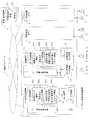
図1は、本発明の実施形態に係るプラント監視・制御装置の構成の例を示した図である。図1に示すように、本発明の実施形態に係るプラント監視・制御装置1は、1つ以上の制御装置2と保守支援装置3とが通信ネットワーク7を介して互いに通信可能に接続されて構成される。制御装置2は、演算処理装置21および記憶装置22を有する一般的なコンピュータまたはPLC(Programmable Logic Controller)などによって構成され、さらに、センサ情報入力装置23および制御情報出力装置24を含んでいる。 FIG. 1 is a diagram illustrating an example of a configuration of a plant monitoring / control device according to an embodiment of the present invention. As shown in FIG. 1, a plant monitoring / control device 1 according to an embodiment of the present invention includes one or
センサ情報入力装置23は、プラント内に設けられた各種のセンサ4(例えば、ボイラの温度計や燃焼ガスの流量計など)に接続され、センサ4からプラントの運転状態を表す情報(例えば、ボイラの温度や燃焼ガスの流量など)を取得する。また、制御情報出力装置24は、プラント内に設けられた各種のアクチュエータ5(例えば、燃焼ガス配管のバルブの開度を調節するモータ)に接続され、アクチュエータ5に対し、その駆動を制御する制御情報(例えば、燃焼ガス配管のバルブの開度情報など)を出力する。 The sensor
制御装置2は、さらに、通信ネットワーク7を介して、プラントの中央管理室などに設置された監視・操作装置6に接続されている。監視・操作装置6は、監視用表示装置61および操作卓62を含んで構成される。監視用表示装置61は、壁などに埋め込まれた大画面の表示装置や卓上型の表示装置などにより構成され、また、操作卓62は、専用のスイッチボードや一般的なキーボードなどによって構成される。監視オペレータは、操作卓62を介して制御装置2に対する様々な指示情報を入力することができ、その入力された指示情報は、通信ネットワーク7を介して制御装置2へ送信される。 The
制御装置2内の記憶装置22には、制御ロジック情報221および演算素子パラメータ情報222が記憶されている。制御ロジック情報221は、センサ情報入力装置23から入力されるセンサ情報や監視・操作装置6から送信された指示情報などに基づき、アクチュエータ5へ出力すべき制御情報を演算する制御ロジックを、制御ロジック図として表すための情報である。なお、演算処理装置21は、制御ロジック情報221を実行可能なプログラムに変換した上で、そのプログラムを実行することにより制御情報を演算し、制御情報出力装置24へ出力する。
制御ロジック情報221が表す制御ロジック図には、様々な演算素子が含まれている。その演算素子の中には、比例積分素子や折れ線関数素子など、その動作特性を定めるパラメータの値を定める必要があるものがある。演算素子パラメータ情報222は、そのような演算素子それぞれについてそのパラメータの値を定めた情報である。なお、そのパラメータの値は、通常、制御ロジック情報221が表す制御ロジック図が設計されるとき、設計者の経験やシミュレーションなどに基づいて定められるが、必要に応じて、パラメータチューニングが行われる。 The control logic diagram represented by the
記憶装置22には、そのパラメータチューニングの際に必要となる仮設定対象演算素子情報223および退避演算素子パラメータ情報224が記憶されるが、その詳細については後記する。 The storage device 22 stores temporary setting target
保守支援装置3は、制御装置2の制御ロジック情報221や演算素子パラメータ情報222の設計、あるいは、制御装置2のパラメータチューニングなどに際して用いられ、演算処理装置31、記憶装置32、表示装置33、入力装置34などを有する一般的なコンピュータによって構成される。なお、表示装置33は、一般的な卓上型の液晶表示装置などであり、入力装置34は、一般的なキーボード、マウスなどである。 The
保守支援装置3は、記憶装置32に記憶されている制御ロジック情報321および演算素子パラメータ情報322を、それぞれ制御装置2の記憶装置22に記憶されている制御ロジック情報221および演算素子パラメータ情報222へローディングすることができる。なお、プラント監視・制御装置1に複数の制御装置2が含まれている場合には、記憶装置32には、それぞれの制御装置2ごとに、それぞれの制御装置2に対応付けられた制御ロジック情報321および演算素子パラメータ情報322が記憶される。ただし、本明細書では、繁雑になるのを避けるために、制御装置2を識別することについての説明を省略する。 The
仮設定対象演算素子情報323は、パラメータチューニングに際して、試験担当者が制御ロジック情報321に含まれる演算素子の中から選択した仮設定対象演算素子を識別する情報である。また、仮設定演算素子パラメータ情報325は、その選択した仮設定対象演算素子に対して、試験担当者が入力した仮設定するパラメータの値を記憶した情報である。これら仮設定対象演算素子の選択および仮設定演算素子パラメータの値の入力は、表示装置33および入力装置34を介して行われる。 The temporary setting target
記憶装置32には、パラメータチューニングの際に入力情報の記憶領域として用いられる仮設定対象演算素子情報323および仮設定演算素子パラメータ情報225が記憶されるが、その詳細については後記する。 The storage device 32 stores temporary setting target
図2は、保守支援装置3の表示装置33に表示される表示画面の例を示した図であり、(a)は、演算素子パラメータ設定前の制御ロジック図表示画面の例、(b)は、演算素子パラメータ設定画面の例、(c)は、演算素子パラメータ設定後の制御ロジック図表示画面の例である。試験担当者がパラメータチューニングを行うときには、保守支援装置3は、入力装置34から入力される所定の指示情報に従って、まず、図2(a)に示すような制御ロジック図を表示装置33に表示する。 FIG. 2 is a diagram showing an example of a display screen displayed on the
図2(a)において、2重丸は、外部に対する入力端子または出力端子、四角は、演算素子、矢印は、情報または信号の移動方向を表している。ちなみに、図2(a)の例では、加算演算素子(+)、関数演算素子(Fx)、信号発生素子(SG)が含まれ、関数演算素子(Fx)および信号発生素子(SG)には、その動作特性を定めるパラメータの値を規定する必要がある。 In FIG. 2A, a double circle indicates an input terminal or an output terminal with respect to the outside, a square indicates an arithmetic element, and an arrow indicates a moving direction of information or a signal. Incidentally, in the example of FIG. 2A, an addition operation element (+), a function operation element (Fx), and a signal generation element (SG) are included, and the function operation element (Fx) and the signal generation element (SG) include It is necessary to specify the value of the parameter that determines the operating characteristics.
なお、実際の制御ロジック図は、図2(a)のように簡単なものではなく、はるかに複雑なものであり、通常、複数画面に亘って表示される。その場合、1画面の制御ロジック図は、従来の紙の図面の1枚に対応させることが多い。例えば、図2(a)に示した制御ロジック図の例では、右下部分の長方形の枠内に、図面のシート番号(SN−003)が表示されている。 Note that the actual control logic diagram is not as simple as that shown in FIG. 2A and is much more complicated, and is usually displayed over a plurality of screens. In that case, the control logic diagram of one screen often corresponds to one of the conventional paper drawings. For example, in the example of the control logic diagram shown in FIG. 2A, the sheet number (SN-003) of the drawing is displayed in the rectangular frame in the lower right part.
試験担当者は、表示装置33に表示された制御ロジック図(図2(a))を介して仮設定対象演算素子を選択することができる。その場合には、試験担当者は、例えば、マウスカーソルなどを用いて、関数演算素子(Fx)を選択する。そうすると、保守支援装置3は、図2(b)に示すような演算素子パラメータ設定画面を表示する。 The person in charge of the test can select the temporary setting target arithmetic element via the control logic diagram (FIG. 2A) displayed on the
図2(b)において、「演算素子名称」は、仮設定対象演算素子として選択された演算素子の種別を表す情報であり、「演算素子識別番号」は、その演算素子を当該制御ロジック図の中でユニークに識別する識別情報である。また、「X1,Y1,X2,Y2,・・・,X10,Y10」は、当該演算素子の動作特性を定めるパラメータの名称である。 In FIG. 2B, the “arithmetic element name” is information indicating the type of the arithmetic element selected as the temporary setting target arithmetic element, and the “arithmetic element identification number” indicates the arithmetic element in the control logic diagram. This is identification information that uniquely identifies them. “X1, Y1, X2, Y2,..., X10, Y10” are the names of parameters that determine the operating characteristics of the arithmetic element.
ここで、前記の各パラメータの名称に対する「現在値」の欄には、当該演算素子に対して、そのとき制御装置2の演算素子パラメータ情報222に記憶されているパラメータの値が表示される。また、「入力値」の欄には、当該パラメータを設定するために試験担当者が入力したパラメータの値が表示される。また、「仮設定値」の欄には、「入力値」の欄に入力されたパラメータの値が、制御装置2の演算素子パラメータ情報222の当該パラメータの値として仮設定されたとき、その仮設定されたパラメータの値として表示される。 Here, in the “current value” column for the name of each parameter, the value of the parameter stored in the calculation
図2(b)の演算素子パラメータ設定画面には、その右下部に「グラフ」、「本設定」、「仮設定」、「終了」などのメニューボタンが表示されている。「仮設定」ボタンは、演算素子パラメータの仮設定処理の実行を指示するボタンであり、例えば、試験担当者が「入力値」の欄に各パラメータの値を入力した後、「仮設定」ボタンをクリックすると、後記にて詳しく説明する演算素子パラメータの仮設定処理が保守支援装置3および制御装置2においてそれぞれ実行される。 In the arithmetic element parameter setting screen of FIG. 2B, menu buttons such as “graph”, “main setting”, “temporary setting”, and “end” are displayed at the lower right. The “temporary setting” button is a button for instructing execution of the calculation element parameter temporary setting process. For example, after the person in charge of the test inputs the value of each parameter in the “input value” field, the “temporary setting” button When is clicked, a temporary setting process of arithmetic element parameters, which will be described in detail later, is executed in the
次に、その演算素子パラメータの仮設定処理の実行が終了すると、保守支援装置3は、図2(b)の演算素子パラメータ設定画面の「入力値」欄表示されていたパラメータの値を「仮設定値」の欄にも表示する。 Next, when the execution of the temporary setting process for the arithmetic element parameter is completed, the
さらに、保守支援装置3は、演算素子パラメータの仮設定した後に制御ロジック図を表示する場合には、図2(c)に示すように、その制御ロジック図において、仮設定対象演算素子(この例では、関数演算素子(Fx))を、例えば、色違いに表示したり、網掛け表示したり、「仮設定」の文字を表示したりすることによって、他の演算素子(仮設定非対象演算素子)と識別可能なように表示する。また、信号発生素子(SG)のように、演算素子付近にパラメータ値(K=2.5)が表示される場合は、パラメータ値を色違いに表示したり、「仮設定」の文字を表示したりすることによって、他の演算素子と識別可能なようにする。 Furthermore, when the
また、図2(b)の演算素子パラメータ設定画面で、「本設定」ボタンがクリックされた場合には、保守支援装置3および制御装置2においては、後記にて説明する演算素子パラメータの本設定処理が実行される。また、「グラフ」ボタンがクリックされた場合には、保守支援装置は、そのとき仮設定されている演算素子パラメータで制御装置2およびプラントが実際に稼働したときに制御装置2において得られる、当該演算素子の出力信号やあらかじめ登録された主要信号の時間推移のグラフが表示装置33に表示される。 Further, when the “main setting” button is clicked on the arithmetic element parameter setting screen of FIG. 2B, the
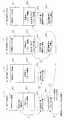
図3は、制御装置2の記憶装置22に記憶される制御ロジック情報221および演算素子パラメータ情報222の構成の例、ならびに、保守支援装置3で設定されてその記憶装置32に記憶される仮設定対象演算素子情報323および仮設定演算素子パラメータ情報325の構成の例を示した図である。 FIG. 3 shows an example of the configuration of the
図3(a)に示すように、制御ロジック情報221は、演算素子名称、演算素子識別番号、シート番号、入力信号名、出力信号名などの情報を含んで構成され、当該演算素子が演算素子パラメータを含むものであれば、そのパラメータのパラメータ名称、パラメータ格納アドレスを、さらに含んで構成される。 As shown in FIG. 3A, the
ここで、演算素子名称は、その演算素子の種別を表す情報であり、演算素子識別番号は、当該演算素子を制御ロジック情報221でユニークに識別するための識別情報である。また、シート番号は、制御ロジック情報221が表す制御ロジック図が複数の図面に分割して表示される場合、その図面のページを識別する番号である。 Here, the arithmetic element name is information representing the type of the arithmetic element, and the arithmetic element identification number is identification information for uniquely identifying the arithmetic element by the
また、入力信号名は、当該演算素子へ入力される信号の信号名称であり、他の演算素子の出力信号名または入力端子の信号名で表される。また、出力信号名は、当該演算素子から出力される信号の信号名称であり、他の演算素子の入力信号名または出力端子の信号名として用いられる。なお、1つの演算素子において、複数の入力信号名が設定されてもよく、また、複数の出力信号名が設定されてもよい。 The input signal name is a signal name of a signal input to the arithmetic element, and is represented by an output signal name of another arithmetic element or a signal name of an input terminal. The output signal name is a signal name of a signal output from the arithmetic element, and is used as an input signal name of another arithmetic element or a signal name of an output terminal. Note that a plurality of input signal names may be set in one arithmetic element, or a plurality of output signal names may be set.
また、パラメータ格納アドレスは、当該演算素子パラメータが演算素子パラメータ情報222の一部として記憶装置22に格納されたときの、記憶装置22におけるアドレスを表す情報である。なお、1つの演算素子に対して複数の演算素子パラメータが1セットにして記憶される場合には、パラメータ格納アドレスは、その1セットのパラメータの先頭アドレスのみを記憶するものとしてもよい。 The parameter storage address is information representing an address in the storage device 22 when the calculation element parameter is stored in the storage device 22 as a part of the calculation
次に、図3(b)に示すように、演算素子パラメータ情報222は、各演算素子のパラメータのパラメータ値のみから構成される。 Next, as shown in FIG. 3B, the calculation
なお、保守支援装置3の記憶装置32に記憶される制御ロジック情報321および演算素子パラメータ情報322は、制御装置2の記憶装置22に記憶される制御ロジック情報221および演算素子パラメータ情報222と同等の構成であるので、その構成は、図3(a)、(b)に示した通りである。 The
次に、図3(c)に示すように、保守支援装置3の記憶装置32に記憶される仮設定対象演算素子情報323は、仮設定対象演算素子として選択された演算素子についての演算素子名称、演算素子識別番号およびシート番号を含んで構成される。すなわち、保守支援装置3は、図2(a)の制御ロジック表示画面を介して仮設定対象演算素子が選択されると、制御ロジック情報321を参照して、その選択された仮設定対象演算素子についての演算素子名称、演算素子識別番号、シート番号などを取り出し、仮設定対象演算素子情報323として記憶装置32に記憶する。 Next, as illustrated in FIG. 3C, the temporary setting target
次に、図3(d)に示すように、保守支援装置3の記憶装置32に記憶される仮設定演算素子パラメータ情報325は、図2(b)の演算素子パラメータ設定画面を介して入力される1つ以上の演算素子パラメータの値により構成される。 Next, as shown in FIG. 3D, the temporary setting calculation
図4は、演算素子パラメータを仮設定する場合の情報の流れの様子を示した図であり、(a)は、試験担当者が仮設定対象演算素子パラメータの入力を終えた時点で保守支援装置3の記憶装置32に記憶されている情報の状況を表し、(d)は、演算素子パラメータの仮設定が終了した時点における制御装置2の記憶装置22に記憶されている情報の状況を表し、(b)、(c)は、(d)に到る途中経過を表している。 FIG. 4 is a diagram illustrating a flow of information when temporarily setting the calculation element parameters. FIG. 4A illustrates a maintenance support device when the tester finishes inputting the temporary setting target calculation element parameters. 3 represents the status of the information stored in the storage device 32, and (d) represents the status of the information stored in the storage device 22 of the
まず、試験担当者が演算素子パラメータを仮設定する場合には、保守支援装置3は、まず、表示装置33に図2(a)に示したような制御ロジック図を表示する。そして、試験担当者が、その表示された制御ロジック図の中から仮設定対象演算素子を選択すると、保守支援装置3は、制御ロジック情報321の中から、その選択された仮設定対象演算素子についての情報を抽出し、仮設定対象演算素子情報323を生成する(図4丸囲み1)。次に、保守支援装置3は、演算素子パラメータ設定画面(図2(b)参照)を介して入力される演算素子パラメータの値に基づき仮設定演算素子パラメータ情報325を生成する(図4丸囲み2)。 First, when the person in charge of the test temporarily sets the arithmetic element parameters, the
次に、仮設定対象演算素子情報323は、制御装置2へ送信され、仮設定対象演算素子情報223として記憶装置22に記憶される(図4丸囲み3)。 Next, the temporary setting target
次に、制御装置2は、仮設定対象演算素子情報223の演算素子識別番号をキーにして制御ロジック情報221を検索して、演算素子識別番号が一致する演算素子のパラメータ格納アドレスを取得し、そのパラメータ格納アドレスが指し示すアドレスに格納されている演算素子パラメータ情報222のパラメータの値を取り出し、退避演算素子パラメータ情報224として、記憶装置22に記憶する(図4丸囲み4)。 Next, the
次に、保守支援装置3が仮設定演算素子パラメータ情報325にそのパラメータ格納アドレスを添付した情報を制御装置2へ送信するので、制御装置2は、仮設定演算素子パラメータ情報325およびそのパラメータ格納アドレスを受信し、そのパラメータ格納アドレスが指し示すアドレスの演算素子パラメータ情報の値を、受信した仮設定演算素子パラメータ325で更新する(図4丸囲み5)。 Next, since the
以上により、保守支援装置3で選択され入力された演算素子の演算素子パラメータが制御装置2の演算素子パラメータ情報222に仮設定されたことになるので、パラメータチューニングの試験担当者は、その仮設定した演算素子パラメータにより制御装置2およびプラントを稼働させ、パラメータチューニングを行うことができる。なお、以上の演算素子パラメータが仮設定の場合には、保守支援装置3の記憶装置32に記憶されている演算素子パラメータ情報322には、何ら変更は加えられない。 As described above, the arithmetic element parameter of the arithmetic element selected and input by the
従って、パラメータチューニングが行われるときに、保守支援装置3の記憶装置32には、それまでのプラントの通常運転時に制御装置2で使用されていた演算素子パラメータ情報322(つまり、以前に「本設定」された演算素子パラメータ情報)、および、そのとき「仮設定」された仮設定演算素子パラメータ情報325の両情報が同時に記憶されていることになる。また、制御装置2は、それまでのプラントの通常運転時に制御装置2で使用していた演算素子パラメータ情報322(つまり、以前に「本設定」された演算素子パラメータ情報)のうち、「仮設定」の対象となった演算素子パラメータ情報の仮設定前のパラメータの値を、退避演算素子パラメータ情報224として記憶装置22に記憶している。 Therefore, when parameter tuning is performed, the storage device 32 of the
従って、制御装置2は、その退避演算素子パラメータ情報224を用いて、演算素子パラメータ情報222をいつでも以前の「本設定」された演算素子パラメータ情報の状態へ戻すことができる。また、保守支援装置3における操作誤りなどにより、制御装置2の記憶装置22に記憶されている「仮設定」された演算素子パラメータを含む演算素子パラメータ情報222が誤って以前の「本設定」された演算素子パラメータ情報に戻された場合にも、保守支援装置3が「仮設定」後の仮設定対象演算素子情報323および仮設定演算素子パラメータ情報325を記憶装置32に記憶しているので、「仮設定」後の制御装置2における演算素子パラメータ情報222を復元することができる。 Therefore, the
図5は、演算素子パラメータの仮設定処理の処理フローの例を示した図である。なお、図5は、図4の情報の流れを処理の流れで表したものであるので、その説明の一部は、図4の説明と重複する。 FIG. 5 is a diagram illustrating an example of a processing flow of the temporary setting process of the arithmetic element parameters. 5 represents the information flow of FIG. 4 as a processing flow, and therefore a part of the description overlaps with the description of FIG.
図5に示すように、保守支援装置3の演算処理装置31は(処理の実行主体は、演算処理装置31であるが、以下、単に、「保守支援装置3は」という)、まず、あらかじめ指定された制御装置2についての制御ロジック情報321に基づき、図2(a)のような制御ロジック図を表示装置33に表示する(ステップS11)。そして、保守支援装置3は、その表示された制御ロジック図の中からマウスカーソルなどで演算素子を選択する情報として、仮設定対象演算素子選択情報を入力するとともに(ステップS12)、仮設定対象演算素子情報323を生成する。 As shown in FIG. 5, the
次に、保守支援装置3は、前記の仮設定対象演算素子選択情報で指定される演算素子について、図2(b)に示すような演算素子パラメータ設定画面を表示する(ステップS13)。そして、保守支援装置3は、その演算素子パラメータ設定画面および入力装置34を介して設定される仮設定対象演算素子の演算素子パラメータの値を入力し(ステップS14)、仮設定演算素子パラメータ情報325を生成する。 Next, the
次に、保守支援装置3は、制御装置2へ演算素子パラメータの仮設定を求める仮設定要求情報を送信し(ステップS15)、さらに、仮設定対象演算素子情報323を送信する(ステップS16)。一方、制御装置2の演算処理装置21は(処理の実行主体は、演算処理装置21であるが、以下、単に、「制御装置2は」という)、保守支援装置3から送信される仮設定要求情報を受信し(ステップS21)、さらに、仮設定対象演算素子情報323を受信する(ステップS22)、受信した仮設定対象演算素子情報323を仮設定対象演算素子情報223として記憶装置22に記憶する。 Next, the
次に、制御装置2は、演算素子パラメータ情報222から、仮設定対象演算素子情報223で指定される仮設定対象演算素子に対応する演算素子パラメータ情報を抽出し、抽出した演算素子パラメータ情報を退避演算素子パラメータ情報として記憶装置22に記憶する(ステップS23)。なお、仮設定対象演算素子情報223で指定される仮設定対象演算素子に対応する演算素子パラメータ情報は、仮設定対象演算素子情報223の演算素子識別番号をキーにして制御ロジック情報221を検索して、演算素子識別番号が一致する演算素子のパラメータ格納アドレスを取得し、そのパラメータ格納アドレスが指し示すアドレスに格納されている演算素子パラメータ情報222のパラメータの値として得ることができる。 Next, the
次に、保守支援装置3が仮設定演算素子パラメータ情報235およびそのパラメータ格納アドレスを送信するので(ステップS17)、制御装置2は、保守支援装置3から送信された仮設定演算素子パラメータ情報235およびそのパラメータ格納アドレスを受信する(ステップS24)。そして、制御装置2は、演算素子パラメータ情報222のうち、パラメータ格納アドレスが指し示すアドレスの演算素子パラメータの値を、仮設定演算素子パラメータ情報325で更新する(ステップS25)。 Next, since the
一方、保守支援装置3は、制御装置2での演算素子パラメータの仮設定が終了すると、その後、制御ロジック図を表示するときには(ステップS18)、図2(c)に示すように、仮設定対象演算素子を、色違い表示するなどして、仮設定非対象演算素子と識別可能なように表示する。 On the other hand, after the temporary setting of the arithmetic element parameters in the
図6は、演算素子パラメータの本設定処理の処理フローの例を示した図である。図6に示すように、ステップS31−S34の処理は、図5のステップS11−S14の処理とほとんど同じである。すなわち、演算素子パラメータの本設定時に試験担当者が行う操作は、仮設定の場合とほとんど同じである。ここでは、ステップS34までの処理の説明を省略する。 FIG. 6 is a diagram showing an example of the processing flow of the processing element parameter setting process. As shown in FIG. 6, the processes in steps S31 to S34 are almost the same as the processes in steps S11 to S14 in FIG. That is, the operation performed by the person in charge of the test at the actual setting of the arithmetic element parameters is almost the same as that of the temporary setting. Here, the description of the processing up to step S34 is omitted.
ステップS34までの処理により、本設定対象演算素子が選択され、その本設定対象演算素子に対する演算素子パラメータの値(本設定演算素子パラメータ情報)が設定されたことになる。そこで、保守支援装置3は、制御装置2へ演算素子パラメータの本設定を求める本設定要求情報を送信し(ステップS35)、さらに、本設定演算素子パラメータ情報およびそのパラメータ格納アドレスを送信する(ステップS36)。一方、制御装置2は、保守支援装置3から送信される本設定要求情報を受信し(ステップS41)、さらに、本設定演算素子パラメータ情報およびそのパラメータ格納アドレスを受信する(ステップS42)。 Through the processing up to step S34, the main setting target arithmetic element is selected, and the value of the arithmetic element parameter (the main setting arithmetic element parameter information) for the main setting target arithmetic element is set. Therefore, the
次に、保守支援装置3は、演算素子パラメータ情報322のうち、パラメータ格納アドレスが指し示すアドレスの演算素子パラメータの値を、前記送信した本設定演算素子パラメータ情報で更新する(ステップS37)。また、制御装置2は、演算素子パラメータ情報222のうち、パラメータ格納アドレスが指し示すアドレスの演算素子パラメータの値を、前記受信した本設定演算素子パラメータ情報で更新する(ステップS43)。 Next, the
すなわち、制御装置2においても、また、保守支援装置3においても、それぞれの記憶装置22,32に記憶されている演算素子パラメータ情報222,322は、保守支援装置3を介して設定された本設定演算素子パラメータ情報で全く同じように更新される。従って、保守支援装置3は、演算素子パラメータ情報の本設定された後も、制御装置2の演算素子パラメータ情報222と同じ演算素子パラメータ情報322を有することに変わりはない。 That is, in the
なお、演算素子のパラメータチューニングでは、仮設定した演算素子パラメータをそのまま本設定の演算素子パラメータとする場合が多いが、その場合には、保守支援装置3は、その記憶装置32に記憶されている演算素子パラメータ情報322を、制御装置2の記憶装置22に記憶されている仮設定演算素子パラメータを含んだ演算素子パラメータ情報222で置き換え、さらに、記憶装置32に記憶されている仮設定対象演算素子情報323および仮設定演算素子パラメータ情報325を消去する。また、制御装置2は、その記憶装置22に記憶されている仮設定対象演算素子情報223および退避演算素子パラメータ情報224を消去する。 In the parameter tuning of arithmetic elements, the temporarily set arithmetic element parameters are often used as the main arithmetic element parameters as they are. In this case, the
以上、本実施形態によれば、演算素子パラメータの仮設定が行われたときには、制御装置2および保守支援装置3は、その記憶装置22,32に、仮設定対象演算素子情報223,323を記憶している。従って、保守支援装置3は、表示装置33に表示する制御ロジック図において、仮設定された演算素子を本設定された演算素子と識別可能なように表示することができる。その結果、パラメータチューニングの試験担当者は、容易に仮設定された演算素子と本設定された演算素子とを区別することができるようになる。 As described above, according to the present embodiment, when the arithmetic element parameter is temporarily set, the
また、保守支援装置3は、以前に本設定された演算素子パラメータ情報322とそのとき仮設定された仮設定演算素子パラメータ情報325とを併せ持っているので、制御装置2の記憶装置22に記憶された仮設定後の演算素子パラメータ情報222が何らかの原因で失われた場合でも、演算素子パラメータ情報322と仮設定演算素子パラメータ情報325を用いて、仮設定後の演算素子パラメータ情報222を復元することができる。 Further, since the
以上のように、本実施形態のプラント監視・制御装置1では、パラメータチューニングの試験担当者にとって使い勝手のよい機能が付加されているので、パラメータチューニングの作業効率が向上する。 As described above, in the plant monitoring / control apparatus 1 according to the present embodiment, functions that are easy to use for the person in charge of parameter tuning are added, so that the work efficiency of parameter tuning is improved.
1 プラント監視・制御装置
2 制御装置
3 保守支援装置
4 センサ
5 アクチュエータ
6 監視・操作装置
7 通信ネットワーク
21 演算処理装置
22 記憶装置
23 センサ情報入力装置
24 制御情報出力装置
31 演算処理装置
32 記憶装置
33 表示装置
34 入力装置
61 監視用表示装置
62 操作卓
221 制御ロジック情報
222 演算素子パラメータ情報
223 仮設定対象演算素子情報
224 退避演算素子パラメータ情報
235 仮設定演算素子パラメータ情報
321 制御ロジック情報
322 演算素子パラメータ情報
323 仮設定対象演算素子情報
325 仮設定演算素子パラメータ情報DESCRIPTION OF SYMBOLS 1 Plant monitoring /
Claims (7)
Translated fromJapanese前記センサから入力されるセンサ情報と前記監視・操作装置から入力される操作情報とを用いた制御ロジックの内容を表した制御ロジック情報、および、前記制御ロジック情報に含まれている演算素子の特性を規定する演算素子パラメータ情報を記憶する記憶装置と、前記制御ロジック情報に従って演算処理を実行し、その演算処理結果を制御情報として前記アクチュエータに出力する演算処理装置と、を含んでなる制御装置と、
前記制御装置に接続され、オペレータが入力する情報に基づいて、前記制御装置の記憶装置に記憶されている前記演算素子パラメータ情報の一部の情報を仮設定してパラメータチューニングを支援する保守支援装置と、
を含んで構成されたプラント監視・制御装置であって、
前記制御装置の演算処理装置は、
前記演算素子パラメータ情報の仮設定の処理を行う構成として、
前記保守支援装置から送信される、前記仮設定の対象演算素子を指定する仮設定対象演算素子情報を受信し、前記記憶装置に記憶する第1の処理部と、
前記記憶装置に記憶されている前記演算素子パラメータ情報のうち、前記受信した仮設定対象演算素子情報で指定される演算素子に対応付けられた演算素子パラメータ情報を、前記記憶装置の、前記演算素子パラメータ情報が記憶されている領域と異なる領域に退避させる第2の処理部と、
前記保守支援装置から送信される、前記仮設定対象演算素子情報で指定される演算素子に対応する仮設定演算素子パラメータ情報を受信して、前記記憶装置に記憶されている前記演算素子パラメータ情報のうち、前記仮設定対象演算素子情報で指定される演算素子に対応付けられた演算素子パラメータ情報を、前記受信した仮設定演算素子パラメータ情報で更新する第3の処理部と、
を備え、
前記保守支援装置は、表示装置を備え、
前記制御ロジック情報に基づいて制御ロジック図を生成し、前記生成した制御ロジック図を前記表示装置に表示し、さらに、
前記表示した制御ロジック図に含まれる演算素子のうち、前記仮設定対象演算素子情報に含まれる演算素子の表示を、他の演算素子の表示と識別可能に表示すること
を特徴とするプラント監視・制御装置。Connected to a sensor for detecting the operation state of the plant, an actuator for controlling the operation state of the plant, and a monitoring / operation device for an operator to input operation information,
Control logic information representing the content of control logic using sensor information input from the sensor and operation information input from the monitoring / operation device, and characteristics of the arithmetic elements included in the control logic information A control device comprising: a storage device that stores arithmetic element parameter information that defines the control element; and an arithmetic processing device that executes arithmetic processing according to the control logic information and outputs the arithmetic processing result to the actuator as control information; ,
A maintenance support device that supports parameter tuning by temporarily setting a part of the calculation element parameter information stored in the storage device of the control device based on information input by an operator connected to the control device When,
A plant monitoring / control device comprising:
The arithmetic processing unit of the control device is:
As a configuration for performing temporary setting processing of the calculation element parameter information,
A first processing unit that receives temporary setting target computing element information that specifies the temporary setting target computing element transmitted from the maintenance support device and stores the temporary setting target computing element information in the storage device;
Of the arithmetic element parameter information stored in the storage device, the arithmetic element parameter information associated with the arithmetic element specified by the received temporary setting target arithmetic element information is used as the arithmetic element of the storage device. A second processing unit for saving to a different area from the area where the parameter information is stored;
The temporary setting calculation element parameter information corresponding to the calculation element specified by the temporary setting target calculation element information transmitted from the maintenance support apparatus is received, and the calculation element parameter information stored in the storage device is stored. Among them, a third processing unit that updates the calculation element parameter information associated with the calculation element specified by the temporary setting target calculation element information with the received temporary setting calculation element parameter information;
Bei togive a,
The maintenance support device includes a display device,
Generating a control logic diagram based on the control logic information, displaying the generated control logic diagram on the display device;
Among the computing elements included in the displayed control logic diagram, the plant monitoring /display that displays the computing element contained in the provisional setting target computing element information so asto be distinguishable from the display of other computing elements Control device.
前記保守支援装置から送信された前記演算素子パラメータ情報の仮設定を求める仮設定要求情報を受信することを契機として、前記第1ないし第3の処理部の処理を順に実行すること
を特徴とする請求項1に記載のプラント監視・制御装置。The arithmetic processing unit of the control device is:
The processing of the first to third processing units is sequentially executed in response to reception of temporary setting request information for requesting temporary setting of the arithmetic element parameter information transmitted from the maintenance support device. The plant monitoring / control device according to claim 1.
前記制御装置の記憶装置に記憶される前記仮設定対象演算素子情報、および、前記演算素子パラメータ情報のうち前記仮設定対象演算素子情報で指定される演算素子に対応付けて記憶される前記仮設定演算素子パラメータ情報を、バックアップ情報として自身の記憶装置に記憶することを
を特徴とする請求項1または請求項2に記載のプラント監視・制御装置。The maintenance support device includes a storage device,
The temporary setting target arithmetic element information stored in the storage device of the control device, and the temporary setting stored in association with the arithmetic element specified by the temporary setting target arithmetic element information among the arithmetic element parameter information the arithmetic device parameter information, the plant monitoring and control system according to claim 1or claim 2, characterized in that stored in its own storage device as a backup information.
を特徴とする請求項1ないし請求項3のいずれか1項に記載のプラント監視・制御装置。The plant monitoring / control device according to any one of claims 1 to3 , wherein the maintenance support device is connected to one or more control devices via a communication network.
前記センサから入力されるセンサ情報と前記監視・操作装置から入力される操作情報とを用いた制御ロジックの内容を表した制御ロジック情報、および、前記制御ロジック情報に含まれている演算素子の特性を規定する演算素子パラメータ情報を記憶する記憶装置と、前記制御ロジック情報に従って演算処理を実行し、その演算処理結果を制御情報として前記アクチュエータに出力する演算処理装置と、を含んでなる制御装置と、
前記制御装置に接続され、オペレータが入力する情報に基づいて、前記制御装置の記憶装置に記憶されている前記演算素子パラメータ情報の一部の情報を仮設定してパラメータチューニングを支援する保守支援装置と、
を含んで構成されたプラント監視・制御装置の保守支援方法であって、
前記制御装置の演算処理装置は、
前記保守支援装置から送信された前記演算素子パラメータ情報の仮設定を求める仮設定要求情報を受信したときには、
前記保守支援装置から送信される前記仮設定対象演算素子情報を受信し、前記記憶装置に記憶する第1の処理と、
前記記憶装置に記憶されている前記演算素子パラメータ情報のうち、前記受信した仮設定対象演算素子情報で指定される演算素子に対応付けられた演算素子パラメータ情報を、前記記憶装置の、前記演算素子パラメータ情報が記憶されている領域と異なる領域に退避させる第2の処理と、
前記保守支援装置から送信される、前記仮設定対象演算素子情報で指定される演算素子に対応する仮設定演算素子パラメータ情報を受信して、前記記憶装置に記憶されている前記演算素子パラメータ情報のうち、前記仮設定対象演算素子情報で指定される演算素子に対応付けられた演算素子パラメータ情報を、前記受信した仮設定演算素子パラメータ情報で更新する第3の処理と、
を前記処理の順に従って実行し、
前記保守支援装置は、表示装置を備え、
前記制御ロジック情報に基づいて制御ロジック図を生成し、前記生成した制御ロジック図を前記表示装置に表示し、さらに、
前記表示した制御ロジック図に含まれる演算素子のうち、前記仮設定対象演算素子情報に含まれる演算素子の表示を、他の演算素子の表示と識別可能に表示すること
を特徴とするプラント監視・制御装置の保守支援方法。Connected to a sensor for detecting the operation state of the plant, an actuator for controlling the operation state of the plant, and a monitoring / operation device for an operator to input operation information,
Control logic information representing the content of control logic using sensor information input from the sensor and operation information input from the monitoring / operation device, and characteristics of the arithmetic elements included in the control logic information A control device comprising: a storage device that stores arithmetic element parameter information that defines the control element; and an arithmetic processing device that executes arithmetic processing according to the control logic information and outputs the arithmetic processing result to the actuator as control information; ,
A maintenance support device that supports parameter tuning by temporarily setting a part of the calculation element parameter information stored in the storage device of the control device based on information input by an operator connected to the control device When,
A maintenance support method for a plant monitoring / control device configured to include:
The arithmetic processing unit of the control device is:
When receiving temporary setting request information for requesting temporary setting of the arithmetic element parameter information transmitted from the maintenance support device,
Receivingthe temporary setting target computing device information transmitted from the maintenance support device, a first process of storing in the storage device,
Of the arithmetic element parameter information stored in the storage device, the arithmetic element parameter information associated with the arithmetic element specified by the received temporary setting target arithmetic element information is used as the arithmetic element of the storage device. A second process for saving to a different area from the area where the parameter information is stored;
The temporary setting calculation element parameter information corresponding to the calculation element specified by the temporary setting target calculation element information transmitted from the maintenance support apparatus is received, and the calculation element parameter information stored in the storage device is stored. Among them, a third process of updating the calculation element parameter information associated with the calculation element specified by the temporary setting target calculation element information with the received temporary setting calculation element parameter information;
Are executedin the order of the above processes,
The maintenance support device includes a display device,
Generating a control logic diagram based on the control logic information, displaying the generated control logic diagram on the display device;
Among the computing elements included in the displayed control logic diagram, the plant monitoring /display that displays the computing element contained in the provisional setting target computing element information so asto be distinguishable from the display of other computing elements Control device maintenance support method.
前記制御装置の記憶装置に記憶される前記仮設定対象演算素子情報、および、前記演算素子パラメータ情報のうち前記仮設定対象演算素子情報で指定される演算素子に対応付けて記憶される前記仮設定演算素子パラメータ情報を、バックアップ情報として自身の記憶装置に記憶することを
を特徴とする請求項5に記載のプラント監視・制御装置の保守支援方法。The maintenance support device includes a storage device,
The temporary setting target arithmetic element information stored in the storage device of the control device, and the temporary setting stored in association with the arithmetic element specified by the temporary setting target arithmetic element information among the arithmetic element parameter information 6. The maintenance support method for a plant monitoring / control device according to claim5 , wherein the arithmetic element parameter information is stored in its own storage device as backup information.
を特徴とする請求項5または請求項6に記載のプラント監視・制御装置の保守支援方法。The maintenance support method for a plant monitoring / control device according to claim5 or 6 , wherein the maintenance support device is connected to one or more of the control devices via a communication network.
Priority Applications (3)
| Application Number | Priority Date | Filing Date | Title |
|---|---|---|---|
| JP2010052504AJP5156775B2 (en) | 2010-03-10 | 2010-03-10 | Plant monitoring / control device and maintenance support method thereof |
| EP20110001958EP2386919B1 (en) | 2010-03-10 | 2011-03-09 | A plant monitor and control device and a maintenance support method thereof |
| US13/044,790US8930000B2 (en) | 2010-03-10 | 2011-03-10 | Plant monitor and control device and a maintenance support method thereof |
Applications Claiming Priority (1)
| Application Number | Priority Date | Filing Date | Title |
|---|---|---|---|
| JP2010052504AJP5156775B2 (en) | 2010-03-10 | 2010-03-10 | Plant monitoring / control device and maintenance support method thereof |
Publications (2)
| Publication Number | Publication Date |
|---|---|
| JP2011186866A JP2011186866A (en) | 2011-09-22 |
| JP5156775B2true JP5156775B2 (en) | 2013-03-06 |
Family
ID=44343883
Family Applications (1)
| Application Number | Title | Priority Date | Filing Date |
|---|---|---|---|
| JP2010052504AExpired - Fee RelatedJP5156775B2 (en) | 2010-03-10 | 2010-03-10 | Plant monitoring / control device and maintenance support method thereof |
Country Status (3)
| Country | Link |
|---|---|
| US (1) | US8930000B2 (en) |
| EP (1) | EP2386919B1 (en) |
| JP (1) | JP5156775B2 (en) |
Families Citing this family (3)
| Publication number | Priority date | Publication date | Assignee | Title |
|---|---|---|---|---|
| JP5973868B2 (en)* | 2012-10-23 | 2016-08-23 | アズビル株式会社 | Control parameter setting method, apparatus and control system |
| WO2015145559A1 (en)* | 2014-03-25 | 2015-10-01 | 三菱電機株式会社 | Plant monitor control system |
| JP6413990B2 (en)* | 2015-09-11 | 2018-10-31 | 株式会社安川電機 | Servo controller parameter adjusting device, servo system and computer program |
Family Cites Families (10)
| Publication number | Priority date | Publication date | Assignee | Title |
|---|---|---|---|---|
| JPS6467413A (en) | 1987-09-08 | 1989-03-14 | Toyota Motor Corp | Control device for stabilizer |
| FI89580C (en)* | 1988-10-25 | 1993-10-25 | Kone Oy | Method and apparatus for measuring and tuning a lift system |
| JPH04111681A (en)* | 1990-08-31 | 1992-04-13 | Fuji Photo Film Co Ltd | Adjustment device for electronic device |
| JPH05189001A (en)* | 1992-01-10 | 1993-07-30 | Toshiba Corp | Controller |
| JPH0756602A (en)* | 1993-08-10 | 1995-03-03 | Toshiba Corp | Controller device |
| JPH09274508A (en)* | 1996-04-04 | 1997-10-21 | Hitachi Ltd | Maintenance method and maintenance tool for plant control device |
| JPH11167413A (en)* | 1997-12-02 | 1999-06-22 | Hitachi Ltd | Control device maintenance tool and control parameter tuning method |
| US6984950B2 (en)* | 2002-09-23 | 2006-01-10 | Siemens Energy & Automation, Inc. | System and method for configuring a motor controller with an external device |
| TW200713037A (en)* | 2005-09-06 | 2007-04-01 | Benq Corp | System and method for updating firmware |
| US7742904B2 (en)* | 2005-09-27 | 2010-06-22 | General Electric Company | Method and system for gas turbine engine simulation using adaptive Kalman filter |
- 2010
- 2010-03-10JPJP2010052504Apatent/JP5156775B2/ennot_activeExpired - Fee Related
- 2011
- 2011-03-09EPEP20110001958patent/EP2386919B1/ennot_activeNot-in-force
- 2011-03-10USUS13/044,790patent/US8930000B2/ennot_activeExpired - Fee Related
Also Published As
| Publication number | Publication date |
|---|---|
| EP2386919A1 (en) | 2011-11-16 |
| US8930000B2 (en) | 2015-01-06 |
| US20110224806A1 (en) | 2011-09-15 |
| JP2011186866A (en) | 2011-09-22 |
| EP2386919B1 (en) | 2013-10-16 |
Similar Documents
| Publication | Publication Date | Title |
|---|---|---|
| JP6880560B2 (en) | Failure prediction device, failure prediction method and failure prediction program | |
| JP2014048901A (en) | Maintenance support system and method | |
| JP2021096549A (en) | Program creator, program creation method, and program | |
| US8676359B2 (en) | Field device management apparatus and computer program | |
| JP5156775B2 (en) | Plant monitoring / control device and maintenance support method thereof | |
| CN108958212B (en) | Calibration work assistance device, calibration work assistance method, and recording medium | |
| WO2013125046A1 (en) | System architecture assistance tool | |
| JP4971226B2 (en) | Design support device | |
| JP5782339B2 (en) | Parameter setting device and parameter setting method | |
| JP4497058B2 (en) | Plant monitoring system | |
| JP5469510B2 (en) | Programmable controller, set value change system, calculation display device, and set value change unit | |
| CN108803556B (en) | Calibration work support device, calibration work support method, and recording medium | |
| JP2024028249A (en) | Construction machinery control method | |
| JP5870214B2 (en) | Programmable controller system, its programmable display, support device, program | |
| JP6139389B2 (en) | Plant control logic design support system, plant control logic design support method, and program | |
| JP7156995B2 (en) | update system | |
| JP5984696B2 (en) | Test support device for plant monitoring control system and test method for plant monitoring control system using this test support device | |
| JP6051545B2 (en) | PLC system, status display method, PLC, and programmable display | |
| KR101905442B1 (en) | Scada instrumentation measuring controller embedded with machine and machine interface logic editor and revising controller for water treatment | |
| JP2007115178A (en) | Plant operation support device | |
| JP2013125424A (en) | Symbol generating device for graphic screen | |
| JP2019220105A (en) | Data extraction method and data extraction device | |
| JP5856875B2 (en) | Control loop design apparatus and control loop design method | |
| EP3133453A1 (en) | Device system, information processor, terminal device, and displaying method | |
| JP6132675B2 (en) | Plant operation monitoring device |
Legal Events
| Date | Code | Title | Description |
|---|---|---|---|
| A621 | Written request for application examination | Free format text:JAPANESE INTERMEDIATE CODE: A621 Effective date:20111128 | |
| A977 | Report on retrieval | Free format text:JAPANESE INTERMEDIATE CODE: A971007 Effective date:20120417 | |
| A131 | Notification of reasons for refusal | Free format text:JAPANESE INTERMEDIATE CODE: A131 Effective date:20120424 | |
| A521 | Request for written amendment filed | Free format text:JAPANESE INTERMEDIATE CODE: A523 Effective date:20120625 | |
| TRDD | Decision of grant or rejection written | ||
| A01 | Written decision to grant a patent or to grant a registration (utility model) | Free format text:JAPANESE INTERMEDIATE CODE: A01 Effective date:20121127 | |
| A61 | First payment of annual fees (during grant procedure) | Free format text:JAPANESE INTERMEDIATE CODE: A61 Effective date:20121210 | |
| FPAY | Renewal fee payment (event date is renewal date of database) | Free format text:PAYMENT UNTIL: 20151214 Year of fee payment:3 | |
| R150 | Certificate of patent or registration of utility model | Ref document number:5156775 Country of ref document:JP Free format text:JAPANESE INTERMEDIATE CODE: R150 Free format text:JAPANESE INTERMEDIATE CODE: R150 | |
| LAPS | Cancellation because of no payment of annual fees |