JP5156524B2 - Sleeve sign - Google Patents
Sleeve signDownload PDFInfo
- Publication number
- JP5156524B2 JP5156524B2JP2008195494AJP2008195494AJP5156524B2JP 5156524 B2JP5156524 B2JP 5156524B2JP 2008195494 AJP2008195494 AJP 2008195494AJP 2008195494 AJP2008195494 AJP 2008195494AJP 5156524 B2JP5156524 B2JP 5156524B2
- Authority
- JP
- Japan
- Prior art keywords
- pair
- signboard
- gripping
- portions
- sleeve
- Prior art date
- Legal status (The legal status is an assumption and is not a legal conclusion. Google has not performed a legal analysis and makes no representation as to the accuracy of the status listed.)
- Expired - Fee Related
Links
Images


Landscapes
- Road Signs Or Road Markings (AREA)
Description
Translated fromJapanese本発明は、建物の壁面や支柱等から張り出した状態で設置される袖看板に関する。 The present invention relates to a sleeve signboard that is installed in a state of protruding from a wall surface of a building or a column.
工事現場内の通路などに注意書きを表示する場合、通路の壁面に板状の看板を平面的に貼り付けることがある。 When a cautionary note is displayed on a passage in a construction site, a plate-shaped signboard may be pasted flatly on the wall surface of the passage.
また、特許文献1には、標識看板の裏面にリング状の装着具を設け、リング状の装着具をロードコーンの上部に嵌装して通路上に設置する立看板が開示されている。Further,
また、特許文献2には、標識板の一端側にリング状のバンド体を設け、このバンド体を電柱に巻き付けて、締め付け螺子でバンド体を締め付けて、電柱から張り出して設置する袖看板が開示されている。
しかしながら、通路の壁面に板状の看板を平面的に貼り付けた場合、貼り付けた位置から離れたところから看板を視認することが難しく、看板の間近に来ないと気づかないことがある。 However, when a plate-like sign is pasted on the wall surface of the passage in a plane, it is difficult to visually recognize the sign from a position away from the pasted position, and the sign may not be noticed unless it comes close to the sign.
また、ロードコーンに装着するタイプの立看板は、簡易に設置することができ、離れた場所からでも視認できるが、通路の一部が立看板で塞がれるので、通行の障害になる。In addition, a standing signboard of the type attached to theload cone can be easily installed and can be seen from a remote location, but a part of the passage is blocked by the standing signboard, which obstructs traffic.
また、締め付け螺子でバンド体を締め付けるタイプの袖看板は、取り付け作業や取り外し作業が煩雑であった。また、部品点数が多く、部品自体も高価であるため高コストであった。 In addition, the sleeve signboard of the type in which the band body is tightened with a tightening screw has a complicated installation work and removal work. In addition, the number of parts is large, and the parts themselves are expensive, resulting in high costs.
本発明は、かかる問題を解決するためになされたものであり、視認性がよく、通行の邪魔にならず、取り付け及び取り外しが容易な袖看板を提供することを課題とする。 The present invention has been made to solve such a problem, and an object of the present invention is to provide a sleeve signboard that has good visibility, does not obstruct traffic, and is easy to attach and remove.
本発明は、取付対象物から張り出した状態で設置される袖看板であって、互いに対向して配置される一対の把持部と、前記一対の把持部の一方の端部同士を連結する連結部と、前記把持部及び前記連結部の少なくとも一方に固定された看板部と、を有し、前記一対の把持部の間隔を広げて前記取付対象物を挟み、前記一対の把持部の復元力で前記取付対象物を把持するとともに、前記看板部は、一端側が二股状に分かれた変形可能な部材で構成され、前記二股状に分かれた部分で前記把持部及び前記連結部の少なくとも一方を両側から挟むように固定されていることを特徴とする。The present invention is a sleeve signboard that is installed in a state of protruding from an attachment object, and a pair of gripping portions that are arranged to face each other and a connecting portion that connects one end of the pair of gripping portions to each other And a signboard portion fixed to at least one of the gripping portion and the connecting portion, widen the gap between the pair of gripping portions, sandwich the attachment object, and use the restoring force of the pair of gripping portions. While gripping the object to be attached, the sign part is composed of a deformable member having one end side divided into two forks, and at least one of the grip part and the connecting part from both sides at the part divided into the two forks. It is fixed so that it maybe pinched | interposed .
かかる構成によれば、互いに対向して配置される一対の把持部が、前記取付対象物を復元力で把持するように構成されているので、一対の把持部の間隔を広げて取付対象物を挟むという簡易な動作で、袖看板を取付対象物に容易に取り付けることができる。また、一対の把持部の間隔を広げるだけで把持部を取付対象物から取り外すことができる。また、前記看板部は、一端側が二股状に分かれた変形可能な部材で構成され、前記二股状に分かれた部分で前記把持部及び前記連結部の少なくとも一方を両側から挟むように固定されているので、容易に変形するので、ぶつかっても怪我をすることが無い。According to such a configuration, the pair of gripping portions arranged opposite to each other is configured to grip the attachment target object with a restoring force, so that the attachment target object is removed by widening the interval between the pair of gripping portions. The sleeve signboard can be easily attached to the attachment object with a simple operation of pinching. Moreover, a grip part can be removed from an attachment target object only by widening the space | interval of a pair of grip part. Further, thesignboard portion is configured by a deformable member having one end side divided into a forked shape, and is fixed so that at least one of the gripping portion and the connecting portion is sandwiched from both sides by the forked portion. So it easily deforms, so you won't get hurt if you hit it.
また、本発明に係る袖看板は、前記一対の把持部の他方の端部同士を連結する留め具を有し、前記留め具は、一対の把持部にそれぞれ突設された一対の軸部と、前記各軸部の先端側にそれぞれ取り付けられた係止部と、一端側が前記一対の軸部の一方に固定され、前記把持部を前記取付対象物に取り付けた状態で前記一対の軸部の前記係止部よりも前記把持部側に巻き付けられる留め紐と、から構成されているのが好ましい。
また、前記看板部は、表示用のプレートを格納するための開閉可能な中空部を有するのが好ましい。Further, the sleeve signboard according to the present invention,have a fastener for connecting the other ends of the pair of grippingportions, wherein the fastener includes a pair of shaft portions projecting from the respective pair of gripping portions The locking portion attached to the distal end side of each shaft portion and one end side thereof are fixed to one of the pair of shaft portions, and the grip portion is attached to the attachment object in a state where the pair of shaft portions are attached. It is preferablethat it is comprised from the clasp wound around the said holding part side rather than the said latching | locking part .
Moreover, it is preferable that the said sign part has a hollow part which can be opened and closed for storing the plate for a display.
このようにすれば、一対の把持部の他方の端部同士が留め具によって連結されるので、風などによって把持部の間隔が開いて袖看板が取付対象物から脱落することを防止することができる。
また、看板部にプレートを格納するための中空部が設けられているので、異なる図形や文字を記載したプレートを複数用意しておけば、目的に合わせてプレートを自在に交換することができる。そのため、一つの袖看板を複数の用途に使用することができる。In this way, since the other ends of the pair of gripping portions are connected to each other by the fastener, it is possible to prevent the sleeve signboard from falling off the attachment target due to the gap between the gripping portions being opened by wind or the like. it can.
In addition, since a hollow portion for storing the plate is provided in the signboard portion, if a plurality of plates with different figures and characters are prepared, the plates can be freely exchanged according to the purpose. Therefore, one sleeve signboard can be used for a plurality of purposes.
本発明によれば、視認性がよく、通行の邪魔にならず、取り付け及び取り外しが容易な袖看板を提供することができる。 According to the present invention, it is possible to provide a sleeve signboard that has good visibility, does not obstruct traffic, and is easy to attach and remove.
本発明を実施するための最良の実施形態について図面を参照して詳細に説明する。説明において、同一の要素には同一の符号を付し、重複する説明は省略する。
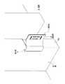
図1は、第1実施形態に係る袖看板の使用状態の一例を示した斜視図である。The best mode for carrying out the present invention will be described in detail with reference to the drawings. In the description, the same elements are denoted by the same reference numerals, and redundant description is omitted.
FIG. 1 is a perspective view showing an example of a use state of a sleeve signboard according to the first embodiment.
図1に示すように、第1実施形態に係る袖看板1は、壁Wの端部Waや柱などの取付対象物に着脱可能に取り付けられて使用される看板であり、例えば、工事現場における注意喚起のための看板として用いられている。第1実施形態では、袖看板1は、壁Wの端部Waから通路S上に張り出して設置されている。
袖看板1は、文字や図形などのメッセージが表示される看板部2と、看板部2を取付対象物に取り付けるための取付部3と、を有している。As shown in FIG. 1, a
The
図2は、取付対象物から袖看板を取り外した状態を示した斜視図である。なお、図2においては、説明の便宜のため、看板部2の一部を取付部3から離して描いている。
図2に示すように、看板部2は、2つの板状部材21,21を接着剤や両面粘着テープなどで互いに内面の一部を貼り合わせて形成されている。板状部材21は、例えば、文字や図形を記載した2枚の紙をラミネートフィルムでそれぞれコーティングしたものなどで構成されている。2つの板状部材21,21の取付部3側の内面21aは互いに貼り合わされておらず、二股形状に分かれており、例えば図2に示すように、両面テープ4によって取付部3に固定されている。なお、取付部3への2つの板状部材21,21の固定は、特に限定されるものではなく、リベットなど物理的な方法でもよい。FIG. 2 is a perspective view showing a state where the sleeve signboard is removed from the attachment object. In FIG. 2, a part of the
As shown in FIG. 2, the
取付部3は、例えば発泡樹脂などの弾性変形可能な材料で構成された部材である。第1実施形態の取付部3は、例えば建物の壁の端部や柱の周囲を保護するための養生材を短く切断して形成されている。 The
取付部3について、図3を参照して詳しく説明する。図3は、袖看板の平面図である。
図3に示すように、取付部3は、互いに対向して配置される一対の把持部31,31と、一対の把持部31,31の基端部31a,31a同士を連結する連結部32と、から構成されている。一対の把持部31,31と連結部32は、例えば発泡樹脂で一体成形されている。
各把持部31は、連結部32の両側から看板部2と反対方向にやや外向きに延出したのち、内向きに湾曲している。そして、各把持部31の先端部31bは、略直線状に形成され、連結部32と略直交する向きに延在している。各把持部31の先端部31b同士は、並列に配置されており、その間にはスリット33が形成されている。この一対の把持部31の間に取付対象物が配置される。
把持部31は、弾性変形可能な部材で構成されているので、把持部31,31同士の間隔を広げると、間隔を元に戻そうとする復元力が作用するようになっている。The
As shown in FIG. 3, the
Each
Since the
つづいて、第1実施形態に係る袖看板1の使用方法について図4を参照して説明する。図4は、袖看板を取付対象物に取り付ける手順を説明するための平面図であり、(a)は取付前の状態、(b)は取付後の状態をそれぞれ示している。 It continues and the usage method of the
はじめに、図4(a)に示すように、一対の把持部31,31同士の間隔を、取付対象物である壁Wの端部Waの幅寸法よりも大きく広げる。具体的には、略U字状に湾曲した状態にある一対の把持部31,31を、略L字状となるように変形させる。これにより、把持部31,31の先端部31b,31b同士の間隔が、端部Waの幅寸法よりも大きくなる。 First, as shown to Fig.4 (a), the space | interval of a pair of
次に、図4(b)に示すように、把持部31,31同士の間隔を広げた状態で取付部3を壁Wの端部Waに被せることにより、一対の把持部31,31によって壁Wを挟み込む。一対の把持部31,31は、湾曲した状態に戻ろうとするので、この復元力で壁Wを把持することとなる。これにより、袖看板1は、壁Wの端部Waに取り付けられた状態となる。 Next, as shown in FIG. 4 (b), the
このように、第1実施形態に係る袖看板1によれば、互いに対向して配置される一対の把持部31,31が、壁Wを復元力で把持するように構成されているので、弾性部材で形成された一対の把持部31,31を広げて壁Wを挟むという簡易な動作で、袖看板1を壁Wの端部Waに容易に取り付けることができる。また、一対の把持部31,31を広げるだけで袖看板1を壁Wから容易に取り外すことができる。 As described above, according to the
また、一対の把持部31,31は、発泡樹脂で構成されているので、自重が小さい。そのため、比較的小さな復元力(把持力)で、袖看板1を壁Wから張り出した状態に支持することができる。また、袖看板1は、壁Wから張り出した状態で支持されているので、離れた位置からでも良好に視認することができるとともに、通行の妨げになることがない。
また、自重が小さい(軽い)ので、持ち運びが容易であり、仮に落下したとしても怪我しない。また、看板部2をフィルムでコーティングした紙で形成すれば、容易に変形するので、ぶつかっても怪我をすることが無い。Moreover, since a pair of holding |
In addition, since its own weight is small (light), it is easy to carry and will not be injured even if it falls. Further, if the
つづいて、第2実施形態に係る袖看板1Aについて、図5を参照して説明する。なお、第1実施形態と同一の要素については同一の符号を付し、重複する説明は省略する。
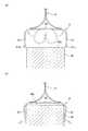
図5は、第2実施形態に係る袖看板を示す図面であり、(a)は取付対象物に取り付けていない状態を示す斜視図、(b)は取付対象物に取り付けた状態を示す平面図、である。Next, a
FIG. 5 is a drawing showing a sleeve signboard according to the second embodiment, where (a) is a perspective view showing a state where the sleeve is not attached to an attachment object, and (b) is a plan view showing a state where the sleeve is attached to the attachment object. .
図5(a),(b)に示すように、第2実施形態に係る袖看板1Aは、一対の把持部31,31の他方の端部同士を係脱可能に連結する留め具5,5を備えている点が、第1実施形態と異なっている。 As shown in FIGS. 5A and 5B, the
留め具5は、図5(a)に示すように、一対の把持部31,31のうち、連結部32と反対側に位置する湾曲した部分に、上下に離間して2箇所に設けられている。
留め具5は、一対の把持部31,31の湾曲した部分にそれぞれ突設された一対の円柱状の軸部51,51と、各軸部51,51の先端側にそれぞれ取り付けられた円盤状の係止部52,52と、一対の軸部51,51の係止部52よりも把持部31側に巻き付けられた留め紐53と、から構成されている。留め紐53の一方の端部は、一対の軸部51,51のうちの一方に固定されている。As shown in FIG. 5 (a), the
The
図5(b)に示すように、取付対象物である円柱状の柱Hに袖看板1Aを取り付ける場合には、一対の把持部31,31を広げて柱Hを両側から包むように把持したのち、一対の軸部51の間に留め紐53を巻きつける。
これにより、把持部31,31同士の間隔が開くことがなくなるため、袖看板1Aが風などによって脱落することがない。As shown in FIG. 5 (b), when attaching the
Thereby, since the space | interval of the holding
つづいて、第3実施形態に係る袖看板1Bについて、図6を参照して説明する。説明において、第1及び第2実施形態と同一の要素には同一の符号を付し、重複する説明は省略する。
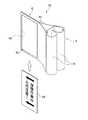
図6は、第3実施形態に係る袖看板の斜視図である。
図6に示すように、第3実施形態に係る袖看板1Bは、看板部6が中空状に構成されている点が、第1実施形態と異なっている。Subsequently, a
FIG. 6 is a perspective view of a sleeve signboard according to the third embodiment.
As shown in FIG. 6, the
看板部6は、2枚の板状部材61を接着剤や溶着などで中空部62を形成するように貼り合わされている。2つの板状部材61,61の取付部3側の内面21aは互いに貼り合わされておらず、二股形状に分かれており、取付部3に固定されている。
中空部62には、図形や文字を記載したプレート64を格納する。中空部62は、雨水などが入り込まないように、下向きに開口している。中空部62の開口部にはチャック63が設けられており、開口部を開閉できるようになっている。
プレート64は、図形や文字を記載した板状の部材であり、例えば紙やプラスチックフィルムなどで形成されている。The sign part 6 is bonded together so that two plate-
The
The
第3実施形態に係る袖看板1Bによれば、看板部6にプレート64を格納するための中空部62が設けられているので、異なる図形や文字を記載したプレート64を複数用意しておけば、目的に合わせてプレート64を自在に交換することができる。そのため、一つの袖看板1Bを複数の用途に使用することができる。 According to the
以上、本発明を実施するための最良の実施形態について、図面を参照して詳細に説明したが、本発明はこれらの実施形態に限定されるものではなく、発明の主旨を逸脱しない範囲で適宜変更が可能である。 As mentioned above, although the best embodiment for implementing this invention was described in detail with reference to drawings, this invention is not limited to these embodiment, In the range which does not deviate from the main point of invention, it is appropriate. It can be changed.
例えば、取付部3の形状は、取付対象物を挟むことが可能であればどのような形状でも良い。ここで、取付部3の変形例について図7を参照して説明する。
図7(a)は、第1変形例を示す平面図であり、(b)は第2変形例を示す平面図である。For example, the shape of the
Fig.7 (a) is a top view which shows a 1st modification, (b) is a top view which shows a 2nd modification.
図7(a)に示すように、第1変形例に係る取付部3Aは、略直線状に形成された一対の把持部31A,31Aを有している。一対の把持部31A,31Aは、連結部32の両端部から、看板部2と反対方向に内向きに延出している。
このような取付部3Aによれば、比較的幅の狭い取付対象物を把持することができる。As shown in FIG. 7A, the
According to such an
図7(b)に示すように、第2変形例に係る取付部3Bは、略U字状に形成された一対の把持部31B,31Bを有している。一対の把持部31Bは、連結部32の両端から連結部32と略平行に延出したのち、略180度湾曲し、さらに連結部32の中央部付近まで延出している。
このような取付部3Bによれば、比較的幅の広い取付対象物を把持することができる。As shown in FIG. 7B, the
According to such an
また、一対の把持部31,31の材質は、取付対象物を復元力で把持可能であれば、発泡樹脂に限定されるものではなく、例えば金属製薄板で構成されていてもよいし、金属製薄板を補助的に併用してもよい。 Further, the material of the pair of
1 袖看板
2 看板部
3 取付部
31 把持部
32 連結部DESCRIPTION OF
Claims (3)
Translated fromJapanese互いに対向して配置される一対の把持部と、前記一対の把持部の一方の端部同士を連結する連結部と、前記把持部及び前記連結部の少なくとも一方に固定された看板部と、を有し、
前記一対の把持部の間隔を広げて前記取付対象物を挟み、前記一対の把持部の復元力で前記取付対象物を把持するとともに、
前記看板部は、一端側が二股状に分かれた変形可能な部材で構成され、前記二股状に分かれた部分で前記把持部及び前記連結部の少なくとも一方を両側から挟むように固定されている
ことを特徴とする袖看板。It is a sleeve signboard installed in a state of overhanging from the object to be installed,
A pair of gripping portions disposed opposite to each other, a connecting portion for connecting one end portions of the pair of gripping portions, and a signboard portion fixed to at least one of the gripping portion and the connecting portion, Have
While widening the gap between the pair of gripping parts to sandwich the attachment object, gripping the attachment object with the restoring force of the pair of gripping parts,
The signboard portion is composed of a deformable member having one end side divided into a forked shape, and is fixed so that at least one of the gripping portion and the connecting portion is sandwiched from both sides by the forked portion. Characteristic sleeve signboard.
前記留め具は、一対の把持部にそれぞれ突設された一対の軸部と、前記各軸部の先端側にそれぞれ取り付けられた係止部と、一端側が前記一対の軸部の一方に固定され、前記把持部を前記取付対象物に取り付けた状態で前記一対の軸部の前記係止部よりも前記把持部側に巻き付けられる留め紐と、から構成されている
ことを特徴とする請求項1に記載の袖看板。Have a fastener for connecting the other ends of the pair of grippingportions,
The fastener includes a pair of shaft portions projecting from a pair of gripping portions, a locking portion attached to a tip side of each shaft portion, and one end side fixed to one of the pair of shaft portions. , claim1, characterizedby being composed of the grip portion from the retaining cord which is wound around the grip portion side of the engaging portion of the pair of shaft portions in a state attached to the attaching object Sleeve signboardas described in.
Priority Applications (1)
| Application Number | Priority Date | Filing Date | Title |
|---|---|---|---|
| JP2008195494AJP5156524B2 (en) | 2008-07-29 | 2008-07-29 | Sleeve sign |
Applications Claiming Priority (1)
| Application Number | Priority Date | Filing Date | Title |
|---|---|---|---|
| JP2008195494AJP5156524B2 (en) | 2008-07-29 | 2008-07-29 | Sleeve sign |
Publications (2)
| Publication Number | Publication Date |
|---|---|
| JP2010032811A JP2010032811A (en) | 2010-02-12 |
| JP5156524B2true JP5156524B2 (en) | 2013-03-06 |
Family
ID=41737352
Family Applications (1)
| Application Number | Title | Priority Date | Filing Date |
|---|---|---|---|
| JP2008195494AExpired - Fee RelatedJP5156524B2 (en) | 2008-07-29 | 2008-07-29 | Sleeve sign |
Country Status (1)
| Country | Link |
|---|---|
| JP (1) | JP5156524B2 (en) |
Families Citing this family (2)
| Publication number | Priority date | Publication date | Assignee | Title |
|---|---|---|---|---|
| JP5277202B2 (en)* | 2010-05-25 | 2013-08-28 | 株式会社中国警備保障 | Standing signboard |
| CN111653191A (en)* | 2020-06-30 | 2020-09-11 | 芜湖鼎晨广告传媒有限公司 | Quick connect signage stand for construction sites |
Family Cites Families (8)
| Publication number | Priority date | Publication date | Assignee | Title |
|---|---|---|---|---|
| JPS4732623Y1 (en)* | 1968-02-19 | 1972-10-02 | ||
| JPS51103400U (en)* | 1975-02-17 | 1976-08-19 | ||
| JPS622080U (en)* | 1985-06-20 | 1987-01-08 | ||
| JPH0269374U (en)* | 1988-11-11 | 1990-05-25 | ||
| JP2927414B2 (en)* | 1997-05-27 | 1999-07-28 | 西日本ノバフォーム株式会社 | Building protection material, building protection method and human body protection method |
| JP3311713B2 (en)* | 1998-09-30 | 2002-08-05 | 株式会社ジエイエスピー | Protective layer |
| JP2002089046A (en)* | 2000-09-21 | 2002-03-27 | Sakai Kagaku Kogyo Kk | Protective material and manufacturing method therefor |
| JP4006462B1 (en)* | 2006-06-22 | 2007-11-14 | 善己 森田 | Display member set, mounting attachment used therefor, display member and display sheet |
- 2008
- 2008-07-29JPJP2008195494Apatent/JP5156524B2/ennot_activeExpired - Fee Related
Also Published As
| Publication number | Publication date |
|---|---|
| JP2010032811A (en) | 2010-02-12 |
Similar Documents
| Publication | Publication Date | Title |
|---|---|---|
| US5488198A (en) | Protection device for apertures in metal studs or panels | |
| JP5129994B2 (en) | Stretch release tape | |
| US10875691B1 (en) | Cable tie with multi-slot head for attachments | |
| JP2010531917A5 (en) | ||
| WO2005009280A3 (en) | Device for laceration or incision closure | |
| US7386928B1 (en) | Method for covering an edge of a sign | |
| JP5156524B2 (en) | Sleeve sign | |
| EP2319054B1 (en) | Cable attachment | |
| US9482263B2 (en) | Guide apparatuses for use with fasteners | |
| CA2330940A1 (en) | Rectangular panel fastener | |
| JP2013108626A (en) | Wiring and piping material supporting tool | |
| US20190156711A1 (en) | Display sign and method of disposing same | |
| JP2011241370A5 (en) | ||
| JP3130114U (en) | Fixtures such as telephone pole sign boards | |
| JP2015094778A (en) | Banner support tool | |
| JP2011052410A (en) | Marking implement | |
| JP2010246264A (en) | Wire harness fixture | |
| JP4458540B2 (en) | Power pole band | |
| JP6035411B2 (en) | Protective film with adhesive with separator | |
| JP3208957U (en) | Multifunctional cushioning material for cable ties | |
| JP6915287B2 (en) | RFID tag holder and sheet for RFID tag holder | |
| JP2005112336A (en) | Self-adhesive cover for adhering edge side | |
| JP4102808B2 (en) | Waterproofing member for corner and waterproof construction method for corner | |
| JP3211100U (en) | Cable ties | |
| WO2010054857A3 (en) | Marker tab for the reversible attachment to a corner of a page |
Legal Events
| Date | Code | Title | Description |
|---|---|---|---|
| A621 | Written request for application examination | Free format text:JAPANESE INTERMEDIATE CODE: A621 Effective date:20101214 | |
| A621 | Written request for application examination | Free format text:JAPANESE INTERMEDIATE CODE: A621 Effective date:20101214 | |
| A131 | Notification of reasons for refusal | Free format text:JAPANESE INTERMEDIATE CODE: A131 Effective date:20120417 | |
| A977 | Report on retrieval | Free format text:JAPANESE INTERMEDIATE CODE: A971007 Effective date:20120419 | |
| A521 | Written amendment | Free format text:JAPANESE INTERMEDIATE CODE: A523 Effective date:20120511 | |
| TRDD | Decision of grant or rejection written | ||
| A01 | Written decision to grant a patent or to grant a registration (utility model) | Free format text:JAPANESE INTERMEDIATE CODE: A01 Effective date:20121204 | |
| A61 | First payment of annual fees (during grant procedure) | Free format text:JAPANESE INTERMEDIATE CODE: A61 Effective date:20121210 | |
| FPAY | Renewal fee payment (event date is renewal date of database) | Free format text:PAYMENT UNTIL: 20181214 Year of fee payment:6 | |
| R150 | Certificate of patent or registration of utility model | Ref document number:5156524 Country of ref document:JP Free format text:JAPANESE INTERMEDIATE CODE: R150 Free format text:JAPANESE INTERMEDIATE CODE: R150 | |
| LAPS | Cancellation because of no payment of annual fees |