JP5155273B2 - MRI induction thermosurgical instrument - Google Patents
MRI induction thermosurgical instrumentDownload PDFInfo
- Publication number
- JP5155273B2 JP5155273B2JP2009224862AJP2009224862AJP5155273B2JP 5155273 B2JP5155273 B2JP 5155273B2JP 2009224862 AJP2009224862 AJP 2009224862AJP 2009224862 AJP2009224862 AJP 2009224862AJP 5155273 B2JP5155273 B2JP 5155273B2
- Authority
- JP
- Japan
- Prior art keywords
- optical fiber
- axis
- probe
- temperature
- fiber
- Prior art date
- Legal status (The legal status is an assumption and is not a legal conclusion. Google has not performed a legal analysis and makes no representation as to the accuracy of the status listed.)
- Expired - Fee Related
Links
- 230000006698inductionEffects0.000titledescription2
- 238000010438heat treatmentMethods0.000claimsabstractdescription41
- 239000000523sampleSubstances0.000claimsabstractdescription33
- 238000001816coolingMethods0.000claimsabstractdescription10
- 230000003287optical effectEffects0.000claimsabstractdescription9
- 230000003014reinforcing effectEffects0.000claimsabstractdescription5
- 239000013307optical fiberSubstances0.000claimsdescription146
- 238000003780insertionMethods0.000claimsdescription8
- 230000037431insertionEffects0.000claimsdescription8
- 230000008859changeEffects0.000claimsdescription6
- 230000009471actionEffects0.000claimsdescription4
- 230000001225therapeutic effectEffects0.000claims1
- 206010028980NeoplasmDiseases0.000abstractdescription71
- 238000002595magnetic resonance imagingMethods0.000abstractdescription30
- 239000000835fiberSubstances0.000abstractdescription20
- 239000000463materialSubstances0.000abstractdescription11
- 206010020843HyperthermiaDiseases0.000abstractdescription6
- 230000036031hyperthermiaEffects0.000abstractdescription6
- RTAQQCXQSZGOHL-UHFFFAOYSA-NTitaniumChemical compound[Ti]RTAQQCXQSZGOHL-UHFFFAOYSA-N0.000abstractdescription3
- 229910052719titaniumInorganic materials0.000abstractdescription3
- 239000010936titaniumSubstances0.000abstractdescription3
- 239000012809cooling fluidSubstances0.000abstractdescription2
- 230000002977hyperthermial effectEffects0.000abstract1
- 210000001519tissueAnatomy0.000description21
- 238000001356surgical procedureMethods0.000description20
- 230000005855radiationEffects0.000description19
- 238000000034methodMethods0.000description15
- 230000005291magnetic effectEffects0.000description12
- 238000009833condensationMethods0.000description9
- 230000005494condensationEffects0.000description9
- 230000001276controlling effectEffects0.000description9
- 230000000694effectsEffects0.000description9
- 238000000015thermotherapyMethods0.000description8
- 239000004020conductorSubstances0.000description7
- 238000005452bendingMethods0.000description6
- 239000002775capsuleSubstances0.000description6
- 238000001514detection methodMethods0.000description6
- 201000011510cancerDiseases0.000description5
- 239000011521glassSubstances0.000description5
- 230000002093peripheral effectEffects0.000description5
- 238000009529body temperature measurementMethods0.000description4
- 239000002826coolantSubstances0.000description4
- 239000000110cooling liquidSubstances0.000description4
- 230000005294ferromagnetic effectEffects0.000description4
- 238000002647laser therapyMethods0.000description4
- 239000007788liquidSubstances0.000description4
- 238000011084recoveryMethods0.000description4
- IJGRMHOSHXDMSA-UHFFFAOYSA-NAtomic nitrogenChemical compoundN#NIJGRMHOSHXDMSA-UHFFFAOYSA-N0.000description3
- 210000004556brainAnatomy0.000description3
- 239000013078crystalSubstances0.000description3
- 238000010586diagramMethods0.000description3
- 239000007789gasSubstances0.000description3
- 230000006872improvementEffects0.000description3
- 238000013021overheatingMethods0.000description3
- 229920002430Fibre-reinforced plasticPolymers0.000description2
- 238000003763carbonizationMethods0.000description2
- 239000000919ceramicSubstances0.000description2
- 239000011151fibre-reinforced plasticSubstances0.000description2
- 239000003365glass fiberSubstances0.000description2
- 230000036541healthEffects0.000description2
- 238000003384imaging methodMethods0.000description2
- 238000005259measurementMethods0.000description2
- 239000003507refrigerantSubstances0.000description2
- 238000002560therapeutic procedureMethods0.000description2
- 238000003325tomographyMethods0.000description2
- 208000003174Brain NeoplasmsDiseases0.000description1
- 229920000106Liquid crystal polymerPolymers0.000description1
- 239000004977Liquid-crystal polymers (LCPs)Substances0.000description1
- 208000027418Wounds and injuryDiseases0.000description1
- 210000004204blood vesselAnatomy0.000description1
- 238000007796conventional methodMethods0.000description1
- 229910001873dinitrogenInorganic materials0.000description1
- 201000010099diseaseDiseases0.000description1
- 208000037265diseases, disorders, signs and symptomsDiseases0.000description1
- 239000006185dispersionSubstances0.000description1
- 238000002474experimental methodMethods0.000description1
- 238000013383initial experimentMethods0.000description1
- 230000001678irradiating effectEffects0.000description1
- 230000001788irregularEffects0.000description1
- 238000002430laser surgeryMethods0.000description1
- 238000000691measurement methodMethods0.000description1
- 238000000465mouldingMethods0.000description1
- 229910052757nitrogenInorganic materials0.000description1
- NJPPVKZQTLUDBO-UHFFFAOYSA-NnovaluronChemical compoundC1=C(Cl)C(OC(F)(F)C(OC(F)(F)F)F)=CC=C1NC(=O)NC(=O)C1=C(F)C=CC=C1FNJPPVKZQTLUDBO-UHFFFAOYSA-N0.000description1
- 230000000704physical effectEffects0.000description1
- 239000004033plasticSubstances0.000description1
- 229920003023plasticPolymers0.000description1
- 239000010453quartzSubstances0.000description1
- 238000005057refrigerationMethods0.000description1
- 230000035939shockEffects0.000description1
- VYPSYNLAJGMNEJ-UHFFFAOYSA-Nsilicon dioxideInorganic materialsO=[Si]=OVYPSYNLAJGMNEJ-UHFFFAOYSA-N0.000description1
- 210000003625skullAnatomy0.000description1
- 238000012546transferMethods0.000description1
- 239000012780transparent materialSubstances0.000description1
- 238000002604ultrasonographyMethods0.000description1
Images


Classifications
- A—HUMAN NECESSITIES
- A61—MEDICAL OR VETERINARY SCIENCE; HYGIENE
- A61B—DIAGNOSIS; SURGERY; IDENTIFICATION
- A61B18/00—Surgical instruments, devices or methods for transferring non-mechanical forms of energy to or from the body
- A61B18/18—Surgical instruments, devices or methods for transferring non-mechanical forms of energy to or from the body by applying electromagnetic radiation, e.g. microwaves
- A61B18/20—Surgical instruments, devices or methods for transferring non-mechanical forms of energy to or from the body by applying electromagnetic radiation, e.g. microwaves using laser
- A61B18/22—Surgical instruments, devices or methods for transferring non-mechanical forms of energy to or from the body by applying electromagnetic radiation, e.g. microwaves using laser the beam being directed along or through a flexible conduit, e.g. an optical fibre; Couplings or hand-pieces therefor
- A61B18/24—Surgical instruments, devices or methods for transferring non-mechanical forms of energy to or from the body by applying electromagnetic radiation, e.g. microwaves using laser the beam being directed along or through a flexible conduit, e.g. an optical fibre; Couplings or hand-pieces therefor with a catheter
- A—HUMAN NECESSITIES
- A61—MEDICAL OR VETERINARY SCIENCE; HYGIENE
- A61B—DIAGNOSIS; SURGERY; IDENTIFICATION
- A61B5/00—Measuring for diagnostic purposes; Identification of persons
- A61B5/05—Detecting, measuring or recording for diagnosis by means of electric currents or magnetic fields; Measuring using microwaves or radio waves
- A61B5/055—Detecting, measuring or recording for diagnosis by means of electric currents or magnetic fields; Measuring using microwaves or radio waves involving electronic [EMR] or nuclear [NMR] magnetic resonance, e.g. magnetic resonance imaging
- A—HUMAN NECESSITIES
- A61—MEDICAL OR VETERINARY SCIENCE; HYGIENE
- A61B—DIAGNOSIS; SURGERY; IDENTIFICATION
- A61B90/00—Instruments, implements or accessories specially adapted for surgery or diagnosis and not covered by any of the groups A61B1/00 - A61B50/00, e.g. for luxation treatment or for protecting wound edges
- A61B90/36—Image-producing devices or illumination devices not otherwise provided for
- A—HUMAN NECESSITIES
- A61—MEDICAL OR VETERINARY SCIENCE; HYGIENE
- A61B—DIAGNOSIS; SURGERY; IDENTIFICATION
- A61B18/00—Surgical instruments, devices or methods for transferring non-mechanical forms of energy to or from the body
- A61B18/18—Surgical instruments, devices or methods for transferring non-mechanical forms of energy to or from the body by applying electromagnetic radiation, e.g. microwaves
- A61B18/20—Surgical instruments, devices or methods for transferring non-mechanical forms of energy to or from the body by applying electromagnetic radiation, e.g. microwaves using laser
- A—HUMAN NECESSITIES
- A61—MEDICAL OR VETERINARY SCIENCE; HYGIENE
- A61B—DIAGNOSIS; SURGERY; IDENTIFICATION
- A61B18/00—Surgical instruments, devices or methods for transferring non-mechanical forms of energy to or from the body
- A61B2018/00005—Cooling or heating of the probe or tissue immediately surrounding the probe
- A61B2018/00011—Cooling or heating of the probe or tissue immediately surrounding the probe with fluids
- A61B2018/00023—Cooling or heating of the probe or tissue immediately surrounding the probe with fluids closed, i.e. without wound contact by the fluid
- A—HUMAN NECESSITIES
- A61—MEDICAL OR VETERINARY SCIENCE; HYGIENE
- A61B—DIAGNOSIS; SURGERY; IDENTIFICATION
- A61B18/00—Surgical instruments, devices or methods for transferring non-mechanical forms of energy to or from the body
- A61B2018/00053—Mechanical features of the instrument of device
- A61B2018/00184—Moving parts
- A61B2018/00196—Moving parts reciprocating lengthwise
- A—HUMAN NECESSITIES
- A61—MEDICAL OR VETERINARY SCIENCE; HYGIENE
- A61B—DIAGNOSIS; SURGERY; IDENTIFICATION
- A61B18/00—Surgical instruments, devices or methods for transferring non-mechanical forms of energy to or from the body
- A61B2018/00636—Sensing and controlling the application of energy
- A—HUMAN NECESSITIES
- A61—MEDICAL OR VETERINARY SCIENCE; HYGIENE
- A61B—DIAGNOSIS; SURGERY; IDENTIFICATION
- A61B18/00—Surgical instruments, devices or methods for transferring non-mechanical forms of energy to or from the body
- A61B18/18—Surgical instruments, devices or methods for transferring non-mechanical forms of energy to or from the body by applying electromagnetic radiation, e.g. microwaves
- A61B18/1815—Surgical instruments, devices or methods for transferring non-mechanical forms of energy to or from the body by applying electromagnetic radiation, e.g. microwaves using microwaves
- A61B2018/1861—Surgical instruments, devices or methods for transferring non-mechanical forms of energy to or from the body by applying electromagnetic radiation, e.g. microwaves using microwaves with an instrument inserted into a body lumen or cavity, e.g. a catheter
- A—HUMAN NECESSITIES
- A61—MEDICAL OR VETERINARY SCIENCE; HYGIENE
- A61B—DIAGNOSIS; SURGERY; IDENTIFICATION
- A61B18/00—Surgical instruments, devices or methods for transferring non-mechanical forms of energy to or from the body
- A61B18/18—Surgical instruments, devices or methods for transferring non-mechanical forms of energy to or from the body by applying electromagnetic radiation, e.g. microwaves
- A61B18/20—Surgical instruments, devices or methods for transferring non-mechanical forms of energy to or from the body by applying electromagnetic radiation, e.g. microwaves using laser
- A61B2018/2005—Surgical instruments, devices or methods for transferring non-mechanical forms of energy to or from the body by applying electromagnetic radiation, e.g. microwaves using laser with beam delivery through an interstitially insertable device, e.g. needle
- A—HUMAN NECESSITIES
- A61—MEDICAL OR VETERINARY SCIENCE; HYGIENE
- A61B—DIAGNOSIS; SURGERY; IDENTIFICATION
- A61B18/00—Surgical instruments, devices or methods for transferring non-mechanical forms of energy to or from the body
- A61B18/18—Surgical instruments, devices or methods for transferring non-mechanical forms of energy to or from the body by applying electromagnetic radiation, e.g. microwaves
- A61B18/20—Surgical instruments, devices or methods for transferring non-mechanical forms of energy to or from the body by applying electromagnetic radiation, e.g. microwaves using laser
- A61B18/22—Surgical instruments, devices or methods for transferring non-mechanical forms of energy to or from the body by applying electromagnetic radiation, e.g. microwaves using laser the beam being directed along or through a flexible conduit, e.g. an optical fibre; Couplings or hand-pieces therefor
- A61B2018/2255—Optical elements at the distal end of probe tips
- A61B2018/2272—Optical elements at the distal end of probe tips with reflective or refractive surfaces for deflecting the beam
- A61B2018/2277—Optical elements at the distal end of probe tips with reflective or refractive surfaces for deflecting the beam with refractive surfaces
- A—HUMAN NECESSITIES
- A61—MEDICAL OR VETERINARY SCIENCE; HYGIENE
- A61B—DIAGNOSIS; SURGERY; IDENTIFICATION
- A61B90/00—Instruments, implements or accessories specially adapted for surgery or diagnosis and not covered by any of the groups A61B1/00 - A61B50/00, e.g. for luxation treatment or for protecting wound edges
- A61B90/36—Image-producing devices or illumination devices not otherwise provided for
- A61B90/37—Surgical systems with images on a monitor during operation
- A61B2090/374—NMR or MRI
Landscapes
- Health & Medical Sciences (AREA)
- Life Sciences & Earth Sciences (AREA)
- Surgery (AREA)
- Physics & Mathematics (AREA)
- Nuclear Medicine, Radiotherapy & Molecular Imaging (AREA)
- Molecular Biology (AREA)
- Veterinary Medicine (AREA)
- Public Health (AREA)
- Engineering & Computer Science (AREA)
- Biomedical Technology (AREA)
- Heart & Thoracic Surgery (AREA)
- Medical Informatics (AREA)
- General Health & Medical Sciences (AREA)
- Animal Behavior & Ethology (AREA)
- Pathology (AREA)
- Optics & Photonics (AREA)
- Electromagnetism (AREA)
- Otolaryngology (AREA)
- Oral & Maxillofacial Surgery (AREA)
- Radiology & Medical Imaging (AREA)
- High Energy & Nuclear Physics (AREA)
- Biophysics (AREA)
- Laser Surgery Devices (AREA)
- Radiation-Therapy Devices (AREA)
- Magnetic Resonance Imaging Apparatus (AREA)
- Thermotherapy And Cooling Therapy Devices (AREA)
- Medicines Containing Antibodies Or Antigens For Use As Internal Diagnostic Agents (AREA)
Abstract
Description
Translated fromJapanese本発明は、磁気共鳴映像法を用いて熱源の誘導、制御を行う、温熱療法による患部の手術のための器械に関する。 The present invention relates to an instrument for surgery of an affected area by hyperthermia, which performs induction and control of a heat source using magnetic resonance imaging.
腫瘍の温熱手術法は公知である。これによって、組織を55℃以上の既定の温度で加熱することによって、加熱された組織を凝結させることで、悪性腫瘍やその他の腫瘍を治療できる。望ましい温度の範囲は55℃から65℃の範囲内で、組織の炭化や剥離が起こらない温度とする。 Tumor hyperthermia is well known. Thus, by heating the tissue at a predetermined temperature of 55 ° C. or higher, the heated tissue can be coagulated to treat a malignant tumor or other tumors. A desirable temperature range is within a range of 55 ° C. to 65 ° C., and a temperature at which no carbonization or peeling of the tissue occurs.
加熱の手法のひとつは、対象となる腫瘍に、光ファイバーを挿入することで行う。該光ファイバーは挿入する側の端部に、外部の光源からのレーザー光を該光ファイバーの長手方向に直角な方向へと切り替える装置を備えるものとする。そして、レーザーからのエネルギーは、該端部の周囲の組織へと放射され、加熱を行う。該エネルギーは比較的浅い角度に制限されたビームによって方向を決められるので、該光ファイバーを回動させることによって、ビームが該光ファイバーの軸のまわりを回動し、該腫瘍の該光ファイバー周囲の部分が全て加熱される。そして、該光ファイバーを縦方向に移動させ、回動させることで、該腫瘍付近の組織に有意な影響を与えることなく、該腫瘍全体を既定の温度まで加熱することができる。 One method of heating is performed by inserting an optical fiber into the target tumor. The optical fiber is provided with a device for switching laser light from an external light source in a direction perpendicular to the longitudinal direction of the optical fiber at the end on the insertion side. Then, the energy from the laser is radiated to the tissue around the end, and heating is performed. Since the energy is directed by a beam constrained to a relatively shallow angle, rotating the optical fiber causes the beam to rotate about the axis of the optical fiber so that the portion of the tumor surrounding the optical fiber is All are heated. Then, by moving the optical fiber in the vertical direction and rotating it, the entire tumor can be heated to a predetermined temperature without significantly affecting the tissue in the vicinity of the tumor.
この時、該光ファイバーの操作は、解剖学の知識や腫瘍の位置に関する情報を利用できず、誘導がほとんど、或いは全く得られない状況で行われる。したがって、周囲の組織の損傷を最低限に抑えつつ、腫瘍の全体を加熱することは困難である。 At this time, the operation of the optical fiber is performed in a situation where little or no guidance can be obtained because anatomical knowledge and information regarding the position of the tumor cannot be used. Therefore, it is difficult to heat the entire tumor while minimizing damage to surrounding tissue.
磁気共鳴映像法を用いることで、除去すべき悪性腫瘍及びその他の腫瘍の位置を測定できることが一般に知られている。しかし、手術において該映像法を、除去すべき腫瘍の加熱の制御に用いるための手法は存在していなかった。多くの場合、手術の開始前に該映像法を用いるので、除去あるいは凝結させるべき組織が移動し、除去する腫瘍の位置が著しく変化する可能性があった。これにより、手術の精度が低下することとなっていた。 It is generally known that the location of malignant tumors and other tumors to be removed can be measured by using magnetic resonance imaging. However, there has been no technique for using the imaging method in surgery to control the heating of the tumor to be removed. In many cases, since the imaging method is used before the start of surgery, the tissue to be removed or coagulated may move, and the position of the removed tumor may change significantly. As a result, the accuracy of surgery has been reduced.
また、磁気共鳴映像法を用い、連続した映像を修正することで、映像中の組織の温度と、温度の時間による変化を測定できることが知られている。 In addition, it is known that the temperature of a tissue in an image and a change with time of the temperature can be measured by correcting consecutive images using magnetic resonance imaging.
米国保健社会福祉省に譲渡され、1990年4月3日に発行された米国特許第4914608号(発明者ルビアハン)では、組織中の温度を測定する方法が示されている。 U.S. Pat. No. 4,914,608 (inventor Rubiahan), assigned to the US Department of Health and Human Services and issued on April 3, 1990, shows a method for measuring temperature in tissue.
米国保健社会福祉省に譲渡され、1994年2月8日に発行された米国特許第5284144号(発明者デランノイ)では、磁気共鳴映像法に用いるコイル内に、外部からの非侵襲性の加熱手段を備えた、癌の温熱療法用器械が示されている。この開示内容は推論的で、外部からの加熱手段における、温度のMRI測定の実現性についての初期実験に関するものである。該特許発明の開示内容は、商業的に実施可能な温熱療法による手術システムへの導入には至っていない。 In US Pat. No. 5,284,144 (inventor Delan Noy), assigned to the US Department of Health and Human Services and issued on February 8, 1994, a non-invasive heating means is provided in the coil used for magnetic resonance imaging. An instrument for cancer hyperthermia is shown. This disclosure is speculative and relates to initial experiments on the feasibility of temperature MRI measurements in external heating means. The disclosure of the patented invention has not led to introduction into a commercially feasible thermotherapy surgical system.
米国ゼネラル・エレクトリック社に譲渡された米国特許第5368031号及び第5291890号は、所定の熱分布を熱源により生成し、該熱分布が予想された値に従うことを確認するために測定を行うことで、加熱すべき領域全体を加熱するためのMRI制御による加熱手法に関するものである。該特許発明による器械も、商業的に実施可能な温熱療法による手術手法となるものではない。 U.S. Pat. Nos. 5,368,081 and 5,291,890, assigned to General Electric Company, USA, generate a predetermined heat distribution with a heat source and perform measurements to confirm that the heat distribution conforms to expected values. The present invention relates to a heating technique based on MRI control for heating the entire region to be heated. The instrument according to the patented invention is not a commercially available thermotherapy surgical technique.
癌・腫瘍類似疾患記念病院に譲渡され、1987年7月9日に発行された、初期の米国特許第4671254号(発明者フェアー)では、腫瘍を衝撃波にさらすことによる非外科的な腫瘍の療法が示されている。該療法では、効果の測定と制御のための測定手法を用いていない。 Early US Pat. No. 4,671,254 (Inventor Fair), assigned to the Cancer-Tumor Similar Disease Memorial Hospital and issued on July 9, 1987, discloses non-surgical tumor therapy by exposing the tumor to shock waves. It is shown. The therapy does not use measurement techniques for measuring and controlling effects.
1998年10月20日に発行され、譲渡されていない米国特許第5823941号(発明者ショーンジー)では、光エネルギーを放射し、縦方向の移動と回動によって該エネルギーの方向を定める光ファイバーを支持するように、特別に改良された内視鏡が示されている。この装置は腫瘍の除去に用いるもので、除去すべき腫瘍を蒸発させるのに充分なエネルギーを放射するとともに、それによって生じたガスを内視鏡より吸引して除去するものである。MRIによって該腫瘍の画像を得、これによって、手術中における該光ファイバーの移動経路を決めている。移動操作中にはフィードバックはなく、操作は事前の解析のみに依存して行われるものである。該装置は、商業的、医療目的での利用が可能なものではない。 US Pat. No. 5,823,441 (inventor Shaunji), issued October 20, 1998 and not assigned, supports optical fiber that emits light energy and defines the direction of the energy by longitudinal movement and rotation. As such, a specially improved endoscope is shown. This device is used for removing a tumor. The device emits sufficient energy to evaporate the tumor to be removed, and gas generated thereby is sucked and removed from an endoscope. An image of the tumor is obtained by MRI, thereby determining the path of movement of the optical fiber during surgery. There is no feedback during the move operation, and the operation is performed only by prior analysis. The device cannot be used for commercial and medical purposes.
ボストン・サイエンティフィック社に譲渡され、1995年10月3日に発行された米国特許第5454807号(発明者レノックス)では、深部の組織へ放射するエネルギーの増加を可能とするために、組織表面を冷却し損傷を防ぐための冷却液を供給する管を光ファイバーとともに備えた、該光ファイバーによる腫瘍への光エネルギー照射のための装置が示されている。しかし該装置は加熱の結果のフィードバックによる制御を行えるものではない。 In U.S. Pat. No. 5,454,807 (inventor Lennox), assigned to Boston Scientific and issued on October 3, 1995, a tissue surface was formed to allow for increased energy radiating into deep tissue. An apparatus for irradiating light energy to a tumor by means of an optical fiber is shown, which is provided with a tube for supplying a cooling liquid for cooling and preventing damage. However, this device cannot be controlled by feedback of the heating result.
MRCシステムズ有限責任会社に譲渡され、1996年7月28日に発行された米国特許第5785704号(発明者ビル)では脳腫瘍への放射のためのレーザービームとレンズを有する装置が示されるが、エネルギーのフィードバック制御の手法は示されていない。該装置は光破断効果を得るために高速パルスレーザーエネルギーを用いる。 US Pat. No. 5,785,704 (Inventor Building), assigned to MRC Systems Limited Company and issued July 28, 1996, shows a device having a laser beam and lens for radiation to a brain tumor. The feedback control method is not shown. The apparatus uses high speed pulsed laser energy to obtain a photobreaking effect.
カーンらがジャーナル・オブ・コンピュータ・アシステッド・トモグラフィ誌1994年7・8月号18(4)の519頁から532頁、及びジャーナル・オブ・マグネティック・レゾナンス・イメージングJMRI誌1998年8号の160頁から164頁において、またフォーグルらがラジオロジー誌1998年209号の381頁から385頁において、光ファイバーを経由したレーザーの熱エネルギーを腫瘍に放射し、またエネルギーの放射中の腫瘍周辺の温度をMRIによって測定する手法を示している。しかしこれらの論文のいずれにおいても、温度の測定からのフィードバックによりエネルギーを制御する手法については述べられていない。また、フォーグルの論文においては、ドイツ、ベルリンのソマテックス社から商品として供給される、プローブの端部において組織の冷却を行う冷却手法が示されている。該装置は、アウターチューブ、及び該アウターチューブ内に配設され、内部に光ファイバーが通されたインナーチューブから構成され、冷却液が該アウターチューブと該インナーチューブの間、及び該インナーチューブの内部を連続的に流されるものである。 Kahn et al., Journal of Computer Assisted Tomography, July August 1994, 18 (4), pages 519 to 532, and Journal of Magnetic Resonance Imaging, JMRI, 1998, No. 160, 160. In pages 164 to 164, and Foggler et al. In Radiology magazine 1998 209, pages 381 to 385, the thermal energy of the laser via the optical fiber is emitted to the tumor, and the temperature around the tumor during the emission of energy is measured. A method for measuring by MRI is shown. However, none of these papers describes a method for controlling energy by feedback from temperature measurements. The Foggle paper also describes a cooling technique that cools the tissue at the end of the probe supplied as a product from Somatex in Berlin, Germany. The apparatus is composed of an outer tube and an inner tube disposed in the outer tube, and an optical fiber is passed through the inner tube, and a cooling liquid is provided between the outer tube and the inner tube and inside the inner tube. It is a continuous stream.
本発明の目的は、温熱療法による手術の制御のための手法と器械の提供である。 An object of the present invention is to provide a method and instrument for controlling surgery by hyperthermia.
本発明は、第一に、温熱療法による手術のための改良手法を提供するものであって、この手法は、手術を要する患部を加熱するための熱源の提供、区切られた時間にて該患部における温度が変化するにつれ、該患部における温度に対応して該時間で連続した出力信号を生成するための非侵襲性検出装置の操作、温熱療法で要求される温度に達するまでの加熱を要する該患部における複数の位置の識別、該位置それぞれでの該時間における温度変化を測定するための、前述の出力信号の利用、該位置それぞれについて、該患部内の該位置近傍の領域を加熱するための熱源の制御、及び、該位置それぞれについて、個々の該領域の加熱を温熱療法で要求される温度に達するまで継続し、既定の温度に達したことが観測された後に加熱を停止すること、からなる。 The present invention firstly provides an improved technique for an operation by thermotherapy, and this technique provides a heat source for heating an affected area requiring surgery, and the affected area at a delimited time. As the temperature in the region changes, the operation of the non-invasive detection device for generating a continuous output signal in the time corresponding to the temperature in the affected area, which requires heating to reach the temperature required in the thermotherapy Identification of a plurality of positions in the affected area, use of the aforementioned output signal to measure temperature change at each position at the time, and heating each region in the affected area in the affected area for each position For each heat source control and each location, heating of the individual areas continues until the temperature required by the thermotherapy is reached, and heating is stopped after observing that a predetermined temperature has been observed. , Consisting of.
該熱源は、該熱源によって生成する熱の量、及び加熱する領域の選択を、管制することによって制御されることが望ましい。 The heat source is preferably controlled by controlling the amount of heat generated by the heat source and the selection of the area to be heated.
測定される該位置は、温熱療法に要する温度に加熱すべき塊体の外周面とすることが望ましい。 The position to be measured is preferably the outer peripheral surface of the mass to be heated to the temperature required for the thermotherapy.
該塊体は一般的には腫瘍であって、非侵襲性検出装置から先行して検出される連続した信号から、腫瘍等の加熱すべき塊体の外周面における該位置の識別を行うことが、該手法に含まれることが望ましい。 The mass is generally a tumor, and the position on the outer peripheral surface of the mass to be heated, such as a tumor, can be identified from a continuous signal detected in advance by a noninvasive detection device. It is desirable to be included in the method.
該熱源は手術される部位に挿入される侵襲性のプローブに配設し、該プローブの移動により該熱源を制御することが望ましい。しかし、超音波や放射線等の、その他の非侵襲性かつ指向性の加熱方法を用いることもできる。 Desirably, the heat source is disposed on an invasive probe inserted into the site to be operated, and the heat source is controlled by movement of the probe. However, other non-invasive and directional heating methods such as ultrasound and radiation can also be used.
該熱源は侵襲性のプローブに配設し、該プローブにより定められる方向に加熱を行い、該プローブの向きを変えることによって該熱源を制御するように構成することが望ましい。 Preferably, the heat source is disposed on an invasive probe, heated in the direction defined by the probe, and configured to control the heat source by changing the orientation of the probe.
該熱源は、レーザー、該レーザーからの光を伝達するための光ファイバー、該光ファイバーの端部を患部に侵襲的に挿入するための架台、該光ファイバーの端部において該レーザーからの光を該光ファイバーに対して定められた方向へと制御する光偏向装置、及び該光ファイバーの端部を移動する位置制御装置から構成することが望ましい。 The heat source includes a laser, an optical fiber for transmitting light from the laser, a pedestal for invasively inserting the end of the optical fiber into an affected area, and the light from the laser at the end of the optical fiber to the optical fiber. It is desirable that the optical deflector be controlled in a predetermined direction and a position controller that moves the end of the optical fiber.
該光ファイバーを内部に挿入して用いるカニューレを用いるものとし、該カニューレはその端部を、加熱する部分の直近かつ外側の位置に移動可能とし、該光ファイバーには、該カニューレ端部から加熱すべき該患部の中へと突出される硬質の端部を設けることが望ましい。 A cannula is used with the optical fiber inserted therein, the end of the cannula being displaceable to a position just outside the part to be heated, and the optical fiber should be heated from the end of the cannula It is desirable to provide a hard end that projects into the affected area.
本発明は第二に、温熱療法による手術のための器械を提供するものであって、この器械は、手術が行われる患部を加熱するための熱源、区切られた時間内での該患部における温度変化を、該時間内での該患部における温度から生成される連続した信号として出力するための非侵襲性検出装置、及び、制御装置であって、温熱療法に必要な温度まで加熱すべき部位における複数の位置を識別する第一手段と、該位置それぞれでの該時間内における温度変化を測定すべく前述の出力信号を利用する第二手段と、該位置それぞれの付近の領域に加熱効果を付与すべく熱源の制御を行う第三手段とを備えた制御装置、からなる温熱療法による手術のための器械が提供される。該制御装置は、前述のそれぞれの位置における温度に応じて該第三手段を操作し、加熱すべき領域の選択制御と、該領域へ加える熱の量の制御を行うものである。 The present invention secondly provides an instrument for surgery by hyperthermia, the instrument comprising a heat source for heating the affected area on which the operation is performed, the temperature in the affected area within a defined time. A non-invasive detection device and a control device for outputting changes as a continuous signal generated from the temperature in the affected area within the time, at a site to be heated to the temperature required for thermotherapy A first means for identifying a plurality of positions; a second means for utilizing the output signal described above to measure a temperature change at each of the positions within the time; and applying a heating effect to a region near each of the positions. Thus, there is provided an instrument for a thermotherapy operation comprising a control device including a third means for controlling a heat source. The control device operates the third means in accordance with the temperature at each of the aforementioned positions, and performs selection control of a region to be heated and control of the amount of heat applied to the region.
該制御装置は、熱源によって生成される熱の量を制御する制御と、及び加熱すべき患部のうち、選択した領域に加熱効果を付与すべく熱源を移動させる制御とを行うことが望ましい。 The control device desirably performs control for controlling the amount of heat generated by the heat source, and control for moving the heat source so as to impart a heating effect to a selected region of the affected area to be heated.
該熱源は、入口端と出口端とを備える光ファイバーと、該光ファイバーに該入口端から光エネルギーを供給するレーザー光源と、該出口端に配置され、該光ファイバーの長手方向の軸を中心に該光ファイバーを回動させることで、該軸を中心に該ビームを回動させることを可能とするための、ビーム中の光の該軸に対する角度を制御する光偏向器と、患部に挿入するために硬質で細長く構成されたカニューレとからなることが望ましい。該カニューレは、該光ファイバーの出口端が該カニューレを抜けて該患部に嵌入できるように、該光ファイバーの該端近傍部分と滑合する孔を有することが望ましい。 The heat source includes an optical fiber having an inlet end and an outlet end, a laser light source that supplies optical energy to the optical fiber from the inlet end, and an optical fiber disposed at the outlet end and centered on a longitudinal axis of the optical fiber. , And an optical deflector for controlling the angle of the light in the beam with respect to the axis so that the beam can be rotated about the axis, and a hard to be inserted into the affected area. And an elongated cannula. The cannula preferably has a hole that slides with a portion near the end of the optical fiber so that the exit end of the optical fiber can pass through the cannula and fit into the affected area.
前記の制御装置における第三手段は、該光ファイバーが該カニューレに対してその長手方向に沿って移動し、及びその軸芯を中心に回動するように、駆動装置を有することが望ましい。 The third means in the control device preferably has a drive device so that the optical fiber moves along its longitudinal direction with respect to the cannula and rotates about its axis.
該カニューレ外側にて該駆動装置を支持するための架台を設け、該光ファイバーには該駆動装置から該出口端まで延伸される補強用の筒状部材が該光ファイバーを覆うように取り付けられていることが望ましい。該筒状部材は、該光ファイバーが前述の長手方向の移動の際に横方向に曲がらないように、また、前述の回動の際のねじれないように保護しており、該カニューレを抜けて延伸されているものとする。 A stand for supporting the driving device is provided outside the cannula, and a reinforcing cylindrical member extending from the driving device to the outlet end is attached to the optical fiber so as to cover the optical fiber. Is desirable. The cylindrical member protects the optical fiber from bending in the lateral direction during the longitudinal movement and prevents twisting during the rotation, and extends through the cannula. It is assumed that
該筒状部材は繊維強化ポリマーにより一体に成形された部分を含むことが望ましい。 It is desirable that the cylindrical member includes a portion formed integrally with a fiber reinforced polymer.
該筒状部材は以下の二つの部位を含むことが望ましい。第一の部位はガラスのような硬質で柔軟性のない第一の素材により成形され、該光ファイバーの出口端において該カニューレから片持ち梁式に突出され、該光ファイバーを保護するように構成している。第二の部位は該第一の部位に連結され該駆動装置へと延設される。該第二の部位は、液晶ポリマーのような硬質だが前記第一の素材よりも柔軟性のある第二の素材で成形され、該光ファイバーを該カニューレへと挿入する際にある程度の曲げを許容できるように構成している。別の構成として、該筒状部材全体を、充分な剛性を持ち、かつガラスのような脆性を持たない単一の素材で成形することもできる。 The cylindrical member preferably includes the following two parts. The first part is formed of a hard and non-flexible first material such as glass and is cantilevered from the cannula at the exit end of the optical fiber to protect the optical fiber. Yes. The second part is connected to the first part and extends to the drive device. The second portion is formed of a second material that is hard, such as a liquid crystal polymer, but more flexible than the first material, and allows some bending when the optical fiber is inserted into the cannula. It is configured as follows. As another configuration, the entire cylindrical member can be formed of a single material having sufficient rigidity and not brittleness such as glass.
該筒状部材は、該駆動装置中の、該光ファイバーを回動させる駆動環の対応する形状の断面に嵌合させるための、多角形状の断面の部分を有する嵌合部、及び該駆動装置中の、該光ファイバーの長手方向移動用の駆動部に連結させるための肩部を有するものとすることが望ましい。 The cylindrical member includes a fitting portion having a polygonal cross section for fitting into a corresponding cross section of a drive ring that rotates the optical fiber in the drive device, and the drive device. It is desirable to have a shoulder for connecting to the drive unit for moving the optical fiber in the longitudinal direction.
該非侵襲性検出装置は、磁界を生成するための磁石、及び患部からの高周波信号を検出するためのアンテナを含む、磁気共鳴映像装置を備えていることが望ましい。前記の制御装置の第三手段は、磁界の中に配置され磁界の中を移動する部材、及び該部材を駆動させる発動機を含む。該発動機は磁界の中で使用可能とするために強磁性の構成部品を用いず、また高周波信号の干渉を防ぐために該発動機と駆動連結器は導体で覆い遮蔽する構成としている。 The noninvasive detection apparatus preferably includes a magnetic resonance imaging apparatus including a magnet for generating a magnetic field and an antenna for detecting a high-frequency signal from the affected area. The third means of the control device includes a member that is disposed in the magnetic field and moves in the magnetic field, and an engine that drives the member. In order to enable the motor to be used in a magnetic field, ferromagnetic components are not used, and in order to prevent interference of high-frequency signals, the motor and the drive coupler are covered and shielded by a conductor.
また、該制御装置の第三手段は、軸芯を中心に回動可能な被駆動部材、及び該被駆動部材を断続的に動作させる往復駆動要素を含むことが望ましい。 In addition, it is desirable that the third means of the control device includes a driven member that can rotate about the axis and a reciprocating driving element that intermittently operates the driven member.
該往復駆動要素は圧電性のモーターを有することが望ましい。 The reciprocating drive element preferably has a piezoelectric motor.
該被駆動部材としては、該光ファイバーを内側に通す筒状部材を有するものとし、該光ファイバーと該筒状部材は非円形状あるいは多角形状として、該被駆動部材の回動により、光ファイバーが、該筒状部材に対して長手方向に摺動可能でありつつ該軸芯を中心に回動する構成とすることが望ましい。 The driven member includes a cylindrical member that allows the optical fiber to pass inside. The optical fiber and the cylindrical member are non-circular or polygonal, and the optical fiber is rotated by the driven member. It is desirable that the cylindrical member be configured to rotate about the axis while being slidable in the longitudinal direction.
或いは、該被駆動部材として、雌螺子孔を有するものとし、該光ファイバーには該孔に螺合される螺子部を取り付け、該被駆動部材が軸芯を中心に回動することで、該光ファイバーが該螺子部により、該軸芯に沿って長手方向に移動する構成とすることが望ましい。 Alternatively, the driven member has a female screw hole, and a screw portion that is screwed into the hole is attached to the optical fiber, and the driven member rotates about an axis, thereby the optical fiber. It is desirable that the screw part be configured to move in the longitudinal direction along the axis.
本発明は、第三に、磁界を生成するための磁石と、試料からの高周波信号を検出するためのアンテナを有する、試料から画像を生成するための磁気共鳴映像装置、磁界の中に配置され、磁界の中を移動する部材、該部材を駆動させるための駆動体を連結した発動機であって、原動力を生成するための往復運動要素を含む発動機、からなる器械を提供するものである。 Thirdly, the present invention provides a magnetic resonance imaging apparatus for generating an image from a sample, which has a magnet for generating a magnetic field and an antenna for detecting a high-frequency signal from the sample, and is disposed in the magnetic field. , A member that moves in a magnetic field, and a motor that is connected to a driving body for driving the member, and that includes a reciprocating element for generating a motive force. .
該発動機は磁界の中で使用可能とするために強磁性の構成部品を含まず、また高周波信号の干渉を防ぐために該発動機とそれに連結した該駆動体とは導体で覆い遮蔽する構成としている。 The motor does not include a ferromagnetic component so that the motor can be used in a magnetic field, and the motor and the driver connected to the motor are covered and shielded by a conductor to prevent interference of high-frequency signals. Yes.
本発明は、第四に、レーザー療法のための器械を提供するものであって、この器械は、入口端と出口端とを備える光ファイバー、該光ファイバーに該入口端から光エネルギーを供給するレーザー光源、該出口端に配置され、該光ファイバーの長手方向の軸芯を中心に該光ファイバーを回動させることで、該軸芯を中心にビームを回動させることを可能とするための、ビーム中の光の該軸芯に対する角度を制御する光偏向器、患部に挿入するために硬質で細長く構成されるカニューレであって、該光ファイバーの出口端が該カニューレを抜けて該患部に挿入できるように、該光ファイバーの該端近傍部と滑合する孔を有するカニューレ、該光ファイバーの該カニューレの長手方向に沿った移動、及び該光ファイバーの回動を行うための駆動装置、からなる。 Fourthly, the present invention provides an instrument for laser therapy, which includes an optical fiber having an inlet end and an outlet end, and a laser light source that supplies light energy to the optical fiber from the inlet end. , Disposed at the exit end, and rotating the optical fiber about the longitudinal axis of the optical fiber, thereby enabling the beam to rotate about the axial core. An optical deflector that controls the angle of light with respect to the axis, a cannula that is rigid and elongated for insertion into the affected area, so that the exit end of the optical fiber can be inserted through the cannula and into the affected area A cannula having a hole that slides in the vicinity of the end of the optical fiber, a drive device for moving the optical fiber along the longitudinal direction of the cannula, and rotating the optical fiber Consisting of.
該光ファイバーの出口端には該光ファイバーを補強する筒状部材が取り付けられ、該筒状部材は、該光ファイバーが、前述の長手方向への移動の際に横方向に曲がらないよう、及び前述の回動の際にねじれないように保護するものである。 A cylindrical member that reinforces the optical fiber is attached to the exit end of the optical fiber, and the cylindrical member is configured so that the optical fiber does not bend in the lateral direction when moving in the longitudinal direction. It protects against twisting when moving.
本発明は、第五に、手術の手法であって、患部を凝結させるための放射線を該患部に放射する放射線源の提供、区切られた時間における該患部での放射線の作用に伴い、該患部における放射線の効果に対応して該時間に連続した出力信号を生成するための非侵襲性検出装置の操作、該患部の中で凝結すべき複数の位置の識別、該時間において該患部への放射線の効果から放射線の作用を測定するための前述の出力信号の利用、該位置それぞれについて、該患部内における該位置に近接する領域で凝結を起こすための放射線源の制御、該位置それぞれについて、該位置で必要な凝結が観測されるまでの個々の該領域での放射線の放射の継続、及び凝結が観測された後の放射線の停止、からなる手術の手法を提供するものである。 Fifth, the present invention is a surgical technique, which provides a radiation source for radiating radiation to condense the affected part to the affected part, and the action of the radiation in the affected part at a delimited time. Operation of a non-invasive detection device for generating a continuous output signal at the time corresponding to the effect of radiation at the time, identification of a plurality of positions to be condensed in the affected area, radiation to the affected area at the time The use of the aforementioned output signal to measure the action of radiation from the effects of the above, the control of the radiation source to cause condensation in the region close to the position in the affected area for each of the positions, It provides a surgical technique consisting of continuation of radiation emission in each individual area until the required condensation is observed at the location, and stopping the radiation after condensation is observed.
熱以外の他の形態の、方向を制御された放射線によって凝結を生じさせることも可能であることを以下に述べる。放射線はプローブの先端に向けられ、放射線の効果が観測されている間、向きと位置を制御される。指向性を持ち、制御可能な様々な放射線を用い、凝結を生じさせることが可能である。 It will be described below that condensation can also be caused by directionally controlled radiation other than heat. The radiation is directed to the probe tip and the orientation and position are controlled while the effect of the radiation is observed. It is possible to produce condensation using various radiations that are directional and controllable.
前記の観測対象となる位置により、凝結すべき腫瘍等の塊体の外周面を画定することが望ましい。 It is desirable to define the outer peripheral surface of a mass such as a tumor to be condensed according to the position to be observed.
該手術手法は、前記非侵襲性検出装置からの連続した信号からの、凝結される該塊体の外周面の識別、及び該外周面によって定められる領域全体における放射線の効果の測定を含むことが望ましい。 The surgical technique may include identifying the outer peripheral surface of the mass to be condensed from a continuous signal from the non-invasive detection device and measuring the effect of radiation over the entire area defined by the outer peripheral surface. desirable.
該放射線源は患部に挿入される侵襲性のプローブに配設し、該放射線源の位置は該プローブの移動により制御することが望ましい。 The radiation source is preferably disposed on an invasive probe inserted into the affected area, and the position of the radiation source is preferably controlled by movement of the probe.
本発明は、第六に、患部組織のレーザー療法のための器械を提供するものであって、この器械は、入口端と出口端とを備える光ファイバー、該光ファイバーに該入口端から光エネルギーを供給するレーザー光源、該光ファイバーの出口端付近に取り付けられる筒状部材であって、該光ファイバーの外端あるいはその付近に配した先端より、該光ファイバーの該外端からある程度間隔を空けて配した内端まで延設され、該光ファイバーを受ける、該筒状部材に沿って長手方向に設けられた第一の孔を有し、該第一の孔に沿って平行に、該第一の孔と隔てて設けられた、該筒状部材に沿って長手方向に伸びる第二及び第三の孔を有する筒状部材、該筒状部材の該内端にて、該第二の孔へと接続される冷却液の供給装置、該筒状部材の該内端にて、該第三の孔へと接続される該冷却液の回収装置、該筒状部材の該先端を覆い、該先端に、該孔に連通された密閉室を構成し、該第二の孔から流入する冷却液を該第三の孔へと伝達可能とすることで、該先端において患部を冷却するものとした包囲先端部であって、光エネルギーが該光ファイバーの外端から患部の組織へと移動できるように透明に構成された該包囲先端部、からなるものである。 Sixth, the present invention provides an instrument for laser therapy of diseased tissue, the instrument supplying an optical fiber having an inlet end and an outlet end, and supplying optical energy to the optical fiber from the inlet end A laser light source, a cylindrical member attached near the exit end of the optical fiber, the inner end being arranged at a certain distance from the outer end of the optical fiber from the outer end of the optical fiber or the tip disposed in the vicinity thereof A first hole extending in a longitudinal direction along the cylindrical member, and extending in parallel with the first hole and spaced apart from the first hole. A provided cylindrical member having second and third holes extending in the longitudinal direction along the cylindrical member, and cooling connected to the second hole at the inner end of the cylindrical member In the liquid supply device, the inner end of the cylindrical member, The cooling liquid recovery device connected to the third hole covers the tip of the cylindrical member, and forms a sealed chamber communicating with the hole at the tip and flows from the second hole By allowing the coolant to be transmitted to the third hole, the surrounding tip is designed to cool the affected part at the tip, and light energy can be transferred from the outer end of the optical fiber to the affected tissue. Thus, the surrounding tip portion configured to be transparent is formed.
本発明の実施例の一つを、以下において添付図面を用いて説明する。 One embodiment of the present invention will be described below with reference to the accompanying drawings.
図1においてMRI誘導レーザー手術のための器械が概略的に示されている。該器械は、遮蔽室11内に配設された磁石10を含む磁気共鳴映像装置を有している。該磁石10は任意の適切な構成とすることが可能で、また異なる製造会社による多くの異なる磁石を用いることが可能である。当業者には既知であるため図示しないが、該磁石は磁界を変化させるための界磁コイルを含み、またこれと共に標本、本実施例においては患者13からの信号を受信するための高周波アンテナコイルを含む。 In FIG. 1, an instrument for MRI guided laser surgery is schematically shown. The instrument has a magnetic resonance imaging apparatus including a
患者13は、患者を支持し、手術の手順における動きに対し患者を固定するための患者支持台14上に横たわる。磁界は、入力制御ライン15上において制御され、アンテナコイルからの出力は、出力ライン16へと供給される。該ライン15・16はいずれも医師用インターフェース17を経て一般的なMRI制御卓18と通信される。該MRI制御卓及び磁石は当業者には既知であるので概略図のみで示し、また多くの異なる製造会社の製品を用いることができる。 The patient 13 lies on a
該器械は、さらに、遮蔽室11の外側に取り付けられたレーザー21から熱エネルギーを光として伝達する光ファイバー20を含むレーザー治療装置を含んでいる。該光ファイバーは、患部に熱エネルギーを放出する後述の先端部21(図2)へと延設される。該光ファイバー20の患者の中における位置及び方向は、定位フレーム23上に位置調節可能に固定された駆動発動機22によって制御される。該発動機は制御ライン24を経て装置制御器25と通信される。通常、該装置制御器はMRI制御卓及び該発動機22の位置検出器から情報を受け、該発動機22の移動操作と該レーザー21の出力操作を行うことで、位置及び患部に加える熱の量を制御する。 The instrument further includes a laser therapy device that includes an optical fiber 20 that transmits thermal energy as light from a
図2において拡大して示されるように、患者支持台14上に定位フレーム23が取り付けられ、これによって該フレームは該台に対して固定され、患者の頭部26の上方に延設される。該フレームの適切な形態の詳細は当業者には既知であるので概略図で示している。発動機22は該発動機のブラケット27によって該フレーム上の任意の位置に配設される。手術の間は該発動機の位置は該フレーム上において固定されるが、該位置は図中の28で示される該フレームのアーチ形状に沿った方向において調節することも可能である。また、該フレーム23は該台14上において位置を前後方向に調節可能である。ブラケット27によって該フレーム上の点30を中心に発動機を回動させることも可能であり、これによって、該発動機から前方に突出する光ファイバーのフレームに対する向きを変更できる。 As shown in an enlarged view in FIG. 2, a
該器械はさらに光ファイバー20を覆う硬質のカニューレ31を含んでいる。該カニューレは該光ファイバーを該カニューレの軸方向に保持しつつ、該光ファイバーの該カニューレ内での長手方向の摺動、及び該カニューレ内での回動が可能となるように構成されている。該カニューレは適切な硬度のセラミックを用いて成形し、剛性、曲げへの抵抗力、及び充分な強度を持たせることで、該カニューレを患部に挿入することを可能としている。 The instrument further includes a
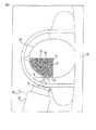
図示されるように、該器械は手術の際に患者の脳33の中の腫瘍32の上に配置される。そして、手術の際には患者の頭蓋に開口部34を設け、カニューレ31を、光ファイバー20がない状態で、該開口部34を経て該腫瘍32の前端部へと位置させる。 As shown, the instrument is placed over a
腫瘍の位置は一般的な外科的、解析的境界決定手法による、MRIの初期実験により、腫瘍の末端部を構成する脳内の閉曲面として決定される。患部の除去すべき部位を正確に決定する外科的解析技術は本発明の構成要素ではないが、当業者においては従来の外科的技術による解析を用いて該閉曲面を決定することができる。 The position of the tumor is determined as a closed curved surface in the brain constituting the terminal portion of the tumor by an initial MRI experiment by a general surgical and analytical boundary determination method. Although a surgical analysis technique for accurately determining a site to be removed from the affected area is not a component of the present invention, those skilled in the art can determine the closed curved surface using analysis by a conventional surgical technique.
カニューレの挿入角度については、当然、主要な血管のような、患者の貫通すべきではない部位を可能な限り避け、また該カニューレが腫瘍の前端部に達した時点で該腫瘍の中心を指すように設定する。 Regarding the angle of insertion of the cannula, it should naturally be avoided as much as possible of sites that should not penetrate the patient, such as main blood vessels, and should point to the center of the tumor when the cannula reaches the front end of the tumor. Set to.
図3の20に示される光ファイバーの構造は、レーザーの位置にある図示しない入口端、及び遠隔端36を有するガラス繊維部分35を含む。該遠隔端36には、ビーム37のレーザーエネルギーを該端36の一側へと偏向する反射器またはプリズムが配設される。これによって、該ビーム37は該光ファイバーの長手方向及び軸方向に対し略直角に偏向される。該ビーム37はテーパ角度が12度から15度の円錐を成形する。このような、光を長手方向に対し直角に偏向する反射器またはプリズムを含む光ファイバーには、既存の商品を利用できる。 The optical fiber structure shown at 20 in FIG. 3 includes a
図中の35で示されるガラス繊維部分は、該光ファイバーを発動機22によって操作可能とするために囲いで覆われている。該光ファイバーの周囲には、末端部39及び延設部40を含む筒体38が成形されている。該末端部39は、該末端部の先端41から距離を置いて該光ファイバーの遠隔端36を覆っている。該末端部の長さは7cmから11cmの範囲内とする。延設部40は長さを48cmから77cmの範囲内とし、前端41から後端42へと延設する。前部39はガラス等の硬質な素材で成形する。延設後部40は光ファイバーの端部36を腫瘍内に移動させるために力を加えることが可能なように、繊維強化プラスティックのような、ガラス程に脆くなく、曲げやねじれに対し剛性を維持できる硬質な素材で成形する。 A glass fiber portion indicated by 35 in the figure is covered with an enclosure so that the optical fiber can be operated by the
該末端部及び該延設部は結合して一体構造として該カニューレ内に滑合することが可能であるように、その直径は共通とする。該前部は、腫瘍の前部すなわち最も近い側の端部に位置するカニューレ端部から、該腫瘍の後端部まで延伸できる長さとする。平均的な腫瘍の大きさは直径が0.5cmから5.0cmの範囲であるので、前述の該前部の長さは該前部の1.25cmを該カニューレ端部に残した状態で該腫瘍の直径の分だけ延伸可能に構成している。このようにして該前部は、光ファイバーがカニューレ内で曲がったり、ねじれたりすることなく、該光ファイバーの向きが該カニューレの軸方向に略一致するようにしている。カニューレへの挿入の際に、曲げ負荷に対して延設部が割れる、あるいは砕ける危険性を回避するために、該延設部の材質にはガラスを用いない。人手によるカニューレへの挿入の際の曲げ負荷に適応でき、また後述する前後動及び回動の際に加わる力に耐えられるような、より脆くない素材が選ばれる。 The distal end and the extension are common in diameter so that they can be joined and slid into the cannula as a unitary structure. The front is of a length that can extend from the end of the cannula located at the front, ie, the nearest end of the tumor, to the rear end of the tumor. Since the average tumor size ranges from 0.5 cm to 5.0 cm in diameter, the anterior length is 1.25 cm of the anterior portion, leaving the cannula end. It is configured to be stretchable by the diameter of the tumor. In this way, the front portion allows the orientation of the optical fiber to substantially match the axial direction of the cannula without the optical fiber being bent or twisted within the cannula. Glass is not used as the material of the extension part in order to avoid the risk of the extension part breaking or breaking with respect to the bending load during insertion into the cannula. A less brittle material is selected that is adaptable to bending loads during manual insertion into the cannula and that can withstand the forces applied during forward and backward movement and rotation described below.
筒状部38には多角形状もしくは非円形部分44、及び末端閉止部分45が取り付けられる。該駆動部材44・45は該延設部に駆動を伝達するために取り付けられる。多角形状部分44は、該延設部及び光ファイバー全体を該光ファイバーの長手方向の軸芯を中心に回動させるための駆動部に連動するように構成される。末端閉止部分45は、該延設部及び光ファイバーを、該長手方向軸芯に沿って前後動させるための前後方向駆動装置に連動するように構成される。このようにして、前記先端36は、カニューレの外端から外側へ突出して腫瘍へと突入したばかりの初期位置から、該腫瘍の最も遠い端部に達するまで移動できるように構成される。さらに、該先端は、光ファイバーの軸芯を中心とする任意の角度で熱エネルギーを加えることを可能とするために、該軸芯を中心に回動可能に構成される。該端部の選択的な前後動及び回動の制御により、カニューレの端から端までその軸芯に沿って伸びる円筒状の領域の全体にわたって熱エネルギーを加えることが可能になる。さらに、任意の前後方向の位置及び角度における加える熱エネルギーの量の制御により、カニューレの軸芯からの所望の深度に達するまで熱エネルギーを加えることが可能となり、あらかじめ腫瘍の境界面を画定するものとして決定された閉曲面内の領域に該腫瘍の領域を一致させることで、選択した領域にわたって患部に加熱効果を付与することが可能となるものである。 A polygonal or
図4に示すように、断面視非円形の駆動部材44は高さが横幅よりも大きい長方形状に構成している。しかし、断面形状が該駆動部分の全域にわたって一定であり、かつ、周囲の駆動部からの動力を受けて連動することが可能なものであれば、他の非円形の断面形状に構成することも可能である。末端閉止部分45は円筒状とし、光ファイバーの駆動発動機への取り付けを容易とするために、上端片45Aを着脱可能に構成している。 As shown in FIG. 4, the
以下において、図5及び図6により、光ファイバーにおいて、駆動部材44・45を介して筒体38に動力を伝達し、先端36を前後動及び回動させるための駆動発動機22について、より詳細に説明する。 In the following, referring to FIG. 5 and FIG. 6, in the optical fiber, the driving
該駆動発動機は上半部51及び下半部52からなるハウジング50を有する。該上半部51及び下半部52は半円筒状で二つを合わせるように構成され、該ハウジングの中心軸線上に沿って延設される光ファイバーに取り付けられる駆動要素を覆っている。該ハウジングの前部53には孔54を有するボスが設けられ、筒体38を滑合させることが可能に構成されている。これは該ハウジング前端において該筒体の動きを誘導するものである。 The drive motor has a
該ハウジング内には第一環状取付部55が設けられ、また該取付部の後方に間隔をあけて第二環状取付部56が設けられる。該第一環状取付部と前部のボスとの間には第一変換器57が、該第二環状取付部の後方には第二変換器58がそれぞれ設けられる。 A first
第一環状取付部55にはベアリング60を介して回動可能な第一駆動円盤59が取り付けられる。第二環状取付部56にはベアリング62を介して第二駆動円盤61が取り付けられる。これらの駆動円盤は同一の形状で、それぞれ、略平面状の円盤部と、該円盤部後方に配され、該円盤部と同一の中心軸を有する円筒部63とからなる。該ベアリングは該環状取付部55・56の円筒状の内壁と、該円筒部63・63の外壁の間に取り付けられる。したがって、該円盤部はそれぞれ、ハウジングの中心軸上における光ファイバーの軸芯を中心に回動可能に取り付けられるものである。 A
該円盤59は、その円盤部の中心の孔を塞ぎ、円筒部63内へと突出する中心栓部64を有する。該栓部は、駆動部材44を覆う、該駆動部材44と同一の断面形状を有する駆動面66と、面取りあるいは円錐状の切り欠きがなされ、該孔へと収斂する引込切欠部65を有する。そして、筒体38の先端部41がハウジングの中心軸に沿って円錐状の該引込切欠部65から挿入され、駆動面もしくは孔66に挿入されて、駆動部材44が該面に接するようにされる。この配置により、円盤59の回動によって筒体38が回動され、それによって光ファイバーが回動される。該駆動部材44の断面形状は均一に構成されるので、該駆動面66内を前後に滑動できる。 The
該円盤61は、該円盤の中心の孔に嵌入される栓部67を有する。該栓部67は、螺子部69に対応する雌螺子山を設けた内壁面68を有する。該螺子部69には、該筒体38のまわりに孔70が設けられ、該筒体38が該孔70に対し回動かつ移動自在となっている。また、該螺子部69は該円盤61の円筒部63を貫通している。該円盤61の回動により該螺子部はハウジングの中心軸,及び筒体38の中心軸方向に対し前後動される。該螺子部の後端部71には、締結部材72が取り付けられている。該締結部材72は、該螺子部の後端部71に取り付けられる固定部73と、該固定部に締結可能な開放部74を有し、末端閉止部分45を該締結部材内において締結するものである。該開放部74は、螺子75・75によって締結される。該末端閉止部分45の上端片45Aは該固定部73中の受け部76に固定され、該螺子部に対し、筒体38の方向を定めている。 The disc 61 has a plug portion 67 that is fitted into a hole in the center of the disc. The plug portion 67 has an inner wall surface 68 provided with a female screw thread corresponding to the
該円盤59・61はそれぞれ駆動モーター77・77・78・78により断続的に駆動される。本実施例においては、該駆動モーターとして、圧電性結晶の振動により往復運動を行う圧電性駆動要素を用い、該円盤それぞれを断続的に角回動させている。 The
二つの該モーター77・77は円盤59を、二つの該モーター78・78は円盤61をそれぞれ駆動する。該モーターはそれぞれハウジングに取り付けられた装着ブラケット77A・78Aに保持される。 The two
末端締結部72は断面視長方形状で、対応する長方形状の断面形状を有するハウジング内の管部72Aに滑合される。したがって、螺子部69は回動に対して固定され、円盤61の回動により、その回動軸に沿って前後動され、光ファイバーは該螺子部に対して自由に回動できる。 The
図示しないその他の構成として、遮蔽室11外の装置制御器25によって駆動される前後動可能なケーブルにより断続動作をさせることが可能である。さらに別の構成として、該モーターの代わりに液圧式あるいは気圧式の原動機を用い、該原動機の往復運動により断続動作を行うことも可能である。 As another configuration (not shown), it is possible to perform an intermittent operation using a cable that can be moved back and forth and driven by the device controller 25 outside the shielding chamber 11. As another configuration, a hydraulic or pneumatic prime mover can be used instead of the motor, and the intermittent operation can be performed by the reciprocating motion of the prime mover.
このように、該円盤それぞれの選択的な回動は、それぞれに発動機によって適切な原動力を供給することで可能となる。 In this way, the selective rotation of each of the disks can be achieved by supplying an appropriate driving force to each of the disks by the motor.
変換器57・58は、円盤、特には該変換器内に突出している該円盤の筒状部63の瞬間的な位置を検出する。該筒状部は、該変換器が個々の円盤の角度を検出するための要素として機能する。このようにして、円盤の位置は、装置制御器25により正確に制御され、円盤59の動作により光ファイバーの角度が、円盤61の動作により光ファイバーの前後方向の位置がそれぞれ制御される。前後方向の位置は螺子部の前後動による末端閉止部分45の前後動によって変化する。光ファイバーが前後方向に対し静止した状態で回動可能とするために、これらの動作は独立して行える構成としている。 The
磁石及びMRI装置の使用中に発動機によって光ファイバーを移動させるために、該発動機及び遮蔽室11内に配置されるその制御装置はMRI装置と併用可能とすることが必要である。そのため、動力供給・制御ケーブル24及び該発動機は、磁界の影響を受けうる強磁性の構成要素を用いずに構成しなければならない。さらに、該発動機22及び該ケーブル24は、MRI解析を行う際に必ず生じる小さな高周波信号の干渉から、適切に遮蔽されている必要がある。 In order to move the optical fiber by the mover during use of the magnet and the MRI apparatus, it is necessary that the mover and its control device arranged in the shielding chamber 11 can be used together with the MRI apparatus. Therefore, the power supply /
したがって、図7に示すように、該遮蔽室11は、該室内の領域への磁石による高周波の干渉を遮断するために導体で覆われている。さらに、該発動機22及び該ケーブル24は、囲いの壁83内のケーブルポート82を介して壁11の開口部81を抜けるよう延設された導体80で覆われ、該遮蔽室の導体と連結された該導体80によって、該発動機22及び該ケーブル24はその全体が囲まれた構成となっている。したがって、該導体80は遮蔽内で「虫食い穴」として機能し、該発動機22及び該ケーブル24は該遮蔽室周辺において遮蔽の外部から保護されている。圧電性結晶の使用はMRI装置との併用において特に適切であるが、前述のその他の駆動装置を用いることも可能である。 Therefore, as shown in FIG. 7, the shielding chamber 11 is covered with a conductor in order to block high-frequency interference from the magnet to the region in the chamber. Further, the
手術の手順において、患者は患者支持台上に位置し、患者の頭部が磁石の位置から動かないように拘束される。その後、MRI装置により除去すべき部位、一般には腫瘍の映像を従来の手法により生成する。その後手術者単独で、あるいは利用可能な適切なソフトウェアを用いて、生成された画像を解析し、図8の90に示される、該腫瘍の領域周りの、該腫瘍の外周面を画定する領域を定める。また、介在する他の組織の損傷を避け、形状において不整でありうる腫瘍の中心を通すために、カニューレを腫瘍へと挿入する最良の経路を決定する。 In the surgical procedure, the patient is positioned on the patient support and is restrained so that the patient's head does not move from the position of the magnet. Thereafter, a site to be removed by the MRI apparatus, generally an image of a tumor, is generated by a conventional method. The generated image is then analyzed by the surgeon alone or using the appropriate software available to determine the area surrounding the tumor area, as shown at 90 in FIG. Determine. It also determines the best path to insert the cannula into the tumor to avoid damage to other intervening tissues and to pass through the center of the tumor, which may be irregular in shape.
カニューレの経路と向きを決定した後に、前述のように開口部34を設け、該カニューレを挿入する。 After determining the path and orientation of the cannula, an
カニューレを定位置において、発動機をフレームに固定し、該発動機の位置を調節することで、光ファイバーを該カニューレの長手方向に沿って挿入可能にする。発動機をカニューレの中心軸に沿って適切に配置し、光ファイバーを該発動機の孔に通してカニューレへと挿入し、その先端のみが該カニューレの外端から外に出るようにする。カニューレから発動機までの距離を調節できるので、螺子部が完全に巻き込まれ、また末端閉止部分が締結部72に位置した時点で、該先端が該カニューレの端部に位置するようにすればよい。 With the cannula in place, the mover is secured to the frame and the position of the mover is adjusted to allow insertion of the optical fiber along the length of the cannula. With the mover properly positioned along the central axis of the cannula, an optical fiber is inserted through the hole in the mover into the cannula so that only its tip exits from the outer end of the cannula. Since the distance from the cannula to the mover can be adjusted, when the screw part is completely wound and the end closing part is located at the
このように発動機と光ファイバーが配置された後に、MRI装置により境界領域90での温度の測定を行う。温度測定は、単に複数の別々の位置で行うのではなく、境界の面全体において行う。温度の測定中に、光ファイバーは手術の開始のために腫瘍内の最初の位置へと前後動される。ビームの角度を選択して、放射線のパルスがレーザーにより放射され、該ビーム37を介して腫瘍へと伝達される。パルスは境界層90における温度が測定されるまで継続される。パルスによって腫瘍へ熱エネルギーが供給されることで、腫瘍は決められた領域において局所的に加熱されるが、該腫瘍自体の特性に応じた割合で腫瘍のその他の部分も加熱される。したがって、ビームによって決められた領域への加熱は、境界層90の温度が事前に決められた55℃から65℃の範囲内の凝結温度に達するまで継続される。一旦該境界層がこの温度に達すれば、この領域の加熱は中止され、光ファイバーは回動と前後動のいずれか、もしくはその両方によって、腫瘍の次の加熱すべき領域へと移動される。境界における温度測定が加熱と同時に、加熱の行き過ぎを防ぐのに充分な早さで行われるので、要求されるパルスの値をあらかじめ予測しておくことは必要ではない。しかし、熱エネルギーを付与する条件によっては、この予測をできるだけ素早く行うことは可能である。 After the motor and the optical fiber are thus arranged, the temperature in the boundary region 90 is measured by the MRI apparatus. The temperature measurement is not performed at a plurality of separate positions, but at the entire boundary surface. During temperature measurement, the optical fiber is moved back and forth to the initial position within the tumor for the start of surgery. With the beam angle selected, a pulse of radiation is emitted by the laser and transmitted to the tumor via the
手術時間の短縮のために、加熱は可能な限り短時間で行うことが望まれる。そのため前述の、初期の解析によって検出される腫瘍の性質に基づいた予測によって、毎秒のパルス数を変化させてもよい。しかし、温度の急激な上昇は境界における温度の行き過ぎを起こし、該境界外部の組織に損傷を与える可能性があるので、加熱速度を大幅に上げることはできない。したがって加熱速度は、腫瘍の大きさと密度に依存して、境界において加熱の行き過ぎの可能性を排除しつつ必要な温度を得るための抑制された範囲内で選択される。また、加熱速度は光ファイバーの軸芯から境界までの距離にも依存する。光ファイバーの軸芯は図8において91で示される。92で示される、腫瘍への光ファイバーの挿入位置における境界までのビームの距離は比較的短く、93で示されるように該距離は腫瘍の中心へと向かうにつれて長くなる。 In order to shorten the operation time, it is desirable to perform heating in as short a time as possible. Therefore, the number of pulses per second may be changed by the above-described prediction based on the nature of the tumor detected by the initial analysis. However, the rapid increase in temperature causes a temperature overshoot at the boundary, which can damage tissue outside the boundary, so the heating rate cannot be increased significantly. Thus, the heating rate depends on the size and density of the tumor and is selected within a constrained range to obtain the required temperature while eliminating the possibility of overheating at the boundary. The heating rate also depends on the distance from the optical fiber core to the boundary. The axis of the optical fiber is indicated by 91 in FIG. The distance of the beam to the boundary at the insertion position of the optical fiber into the tumor, indicated at 92, is relatively short and increases as it goes toward the center of the tumor, as indicated at 93.
境界における温度が必要な値に達するまで、光ファイバーを最初に決めた前後方向の位置及び角度で静止させておくことが望まれる場合がある。このような場合、光ファイバーはその後、ビームが加熱を開始する時の角度と略同一の角度に回動され、その角度での加熱が終了するまで回動されない。こうして、加熱が完了するまで、光ファイバーは個々の角度での加熱がなされてから次の角度へと回動される。 It may be desirable to keep the optical fiber stationary at the initially determined anteroposterior position and angle until the temperature at the boundary reaches the required value. In such a case, the optical fiber is then rotated to an angle approximately the same as the angle at which the beam begins to heat, and is not rotated until heating at that angle is complete. Thus, until the heating is completed, the optical fiber is heated at each angle and then rotated to the next angle.
腫瘍において最初の円形域での加熱がなされた後に、光ファイバーは、その位置での腫瘍の直径とビームの角度に応じた距離だけ前後動され、腫瘍の、決められた温度に達しておらずまだ光ファイバーの侵襲していない領域において次の円形状の加熱域を確保する。こうして、光ファイバーは、段階的に前後動するものであり、この際、当初の分析により判定した腫瘍の直径や構造に応じて距離を変更してもよい。しかし、腫瘍への加熱の総量は、腫瘍の境界より内側の温度解析や腫瘍内での温度傾斜の予測を要することなく、境界における温度のみで決定されるのが望ましい。 After the first round of heating in the tumor, the optical fiber is moved back and forth by a distance depending on the tumor diameter and beam angle at that location, and the tumor has not yet reached the set temperature. The next circular heating area is secured in the non-invasive area of the optical fiber. Thus, the optical fiber moves back and forth in stages, and the distance may be changed according to the diameter and structure of the tumor determined by the initial analysis. However, it is desirable that the total amount of heating to the tumor is determined solely by the temperature at the boundary without requiring temperature analysis inside the tumor boundary or prediction of temperature gradients within the tumor.
腫瘍の境界全体が決められた凝結温度に達すれば手術は完了であり、光ファイバーとカニューレを患者から取り除くために器械は取り外される。 The surgery is complete when the entire tumor boundary reaches a determined setting temperature and the instrument is removed to remove the optical fiber and cannula from the patient.
この装置は腫瘍の境界によって定義される表面温度の制御により加熱を直接かつ正確に制御することが可能であり、これにより腫瘍外部の領域を凝結温度以上に加熱する危険を避けつつ腫瘍全体を必要な温度まで加熱することができる。 This device allows direct and accurate control of heating by controlling the surface temperature defined by the tumor boundary, which requires the entire tumor while avoiding the risk of heating areas outside the tumor above the condensation temperature. It can be heated to a certain temperature.
光ファイバーから加える熱の量を最大化して、より大きな腫瘍を処理するために、光ファイバー周辺の組織を素早く冷却することで加熱の行き過ぎを避けることが強く望まれる。凝結温度を超えた加熱は、炭化の原因となり、それ以上の熱伝達を阻害するので、避ける必要がある。したがって、冷却を行わない場合においては、加えられる熱の量は制限される。このような加えうる熱の量の制限は処理できる腫瘍の大きさを制限するが、組織中のエネルギーを消散させることで腫瘍外の部分が凝結温度に達することを防げる。 In order to maximize the amount of heat applied from the optical fiber and treat larger tumors, it is highly desirable to avoid overheating by quickly cooling the tissue surrounding the optical fiber. Heating above the condensation temperature causes carbonization and impedes further heat transfer and must be avoided. Therefore, in the case where cooling is not performed, the amount of heat applied is limited. This limitation of the amount of heat that can be applied limits the size of the tumor that can be processed, but dissipating the energy in the tissue prevents the outside of the tumor from reaching the condensation temperature.
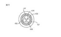
そこで、図9及び図10においては、前述のプローブに代わって使用できる改良型のレーザープローブを示している。該プローブは改良による直径の増大をふまえて、構造の寸法においても若干の改良を要するものである。 9 and 10 show an improved laser probe that can be used in place of the above-described probe. The probe requires a slight improvement in the size of the structure, taking into account the increase in diameter due to the improvement.
改良型のプローブ100は、前述の光分散構造を有する先端部102から前述の光ファイバーの反対側の端部にある光源まで延設される光ファイバー101を含む。また、該プローブは支持管状部材103を有する。該支持管状部材はファイバーを通す多管腔の管としてプラスティックにより成形され、該ファイバーに沿うように該ファイバーの先端部102から前述の該ファイバーの駆動装置にわたって延設され、該管状部材の端部117からは該先端部102が若干突出する構成としている。該管状部材103内には円筒状の管路104が延設され、また該管路に平行に管路105・106が、該管状部材の円筒状の外壁面107の内側に設けられている。 The
該支持管状部材103の端部117の反対側の端部109上に、連結部108が成形され、供給管状部材110・111・112をそれぞれ管路104・105・106と連通している。 On the
このような形式の多管腔の管は市販されていて、また適当な素材によって必要に応じた寸法及び物理特性を有するものとして成形できる。管路104はファイバーの外形に厳密に合う寸法とすることで、該ファイバーを該管路104から管状部材110へと送り込み、該ファイバーの先端部102が支持管状部材の端部117から露出するまで該支持管状部材内に挿入できるようにしている。 Such types of multi-lumen tubes are commercially available and can be molded with suitable dimensions and physical properties as required. The
必要な寸法及び硬度を有する管部材を使用することができるが、多くの場合、該管部材は曲げられ、ねじられる。したがって、支持管状部材の外側には補剛管状部材もしくは筒体114が取り付けられる。該補剛管状部材は、ファイバーの先端部102から離れた端部115から、該先端部102に近接する端部116にわたって延設される。但し、該端部116は、先端部102から後方に間隔をあけて配置される筒状部材103の端部117から、さらに間隔をあけて配置する。該先端部102と該端部116との距離は1インチ未満とする。補剛管状部材114は、MRIへの適合性を有する非強磁性の硬質な素材で成形される。支持管状部材103は補剛管状部材114内に固着することで、該補剛管状部材内で回動したりずれないようにする。補剛管状部材114はMRIの磁界内で用いることのできるチタンやセラミック等の素材で成形する。チタンはMRI映像中に偽信号を生じるので、組織の映像を適切に生成するために補剛管状部材の端部116はファイバーの先端部102からできるだけ離して配置する。 A tube member having the required dimensions and hardness can be used, but in many cases the tube member is bent and twisted. Therefore, a stiffening tubular member or
補剛管状部材114の端部116には、袖部121及び円蓋状もしくは尖頭状の端部122からなるカプセル120が設けられる。該袖部は補剛管状部材の端部116を覆うように固着され、管状部材103の露出部周辺を密閉している。カプセル120は水晶結晶によって透明に構成することで、ファイバーの先端部102から放出される光エネルギーが外に出られるようにしている。該補剛管状部材の端部と該ファイバーの端部との距離は、透明な素材で無理なく成形できる該カプセルの長さに合わせて調整される。 The
管状部材111は冷却液の供給部125に、管状部材112は冷却液の回収部126にそれぞれ接続される。冷却液は管路105を経て管状部材103の端部117からカプセル内に送られ、その後管路106から戻される。該冷却液には低温において窒素ガスに気化できる単なる液体窒素を用いることができ、ガス圧によって管路105から押出され、管路106より戻され、回収部126からそのまま大気中に放出される。 The tubular member 111 is connected to the
その他の構成として、冷却部125と回収部126により冷凍サイクルを構成し、適当な冷媒を圧縮、凝縮させ、カプセル120内の冷却部分において気化させることで、該カプセル120の周囲の組織から熱を冷却部分に移動させるようにすることもできる。 As another configuration, a refrigeration cycle is configured by the
前述の構成においては、管路105・106による気体もしくは液体の冷媒の供給が可能であるとともに、ファイバー101は補剛管状部材114に対して横ずれや回動をしないように保持されるものである。よって、ファイバーの先端部102の位置は補剛管状部材により厳密に制御され、該補剛管状部材は図9において略図的に示される連結器130・131により、前述のような往復運動発動機を用いた構成によって駆動される。 In the above-described configuration, gas or liquid refrigerant can be supplied through the
以上で説明した本発明においては様々な改良が可能であり、また請求範囲の意図及び視野からは多くの異なる実施例をあげることが可能である。よって、本明細書において示されるものはその一例であり、これのみに限定されるものではない。 Various improvements can be made in the present invention described above, and many different embodiments can be given from the intent and scope of the claims. Therefore, what is shown in this specification is the example, and is not limited only to this.
20 光ファイバー
22 発動機
38 筒体
59 第1駆動円盤
61 第2駆動円盤
103 支持管状部材
100 プローブ
31 カニューレDESCRIPTION OF SYMBOLS 20
Claims (10)
Translated fromJapanese入口端と出口端とを備える光ファイバーと、
該光ファイバーに該入口端から光エネルギーを供給するレーザー光源と、
該出口端に配置され、該光ファイバーの長手方向軸芯に対するビーム中の光の角度を制御するものであって、該軸芯を中心に該光ファイバーを回動させることで、該軸芯を中心に該ビームを回動する構成とした光偏向器と、
該光ファイバーから間隔をあけて配置され、該光ファイバーの長手方向に沿った前後動、及び該光ファイバーの軸芯を中心とする回動を行う駆動装置と、
該光ファイバーの出口端付近部に、該出口端付近部を覆うように取り付けられ、該光ファイバーを補強するための筒状部材であり、該駆動装置からの前記前後動及び前記回動の伝達のために該駆動装置に連結され、該光ファイバーが、前記前後動の移動の時に横方向に曲がらないよう、及び前記回動の時にねじれないように、該光ファイバーを保護し、該駆動装置から該光ファイバー端部へ運動を伝達するものとした筒状部材と、を備える器械。An instrument for the treatment of a patient,
An optical fiber comprising an inlet end and an outlet end;
A laser light source for supplying light energy to the optical fiber from the entrance end;
It is arranged at the exit end and controls the angle of light in the beam with respect to the longitudinal axis of the optical fiber, and by rotating the optical fiber around the axis, the axis is centered. An optical deflector configured to rotate the beam;
A driving device that is arranged at a distance from the optical fiber, and that moves back and forth along the longitudinal direction of the optical fiber and rotates around the axis of the optical fiber;
A cylindrical member attached to the vicinity of the exit end of the optical fiber so as to cover the vicinity of the exit end, and for reinforcing the optical fiber, and for transmitting the forward and backward movement and the rotation from the drive device The optical fiber is connected to the drive device and protects the optical fiber from being bent in the lateral direction during the back-and-forth movement and from being twisted during the rotation. And a cylindrical member that transmits motion to the part.
該プローブを駆動するための駆動装置であって、該プローブを該駆動装置により該軸芯を中心に回動可能とすることで、該円状の領域内の異なる角度範囲において加熱を行えるように構成した駆動装置と、
該プローブの端部を冷却することで、熱伝導により該プローブの周囲から熱を除くことを可能とする手段とを備え、
前記熱源は、レーザーと、該レーザーからの光を伝達するための光ファイバーとを有し、該光ファイバーは、一方の端部にて、該光ファイバーに対する所定の方向に該レーザーからの光を向け、前記円状の領域内に前記の限定された角度範囲を形成するための光偏向装置を含み、
前記光ファイバーの出口端付近部には、光ファイバーを補強するための筒状部材が出口端付近部を覆うように取り付けられており、該筒状部材は駆動されることで該光ファイバーを前後動及び回動させるものであり、該光ファイバーが該前後動の時にその移動方向に対し横方向に曲がらないよう、及び該回動の時にねじれないように、該光ファイバーを保護するものであることを特徴とする治療用器械。A heat source for heating the affected part, the heat source being an invasive probe having an axial core in a longitudinal direction, deflecting heat with respect to the axial core, and heating by the probe A probe configured to be made in a central circular region and configured to define a heating range consisting of a limited angular range within the circular region by the direction of heat; ,
A driving device for driving the probe, wherein the probe can be rotated about the axis by the driving device so that heating can be performed in different angular ranges in the circular region. A configured driving device; and
Means for allowing heat to be removed from the periphery of the probe by heat conduction by cooling the end of the probe;
The heat source includes a laser and an optical fiber for transmitting light from the laser, and the optical fiber directs light from the laser in a predetermined direction with respect to the optical fiber at one end, Including an optical deflection device for forming said limited angular range in a circular region,
A cylindrical member for reinforcing the optical fiber is attached to the vicinity of the exit end of the optical fiber so as to cover the vicinity of the exit end, and the cylindrical member is driven to move the optical fiber back and forth and rotate. The optical fiber is protected so that the optical fiber does not bend laterally with respect to the moving direction during the back-and-forth movement and is not twisted during the rotation. Therapeutic instrument.
該区切られた時間での患部における温度変化の間、該患部の外周面上のある位置における温度に反応し、該患部の外周面における温度の測定を、該位置での加熱を停止する時期を定めるための要素として用いるように構成したプローブ制御装置とを有することを特徴とする請求項7または8に記載の器械。During a temperature change in the affected area at a delimited time, a continuous output signal at the time is generated corresponding to the temperature in the affected area, and the output signal is used to generate at least one region in the affected area. A non-invasive detector configured to measure temperature changes in
During the temperature change in the affected area at the divided time, the temperature at a certain position on the outer circumferential surface of the affected area is measured, and the temperature at the outer circumferential surface of the affected area is measured, and the heating at the position is stopped. 9. An instrument according to claim 7 or 8, comprising a probe controller configured to be used as an element for definition.
入口端と出口端とを備える光ファイバーと、
該光ファイバーに該入口端から光エネルギーを供給するレーザー光源と、
該出口端に配置され、該光ファイバーの長手方向軸芯に対するビーム中の光の角度を制御するものであって、該軸芯を中心に該光ファイバーを回動させることで、該軸芯を中心に該ビームを回動する構成とした光偏向器と、
患部に挿入するために硬質で細長く構成されたカニューレであって、該光ファイバーの出口端が該カニューレを抜けて該患部に侵入できるように、カニューレを通って延びる該光ファイバーの出口端近傍部を受け入れる孔を有するカニューレと、
該カニューレに対して、該光ファイバーの長手方向に沿った前後動、及び該光ファイバーの軸芯を中心とする回動を行う駆動装置と、
該光ファイバーの出口端付近部に、該出口端付近部を覆うように取り付けられ、該光ファイバーを補強するための筒状部材であり、前記駆動装置からの前記前後動及び前記回動の伝達のために該駆動装置に連結され、該光ファイバーが、前記前後動の移動の時に横方向に曲がらないよう、及び前記回動の時にねじれないように、該光ファイバーを保護し、該駆動装置から該光ファイバー端部へ運動を伝達するものとした筒状部材と、を備える器械。An instrument for the treatment of a patient,
An optical fiber comprising an inlet end and an outlet end;
A laser light source for supplying light energy to the optical fiber from the entrance end;
It is arranged at the exit end and controls the angle of light in the beam with respect to the longitudinal axis of the optical fiber, and by rotating the optical fiber around the axis, the axis is centered. An optical deflector configured to rotate the beam;
A rigid and elongated cannula for insertion into an affected area, receiving the vicinity of the exit end of the optical fiber extending through the cannula so that the exit end of the optical fiber can pass through the cannula and enter the affected area A cannula having a hole;
A drive device that performs forward / backward movement along the longitudinal direction of the optical fiber and rotation about the axis of the optical fiber with respect to the cannula;
A cylindrical member attached to the vicinity of the exit end of the optical fiber so as to cover the vicinity of the exit end, and for reinforcing the optical fiber, and for transmitting the forward and backward movement and the rotation from the drive device The optical fiber is connected to the drive device and protects the optical fiber from being bent in the lateral direction during the back-and-forth movement and from being twisted during the rotation. And a cylindrical member that transmits motion to the part.
Applications Claiming Priority (2)
| Application Number | Priority Date | Filing Date | Title |
|---|---|---|---|
| US09/593,699US6418337B1 (en) | 2000-06-15 | 2000-06-15 | MRI guided hyperthermia surgery |
| US09/593,699 | 2000-06-15 |
Related Parent Applications (1)
| Application Number | Title | Priority Date | Filing Date |
|---|---|---|---|
| JP2002510007ADivisionJP4417006B2 (en) | 2000-06-15 | 2001-06-15 | MRI induction thermosurgical instrument |
Publications (2)
| Publication Number | Publication Date |
|---|---|
| JP2009297553A JP2009297553A (en) | 2009-12-24 |
| JP5155273B2true JP5155273B2 (en) | 2013-03-06 |
Family
ID=24375772
Family Applications (2)
| Application Number | Title | Priority Date | Filing Date |
|---|---|---|---|
| JP2002510007AExpired - Fee RelatedJP4417006B2 (en) | 2000-06-15 | 2001-06-15 | MRI induction thermosurgical instrument |
| JP2009224862AExpired - Fee RelatedJP5155273B2 (en) | 2000-06-15 | 2009-09-29 | MRI induction thermosurgical instrument |
Family Applications Before (1)
| Application Number | Title | Priority Date | Filing Date |
|---|---|---|---|
| JP2002510007AExpired - Fee RelatedJP4417006B2 (en) | 2000-06-15 | 2001-06-15 | MRI induction thermosurgical instrument |
Country Status (9)
| Country | Link |
|---|---|
| US (2) | US6418337B1 (en) |
| EP (2) | EP1289441B1 (en) |
| JP (2) | JP4417006B2 (en) |
| AT (1) | ATE422850T1 (en) |
| AU (1) | AU2001267231A1 (en) |
| CA (3) | CA2690040C (en) |
| DE (1) | DE60137687D1 (en) |
| ES (1) | ES2322026T3 (en) |
| WO (1) | WO2001095821A2 (en) |
Families Citing this family (78)
| Publication number | Priority date | Publication date | Assignee | Title |
|---|---|---|---|---|
| US7363071B2 (en) | 1999-05-26 | 2008-04-22 | Endocare, Inc. | Computer guided ablation of tissue using integrated ablative/temperature sensing devices |
| US8527046B2 (en) | 2000-04-20 | 2013-09-03 | Medtronic, Inc. | MRI-compatible implantable device |
| US8256430B2 (en) | 2001-06-15 | 2012-09-04 | Monteris Medical, Inc. | Hyperthermia treatment and probe therefor |
| WO2003002243A2 (en) | 2001-06-27 | 2003-01-09 | Remon Medical Technologies Ltd. | Method and device for electrochemical formation of therapeutic species in vivo |
| JP2003116869A (en)* | 2001-10-18 | 2003-04-22 | Honda Seiki Kk | Ultrasonic curing apparatus and ultrasonic diagnostic apparatus |
| JP4142586B2 (en)* | 2001-12-14 | 2008-09-03 | モンテリス メディカル インコーポレイティド | Thermotherapy and probe therefor |
| US20080177268A1 (en)* | 2002-02-14 | 2008-07-24 | Wolfgang Daum | Minimally-Invasive Approach to Bone-Obstructed Soft Tissue |
| US7163655B2 (en)* | 2002-03-28 | 2007-01-16 | Scimed Life Systems, Inc. | Method and apparatus for extruding polymers employing microwave energy |
| US6979420B2 (en)* | 2002-03-28 | 2005-12-27 | Scimed Life Systems, Inc. | Method of molding balloon catheters employing microwave energy |
| CA2477758A1 (en)* | 2002-03-28 | 2003-10-09 | Scimed Life Systems, Inc. | Polymer welding using ferromagnetic particles |
| US7267661B2 (en) | 2002-06-17 | 2007-09-11 | Iradimed Corporation | Non-magnetic medical infusion device |
| US7404809B2 (en) | 2004-10-12 | 2008-07-29 | Iradimed Corporation | Non-magnetic medical infusion device |
| US7553295B2 (en)* | 2002-06-17 | 2009-06-30 | Iradimed Corporation | Liquid infusion apparatus |
| US8862203B2 (en)* | 2003-03-27 | 2014-10-14 | Boston Scientific Scimed Inc. | Medical device with temperature modulator for use in magnetic resonance imaging |
| US20040199151A1 (en)* | 2003-04-03 | 2004-10-07 | Ceramoptec Industries, Inc. | Power regulated medical underskin irradiation treament system |
| US7270656B2 (en) | 2003-11-07 | 2007-09-18 | Visualase, Inc. | Cooled laser fiber for improved thermal therapy |
| US8801701B2 (en)* | 2005-03-09 | 2014-08-12 | Sunnybrook Health Sciences Centre | Method and apparatus for obtaining quantitative temperature measurements in prostate and other tissue undergoing thermal therapy treatment |
| US7771418B2 (en)* | 2005-03-09 | 2010-08-10 | Sunnybrook Health Sciences Centre | Treatment of diseased tissue using controlled ultrasonic heating |
| US7603161B2 (en)* | 2005-12-30 | 2009-10-13 | Medtronic, Inc. | Position detection in a magnetic field |
| US8840660B2 (en) | 2006-01-05 | 2014-09-23 | Boston Scientific Scimed, Inc. | Bioerodible endoprostheses and methods of making the same |
| US8089029B2 (en) | 2006-02-01 | 2012-01-03 | Boston Scientific Scimed, Inc. | Bioabsorbable metal medical device and method of manufacture |
| US7525312B2 (en)* | 2006-03-21 | 2009-04-28 | Fonar Corporation | System for magnetic resonance imaging assisted surgery |
| US8048150B2 (en) | 2006-04-12 | 2011-11-01 | Boston Scientific Scimed, Inc. | Endoprosthesis having a fiber meshwork disposed thereon |
| EP2408052B1 (en)* | 2006-05-12 | 2016-07-13 | Invivo Corporation | Wireless patient parameter sensors for use in MRI |
| WO2008002778A2 (en) | 2006-06-29 | 2008-01-03 | Boston Scientific Limited | Medical devices with selective coating |
| US20100241111A1 (en)* | 2006-07-04 | 2010-09-23 | Bracco Imaging S.P.A. | Device for localized thermal ablation of biological tissues, particularly tumoral tissues or the like |
| JP5001363B2 (en)* | 2006-07-04 | 2012-08-15 | ブラッコ イメージング ソチエタ ペル アチオニ | An ablation device that cauterizes biological tissue such as tumorous tissue locally by heat. |
| EP2054537A2 (en) | 2006-08-02 | 2009-05-06 | Boston Scientific Scimed, Inc. | Endoprosthesis with three-dimensional disintegration control |
| JP2010503489A (en) | 2006-09-15 | 2010-02-04 | ボストン サイエンティフィック リミテッド | Biodegradable endoprosthesis and method for producing the same |
| WO2008034066A1 (en) | 2006-09-15 | 2008-03-20 | Boston Scientific Limited | Bioerodible endoprostheses and methods of making the same |
| WO2008036548A2 (en) | 2006-09-18 | 2008-03-27 | Boston Scientific Limited | Endoprostheses |
| CN101164637B (en)* | 2006-10-16 | 2011-05-18 | 重庆融海超声医学工程研究中心有限公司 | Ultrasonic therapeutic system capable of reducing electromagnetic interference to imaging equipment |
| ES2506144T3 (en) | 2006-12-28 | 2014-10-13 | Boston Scientific Limited | Bioerodible endoprosthesis and their manufacturing procedure |
| US8002823B2 (en) | 2007-07-11 | 2011-08-23 | Boston Scientific Scimed, Inc. | Endoprosthesis coating |
| US7942926B2 (en) | 2007-07-11 | 2011-05-17 | Boston Scientific Scimed, Inc. | Endoprosthesis coating |
| US8105282B2 (en) | 2007-07-13 | 2012-01-31 | Iradimed Corporation | System and method for communication with an infusion device |
| US9403029B2 (en)* | 2007-07-18 | 2016-08-02 | Visualase, Inc. | Systems and methods for thermal therapy |
| US20090048610A1 (en)* | 2007-08-14 | 2009-02-19 | Bme Capital Holdings Ltd. | Medical probe introducer |
| US8052745B2 (en) | 2007-09-13 | 2011-11-08 | Boston Scientific Scimed, Inc. | Endoprosthesis |
| US20090088625A1 (en)* | 2007-10-01 | 2009-04-02 | Kenneth Oosting | Photonic Based Non-Invasive Surgery System That Includes Automated Cell Control and Eradication Via Pre-Calculated Feed-Forward Control Plus Image Feedback Control For Targeted Energy Delivery |
| DE102007054324B4 (en)* | 2007-11-14 | 2009-10-22 | Siemens Ag | Device for radiotherapy under image monitoring |
| US9011508B2 (en)* | 2007-11-30 | 2015-04-21 | Lockheed Martin Corporation | Broad wavelength profile to homogenize the absorption profile in optical stimulation of nerves |
| US9687681B2 (en)* | 2008-01-14 | 2017-06-27 | Koninklijke Philips N.V. | Therapy system with temperature control |
| US20090222059A1 (en)* | 2008-02-28 | 2009-09-03 | Searete Llc, A Limited Liability Corporation Of The State Of Delaware | Shaped implantation device |
| WO2009108933A2 (en)* | 2008-02-28 | 2009-09-03 | Palomar Medical Technologies, Inc. | Systems and methods for treatment of soft tissue |
| US8236046B2 (en) | 2008-06-10 | 2012-08-07 | Boston Scientific Scimed, Inc. | Bioerodible endoprosthesis |
| EP2143442A1 (en) | 2008-07-11 | 2010-01-13 | Peter Jon Nelson | Treatment of solid tumors with tissue inhibitors of metalloproteinases(TIMPs) |
| US8728092B2 (en) | 2008-08-14 | 2014-05-20 | Monteris Medical Corporation | Stereotactic drive system |
| US8747418B2 (en) | 2008-08-15 | 2014-06-10 | Monteris Medical Corporation | Trajectory guide |
| US8382824B2 (en) | 2008-10-03 | 2013-02-26 | Boston Scientific Scimed, Inc. | Medical implant having NANO-crystal grains with barrier layers of metal nitrides or fluorides |
| US9192778B2 (en)* | 2009-01-30 | 2015-11-24 | Medizinische Hochschule Hannover | Cochlea stimulator |
| EP2403546A2 (en) | 2009-03-02 | 2012-01-11 | Boston Scientific Scimed, Inc. | Self-buffering medical implants |
| TWI433822B (en) | 2009-12-28 | 2014-04-11 | Asahi Glass Co Ltd | A method of manufacturing a display device |
| ES2714390T3 (en) | 2010-03-09 | 2019-05-28 | Profound Medical Inc | Ulttrasound therapy applicator |
| US11027154B2 (en) | 2010-03-09 | 2021-06-08 | Profound Medical Inc. | Ultrasonic therapy applicator and method of determining position of ultrasonic transducers |
| WO2011112251A1 (en) | 2010-03-09 | 2011-09-15 | Profound Medical Inc. | Fluid circuits for temperature control in a thermal therapy system |
| US9707413B2 (en) | 2010-03-09 | 2017-07-18 | Profound Medical Inc. | Controllable rotating ultrasound therapy applicator |
| WO2011115664A2 (en)* | 2010-03-14 | 2011-09-22 | Profound Medical Inc. | Mri-compatible motor and positioning system |
| US9017319B2 (en)* | 2011-01-05 | 2015-04-28 | Covidien Lp | Energy-delivery devices with flexible fluid-cooled shaft, inflow/outflow junctions suitable for use with same, and systems including same |
| US9011421B2 (en)* | 2011-01-05 | 2015-04-21 | Covidien Lp | Energy-delivery devices with flexible fluid-cooled shaft, inflow/outflow junctions suitable for use with same, and systems including same |
| US8974478B2 (en) | 2011-09-20 | 2015-03-10 | Covidien Lp | Ultrasonic surgical system having a fluid cooled blade and related cooling methods therefor |
| JP6392667B2 (en) | 2011-12-27 | 2018-09-19 | コーニンクレッカ フィリップス エヌ ヴェKoninklijke Philips N.V. | Magnetic resonance thermography: High resolution imaging of thermal anomalies |
| WO2013131577A1 (en)* | 2012-03-09 | 2013-09-12 | Charité - Universitätsmedizin Berlin | Applicator for medical thermotherapy |
| EP2866723A4 (en) | 2012-06-27 | 2016-12-14 | Monteris Medical Corp | GUIDED THERAPY BY IMAGE OF A FABRIC |
| US10675113B2 (en) | 2014-03-18 | 2020-06-09 | Monteris Medical Corporation | Automated therapy of a three-dimensional tissue region |
| US20150265353A1 (en) | 2014-03-18 | 2015-09-24 | Monteris Medical Corporation | Image-guided therapy of a tissue |
| US9433383B2 (en) | 2014-03-18 | 2016-09-06 | Monteris Medical Corporation | Image-guided therapy of a tissue |
| US10327830B2 (en) | 2015-04-01 | 2019-06-25 | Monteris Medical Corporation | Cryotherapy, thermal therapy, temperature modulation therapy, and probe apparatus therefor |
| US11172821B2 (en) | 2016-04-28 | 2021-11-16 | Medtronic Navigation, Inc. | Navigation and local thermometry |
| EP3335660B1 (en)* | 2016-12-14 | 2021-01-20 | Clinical Laserthermia Systems AB | Apparatus for controlling laser thermotherapy |
| US11268506B2 (en) | 2017-12-22 | 2022-03-08 | Iradimed Corporation | Fluid pumps for use in MRI environment |
| CN108836477B (en)* | 2018-05-14 | 2021-05-11 | 华科精准(北京)医疗科技有限公司 | Laser hyperthermia device and system based on magnetic resonance guidance |
| ES2925367T3 (en)* | 2020-05-04 | 2022-10-17 | Synergia Medical | Active implantable stimulation device for stimulation of a vagus nerve on demand |
| CN117860399A (en)* | 2020-12-31 | 2024-04-12 | 华科精准(北京)医疗科技有限公司 | Device for controlling rotation of elongated member |
| CN114681069B (en)* | 2020-12-31 | 2023-11-14 | 华科精准(北京)医疗科技有限公司 | Stereotactic transmission system for controlling elongated members |
| CN114681053B (en)* | 2020-12-31 | 2023-07-04 | 华科精准(北京)医疗科技有限公司 | Magnetic resonance guided laser ablation treatment system |
| US12102489B2 (en) | 2021-06-30 | 2024-10-01 | Clearpoint Neuro, Inc. | Image-guided surgical systems with quantitative evaluation of in vivo thermal treatments and related methods |
| CN114110114B (en)* | 2021-12-24 | 2023-12-01 | 杭州佳量医疗科技有限公司 | An optical fiber catheter unidirectional stepping device and driving system |
Family Cites Families (37)
| Publication number | Priority date | Publication date | Assignee | Title |
|---|---|---|---|---|
| US4111209A (en)* | 1977-04-18 | 1978-09-05 | Datascope Corporation | Topical hypothermia apparatus and method for treating the human body and the like |
| US5370675A (en)* | 1992-08-12 | 1994-12-06 | Vidamed, Inc. | Medical probe device and method |
| US4671254A (en) | 1985-03-01 | 1987-06-09 | Memorial Hospital For Cancer And Allied Diseases | Non-surgical method for suppression of tumor growth |
| US4914608A (en) | 1988-08-19 | 1990-04-03 | The United States Of America As Represented By The Department Of Health And Human Services | In-vivo method for determining and imaging temperature of an object/subject from diffusion coefficients obtained by nuclear magnetic resonance |
| US5284144A (en)* | 1989-11-22 | 1994-02-08 | The United States Of America As Represented By The Secretary Of The Dept. Of Health & Human Services | Apparatus for hyperthermia treatment of cancer |
| US5370649A (en) | 1991-08-16 | 1994-12-06 | Myriadlase, Inc. | Laterally reflecting tip for laser transmitting fiber |
| US5291890A (en) | 1991-08-29 | 1994-03-08 | General Electric Company | Magnetic resonance surgery using heat waves produced with focussed ultrasound |
| WO1993016641A1 (en)* | 1992-02-21 | 1993-09-02 | Diasonics, Inc. | Ultrasound intracavity system for imaging therapy planning and treatment of focal disease |
| US5247935A (en)* | 1992-03-19 | 1993-09-28 | General Electric Company | Magnetic resonance guided focussed ultrasound surgery |
| US5620479A (en)* | 1992-11-13 | 1997-04-15 | The Regents Of The University Of California | Method and apparatus for thermal therapy of tumors |
| EP0610991A3 (en)* | 1993-02-08 | 1995-04-19 | Xintec Corp | Device for laser assisted transurethral resection of the prostate(TURP). |
| US5366456A (en) | 1993-02-08 | 1994-11-22 | Xintec Corporation | Angle firing fiber optic laser scalpel and method of use |
| JP3860227B2 (en) | 1993-03-10 | 2006-12-20 | 株式会社東芝 | Ultrasonic therapy device used under MRI guide |
| US5307812A (en)* | 1993-03-26 | 1994-05-03 | General Electric Company | Heat surgery system monitored by real-time magnetic resonance profiling |
| US5454807A (en) | 1993-05-14 | 1995-10-03 | Boston Scientific Corporation | Medical treatment of deeply seated tissue using optical radiation |
| US5320617A (en) | 1993-06-25 | 1994-06-14 | Leach Gary E | Method of laser-assisted prostatectomy and apparatus for carrying out the method |
| US5368031A (en)* | 1993-08-29 | 1994-11-29 | General Electric Company | Magnetic resonance surgery using heat waves produced with a laser fiber |
| US5492122A (en)* | 1994-04-15 | 1996-02-20 | Northrop Grumman Corporation | Magnetic resonance guided hyperthermia |
| US5733277A (en) | 1994-06-22 | 1998-03-31 | Pallarito; Allan L. | Optical fibre and laser for removal of arterial or vascular obstructions |
| US5537499A (en) | 1994-08-18 | 1996-07-16 | Laser Peripherals, Inc. | Side-firing laser optical fiber probe and method of making same |
| US5620438A (en)* | 1995-04-20 | 1997-04-15 | Angiomedics Ii Incorporated | Method and apparatus for treating vascular tissue following angioplasty to minimize restenosis |
| US5823941A (en) | 1995-10-23 | 1998-10-20 | Shaunnessey; Jerome | Apparatus for directing the movement of an endoscopic surgical laser especially for use in vaporizing brain tumors |
| GB9521784D0 (en)* | 1995-10-24 | 1996-01-03 | Rosslyn Medical Ltd | Diagnostic apparatus |
| US5825958A (en)* | 1996-01-25 | 1998-10-20 | Pharos Optics, Inc. | Fiber optic delivery system for infrared lasers |
| US5807383A (en)* | 1996-05-13 | 1998-09-15 | United States Surgical Corporation | Lasing device |
| US5785704A (en) | 1996-07-29 | 1998-07-28 | Mrc Systems Gmbh | Method for performing stereotactic laser surgery |
| US5827313A (en)* | 1996-09-27 | 1998-10-27 | Boston Scientific Corporation | Device for controlled longitudinal movement of an operative element within a catheter sheath and method |
| US6293282B1 (en)* | 1996-11-05 | 2001-09-25 | Jerome Lemelson | System and method for treating select tissue in living being |
| US5872879A (en)* | 1996-11-25 | 1999-02-16 | Boston Scientific Corporation | Rotatable connecting optical fibers |
| WO1998052465A1 (en) | 1997-05-23 | 1998-11-26 | Transurgical, Inc. | Mri-guided therapeutic unit and methods |
| US6086532A (en)* | 1997-09-26 | 2000-07-11 | Ep Technologies, Inc. | Systems for recording use of structures deployed in association with heart tissue |
| DE19816917A1 (en)* | 1998-04-16 | 1999-10-28 | Siemens Ag | Process for spatially resolved temperature monitoring, suspension of ferromagnetic microparticles and use of this suspension |
| US6425867B1 (en)* | 1998-09-18 | 2002-07-30 | University Of Washington | Noise-free real time ultrasonic imaging of a treatment site undergoing high intensity focused ultrasound therapy |
| US6298259B1 (en)* | 1998-10-16 | 2001-10-02 | Univ Minnesota | Combined magnetic resonance imaging and magnetic stereotaxis surgical apparatus and processes |
| US6246896B1 (en)* | 1998-11-24 | 2001-06-12 | General Electric Company | MRI guided ablation system |
| US6332891B1 (en)* | 1999-02-16 | 2001-12-25 | Stryker Corporation | System and method for performing image guided surgery |
| US6551274B2 (en)* | 2000-02-29 | 2003-04-22 | Biosense Webster, Inc. | Cryoablation catheter with an expandable cooling chamber |
- 2000
- 2000-06-15USUS09/593,699patent/US6418337B1/ennot_activeExpired - Lifetime
- 2001
- 2001-06-15CACA2690040Apatent/CA2690040C/ennot_activeExpired - Lifetime
- 2001-06-15CACA2757358Apatent/CA2757358A1/ennot_activeAbandoned
- 2001-06-15CACA2408811Apatent/CA2408811C/ennot_activeExpired - Lifetime
- 2001-06-15ESES01944836Tpatent/ES2322026T3/ennot_activeExpired - Lifetime
- 2001-06-15WOPCT/CA2001/000905patent/WO2001095821A2/enactiveApplication Filing
- 2001-06-15EPEP01944836Apatent/EP1289441B1/ennot_activeExpired - Lifetime
- 2001-06-15ATAT01944836Tpatent/ATE422850T1/ennot_activeIP Right Cessation
- 2001-06-15DEDE60137687Tpatent/DE60137687D1/ennot_activeExpired - Lifetime
- 2001-06-15EPEP09152951.1Apatent/EP2055232B1/ennot_activeExpired - Lifetime
- 2001-06-15AUAU2001267231Apatent/AU2001267231A1/ennot_activeAbandoned
- 2001-06-15JPJP2002510007Apatent/JP4417006B2/ennot_activeExpired - Fee Related
- 2001-12-14USUS10/014,846patent/US7167741B2/ennot_activeExpired - Lifetime
- 2009
- 2009-09-29JPJP2009224862Apatent/JP5155273B2/ennot_activeExpired - Fee Related
Also Published As
| Publication number | Publication date |
|---|---|
| CA2408811C (en) | 2010-08-03 |
| EP1289441B1 (en) | 2009-02-18 |
| US7167741B2 (en) | 2007-01-23 |
| CA2408811A1 (en) | 2001-12-20 |
| DE60137687D1 (en) | 2009-04-02 |
| ES2322026T3 (en) | 2009-06-16 |
| CA2690040C (en) | 2012-01-17 |
| JP4417006B2 (en) | 2010-02-17 |
| EP2055232A3 (en) | 2009-08-05 |
| EP2055232A2 (en) | 2009-05-06 |
| HK1126379A1 (en) | 2009-09-04 |
| JP2009297553A (en) | 2009-12-24 |
| EP1289441A2 (en) | 2003-03-12 |
| US20020193682A1 (en) | 2002-12-19 |
| CA2757358A1 (en) | 2001-12-20 |
| EP2055232B1 (en) | 2016-02-17 |
| ATE422850T1 (en) | 2009-03-15 |
| WO2001095821A2 (en) | 2001-12-20 |
| AU2001267231A1 (en) | 2001-12-24 |
| WO2001095821A3 (en) | 2002-05-16 |
| JP2004502517A (en) | 2004-01-29 |
| CA2690040A1 (en) | 2001-12-20 |
| US6418337B1 (en) | 2002-07-09 |
Similar Documents
| Publication | Publication Date | Title |
|---|---|---|
| JP5155273B2 (en) | MRI induction thermosurgical instrument | |
| JP4142586B2 (en) | Thermotherapy and probe therefor | |
| US9333038B2 (en) | Hyperthermia treatment and probe therefore | |
| JP4338976B2 (en) | Apparatus and method for supplying ablative laser energy and determining the volume of a destroyed tumor mass | |
| CN113573646B (en) | Needle guide for oblique intracavitary transducer | |
| TWI414330B (en) | A guided positioning module and a treatment system having the positioning module | |
| US20090118724A1 (en) | Method and Apparatus for Positioning a Medical Instrument | |
| EP3277164A1 (en) | Cryotherapy, thermal therapy, temperature modulation therapy, and probe apparatus therefor | |
| JP2011502686A (en) | Method and apparatus for position tracking of therapeutic ultrasound transducers | |
| JP2012519048A (en) | Transurethral ultrasound probe for prostate treatment | |
| KR20060020656A (en) | Ultrasound Probe with Center Opening | |
| US10751123B2 (en) | Thermoablation probe | |
| WO1997029700A1 (en) | Multi-element energy focusing | |
| HK1126379B (en) | Mri guided hyperthermia surgery |
Legal Events
| Date | Code | Title | Description |
|---|---|---|---|
| A621 | Written request for application examination | Free format text:JAPANESE INTERMEDIATE CODE: A621 Effective date:20091027 | |
| A131 | Notification of reasons for refusal | Free format text:JAPANESE INTERMEDIATE CODE: A131 Effective date:20111129 | |
| A521 | Request for written amendment filed | Free format text:JAPANESE INTERMEDIATE CODE: A523 Effective date:20120229 | |
| A02 | Decision of refusal | Free format text:JAPANESE INTERMEDIATE CODE: A02 Effective date:20120327 | |
| A521 | Request for written amendment filed | Free format text:JAPANESE INTERMEDIATE CODE: A523 Effective date:20120727 | |
| A911 | Transfer to examiner for re-examination before appeal (zenchi) | Free format text:JAPANESE INTERMEDIATE CODE: A911 Effective date:20120907 | |
| TRDD | Decision of grant or rejection written | ||
| A01 | Written decision to grant a patent or to grant a registration (utility model) | Free format text:JAPANESE INTERMEDIATE CODE: A01 Effective date:20121106 | |
| A61 | First payment of annual fees (during grant procedure) | Free format text:JAPANESE INTERMEDIATE CODE: A61 Effective date:20121206 | |
| FPAY | Renewal fee payment (event date is renewal date of database) | Free format text:PAYMENT UNTIL: 20151214 Year of fee payment:3 | |
| R150 | Certificate of patent or registration of utility model | Free format text:JAPANESE INTERMEDIATE CODE: R150 | |
| S111 | Request for change of ownership or part of ownership | Free format text:JAPANESE INTERMEDIATE CODE: R313113 | |
| S531 | Written request for registration of change of domicile | Free format text:JAPANESE INTERMEDIATE CODE: R313531 | |
| R350 | Written notification of registration of transfer | Free format text:JAPANESE INTERMEDIATE CODE: R350 | |
| R250 | Receipt of annual fees | Free format text:JAPANESE INTERMEDIATE CODE: R250 | |
| LAPS | Cancellation because of no payment of annual fees |