JP5153892B2 - Wireless tissue electrical stimulation - Google Patents
Wireless tissue electrical stimulationDownload PDFInfo
- Publication number
- JP5153892B2 JP5153892B2JP2010545866AJP2010545866AJP5153892B2JP 5153892 B2JP5153892 B2JP 5153892B2JP 2010545866 AJP2010545866 AJP 2010545866AJP 2010545866 AJP2010545866 AJP 2010545866AJP 5153892 B2JP5153892 B2JP 5153892B2
- Authority
- JP
- Japan
- Prior art keywords
- electrical stimulation
- tissue
- wireless
- inductive
- coupled
- Prior art date
- Legal status (The legal status is an assumption and is not a legal conclusion. Google has not performed a legal analysis and makes no representation as to the accuracy of the status listed.)
- Expired - Fee Related
Links
- 230000000638stimulationEffects0.000titleclaimsdescription267
- 230000001939inductive effectEffects0.000claimsdescription138
- 210000001519tissueAnatomy0.000claimsdescription130
- 230000005291magnetic effectEffects0.000claimsdescription62
- 230000004907fluxEffects0.000claimsdescription54
- 230000008878couplingEffects0.000claimsdescription50
- 238000010168coupling processMethods0.000claimsdescription50
- 238000005859coupling reactionMethods0.000claimsdescription50
- 230000000747cardiac effectEffects0.000claimsdescription42
- 230000005540biological transmissionEffects0.000claimsdescription38
- 210000005003heart tissueAnatomy0.000claimsdescription38
- 230000006698inductionEffects0.000claimsdescription36
- 238000007726management methodMethods0.000claimsdescription31
- 230000033764rhythmic processEffects0.000claimsdescription31
- 230000002526effect on cardiovascular systemEffects0.000claimsdescription29
- 239000011162core materialSubstances0.000claimsdescription22
- 239000000565sealantSubstances0.000claimsdescription22
- 238000004146energy storageMethods0.000claimsdescription21
- 239000012781shape memory materialSubstances0.000claimsdescription20
- 239000004020conductorSubstances0.000claimsdescription19
- 230000002107myocardial effectEffects0.000claimsdescription17
- 238000002513implantationMethods0.000claimsdescription14
- 238000003860storageMethods0.000claimsdescription14
- 238000002560therapeutic procedureMethods0.000claimsdescription13
- 230000035699permeabilityEffects0.000claimsdescription12
- 230000000903blocking effectEffects0.000claimsdescription10
- 230000007246mechanismEffects0.000claimsdescription8
- 238000012546transferMethods0.000claimsdescription5
- 230000008859changeEffects0.000claimsdescription2
- 238000000034methodMethods0.000description42
- 239000003990capacitorSubstances0.000description32
- 239000000463materialSubstances0.000description19
- 230000015654memoryEffects0.000description18
- 210000002216heartAnatomy0.000description17
- 230000004044responseEffects0.000description14
- 230000000694effectsEffects0.000description13
- 210000004165myocardiumAnatomy0.000description12
- 238000004804windingMethods0.000description11
- 238000010586diagramMethods0.000description10
- 230000002861ventricularEffects0.000description10
- 230000001746atrial effectEffects0.000description8
- 230000000977initiatory effectEffects0.000description8
- 229910000859α-FeInorganic materials0.000description8
- 230000000670limiting effectEffects0.000description6
- 238000002595magnetic resonance imagingMethods0.000description6
- HLXZNVUGXRDIFK-UHFFFAOYSA-Nnickel titaniumChemical compound[Ti].[Ti].[Ti].[Ti].[Ti].[Ti].[Ti].[Ti].[Ti].[Ti].[Ti].[Ni].[Ni].[Ni].[Ni].[Ni].[Ni].[Ni].[Ni].[Ni].[Ni].[Ni].[Ni].[Ni].[Ni]HLXZNVUGXRDIFK-UHFFFAOYSA-N0.000description6
- 210000004369bloodAnatomy0.000description5
- 239000008280bloodSubstances0.000description5
- 238000006243chemical reactionMethods0.000description5
- 210000001174endocardiumAnatomy0.000description5
- 229910001000nickel titaniumInorganic materials0.000description5
- 230000036961partial effectEffects0.000description5
- 230000008569processEffects0.000description5
- 230000004913activationEffects0.000description4
- 210000001124body fluidAnatomy0.000description4
- 239000010839body fluidSubstances0.000description4
- 238000004891communicationMethods0.000description4
- 230000001276controlling effectEffects0.000description4
- 230000000779depleting effectEffects0.000description4
- 230000001965increasing effectEffects0.000description4
- 230000037361pathwayEffects0.000description4
- 230000035515penetrationEffects0.000description4
- 230000002829reductive effectEffects0.000description4
- 230000011664signalingEffects0.000description4
- 238000013459approachMethods0.000description3
- 230000008901benefitEffects0.000description3
- 210000005242cardiac chamberAnatomy0.000description3
- 230000005591charge neutralizationEffects0.000description3
- 230000006378damageEffects0.000description3
- 239000007943implantSubstances0.000description3
- 238000003780insertionMethods0.000description3
- 230000037431insertionEffects0.000description3
- 210000003205muscleAnatomy0.000description3
- 230000000149penetrating effectEffects0.000description3
- 230000001105regulatory effectEffects0.000description3
- 230000035945sensitivityEffects0.000description3
- 239000007787solidSubstances0.000description3
- 206010007559Cardiac failure congestiveDiseases0.000description2
- 208000005189EmbolismDiseases0.000description2
- 206010019280Heart failuresDiseases0.000description2
- BQCADISMDOOEFD-UHFFFAOYSA-NSilverChemical compound[Ag]BQCADISMDOOEFD-UHFFFAOYSA-N0.000description2
- 208000001435ThromboembolismDiseases0.000description2
- ATJFFYVFTNAWJD-UHFFFAOYSA-NTinChemical compound[Sn]ATJFFYVFTNAWJD-UHFFFAOYSA-N0.000description2
- 239000003146anticoagulant agentSubstances0.000description2
- 229940127219anticoagulant drugDrugs0.000description2
- 230000009286beneficial effectEffects0.000description2
- 210000004204blood vesselAnatomy0.000description2
- 238000009125cardiac resynchronization therapyMethods0.000description2
- 238000013194cardioversionMethods0.000description2
- 150000001875compoundsChemical class0.000description2
- 238000013461designMethods0.000description2
- 230000000763evoking effectEffects0.000description2
- 230000005294ferromagnetic effectEffects0.000description2
- 230000001976improved effectEffects0.000description2
- 239000000696magnetic materialSubstances0.000description2
- 229910052751metalInorganic materials0.000description2
- 239000002184metalSubstances0.000description2
- 230000003071parasitic effectEffects0.000description2
- 229920001296polysiloxanePolymers0.000description2
- 239000003566sealing materialSubstances0.000description2
- 230000009291secondary effectEffects0.000description2
- 210000002186septum of brainAnatomy0.000description2
- 238000007920subcutaneous administrationMethods0.000description2
- 238000004381surface treatmentMethods0.000description2
- 230000001052transient effectEffects0.000description2
- 230000002792vascularEffects0.000description2
- 210000005166vasculatureAnatomy0.000description2
- 206010047302ventricular tachycardiaDiseases0.000description2
- 206010003130Arrhythmia supraventricularDiseases0.000description1
- 206010003658Atrial FibrillationDiseases0.000description1
- 208000033988Device pacing issueDiseases0.000description1
- 241000257465EchinoideaSpecies0.000description1
- XEEYBQQBJWHFJM-UHFFFAOYSA-NIronChemical group[Fe]XEEYBQQBJWHFJM-UHFFFAOYSA-N0.000description1
- WHXSMMKQMYFTQS-UHFFFAOYSA-NLithiumChemical compound[Li]WHXSMMKQMYFTQS-UHFFFAOYSA-N0.000description1
- 239000004642PolyimideSubstances0.000description1
- 208000007536ThrombosisDiseases0.000description1
- 206010065341Ventricular tachyarrhythmiaDiseases0.000description1
- HZEWFHLRYVTOIW-UHFFFAOYSA-N[Ti].[Ni]Chemical compound[Ti].[Ni]HZEWFHLRYVTOIW-UHFFFAOYSA-N0.000description1
- 238000010521absorption reactionMethods0.000description1
- 230000001133accelerationEffects0.000description1
- 230000000712assemblyEffects0.000description1
- 238000000429assemblyMethods0.000description1
- 206010003668atrial tachycardiaDiseases0.000description1
- 230000003416augmentationEffects0.000description1
- 230000006399behaviorEffects0.000description1
- 230000033228biological regulationEffects0.000description1
- 230000015572biosynthetic processEffects0.000description1
- 230000036770blood supplyEffects0.000description1
- 208000006218bradycardiaDiseases0.000description1
- 230000036471bradycardiaEffects0.000description1
- 239000003795chemical substances by applicationSubstances0.000description1
- 239000011248coating agentSubstances0.000description1
- 238000000576coating methodMethods0.000description1
- 238000004590computer programMethods0.000description1
- 238000013016dampingMethods0.000description1
- 238000001514detection methodMethods0.000description1
- 238000002059diagnostic imagingMethods0.000description1
- 239000006185dispersionSubstances0.000description1
- 239000003792electrolyteSubstances0.000description1
- 239000008393encapsulating agentSubstances0.000description1
- 230000002708enhancing effectEffects0.000description1
- 210000001105femoral arteryAnatomy0.000description1
- 239000012530fluidSubstances0.000description1
- 230000010247heart contractionEffects0.000description1
- 238000010438heat treatmentMethods0.000description1
- 238000009413insulationMethods0.000description1
- 230000003993interactionEffects0.000description1
- 230000002427irreversible effectEffects0.000description1
- WABPQHHGFIMREM-UHFFFAOYSA-Nlead(0)Chemical compound[Pb]WABPQHHGFIMREM-UHFFFAOYSA-N0.000description1
- 210000005246left atriumAnatomy0.000description1
- 210000005240left ventricleAnatomy0.000description1
- 239000007788liquidSubstances0.000description1
- 229910052744lithiumInorganic materials0.000description1
- 230000033001locomotionEffects0.000description1
- 230000005923long-lasting effectEffects0.000description1
- 229920002529medical grade siliconePolymers0.000description1
- 238000006386neutralization reactionMethods0.000description1
- 230000003287optical effectEffects0.000description1
- 230000010355oscillationEffects0.000description1
- 238000013146percutaneous coronary interventionMethods0.000description1
- 230000010363phase shiftEffects0.000description1
- 229920001721polyimidePolymers0.000description1
- 230000001681protective effectEffects0.000description1
- 230000029058respiratory gaseous exchangeEffects0.000description1
- 210000005241right ventricleAnatomy0.000description1
- 230000000630rising effectEffects0.000description1
- 238000007788rougheningMethods0.000description1
- 238000005549size reductionMethods0.000description1
- 230000000087stabilizing effectEffects0.000description1
- 230000003068static effectEffects0.000description1
- 210000001321subclavian veinAnatomy0.000description1
- 239000000126substanceSubstances0.000description1
- 230000001629suppressionEffects0.000description1
- 238000012360testing methodMethods0.000description1
- 230000003685thermal hair damageEffects0.000description1
- 230000008467tissue growthEffects0.000description1
- 230000001960triggered effectEffects0.000description1
- 210000003462veinAnatomy0.000description1
- 208000003663ventricular fibrillationDiseases0.000description1
- 210000000596ventricular septumAnatomy0.000description1
- 239000011800void materialSubstances0.000description1
- 238000003466weldingMethods0.000description1
Images


Classifications
- A—HUMAN NECESSITIES
- A61—MEDICAL OR VETERINARY SCIENCE; HYGIENE
- A61N—ELECTROTHERAPY; MAGNETOTHERAPY; RADIATION THERAPY; ULTRASOUND THERAPY
- A61N1/00—Electrotherapy; Circuits therefor
- A61N1/18—Applying electric currents by contact electrodes
- A61N1/32—Applying electric currents by contact electrodes alternating or intermittent currents
- A61N1/36—Applying electric currents by contact electrodes alternating or intermittent currents for stimulation
- A61N1/372—Arrangements in connection with the implantation of stimulators
- A61N1/378—Electrical supply
- A61N1/3787—Electrical supply from an external energy source
- A—HUMAN NECESSITIES
- A61—MEDICAL OR VETERINARY SCIENCE; HYGIENE
- A61N—ELECTROTHERAPY; MAGNETOTHERAPY; RADIATION THERAPY; ULTRASOUND THERAPY
- A61N1/00—Electrotherapy; Circuits therefor
- A61N1/02—Details
- A61N1/04—Electrodes
- A61N1/05—Electrodes for implantation or insertion into the body, e.g. heart electrode
- A61N1/056—Transvascular endocardial electrode systems
- A61N1/0565—Electrode heads
- A—HUMAN NECESSITIES
- A61—MEDICAL OR VETERINARY SCIENCE; HYGIENE
- A61N—ELECTROTHERAPY; MAGNETOTHERAPY; RADIATION THERAPY; ULTRASOUND THERAPY
- A61N1/00—Electrotherapy; Circuits therefor
- A61N1/02—Details
- A61N1/04—Electrodes
- A61N1/05—Electrodes for implantation or insertion into the body, e.g. heart electrode
- A61N1/056—Transvascular endocardial electrode systems
- A61N1/057—Anchoring means; Means for fixing the head inside the heart
- A61N1/0573—Anchoring means; Means for fixing the head inside the heart chacterised by means penetrating the heart tissue, e.g. helix needle or hook
- A—HUMAN NECESSITIES
- A61—MEDICAL OR VETERINARY SCIENCE; HYGIENE
- A61N—ELECTROTHERAPY; MAGNETOTHERAPY; RADIATION THERAPY; ULTRASOUND THERAPY
- A61N1/00—Electrotherapy; Circuits therefor
- A61N1/18—Applying electric currents by contact electrodes
- A61N1/32—Applying electric currents by contact electrodes alternating or intermittent currents
- A61N1/36—Applying electric currents by contact electrodes alternating or intermittent currents for stimulation
- A61N1/362—Heart stimulators
- A61N1/365—Heart stimulators controlled by a physiological parameter, e.g. heart potential
- A61N1/368—Heart stimulators controlled by a physiological parameter, e.g. heart potential comprising more than one electrode co-operating with different heart regions
- A61N1/3684—Heart stimulators controlled by a physiological parameter, e.g. heart potential comprising more than one electrode co-operating with different heart regions for stimulating the heart at multiple sites of the ventricle or the atrium
- A61N1/36842—Multi-site stimulation in the same chamber
- A—HUMAN NECESSITIES
- A61—MEDICAL OR VETERINARY SCIENCE; HYGIENE
- A61N—ELECTROTHERAPY; MAGNETOTHERAPY; RADIATION THERAPY; ULTRASOUND THERAPY
- A61N1/00—Electrotherapy; Circuits therefor
- A61N1/18—Applying electric currents by contact electrodes
- A61N1/32—Applying electric currents by contact electrodes alternating or intermittent currents
- A61N1/36—Applying electric currents by contact electrodes alternating or intermittent currents for stimulation
- A61N1/372—Arrangements in connection with the implantation of stimulators
- A61N1/37205—Microstimulators, e.g. implantable through a cannula
- A—HUMAN NECESSITIES
- A61—MEDICAL OR VETERINARY SCIENCE; HYGIENE
- A61N—ELECTROTHERAPY; MAGNETOTHERAPY; RADIATION THERAPY; ULTRASOUND THERAPY
- A61N1/00—Electrotherapy; Circuits therefor
- A61N1/18—Applying electric currents by contact electrodes
- A61N1/32—Applying electric currents by contact electrodes alternating or intermittent currents
- A61N1/36—Applying electric currents by contact electrodes alternating or intermittent currents for stimulation
- A61N1/372—Arrangements in connection with the implantation of stimulators
- A61N1/37211—Means for communicating with stimulators
- A61N1/37217—Means for communicating with stimulators characterised by the communication link, e.g. acoustic or tactile
- A61N1/37223—Circuits for electromagnetic coupling
- A61N1/37229—Shape or location of the implanted or external antenna
- A—HUMAN NECESSITIES
- A61—MEDICAL OR VETERINARY SCIENCE; HYGIENE
- A61N—ELECTROTHERAPY; MAGNETOTHERAPY; RADIATION THERAPY; ULTRASOUND THERAPY
- A61N1/00—Electrotherapy; Circuits therefor
- A61N1/18—Applying electric currents by contact electrodes
- A61N1/32—Applying electric currents by contact electrodes alternating or intermittent currents
- A61N1/36—Applying electric currents by contact electrodes alternating or intermittent currents for stimulation
- A61N1/372—Arrangements in connection with the implantation of stimulators
- A61N1/375—Constructional arrangements, e.g. casings
- A61N1/3756—Casings with electrodes thereon, e.g. leadless stimulators
- A—HUMAN NECESSITIES
- A61—MEDICAL OR VETERINARY SCIENCE; HYGIENE
- A61N—ELECTROTHERAPY; MAGNETOTHERAPY; RADIATION THERAPY; ULTRASOUND THERAPY
- A61N1/00—Electrotherapy; Circuits therefor
- A61N1/18—Applying electric currents by contact electrodes
- A61N1/32—Applying electric currents by contact electrodes alternating or intermittent currents
- A61N1/36—Applying electric currents by contact electrodes alternating or intermittent currents for stimulation
- A61N1/362—Heart stimulators
- A61N1/3621—Heart stimulators for treating or preventing abnormally high heart rate
- A61N1/3622—Heart stimulators for treating or preventing abnormally high heart rate comprising two or more electrodes co-operating with different heart regions
- A—HUMAN NECESSITIES
- A61—MEDICAL OR VETERINARY SCIENCE; HYGIENE
- A61N—ELECTROTHERAPY; MAGNETOTHERAPY; RADIATION THERAPY; ULTRASOUND THERAPY
- A61N1/00—Electrotherapy; Circuits therefor
- A61N1/18—Applying electric currents by contact electrodes
- A61N1/32—Applying electric currents by contact electrodes alternating or intermittent currents
- A61N1/36—Applying electric currents by contact electrodes alternating or intermittent currents for stimulation
- A61N1/362—Heart stimulators
- A61N1/3621—Heart stimulators for treating or preventing abnormally high heart rate
- A61N1/3624—Heart stimulators for treating or preventing abnormally high heart rate occurring in the atrium, i.e. atrial tachycardia
- A—HUMAN NECESSITIES
- A61—MEDICAL OR VETERINARY SCIENCE; HYGIENE
- A61N—ELECTROTHERAPY; MAGNETOTHERAPY; RADIATION THERAPY; ULTRASOUND THERAPY
- A61N1/00—Electrotherapy; Circuits therefor
- A61N1/18—Applying electric currents by contact electrodes
- A61N1/32—Applying electric currents by contact electrodes alternating or intermittent currents
- A61N1/36—Applying electric currents by contact electrodes alternating or intermittent currents for stimulation
- A61N1/362—Heart stimulators
- A61N1/365—Heart stimulators controlled by a physiological parameter, e.g. heart potential
- A61N1/368—Heart stimulators controlled by a physiological parameter, e.g. heart potential comprising more than one electrode co-operating with different heart regions
- A61N1/3684—Heart stimulators controlled by a physiological parameter, e.g. heart potential comprising more than one electrode co-operating with different heart regions for stimulating the heart at multiple sites of the ventricle or the atrium
Landscapes
- Health & Medical Sciences (AREA)
- Life Sciences & Earth Sciences (AREA)
- Cardiology (AREA)
- Engineering & Computer Science (AREA)
- Biomedical Technology (AREA)
- Nuclear Medicine, Radiotherapy & Molecular Imaging (AREA)
- Radiology & Medical Imaging (AREA)
- Animal Behavior & Ethology (AREA)
- General Health & Medical Sciences (AREA)
- Public Health (AREA)
- Veterinary Medicine (AREA)
- Heart & Thoracic Surgery (AREA)
- Physics & Mathematics (AREA)
- Vascular Medicine (AREA)
- Electromagnetism (AREA)
- Acoustics & Sound (AREA)
- Physiology (AREA)
- Biophysics (AREA)
- Electrotherapy Devices (AREA)
- Prostheses (AREA)
Description
Translated fromJapanese 本発明は、無線組織電気刺激システムに関する。
(優先権の主張)
本特許出願は、米国特許法第119条(e)項の下で、参照によりその全体が本明細書に組込まれる2008年2月7日に出願された「WIRELESS STENT ELECTROSTIMULATION SYSTEM」という名称の、Roger Hastings他の米国仮特許出願題61/063,876号(代理人文書番号第00279.F35PRV)に対して優先権の利益を主張する。The present invention relates to a wireless tissue electrical stimulation system.
(Claiming priority)
This patent application is filed under § 119 (e) of the US Patent Act, entitled “WIRELESS SENT ELECTROSTIMATION SYSTEM” filed on Feb. 7, 2008, which is incorporated herein by reference in its entirety, Claims priority benefit to US Provisional Patent Application No. 61 / 063,876 (Attorney Docket No. 00279.F35PRV) of Roger Hastings et al.
本特許出願はまた、米国特許法第119条(e)項の下で、参照によりその全体が本明細書に組込まれる2008年6月9日に出願された「WIRELESS TISSUE ELECTROSTIMULATION SYSTEM」という名称の、Roger Hastings他の米国仮特許出願題61/059,993号(代理人文書番号第00279.F35PV2)に対して優先権の利益を主張する。 This patent application is also filed under US Patent Law Section 119 (e), entitled “WIRELESS TISSUE ELECTROSTIMATION SYSTEM” filed on June 9, 2008, which is incorporated herein by reference in its entirety. , Roger Hastings et al., US Provisional Patent Application No. 61 / 059,993 (Attorney Docket No. 00279. F35PV2).
種々の治療的に有用な身体内電気刺激技法が、短期的患者状況と長期継続的患者状況の両方を処置するために、医師によって使用されてきた。軟質筋肉組織の電気刺激は、たとえば、収縮性挙動を誘発するため、または、こうした収縮性活性化を阻止するために使用される可能性がある。 A variety of therapeutically useful in-body electrical stimulation techniques have been used by physicians to treat both short-term and long-lasting patient situations. Electrical stimulation of soft muscle tissue may be used, for example, to induce contractile behavior or to prevent such contractile activation.
特に、電気刺激は、一般に、心臓調律管理のために使用される。心臓調律管理デバイスは、たとえば、ペースメーカ、心臓再同期治療デバイス、およびカーディオバータデフィブリレータを含む。心臓調律管理デバイスは、心房または心室頻脈、心房または心室細動、徐脈、およびうっ血性心不全などの状況を処置するのに使用されうる。 In particular, electrical stimulation is commonly used for cardiac rhythm management. Cardiac rhythm management devices include, for example, pacemakers, cardiac resynchronization therapy devices, and cardioverter defibrillators. A cardiac rhythm management device can be used to treat conditions such as atrial or ventricular tachycardia, atrial or ventricular fibrillation, bradycardia, and congestive heart failure.
心臓調律管理デバイスの用途の例は、胸部内で皮下に埋め込まれ、血管系を通してカテーテルベース送出システムを使用して、心腔のうちの1つのまたは複数の心腔内の、あるいは、心臓の大静脈のうちの1つの大静脈内のロケーションに展開された1つまたは複数の埋め込み型リード線に接続された電池作動式パルス生成器組立体を含む。 Examples of cardiac rhythm management device applications include implanting subcutaneously in the chest and using a catheter-based delivery system through the vasculature to within one or more of the heart chambers, or to the heart A battery-operated pulse generator assembly connected to one or more implantable leads deployed at a location within one of the veins.
埋め込み型柔軟リード線は、心臓組織を直接刺激するため、または、組織によって電極にわたって生成される電位を検知するために(たとえば、内因性心臓活動を検知するか、または、電気刺激の印加に対する誘発反応を検知するため)、1つまたは複数の露出した電極を含む。組織成長が生じ、しばしば、組織に接触する電極のエリアを囲む。これは、所望の反応を達成するための必要とされる電気刺激閾値を減少させるという有益な効果をもたらす可能性があるが、リード線を再位置決めするか、または、除去する必要性が生じた場合、問題を呈する。これは、いくつかのロケーションにおいて複数のリード線を使用できなくする可能性がある。 Implantable flexible leads are used to stimulate heart tissue directly or to sense potentials generated by the tissue across the electrodes (eg, to detect intrinsic cardiac activity or to induce electrical stimulation) To detect the reaction), it includes one or more exposed electrodes. Tissue growth occurs and often surrounds the area of the electrode that contacts the tissue. This may have the beneficial effect of reducing the required electrical stimulation threshold to achieve the desired response, but the need to reposition or remove the lead has arisen. If presents a problem. This can make multiple leads unusable at some locations.
心外膜刺激ロケーションはまた、たとえば、他の医療手技に伴って、短期的なペーシング治療が所望される期間中で、かつ、心膜腔に対してアクセスが容易に取得される場合に使用されることがある。 Epicardial stimulation locations are also used, for example, with other medical procedures, during periods when short-term pacing treatment is desired, and when access to the pericardial space is easily obtained. Sometimes.
うっ血性心不全などの一部の状況は、右心室部位および1つまたは複数の左心室部位におけるペーシングを含む、特別にタイミングをとった方式での複数の心臓部位におけるペーシングから利益を得る。 Some situations, such as congestive heart failure, benefit from pacing at multiple heart sites in a specially timed manner, including pacing at the right ventricular site and one or more left ventricular sites.
一般に、リード線は、血栓塞栓症のリスクがあるため、左心腔内では禁忌である。同様に、リード線システムが、左心室または左心房内で心内膜に埋め込まれる場合、リード線および電極組立体に対する心臓組織のより大きな動き、加速、および衝当のために、機械的な離脱のリスクが存在する。 In general, leads are contraindicated in the left heart chamber because of the risk of thromboembolism. Similarly, when the lead system is implanted in the endocardium within the left ventricle or left atrium, mechanical disengagement due to greater movement, acceleration, and strike of the heart tissue relative to the lead and electrode assembly There are risks.
上記理由で、左心室ペーシングは、通常、静脈部位から達成される。しかし、静脈断面のかなりの部分を塞ぐリスクが大きく、心筋への血液供給を低下させる。2つ以上の左心室部位をペーシングすることは難しい可能性がある。さらに、静脈部位におけるペーシングの効率は、相応して、左心室自由壁などの腔内ロケーションの場合より望ましくない可能性がある(たとえば、確実な活性化または「捕捉(capture)」を誘発するための必要とされるペーシングエネルギーレベルは、電極が心筋内に直接埋め込まれる対応する心内膜ロケーションに比べて、静脈部位では高い可能性がある)。リード線除去の複雑さおよび利用可能エリアの制限は、左心臓内で複数の刺激部位を達成するために複数のリード線を使用できなくする可能性がある。 For the above reasons, left ventricular pacing is usually accomplished from a venous site. However, the risk of occluding a significant portion of the venous cross section is great, reducing the blood supply to the myocardium. Pacing two or more left ventricular sites can be difficult. In addition, the efficiency of pacing at the venous site may be correspondingly less desirable than in intraluminal locations such as the left ventricular free wall (eg, to induce positive activation or “capture”). The required pacing energy level may be higher at the venous site compared to the corresponding endocardial location where the electrode is implanted directly into the myocardium). Lead removal complexity and available area limitations may make it impossible to use multiple leads to achieve multiple stimulation sites within the left heart.
無線ペーシング電極は、ペーシング部位において、パルス生成器組立体と電極組立体との間の有線接続をなくす可能性がある。その理由は、こうした無線組立体が、心内膜ロケーションで心腔内に完全に嵌合しうるからである。一般に、ペーシングエネルギーは、無線ペーシング電極の本体内に配置される小さな充電式電池から組織へ供給される。こうした設計は、自律的ペーシング組立体を使用可能にするという利点を有するが、サイズの問題が、磁気誘導による頻繁な(たとえば、毎日の)電池充電をもたらす可能性がある。さらに、フェライトコアインダクタなどの高い透磁率を有する材料を使用した種々の無線ペーシングデバイスの構造は、磁気共鳴イメージング(MRI)機器との適合性問題を呈する可能性がある。 Wireless pacing electrodes may eliminate a wired connection between the pulse generator assembly and the electrode assembly at the pacing site. The reason is that such a wireless assembly can fit completely within the heart chamber at the endocardial location. Generally, pacing energy is supplied to the tissue from a small rechargeable battery that is placed within the body of the wireless pacing electrode. While such a design has the advantage of enabling an autonomous pacing assembly, size issues can result in frequent (eg, daily) battery charging due to magnetic induction. Furthermore, the structure of various wireless pacing devices using materials with high permeability, such as ferrite core inductors, can present compatibility issues with magnetic resonance imaging (MRI) equipment.
対照的に、とりわけ、本システムは、いくつかの例において、リード線−ワイヤシステムの使用が問題になり、かつ、治療コントロールユニットおよび無線エネルギー源のロケーションから離れかつそれと別個の複数の部位で刺激が所望される、心内膜ロケーションなどの患者インプラントロケーションで電気刺激を提供しうる。 In contrast, among other things, the system is, in some instances, problematic in the use of a lead-wire system and stimulates at multiple sites away from and separate from the location of the therapy control unit and the wireless energy source. Electrical stimulation may be provided at a patient implant location, such as an endocardial location, where is desired.
本システムはまた、いくつかの例において、フェライトより低い、または、実質的に1に等しい比透磁率を有するコア材料(たとえば、空気、身体組織、体液、あるいは、1つまたは複数の他の媒体)を含む1つまたは複数のインダクタを使用して、あるいは、同調式受信機設計を使用して、心臓ペーシングまたは他の電気刺激用途において、たとえば数センチメートルまで有効無線通信範囲を改善しうる。複数の受信機は、単一受信機と比較して、効率の損失が制限された状態で、単一誘導送信アンテナによって駆動されうる。 The system may also include a core material (eg, air, body tissue, body fluid, or one or more other media) that, in some examples, has a relative permeability that is lower than ferrite or substantially equal to one. ), Or using a tuned receiver design, for example in cardiac pacing or other electrical stimulation applications, the effective radio coverage may be improved to, for example, a few centimeters. Multiple receivers can be driven by a single inductive transmit antenna with limited loss of efficiency compared to a single receiver.
誘導送信アンテナは、患者内の皮下に配置されうる、または、たとえば病院のベッド、手術テーブル、手持ち式デバイス、帽子または衣服などの外部デバイスに関して含まれうる。 The inductive transmit antenna can be placed subcutaneously within the patient or can be included with respect to external devices such as hospital beds, surgical tables, handheld devices, hats or clothes, for example.
皮下に埋め込まれる治療コントロールユニットおよび誘導送信機(心臓調律管理デバイスなど)の場合、電池を交換するために、外植が必要とされる場合がある。共振結合による効率の向上または大きな空気−コアループ誘導アンテナは、充電操作の間または電池交換の間の動作時間の増加を容易にしうる。 For therapy control units and induction transmitters (such as cardiac rhythm management devices) that are implanted subcutaneously, explants may be required to replace the battery. Increased efficiency due to resonant coupling or large air-core loop inductive antennas can facilitate increased operating time during charging operations or battery replacement.
外部誘導送信機の場合、送信機と、無線電気刺激ノード「シード(seed)」デバイスとの間に大きな距離が達成されうる。
無線電気刺激ノード「シード」デバイスは、完全に心腔内で、心内膜などの心臓ロケーションに埋め込まれ、拡張可能な誘導ループアンテナを用いて構成されうる。埋め込み手技中に、拡張可能ループは、最初に圧壊されるかまたは折畳まれて、より容易な埋め込みを可能にし、その後、広げられるかまたは拡張されて、より大きな表面積、したがって、誘導送信アンテナに対するより大きな結合を達成しうる。心臓ペーシングの例では、誘導送信アンテナは、心臓リード線システムに組込まれ、所望のロケーションに埋め込まれると、拡張されるかまたは広げられるように構成されうる。In the case of an external inductive transmitter, a large distance can be achieved between the transmitter and the wireless electrical stimulation node “seed” device.
A wireless electrical stimulation node “seed” device may be configured with an inductive loop antenna that is fully intracardiac, implanted in a cardiac location, such as the endocardium, and expandable. During the implantation procedure, the expandable loop is first crushed or folded to allow easier implantation, and then expanded or expanded to a larger surface area, and thus for inductive transmit antennas. Greater coupling can be achieved. In the example of cardiac pacing, the inductive transmit antenna may be configured to be expanded or expanded when incorporated into a cardiac lead system and implanted at a desired location.
ある例では、無線電気刺激システムは、無線エネルギー送信源および埋め込み型心血管無線電気刺激ノードを含みうる。ある例では、受信機回路は、誘導アンテナを含み、アンテナは、組織電気刺激を生成するために磁気エネルギーを捕捉するように構成されうる。ある例では、受信機回路に結合される組織電気刺激回路は、オンボードの、または、受信機回路に導電的に結合された、ディスクリートなキャパシタまたは電気化学貯蔵器(たとえば、電池、電解質として体液または組織を使用するキャパシタ、あるいは、1つまたは複数の他の貯蔵デバイス)を必要することなく、受信機回路によって捕捉されたエネルギーを組織電気刺激波形として送出するように構成されうる。ある例では、組織電気刺激の送出は、治療コントロールユニットによって始動されうる。 In one example, a wireless electrical stimulation system can include a wireless energy transmission source and an implantable cardiovascular wireless electrical stimulation node. In one example, the receiver circuit includes an inductive antenna, which can be configured to capture magnetic energy to generate tissue electrical stimulation. In one example, the tissue electrical stimulation circuit coupled to the receiver circuit is a discrete capacitor or electrochemical reservoir (eg, battery, body fluid as an electrolyte) that is onboard or conductively coupled to the receiver circuit. Alternatively, the energy captured by the receiver circuit may be configured to be delivered as a tissue electrical stimulation waveform without the need for a capacitor using tissue, or one or more other storage devices. In one example, the delivery of tissue electrical stimulation can be triggered by a therapy control unit.
例1は、無線電気刺激システムを備える。この例では、システムは、誘導アンテナを含み、時間的に変化する磁束を生成するように構成された無線エネルギー送信源と、経皮経管的カテーテル送出システムを使用して埋め込み可能であるように寸法決定されかつ形作られた心血管無線電気刺激ノードであって、組織電気刺激を生成するのに少なくとも十分な誘導結合エネルギーを誘導アンテナから捕捉するように構成され、時間的に変化する磁束を結合するように構成された機械的に拡張可能な誘導ピックアップであって、1.1より小さい比透磁率を含むコア材料を含む、機械的に拡張可能な誘導ピックアップを備える受信機回路、および、受信機回路に結合され、受信機回路によって捕捉されたエネルギーを、所定の組織電気刺激波形として送出するように構成され、少なくとも1つの組織電気刺激電極を備える組織電気刺激回路を備える、無線電気刺激ノードと、組織電気刺激ノードに通信可能に結合され、組織電気刺激電極による組織電気刺激の送出を始動するように構成される治療コントロールユニットとを含む。 Example 1 comprises a wireless electrical stimulation system. In this example, the system includes an induction antenna and is implantable using a wireless energy transmission source configured to generate a time-varying magnetic flux and a percutaneous transluminal catheter delivery system. A dimensioned and shaped cardiovascular wireless electrical stimulation node configured to capture at least sufficient inductive coupling energy from an inductive antenna to generate tissue electrical stimulation to couple time-varying magnetic flux A receiver circuit comprising a mechanically expandable inductive pickup configured to include a core material including a relative permeability less than 1.1, and receiving Coupled to the mechanical circuit and configured to deliver energy captured by the receiver circuit as a predetermined tissue electrical stimulation waveform, at least A wireless electrical stimulation node comprising a tissue electrical stimulation circuit comprising one tissue electrical stimulation electrode and a therapy communicatively coupled to the tissue electrical stimulation node and configured to initiate delivery of tissue electrical stimulation by the tissue electrical stimulation electrode Including a control unit.
例2では、例1のシステムは、任意選択で、心血管無線電気刺激ノードが血管内送出のために構成されかつ寸法決定されるシステムを備える。
例3では、例1〜2の少なくとも1つのシステムは、任意選択で、受信機回路が、時間的に変化する磁束によって転送される誘導結合エネルギーを貯蔵するように構成されるエネルギー貯蔵デバイスを備え、エネルギー貯蔵デバイスが、最大限1ミリジュールのエネルギーを貯蔵するように構成され、組織電気刺激が、誘導結合エネルギー転送の打切り後1分程度してエネルギー貯蔵デバイスの枯渇によって阻止されるシステムを備える。In Example 2, the system of Example 1 optionally comprises a system in which a cardiovascular wireless electrical stimulation node is configured and dimensioned for intravascular delivery.
In Example 3, the at least one system of Examples 1-2 optionally comprises an energy storage device configured such that the receiver circuit stores inductively coupled energy transferred by a time-varying magnetic flux. The energy storage device is configured to store up to 1 millijoule of energy, and the tissue electrical stimulation is prevented by depletion of the energy storage device in about a minute after the inductive coupling energy transfer is discontinued. .
例4では、例1〜3の少なくとも1つのシステムは、任意選択で、組織電気刺激回路が、受信機回路と組織刺激電極との間に結合された整流器と、組織刺激電極と受信機回路との間に結合された直流遮断デバイスとを備え、少なくとも1つの組織電気刺激電極が、心臓組織に結合されるように構成されるカソードを備え、少なくとも1つの組織電気刺激電極が、心臓組織に結合されるように構成されるアノードを備え、組織電気刺激回路が、500オーム等価負荷に結合されると、0.4ミリ秒のパルス幅の少なくとも2.5Vピーク振幅の電気刺激パルスを、アノードとカソードとの間で生成することが可能であるように構成されるシステムを備える。 In Example 4, at least one system of Examples 1-3 optionally includes a rectifier in which a tissue electrical stimulation circuit is coupled between the receiver circuit and the tissue stimulation electrode, and the tissue stimulation electrode and the receiver circuit. A direct current blocking device coupled between the at least one tissue electrical stimulation electrode and a cathode configured to be coupled to the heart tissue, wherein the at least one tissue electrical stimulation electrode is coupled to the heart tissue When the tissue electrical stimulation circuit is coupled to a 500 ohm equivalent load, an electrical stimulation pulse of at least 2.5 V peak amplitude with a pulse width of 0.4 milliseconds is provided with the anode. A system configured to be capable of being produced between the cathode.
例5では、例1〜4の少なくとも1つのシステムは、任意選択で、心血管無線電気刺激ノードが、機械的に拡張可能な誘導ピックアップであって、絶縁ワイヤループ、および、絶縁ワイヤループに機械的に結合する形状記憶材料のループであって、形状記憶材料のループの少なくとも一部分が非導電性である、形状記憶材料のループを備える拡張可能機械的支持体を備える、機械的に拡張可能な誘導ピックアップと、ハウジングであって、絶縁ワイヤループに導電的に結合する受信機回路電荷貯蔵デバイス、および、組織電気刺激回路を備える、ハウジングとを備え、ハウジングが、形状記憶材料のループによって包囲される空間内に配設され、形状記憶材料からなり、形状記憶材料のループを円柱ハウジングに固定するように構成される支柱を備えるシステムを備える。 In Example 5, the at least one system of Examples 1-4 optionally includes a cardiovascular wireless electrical stimulation node that is a mechanically expandable inductive pickup that is mechanically coupled to an insulated wire loop and an insulated wire loop. Mechanically expandable comprising an expandable mechanical support comprising a loop of shape memory material, wherein the loop of shape memory material comprises a loop of shape memory material, wherein at least a portion of the loop of shape memory material is non-conductive An inductive pick-up and a housing, the housing comprising a receiver circuit charge storage device conductively coupled to an insulated wire loop, and a tissue electrical stimulation circuit, the housing being surrounded by a loop of shape memory material A support made of shape memory material and configured to fix the shape memory material loop to the cylindrical housing. Equipped with a system comprising a.
例6では、例1〜5の少なくとも1つのシステムは、任意選択で、誘導ピックアップの一部分を包囲するように構成される生体適合性誘電性封止剤を備える。
例7では、例1〜6の少なくとも1つのシステムは、任意選択で、無線エネルギー送信源が、時間的に変化する磁束のバーストパルス継続時間を変更するように構成され、組織電気刺激回路が、整流器の出力に結合される電圧クランプデバイスを備え、電気刺激パルスのエネルギー含有量が、電圧クランプデバイスの両端の電圧が実質的に電圧クランプデバイス閾値電圧以上であるとき、バーストパルス継続時間によって制御されるシステムを備える。In Example 6, at least one system of Examples 1-5 optionally comprises a biocompatible dielectric sealant configured to surround a portion of the inductive pickup.
In Example 7, at least one system of Examples 1-6 is optionally configured such that the wireless energy transmission source changes the burst pulse duration of the time-varying magnetic flux, and the tissue electrical stimulation circuit comprises: With a voltage clamp device coupled to the output of the rectifier, the energy content of the electrical stimulation pulse is controlled by the burst pulse duration when the voltage across the voltage clamp device is substantially above the voltage clamp device threshold voltage System.
例8では、例1〜7の少なくとも1つのシステムは、任意選択で、誘導ピックアップが、拡張すると、2cm以下の最大外径になるように構成され、ハウジングが、2mm以下の円柱径および5mm以下の長さを含み、円柱ハウジングおよび心臓組織取り付け機構の全長が、10mmの公称最小心筋組織壁厚以下であるシステムを備える。 In Example 8, the at least one system of Examples 1-7 is optionally configured such that the inductive pickup expands to a maximum outer diameter of 2 cm or less and the housing has a cylindrical diameter of 2 mm or less and 5 mm or less. And the total length of the cylindrical housing and cardiac tissue attachment mechanism is less than or equal to a nominal minimum myocardial tissue wall thickness of 10 mm.
例9では、例1〜8の少なくとも1つのシステムは、任意選択で、無線エネルギー送信源が、500キロヘルツと5メガヘルツを含めて500キロヘルツ〜5メガヘルツの周波数範囲内の所定の受信機共振周波数で時間的に変化する磁束を生成するように構成され、無線エネルギー送信源が、誘導結合エネルギーを、少なくとも1%の電力結合効率で送出するように構成されるシステムを備える。 In Example 9, at least one system of Examples 1-8 optionally includes a wireless energy transmission source at a predetermined receiver resonance frequency within a frequency range of 500 kilohertz to 5 megahertz, including 500 kilohertz and 5 megahertz. The system is configured to generate a time-varying magnetic flux and the wireless energy transmission source comprises a system configured to deliver inductive coupling energy with a power coupling efficiency of at least 1%.
例10では、例1〜9の少なくとも1つのシステムは、任意選択で、無線エネルギー送信源および治療コントロールユニットが共に、無線電気刺激ノードを含む患者の身体の外部に配置されるように構成されるシステムを備える。 In Example 10, at least one system of Examples 1-9 is optionally configured such that both the wireless energy transmission source and the treatment control unit are located external to the patient's body including the wireless electrical stimulation node. Provide system.
例11では、例1〜10の少なくとも1つのシステムは、任意選択で、無線エネルギー送信源および治療コントロールユニットを含む電池駆動式埋め込み型心臓調律管理ユニットを備える。 In Example 11, at least one system of Examples 1-10 optionally comprises a battery powered implantable cardiac rhythm management unit that includes a wireless energy transmission source and a therapy control unit.
例12では、例1〜11の少なくとも1つのシステムは、任意選択で、無線エネルギー送信源が、埋め込み型柔軟リード線を備え、埋め込み型柔軟リード線が、埋め込み型無線電気刺激ノードの近くに配置されるように構成される遠位端と、電池駆動式埋め込み型心臓調律管理ユニットのハウジングに、または、その近くに配置されるように構成される近位端と、リード線の内部に配設され、かつ、電池駆動式埋め込み型心臓調律管理ユニットのハウジングに導電的に結合される少なくとも2つのアンテナ給電導体と、リード線の遠位端に配設され、かつ、リード線の近位端で少なくとも2つのアンテナ給電導体に導電的に結合される誘導アンテナとを備え、治療コントロールユニットが、少なくとも2つのアンテナ給電導体に電力供給するように構成されるシステムを備える。
例13は方法を述べる。この例では、方法は、心血管無線電気刺激ノードを身体内ロケーションに送出すること、無線電気刺激ノード誘導ピックアップを拡張させること、時間的に変化する磁束を生成すること、時間的に変化する磁束を無線電気刺激ノード誘導ピックアップに結合させること、無線電気刺激ノード誘導ピックアップワイヤループを1.1より小さい比透磁率のコア材料を用いて構成すること、組織電気刺激を送出するのに少なくとも十分な誘導結合エネルギーを捕捉すること、所定の組織電気刺激波形の送出の始動を制御すること、および、始動に応答して、所定の組織電気刺激波形を送出することを含む。In Example 12, at least one system of Examples 1-11, optionally, wherein the wireless energy transmission source comprises an implantable flexible lead, the implantable flexible lead being disposed near the implantable wireless electrical stimulation node. A distal end configured to be configured, a proximal end configured to be positioned at or near a battery-powered implantable cardiac rhythm management unit housing, and disposed within a lead And at least two antenna feed conductors conductively coupled to the housing of the battery-powered implantable cardiac rhythm management unit, disposed at the distal end of the lead, and at the proximal end of the lead An induction antenna conductively coupled to the at least two antenna feed conductors, and the treatment control unit powers the at least two antenna feed conductors Comprising a system urchin constructed.
Example 13 describes the method. In this example, the method delivers a cardiovascular wireless electrical stimulation node to an in-body location, expands a wireless electrical stimulation node inductive pickup, generates a time-varying magnetic flux, a time-varying magnetic flux. Coupling to a wireless electrical stimulation node inductive pickup, configuring the wireless electrical stimulation node inductive pickup wire loop with a core material having a relative permeability less than 1.1, at least sufficient to deliver tissue electrical stimulation Capturing inductive coupling energy, controlling the initiation of delivery of the predetermined tissue electrical stimulation waveform, and delivering the predetermined tissue electrical stimulation waveform in response to the initiation.
例14では、例13の方法は、任意選択で、血管経路を通して身体内ロケーションへ心血管無線電気刺激ノードを送出することを含む。
例15では、例13〜14の少なくとも1つの方法は、任意選択で、無線電気刺激ノードに含まれるエネルギー貯蔵デバイス内に誘導結合エネルギーを貯蔵すること、エネルギー貯蔵デバイス内への1ミリジュールより大きいエネルギーの貯蔵を阻止すること、時間的に変化する磁束を打切ること、エネルギー貯蔵デバイスを枯渇させること、および、エネルギー貯蔵デバイスを枯渇させることに応答して、時間的に変化する磁束の打切り後1分を越えて組織電気刺激の送出を阻止することを含む。In Example 14, the method of Example 13 optionally includes delivering a cardiovascular wireless electrical stimulation node through the vascular pathway to an in-body location.
In Example 15, at least one method of Examples 13-14 optionally stores inductively coupled energy in an energy storage device included in the wireless electrical stimulation node, greater than 1 millijoule into the energy storage device. After truncating a time-varying magnetic flux in response to preventing energy storage, breaking a time-varying magnetic flux, depleting an energy storage device, and depleting the energy storage device Blocking delivery of tissue electrical stimulation for more than 1 minute.
例16では、例13〜15の少なくとも1つの方法は、任意選択で、時間的に変化する磁束を整流すること、カソードを心臓組織に結合させること、アノードを心臓組織に結合させること、500オーム等価負荷に結合されると、0.4ミリ秒のパルス幅の少なくとも2.5Vピーク振幅の電気刺激パルスを、アノードとカソードとの間で生成すること、および、組織刺激電極と受信機回路との間で直流の通過を遮断することを含む。 In Example 16, at least one method of Examples 13-15 optionally includes rectifying the time-varying magnetic flux, coupling the cathode to heart tissue, coupling the anode to heart tissue, 500 ohms. When coupled to an equivalent load, generating an electrical stimulation pulse of at least 2.5 V peak amplitude with a pulse width of 0.4 milliseconds between the anode and the cathode, and the tissue stimulation electrode and the receiver circuit Including blocking the passage of direct current between the two.
例17では、例13〜16の少なくとも1つの方法は、任意選択で、誘導ピックアップワイヤループを絶縁すること、誘導ピックアップワイヤループを形状記憶機械的支持体に機械的に結合させること、心臓組織壁の近くで形状記憶拡張可能機械的支持体を所定のループ形状に拡張させること、形状記憶拡張可能機械的支持体の周縁に沿って非導電性部分を形成すること、形状記憶機械的支持体を円柱ハウジングに機械的に結合させること、および、形状記憶機械的支持体によって包囲される空間内に円柱ハウジングを配設することを含む。 In Example 17, at least one method of Examples 13-16 optionally includes insulating the inductive pick-up wire loop, mechanically coupling the inductive pick-up wire loop to the shape memory mechanical support, cardiac tissue wall Expanding the shape memory expandable mechanical support to a predetermined loop shape, forming a non-conductive portion along the periphery of the shape memory expandable mechanical support, the shape memory mechanical support Mechanically coupled to the cylindrical housing, and disposing the cylindrical housing in a space surrounded by the shape memory mechanical support.
例18では、例13〜17の少なくとも1つの方法は、任意選択で、誘導ピックアップの少なくとも一部分を生体適合性誘電性封止剤を用いて包囲することを含む。
例19では、例13〜18の少なくとも1つの方法は、任意選択で、時間的に変化する磁束のバーストパルス継続時間を変更すること、時間的に変化する磁束を整流することによって生成される電圧をクランプすること、および、電圧クランプデバイスの両端の電圧が実質的に電圧クランプデバイス閾値電圧以上であるとき、時間的に変化する磁束のバーストパルス継続時間を変更することによって、電気刺激パルスのエネルギー含有量を制御することを含む。In Example 18, at least one method of Examples 13-17 optionally includes surrounding at least a portion of the inductive pickup with a biocompatible dielectric sealant.
In Example 19, at least one method of Examples 13-18 optionally includes changing a burst pulse duration of a time-varying magnetic flux, a voltage generated by rectifying a time-varying magnetic flux. And the energy of the electrical stimulation pulse by changing the burst pulse duration of the time-varying magnetic flux when the voltage across the voltage clamp device is substantially greater than or equal to the voltage clamp device threshold voltage Including controlling the content.
例20では、例13〜19の少なくとも1つの方法は、任意選択で、拡張されると、2cm以下の最大外径まで誘導ピックアップを拡張させること、円柱ハウジングを2mm以下の径に制限すること、円柱ハウジングを5mm以下の長さに制限すること、および、円柱ハウジングおよび心臓組織取り付け機構の全長を、10mmの公称最小心筋組織壁厚以下に制限することを含む。 In Example 20, at least one method of Examples 13-19 optionally expands the inductive pickup to a maximum outer diameter of 2 cm or less, when expanded, limits the cylindrical housing to a diameter of 2 mm or less, Including limiting the cylindrical housing to a length of 5 mm or less, and limiting the total length of the cylindrical housing and cardiac tissue attachment mechanism to a nominal minimum myocardial tissue wall thickness of 10 mm or less.
例21では、例13〜20の少なくとも1つの方法は、任意選択で、500キロヘルツと5メガヘルツを含めて500キロヘルツ〜5メガヘルツの周波数範囲内の所定の受信機共振周波数で時間的に変化する磁束を生成すること、および、少なくとも1%の電力結合効率で誘導結合エネルギーを転送することを含む。 In Example 21, at least one method of Examples 13-20 optionally includes a time-varying magnetic flux at a predetermined receiver resonant frequency within a frequency range of 500 kilohertz to 5 megahertz, including 500 kilohertz and 5 megahertz. And transferring inductive coupling energy with a power coupling efficiency of at least 1%.
例22では、例13〜21の少なくとも1つの方法は、任意選択で、患者の身体の外部のロケーションから時間的に変化する磁束を生成すること、および、患者の身体の外部のロケーションから組織電気刺激を始動させることを含む。 In Example 22, at least one method of Examples 13-21 optionally generates a time-varying magnetic flux from a location external to the patient's body and tissue electrical power from a location external to the patient's body. Including initiating a stimulus.
例23では、例13〜22の少なくとも1つの方法は、任意選択で、電池駆動式埋め込み型心臓調律管理ユニットを身体内ロケーションに送出すること、誘導アンテナを埋め込み型心臓調律管理ユニットに導電的に結合させること、誘導アンテナを使用して時間的に変化する磁束を生成すること、および、埋め込み型心臓調律管理ユニットを使用して組織電気刺激を始動させることを含む。 In Example 23, at least one of the methods of Examples 13-22 optionally includes conducting a battery-powered implantable cardiac rhythm management unit to an in-body location and electrically conducting an induction antenna to the implantable cardiac rhythm management unit. Coupling, generating a time-varying magnetic flux using an induction antenna, and triggering tissue electrical stimulation using an implantable cardiac rhythm management unit.
例24では、例13〜23の少なくとも1つの方法は、任意選択で、埋め込み型無線電気刺激ノードの近くに埋め込み型柔軟リード線の遠位端を配置すること、誘導アンテナを埋め込み型柔軟リード線の遠位端に機械的に結合させること、電池駆動式埋め込み型心臓調律管理ユニット治療コントロールユニットのハウジングに、または、その近くに、心血管埋め込み型柔軟リード線の近位端を配置すること、埋め込み型柔軟リード線内に少なくとも2つのアンテナ給電導体を配置すること、電池駆動式埋め込み型心臓調律管理ユニット治療コントロールユニットハウジングから誘導アンテナまで少なくとも2つのアンテナ給電導体を導電的に結合させること、および、少なくとも2つのアンテナ給電導体に電力供給することを含む。 In Example 24, at least one of the methods of Examples 13-23 optionally includes placing the distal end of the implantable flexible lead near the implantable wireless electrical stimulation node; Mechanically coupled to the distal end of the battery, placing the proximal end of the cardiovascular implantable flexible lead in or near the housing of the battery-operated implantable cardiac rhythm management unit treatment control unit; Disposing at least two antenna feed conductors in the implantable flexible lead; conductively coupling at least two antenna feed conductors from the battery-powered implantable cardiac rhythm management unit treatment control unit housing to the induction antenna; and Powering at least two antenna feed conductors.
例25はシステムを述べる、この例では、システムは、心血管無線電気刺激ノードを身体内ロケーションに送出する手段と、無線電気刺激ノード誘導ピックアップを拡張させる手段と、時間的に変化する磁束を生成する手段と、時間的に変化する磁束を無線電気刺激ノード誘導ピックアップに結合させる手段と、無線電気刺激ノード誘導ピックアップワイヤループを1.1より小さい比透磁率の材料で包囲する手段と、組織電気刺激を送出するのに少なくとも十分な誘導結合エネルギーを捕捉する手段と、所定の組織電気刺激波形の送出の始動を制御する手段と、始動に応答して、所定の組織電気刺激波形を送出する手段とを備える。 Example 25 describes a system, in which the system generates means for delivering a cardiovascular wireless electrical stimulation node to an in-body location, means for expanding a wireless electrical stimulation node inductive pickup, and time varying magnetic flux. Means for coupling the time-varying magnetic flux to the wireless electrical stimulation node inductive pickup, surrounding the wireless electrical stimulation node inductive pickup wire loop with a material having a relative permeability less than 1.1, and tissue electrical Means for capturing at least sufficient inductive binding energy to deliver a stimulus; means for controlling the initiation of delivery of the predetermined tissue electrical stimulation waveform; and means for delivering the predetermined tissue electrical stimulation waveform in response to the initiation With.
この概要は、本特許出願の主題の概要を提供することを意図される。本発明の排他的なまたは網羅的な説明を提供することが意図されない、詳細な説明は、本特許出願に関するさらなる情報を提供するために含まれる。 This summary is intended to provide an overview of subject matter of the present patent application. The detailed description, which is not intended to provide an exclusive or exhaustive description of the invention, is included to provide further information regarding this patent application.
必ずしも一定比例尺に従って描かれていない図面では、同じ数字は、異なる図において類似のコンポーネントを述べてもよい。異なる添え字を有する同じ数字は、類似のコンポーネントの異なる例を示してもよい。図面は、一般に、本文書で説明される種々の実施形態を、制限としてではなく例として示す。 In the drawings, which are not necessarily drawn to scale, the same numerals may describe similar components in different figures. The same numbers with different subscripts may indicate different examples of similar components. The drawings generally illustrate, by way of example, and not limitation, the various embodiments described in this document.
図1は、皮下埋め込み型心臓調律管理ユニット120と、誘導アンテナ108に結合する埋め込み型柔軟リード線106と、複数の埋め込み型無線電気刺激ノード110A、110Bを含む無線電気刺激システム100の少なくとも一部分の実施例を一般的に示す図である。図3A〜3B、4A〜4Bは、無線電気刺激ノード110A、110Bの実施例のより詳細な図のために参照される。 FIG. 1 illustrates at least a portion of a wireless electrical stimulation system 100 that includes a subcutaneously implantable cardiac
埋め込み型無線電気刺激ノード110A、110Bは、たとえば、左心室自由壁102Aに沿う心内膜部位で、かつ、心筋102Eを貫入して、完全に心臓内に埋め込まれる。図1の実施例では、心臓調律管理ユニット120、柔軟リード線106、および誘導アンテナ108の組合せは、無線エネルギー送信源として構成される。 The implantable wireless
無線電気刺激ノードまたは「シード(seed)」110A、110Bは、誘導アンテナ108によって生成される時間的に変化する磁束として誘導結合電磁エネルギー114を受信するように構成される。エネルギー114は、各シード110A、110Bに結合する拡張可能誘導ピックアップ112A、112Bによって捕捉される。 The wireless electrical stimulation node or “seed” 110A, 110B is configured to receive the inductively coupled
図1に示す実施例では、誘導アンテナ108は、心室中隔領域102Bにわたってエネルギー114を送信するためなどで、埋め込み型柔軟リード線106の遠位端に配設され、固定デバイス107の近くに配置される。固定デバイス107は、右心室の心尖領域102Cに、または、その近くに配置されうる。 In the embodiment shown in FIG. 1, the induction antenna 108 is disposed at the distal end of the implantable
ある実施例では、埋め込み型柔軟リード線106は、少なくとも2つの内部アンテナ給電導体を用いて構成されうる。アンテナ給電導体は、ヘッダブロック126Aを通して埋め込み型心臓調律管理(CRM)デバイス120に電気結合されうる。ヘッダブロック126Aが使用されて、104、106などの1つまたは複数のリード線が、たとえば心臓調律管理デバイス120治療コントロールユニットハウジング126B内に配置される電子回路、コントロール回路要素、または電池に機械的にかつ電気的に結合されうる。 In certain embodiments, the implantable
CRMデバイス120は、無線シード110A、110Bを介して電気刺激の始動またはタイミングを無線で制御するように構成される。CRMデバイス120はまた、電気刺激を提供するときに使用するなどのために、エネルギー114を生成し、無線シード110A、110Bにエネルギーを無線で伝達するように構成される。いくつかの実施例では、CRMデバイス120はまた、1つまたは複数の導電性電極をそれぞれ備える1つまたは複数の組織取り付けまたは固定デバイス105、107を使用することなどによって、102B、102C、102Dなどの近くの1つまたは複数の心臓部位に電気刺激を提供しうる。電極は、リード線104、106の1つまたは複数の内部に配置される1つまたは複数のワイヤなどを通して、電気刺激エネルギーを導電的に供給されうる。 The
いくつかの実施例では、110A、110Bなどの1つまたは複数のさらなる無線刺激ノードは、左心房または左心室中隔領域などの1つまたは複数の他の左心臓102領域内に配置されうる。左心臓102内のまたは左心臓102に関連するこうしたロケーションは、たとえば、心臓再同期治療などのための電気刺激の送出時に、または、電気刺激によって心房または心室頻脈性不整脈の変換を達成するために使用されうる。110A、110Bと同様の、1つまたは複数の左心房に関連するシードを含む実施例では、右心房柔軟埋め込み型リード線104おとび固定デバイス105は、102Dなどの心房中隔領域または1つまたは複数の他の心房領域に配置されるような誘導アンテナ108を組込みうる。他の実施例では、たとえば大静脈、心膜空間、または食道空間を含む1つまたは複数の他の皮下または外部ロケーションは、無線エネルギー送信源および誘導アンテナ108を収容しうる。図10は、外部無線エネルギー送信源1040の実施例を示す。 In some examples, one or more additional wireless stimulation nodes, such as 110A, 110B, may be placed in one or more other
いくつかの実施例では、電気刺激の始動、タイミング、または送出のコントロールは、CRMデバイス120のハウジング126Bまたはヘッダ126A上に配設される1つまたは複数の検知電極122A、122Bを備えるCRMデバイス120によって提供される。検知電極122A、122Bは、とりわけ、内因性心臓活動、電気刺激に対する誘発反応、または患者活動レベルに関するパラメータ(たとえば、呼吸、心拍数)の電位図検知を提供しうる。さらに、別の実施例では、1つまたは複数の固定デバイス105、107は、1つまたは複数の検知電極を提供し、1つまたは複数の検知信号を、リード線を介してCRMデバイス120に導電的に結合しうる。 In some embodiments, the control of electrical stimulation triggering, timing, or delivery is provided by the
一部の実施例では、複数のシードの送出は、疼痛または患者の不快を減少させるか、最小にするか、またはなくしながら、シードによる電気刺激を使用して、デフィブリレーションまたはカーディオバージョンが達成されることを可能にしうる。効果的なカーディオバージョンまたはデフィブリレーションを達成するために、心臓組織内の複数のリエントラント経路が破壊されるかまたは脱感作(de−sensitize)されうる。たとえば十分な心筋102Eを脱感作させる(たとえば、その活性化を阻害する)のに使用される総送出エネルギーは、複数のデフィブリレーション部位を使用するのと比較すると、単一デフィブリレーションベクトル(たとえば、単一の対の電極)だけが使用される場合、実質的に大きくなりうる。 In some embodiments, delivery of multiple seeds achieves defibrillation or cardioversion using seeded electrical stimulation while reducing, minimizing, or eliminating pain or patient discomfort May be able to be done. In order to achieve effective cardioversion or defibrillation, multiple reentrant pathways in the heart tissue can be disrupted or de-sensitized. For example, the total delivered energy used to desensitize enough myocardium 102E (eg, inhibits its activation) is less than a single defibrillation vector compared to using multiple defibrillation sites. If only (eg, a single pair of electrodes) is used, it can be substantially larger.
図2は、無線エネルギー送信源220および無線電気刺激ノード(シード)210を含む無線電気刺激システム200の少なくとも一部分の実施例を一般的に示す略図である。
図2の実施例は、電池226、電圧レギュレータ225、およびマイクロプロセッサ224を含みうる無線エネルギー源220を示す。いくつかの実施例では、マイクロプロセッサ224は、電池226またはキャパシタ227などのオプションの過渡エネルギー貯蔵デバイスから誘導アンテナ206への電流を制御するために、マイクロプロセッサ224に結合されうる。一実施例では、誘導アンテナは、ワイヤループ208からなる。別の実施例では、誘導アンテナ206は、向き感度を減少させるために、互いに空間的に直交するように構成されうる複数のワイヤループ208からなる。同調要素229が使用されて、時間的に変化する磁束214が、誘導アンテナ206によってそこで生成されることになる周波数範囲が選択されることが可能になりうる。その結果得られるインダクタンス−キャパシタンス(LC)回路は、共振「タンク(tank)」回路を形成し、その回路は、300KHz〜10MHzの範囲から選択されるが、誘導アンテナ206を備えるインダクタ208の自己共振周波数より小さく選択された共振周波数の動作範囲を有しうる。FIG. 2 is a schematic diagram generally illustrating an example of at least a portion of a wireless
The example of FIG. 2 illustrates a
同調要素229の一部の実施例は、限定はしないが、キャパシタ、可変キャパシタンスダイオード(「バリキャップ」ダイオード)、選択された値のキャパシタをモデル化する能動回路などを含みうる。一部の実施例では、スイッチ228および同調要素229は、所定の周波数範囲での磁束214の生成を達成するために、誘導アンテナ206を直接駆動するように結合された電圧制御式発振器および電力増幅器の組合せなどによって置換えられうる。スイッチ228は、機械式に超小型リレーデバイスとして、または、個体デバイス(たとえば、FET、BJT、IGBT、または他のサイリスタ)として実現されうる。一部の実施例では、レギュレータ25、マイクロプロセッサ224、検知回路223、およびスイッチングデバイス228は、単一集積回路または複数チップモジュールパッケージ内に共に統合される。用語「マイクロプロセッサ(microprocessor)」はまた、たとえば、単一集積回路、単一回路パッケージ、複数チップモジュールパッケージ、ハイブリッド、ポリイミドフレックス回路組立体などの中に共に統合されうる、揮発性または不揮発性メモリ、複数の入力/出力チャネル、アナログ−デジタル変換デバイス、電源、またはデジタル−アナログ変換デバイスの1つまたは複数を含むマイクロコントローラデバイスを含みうることに留意されたい。 Some examples of tuning
一部の実施例では、磁束214の生成の始動、タイミング、継続時間、および周波数範囲は、マイクロプロセッサ224によって制御され、マイクロプロセッサ224は、検知回路223からの入力を提供される。検知回路223は、たとえば、心臓組織202A内で皮下に埋め込まれたワイヤリード線204Aに結合されうる。別の実施例では、無線エネルギー送信源は、身体の外部にあり、リード線204A、204Bは、(たとえば、心電図を測定するために)患者の皮膚に結合されうる。図1に示す実施例では、送信源220は、検知回路に結合される1つまたは複数のセンス電極222A、222Bを備えうる。一実施例では、センス電極222A、222Bは、無線エネルギー送信源220のハウジング上に配設される。 In some embodiments, the start, timing, duration, and frequency range of magnetic flux 214 generation is controlled by
時間的に変化する磁束214は、作動エネルギー214Aをシードデバイス210に転送するために、または、シードデバイス210との通信214Bのために生成されてもよい(たとえば、1つの周波数範囲は、無線エネルギー転送のために確立され、第2の周波数範囲は、刺激を送出するようにシードデバイス210に命令するために確立されうる)。 The time-varying magnetic flux 214 may be generated to transfer the operating
図2に示す実施例では、フィルタ209は、電力シグナリング214Aと通信シグナリング214Bを識別しうる。たとえば、フィルタ209は、誘導ピックアップ212を使用することなどによってシード210によって捕捉される時間的に変化する磁束214Bの特定の周波数範囲を検出するように構成されうる。フィルタ209は、刺激制御ロジック216に結合されうる。ロジック216は、所定の信号をフィルタ209が検出することなどに応答して、組織電気刺激を阻止するかまたは始動するように構成されうる。フィルタ209は、いくつかの実施例では、閾値比較器に結合されうるバンドパスフィルタを含みうる。いくつかの実施例では、フィルタ209は、デジタル復調器を含みうる。一部の実施例では、通信信号214Bは、デジタル的に符合化され、電力信号214Aと同時に送信されるか、または、電力信号214Aを含みうる。通信信号214Bのデジタル的な符合化の例は、限定はしないが、オン−オフキーイング、振幅偏移キーイング、位相偏移キーイング、周波数偏移キーイングなどを含みうる。 In the example shown in FIG. 2, filter 209 may identify
一部の実施例では、同調要素229のキャパシタンスと誘導アンテナ206の実際のまたは寄生キャパシタンスの合成値は、無線エネルギー送信源が組織202Eにまたは組織202Eの近くに埋め込まれるときに変動しうる。組織がシステムと相互作用する影響は、誘導アンテナ206または誘導ピックアップ212を保護材料または封止剤で少なくとも部分的に囲む(たとえば図7を参照されたい)ことによって減少されうる。こうした封止剤は、ピックアップ212またはアンテナ206によって見られる実効比誘電率を普通なら増加させることになる、複数ターンの誘導ピックアップ212または誘導アンテナ206の個々のターン間のキャビティ内への組織202Eまたは液体の貫入を阻止するかまたは防止しうる。 In some embodiments, the combined value of the
一部の実施例では、マイクロプロセッサ224は、埋め込み式シード210に対する所望のレベルの結合効率を達成するために、同調要素229のキャパシタンスを調整するか、または、対応する電圧制御式発振器の周波数を調整するように構成されうる。ある実施例では、心臓ペーシング電気刺激は、電極250または260を使用して印加され、誘発反応が、検知電極205A、205B、222A、222Bまたは外部心電図検知装置を使用して観測されうる。同調要素229または対応する周波数合成器は、たとえば、所望のまたは確実な「捕捉」(たとえば、電気刺激から生じる心臓組織の活性化)が観測されるまで、生成される磁束214の周波数範囲を変更するように、マイクロプロセッサ224によって調整されうる。 In some embodiments, the
シードデバイス210は、誘導ピックアップ212およびオプションのディスクリートな同調要素211を含みうる。ある実施例では、要素211のキャパシタンスの値は、血液または筋肉組織によって囲まれるなどで埋め込まれると、所望の共振周波数を達成するように、シードデバイスの埋め込み前に選択されうる。一部の実施例では、シードデバイス210のサイズを減少させるために、ディスクリートなキャパシタ211が省略されてもよく、誘導ピックアップ212の共振を達成するのに使用されるキャパシタンスは、誘導ピックアップ212の物理的なコイル構造の寄生キャパシタンス(たとえば、巻線間キャパシタンス)でありうる。 The seed device 210 can include an
誘導結合エネルギー214Aは、図2の実施例に示す全波整流器213によって、または、シードデバイス210で使用されるダイオードコンポーネントの数を減少させることによって空間を節約しうる半波整流器などによって整流されうる。整流されたエネルギーは、図2の実施例に示すようなオプションのエネルギー貯蔵デバイス215に貯蔵されうる。ある実施例では、エネルギー貯蔵デバイス215は、リップル電圧を抑制するのに役立つなどのために、フィルタキャパシタのように働きうる。刺激制御ロジック216は、スイッチデバイス217に結合されうる。スイッチ217は、個体デバイス(たとえば、FET、BJT、IGBT、SCR、または他のサイリスタ)を含みうる。ある実施例では、シードデバイス210のサイズを減少させるなどのために、フィルタ209、ロジック216、スイッチ217、および整流器213は、無線エネルギー源220の文脈で先に述べたのと同様に、単一集積回路パッケージ内に、またはたとえば、複数チップモジュール内に共に統合されうる。 The
一部の実施例では、電力信号214Aを使用して単一貯蔵デバイス215上に貯蔵される最大電圧を超える電気刺激ピーク電圧を達成するなどのために、貯蔵される電圧を、所望の直列で、並列で、または直列−並列の組合せで配列するように、複数の貯蔵デバイス215およびスイッチ217が使用されうる。 In some embodiments, the stored voltage may be applied in the desired series, such as to achieve an electrical stimulation peak voltage that exceeds the maximum voltage stored on the
直流(DC)遮断デバイス218が使用されて、DC刺激成分が、電気刺激電極250、260に結合されることを阻止しうる。電気刺激電極250、260は、電気刺激される筋肉組織202E(たとえば、心筋組織)に導電的に結合されうる。ある実施例では、電極250は、カソード電気刺激電極として使用され、電極260は、アノード電気刺激電極として使用されうる。 A direct current (DC) blocking
遮断デバイス218およびシャントデバイス219は、高域カットオフ周波数およびその結果得られる時間領域パルス形状が、所望の電気刺激波形を形成するために選択されるか、またはさらに、プログラム可能に調整されるように構成されるハイパスネットワークを形成しうる。例証的な実施例では、遮断デバイス218は、所望の心臓組織電気刺激ペーシングパルスを達成するために、約1マイクロファラドのキャパシタンスを有するキャパシタとして選択され、シャントデバイス219は、約5キロオーム抵抗器として選択されうる。 The
とりわけ、組織および身体流体誘導エネルギー吸収および分散効果が、100KHzより高い周波数で急速に増加しうることを、本発明者は認識した。これらの効果は、通常の磁気結合スキームの範囲および最大達成可能効率を著しく制限しうる。こうした効果によって誘導される損失を低減する1つの技法は、鉄粉コアまたはフェライト材料などのような高い比透磁率の磁気材料で、インダクタ208、212をほぼまたは完全に囲むことでありうる。こうした材料は、所与の入射磁界強度において、材料の近くの巻かれた構造によって見られる磁束密度を増大しうる。 In particular, the inventor has recognized that tissue and body fluid induced energy absorption and dispersion effects can rapidly increase at frequencies above 100 KHz. These effects can severely limit the range and maximum achievable efficiency of conventional magnetic coupling schemes. One technique for reducing the losses induced by these effects may be to surround the
こうした材料の高い比透磁率は、結果として得られる埋め込み型デバイス組立体を、磁気共鳴イメージング(MRI)機器に不適合にさせうる。作動するMRI機器の近くに存在する強いバイアス磁界に関連して局所的に誘導される(たとえば、単一コンポーネントに誘導される)力またはトルクは、誘導アンテナ206または誘導ピックアップ212組立体が高い比透磁率材料を組込む場合、誘導アンテナ206または誘導ピックアップ212組立体に機械的損傷をもたらしうる。 The high relative permeability of such materials can make the resulting implantable device assembly incompatible with magnetic resonance imaging (MRI) equipment. The force or torque induced locally (eg, induced in a single component) in relation to the strong bias field present near the operating MRI machine is a high ratio for the
さらに、作動するMRI機器は、誘導アンテナ206または誘導ピックアップ212の端子にわたって大きな電圧を誘発し、大きな電流が内部温度上昇を誘発する。これらの効果は、インダクタ208、212、または、インダクタ208、212に電気結合される他のコンポーネントに対する非可逆的損傷(たとえば、電気的短絡または絶縁不良)、また、おそらく周囲組織202Eに対する熱損傷をもたらしうる。 Furthermore, an operating MRI instrument induces a large voltage across the terminals of the
さらなる保護デバイス(たとえば、放電管、ギャップ、個体過渡抑制デバイス)は、MRI関連電気損傷を阻止するかまたは防止するために含まれうる。シードデバイス210の場合、(たとえば、血管内導入および留置を可能にするために)小さなサイズが一般に望ましく、こうした付加的な保護デバイスは、さらなる空間を占有し、MRI誘発性の力およびトルクを軽減することに失敗する可能性がある。 Additional protection devices (eg, discharge tubes, gaps, solid transient suppression devices) can be included to prevent or prevent MRI-related electrical damage. For seed device 210, a small size is generally desirable (eg, to allow intravascular introduction and placement), and such additional protection devices occupy additional space and reduce MRI-induced forces and torques. There is a possibility of failing to do.
とりわけ、フェライトコア材料も制限を有しうることを、本発明者は同様に認識した。たとえば、内部損失機構は、数MHzを超える周波数において、非常によく同調したインダクタ用のコア材料としてフェライトコア材料を使用できなくさせうる。これは、誘導送信ネットワーク229、208および誘導受信機ネットワーク212、211内の共振「タンク回路(tank circuits)」が、高い電力結合効率を達成することを妨げる。その理由は、両方のネットワークの品質係数(「Q」)が、フェライトコア材料内で損失を増加させる抵抗性ダンピング効果によって制限されるからである。 In particular, the inventors have similarly recognized that ferrite core materials can also have limitations. For example, an internal loss mechanism can render a ferrite core material unusable as a core material for a very well tuned inductor at frequencies above a few MHz. This prevents resonant “tank circuits” in
対照的に、異なる手法において、誘導アンテナ206または誘導ピックアップ212を囲むコア材料または機械的支持体が、1.1より小さい比透磁率を有するように選択され、フェライト以外の1つまたは複数の材料からなりうること、あるいは、コア材料または機械的支持体が、(空気、身体、身体組織、体液、あるいは、コア材料または機械的支持体用の1つまたは複数の他の材料などの非磁性材料を使用することなどによって)実質的に1に等しい実効比透磁率を有するアンテナ206またはピックアップ212を提供しうることを、本発明者は認識した。 In contrast, in a different approach, the core material or mechanical support surrounding
形状記憶ニッケル−チタン(NiTiまたはニチノール)化合物などの材料は、効果的に非強磁性であり、他の有益な機械的特性を有しうる。たとえば、形状記憶特性が、ループアンテナ206または誘導ピックアップ212を(たとえば、埋め込み後に)拡張するために使用されうる。誘導アンテナ206または誘導ピックアップ212を形成するループの面積を増加させるか、または、最大にすることによって、近接した状態での2つのこうした誘導デバイスの相互結合が高められうる。こうした材料はまた、フェライトの効率損失を軽減するのに役立ち、また、数MHzまでの周波数において、組織を通した時間的に変化する磁束のより効率的な結合を可能にしうる。用語「空気コア(air core)」は、誘導送信機208および受信機212の実際の構造が、非強磁性金属支持体構造を含み、また、埋め込まれると、組織または体液が、誘導送信機208または受信機212のコア内に存在する可能性があっても、誘導送信機208および受信機212構造を記述するのに使用されうる。 Materials such as shape memory nickel-titanium (NiTi or Nitinol) compounds are effectively non-ferromagnetic and may have other beneficial mechanical properties. For example, shape memory characteristics can be used to expand the
無線エネルギー源220およびシード210の簡略化した結合体の数学的解析は、電力結合効率ηおよび電気刺激出力電圧の大きさ|VL|が計算されることを可能にする。スイッチ228および電池226の結合体は、角周波数ωおよびピーク出力電圧V0で動作するAC電圧源として表されうる。誘導アンテナ206は、送信回路抵抗Rと直列接続した、Lとしての理想的なインダクタ208との結合体としてモデル化されうる。同調要素229は、キャパシタCとしてモデル化されうる。送信回路インピーダンスは、Z=R+i(ωL−1/ωC)として表され、式中、A mathematical analysis of the simplified combination of the

同様に、シード210に含まれる回路要素の場合、インダクタ212は、L1としてモデル化され、その対応する損失は、L1と直列の抵抗「r」としてモデル化される。同調要素211は、並列キャパシタC1としてモデル化され、電気刺激電極250、260にわたって現れる組織負荷202Eは、RLとしてモデル化される。整流器213、スイッチ217、シャントキャパシタ215、遮断デバイス218、シャント抵抗器219を無視すると、受信機誘導ピックアップインピーダンスは、Z1=r+iωL1として表され、組織負荷および同調要素に関連するインピーダンスは、ZL=RL/(1+iωRLC1)として表されうる。Similarly, for the circuit elements included in seed 210,
シード210の場合、これは、ZL=RL/(1+iωRLC1)からなる負荷と並列の損失性誘導ピックアップZ1=r+iωL1に相当する。総合並列インピーダンスは、Z2=r+RL/(1+(ωRLC1)2)+i[ωL1−ωRL2C1)//(1+(ωRLC1)2)]である。共振時、1+(ωRLC1)2=ωRL2C1/L1であり、Z2=r+RL/(1+(ωRLC1)2)=r[1+L1/(rRLC1)]である。ZLの大きさはFor the seed 210, this corresponds to a lossy inductive pickup Z1 = r + iωL1 in parallel with a load consisting of ZL = RL / (1 + iωRL C1 ). The total parallel impedance is Z2 = r + RL / (1+ (ωRL C1 )2 ) + i [ωL1 −ωRL2 C1 ) // (1+ (ωRL C1 )2 )]. At resonance, 1+ (ωRL C1 )2 = ωRL2 C1 / L1 and Z2 = r + RL / (1+ (ωRL C1 )2 ) = r [1 + L1 / (rRL C1 ]]. The size of ZL is
送信アンテナ206および誘導ピックアップ212の相互インダクタンスMは、2つのインダクタ208、212の自己インダクタンスと結合定数κの積として表されうる。すなわち、M2=κLL1である。組織負荷202Eにおける電力結合効率およびピーク出力電圧は、
η=κQQ1x/[(1+x)(1+x+κQQ1)] (1)The mutual inductance M of the
η = κQQ1 x / [(1 + x) (1 + x + κQQ1 )] (1)
κQQ1≫1+x、 η→x/(1+x) (3)
が得られ、x≫1であるとき、電力結合効率ηが1に近づく(100%に相当する)。そのため、結合定数κの小さい値について、品質係数が十分に大きい場合、電力結合効率は1に近づきうる。
When x >> 1, the power coupling efficiency η approaches 1 (corresponding to 100%). Therefore, for a small value of the coupling constant κ, the power coupling efficiency can approach 1 when the quality factor is sufficiently large.
一般に、シード210受信機共振周波数および品質係数Q1は、誘導ピックアップ212の特定のインプラント構成、ならびに、その結果えられる誘導ピックアップ212の電気応答に対する組織および血液の近接効果に応じて変動しうる。しかし、先に述べたように、無線エネルギー源220内の同調要素229の値を、積極的に静的にまたは動的に変更することによって、無線エネルギー源220送信機共振周波数は、シード210受信機共振周波数の変化を補償するように、または、電極250、260で達成される電気刺激振幅またはエネルギーを制御するように変更されうる。In general, the seed 210 receiver resonant frequency and quality factor Q1 may vary depending on the particular implant configuration of the
送信機220品質係数Qが、受信機品質係数Q1よりずっと大きくなるように選択される場合、受信機は、送信機に比べて広い「同調(tuning)」エンベロープを有しうる。より広いシード210受信機応答特性によって、送信機同調要素229は、シード210の受信機の共振周波数に相当する共振における作動周波数を提供するためにより容易に(たとえば、より精密でなく)調整されうる(たとえば、送信機は、受信機と比べて、共振時により急峻に「ピークを持つ(peaked)」ように同調され、送信機共振周波数は、その後、受信機共振周波数を中心とするまで掃引されうる)。If the
一部の実施例では、同調要素229のキャパシタンスを変更することよって送信機の共振周波数を変更することはまた、組織負荷202Eに結合する電気刺激電圧の大きさを制御しうる。無線エネルギー源220の共振周波数をシード210の共振周波数から遠くに偏移させる同調要素229用の値を選択することは、組織負荷202Eに結合する最大電圧|VL|を減少させることをもたらしうる。これは、電気刺激振幅コントロールが無線送信源220によって達成されることを可能にすることなどにより、ロジック216およびスイッチデバイス217の複雑さをなくすかまたは低減することによって、シード210のサイズを低減しうる。In some embodiments, changing the resonant frequency of the transmitter by changing the capacitance of the
一部の実施例では、電力信号214Aは、組織加熱、あるいは、組織を通して送信される平均または瞬時電力についての規制値を回避するためなどで、継続時間または最大振幅が制限されうる。得られる整流されたエネルギーは、たとえば貯蔵デバイス215によって積分されるかまたはそうでなければ蓄積されうる。|VL|は、たとえば、ツェナーダイオード230などの、直列のまたはシャントの規制コンポーネントによって確立されうる。In some examples, the
一部の実施例では、ツェナーダイオード230は、パルス幅変調(PWM)スキームが送信源220にて使用されるとき、刺激制御ロジック216およびスイッチデバイス217を簡略化するかまたはなくすのに使用されうる。マイクロプロセッサ、状態機械、タイミングロジックなどは、複雑さ、物理的容量などを減らすために、シード210から省略されうる。 In some embodiments,
一実施例では、刺激制御ロジック216は、(たとえば、内因性事象が検知されると、スイッチデバイス217を開放することによって)組織負荷202Eへの電気刺激送出を阻止するために依然として使用されうるが、組織負荷202Eに送出される電気刺激エネルギー含有量のレベルを制御するために必要とされない。 In one example, the
一部の実施例では、電力信号214Aは、特定のバースト継続時間で確立されうる(たとえば、バーストは、複数の共振振動のシーケンスを開始する方形パルスエンベロープでありうる)。電力信号214Aのバーストの継続時間またはパルス幅は、規制デバイス230が貯蔵デバイス215の両端の電圧をクランプするとき、組織負荷202Eに送出されるエネルギー含有量に関連しうる。 In some examples,
組織202Eが、1キロオーム抵抗器(rL)と1マイクロファラドキャパシタ(CL)の直列結合体と並列の、抵抗RL=1キロオームを有する心臓組織負荷としてモデル化される場合、4Vより大きいピーク振幅|VL|の心臓組織電気刺激ペーシングパルスが、1MHzの共振周波数を使用して達成されうる。Greater than 4V when tissue 202E is modeled as a cardiac tissue load having a resistance RL = 1 kOhm in parallel with a series combination of 1 kOhm resistor (rL ) and 1 microfarad capacitor (CL ) A cardiac tissue electrical stimulation pacing pulse with a peak amplitude | VL | can be achieved using a resonant frequency of 1 MHz.
心臓組織電気刺激パルスの実施例の前方エッジについて、負荷キャパシタは、短絡回路として効果的に表され、モデル心臓組織負荷202EのAC抵抗は、約500オーム(1キロオームと並列の1キロオーム)に等しい。 For the leading edge of the cardiac tissue electrical stimulation pulse embodiment, the load capacitor is effectively represented as a short circuit, and the AC resistance of the model cardiac tissue load 202E is equal to approximately 500 ohms (1 kilohm in parallel with 1 kilohm). .
一部の実施例では、電力信号214Aのバースト継続時間は、組織負荷202Eに結合する所望のエネルギー含有量を達成するために、送信源220におけるマイクロプロセッサ224およびスイッチング要素228によって制御されうる。 In some examples, the burst duration of the
心臓組織キャパシタンスにわたって送出される理論的電圧VCAPは、The theoretical voltage VCAP delivered across the heart tissue capacitance is
VCAP=VCLAMP[w/rLCL](w≪rLCLの場合) (5)
として近似されうる。
V CAP = V CLAMP [w / r L C L] ( the case of w«rL CL) (5)
Can be approximated as
ある実施例では、VCAPは5.6V(たとえば、ツェナーダイオード230によって確立される)であり、wは、775マイクロ秒であり、rL=R=1キロオームであり、C=1マイクロファラドである。式(4)を使用すると、VCAPは約3Vとして計算されうる。別の実施例では、wは、1250マイクロ秒であり、VCAPは約4Vとして計算されうる。In one embodiment, VCAP is 5.6 V (eg, established by Zener diode 230), w is 775 microseconds, rL = R = 1 kilohm, and C = 1 microfarad. is there. Using equation (4), VCAP can be calculated as approximately 3V. In another example, w is 1250 microseconds and VCAP can be calculated as approximately 4V.
一部の実施例では、シード210によって占有される容積は、たとえば貯蔵デバイス215に貯蔵される総合エネルギーを制限することによって減少されうる。種々の電気刺激パルスについて所望される貯蔵エネルギーの推定が行われうる。たとえば、RL=500オームであり、|VL|=2.5Vである場合、継続時間T=0.4ミリ秒の方形波パルスは、T|VL|2/RL=5マイクロジュールの貯蔵された電気刺激エネルギーに相当しうる。In some embodiments, the volume occupied by the seed 210 can be reduced, for example, by limiting the total energy stored in the
貯蔵デバイス215は、キャパシタ=CS(マイクロファラド単位)として指定されうる。キャパシタ215に貯蔵されるエネルギーは、1/2CS|VL|2として表されうる。キャパシタ215に貯蔵されるエネルギーが送出されうる電気刺激送出サイクル数は、キャパシタ上に貯蔵されるエネルギー=1/2CS|VL|2を、組織インピーダンスに送出される単一電気刺激サイクルによって消費される電気刺激エネルギー=T|VL|2/RLで割った値として表されうる。そのため、キャパシタ215が供給しうるサイクル数は、RLCS/2Tとして表されうる。
貯蔵デバイス215の値CSと、負荷抵抗RLと、たとえばパルス幅との間にトレードオフが行われて、たとえば、誘導電力信号214Aが阻止されうる間隔中に、所望のシード210容積および所望の電気刺激継続時間が達成されうる。A trade-off is made between the value CS of the
たとえば、所望の電気刺激サイクル数はNであり、貯蔵デバイス215がN回の電気刺激サイクルを提供するためのキャパシタ値は、CS=2TN/RLとして表されうる。ある実施例では、電気刺激パルス継続時間は、T=0.4msecとして指定され、負荷抵抗は、RL=500オームであり、キャパシタンスCSは、N=1の場合、CS=1.6μFとして表されうる。低電圧1.6μFキャパシタ215は、小さく(たとえば、各軸上でサブミリメートルの寸法)なりうる。For example, the desired number of electrical stimulation cycles is N, and the capacitor value for the
一部の実施例では、患者保護のために、(たとえば、電力信号214Aが一時的に存在しないときに、制限された継続時間の間、継続した電気刺激を提供するために)バックアップ貯蔵が所望されうる。心拍数=HRがヘルツで指定され、総合時間=Tstored(秒単位)においてペーシングされる心周期数は、HRTstoredで表され、相当する量のエネルギーを貯蔵するキャパシタのサイズは、CS=2THRTstored/RLで表されうる。たとえば、1時間=3600secの貯蔵された電気刺激エネルギーおよび72拍動/分または1.2Hzの心拍数が指定され、たとえば、ペーシング電気刺激サイクル数HRTstored=4320および総合貯蔵エネルギー=21.6ミリジュールをもたらしうる。組織インピーダンスRLは500オームとして指定され、パルス幅は、T=0.4msecとして指定され、キャパシタンス215は、CS=6912μFで表されうる。こうしたキャパシタは、受信機回路内で数立方ミリメートルの容積を占有しうる。In some embodiments, backup storage is desired for patient protection (eg, to provide continuous electrical stimulation for a limited duration when
一部の実施例では、キャパシタ215の値CSとキャパシタ215の物理的サイズとの間で妥協が行われうる。たとえば、キャパシタ215は、CS=320μFで指定され、電気刺激パルスは、|VL|=2.5ボルトで指定されうる。In some embodiments, a compromise between the physical size of the value CS and the
ある実施例では、キャパシタ215上に貯蔵される総合エネルギーは、1ミリジュールであり、パルス幅T=0.4msecの200個の電気刺激サイクルを、組織負荷RL=500オームに送出するのに十分なエネルギーでありうる。ある実施例では、キャパシタ215は、CS=320μFで指定され、72電気刺激サイクル/分の電気刺激サイクルレートは、CSへのエネルギー214A入力が阻止された後、約2.8分の間、シード210による継続した電気刺激送出をもたらしうる。In one embodiment, the total energy stored on
キャパシタ215はまた、たとえばマイクロプロセッサを備える刺激制御ロジック216によって消費される静電力に対処するように指定され、静電力は、使用されるデバイスに応じて非常に小さいが、ある場合には、平均ペーシング電力に匹敵するかまたはそれより大きい可能性がある。一部の実施例では、刺激制御ロジック216およびフィルタ209が省略され、スイッチ217が、永久的に閉鎖するかまたは省略される場合、受信機回路210によって消費される電力が低減されうる。一部の実施例の場合、キャパシタCSは、フィルタキャパシタであり、シード210によって受信されるエネルギー214Aは、整流され、組織負荷に直接送出される(たとえば、時定数τ=CSRLがパルス幅の約半分より小さい場合に限り、送出される電気刺激パルス幅は、送信エネルギー214Aバーストパルスの幅に相当しうる)。一部の実施例では、エネルギー214Aの電気刺激送出への直接変換が達成され、CS<0.4μFが指定されうる(たとえば、T=0.4msecの電気刺激パルス幅および負荷RL=500オームに相当する)。
一部の実施例では、検知回路要素232が心臓組織202Eに結合されて、検知回路要素232によって検出される電位の検知に応答して刺激制御ロジック216にシグナリングが提供されうる。刺激制御ロジック216へのシグナリングは、内因性組織活動に応答して起こりうる(たとえば、検知回路要素232は、閾値レベルまたは窓を確立し、内因性活動は、閾値レベルまたは窓を超える電圧変動を生じうる)。刺激制御ロジック216は、たとえば検知回路要素232によって提供される検知事象の検出に応答して、スイッチ217を使用して電気刺激を阻止しうる。 In some examples, sensing
一部の実施例では、シャントデバイス219はまた、電荷中和を提供しうる。電荷中和は、電気刺激中にまたは電気刺激後に起こる後電位をゆっくり放電させるための経路を電気刺激電極250と260との間に設けることを含み、正味の中和電荷が電気刺激電極250、260によって送出されることをもたらす。上述したペーシング波形の実施例の場合、電荷中和は、正相の心臓組織電気刺激パルスに続く継続時間が長い小さな振幅の逆相のパルスとして観測されうる。 In some examples, the
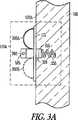
図3A〜3Bは、無線電気刺激システムに含まれうる無線電気刺激ノード110Aまたは「シード(seed)」の実施例の少なくとも一部分を一般的に示す図である。無線電気刺激ノード110Aは、心筋組織102にまたは心筋組織102内に固定された心血管無線電気刺激ノードとして構成されうる。誘導エネルギーは、1つまたは複数の形状記憶または他の機械的支柱300A、300B、300C、300Dによって支持された誘導ピックアップ112に結合されうる。ある実施例では、図3Bに示すように、支柱300A、300C、300Dは、互いに対して120°の角度などで、円柱ハウジング310の周りに半径方向に配設されうる。図7は、機械的支持体と機械的支持体に取り付けられた別個の誘導ワイヤループの両方を備える誘導ピックアップ112の部分断面図の例を示す。別の実施例では、誘導ピックアップワイヤループ自体は、電気ピックアップと機械的支持体の両方として役立ち、組立体の複雑さを低減する。 3A-3B are diagrams generally illustrating at least a portion of a wireless
一部の実施例では、螺旋固定デバイス255などの組織取り付け機構は、円柱ハウジング310を心筋組織102に固定しうる。これは、ハウジング310のできる限り少ない部分を心筋組織102から突出したままにするという目的などで、心筋組織102内の所望の深さまで円柱ハウジング310を引っ張りうる。これは、心臓収縮中などに、他の組織に衝当する可能性を減少させるかまたは最小にしうる。シード110Aの全長は、心筋102の遠方側を貫入する可能性を減少させるかまたは最小にするように選択されうる。 In some examples, a tissue attachment mechanism such as a
ある実施例では、10mmの公称最小心筋壁厚を仮定すると、円柱ハウジング310は、2mm以下の径および5mm以下の長さを有するように構成され、それにより、円柱ハウジング310と、アノード260、カソード250、および固定デバイス255を足した全長は、10mmより小さく、心筋102の遠方側を貫通することを回避するのに十分に短い。一部の実施例では、ディスクリート内部電子コンポーネントが、円柱ハウジング310内に含まれうる。ハウジング310の内部電子コンポーネントは、サイズの低減のために選択され、とりわけ、1つまたは複数のディスクリート表面実装キャパシタ、ディスクリート表面実装抵抗器、またはディスクリート表面実装ダイオードなどを含みうる。ある実施例では、ハウジング310の容積を減少させるために、単一ダイオードが、半波整流器として使用されうる。 In one embodiment, assuming a nominal minimum myocardial wall thickness of 10 mm,
カソード電極250は、心筋組織102内に埋め込まれうる第1の電気刺激電極を提供しうる。いくつかの実施例では、固定デバイス255の全てまたは一部分は、心筋組織102の特定の深さに電気刺激をターゲッティングするために、電極250に導電的に結合されうる。アノード電極260は、たとえば電気刺激回路を完成するリターン経路を提供するために、他の心臓組織102または血液と接触状態になりうる第2の電気刺激電極を提供しうる。 The
たとえば、心内膜用途では、心血管無線電気刺激ノード110Aは、カテーテルの管腔を通して経管的になどで、1つまたは複数の血管を介して心臓の内部に対する血管内送出のために構成され、心筋102内に埋め込まれ、左心室自由壁などの心内膜壁102Aに貫入しうる。アノード260と接触状態の血液は、カソード250に結合する心筋102の収縮性電気刺激(たとえば、ペーシング)を可能にする電気刺激エネルギーのための導電性経路を提供しうる。 For example, in endocardial applications, the cardiovascular wireless
一部の実施例では、埋め込み中にシード110Aの操作を可能にするために(たとえば、血管内送出システムの一部としてシード110Aにアクチュエータ組立体を固定するために)リテイナ軸265が含まれうる。 In some embodiments, a
支柱300A〜300Dは、誘導ピックアップ112についてほぼ円形のループ形状を柔軟に維持しながら、円柱ハウジングの所望の挿入深さに対処するために、NiTi(ニチノール)化合物などのばね様の(たとえば、自己拡張型または自己解放型)柔軟形状記憶材料から構築されうる。一部の実施例では、支柱300A〜300Dは、NiTi(ニチノール)化合物などの形状記憶材料でできた機械的支持体を備える誘導ピックアップ112に溶接されるかまたは付着されうる。 The
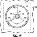
図4A〜4Bは、図3A〜3Bと同様であるが、無線電気刺激システムに含まれうる無線電気刺激ノード110Bの別の実施例の少なくとも一部分を一般的に示す。1つまたは複数の支柱400A〜400Dまたは返し(barb)構造455A〜455Bの組合せは、たとえば心臓組織102内へのシード110Bの固定を提供しうる。これらの実施例では、心筋102内への所定の深さの貫入を確立するために、回転は必要とされない。ハウジング410は、心筋内の貫入と反対側の心外膜壁を貫通することを回避するために、所望の深さまで組織102内に押込まれうる。図4A〜4Bの実施例では、ハウジング410は、円柱として示されるが、ハウジングの実際の断面はまた、インプラント送出カテーテル内での回転を阻止するかまたは防止するなどのために、多角形として構成されうる。 4A-4B are generally similar to FIGS. 3A-3B, but generally illustrate at least a portion of another embodiment of a wireless
埋め込み深さは、図4Aの実施例で示すように、ハウジング410から外側に延在する「J」形状ループまたはフックを提供するように支柱400A〜400Dを修正することなどによって制御されるかまたは制限されうる。シード110Bがさらに心筋102に貫入するにつれて、最終的に、支柱400A〜400Dは、さらなる挿入を制限しうる(たとえば、「J」形状ループが心臓壁102Aに衝突すると、挿入力が実質的に増加する)。側面返し455A〜455Bは、それほどの力がない状態で、シード110Bの除去を阻止するかまたは防止するために含まれうる。こうして、所定の深さが、得られるかまたは維持されうる。一部の実施例では、返し455A〜455Bは、シード110Bの埋め込み、除去、または引き込みのうちの1つまたは複数を容易にするために、埋め込み中などに、外側に拡張するかまたは内側に引込むように構成されうる。 The embedding depth is controlled, such as by modifying
たとえば、図4Aに示すようなポイントタイプカソード電極450および対応するアノード電極460を含む種々の異なる電気刺激電極形状が使用されうる。
支柱400A〜400Dは、たとえば図4Aに示すように、誘導ピックアップ112Bの断面に巻き付くかまたは断面を取り囲むことなどによって、誘導ピックアップ112Bに機械的に固定されうる。支柱400A〜400Dを機械的に結合する他の技法は、ハウジング410、誘導ピックアップ112Bなどの1つまたは複数に支柱400A〜400Dの1つまたは複数を溶接するかまたは付着させることを含みうる。For example, a variety of different electrical stimulation electrode shapes can be used, including a point-
The
一般的に、埋め込み中に血管内送出システムのアクチュエータコンポーネントにシード110Bを一時的に固定するために、リテイナ軸465が設けられうる。
一部の実施例では、図3A、3B、4A、4Bに示すシード110Aおよび110Bの1つまたは複数の要素は、血塊または血栓形成を抑制するために、抗凝固剤または他の処置剤をコーティングされうる。一部の実施例では、シード110A、110Bの1つまたは複数の要素は、組織内部成長を増大させるために、表面処理で仕上げられうる。一部の実施例では、シード110A、110Bは、組織102内に組込まれうる。こうした埋め込みは、血栓塞栓症の可能性を低減し、また同様に、所望の電気刺激を達成する閾値エネルギーを低減させうる(たとえば、心筋ペーシング閾値電圧の低減)。In general, a
In some embodiments, one or more elements of
組織内部成長増大処理の例は、表面粗化またはテクスチャリングあるいは1つまたは複数の他の孔隙率増大処理を含む。組織内部成長増大表面仕上げで処理されうる要素の例は、支柱構造(複数可)300A〜300D、400A〜400D、誘導ピックアップ112Aまたは112B、円柱ハウジング310または410などを含む。 Examples of tissue ingrowth enhancement processes include surface roughening or texturing or one or more other porosity augmentation processes. Examples of elements that can be treated with a tissue ingrowth enhancing surface finish include strut structure (s) 300A-300D, 400A-400D,
いくつかの実施例では、シード110Aおよび110Bの1つまたは複数の要素は、x線医療イメージング中における埋め込まれたコンポーネントの可視性を高めるためなどに、x線不透過性のために選択されうる1つまたは複数の材料を含みうる。 In some examples, one or more elements of
図5は、カテーテル570によって形成される管腔571を通って、無線電気刺激ノードハウジング510を搬送するかまたは通過させるなどのための、細長い血管内送出カテーテル570を含む無線電気刺激システムの少なくとも一部分の実施例を一般的に示す部分断面図である。 FIG. 5 illustrates at least a portion of a wireless electrical stimulation system that includes an elongated
一部の実施例では、鎖骨下静脈または大腿動脈を介して、静脈アクセスが達成されうる。たとえば、ガイドカテーテルが心臓102Aの心内膜領域に対するアクセスを達成すると、たとえば図5に示す送出カテーテル570が、ガイドカテーテルの管腔を通って経管的に通過させられうる。送出カテーテル570は、心臓組織ターゲット102に近い端部で開放状態でありうる。送出カテーテル570は、心血管無線電気刺激ノードハウジング510、拡張可能な誘導ピックアップ512、および1つまたは複数の拡張可能な支柱500A、500Bが、カテーテル571を介して1つまたは複数の血管を通して送られ、組織ターゲット102において心臓内に完全に心内膜に埋め込まれることを可能にするように、管腔571を形成する中空断面積が十分に大きくなりうる。 In some examples, venous access can be achieved via the subclavian vein or the femoral artery. For example, once the guide catheter has achieved access to the endocardial region of the
シードハウジング510の回転位置およびシードハウジング510の送出カテーテル570の長さに沿う位置は、ある実施例では、中空柔軟アクチュエータ572などによって操作されうる。アクチュエータ572は、シードハウジング510に接続されうるリテイナピン565に機械的に結合されうる。指状アダプタ574は、リテイナピン565に係合し、ロック用ワイヤ573を使用することなどによって、リテイナピン565を指状アダプタ574上の対応する窪みに変位させるために使用されうる。 The rotational position of the
身体の外側の送出カテーテルの遠位端において、アクチュエータ572に回転または併進(たとえば、摺動)力を加えるなどのために、プランジャまたは他の同様なマニピュレータが使用されうる。たとえば、螺旋ティン固定デバイス555が使用される場合、アクチュエータ572は、シードハウジング510の埋め込み中に所望の深さを達成するなどのために、心筋組織102内にティン555をねじ込むための回転力をシードハウジング510に伝達しうる。 A plunger or other similar manipulator may be used to apply a rotational or translational (eg, sliding) force to the
埋め込み手技中に、1つまたは複数の支柱500A、500Bは、シードの機械的ハウジング510に誘導ピックアップ512を結合するのに使用されうる。支柱500A、500Bは、送出中に断面積を減少させるなどのために、折畳まれたまたは圧壊された形態で送出されうる。図5に示すような実施例では、支柱500A、500Bおよび誘導ピックアップ512は、ハウジング510の本体に平行に直線状に折畳まれうる。別の実施例では、埋め込み中の全組立体の正味の長さをさらに減少させるために、支柱500A、500Bおよび誘導ピックアップ512は、ハウジング510に螺旋状に巻き付けられうる。固定デバイス555の所望の深さが達成されると、ロック用プルワイヤ573が引っ張られうる。たとえば、送出カテーテル570の遠位端において独立したマニピュレータに取り付けられる場合、プルワイヤ573は、マニピュレータを引っ張ることによって取外されうる。ロック用プルワイヤ573が引っ張られてリテイナピン565から切離されると、送出カテーテル570およびアクチュエータロッド572の全体が、心臓組織壁102Aから離れるように引っ張られうる。これは、シードハウジング510および固定具555が留まることを可能にする。 During the implantation procedure, one or
図6は、図5と同様であるが、プルワイヤ573の除去、送出カテーテル570の、管腔571などの中空領域を通したアクチュエータロッド572および指状アダプタ574の引き込み、および、心臓組織壁102Aからのカテーテル570の引き込みを含む、無線電気刺激システムの少なくとも一部分の実施例を一般的に示す部分断面図である。この実施例では、リテイナピン565は、もはや捕捉的でなく、したがって、シード組立体110Cは、心臓組織ロケーション102A、102に留まる。 FIG. 6 is similar to FIG. 5 except that the
一部の実施例では、送出カテーテル570が心臓組織壁102Aから離れるように引っ張られると、誘導ピックアップ512は、たとえば2センチメートルの外径まで拡張しうる。図5に示すように折畳まれるときの誘導ピックアップ512のサイズは、図6に示すように拡張したときの誘導ピックアップ512のサイズに関連しうる。誘導ピックアップ512の拡張した外径は、送出カテーテル570を使用した血管内送出を可能にするように選択されうる。 In some embodiments, when the
送出カテーテル570の、管腔571などの中空領域から切離されると、形状記憶機械的支柱500A、500Bは、自己拡張型形状記憶材料を使用することなどによって、誘導ピックアップ512を拡張させうる。ある実施例では、さらなる拡張力および形状記憶が、支柱500A〜500Bから分離しうる機械的支持体を備える誘導ピックアップ512自体によって提供されうる。誘導ピックアップおよび誘導アンテナ構成の実施例については図7〜9を参照されたい。 When disconnected from a hollow region, such as
図3A〜3Bおよび図4A〜4Bと同様に、固定デバイス555は、心筋102内の所定の深さなどにシード110Cを保持するのに役立ちうる。アノード電極550およびカソード電極560は、電気刺激エネルギーを提供する。 Similar to FIGS. 3A-3B and FIGS. 4A-4B, the
図7は、誘導組立体700を含む無線電気刺激システムの少なくとも一部分の実施例を一般的に示す部分断面図である。この実施例では、誘導組立体700は、ワイヤループの巻線710A、710Bおよび機械的支持体705を含む。この実施例では、ワイヤループ巻線710A、710Bを囲むなどのために、局所封止剤720が提供されうる。いくつかの実施例では、機械的支持体705とワイヤループ巻線710A、710Bの両方を囲むなどのために、バルク封止剤730が提供されうる。組立体700の断面図は、(図3A〜3Bに示すような)シードデバイスの一部分として含まれる誘導ピックアップ、または、たとえば(図1に示すような)無線エネルギー源の一部分として含まれる誘導アンテナを記述しうる。 FIG. 7 is a partial cross-sectional view generally illustrating an example of at least a portion of a wireless electrical stimulation system including a
図7に示す実施例では、複数の巻線710A、710Bが、機械的支持体705に隣接してまたはその近くに配設されうる。巻線710A、710Bは、柔軟絶縁ワイヤで構築されうる。個々の巻線710A、710Bは、それ自体、向上した柔軟性を提供するなどのために非絶縁ワイヤの複数のストランドで構築されうる。ある実施例では、図12の実施例に関して以下で説明されるように、柔軟性と向上した磁気性能を提供するなどのためにリッツ(Litz)ワイヤ(たとえば、銀ワイヤの複数のストランドを備える)が選択されうる。別の実施例では、絶縁銀ワイヤが、ワイヤループ710A、710Bの1つまたは複数のために使用されうる。 In the embodiment shown in FIG. 7, a plurality of
図示する実施例では、封止剤720は、個々のワイヤループ710A、710B間の巻線間エリア内への血液または水分の進入を阻止するかまたは防止するのに役立ちうる。封止剤720はまた、巻線ループ710A、710Bの相対的な間隔および位置を保持するなどのために、巻線ループ710A、710Bを共に固着するのに役立ちうる。水分の進入を防止し、巻線を安定化することは、経時的なまたは埋め込み中などの電気性能の変動を低減するのに役立ちうる(たとえば、誘導組立体のインダクタンスおよび巻線間キャパシタンスが安定状態のままになりうる)。 In the illustrated embodiment, the
埋め込み中の拡張を容易にするために、柔軟性など弾性のため、または、バルク封止剤730が使用されない場合など生体適合性のための、封止剤720が選択されうる。医療等級シリコーンなどの封止剤720用の材料は、弾性と生体適合性の両方を提供しうる。 A
いくつかの実施例では、バルク封止剤730は、誘導ピックアップ組立体700を保護すると共に、誘導ワイヤループ710A、710Bを機械的支持体705に固定するのに役立ちうる。バルク封止剤の例は、生体適合性オーバモールディング化合物、ヒ−トシンクチュービング、シリコーン、または、柔軟性および生体適合性のために選択されうる他の材料を含みうる。図7に示す実施例における、誘導組立体700の最も外側の露出表面、バルク封止剤730は、図3A〜3B、4A〜4Bに関して説明した仕上げまたは処理と同様に、組織内部成長を促進する物質か、抗凝固物質か、または両方で処理されうる。封止剤は、種々の考えられるオーバモールディングまたは被覆材料を含みうる。封止剤は、完全にボイドが無い空間をもたらす必要はない。たとえば、封止剤は、組立体700の1つまたは複数の他の要素の貫入を許容しうる。たとえば、一部の実施例では、先の図で述べたような1つまたは複数の支柱構造は、機械的支持体705に対する機械的または他の付着を達成するなどのために、封止材料730に貫入しうる。いくつかの実施例では、こうした支柱構造は、封止材料730に機械的にまたはその他の方法で付着しうる。いくつかの実施例では、多孔性のまたは粗化された外部表面が、組織内部成長を促進するなどのために、封止材料730上に意図的に生成されうる。いくつかの実施例では、単一の絶縁ワイヤ巻線ループ710Aだけが、別個の支持体が無い状態で使用される。 In some embodiments,
図8は、機械的支持体800または「コア(core)」を取り囲むために同軸に巻かれた螺旋ワイヤループ802を含む無線電気刺激システムの少なくとも一部分の実施例の斜視図を一般的に示す図である。この実施例では、非導電性ギャップまたは不連続部801が、機械的支持ループ800に沿って配置される。ギャップ801は、導電性材料がコア800に使用されるときに、コア800の「短絡2次効果(shortened secondary effect)」によって誘発される損失を低減しうる。こうした損失は、たとえば機械的支持ループ800における誘発された渦電流のせいでありうる。短絡2次効果は、コア800が、ワイヤループ802に磁気的に結合した短絡した変圧器巻線のように働くときに起こる。こうした損失の電気的作用は、動作時における効率の低下または高Q誘導アンテナ/誘導ピックアップ対の脱同調を含みうる。これは、「アンテナ引込み(antenna pulling)」と呼ばれうる。ギャップ801を導入することは、コア800によって形成された誘発電流ループを解体し、損失またはアンテナ引込み効果を低減しうる。 FIG. 8 generally illustrates a perspective view of an example of at least a portion of a wireless electrical stimulation system that includes a
図9は、図8と同様であるが、機械的支持体900の面上に螺旋で巻かれたワイヤループ902を含み、かつ、図8に関して先に説明したギャップと同様の非導電性ギャップ901を含む無線電気刺激システムの少なくとも一部分の実施例の斜視図を一般的に示す図である。図8〜9に示す実施例は、誘導ワイヤループ802、902の異なる物理的配置構成が、機械的支持体800、900などに関して使用されうることを実証する。一部の実施例では、図8〜9は、心内膜ロケーション内または冠血管系内に埋め込まれることが可能な生体適合性誘導アンテナまたは誘導ピックアップ組立体を形成するなどのために、図7で説明した封止剤または表面処理と組合されうる。 FIG. 9 is similar to FIG. 8, but includes a
図10は、図1と同様であるが、患者身体1010内部の心臓ロケーション102における1つまたは複数の埋め込み型無線電気刺激ノード1005A、1005Bによって捕捉されうる時間的に変化する磁束1014を生成するように構成される外部デバイス1040を含む無線電気刺激システム1000の少なくとも一部分の実施例を一般的に示す図である。たとえば、外部デバイス1040は、治療コントロールユニットおよび無線エネルギー送信源を備える医師プログラマユニットでありうる。いくつかの実施例では、外部デバイス1040は、オンデマンドでまたは外部デバイス1040によって確立されたプログラムに従って歩行可能な(ambulatory)電気刺激治療を提供するなどのために、患者によって外部に装着されるデバイスを含みうる。いくつかの実施例では、(たとえば、経皮的冠動脈インターベンションまたは他の関連する処置と共に)短期的な電気刺激治療が所望される場合などに、外部デバイス1040は、電気刺激治療が所望される短い期間などに、ベッド、ベスト、帽子、髪、または、患者によって装着されるかまたは患者の近くに配置されうる他の装置内に組込まれうる。 FIG. 10 is similar to FIG. 1 but generates a time-varying
図11は、無線電気刺激ノードを含む、実施されうるプロセス1100の少なくとも一部分の実施例を一般的に示す図である。いくつかの実施例では、無線電気刺激ノードは、患者の身体内のロケーションに送出される1105。自己拡張型材料を使用して、あるいは、図5〜6に示すカテーテル送出システムを通して通過させられるような、1つまたは複数のマニピュレータを使用してなどで、誘導ピックアップは、そのロケーションにおいて拡張される1110。磁束が、別個の誘導アンテナによって生成され、誘導ピックアップに結合される1115。誘導ピックアップで誘発される結果として得られる電圧は、エネルギー捕捉をもたらす1120。捕捉されたエネルギーは、貯蔵されうるか、または、コマンドによって即座に送出されうる。いくつかの実施例では、図11に示すように、無線電気刺激ノードは、治療コントロールユニットからのコマンドなどの、組織電気刺激を始動するコマンドを待ちうる1125。コマンドを受信すると、無線電気刺激ノードは、その後、組織電気刺激を送出する1130。一部の実施例では、コマンドおよび電気刺激用のエネルギーを提供する時間的に変化する磁束は同じでありうる(たとえば、適切な磁束信号の受信によって、たとえば、図2に関して上述したように、所定の周波数範囲内で、または、所定の継続時間の間、ほぼ瞬時の電気刺激を提供する)。 FIG. 11 is a diagram generally illustrating an example of at least a portion of a
図12は、無線電気刺激ノード誘導ピックアップ受信機で予測される出力電圧(「Vcalc」)の解析の実施例を示すプロットである。対応する実際の測定される出力電圧(「Vmeas」)は、無線電気刺激ノードの実験プロトタイプの誘導ピックアップ受信機の出力電極にわたって測定されうる。測定される出力電圧(「Vmeas」)は、試験負荷に結合される、無線電気刺激ノードの電気刺激電極にわたって測定される電気刺激波形の立ち上がりエッジに関して測定されるピーク電圧に相当する。 FIG. 12 is a plot illustrating an example of an analysis of output voltage (“Vcalc”) predicted by a wireless electrical stimulation node inductive pickup receiver. The corresponding actual measured output voltage (“Vmeas”) may be measured across the output electrode of the inductive pick-up receiver of the experimental prototype of the wireless electrical stimulation node. The measured output voltage (“Vmeas”) corresponds to the peak voltage measured with respect to the rising edge of the electrical stimulation waveform measured across the electrical stimulation electrode of the wireless electrical stimulation node coupled to the test load.
両方の電圧(「Vcalc」、「Vmeas」)は、(1)エネルギー送信源誘導アンテナ(送信機)と(2)無線電気刺激ノード誘導ピックアップ(受信機)との間の間隔(たとえば、センチメートル単位)に対してプロットされうる。 Both voltages (“Vcalc”, “Vmeas”) are the distance (eg, centimeters) between (1) the energy source inductive antenna (transmitter) and (2) the wireless electrical stimulation node inductive pickup (receiver). Unit).
図12に関して述べる実験プロトタイプを例として構築するのに使用される材料および電気パラメータは表1に述べられる。図12に示す計算された予測出力電圧(「Vcalc」)は、式(2)および表1に示す電気パラメータを使用して|VL|を計算することによって推定されうる。The materials and electrical parameters used to build the experimental prototype described with respect to FIG. 12 as an example are set forth in Table 1. The calculated predicted output voltage (“Vcalc”) shown in FIG. 12 may be estimated by calculating | VL | using equation (2) and the electrical parameters shown in Table 1.
電力結合効率ηは、表1の電気パラメータなどを使用して式(1)から計算されうる。ペーシングベンチマークとして、たとえば8cmのコイル間隔において|VL|=3.6ボルトの出力電圧を仮定すると、出力電力は、ペーシングパルスの継続時間について、|VL|2/(2RL)=〜0.013ワットとして計算されうる。The power coupling efficiency η can be calculated from equation (1) using the electrical parameters of Table 1 and the like. Assuming an output voltage of, for example, | VL | = 3.6 volts at a coil spacing of 8 cm as a pacing benchmark, the output power will be | VL | 2 / (2RL ) = ˜0 for the duration of the pacing pulse. Calculated as .013 Watts.
平均電力出力は、この値をデューティサイクルで乗算することによって計算されうる。心臓ペーシングパルス継続時間の実施例は500μsecであり、サイクル長の実施例は850msec(〜70心拍動/分に相当する)である。結果として得られるデューティサイクルは0.00059であり、3.6ボルトペーシング振幅についての平均出力電力は約7.5μWである。 The average power output can be calculated by multiplying this value by the duty cycle. An example of cardiac pacing pulse duration is 500 μsec and an example of cycle length is 850 msec (corresponding to ~ 70 heartbeats / minute). The resulting duty cycle is 0.00059 and the average output power for a 3.6 volt pacing amplitude is about 7.5 μW.
入力電力は、計算された出力電力、この実施例の場合、7.5μWを、式(1)から計算された電力結合効率ηで割り、たとえば送信機内のマイクロプロセッサまたはマイクロコントローラによって消費される静電力を加算することによって計算されうる。こうした静電力は、例証的な実施例では、0.425μWでありうる。最小3.6ボルトペーシング振幅を仮定すると、図12は、表1の実施例で指定される電気パラメータを仮定して、送信機コイルと受信機コイルとの間のある範囲の間隔について電力結合効率η(パーセント(%)単位)を示す。 The input power is calculated output power, in this example 7.5 μW divided by the power coupling efficiency η calculated from equation (1), for example static power consumed by the microprocessor or microcontroller in the transmitter. It can be calculated by adding the power. Such an electrostatic force may be 0.425 μW in the illustrative example. Assuming a minimum 3.6 volt pacing amplitude, FIG. 12 illustrates the power coupling efficiency for a range of spacing between the transmitter and receiver coils, assuming the electrical parameters specified in the example of Table 1. η (percent (%) unit) is shown.
電池のワット−時間容量を出力電力使用で割ることは、電池寿命の推定値を与える。25グラムリチウム充電式電池は、約12ワット−時間の有効(回復可能)エネルギーを含む。図13は、表1の実施例で指定される電気パラメータを仮定し、かつ、例証的な実施例では、埋め込み型送信機電池にとって利用可能な12ワット−時間充電を仮定すると、送信機コイルと受信機コイルとの間の種々の間隔についての電池寿命(月単位)を示す。 Dividing the battery watt-hour capacity by the output power usage gives an estimate of the battery life. A 25 gram lithium rechargeable battery contains about 12 watts-hour of available (recoverable) energy. FIG. 13 assumes the electrical parameters specified in the example of Table 1 and, in the illustrative example, assumes 12 watt-hour charging available for the implantable transmitter battery, Fig. 4 shows the battery life (in months) for various intervals with the receiver coil.
図13に示す実施例では、約3ヶ月以上の電池寿命は、3.6ボルト以下のペーシング出力電圧における8cm以下の受信機間隔について実行可能でありうる。
受信電力は、送信機コイルの平面と受信機コイルの平面との間の角度が、ゼロ度からずれるにつれて減少する(結合効率κを減少させる)ことになり、向き感度をもたらす。一部の実施例では、複数の平面内の複数の送信コイルおよびさらに単一平面内の複数のコイルは、こうした向き感度を減少させるのに役立ちうる。複数の受信機コイルは、送信機の遠方場においてさらなるエネルギーをほとんど消費せず、複数の受信機が誘導送信機の近くで動作する実施例を可能にする。In the embodiment shown in FIG. 13, a battery life of about 3 months or more may be feasible for a receiver spacing of 8 cm or less at a pacing output voltage of 3.6 volts or less.
The received power will decrease (decrease the coupling efficiency κ) as the angle between the plane of the transmitter coil and the plane of the receiver coil deviates from zero degrees, resulting in orientation sensitivity. In some embodiments, multiple transmit coils in multiple planes and even multiple coils in a single plane can help reduce such orientation sensitivity. Multiple receiver coils consume little additional energy in the far field of the transmitter, allowing embodiments where multiple receivers operate near the inductive transmitter.
先に説明したいくつかの実施例では、たとえば拡張型心臓の場合でも、右心室(RV)中隔に対して設置されうる送信機誘導アンテナと、左心室(LV)自由壁上の心内膜に配置されうる1つまたは複数のループ受信機について、8cmの有効範囲が適しうる。一部の実施例では、心尖LV自由壁上の誘導受信機は、RV内の送信機または外部送信機から4〜6cmだけ分離されうる。 In some of the embodiments described above, a transmitter guiding antenna that can be placed against the right ventricular (RV) septum and the endocardium on the left ventricular (LV) free wall, for example in the case of a dilated heart. An effective range of 8 cm may be suitable for one or more loop receivers that may be placed in In some embodiments, inductive receivers on the apical LV free wall can be separated by 4-6 cm from transmitters in the RV or external transmitters.
図14は、図1と同様であるが、皮下誘導アンテナを含む無線電気刺激システムの少なくとも一部分の実施例を一般的に示す図である。一部の実施例では、埋め込み型送信機誘導アンテナ1408は、心臓102内の心内膜に配置される必要はなく、患者1010の胸部上で皮下に、または、心臓102に隣接する心膜空間内に設置されてもよい。 FIG. 14 is a diagram generally illustrating an example of at least a portion of a wireless electrical stimulation system similar to FIG. 1 but including a subcutaneous induction antenna. In some embodiments, the implantable transmitter
誘導アンテナ給電ワイヤ組立体1406は、(1)給電ワイヤ組立体1406の遠位端における誘導アンテナ1408と、(2)給電ワイヤ組立体1406の近位端における埋め込み型心臓調律管理デバイス1420との間に電気結合されうる。一部の実施例では、誘導アンテナ1408は、電気刺激電極組立体1005A、1005Bによって捕捉される時間的に変化する磁束を生成する。 Guide antenna
一部の実施例では、誘導アンテナ1408および給電ワイヤ組立体1406は、たとえば心内膜柔軟リード線システムと同様に構築されうる(たとえば、生体適合性シリコーン外部ジャケットは、給電ワイヤ組立体1406の外側表面のために選択され、互いに絶縁された1つまたは複数のコイル状金属導体は、誘導アンテナ1408に電力供給するために組立体1406の内部で使用されうる)。
追加事項
上述した説明は、詳細な説明の一部を形成する添付図面に対する参照を含む。図面は、例証として、本発明が実施されうる特定の実施形態を示す。これらの実施形態はまた、本明細書で「実施例」とも呼ばれる。こうした実施例は、示し述べた要素以外の要素を含みうる。しかし、本発明は、示し述べる要素だけがそこで提供される実施例も企図する。In some examples,
Additional Notes The above description includes references to the accompanying drawings, which form a part of the detailed description. The drawings show, by way of illustration, specific embodiments in which the invention can be practiced. These embodiments are also referred to herein as “Examples”. Such embodiments may include elements other than those shown and described. However, the present invention also contemplates embodiments in which only the elements shown and described are provided therein.
本文書で参照される全ての出版物、特許、および特許文書は、参照により個々に組込まれるかのように、参照によりその全体が本明細書に組込まれる。本文書と、参照により組込まれる文書との間に矛盾する使用法がある場合、組込まれる参照(複数可)における使用法は、本文書の使用法を補助するものと考えられるべきである。すなわち、両立しない矛盾については、本文書における使用法が規制する。 All publications, patents, and patent documents referenced in this document are hereby incorporated by reference in their entirety as if individually incorporated by reference. If there is a conflicting usage between this document and the document incorporated by reference, the usage on the incorporated reference (s) should be considered to assist in the usage of this document. In other words, the usage in this document regulates inconsistencies.
本文書において、用語「1つの」は、特許文書で一般的であるように、「少なくとも1つ」または「1つまたは複数」の任意の他の例または使用と独立に、1つまたは2つ以上を含むために使用される。本文書では、用語「または」は、非排他的な「または」を指すのに使用される。したがって、特に指示されない限り、「AまたはB」は「AであるがBではない」、「BであるがAではない」および「AおよびB」を含む。添付特許請求の範囲では、用語「含む」は、用語「備える」の平易な等価物として使用される。同様に、添付特許請求の範囲では、用語「含む」および「備える」は、無制限(open−ended)である、すなわち、特許請求項の範囲においてこうした用語の後に挙げられる要素以外の要素を含むシステム、デバイス、製品またはプロセスは、依然として特許請求項の範囲内に入ると考えられる。さらに、添付特許請求の範囲では、用語「第1の」、「第2の」および「第3の」などは、単にラベルとして使用され、その物体に対して数値要件を課すことを意図されない。 In this document, the term “a”, as is common in patent documents, is one or two independent of any other example or use of “at least one” or “one or more”. Used to include the above. In this document, the term “or” is used to refer to a non-exclusive “or”. Thus, unless otherwise indicated, “A or B” includes “A but not B”, “B but not A” and “A and B”. In the appended claims, the term “comprising” is used as a plain equivalent of the term “comprising”. Similarly, in the appended claims, the terms “comprising” and “comprising” are open-ended, that is, systems that include elements other than those listed after such terms in the claims. , Devices, products or processes are still considered to be within the scope of the claims. Furthermore, in the appended claims, the terms “first”, “second”, “third” and the like are used merely as labels and are not intended to impose numerical requirements on the object.
本明細書で述べる方法実施例は、少なくとも部分的に、機械実施式であるかまたはコンピュータ実施式でありうる。一部の実施例は、上記実施例で述べた方法を実施するよう電子デバイスを構成するように働く命令をエンコードされるコンピュータ読取り可能媒体または機械読取り可能媒体を含みうる。こうした方法の実施態様は、マイクロコード、アセンブリ言語コード、高レベル言語コード、または同様なものなどのコードを含みうる。こうしたコードは、種々の方法を実施するためのコンピュータ読取り可能命令を含みうる。コードは、コンピュータプログラム製品の所定部分を形成してもよい。さらに、コードは、実行中、または、他の時点で、1つまたは複数の揮発性または不揮発性コンピュータ読取り可能媒体上に触知可能に格納されてもよい。これらのコンピュータ読取り可能媒体は、ハードディスク、取外し可能磁気ディスク、取外し可能光ディスク(たとえば、コンパクトディスクおよびデジタルビデオディスク)、磁気カセット、メモリカードまたはスティック、ランダムアクセスメモリ(RAM)、読取り専用メモリ(ROM)、ならびに同様なものを含んでもよいが、それに限定されなくてもよい。 The method embodiments described herein can be machine-implemented or computer-implemented, at least in part. Some embodiments may include computer-readable or machine-readable media encoded with instructions that serve to configure the electronic device to perform the methods described in the above embodiments. Such method implementations may include code such as microcode, assembly language code, high-level language code, or the like. Such code may include computer readable instructions for performing various methods. The code may form a predetermined part of the computer program product. Further, the code may be tactilely stored on one or more volatile or non-volatile computer readable media during execution or at other times. These computer readable media include hard disks, removable magnetic disks, removable optical disks (eg, compact disks and digital video disks), magnetic cassettes, memory cards or sticks, random access memory (RAM), read only memory (ROM). As well as the like, but is not limited thereto.
先の説明は、例証的であり、制限的でないことを意図される。たとえば、上述した実施例(またはその1つまたは複数の態様)は、互いに組合せて使用されてもよい。先の説明を検討することによって、他の実施形態が当業者などによって使用されうる。要約は、読者が技術的開示の特質を迅速に確認することを可能にするために提供される。要約は、特許請求項の範囲または意味を解釈するかまたは制限するために使用されることがないという理解によって提出される。同様に、上記詳細な説明では、種々の特徴は、開示を簡素化するために共にグループ化されてもよい。このことは、未請求の開示特徴が、任意の特許請求項に必須であることを意図するものとして解釈されるべきでない。むしろ、本発明の主題は、特定の開示される実施形態の全ての特徴より少ない特徴に存在する可能性がある。そのため、添付特許請求項は、詳細な説明に組込まれ、各請求項は、別個の実施形態として自分自身を主張する。本発明の範囲は、添付特許請求の範囲を参照して、添付特許請求の範囲が権利を与えられる等価物の全範囲と共に確定されるべきである。
[付記1]
無線電気刺激システムであって、
誘導アンテナを含み、時間的に変化する磁束を生成するように構成された無線エネルギー送信源と、
経皮経管的カテーテル送出システムを使用して埋め込み可能であるように寸法決定されかつ形作られた心血管無線電気刺激ノードであって、
組織電気刺激を生成するのに少なくとも十分な誘導結合エネルギーを前記誘導アンテナから捕捉するように構成された受信機回路であって、該受信機回路は、前記時間的に変化する磁束を結合するように構成された機械的に拡張可能な誘導ピックアップであって、1.1より小さい比透磁率を含むコア材料を含む前記機械的に拡張可能な誘導ピックアップを含む、前記受信機回路と、
前記受信機回路に結合され、前記受信機回路によって捕捉されたエネルギーを、所定の組織電気刺激波形として送出するように構成され、少なくとも1つの組織電気刺激電極を含む組織電気刺激回路と
を含む、前記心血管無線電気刺激ノードと、
組織電気刺激ノードに通信可能に結合され、前記組織電気刺激電極による組織電気刺激の送出を始動するように構成される治療コントロールユニットと
を備えるシステム。
[付記2]
前記心血管無線電気刺激ノードは、血管内送出のために構成されかつ寸法決定されている、付記1に記載のシステム。
[付記3]
前記受信機回路は、
前記時間的に変化する磁束によって転送される誘導結合エネルギーを貯蔵するように構成されるエネルギー貯蔵デバイスを含み、
前記エネルギー貯蔵デバイスは、最大限1ミリジュールのエネルギーを貯蔵するように構成され、
前記組織電気刺激は、前記誘導結合エネルギーの転送の打切り後1分以下で、前記エネルギー貯蔵デバイスの枯渇により阻止される、付記1乃至2のいずれか1項に記載のシステム。
[付記4]
前記組織電気刺激回路は、
前記受信機回路と前記組織刺激電極との間に結合された整流器と、
前記組織刺激電極と前記受信機回路との間に結合された直流遮断デバイスと
を含み、
前記少なくとも1つの組織電気刺激電極は、心臓組織に結合されるように構成されるカソードを含み、
前記少なくとも1つの組織電気刺激電極は、心臓組織に結合されるように構成されるアノードを含み、
前記組織電気刺激回路は、500オーム等価負荷に結合される場合、0.4ミリ秒のパルス幅の少なくとも2.5Vピーク振幅の電気刺激パルスを、前記アノードと前記カソードとの間で生成することが可能であるように構成される、付記1乃至3のいずれか1項に記載のシステム。
[付記5]
前記心血管無線電気刺激ノードは、
機械的に拡張可能な誘導ピックアップであって、
絶縁ワイヤループと、
前記絶縁ワイヤループに機械的に結合する形状記憶材料のループであって、形状記憶材料のループの少なくとも一部分は非導電性である、前記形状記憶材料のループを含む拡張可能機械的支持体と
を含む前記機械的に拡張可能な誘導ピックアップと、
ハウジングであって、
前記絶縁ワイヤループに導電的に結合する受信機回路電荷貯蔵デバイスと、
前記組織電気刺激回路と
を含み、前記形状記憶材料のループによって包囲される空間内に配設される、前記ハウジングと、
形状記憶材料からなり、前記形状記憶材料のループを円柱ハウジングに固定するように構成される支柱と
を含む、付記1乃至4のいずれか1項に記載のシステム。
[付記6]
前記誘導ピックアップの少なくとも一部分を包囲するように構成される生体適合性誘電性封止剤を備える、付記5に記載のシステム。
[付記7]
前記無線エネルギー送信源は、前記時間的に変化する磁束のバーストパルス継続時間を変更するように構成され、前記組織電気刺激回路は、前記整流器の出力に結合される電圧クランプデバイスを含み、前記電気刺激パルスのエネルギー含有量は、前記電圧クランプデバイスの両端の電圧が実質的に電圧クランプデバイス閾値電圧以上である場合に、前記バーストパルス継続時間によって制御される、付記5乃至6のいずれか1項に記載のシステム。
[付記8]
前記誘導ピックアップは、拡張すると、2cm以下の最大外径になるように構成され、
前記ハウジングは、2mm以下の円柱径および5mm以下の長さから成り、
前記円柱ハウジングおよび心臓組織取り付け機構の全長は、10mmの公称最小心筋組織壁厚以下である、付記5乃至7のいずれか1項に記載のシステム。
[付記9]
前記無線エネルギー送信源は、500キロヘルツと5メガヘルツとを含む、500キロヘルツから5メガヘルツまでの周波数範囲内の所定の受信機共振周波数で前記時間的に変化する磁束を生成するように構成され、前記無線エネルギー送信源は、前記誘導結合エネルギーを、少なくとも1%の電力結合効率で送出するように構成される、付記1乃至8のいずれか1項に記載のシステム。
[付記10]
前記無線エネルギー送信源および前記治療コントロールユニットは共に、前記無線電気刺激ノードを含む患者の身体の外部に配置されるように構成される、付記1乃至9のいずれか1項に記載のシステム。
[付記11]
前記無線エネルギー送信源および前記治療コントロールユニットを含む電池駆動式埋め込み型心臓調律管理ユニットを備える、付記1乃至10のいずれか1項に記載のシステム。
[付記12]
前記無線エネルギー送信源は、
埋め込み型柔軟リード線を含み、前記埋め込み型柔軟リード線は、
埋め込み型無線電気刺激ノードの近くに配置されるように構成される遠位端と、
前記電池駆動式埋め込み型心臓調律管理ユニットのハウジングに、または、その近くに配置されるように構成される近位端と、
前記リード線の内部に配設され、かつ、前記電池駆動式埋め込み型心臓調律管理ユニットの前記ハウジングに導電的に結合される少なくとも2つのアンテナ給電導体と、
前記リード線の前記遠位端に配設され、かつ、前記リード線の前記近位端で前記少なくとも2つのアンテナ給電導体に導電的に結合される前記誘導アンテナと
を含み、
前記治療コントロールユニットは、前記少なくとも2つのアンテナ給電導体に電力供給するように構成される、付記11に記載のシステム。
[付記13]
方法であって、
心血管無線電気刺激ノードを身体内ロケーションに送出すること、
無線電気刺激ノード誘導ピックアップを拡張させること、
時間的に変化する磁束を生成すること、
前記時間的に変化する磁束を前記無線電気刺激ノード誘導ピックアップに結合させること、
無線電気刺激ノード誘導ピックアップワイヤループを1.1より小さい比透磁率のコア材料を用いて構成すること、
組織電気刺激を送出するのに少なくとも十分な誘導結合エネルギーを捕捉すること、
所定の組織電気刺激波形の送出の始動を制御すること、
始動に応答して、所定の組織電気刺激波形を送出すること
を含む方法。
[付記14]
血管経路を通して身体内ロケーションへ心血管無線電気刺激ノードを送出することを含む、付記13に記載の方法。
[付記15]
前記無線電気刺激ノードに含まれるエネルギー貯蔵デバイス内に前記誘導結合エネルギーを貯蔵すること、
前記エネルギー貯蔵デバイス内への1ミリジュールより大きいエネルギーの貯蔵を阻止すること、
前記時間的に変化する磁束を打切ること、
前記エネルギー貯蔵デバイスを枯渇させること、
前記エネルギー貯蔵デバイスを枯渇させることに応答して、前記時間的に変化する磁束の打切り後1分を越えて前記組織電気刺激の送出を阻止すること
を含む、付記13に記載の方法。
[付記16]
前記時間的に変化する磁束を整流すること、
カソードを心臓組織に結合させること、
アノードを心臓組織に結合させること、
500オーム等価負荷に結合されると、0.4ミリ秒のパルス幅の少なくとも2.5Vピーク振幅の電気刺激パルスを、前記アノードと前記カソードとの間で生成すること、
組織刺激電極と受信機回路との間で直流の通過を遮断すること
を含む、付記13に記載の方法。
[付記17]
前記誘導ピックアップワイヤループを絶縁すること、
前記誘導ピックアップワイヤループを形状記憶機械的支持体に機械的に結合させること、
心臓組織壁の近くで形状記憶拡張可能機械的支持体を所定のループ形状に拡張させること、
前記形状記憶拡張可能機械的支持体の周縁に沿って非導電性部分を形成すること、
前記形状記憶機械的支持体を円柱ハウジングに機械的に結合させること、
前記形状記憶機械的支持体によって包囲される空間内に前記円柱ハウジングを配設すること
を含む、付記16に記載の方法。
[付記18]
前記誘導ピックアップの少なくとも一部分を、生体適合性誘電性封止剤を用いて包囲することを含む、付記16に記載の方法。
[付記19]
前記時間的に変化する磁束のバーストパルス継続時間を変更すること、
前記時間的に変化する磁束を整流することによって生成される電圧をクランプすること、
電圧クランプデバイスの両端の電圧が実質的に電圧クランプデバイス閾値電圧以上である場合に、前記時間的に変化する磁束の前記バーストパルス継続時間を変更することによって、前記電気刺激パルスのエネルギー含有量を制御すること
を含む、付記17に記載の方法。
[付記20]
拡張時2cm以下の最大外径まで前記誘導ピックアップを拡張させること、
前記円柱ハウジングを2mm以下の径に制限すること、
前記円柱ハウジングを5mm以下の長さに制限すること、
前記円柱ハウジングおよび心臓組織取り付け機構の全長を、10mmの公称最小心筋組織壁厚以下に制限すること
を含む、付記17に記載の方法。
[付記21]
500キロヘルツと5メガヘルツを含む、500キロヘルツから5メガヘルツまでの周波数範囲内の所定の受信機共振周波数で前記時間的に変化する磁束を生成すること、
少なくとも1%の電力結合効率で前記誘導結合エネルギーを転送すること
を含む、付記13に記載の方法。
[付記22]
患者の身体の外部のロケーションから前記時間的に変化する磁束を生成すること、
前記患者の身体の外部のロケーションから組織電気刺激を始動させること
を含む、付記13に記載の方法。
[付記23]
電池駆動式埋め込み型心臓調律管理ユニットを身体内ロケーションに送出すること、
誘導アンテナを前記埋め込み型心臓調律管理ユニットに導電的に結合させること、
前記誘導アンテナを使用して前記時間的に変化する磁束を生成すること、
前記埋め込み型心臓調律管理ユニットを使用して組織電気刺激を始動させること
を含む、付記13に記載の方法。
[付記24]
埋め込み型無線電気刺激ノードの近くに埋め込み型柔軟リード線の遠位端を配置すること、
前記誘導アンテナを前記埋め込み型柔軟リード線の前記遠位端に機械的に結合させること、
電池駆動式埋め込み型心臓調律管理ユニット治療コントロールユニットのハウジングに、または、その近くに、心血管埋め込み型柔軟リード線の近位端を配置すること、
前記埋め込み型柔軟リード線内に少なくとも2つのアンテナ給電導体を配置すること、
前記電池駆動式埋め込み型心臓調律管理ユニット治療コントロールユニットのハウジングから前記誘導アンテナまで前記少なくとも2つのアンテナ給電導体を導電的に結合させること、
前記少なくとも2つのアンテナ給電導体に電力供給すること
を含む、付記23に記載の方法。The foregoing description is intended to be illustrative and not restrictive. For example, the above-described examples (or one or more aspects thereof) may be used in combination with each other. By reviewing the above description, other embodiments can be used by those skilled in the art and the like. A summary is provided to allow the reader to quickly ascertain the nature of the technical disclosure. The Abstract is submitted with the understanding that it will not be used to interpret or limit the scope or meaning of the claims. Similarly, in the above detailed description, various features may be grouped together to simplify the disclosure. This should not be interpreted as intending that an unclaimed disclosed feature is essential to any claim. Rather, the subject matter of the invention may reside in fewer than all features of a particular disclosed embodiment. Thus, the following claims are hereby incorporated into the Detailed Description, with each claim standing on its own as a separate embodiment. The scope of the invention should be determined with reference to the appended claims, along with the full scope of equivalents to which such claims are entitled.
[Appendix 1]
A wireless electrical stimulation system,
A wireless energy transmission source including an induction antenna and configured to generate a time-varying magnetic flux;
A cardiovascular wireless electrical stimulation node sized and shaped to be implantable using a percutaneous transluminal catheter delivery system comprising:
A receiver circuit configured to capture at least sufficient inductive coupling energy from the inductive antenna to generate tissue electrical stimulation, the receiver circuit configured to couple the time-varying magnetic flux. A mechanically expandable inductive pickup configured in the receiver circuit comprising the mechanically expandable inductive pickup including a core material including a relative permeability less than 1.1; and
A tissue electrical stimulation circuit coupled to the receiver circuit and configured to deliver energy captured by the receiver circuit as a predetermined tissue electrical stimulation waveform; and comprising at least one tissue electrical stimulation electrode
The cardiovascular wireless electrical stimulation node comprising:
A therapy control unit communicatively coupled to a tissue electrical stimulation node and configured to initiate delivery of tissue electrical stimulation by the tissue electrical stimulation electrode;
A system comprising:
[Appendix 2]
The system of claim 1, wherein the cardiovascular wireless electrical stimulation node is configured and dimensioned for intravascular delivery.
[Appendix 3]
The receiver circuit is
An energy storage device configured to store inductively coupled energy transferred by the time-varying magnetic flux;
The energy storage device is configured to store a maximum of 1 millijoule of energy;
The system according to any one of claims 1 to 2, wherein the tissue electrical stimulation is prevented by depletion of the energy storage device within 1 minute after the transfer of the inductive coupling energy is terminated.
[Appendix 4]
The tissue electrical stimulation circuit includes:
A rectifier coupled between the receiver circuit and the tissue stimulation electrode;
A DC blocking device coupled between the tissue stimulation electrode and the receiver circuit;
Including
The at least one tissue electrical stimulation electrode includes a cathode configured to be coupled to cardiac tissue;
The at least one tissue electrical stimulation electrode includes an anode configured to be coupled to cardiac tissue;
When the tissue electrical stimulation circuit is coupled to a 500 ohm equivalent load, it generates at least a 2.5 V peak amplitude electrical stimulation pulse between the anode and the cathode with a pulse width of 0.4 milliseconds. 4. The system according to any one of appendices 1 to 3, wherein the system is configured such that
[Appendix 5]
The cardiovascular electrical stimulation node is
A mechanically expandable inductive pickup,
An insulated wire loop;
An expandable mechanical support comprising a loop of shape memory material mechanically coupled to the insulated wire loop, wherein at least a portion of the loop of shape memory material is non-conductive;
Said mechanically expandable inductive pickup comprising:
A housing,
A receiver circuit charge storage device conductively coupled to the insulated wire loop;
The tissue electrical stimulation circuit;
And wherein the housing is disposed in a space surrounded by the loop of shape memory material;
A post made of shape memory material and configured to secure a loop of said shape memory material to a cylindrical housing;
The system according to any one of appendices 1 to 4, comprising:
[Appendix 6]
The system of
[Appendix 7]
The wireless energy transmission source is configured to change a burst pulse duration of the time-varying magnetic flux, and the tissue electrical stimulation circuit includes a voltage clamping device coupled to the output of the rectifier, The energy content of the stimulation pulse is controlled by the burst pulse duration when the voltage across the voltage clamp device is substantially greater than or equal to the voltage clamp device threshold voltage, any one of appendices 5-6. The system described in.
[Appendix 8]
The induction pickup is configured to have a maximum outer diameter of 2 cm or less when expanded,
The housing has a cylindrical diameter of 2 mm or less and a length of 5 mm or less,
The system according to any one of
[Appendix 9]
The wireless energy transmission source is configured to generate the time-varying magnetic flux at a predetermined receiver resonance frequency within a frequency range from 500 kilohertz to 5 megahertz, including 500 kilohertz and 5 megahertz, and 9. The system of any one of clauses 1-8, wherein a wireless energy transmission source is configured to deliver the inductive coupling energy with a power coupling efficiency of at least 1%.
[Appendix 10]
10. The system of any one of clauses 1-9, wherein the wireless energy transmission source and the treatment control unit are both configured to be located outside a patient's body that includes the wireless electrical stimulation node.
[Appendix 11]
The system according to any one of appendices 1 to 10, comprising a battery-powered implantable cardiac rhythm management unit including the wireless energy transmission source and the treatment control unit.
[Appendix 12]
The wireless energy transmission source is:
Including an embedded flexible lead, the embedded flexible lead comprising:
A distal end configured to be placed near an implantable wireless electrical stimulation node;
A proximal end configured to be disposed at or near a housing of the battery-powered implantable cardiac rhythm management unit;
At least two antenna feed conductors disposed within the lead and conductively coupled to the housing of the battery-powered implantable cardiac rhythm management unit;
The inductive antenna disposed at the distal end of the lead and conductively coupled to the at least two antenna feed conductors at the proximal end of the lead;
Including
The system of claim 11, wherein the treatment control unit is configured to power the at least two antenna feed conductors.
[Appendix 13]
A method,
Delivering a cardiovascular wireless electrical stimulation node to an in-body location;
Extending the wireless electrical stimulation node inductive pickup,
Generating a time-varying magnetic flux,
Coupling the time-varying magnetic flux to the wireless electrical stimulation node inductive pickup;
Configuring the wireless electrical stimulation node inductive pick-up wire loop with a core material having a relative permeability less than 1.1;
Capturing at least sufficient inductive binding energy to deliver tissue electrical stimulation;
Controlling the initiation of delivery of a predetermined tissue electrical stimulation waveform;
Deliver a predetermined tissue electrical stimulation waveform in response to a start
Including methods.
[Appendix 14]
14. The method of claim 13, comprising delivering a cardiovascular wireless electrical stimulation node through the vascular pathway to an in-body location.
[Appendix 15]
Storing the inductively coupled energy in an energy storage device included in the wireless electrical stimulation node;
Preventing storage of energy greater than 1 millijoule in the energy storage device;
Breaking the time-varying magnetic flux,
Depleting the energy storage device;
In response to depleting the energy storage device, preventing delivery of the tissue electrical stimulation beyond one minute after truncation of the time-varying magnetic flux
The method according to appendix 13, comprising:
[Appendix 16]
Rectifying the time-varying magnetic flux;
Binding the cathode to the heart tissue,
Binding the anode to heart tissue,
When coupled to a 500 ohm equivalent load, generating an electrical stimulation pulse of at least 2.5 V peak amplitude with a pulse width of 0.4 milliseconds between the anode and the cathode;
Blocking the passage of direct current between the tissue stimulation electrode and the receiver circuit
The method according to appendix 13, comprising:
[Appendix 17]
Insulating the inductive pickup wire loop;
Mechanically coupling the inductive pickup wire loop to a shape memory mechanical support;
Expanding a shape memory expandable mechanical support near a heart tissue wall into a predetermined loop shape;
Forming a non-conductive portion along the periphery of the shape memory expandable mechanical support;
Mechanically coupling the shape memory mechanical support to a cylindrical housing;
Disposing the cylindrical housing in a space surrounded by the shape memory mechanical support.
The method according to appendix 16, comprising:
[Appendix 18]
The method of claim 16, comprising surrounding at least a portion of the inductive pickup with a biocompatible dielectric sealant.
[Appendix 19]
Changing the burst pulse duration of the time-varying magnetic flux,
Clamping the voltage generated by rectifying the time-varying magnetic flux;
By changing the burst pulse duration of the time-varying magnetic flux when the voltage across the voltage clamp device is substantially greater than or equal to the voltage clamp device threshold voltage, the energy content of the electrical stimulation pulse is To control
The method according to appendix 17, comprising:
[Appendix 20]
Expanding the induction pickup to a maximum outer diameter of 2 cm or less when expanded;
Limiting the cylindrical housing to a diameter of 2 mm or less;
Limiting the cylindrical housing to a length of 5 mm or less;
Limiting the overall length of the cylindrical housing and cardiac tissue attachment mechanism to a nominal minimum myocardial tissue wall thickness of 10 mm or less
The method according to appendix 17, comprising:
[Appendix 21]
Generating the time-varying magnetic flux at a predetermined receiver resonance frequency within a frequency range from 500 kilohertz to 5 megahertz, including 500 kilohertz and 5 megahertz;
Transferring the inductive coupling energy with a power coupling efficiency of at least 1%.
The method according to appendix 13, comprising:
[Appendix 22]
Generating the time-varying magnetic flux from a location external to the patient's body;
Initiating tissue electrical stimulation from a location external to the patient's body
The method according to appendix 13, comprising:
[Appendix 23]
Delivering a battery-powered implantable cardiac rhythm management unit to an in-body location;
Conductively coupling an induction antenna to the implantable cardiac rhythm management unit;
Generating the time-varying magnetic flux using the induction antenna;
Initiating tissue electrical stimulation using the implantable cardiac rhythm management unit
The method according to appendix 13, comprising:
[Appendix 24]
Placing the distal end of the implantable flexible lead near the implantable wireless electrical stimulation node;
Mechanically coupling the inductive antenna to the distal end of the implantable flexible lead;
Placing the proximal end of the cardiovascular implantable flexible lead in or near the housing of the battery-operated implantable cardiac rhythm management unit treatment control unit;
Disposing at least two antenna feed conductors in the embedded flexible lead;
Electrically coupling the at least two antenna feed conductors from a housing of the battery-powered implantable cardiac rhythm management unit treatment control unit to the induction antenna;
Supplying power to the at least two antenna feed conductors;
The method according to appendix 23, comprising:
Claims (12)
Translated fromJapanese誘導アンテナを含み、時間的に変化する磁束を生成するように構成された無線エネルギー送信源と、
経皮経管的カテーテル送出システムを使用して心筋組織に埋め込み可能であるように寸法決定されかつ形作られた心血管無線電気刺激ノードであって、前記心血管無線電気刺激ノードは、
組織電気刺激を生成するのに少なくとも十分な誘導結合エネルギーを前記誘導アンテナから捕捉するように構成された受信機回路であって、該受信機回路は、前記時間的に変化する磁束を結合するように構成された機械的に拡張可能な誘導ピックアップであって、1.1より小さい比透磁率を含むコア材料を含む前記機械的に拡張可能な誘導ピックアップを含み、前記機械的に拡張可能な誘導ピックアップは、
絶縁ワイヤループと、
前記絶縁ワイヤループに機械的に結合された形状記憶材料のループを含む拡張可能機械的支持体と
を含む、前記受信機回路と、
形状記憶材料からなる支柱であって、
前記形状記憶材料のループを前記心血管無線電気刺激ノードのハウジングに固定し、
組織表面に押し付けられた場合に、心筋組織における前記心血管無線電気刺激ノードの埋め込み深さを制御する
ように構成された前記支柱と、
前記受信機回路に結合され、前記受信機回路によって捕捉されたエネルギーを、所定の組織電気刺激波形として送出するように構成され、少なくとも1つの組織電気刺激電極を含む組織電気刺激回路と
を含む、前記心血管無線電気刺激ノードと、
前記心血管無線電気刺激ノードに通信可能に結合され、前記組織電気刺激電極による組織電気刺激の送出を始動するように構成される治療コントロールユニットと
を備えるシステム。A wireless electrical stimulation system,
A wireless energy transmission source including an induction antenna and configured to generate a time-varying magnetic flux;
A cardiovascular wireless electrical stimulation node sized and shaped to be implantable intomyocardial tissue using a percutaneous transluminal catheter delivery system, thecardiovascular wireless electrical stimulation node comprising:
A receiver circuit configured to capture at least sufficient inductive coupling energy from the inductive antenna to generate tissue electrical stimulation, the receiver circuit configured to couple the time-varying magnetic flux. a constructed mechanically expandable inductive pickup, thesaw including the mechanically expandable inductive pickup comprising a core material comprising less than 1.1 relative magneticpermeability, such a mechanically expandable Inductive pickup
An insulated wire loop;
An expandable mechanical support comprising a loop of shape memory material mechanically coupled to said insulated wire loop;
Including the receiver circuit;
A support made of shape memory material,
Fixing the loop of shape memory material to the housing of the cardiovascular electrical stimulation node;
Controls the depth of implantation of the cardiovascular wireless electrical stimulation node in myocardial tissue when pressed against the tissue surface
The strut configured as follows;
A tissue electrical stimulation circuit coupled to the receiver circuit and configured to deliver energy captured by the receiver circuit as a predetermined tissue electrical stimulation waveform and comprising at least one tissue electrical stimulation electrode; The cardiovascular electrical stimulation node;
A therapy control unit communicatively coupled to thecardiovascular wireless electrical stimulation node and configured to initiate delivery of tissue electrical stimulation by the tissue electrical stimulation electrode.
前記時間的に変化する磁束によって転送される誘導結合エネルギーを貯蔵するように構成されるエネルギー貯蔵デバイスを含み、
前記エネルギー貯蔵デバイスは、最大限1ミリジュールのエネルギーを貯蔵するように構成され、
前記組織電気刺激は、前記誘導結合エネルギーの転送の打切り後1分以下で、前記エネルギー貯蔵デバイスの枯渇により阻止される、請求項1乃至2のいずれか1項に記載のシステム。The receiver circuit is
An energy storage device configured to store inductively coupled energy transferred by the time-varying magnetic flux;
The energy storage device is configured to store a maximum of 1 millijoule of energy;
The system according to claim 1, wherein the tissue electrical stimulation is blocked by depletion of the energy storage device within 1 minute after the transfer of the inductive coupling energy is aborted.
前記受信機回路と前記組織電気刺激電極との間に結合された整流器と、
前記組織電気刺激電極と前記受信機回路との間に結合された直流遮断デバイスと
を含み、
前記少なくとも1つの組織電気刺激電極は、心臓組織に結合されるように構成されるカソードを含み、
前記少なくとも1つの組織電気刺激電極は、心臓組織に結合されるように構成されるアノードを含み、
前記組織電気刺激回路は、500オーム等価負荷に結合される場合、0.4ミリ秒のパルス幅の少なくとも2.5Vピーク振幅の電気刺激パルスを、前記アノードと前記カソードとの間で生成することが可能であるように構成される、請求項1乃至3のいずれか1項に記載のシステム。The tissue electrical stimulation circuit includes:
A rectifier coupled between the receiver circuit and the tissueelectrical stimulation electrode;
A DC blocking device coupled between the tissueelectrical stimulation electrode and the receiver circuit;
The at least one tissue electrical stimulation electrode includes a cathode configured to be coupled to cardiac tissue;
The at least one tissue electrical stimulation electrode includes an anode configured to be coupled to cardiac tissue;
When the tissue electrical stimulation circuit is coupled to a 500 ohm equivalent load, it generates at least a 2.5 V peak amplitude electrical stimulation pulse between the anode and the cathode with a pulse width of 0.4 milliseconds. The system according to claim 1, wherein the system is configured such that
ハウジングであって、
前記絶縁ワイヤループに導電的に結合する受信機回路電荷貯蔵デバイスと、
前記組織電気刺激回路と
を含み、前記形状記憶材料のループの少なくとも一部分は非導電性であり、前記ハウジングは、前記形状記憶材料のループによって包囲される空間内に配設される、請求項1乃至4のいずれか1項に記載のシステム。The cardiovascular electrical stimulation node is
A housing,
A receiver circuit charge storage device conductively coupled to the insulated wire loop;
Andat least a portion of the shape memory material loop is non-conductive and the housing is disposed within a space surrounded by the shape memory material loop. The system of any one of thru | or 4.
前記心血管無線電気刺激ノードは、心臓組織取り付け機構を含み、
前記ハウジングは、2mm以下の円柱径および5mm以下の長さから成り、
円柱ハウジングおよび心臓組織取り付け機構の全長は、10mmの公称最小心筋組織壁厚以下である、請求項5乃至6のいずれか1項に記載のシステム。The induction pickup is configured to have a maximum outer diameter of 2 cm or less when expanded,
The cardiovascular wireless electrical stimulation node includes a cardiac tissue attachment mechanism;
The housing has a cylindrical diameter of 2 mm or less and a length of 5 mm or less,
The total length of thecircular column housing and cardiac tissue attachment mechanism is less thick nominal minimum myocardial tissue wall of 10 mm, the system according to any one of claims5-6.
前記治療コントロールユニットを含む電池駆動式埋め込み型心臓調律管理ユニットと、
前記心臓調律管理ユニットに結合された埋め込み型柔軟リード線と
を含み、前記埋め込み型柔軟リード線は、
前記心血管無線電気刺激ノードの近くに配置されるように構成される遠位端と、
前記電池駆動式埋め込み型心臓調律管理ユニットのハウジングに、または、その近くに配置されるように構成される近位端と、
前記リード線の内部に配設され、かつ、前記電池駆動式埋め込み型心臓調律管理ユニットの前記ハウジングに導電的に結合される少なくとも2つのアンテナ給電導体と、
前記リード線の前記遠位端に配設され、かつ、前記リード線の前記近位端で前記少なくとも2つのアンテナ給電導体に導電的に結合される前記誘導アンテナと
を含み、
前記治療コントロールユニットは、前記少なくとも2つのアンテナ給電導体に電力供給するように構成される、請求項1乃至9のいずれか1項に記載のシステム。The wireless energy transmission source is:
A battery-powered implantable cardiac rhythm management unit including the treatment control unit;
An implantable flexible lead coupled to the cardiac rhythm management unit, the implantable flexible lead comprising:
A distal end configured to be disposed near thecardiovascular wireless electrical stimulation node;
A proximal end configured to be disposed at or near a housing of the battery-powered implantable cardiac rhythm management unit;
At least two antenna feed conductors disposed within the lead and conductively coupled to the housing of the battery-powered implantable cardiac rhythm management unit;
The inductive antenna disposed at the distal end of the lead and conductively coupled to the at least two antenna feed conductors at the proximal end of the lead; and
10. A system according to any preceding claim, wherein the treatment control unit is configured to power the at least two antenna feed conductors.
Applications Claiming Priority (5)
| Application Number | Priority Date | Filing Date | Title |
|---|---|---|---|
| US6387608P | 2008-02-07 | 2008-02-07 | |
| US61/063,876 | 2008-02-07 | ||
| US5999308P | 2008-06-09 | 2008-06-09 | |
| US61/059,993 | 2008-06-09 | ||
| PCT/US2009/000587WO2009099550A1 (en) | 2008-02-07 | 2009-01-29 | Wireless tissue electrostimulation |
Publications (2)
| Publication Number | Publication Date |
|---|---|
| JP2011510787A JP2011510787A (en) | 2011-04-07 |
| JP5153892B2true JP5153892B2 (en) | 2013-02-27 |
Family
ID=40513737
Family Applications (1)
| Application Number | Title | Priority Date | Filing Date |
|---|---|---|---|
| JP2010545866AExpired - Fee RelatedJP5153892B2 (en) | 2008-02-07 | 2009-01-29 | Wireless tissue electrical stimulation |
Country Status (4)
| Country | Link |
|---|---|
| US (6) | US8738147B2 (en) |
| EP (1) | EP2254663B1 (en) |
| JP (1) | JP5153892B2 (en) |
| WO (2) | WO2009099550A1 (en) |
Cited By (3)
| Publication number | Priority date | Publication date | Assignee | Title |
|---|---|---|---|---|
| US8644934B2 (en) | 2006-09-13 | 2014-02-04 | Boston Scientific Scimed Inc. | Cardiac stimulation using leadless electrode assemblies |
| US8738147B2 (en) | 2008-02-07 | 2014-05-27 | Cardiac Pacemakers, Inc. | Wireless tissue electrostimulation |
| US10022538B2 (en) | 2005-12-09 | 2018-07-17 | Boston Scientific Scimed, Inc. | Cardiac stimulation system |
Families Citing this family (366)
| Publication number | Priority date | Publication date | Assignee | Title |
|---|---|---|---|---|
| US8145316B2 (en) | 2002-04-08 | 2012-03-27 | Ardian, Inc. | Methods and apparatus for renal neuromodulation |
| US8150519B2 (en) | 2002-04-08 | 2012-04-03 | Ardian, Inc. | Methods and apparatus for bilateral renal neuromodulation |
| AU2002952691A0 (en) | 2002-11-15 | 2002-11-28 | Sunshine Heart Company Pty Ltd | Heart assist device utilising aortic deformation |
| DE202004021953U1 (en) | 2003-09-12 | 2013-06-19 | Vessix Vascular, Inc. | Selectable eccentric remodeling and / or ablation of atherosclerotic material |
| US7765003B2 (en) | 2003-10-31 | 2010-07-27 | Sunshine Heart Pty Ltd | Synchronization control system |
| US8396548B2 (en) | 2008-11-14 | 2013-03-12 | Vessix Vascular, Inc. | Selective drug delivery in a lumen |
| US9713730B2 (en) | 2004-09-10 | 2017-07-25 | Boston Scientific Scimed, Inc. | Apparatus and method for treatment of in-stent restenosis |
| EP1812104B1 (en) | 2004-10-20 | 2012-11-21 | Boston Scientific Limited | Leadless cardiac stimulation systems |
| US7532933B2 (en) | 2004-10-20 | 2009-05-12 | Boston Scientific Scimed, Inc. | Leadless cardiac stimulation systems |
| US8175702B2 (en) | 2004-11-04 | 2012-05-08 | The Washington University | Method for low-voltage termination of cardiac arrhythmias by effectively unpinning anatomical reentries |
| DE102005003632A1 (en) | 2005-01-20 | 2006-08-17 | Fraunhofer-Gesellschaft zur Förderung der angewandten Forschung e.V. | Catheter for the transvascular implantation of heart valve prostheses |
| US8862243B2 (en) | 2005-07-25 | 2014-10-14 | Rainbow Medical Ltd. | Electrical stimulation of blood vessels |
| US8050774B2 (en) | 2005-12-22 | 2011-11-01 | Boston Scientific Scimed, Inc. | Electrode apparatus, systems and methods |
| EP1971399A1 (en)* | 2006-01-13 | 2008-09-24 | Universität Duisburg-Essen | Stimulation system, in particular a cardiac pacemaker |
| US8447234B2 (en)* | 2006-01-18 | 2013-05-21 | Qualcomm Incorporated | Method and system for powering an electronic device via a wireless link |
| US9130602B2 (en) | 2006-01-18 | 2015-09-08 | Qualcomm Incorporated | Method and apparatus for delivering energy to an electrical or electronic device via a wireless link |
| US7937161B2 (en) | 2006-03-31 | 2011-05-03 | Boston Scientific Scimed, Inc. | Cardiac stimulation electrodes, delivery devices, and implantation configurations |
| US8019435B2 (en) | 2006-05-02 | 2011-09-13 | Boston Scientific Scimed, Inc. | Control of arterial smooth muscle tone |
| US10499937B2 (en) | 2006-05-19 | 2019-12-10 | Recor Medical, Inc. | Ablation device with optimized input power profile and method of using the same |
| US7840281B2 (en) | 2006-07-21 | 2010-11-23 | Boston Scientific Scimed, Inc. | Delivery of cardiac stimulation devices |
| US8290600B2 (en) | 2006-07-21 | 2012-10-16 | Boston Scientific Scimed, Inc. | Electrical stimulation of body tissue using interconnected electrode assemblies |
| JP5559539B2 (en) | 2006-10-18 | 2014-07-23 | べシックス・バスキュラー・インコーポレイテッド | System that induces desirable temperature effects on body tissue |
| EP2076198A4 (en) | 2006-10-18 | 2009-12-09 | Minnow Medical Inc | Inducing desirable temperature effects on body tissue |
| EP2455036B1 (en) | 2006-10-18 | 2015-07-15 | Vessix Vascular, Inc. | Tuned RF energy and electrical tissue characterization for selective treatment of target tissues |
| US8482157B2 (en) | 2007-03-02 | 2013-07-09 | Qualcomm Incorporated | Increasing the Q factor of a resonator |
| US9774086B2 (en) | 2007-03-02 | 2017-09-26 | Qualcomm Incorporated | Wireless power apparatus and methods |
| US8378523B2 (en) | 2007-03-02 | 2013-02-19 | Qualcomm Incorporated | Transmitters and receivers for wireless energy transfer |
| US7896915B2 (en) | 2007-04-13 | 2011-03-01 | Jenavalve Technology, Inc. | Medical device for treating a heart valve insufficiency |
| US9124120B2 (en) | 2007-06-11 | 2015-09-01 | Qualcomm Incorporated | Wireless power system and proximity effects |
| WO2009036405A1 (en) | 2007-09-13 | 2009-03-19 | Nigelpower, Llc | Maximizing power yield from wireless power magnetic resonators |
| JP5362733B2 (en) | 2007-10-11 | 2013-12-11 | クゥアルコム・インコーポレイテッド | Wireless power transfer using a magneto-mechanical system |
| CN101939044B (en)* | 2007-12-11 | 2013-12-04 | 圣路易斯华盛顿大学 | Method and device for low-energy termination of atrial tachyarrhythmias |
| US8874208B2 (en) | 2007-12-11 | 2014-10-28 | The Washington University | Methods and devices for three-stage ventricular therapy |
| US8560066B2 (en) | 2007-12-11 | 2013-10-15 | Washington University | Method and device for three-stage atrial cardioversion therapy |
| WO2009092782A1 (en)* | 2008-01-25 | 2009-07-30 | Jenavalve Technology Inc. | Medical apparatus for the therapeutic treatment of an insufficient cardiac valve |
| US8626290B2 (en) | 2008-01-31 | 2014-01-07 | Enopace Biomedical Ltd. | Acute myocardial infarction treatment by electrical stimulation of the thoracic aorta |
| US9005106B2 (en) | 2008-01-31 | 2015-04-14 | Enopace Biomedical Ltd | Intra-aortic electrical counterpulsation |
| US8626299B2 (en) | 2008-01-31 | 2014-01-07 | Enopace Biomedical Ltd. | Thoracic aorta and vagus nerve stimulation |
| US8538535B2 (en) | 2010-08-05 | 2013-09-17 | Rainbow Medical Ltd. | Enhancing perfusion by contraction |
| BR112012021347A2 (en) | 2008-02-26 | 2019-09-24 | Jenavalve Tecnology Inc | stent for positioning and anchoring a valve prosthesis at an implantation site in a patient's heart |
| US9044318B2 (en) | 2008-02-26 | 2015-06-02 | Jenavalve Technology Gmbh | Stent for the positioning and anchoring of a valvular prosthesis |
| US8629576B2 (en) | 2008-03-28 | 2014-01-14 | Qualcomm Incorporated | Tuning and gain control in electro-magnetic power systems |
| US20090241972A1 (en)* | 2008-04-01 | 2009-10-01 | Cardiometrix, Inc. | Enhanced implantable loop antenna system and method |
| US20100010565A1 (en)* | 2008-07-09 | 2010-01-14 | Samuel Victor Lichtenstein | Extended range wireless muscular and neural stimulation |
| EP2355737B1 (en) | 2008-11-17 | 2021-08-11 | Boston Scientific Scimed, Inc. | Selective accumulation of energy without knowledge of tissue topography |
| US9700712B2 (en) | 2009-01-26 | 2017-07-11 | Arizona Board Of Regents, A Body Corporate Of The State Of Arizona Acting For And On Behalf Of Arizona State University | Dipolar antenna system and related methods |
| US8527068B2 (en)* | 2009-02-02 | 2013-09-03 | Nanostim, Inc. | Leadless cardiac pacemaker with secondary fixation capability |
| US20110077708A1 (en)* | 2009-09-28 | 2011-03-31 | Alan Ostroff | MRI Compatible Leadless Cardiac Pacemaker |
| US11998266B2 (en) | 2009-10-12 | 2024-06-04 | Otsuka Medical Devices Co., Ltd | Intravascular energy delivery |
| US8417340B2 (en) | 2009-10-13 | 2013-04-09 | Empire Technology Development Llc | Implant with antenna array |
| US20110093026A1 (en)* | 2009-10-19 | 2011-04-21 | Ramesh Wariar | Method and apparatus for cardiorenal electrical stimulation |
| KR101673574B1 (en) | 2009-10-30 | 2016-11-07 | 레코 메디컬, 인코포레이티드 | Method and apparatus for treatment of hypertension through percutaneous ultrasound renal denervation |
| US20110270331A1 (en) | 2010-04-02 | 2011-11-03 | Sunshine Heart Company Pty Ltd | Combination heart assist systems, methods, and devices |
| WO2011126580A2 (en) | 2010-04-09 | 2011-10-13 | Minnow Medical, Inc. | Power generating and control apparatus for the treatment of tissue |
| US9192790B2 (en) | 2010-04-14 | 2015-11-24 | Boston Scientific Scimed, Inc. | Focused ultrasonic renal denervation |
| US8594806B2 (en) | 2010-04-30 | 2013-11-26 | Cyberonics, Inc. | Recharging and communication lead for an implantable device |
| WO2011143443A2 (en)* | 2010-05-12 | 2011-11-17 | Medical Device Innovations Llc | Method and device for treatment of arrhythmias and other maladies |
| US20130109987A1 (en)* | 2011-05-12 | 2013-05-02 | Medical Device Innovations Inc. | Method and device for treatment of arrhythmias and other maladies |
| US10856978B2 (en) | 2010-05-20 | 2020-12-08 | Jenavalve Technology, Inc. | Catheter system |
| WO2011147849A1 (en) | 2010-05-25 | 2011-12-01 | Jenavalve Technology Inc. | Prosthetic heart valve and transcatheter delivered endoprosthesis comprising a prosthetic heart valve and a stent |
| US8473067B2 (en) | 2010-06-11 | 2013-06-25 | Boston Scientific Scimed, Inc. | Renal denervation and stimulation employing wireless vascular energy transfer arrangement |
| EP2394695B1 (en)* | 2010-06-14 | 2012-09-26 | Sorin CRM SAS | Standalone intracardiac capsule and implantation accessory |
| US9044616B2 (en)* | 2010-07-01 | 2015-06-02 | Boston Scientific Neuromodulation Corporation | Charging system for an implantable medical device employing magnetic and electric fields |
| CN103249374B (en) | 2010-07-02 | 2015-08-05 | Pfm医疗股份公司 | Left atrial appendage closure device |
| US9358365B2 (en) | 2010-07-30 | 2016-06-07 | Boston Scientific Scimed, Inc. | Precision electrode movement control for renal nerve ablation |
| US9155589B2 (en) | 2010-07-30 | 2015-10-13 | Boston Scientific Scimed, Inc. | Sequential activation RF electrode set for renal nerve ablation |
| WO2012013360A1 (en)* | 2010-07-30 | 2012-02-02 | Md Start Sa | Implantable electrode device, in particular for sensing an intracardiac electrogram |
| US9408661B2 (en) | 2010-07-30 | 2016-08-09 | Patrick A. Haverkost | RF electrodes on multiple flexible wires for renal nerve ablation |
| US9084609B2 (en) | 2010-07-30 | 2015-07-21 | Boston Scientific Scime, Inc. | Spiral balloon catheter for renal nerve ablation |
| US9463062B2 (en) | 2010-07-30 | 2016-10-11 | Boston Scientific Scimed, Inc. | Cooled conductive balloon RF catheter for renal nerve ablation |
| EP2605826A1 (en)* | 2010-08-17 | 2013-06-26 | Boston Scientific Neuromodulation Corporation | Telemetry-based wake up of an implantable medical device in a therapeutic network |
| EP2627406A1 (en) | 2010-10-13 | 2013-08-21 | Nanostim, Inc. | Leadless cardiac pacemaker with anti-unscrewing feature |
| US8974451B2 (en) | 2010-10-25 | 2015-03-10 | Boston Scientific Scimed, Inc. | Renal nerve ablation using conductive fluid jet and RF energy |
| US9220558B2 (en) | 2010-10-27 | 2015-12-29 | Boston Scientific Scimed, Inc. | RF renal denervation catheter with multiple independent electrodes |
| US9457186B2 (en) | 2010-11-15 | 2016-10-04 | Bluewind Medical Ltd. | Bilateral feedback |
| US9028485B2 (en) | 2010-11-15 | 2015-05-12 | Boston Scientific Scimed, Inc. | Self-expanding cooling electrode for renal nerve ablation |
| US9668811B2 (en) | 2010-11-16 | 2017-06-06 | Boston Scientific Scimed, Inc. | Minimally invasive access for renal nerve ablation |
| US9089350B2 (en) | 2010-11-16 | 2015-07-28 | Boston Scientific Scimed, Inc. | Renal denervation catheter with RF electrode and integral contrast dye injection arrangement |
| US9326751B2 (en) | 2010-11-17 | 2016-05-03 | Boston Scientific Scimed, Inc. | Catheter guidance of external energy for renal denervation |
| US9060761B2 (en) | 2010-11-18 | 2015-06-23 | Boston Scientific Scime, Inc. | Catheter-focused magnetic field induced renal nerve ablation |
| US9023034B2 (en) | 2010-11-22 | 2015-05-05 | Boston Scientific Scimed, Inc. | Renal ablation electrode with force-activatable conduction apparatus |
| US9192435B2 (en) | 2010-11-22 | 2015-11-24 | Boston Scientific Scimed, Inc. | Renal denervation catheter with cooled RF electrode |
| US8615310B2 (en) | 2010-12-13 | 2013-12-24 | Pacesetter, Inc. | Delivery catheter systems and methods |
| US20120157993A1 (en) | 2010-12-15 | 2012-06-21 | Jenson Mark L | Bipolar Off-Wall Electrode Device for Renal Nerve Ablation |
| WO2012088118A1 (en) | 2010-12-20 | 2012-06-28 | Nanostim, Inc. | Leadless pacemaker with radial fixation mechanism |
| US8649863B2 (en) | 2010-12-20 | 2014-02-11 | Rainbow Medical Ltd. | Pacemaker with no production |
| US9775982B2 (en) | 2010-12-29 | 2017-10-03 | Medtronic, Inc. | Implantable medical device fixation |
| US9220561B2 (en) | 2011-01-19 | 2015-12-29 | Boston Scientific Scimed, Inc. | Guide-compatible large-electrode catheter for renal nerve ablation with reduced arterial injury |
| CA2831062A1 (en) | 2011-01-28 | 2012-08-02 | Stimwave Technologies Incorporated | Neural stimulator system |
| US8845717B2 (en) | 2011-01-28 | 2014-09-30 | Middle Park Medical, Inc. | Coaptation enhancement implant, system, and method |
| US12115374B2 (en) | 2011-01-28 | 2024-10-15 | Curonix Llc | Microwave field stimulator |
| US8888843B2 (en) | 2011-01-28 | 2014-11-18 | Middle Peak Medical, Inc. | Device, system, and method for transcatheter treatment of valve regurgitation |
| WO2012138782A1 (en)* | 2011-04-04 | 2012-10-11 | Stimwave Technologies Incorporated | Implantable lead |
| US9220897B2 (en) | 2011-04-04 | 2015-12-29 | Micron Devices Llc | Implantable lead |
| EP2520332A1 (en)* | 2011-05-05 | 2012-11-07 | Magnetic Pacing Technologies GmbH | Implantable stimulation device for defribillation and pacing |
| WO2012154599A2 (en)* | 2011-05-06 | 2012-11-15 | Ndsu Research Foundation | Intelligent self-organizing electrode stimulation delivery system |
| CN103813745B (en) | 2011-07-20 | 2016-06-29 | 波士顿科学西美德公司 | In order to visualize, be directed at and to melt transcutaneous device and the method for nerve |
| EP2734264B1 (en) | 2011-07-22 | 2018-11-21 | Boston Scientific Scimed, Inc. | Nerve modulation system with a nerve modulation element positionable in a helical guide |
| CN104080509B (en) | 2011-07-29 | 2017-09-08 | 米克伦设备有限责任公司 | Remote control for power or polarity selection of neurostimulators |
| WO2013025632A1 (en) | 2011-08-12 | 2013-02-21 | Stimwave Technologies Incorporated | Microwave field stimulator |
| US9343224B2 (en)* | 2011-08-19 | 2016-05-17 | Leviticus Cardio Ltd. | Coplanar energy transfer |
| US9642958B2 (en) | 2011-08-19 | 2017-05-09 | Leviticus Cardio Ltd. | Coplanar wireless energy transfer |
| US10543303B2 (en) | 2013-11-08 | 2020-01-28 | Leviticus Cardio Ltd. | Batteries for use in implantable medical devices |
| US9793579B2 (en) | 2013-11-08 | 2017-10-17 | Leviticus Cardio Ltd. | Batteries for use in implantable medical devices |
| US9022948B2 (en) | 2011-08-26 | 2015-05-05 | Symap Holding Limited | System and method for locating and identifying the functional nerves innervating the wall of arteries |
| US8702619B2 (en) | 2011-08-26 | 2014-04-22 | Symap Holding Limited | Mapping sympathetic nerve distribution for renal ablation and catheters for same |
| US8855783B2 (en) | 2011-09-09 | 2014-10-07 | Enopace Biomedical Ltd. | Detector-based arterial stimulation |
| US9526637B2 (en) | 2011-09-09 | 2016-12-27 | Enopace Biomedical Ltd. | Wireless endovascular stent-based electrodes |
| CA2848998A1 (en) | 2011-09-15 | 2013-03-21 | Stimwave Technologies Incorporated | Relay module for implant |
| WO2013055826A1 (en) | 2011-10-10 | 2013-04-18 | Boston Scientific Scimed, Inc. | Medical devices including ablation electrodes |
| US9420955B2 (en) | 2011-10-11 | 2016-08-23 | Boston Scientific Scimed, Inc. | Intravascular temperature monitoring system and method |
| EP2765940B1 (en) | 2011-10-11 | 2015-08-26 | Boston Scientific Scimed, Inc. | Off-wall electrode device for nerve modulation |
| US9364284B2 (en) | 2011-10-12 | 2016-06-14 | Boston Scientific Scimed, Inc. | Method of making an off-wall spacer cage |
| EP2768568B1 (en) | 2011-10-18 | 2020-05-06 | Boston Scientific Scimed, Inc. | Integrated crossing balloon catheter |
| US9162046B2 (en) | 2011-10-18 | 2015-10-20 | Boston Scientific Scimed, Inc. | Deflectable medical devices |
| US9138576B2 (en) | 2011-10-28 | 2015-09-22 | Medtronic, Inc. | Lead end having inner support |
| WO2013062859A1 (en) | 2011-10-28 | 2013-05-02 | Medtronic, Inc. | Modular lead end |
| US10076657B2 (en) | 2011-10-28 | 2018-09-18 | Medtronic, Inc. | Lead end having slotted member |
| US9265436B2 (en)* | 2011-11-04 | 2016-02-23 | Pacesetter, Inc. | Leadless intra-cardiac medical device with built-in telemetry system |
| US8951251B2 (en) | 2011-11-08 | 2015-02-10 | Boston Scientific Scimed, Inc. | Ostial renal nerve ablation |
| WO2013074813A1 (en) | 2011-11-15 | 2013-05-23 | Boston Scientific Scimed, Inc. | Device and methods for renal nerve modulation monitoring |
| US9119632B2 (en) | 2011-11-21 | 2015-09-01 | Boston Scientific Scimed, Inc. | Deflectable renal nerve ablation catheter |
| US9079043B2 (en) | 2011-11-21 | 2015-07-14 | Thoratec Corporation | Transcutaneous power transmission utilizing non-planar resonators |
| FR2983078A1 (en) | 2011-11-24 | 2013-05-31 | Laurent Berneman | MEDICAL DEVICE COMPRISING MUSCLE STIMULATION ELECTRODES AND AN ELECTROMAGNETIC PROBE |
| US10328253B2 (en)* | 2011-11-30 | 2019-06-25 | Medtronic, Inc. | Medical electrical stimulation lead including expandable coiled fixation element |
| US9265969B2 (en) | 2011-12-21 | 2016-02-23 | Cardiac Pacemakers, Inc. | Methods for modulating cell function |
| US9028472B2 (en) | 2011-12-23 | 2015-05-12 | Vessix Vascular, Inc. | Methods and apparatuses for remodeling tissue of or adjacent to a body passage |
| EP2797534A1 (en) | 2011-12-28 | 2014-11-05 | Boston Scientific Scimed, Inc. | Device and methods for nerve modulation using a novel ablation catheter with polymeric ablative elements |
| US9050106B2 (en) | 2011-12-29 | 2015-06-09 | Boston Scientific Scimed, Inc. | Off-wall electrode device and methods for nerve modulation |
| WO2013111137A2 (en) | 2012-01-26 | 2013-08-01 | Rainbow Medical Ltd. | Wireless neurqstimulatqrs |
| US9386991B2 (en) | 2012-02-02 | 2016-07-12 | Rainbow Medical Ltd. | Pressure-enhanced blood flow treatment |
| AU2013203810B2 (en)* | 2012-03-13 | 2014-11-20 | Sunshine Heart Company Pty Ltd | Methods, systems, and devices relating to wireless power transfer |
| US20130296965A1 (en)* | 2012-05-07 | 2013-11-07 | Cardiac Pacemakers, Inc. | Method for blood pressure modulation using electrical stimulation of the coronary baroreceptors |
| US10660703B2 (en) | 2012-05-08 | 2020-05-26 | Boston Scientific Scimed, Inc. | Renal nerve modulation devices |
| US8903502B2 (en) | 2012-05-21 | 2014-12-02 | Micron Devices Llc | Methods and devices for modulating excitable tissue of the exiting spinal nerves |
| US10245436B2 (en)* | 2012-07-17 | 2019-04-02 | Stimwave Technologies Incorporated | Miniature implantable device and methods |
| US9421385B2 (en)* | 2012-08-16 | 2016-08-23 | Cardiac Pacemakers, Inc. | Therapy delivery architecture for implantable medical device |
| US10321946B2 (en) | 2012-08-24 | 2019-06-18 | Boston Scientific Scimed, Inc. | Renal nerve modulation devices with weeping RF ablation balloons |
| JP6654898B2 (en)* | 2012-09-11 | 2020-02-26 | ネイティブ カーディオキャスクラー エルエルシーNative Cardiocascular Llc | Apparatus and method for targeted tissue-directed drug delivery |
| US8888709B2 (en) | 2012-09-12 | 2014-11-18 | Boston Scientific Scimed, Inc. | Method and apparatus for sensing and avoiding cardiac conduction system during valve deployment |
| CN104780859B (en) | 2012-09-17 | 2017-07-25 | 波士顿科学西美德公司 | Self-positioning electrode systems and methods for renal neuromodulation |
| US10549127B2 (en) | 2012-09-21 | 2020-02-04 | Boston Scientific Scimed, Inc. | Self-cooling ultrasound ablation catheter |
| US10398464B2 (en) | 2012-09-21 | 2019-09-03 | Boston Scientific Scimed, Inc. | System for nerve modulation and innocuous thermal gradient nerve block |
| CN104869930B (en) | 2012-10-10 | 2020-12-25 | 波士顿科学国际有限公司 | Renal neuromodulation apparatus and methods |
| CN104902836B (en) | 2012-11-05 | 2017-08-08 | 毕达哥拉斯医疗有限公司 | controlled tissue ablation |
| US9770593B2 (en)* | 2012-11-05 | 2017-09-26 | Pythagoras Medical Ltd. | Patient selection using a transluminally-applied electric current |
| WO2014087337A1 (en) | 2012-12-06 | 2014-06-12 | Bluewind Medical Ltd. | Delivery of implantable neurostimulators |
| US8868178B2 (en) | 2012-12-11 | 2014-10-21 | Galvani, Ltd. | Arrhythmia electrotherapy device and method with provisions for mitigating patient discomfort |
| US9254393B2 (en) | 2012-12-26 | 2016-02-09 | Micron Devices Llc | Wearable antenna assembly |
| US9381365B2 (en)* | 2013-02-07 | 2016-07-05 | Biotronik Se & Co. Kg | Implantable medical device, medical system and method for data communication |
| US9370663B2 (en)* | 2013-02-07 | 2016-06-21 | Biotronik SE & Co., KG | Implantable medical device, medical system and method for data communication |
| WO2014129070A1 (en)* | 2013-02-22 | 2014-08-28 | 株式会社村田製作所 | Sensor tag and method for manufacturing sensor tag |
| WO2014143571A1 (en) | 2013-03-11 | 2014-09-18 | Boston Scientific Scimed, Inc. | Medical devices for modulating nerves |
| WO2014163987A1 (en) | 2013-03-11 | 2014-10-09 | Boston Scientific Scimed, Inc. | Medical devices for modulating nerves |
| US9694172B2 (en) | 2013-03-12 | 2017-07-04 | Cardiac Pacemakers, Inc. | Implantable medical devices with separate fixation mechanism |
| US9808311B2 (en) | 2013-03-13 | 2017-11-07 | Boston Scientific Scimed, Inc. | Deflectable medical devices |
| US9998180B2 (en)* | 2013-03-13 | 2018-06-12 | Integrated Device Technology, Inc. | Apparatuses and related methods for modulating power of a wireless power receiver |
| WO2014159276A1 (en) | 2013-03-14 | 2014-10-02 | Recor Medical, Inc. | Ultrasound-based neuromodulation system |
| EP2967734B1 (en) | 2013-03-15 | 2019-05-15 | Boston Scientific Scimed, Inc. | Methods and apparatuses for remodeling tissue of or adjacent to a body passage |
| US10265122B2 (en) | 2013-03-15 | 2019-04-23 | Boston Scientific Scimed, Inc. | Nerve ablation devices and related methods of use |
| CN105228546B (en) | 2013-03-15 | 2017-11-14 | 波士顿科学国际有限公司 | Medical devices and methods for treating hypertension utilizing impedance compensation |
| SG11201507936UA (en)* | 2013-03-27 | 2015-10-29 | Autonomix Medical Inc | Neurological traffic and receptor evaluation and modification: systems and methods |
| US8948883B2 (en) | 2013-04-24 | 2015-02-03 | Medtronic, Inc. | Electrode assemblies and associated fixation members for implantable medical devices |
| CA2916241C (en)* | 2013-05-22 | 2023-07-04 | Deep Brain Innovations LLC | Deep brain stimulator and method of use |
| US20140363326A1 (en) | 2013-06-10 | 2014-12-11 | Grid Logic Incorporated | System and method for additive manufacturing |
| EP3010581B1 (en)* | 2013-06-18 | 2023-10-11 | Nalu Medical, Inc. | Apparatus for minimally invasive implantable modulators |
| US9592399B2 (en) | 2013-06-20 | 2017-03-14 | Cardiac Pacemakers, Inc. | Deployable multi-electrode leadless electrostimulator |
| CN105473091B (en) | 2013-06-21 | 2020-01-21 | 波士顿科学国际有限公司 | Renal denervation balloon catheter with co-movable electrode supports |
| CN105473092B (en) | 2013-06-21 | 2019-05-17 | 波士顿科学国际有限公司 | The medical instrument for renal nerve ablation with rotatable shaft |
| EP2818201B1 (en) | 2013-06-24 | 2016-07-20 | Sorin CRM SAS | Intracardiac capsule and accessory for in situ implantation by the femoral route |
| EP2818202B1 (en) | 2013-06-24 | 2016-04-13 | Sorin CRM SAS | Coupling system between a medical device and an accessory for in situ implantation thereof |
| US9707036B2 (en) | 2013-06-25 | 2017-07-18 | Boston Scientific Scimed, Inc. | Devices and methods for nerve modulation using localized indifferent electrodes |
| CN105358084B (en) | 2013-07-01 | 2018-11-09 | 波士顿科学国际有限公司 | Medical instrument for renal nerve ablation |
| US9601267B2 (en) | 2013-07-03 | 2017-03-21 | Qualcomm Incorporated | Wireless power transmitter with a plurality of magnetic oscillators |
| CN105377169B (en) | 2013-07-11 | 2019-04-19 | 波士顿科学国际有限公司 | Devices and methods for neuromodulation |
| US10413357B2 (en) | 2013-07-11 | 2019-09-17 | Boston Scientific Scimed, Inc. | Medical device with stretchable electrode assemblies |
| US9925001B2 (en) | 2013-07-19 | 2018-03-27 | Boston Scientific Scimed, Inc. | Spiral bipolar electrode renal denervation balloon |
| US10342609B2 (en) | 2013-07-22 | 2019-07-09 | Boston Scientific Scimed, Inc. | Medical devices for renal nerve ablation |
| US10695124B2 (en) | 2013-07-22 | 2020-06-30 | Boston Scientific Scimed, Inc. | Renal nerve ablation catheter having twist balloon |
| US9504842B2 (en)* | 2013-07-23 | 2016-11-29 | Ado Holding Sa | Electronic medical system with implantable medical device, having wireless power supply transfer |
| US10071243B2 (en) | 2013-07-31 | 2018-09-11 | Medtronic, Inc. | Fixation for implantable medical devices |
| US9867540B2 (en)* | 2013-08-09 | 2018-01-16 | Senseonics, Incorporated | Co-planar, near field communication telemetry link for an analyte sensor |
| BR112016003148B1 (en) | 2013-08-16 | 2021-01-12 | Cardiac Pacemakers, Inc. | non-shunt cardiac pacing devices |
| CN105473093B (en) | 2013-08-22 | 2019-02-05 | 波士顿科学国际有限公司 | Flexible circuit with improved adhesion to renal neuromodulation balloon |
| CN105491978A (en) | 2013-08-30 | 2016-04-13 | 耶拿阀门科技股份有限公司 | Radially collapsible frame for a prosthetic valve and method for manufacturing such a frame |
| US9895194B2 (en) | 2013-09-04 | 2018-02-20 | Boston Scientific Scimed, Inc. | Radio frequency (RF) balloon catheter having flushing and cooling capability |
| EP3043733A1 (en) | 2013-09-13 | 2016-07-20 | Boston Scientific Scimed, Inc. | Ablation balloon with vapor deposited cover layer |
| US10241850B2 (en) | 2013-10-02 | 2019-03-26 | Grid Logic Incorporated | Non-magnetodielectric flux concentrator |
| US10350683B2 (en) | 2013-10-02 | 2019-07-16 | Grid Logic Incorporated | Multiple flux concentrator heating |
| EP3057488B1 (en) | 2013-10-14 | 2018-05-16 | Boston Scientific Scimed, Inc. | High resolution cardiac mapping electrode array catheter |
| US11246654B2 (en) | 2013-10-14 | 2022-02-15 | Boston Scientific Scimed, Inc. | Flexible renal nerve ablation devices and related methods of use and manufacture |
| US9770606B2 (en) | 2013-10-15 | 2017-09-26 | Boston Scientific Scimed, Inc. | Ultrasound ablation catheter with cooling infusion and centering basket |
| US9962223B2 (en) | 2013-10-15 | 2018-05-08 | Boston Scientific Scimed, Inc. | Medical device balloon |
| US20150112415A1 (en)* | 2013-10-17 | 2015-04-23 | Biotronik Se & Co. Kg | Active, Reversible Fixing of CRT Electrodes |
| EP3057521B1 (en) | 2013-10-18 | 2020-03-25 | Boston Scientific Scimed, Inc. | Balloon catheters with flexible conducting wires |
| US10166098B2 (en) | 2013-10-25 | 2019-01-01 | Middle Peak Medical, Inc. | Systems and methods for transcatheter treatment of valve regurgitation |
| CN105658163B (en) | 2013-10-25 | 2020-08-18 | 波士顿科学国际有限公司 | Embedded thermocouple in denervation flexible circuit |
| CN105899166B (en) | 2013-11-06 | 2018-07-06 | 伊诺佩斯生医有限公司 | Wireless Intravascular Stent-Based Electrodes |
| US8831747B1 (en) | 2013-11-19 | 2014-09-09 | Pacesetter, Inc. | Leadless neurostimulation device and method including the same |
| US9789319B2 (en)* | 2013-11-21 | 2017-10-17 | Medtronic, Inc. | Systems and methods for leadless cardiac resynchronization therapy |
| DE102013224283A1 (en)* | 2013-11-27 | 2015-06-11 | Deutsches Herzzentrum Berlin | Device for transcutaneous implantation of epicardial pacemaker electrodes |
| US9721085B1 (en)* | 2013-12-18 | 2017-08-01 | Maxim Integrated Products, Inc. | Method and battery pack device with antenna and diode |
| US9782594B2 (en) | 2013-12-20 | 2017-10-10 | Cardiac Pacemakers, Inc. | Leadless pacemaker with end-of-life protection |
| EP3091922B1 (en) | 2014-01-06 | 2018-10-17 | Boston Scientific Scimed, Inc. | Tear resistant flex circuit assembly |
| WO2015106015A1 (en) | 2014-01-10 | 2015-07-16 | Cardiac Pacemakers, Inc. | Systems and methods for detecting cardiac arrhythmias |
| AU2015204693B2 (en) | 2014-01-10 | 2017-03-23 | Cardiac Pacemakers, Inc. | Methods and systems for improved communication between medical devices |
| US11000679B2 (en) | 2014-02-04 | 2021-05-11 | Boston Scientific Scimed, Inc. | Balloon protection and rewrapping devices and related methods of use |
| CN106572881B (en) | 2014-02-04 | 2019-07-26 | 波士顿科学国际有限公司 | Alternative placement of thermal sensors on bipolar electrodes |
| US10004907B2 (en)* | 2014-02-21 | 2018-06-26 | Pacesetter, Inc. | Automatic capture verification within leadless implantable medical devices |
| US10004913B2 (en) | 2014-03-03 | 2018-06-26 | The Board Of Trustees Of The Leland Stanford Junior University | Methods and apparatus for power conversion and data transmission in implantable sensors, stimulators, and actuators |
| GB2527075A (en) | 2014-03-17 | 2015-12-16 | Daassist As | Percutaneous system, devices and methods |
| US9999463B2 (en)* | 2014-04-14 | 2018-06-19 | NeuroMedic, Inc. | Monitoring nerve activity |
| US20170027460A1 (en) | 2015-07-29 | 2017-02-02 | NeuroMedic, Inc. | Intraluminal microneurography probe |
| US12350050B2 (en) | 2014-04-14 | 2025-07-08 | Recor Medical, Inc. | Intraluminal microneurography probes and related systems and methods |
| US10478249B2 (en) | 2014-05-07 | 2019-11-19 | Pythagoras Medical Ltd. | Controlled tissue ablation techniques |
| WO2015171213A1 (en) | 2014-05-09 | 2015-11-12 | The Board Of Trustees Of The Leland Stanford Junior University | Autofocus wireless power transfer to implantable devices in freely moving animals |
| CN110665114B (en) | 2014-05-12 | 2022-12-06 | 斯蒂维科技公司 | Remote RF power system with small size transmit antenna |
| EP3157469B2 (en) | 2014-06-18 | 2024-10-02 | Polares Medical Inc. | Mitral valve implants for the treatment of valvular regurgitation |
| CA2958065C (en) | 2014-06-24 | 2023-10-31 | Middle Peak Medical, Inc. | Systems and methods for anchoring an implant |
| EP2987526A1 (en) | 2014-08-21 | 2016-02-24 | BIOTRONIK SE & Co. KG | Medical implant comprising a fixing device |
| CN107073275B (en) | 2014-08-28 | 2020-09-01 | 心脏起搏器股份公司 | Medical device with triggered blanking period |
| US10716931B2 (en) | 2014-09-09 | 2020-07-21 | Pacesetter, Inc. | Systems and methods for implanting a medical device |
| US10925579B2 (en) | 2014-11-05 | 2021-02-23 | Otsuka Medical Devices Co., Ltd. | Systems and methods for real-time tracking of a target tissue using imaging before and during therapy delivery |
| CN104571507B (en)* | 2014-12-27 | 2019-07-23 | 北京智谷睿拓技术服务有限公司 | Exchange method and user equipment |
| US9597521B2 (en) | 2015-01-21 | 2017-03-21 | Bluewind Medical Ltd. | Transmitting coils for neurostimulation |
| US10004896B2 (en) | 2015-01-21 | 2018-06-26 | Bluewind Medical Ltd. | Anchors and implant devices |
| US9764146B2 (en) | 2015-01-21 | 2017-09-19 | Bluewind Medical Ltd. | Extracorporeal implant controllers |
| AU2016215606B2 (en) | 2015-02-06 | 2018-05-31 | Cardiac Pacemakers, Inc. | Systems and methods for treating cardiac arrhythmias |
| EP3253449B1 (en) | 2015-02-06 | 2018-12-12 | Cardiac Pacemakers, Inc. | Systems for safe delivery of electrical stimulation therapy |
| US10046167B2 (en) | 2015-02-09 | 2018-08-14 | Cardiac Pacemakers, Inc. | Implantable medical device with radiopaque ID tag |
| CN107530002B (en) | 2015-03-04 | 2021-04-30 | 心脏起搏器股份公司 | System and method for treating cardiac arrhythmias |
| EP3069754B1 (en) | 2015-03-16 | 2017-10-25 | Sorin CRM SAS | In situ implantation accessory for self-contained intracardiac capsule |
| EP3270768B1 (en) | 2015-03-18 | 2023-12-13 | Cardiac Pacemakers, Inc. | Communications in a medical device system with link quality assessment |
| US10050700B2 (en) | 2015-03-18 | 2018-08-14 | Cardiac Pacemakers, Inc. | Communications in a medical device system with temporal optimization |
| EP3270825B1 (en) | 2015-03-20 | 2020-04-22 | JenaValve Technology, Inc. | Heart valve prosthesis delivery system |
| US10709555B2 (en) | 2015-05-01 | 2020-07-14 | Jenavalve Technology, Inc. | Device and method with reduced pacemaker rate in heart valve replacement |
| US9468773B1 (en)* | 2015-05-07 | 2016-10-18 | Medtronic, Inc. | Interventional medical systems and implantable medical devices including tethering features, and associated methods |
| US10383685B2 (en) | 2015-05-07 | 2019-08-20 | Pythagoras Medical Ltd. | Techniques for use with nerve tissue |
| US9782589B2 (en) | 2015-06-10 | 2017-10-10 | Bluewind Medical Ltd. | Implantable electrostimulator for improving blood flow |
| US20170117739A1 (en)* | 2015-10-26 | 2017-04-27 | Nuheart As | System, apparatus and method for improved contactless power transfer in implantable devices |
| CN108136187B (en) | 2015-08-20 | 2021-06-29 | 心脏起搏器股份公司 | System and method for communication between medical devices |
| EP3337560B1 (en)* | 2015-08-20 | 2019-12-18 | Cardiac Pacemakers, Inc. | Implantable medical device with modified surface texture |
| CN108136186B (en) | 2015-08-20 | 2021-09-17 | 心脏起搏器股份公司 | System and method for communication between medical devices |
| US9968787B2 (en) | 2015-08-27 | 2018-05-15 | Cardiac Pacemakers, Inc. | Spatial configuration of a motion sensor in an implantable medical device |
| US9956414B2 (en) | 2015-08-27 | 2018-05-01 | Cardiac Pacemakers, Inc. | Temporal configuration of a motion sensor in an implantable medical device |
| US10137305B2 (en) | 2015-08-28 | 2018-11-27 | Cardiac Pacemakers, Inc. | Systems and methods for behaviorally responsive signal detection and therapy delivery |
| WO2017040115A1 (en) | 2015-08-28 | 2017-03-09 | Cardiac Pacemakers, Inc. | System for detecting tamponade |
| US10226631B2 (en) | 2015-08-28 | 2019-03-12 | Cardiac Pacemakers, Inc. | Systems and methods for infarct detection |
| WO2017044389A1 (en) | 2015-09-11 | 2017-03-16 | Cardiac Pacemakers, Inc. | Arrhythmia detection and confirmation |
| WO2017062806A1 (en) | 2015-10-08 | 2017-04-13 | Cardiac Pacemakers, Inc. | Devices and methods for adjusting pacing rates in an implantable medical device |
| US10434283B2 (en)* | 2015-10-29 | 2019-10-08 | Medtronic, Inc. | Interventional medical systems, associated assemblies and methods |
| US9592121B1 (en) | 2015-11-06 | 2017-03-14 | Middle Peak Medical, Inc. | Device, system, and method for transcatheter treatment of valvular regurgitation |
| US10105540B2 (en) | 2015-11-09 | 2018-10-23 | Bluewind Medical Ltd. | Optimization of application of current |
| US9713707B2 (en) | 2015-11-12 | 2017-07-25 | Bluewind Medical Ltd. | Inhibition of implant migration |
| EP3389775B1 (en) | 2015-12-17 | 2019-09-25 | Cardiac Pacemakers, Inc. | Conducted communication in a medical device system |
| US10905886B2 (en) | 2015-12-28 | 2021-02-02 | Cardiac Pacemakers, Inc. | Implantable medical device for deployment across the atrioventricular septum |
| US10893847B2 (en) | 2015-12-30 | 2021-01-19 | Nuheart As | Transcatheter insertion system |
| WO2017127548A1 (en) | 2016-01-19 | 2017-07-27 | Cardiac Pacemakers, Inc. | Devices for wirelessly recharging a rechargeable battery of an implantable medical device |
| US10463853B2 (en) | 2016-01-21 | 2019-11-05 | Medtronic, Inc. | Interventional medical systems |
| US10099050B2 (en) | 2016-01-21 | 2018-10-16 | Medtronic, Inc. | Interventional medical devices, device systems, and fixation components thereof |
| JP6876363B2 (en)* | 2016-01-29 | 2021-05-26 | アクソニクス モジュレーション テクノロジーズ インコーポレイテッド | Methods and systems for frequency adjustment that optimize the charging of implantable neurostimulators |
| EP4353384A3 (en) | 2016-02-03 | 2024-06-26 | Grid Logic Incorporated | System and method for manufacturing a part |
| CN109069840B (en) | 2016-02-04 | 2022-03-15 | 心脏起搏器股份公司 | Delivery system with force sensor for leadless cardiac devices |
| EP3436142B1 (en) | 2016-03-31 | 2025-04-30 | Cardiac Pacemakers, Inc. | Implantable medical device with rechargeable battery |
| US10780280B2 (en) | 2016-04-26 | 2020-09-22 | Mayo Foundation For Medical Education And Research | Devices and methods for cardiac pacing and resynchronization |
| US10328272B2 (en) | 2016-05-10 | 2019-06-25 | Cardiac Pacemakers, Inc. | Retrievability for implantable medical devices |
| US10668294B2 (en) | 2016-05-10 | 2020-06-02 | Cardiac Pacemakers, Inc. | Leadless cardiac pacemaker configured for over the wire delivery |
| WO2017195125A1 (en) | 2016-05-13 | 2017-11-16 | Jenavalve Technology, Inc. | Heart valve prosthesis delivery system and method for delivery of heart valve prosthesis with introducer sheath and loading system |
| WO2017199240A2 (en) | 2016-05-18 | 2017-11-23 | Pythagoras Medical Ltd. | Helical catheter |
| US10881868B2 (en) | 2016-05-24 | 2021-01-05 | Sorin Crm Sas | Torque limiting mechanism between a medical device and its implantation accessory |
| EP3474945B1 (en) | 2016-06-27 | 2022-12-28 | Cardiac Pacemakers, Inc. | Cardiac therapy system using subcutaneously sensed p-waves for resynchronization pacing management |
| US11207527B2 (en) | 2016-07-06 | 2021-12-28 | Cardiac Pacemakers, Inc. | Method and system for determining an atrial contraction timing fiducial in a leadless cardiac pacemaker system |
| WO2018009392A1 (en) | 2016-07-07 | 2018-01-11 | Cardiac Pacemakers, Inc. | Leadless pacemaker using pressure measurements for pacing capture verification |
| EP3484577B1 (en) | 2016-07-18 | 2025-06-18 | Nalu Medical, Inc. | Systems for treating pelvic disorders and pain conditions |
| EP3487579B1 (en) | 2016-07-20 | 2020-11-25 | Cardiac Pacemakers, Inc. | System for utilizing an atrial contraction timing fiducial in a leadless cardiac pacemaker system |
| US10238864B2 (en)* | 2016-07-29 | 2019-03-26 | Medtronic, Inc. | Interventional medical systems and associated tethering assemblies and methods |
| WO2018035343A1 (en) | 2016-08-19 | 2018-02-22 | Cardiac Pacemakers, Inc. | Trans septal implantable medical device |
| EP3503970B1 (en) | 2016-08-24 | 2023-01-04 | Cardiac Pacemakers, Inc. | Cardiac resynchronization using fusion promotion for timing management |
| EP3503799B1 (en) | 2016-08-24 | 2021-06-30 | Cardiac Pacemakers, Inc. | Integrated multi-device cardiac resynchronization therapy using p-wave to pace timing |
| CN109803720B (en) | 2016-09-21 | 2023-08-15 | 心脏起搏器股份公司 | Leadless stimulation device having a housing containing its internal components and functioning as a terminal for a battery case and an internal battery |
| US10758737B2 (en) | 2016-09-21 | 2020-09-01 | Cardiac Pacemakers, Inc. | Using sensor data from an intracardially implanted medical device to influence operation of an extracardially implantable cardioverter |
| US10994145B2 (en) | 2016-09-21 | 2021-05-04 | Cardiac Pacemakers, Inc. | Implantable cardiac monitor |
| US10335528B2 (en) | 2016-10-07 | 2019-07-02 | Nuheart As | Transcatheter method and system for the delivery of intracorporeal devices |
| US10537672B2 (en) | 2016-10-07 | 2020-01-21 | Nuheart As | Transcatheter device and system for the delivery of intracorporeal devices |
| CN109922860B (en) | 2016-10-27 | 2023-07-04 | 心脏起搏器股份公司 | Implantable medical device delivery system with integrated sensor |
| US10561330B2 (en) | 2016-10-27 | 2020-02-18 | Cardiac Pacemakers, Inc. | Implantable medical device having a sense channel with performance adjustment |
| US10413733B2 (en) | 2016-10-27 | 2019-09-17 | Cardiac Pacemakers, Inc. | Implantable medical device with gyroscope |
| EP3532161B1 (en) | 2016-10-27 | 2023-08-30 | Cardiac Pacemakers, Inc. | Implantable medical device with pressure sensor |
| US10434314B2 (en) | 2016-10-27 | 2019-10-08 | Cardiac Pacemakers, Inc. | Use of a separate device in managing the pace pulse energy of a cardiac pacemaker |
| WO2018081275A1 (en) | 2016-10-27 | 2018-05-03 | Cardiac Pacemakers, Inc. | Multi-device cardiac resynchronization therapy with timing enhancements |
| US10434317B2 (en) | 2016-10-31 | 2019-10-08 | Cardiac Pacemakers, Inc. | Systems and methods for activity level pacing |
| EP3532157B1 (en) | 2016-10-31 | 2020-08-26 | Cardiac Pacemakers, Inc. | Systems for activity level pacing |
| WO2018089311A1 (en) | 2016-11-08 | 2018-05-17 | Cardiac Pacemakers, Inc | Implantable medical device for atrial deployment |
| WO2018089308A1 (en) | 2016-11-09 | 2018-05-17 | Cardiac Pacemakers, Inc. | Systems, devices, and methods for setting cardiac pacing pulse parameters for a cardiac pacing device |
| US10881869B2 (en) | 2016-11-21 | 2021-01-05 | Cardiac Pacemakers, Inc. | Wireless re-charge of an implantable medical device |
| CN109963618B (en) | 2016-11-21 | 2023-07-04 | 心脏起搏器股份公司 | Leadless cardiac pacemaker with multi-mode communication |
| US10639486B2 (en) | 2016-11-21 | 2020-05-05 | Cardiac Pacemakers, Inc. | Implantable medical device with recharge coil |
| WO2018093605A1 (en) | 2016-11-21 | 2018-05-24 | Cardiac Pacemakers, Inc. | Leadless cardiac pacemaker providing cardiac resynchronization therapy |
| US11147979B2 (en) | 2016-11-21 | 2021-10-19 | Cardiac Pacemakers, Inc. | Implantable medical device with a magnetically permeable housing and an inductive coil disposed about the housing |
| US10124178B2 (en) | 2016-11-23 | 2018-11-13 | Bluewind Medical Ltd. | Implant and delivery tool therefor |
| US11207532B2 (en) | 2017-01-04 | 2021-12-28 | Cardiac Pacemakers, Inc. | Dynamic sensing updates using postural input in a multiple device cardiac rhythm management system |
| CN110198759B (en) | 2017-01-26 | 2023-08-11 | 心脏起搏器股份公司 | Leadless implantable device with removable fasteners |
| US10029107B1 (en) | 2017-01-26 | 2018-07-24 | Cardiac Pacemakers, Inc. | Leadless device with overmolded components |
| JP7000438B2 (en) | 2017-01-26 | 2022-01-19 | カーディアック ペースメイカーズ, インコーポレイテッド | Human device communication with redundant message transmission |
| WO2018138658A1 (en) | 2017-01-27 | 2018-08-02 | Jenavalve Technology, Inc. | Heart valve mimicry |
| WO2018156953A1 (en) | 2017-02-24 | 2018-08-30 | Nalu Medical, Inc. | Apparatus with sequentially implanted stimulators |
| JP7159230B2 (en) | 2017-03-13 | 2022-10-24 | ポラレス・メディカル・インコーポレイテッド | Devices, systems and methods for transcatheter treatment of valvular regurgitation |
| US10478303B2 (en) | 2017-03-13 | 2019-11-19 | Polares Medical Inc. | Device, system, and method for transcatheter treatment of valvular regurgitation |
| US10653524B2 (en) | 2017-03-13 | 2020-05-19 | Polares Medical Inc. | Device, system, and method for transcatheter treatment of valvular regurgitation |
| US11376039B2 (en)* | 2017-03-30 | 2022-07-05 | Medtronic, Inc. | Interventional medical systems and associated assemblies |
| CN110740779B (en) | 2017-04-03 | 2024-03-08 | 心脏起搏器股份公司 | Cardiac pacemaker with pacing pulse energy modulation based on sensed heart rate |
| US10905872B2 (en) | 2017-04-03 | 2021-02-02 | Cardiac Pacemakers, Inc. | Implantable medical device with a movable electrode biased toward an extended position |
| US10537670B2 (en) | 2017-04-28 | 2020-01-21 | Nuheart As | Ventricular assist device and method |
| US10888646B2 (en) | 2017-04-28 | 2021-01-12 | Nuheart As | Ventricular assist device and method |
| AU2018265016B2 (en) | 2017-05-09 | 2023-01-05 | Nalu Medical, Inc. | Stimulation apparatus |
| US20180353764A1 (en) | 2017-06-13 | 2018-12-13 | Bluewind Medical Ltd. | Antenna configuration |
| CN111032148B (en) | 2017-08-18 | 2024-04-02 | 心脏起搏器股份公司 | Implantable medical device with pressure sensor |
| US10918875B2 (en) | 2017-08-18 | 2021-02-16 | Cardiac Pacemakers, Inc. | Implantable medical device with a flux concentrator and a receiving coil disposed about the flux concentrator |
| US11235163B2 (en) | 2017-09-20 | 2022-02-01 | Cardiac Pacemakers, Inc. | Implantable medical device with multiple modes of operation |
| US12402885B2 (en) | 2017-09-23 | 2025-09-02 | Universität Zürich | Medical occlusion device |
| EP3459469A1 (en) | 2017-09-23 | 2019-03-27 | Universität Zürich | Medical occluder device |
| US11185703B2 (en) | 2017-11-07 | 2021-11-30 | Cardiac Pacemakers, Inc. | Leadless cardiac pacemaker for bundle of his pacing |
| WO2019108440A1 (en)* | 2017-11-30 | 2019-06-06 | Tendyne Holdings, Inc. | Prosthetic heart valve and methods for cardiac hemodynamic optimization and monitoring |
| EP3717059B1 (en) | 2017-12-01 | 2024-11-20 | Cardiac Pacemakers, Inc. | Systems for detecting atrial contraction timing fiducials within a search window from a ventricularly implanted leadless cardiac pacemaker |
| WO2019108482A1 (en) | 2017-12-01 | 2019-06-06 | Cardiac Pacemakers, Inc. | Methods and systems for detecting atrial contraction timing fiducials and determining a cardiac interval from a ventricularly implanted leadless cardiac pacemaker |
| WO2019108830A1 (en) | 2017-12-01 | 2019-06-06 | Cardiac Pacemakers, Inc. | Leadless cardiac pacemaker with reversionary behavior |
| CN111417433B (en) | 2017-12-01 | 2024-04-30 | 心脏起搏器股份公司 | Method and system for detecting atrial contraction timing reference during ventricular filling from a ventricularly implanted leadless cardiac pacemaker |
| US11529523B2 (en) | 2018-01-04 | 2022-12-20 | Cardiac Pacemakers, Inc. | Handheld bridge device for providing a communication bridge between an implanted medical device and a smartphone |
| WO2019136148A1 (en) | 2018-01-04 | 2019-07-11 | Cardiac Pacemakers, Inc. | Dual chamber pacing without beat-to-beat communication |
| US10881861B2 (en) | 2018-01-10 | 2021-01-05 | Medtronic, Inc. | Adaptive cardiac resynchronization therapy |
| AU2019215179B2 (en) | 2018-02-01 | 2024-11-07 | Curonix Llc | Systems and methods to sense stimulation electrode tissue impedance |
| CN108434600B (en)* | 2018-02-26 | 2021-11-02 | 郭成军 | Intracardiac implants, pacemakers, implantable devices |
| US10668291B2 (en)* | 2018-03-06 | 2020-06-02 | Medtronic, Inc. | Impingement detection for implantable medical devices |
| JP2021518192A (en) | 2018-03-23 | 2021-08-02 | メドトロニック,インコーポレイテッド | VfA cardiac resynchronization therapy |
| EP3768160B1 (en) | 2018-03-23 | 2023-06-07 | Medtronic, Inc. | Vfa cardiac therapy for tachycardia |
| CN111886046B (en) | 2018-03-23 | 2025-05-27 | 美敦力公司 | AV-synchronized VFA cardiac therapy |
| CN110314282B (en)* | 2018-03-31 | 2023-08-04 | 长庚医疗财团法人林口长庚纪念医院 | Cardiac rhythm regulating device and cardiac rhythm regulating system |
| IL279046B2 (en)* | 2018-06-03 | 2025-04-01 | Satz Roseanne | Systems, methods, and devices for treating bradyarrhythmias, tachyarrhythmias and heart failure |
| EP3586912A1 (en)* | 2018-06-25 | 2020-01-01 | BIOTRONIK SE & Co. KG | Device for activating of cell structures by means of electromagnetic energy |
| US11266840B2 (en)* | 2018-06-27 | 2022-03-08 | Arizona Board Of Regents On Behalf Of Arizona State University | Wireless cardiac pace making |
| US11235161B2 (en) | 2018-09-26 | 2022-02-01 | Medtronic, Inc. | Capture in ventricle-from-atrium cardiac therapy |
| FR3087344B1 (en)* | 2018-10-17 | 2021-04-23 | Cairdac | COUPLING SYSTEM BETWEEN AN AUTONOMOUS HEART CAPSULE AND ITS IMPLEMENTATION TOOL |
| US11951313B2 (en) | 2018-11-17 | 2024-04-09 | Medtronic, Inc. | VFA delivery systems and methods |
| US12296177B2 (en) | 2018-12-21 | 2025-05-13 | Medtronic, Inc. | Delivery systems and methods for left ventricular pacing |
| US11679265B2 (en) | 2019-02-14 | 2023-06-20 | Medtronic, Inc. | Lead-in-lead systems and methods for cardiac therapy |
| US11696713B2 (en) | 2019-03-15 | 2023-07-11 | Arizona Board Of Regents On Behalf Of Arizona State University | Contour electrocorticography (ECoG) array |
| US11759632B2 (en) | 2019-03-28 | 2023-09-19 | Medtronic, Inc. | Fixation components for implantable medical devices |
| US11428588B2 (en) | 2019-03-28 | 2022-08-30 | Arizona Board Of Regents On Behalf Of Arizona State University | Fully-passive pressure sensors and methods for their use |
| US11697025B2 (en) | 2019-03-29 | 2023-07-11 | Medtronic, Inc. | Cardiac conduction system capture |
| US11213676B2 (en) | 2019-04-01 | 2022-01-04 | Medtronic, Inc. | Delivery systems for VfA cardiac therapy |
| US12151100B2 (en) | 2019-05-07 | 2024-11-26 | Medtronic, Inc. | Tether assemblies for medical device delivery systems |
| US11712188B2 (en) | 2019-05-07 | 2023-08-01 | Medtronic, Inc. | Posterior left bundle branch engagement |
| US11331475B2 (en) | 2019-05-07 | 2022-05-17 | Medtronic, Inc. | Tether assemblies for medical device delivery systems |
| US11305127B2 (en) | 2019-08-26 | 2022-04-19 | Medtronic Inc. | VfA delivery and implant region detection |
| JP2024504515A (en)* | 2019-09-25 | 2024-01-31 | スイフト シンク,エルエルシー | Improved transvenous cardiac pacing catheter |
| JP7531236B2 (en) | 2019-09-26 | 2024-08-09 | ウニベルシタット チューリッヒ | Left atrial appendage closure device |
| US11813466B2 (en) | 2020-01-27 | 2023-11-14 | Medtronic, Inc. | Atrioventricular nodal stimulation |
| US11911168B2 (en) | 2020-04-03 | 2024-02-27 | Medtronic, Inc. | Cardiac conduction system therapy benefit determination |
| WO2021226531A2 (en) | 2020-05-08 | 2021-11-11 | Grid Logic Incorporated | System and method for manufacturing a part |
| US11813464B2 (en) | 2020-07-31 | 2023-11-14 | Medtronic, Inc. | Cardiac conduction system evaluation |
| US11794002B2 (en) | 2020-12-15 | 2023-10-24 | Industrial Technology Research Institute | Neuromodulation probe |
| US11464634B2 (en) | 2020-12-16 | 2022-10-11 | Polares Medical Inc. | Device, system, and method for transcatheter treatment of valvular regurgitation with secondary anchors |
| US12419662B2 (en) | 2021-02-19 | 2025-09-23 | Otsuka Medical Devices Co., Ltd. | Selectively insulated ultrasound transducers |
| US11759321B2 (en) | 2021-06-25 | 2023-09-19 | Polares Medical Inc. | Device, system, and method for transcatheter treatment of valvular regurgitation |
| US11400299B1 (en)* | 2021-09-14 | 2022-08-02 | Rainbow Medical Ltd. | Flexible antenna for stimulator |
| WO2024102411A1 (en) | 2022-11-09 | 2024-05-16 | Jenavalve Technology, Inc. | Catheter system for sequential deployment of an expandable implant |
Family Cites Families (267)
| Publication number | Priority date | Publication date | Assignee | Title |
|---|---|---|---|---|
| US3057356A (en) | 1960-07-22 | 1962-10-09 | Wilson Greatbatch Inc | Medical cardiac pacemaker |
| US3357434A (en) | 1964-04-06 | 1967-12-12 | Avco Corp | Inductively linked receiver |
| US3667477A (en) | 1966-11-25 | 1972-06-06 | Canadian Patents Dev | Implantable vesical stimulator |
| US3596662A (en) | 1968-09-04 | 1971-08-03 | Medtronic Inc | Electrode for cardiac stimulator |
| US3713449A (en) | 1970-08-31 | 1973-01-30 | P Mulier | Cardiac pacer with externally controllable variable width output pulse |
| US3835864A (en) | 1970-09-21 | 1974-09-17 | Rasor Ass Inc | Intra-cardiac stimulator |
| US3943936A (en) | 1970-09-21 | 1976-03-16 | Rasor Associates, Inc. | Self powered pacers and stimulators |
| US3727616A (en) | 1971-06-15 | 1973-04-17 | Gen Dynamics Corp | Electronic system for the stimulation of biological systems |
| US3902501A (en) | 1973-06-21 | 1975-09-02 | Medtronic Inc | Endocardial electrode |
| US3942535A (en) | 1973-09-27 | 1976-03-09 | G. D. Searle & Co. | Rechargeable tissue stimulating system |
| FR2300580A1 (en) | 1975-02-14 | 1976-09-10 | Ethicon Inc | NEEDLE SURGICAL ELECTRODES IMPROVEMENT |
| SE7610696L (en) | 1976-09-28 | 1978-03-29 | Reenstierna Bertil | KIT AND DEVICE FOR INSERTING AND FIXING "PACEMAKER - ELECTROD" IN (HUMAN) HEART |
| US4256115A (en) | 1976-12-20 | 1981-03-17 | American Technology, Inc. | Leadless cardiac pacer |
| US4157720A (en) | 1977-09-16 | 1979-06-12 | Greatbatch W | Cardiac pacemaker |
| US4198991A (en) | 1978-05-17 | 1980-04-22 | Cordis Corporation | Cardiac pacer lead |
| US4721118A (en) | 1981-04-20 | 1988-01-26 | Cordis Leads, Inc. | Pervenous electrical pacing lead with foldable fins |
| US4441210A (en) | 1981-09-18 | 1984-04-03 | Hochmair Erwin S | Transcutaneous signal transmission system and methods |
| US4543955A (en) | 1983-08-01 | 1985-10-01 | Cordis Corporation | System for controlling body implantable action device |
| FR2559391B3 (en) | 1984-02-09 | 1986-12-19 | Martin Jacques | IMPLANTABLE HEART STIMULATOR |
| DE3414072A1 (en) | 1984-04-13 | 1985-10-17 | Siemens AG, 1000 Berlin und 8000 München | ENDOCARDIAL ELECTRODE ARRANGEMENT |
| JPS61203730A (en) | 1985-03-07 | 1986-09-09 | Yanase & Assoc:Kk | Radio receiver |
| US4681111A (en) | 1985-04-05 | 1987-07-21 | Siemens-Pacesetter, Inc. | Analog and digital telemetry system for an implantable device |
| US4644957A (en) | 1985-04-08 | 1987-02-24 | Ricciardelli Robert H | Applicator structure for biological needle probes employing spiral-shaped retaining coils |
| US4860750A (en) | 1986-04-17 | 1989-08-29 | Intermedics Inc. | Sidelock pacer lead connector |
| US4830006B1 (en) | 1986-06-17 | 1997-10-28 | Intermedics Inc | Implantable cardiac stimulator for detection and treatment of ventricular arrhythmias |
| IT1214738B (en) | 1986-11-11 | 1990-01-18 | Sbm Soc Brevetti Medicina | IMPROVEMENT IN CARDIAC STIMULATION SYSTEMS VIA PACEMAKER |
| US4858623A (en) | 1987-07-13 | 1989-08-22 | Intermedics, Inc. | Active fixation mechanism for lead assembly of an implantable cardiac stimulator |
| JPH02307481A (en) | 1989-05-08 | 1990-12-20 | Intermedics Inc | Positive fixing mechanism for lead assembly of buried cardiotonic device |
| US4953564A (en) | 1989-08-23 | 1990-09-04 | Medtronic, Inc. | Screw-in drug eluting lead |
| US4987897A (en) | 1989-09-18 | 1991-01-29 | Medtronic, Inc. | Body bus medical device communication system |
| US5143090A (en) | 1989-11-02 | 1992-09-01 | Possis Medical, Inc. | Cardiac lead |
| US5255693A (en) | 1989-11-02 | 1993-10-26 | Possis Medical, Inc. | Cardiac lead |
| US5178149A (en) | 1989-11-06 | 1993-01-12 | Michael Imburgia | Transesophageal probe having simultaneous pacing and echocardiographic capability, and method of diagnosing heart disease using same |
| US5314458A (en)* | 1990-06-01 | 1994-05-24 | University Of Michigan | Single channel microstimulator |
| US5113869A (en) | 1990-08-21 | 1992-05-19 | Telectronics Pacing Systems, Inc. | Implantable ambulatory electrocardiogram monitor |
| US5170802A (en) | 1991-01-07 | 1992-12-15 | Medtronic, Inc. | Implantable electrode for location within a blood vessel |
| US5139033A (en) | 1991-03-04 | 1992-08-18 | Cardiac Pacemakers, Inc. | Sutureless myocardial lead implantation device |
| US5383915A (en) | 1991-04-10 | 1995-01-24 | Angeion Corporation | Wireless programmer/repeater system for an implanted medical device |
| US6044300A (en) | 1991-05-17 | 2000-03-28 | Gray; Noel Desmond | Heart pacemaker |
| US6144879A (en) | 1991-05-17 | 2000-11-07 | Gray; Noel Desmond | Heart pacemaker |
| WO1994008657A1 (en) | 1992-10-20 | 1994-04-28 | Noel Desmond Gray | A heart pacemaker |
| US5954757A (en) | 1991-05-17 | 1999-09-21 | Gray; Noel Desmond | Heart pacemaker |
| US5243977A (en) | 1991-06-26 | 1993-09-14 | Trabucco Hector O | Pacemaker |
| US5324325A (en) | 1991-06-27 | 1994-06-28 | Siemens Pacesetter, Inc. | Myocardial steroid releasing lead |
| US5335664A (en) | 1991-09-17 | 1994-08-09 | Casio Computer Co., Ltd. | Monitor system and biological signal transmitter therefor |
| US5246014A (en) | 1991-11-08 | 1993-09-21 | Medtronic, Inc. | Implantable lead system |
| US5312439A (en) | 1991-12-12 | 1994-05-17 | Loeb Gerald E | Implantable device having an electrolytic storage electrode |
| US5234437A (en) | 1991-12-12 | 1993-08-10 | Target Therapeutics, Inc. | Detachable pusher-vasoocclusion coil assembly with threaded coupling |
| DE69230385T2 (en) | 1991-12-12 | 2000-04-06 | Target Therapeutics, Inc. | Detachable, slidable, vessel-closing spiral with interlocking coupling elements |
| US5261916A (en) | 1991-12-12 | 1993-11-16 | Target Therapeutics | Detachable pusher-vasoocclusive coil assembly with interlocking ball and keyway coupling |
| US5193539A (en) | 1991-12-18 | 1993-03-16 | Alfred E. Mann Foundation For Scientific Research | Implantable microstimulator |
| US5193540A (en) | 1991-12-18 | 1993-03-16 | Alfred E. Mann Foundation For Scientific Research | Structure and method of manufacture of an implantable microstimulator |
| JPH05245215A (en) | 1992-03-03 | 1993-09-24 | Terumo Corp | Heart pace maker |
| FR2691905B1 (en) | 1992-06-03 | 1998-10-16 | Jacques Brehier | EXTRACTIBLE CARDIAC PROBE AND METHOD FOR IMPLEMENTING SAME. |
| US5336252A (en) | 1992-06-22 | 1994-08-09 | Cohen Donald M | System and method for implanting cardiac electrical leads |
| US5447533A (en) | 1992-09-03 | 1995-09-05 | Pacesetter, Inc. | Implantable stimulation lead having an advanceable therapeutic drug delivery system |
| US5350397A (en) | 1992-11-13 | 1994-09-27 | Target Therapeutics, Inc. | Axially detachable embolic coil assembly |
| US5312415A (en) | 1992-09-22 | 1994-05-17 | Target Therapeutics, Inc. | Assembly for placement of embolic coils using frictional placement |
| US5250071A (en) | 1992-09-22 | 1993-10-05 | Target Therapeutics, Inc. | Detachable embolic coil assembly using interlocking clasps and method of use |
| US5300107A (en) | 1992-10-22 | 1994-04-05 | Medtronic, Inc. | Universal tined myocardial pacing lead |
| US5622168A (en) | 1992-11-18 | 1997-04-22 | John L. Essmyer | Conductive hydrogels and physiological electrodes and electrode assemblies therefrom |
| US5342408A (en) | 1993-01-07 | 1994-08-30 | Incontrol, Inc. | Telemetry system for an implantable cardiac device |
| WO1995010226A1 (en)* | 1993-10-14 | 1995-04-20 | Ep Technologies, Inc. | Locating and ablating pathways in the heart |
| US5411537A (en) | 1993-10-29 | 1995-05-02 | Intermedics, Inc. | Rechargeable biomedical battery powered devices with recharging and control system therefor |
| US5800535A (en) | 1994-02-09 | 1998-09-01 | The University Of Iowa Research Foundation | Wireless prosthetic electrode for the brain |
| US5487760A (en) | 1994-03-08 | 1996-01-30 | Ats Medical, Inc. | Heart valve prosthesis incorporating electronic sensing, monitoring and/or pacing circuitry |
| US5571148A (en) | 1994-08-10 | 1996-11-05 | Loeb; Gerald E. | Implantable multichannel stimulator |
| US5628778A (en) | 1994-11-21 | 1997-05-13 | Medtronic Inc. | Single pass medical electrical lead |
| IL116561A0 (en) | 1994-12-30 | 1996-03-31 | Target Therapeutics Inc | Severable joint for detachable devices placed within the body |
| US5591217A (en) | 1995-01-04 | 1997-01-07 | Plexus, Inc. | Implantable stimulator with replenishable, high value capacitive power source and method therefor |
| US5876429A (en) | 1995-06-07 | 1999-03-02 | Intermedics, Inc. | Methods and devices for in vivo repair of cardiac stimulator leads |
| US5775331A (en) | 1995-06-07 | 1998-07-07 | Uromed Corporation | Apparatus and method for locating a nerve |
| DE758542T1 (en) | 1995-08-16 | 1997-07-17 | Ats Med Inc | Heart valve prosthesis with electronic monitoring and / or pacemaker circuit |
| US8321013B2 (en) | 1996-01-08 | 2012-11-27 | Impulse Dynamics, N.V. | Electrical muscle controller and pacing with hemodynamic enhancement |
| US6363279B1 (en) | 1996-01-08 | 2002-03-26 | Impulse Dynamics N.V. | Electrical muscle controller |
| US7167748B2 (en) | 1996-01-08 | 2007-01-23 | Impulse Dynamics Nv | Electrical muscle controller |
| JP4175662B2 (en) | 1996-01-08 | 2008-11-05 | インパルス ダイナミクス エヌ.ヴイ. | Electric muscle control device |
| EP0910429B1 (en) | 1996-01-08 | 2005-03-16 | Impulse Dynamics N.V. | Heart activity control apparatus using synchronized non-excitatory pre-stimulation |
| US9713723B2 (en) | 1996-01-11 | 2017-07-25 | Impulse Dynamics Nv | Signal delivery through the right ventricular septum |
| US5772693A (en) | 1996-02-09 | 1998-06-30 | Cardiac Control Systems, Inc. | Single preformed catheter configuration for a dual-chamber pacemaker system |
| US6141591A (en) | 1996-03-06 | 2000-10-31 | Advanced Bionics Corporation | Magnetless implantable stimulator and external transmitter and implant tools for aligning same |
| US5755764A (en) | 1996-09-10 | 1998-05-26 | Sulzer Intermedics Inc. | Implantable cardiac stimulation catheter |
| US5735887A (en) | 1996-12-10 | 1998-04-07 | Exonix Corporation | Closed-loop, RF-coupled implanted medical device |
| US5814089A (en) | 1996-12-18 | 1998-09-29 | Medtronic, Inc. | Leadless multisite implantable stimulus and diagnostic system |
| US7114502B2 (en) | 1997-02-26 | 2006-10-03 | Alfred E. Mann Foundation For Scientific Research | Battery-powered patient implantable device |
| US6208894B1 (en) | 1997-02-26 | 2001-03-27 | Alfred E. Mann Foundation For Scientific Research And Advanced Bionics | System of implantable devices for monitoring and/or affecting body parameters |
| US6695885B2 (en) | 1997-02-26 | 2004-02-24 | Alfred E. Mann Foundation For Scientific Research | Method and apparatus for coupling an implantable stimulator/sensor to a prosthetic device |
| US6164284A (en) | 1997-02-26 | 2000-12-26 | Schulman; Joseph H. | System of implantable devices for monitoring and/or affecting body parameters |
| US6200303B1 (en) | 1997-04-30 | 2001-03-13 | Beth Israel Deaconess Medical Center, Inc. | Method and kit for transvenously accessing the pericardial space via the right atrium |
| US5871532A (en) | 1997-05-22 | 1999-02-16 | Sulzer Intermedics Inc. | Epicardial lead for minimally invasive implantation |
| IT1292016B1 (en) | 1997-05-28 | 1999-01-25 | Valerio Cigaina | IMPLANT DEVICE PARTICULARLY FOR ELECTROSTIMULATION AND / OR ELECTRO-REGISTRATION OF ENDOABDOMINAL VISCERS |
| US6381495B1 (en) | 1997-05-28 | 2002-04-30 | Transneuronix, Inc. | Medical device for use in laparoscopic surgery |
| US5861019A (en) | 1997-07-25 | 1999-01-19 | Medtronic Inc. | Implantable medical device microstrip telemetry antenna |
| US5779715A (en) | 1997-07-28 | 1998-07-14 | Irvine Biomedical, Inc. | Lead extraction system and methods thereof |
| US5851227A (en) | 1997-07-30 | 1998-12-22 | Sulzer Intermedics Inc. | Cardiac pacemaker cable lead |
| US5876431A (en) | 1997-07-30 | 1999-03-02 | Sulzer Intermedics Inc. | Small cable endocardial lead with exposed guide tube |
| US6409674B1 (en) | 1998-09-24 | 2002-06-25 | Data Sciences International, Inc. | Implantable sensor with wireless communication |
| US20060064135A1 (en) | 1997-10-14 | 2006-03-23 | Transoma Medical, Inc. | Implantable pressure sensor with pacing capability |
| AU1093099A (en) | 1997-10-17 | 1999-05-10 | Penn State Research Foundation; The | Muscle stimulating device and method for diagnosing and treating a breathin g disorder |
| US7031775B2 (en) | 1997-11-07 | 2006-04-18 | Medtronic, Inc. | Method and system for myocardial infarction repair |
| US6070100A (en) | 1997-12-15 | 2000-05-30 | Medtronic Inc. | Pacing system for optimizing cardiac output and determining heart condition |
| US6089833A (en) | 1998-02-03 | 2000-07-18 | Chrysler Corporation | Drive pulley for improved service of engine mounted accessories |
| US6132456A (en) | 1998-03-10 | 2000-10-17 | Medtronic, Inc. | Arrangement for implanting an endocardial cardiac lead |
| US6144880A (en) | 1998-05-08 | 2000-11-07 | Cardiac Pacemakers, Inc. | Cardiac pacing using adjustable atrio-ventricular delays |
| WO1999058191A1 (en) | 1998-05-08 | 1999-11-18 | Cardiac Pacemakers, Inc. | Cardiac pacing using adjustable atrio-ventricular delays |
| SE9802104D0 (en)* | 1998-06-12 | 1998-06-12 | Pacesetter Ab | Medical electrode device |
| US6537248B2 (en) | 1998-07-07 | 2003-03-25 | Medtronic, Inc. | Helical needle apparatus for creating a virtual electrode used for the ablation of tissue |
| US6141588A (en) | 1998-07-24 | 2000-10-31 | Intermedics Inc. | Cardiac simulation system having multiple stimulators for anti-arrhythmia therapy |
| CA2339506C (en) | 1998-08-07 | 2011-05-31 | Infinite Biomedical Technologies, Incorporated | Implantable myocardial ischemia detection, indication and action technology |
| US6240316B1 (en) | 1998-08-14 | 2001-05-29 | Advanced Bionics Corporation | Implantable microstimulation system for treatment of sleep apnea |
| US6385472B1 (en) | 1999-09-10 | 2002-05-07 | Stereotaxis, Inc. | Magnetically navigable telescoping catheter and method of navigating telescoping catheter |
| US6035239A (en) | 1998-11-10 | 2000-03-07 | Intermedics Inc. | Cardiac lead with reduced inner crimp sleeve |
| US7313444B2 (en) | 1998-11-20 | 2007-12-25 | Pacesetter, Inc. | Self-anchoring coronary sinus lead |
| WO2000030534A1 (en) | 1998-11-25 | 2000-06-02 | Ball Semiconductor, Inc. | Spherically-shaped biomedical ic |
| US6336937B1 (en) | 1998-12-09 | 2002-01-08 | Gore Enterprise Holdings, Inc. | Multi-stage expandable stent-graft |
| US6363938B2 (en) | 1998-12-22 | 2002-04-02 | Angiotrax, Inc. | Methods and apparatus for perfusing tissue and/or stimulating revascularization and tissue growth |
| US6161029A (en) | 1999-03-08 | 2000-12-12 | Medtronic, Inc. | Apparatus and method for fixing electrodes in a blood vessel |
| US6366937B1 (en) | 1999-03-11 | 2002-04-02 | Hitachi America Ltd. | System and method for performing a fast fourier transform using a matrix-vector multiply instruction |
| US7020530B1 (en) | 1999-03-30 | 2006-03-28 | The Uab Research Foundation | Method and apparatus for passive cardiac stimulation |
| US6123724A (en) | 1999-04-14 | 2000-09-26 | Denker; Stephen | Heart assist method and apparatus employing magnetic repulsion force |
| US6266567B1 (en) | 1999-06-01 | 2001-07-24 | Ball Semiconductor, Inc. | Implantable epicardial electrode |
| AU5884400A (en)* | 1999-06-25 | 2001-01-31 | Vahid Saadat | Apparatus and methods for treating tissue |
| US6516227B1 (en) | 1999-07-27 | 2003-02-04 | Advanced Bionics Corporation | Rechargeable spinal cord stimulator system |
| US20020026228A1 (en) | 1999-11-30 | 2002-02-28 | Patrick Schauerte | Electrode for intravascular stimulation, cardioversion and/or defibrillation |
| US6582441B1 (en) | 2000-02-24 | 2003-06-24 | Advanced Bionics Corporation | Surgical insertion tool |
| US6370434B1 (en) | 2000-02-28 | 2002-04-09 | Cardiac Pacemakers, Inc. | Cardiac lead and method for lead implantation |
| DE10011572A1 (en) | 2000-03-02 | 2001-09-06 | Biotronik Mess & Therapieg | Electrode arrangement |
| US6441747B1 (en) | 2000-04-18 | 2002-08-27 | Motorola, Inc. | Wireless system protocol for telemetry monitoring |
| US6510345B1 (en) | 2000-04-24 | 2003-01-21 | Medtronic, Inc. | System and method of bridging a transreceiver coil of an implantable medical device during non-communication periods |
| US6442413B1 (en) | 2000-05-15 | 2002-08-27 | James H. Silver | Implantable sensor |
| EP1166820B1 (en) | 2000-06-19 | 2009-09-30 | Medtronic, Inc. | Implantable medical device with external recharging coil |
| FR2810250B1 (en) | 2000-06-20 | 2002-08-02 | Rossignol Sa | SNOW SNOWBOARD WITH UPPER REINFORCEMENT |
| US6584362B1 (en) | 2000-08-30 | 2003-06-24 | Cardiac Pacemakers, Inc. | Leads for pacing and/or sensing the heart from within the coronary veins |
| WO2002032499A1 (en) | 2000-09-14 | 2002-04-25 | Alfred E. Mann Institute For Biomedical Engineering At The University Of Southern California | Method and apparatus to treat disorders of gastrointestinal peristalsis |
| US6647292B1 (en) | 2000-09-18 | 2003-11-11 | Cameron Health | Unitary subcutaneous only implantable cardioverter-defibrillator and optional pacer |
| US6988003B2 (en) | 2000-09-18 | 2006-01-17 | Cameron Health, Inc. | Implantable cardioverter-defibrillator having two spaced apart shocking electrodes on housing |
| US7283874B2 (en) | 2000-10-16 | 2007-10-16 | Remon Medical Technologies Ltd. | Acoustically powered implantable stimulating device |
| DE10055686A1 (en) | 2000-11-03 | 2002-05-08 | Biotronik Mess & Therapieg | Device for influencing cell proliferation mechanisms in vessels of the human or animal body |
| US6611710B2 (en) | 2000-11-29 | 2003-08-26 | Pacesetter, Inc. | Double threaded stylet for extraction of leads with a threaded electrode |
| US6574510B2 (en) | 2000-11-30 | 2003-06-03 | Cardiac Pacemakers, Inc. | Telemetry apparatus and method for an implantable medical device |
| US6783499B2 (en) | 2000-12-18 | 2004-08-31 | Biosense, Inc. | Anchoring mechanism for implantable telemetric medical sensor |
| US6890295B2 (en) | 2002-10-31 | 2005-05-10 | Medtronic, Inc. | Anatomical space access tools and methods |
| US6445953B1 (en) | 2001-01-16 | 2002-09-03 | Kenergy, Inc. | Wireless cardiac pacing system with vascular electrode-stents |
| US20020123785A1 (en) | 2001-03-02 | 2002-09-05 | Cardiac Pacemakers, Inc. | Cardiac lead permitting easy extraction |
| US6535764B2 (en) | 2001-05-01 | 2003-03-18 | Intrapace, Inc. | Gastric treatment and diagnosis device and method |
| US7209783B2 (en) | 2001-06-15 | 2007-04-24 | Cardiac Pacemakers, Inc. | Ablation stent for treating atrial fibrillation |
| US6675049B2 (en) | 2001-07-17 | 2004-01-06 | Medtronic, Inc. | Method and apparatus for automatic implantable medical lead recognition and configuration |
| US7481759B2 (en) | 2001-08-03 | 2009-01-27 | Cardiac Pacemakers, Inc. | Systems and methods for treatment of coronary artery disease |
| US6456256B1 (en) | 2001-08-03 | 2002-09-24 | Cardiac Pacemakers, Inc. | Circumferential antenna for an implantable medical device |
| US6718212B2 (en) | 2001-10-12 | 2004-04-06 | Medtronic, Inc. | Implantable medical electrical lead with light-activated adhesive fixation |
| EP1468587A1 (en) | 2002-01-02 | 2004-10-20 | Advanced Bionics Corporation | Wideband low-noise implantable microphone assembly |
| US8364278B2 (en) | 2002-01-29 | 2013-01-29 | Boston Scientific Neuromodulation Corporation | Lead assembly for implantable microstimulator |
| US20090088813A1 (en) | 2004-03-12 | 2009-04-02 | Brockway Brian P | Cardiac Rhythm Management Device |
| US8321036B2 (en) | 2002-02-15 | 2012-11-27 | Data Sciences International, Inc. | Cardiac rhythm management device |
| US7236821B2 (en) | 2002-02-19 | 2007-06-26 | Cardiac Pacemakers, Inc. | Chronically-implanted device for sensing and therapy |
| AUPS101502A0 (en) | 2002-03-11 | 2002-04-11 | Neopraxis Pty Ltd | Wireless fes system |
| US7239912B2 (en) | 2002-03-22 | 2007-07-03 | Leptos Biomedical, Inc. | Electric modulation of sympathetic nervous system |
| US7236822B2 (en) | 2002-03-22 | 2007-06-26 | Leptos Biomedical, Inc. | Wireless electric modulation of sympathetic nervous system |
| US20040147973A1 (en) | 2002-06-27 | 2004-07-29 | Hauser Robert G. | Intra cardiac pacer and method |
| ES2426255T3 (en) | 2002-06-28 | 2013-10-22 | Boston Scientific Neuromodulation Corporation | Microstimulator that has a built-in power source and a two-way telemetry system |
| AU2002323811A1 (en) | 2002-08-05 | 2004-02-23 | Japan As Represented By President Of National Cardiovascular Center | Subminiature integrated heart pace maker and dispersed heart pacing system |
| US8303511B2 (en) | 2002-09-26 | 2012-11-06 | Pacesetter, Inc. | Implantable pressure transducer system optimized for reduced thrombosis effect |
| US7615010B1 (en) | 2002-10-03 | 2009-11-10 | Integrated Sensing Systems, Inc. | System for monitoring the physiologic parameters of patients with congestive heart failure |
| US20040106954A1 (en) | 2002-11-15 | 2004-06-03 | Whitehurst Todd K. | Treatment of congestive heart failure |
| US20040102830A1 (en) | 2002-11-22 | 2004-05-27 | Williams Terrell M. | System for coupling an implanatable medical device to an epicardial site |
| JP2004173790A (en) | 2002-11-25 | 2004-06-24 | Terumo Corp | Heart treatment equipment |
| TWI235523B (en) | 2002-12-31 | 2005-07-01 | Ind Tech Res Inst | A radio transmitter and receiver of an implantable medical device |
| US20050025797A1 (en)* | 2003-04-08 | 2005-02-03 | Xingwu Wang | Medical device with low magnetic susceptibility |
| US7016733B2 (en) | 2003-04-23 | 2006-03-21 | Medtronic, Inc. | Telemetry antenna for an implantable medical device |
| NZ526115A (en) | 2003-05-23 | 2006-10-27 | Auckland Uniservices Ltd | Methods and apparatus for detuning a pick-up of a contactless power supply |
| CA2527909A1 (en) | 2003-06-04 | 2005-01-06 | Synecor Llc | Intravascular electrophysiological system and methods |
| US7006864B2 (en) | 2003-06-17 | 2006-02-28 | Ebr Systems, Inc. | Methods and systems for vibrational treatment of cardiac arrhythmias |
| US7184830B2 (en) | 2003-08-18 | 2007-02-27 | Ebr Systems, Inc. | Methods and systems for treating arrhythmias using a combination of vibrational and electrical energy |
| US7289853B1 (en) | 2003-08-28 | 2007-10-30 | David Campbell | High frequency wireless pacemaker |
| US6917833B2 (en) | 2003-09-16 | 2005-07-12 | Kenergy, Inc. | Omnidirectional antenna for wireless communication with implanted medical devices |
| EP2545862B1 (en)* | 2003-10-03 | 2015-09-30 | Applied Medical Resources Corporation | Bladeless optical obturator with a lock for an optical instrument |
| US7003350B2 (en) | 2003-11-03 | 2006-02-21 | Kenergy, Inc. | Intravenous cardiac pacing system with wireless power supply |
| US7050849B2 (en) | 2003-11-06 | 2006-05-23 | Ebr Systems, Inc. | Vibrational therapy device used for resynchronization pacing in a treatment for heart failure |
| US7197362B2 (en) | 2003-12-11 | 2007-03-27 | Cardiac Pacemakers, Inc. | Cardiac lead having coated fixation arrangement |
| US20050149138A1 (en) | 2003-12-24 | 2005-07-07 | Xiaoyi Min | System and method for determining optimal pacing sites based on myocardial activation times |
| US7186214B2 (en) | 2004-02-12 | 2007-03-06 | Medtronic, Inc. | Instruments and methods for accessing an anatomic space |
| US20050182456A1 (en) | 2004-02-18 | 2005-08-18 | Ziobro John F. | Automated cortical mapping |
| JP2005245215A (en) | 2004-03-01 | 2005-09-15 | Fu Sheng Industrial Co Ltd | Method for producing reel seat for fishing rod |
| WO2005101660A1 (en) | 2004-04-12 | 2005-10-27 | Advanced Neuromodulation Systems, Inc. | Voltage limited systems and methods |
| US8801746B1 (en)* | 2004-05-04 | 2014-08-12 | Covidien Lp | System and method for delivering a left atrial appendage containment device |
| EP1744809A4 (en) | 2004-05-04 | 2008-05-07 | Univ Rochester | WIRELESS IMPLANTABLE INTRAVASCULAR ELECTROPHYSIOLOGICAL DEVICE FOR DETECTION AND NEUROLOGIC / CARDIOVASCULAR STIMULATION |
| US8412348B2 (en) | 2004-05-06 | 2013-04-02 | Boston Scientific Neuromodulation Corporation | Intravascular self-anchoring integrated tubular electrode body |
| US7162310B2 (en) | 2004-05-10 | 2007-01-09 | Pacesetter, Inc. | Flat wire helix electrode used in screw-in cardiac stimulation leads |
| US7260431B2 (en) | 2004-05-20 | 2007-08-21 | Cardiac Pacemakers, Inc. | Combined remodeling control therapy and anti-remodeling therapy by implantable cardiac device |
| US20050288727A1 (en) | 2004-06-01 | 2005-12-29 | Abraham Penner | Wireless sensing devices for evaluating heart performance |
| US20060020316A1 (en) | 2004-06-03 | 2006-01-26 | Medtronic, Inc. | Implantable cardioversion and defibrillation system including intramural myocardial elecrtode |
| US20070106357A1 (en) | 2005-11-04 | 2007-05-10 | Stephen Denker | Intravascular Electronics Carrier Electrode for a Transvascular Tissue Stimulation System |
| US7765001B2 (en) | 2005-08-31 | 2010-07-27 | Ebr Systems, Inc. | Methods and systems for heart failure prevention and treatments using ultrasound and leadless implantable devices |
| US7610092B2 (en) | 2004-12-21 | 2009-10-27 | Ebr Systems, Inc. | Leadless tissue stimulation systems and methods |
| US7747333B2 (en) | 2004-08-16 | 2010-06-29 | Cardiac Pacemakers, Inc. | Lead assembly and methods including a push tube |
| US7200437B1 (en) | 2004-10-13 | 2007-04-03 | Pacesetter, Inc. | Tissue contact for satellite cardiac pacemaker |
| US7532933B2 (en) | 2004-10-20 | 2009-05-12 | Boston Scientific Scimed, Inc. | Leadless cardiac stimulation systems |
| US7650186B2 (en) | 2004-10-20 | 2010-01-19 | Boston Scientific Scimed, Inc. | Leadless cardiac stimulation systems |
| EP1812104B1 (en) | 2004-10-20 | 2012-11-21 | Boston Scientific Limited | Leadless cardiac stimulation systems |
| US7522962B1 (en)* | 2004-12-03 | 2009-04-21 | Remon Medical Technologies, Ltd | Implantable medical device with integrated acoustic transducer |
| US7410497B2 (en) | 2004-12-14 | 2008-08-12 | Boston Scientific Scimed, Inc. | Stimulation of cell growth at implant surfaces |
| AR047851A1 (en) | 2004-12-20 | 2006-03-01 | Giniger Alberto German | A NEW MARCAPASOS THAT RESTORES OR PRESERVES THE PHYSIOLOGICAL ELECTRIC DRIVING OF THE HEART AND A METHOD OF APPLICATION |
| JP5153343B2 (en) | 2004-12-21 | 2013-02-27 | イービーアール システムズ, インコーポレイテッド | Implantable transducer device |
| US7558631B2 (en) | 2004-12-21 | 2009-07-07 | Ebr Systems, Inc. | Leadless tissue stimulation systems and methods |
| US20060173505A1 (en) | 2005-01-28 | 2006-08-03 | Salo Rodney W | Controlled delivery of electrical pacing therapy for treating mitral regurgitation |
| US20060173504A1 (en) | 2005-01-28 | 2006-08-03 | Qingsheng Zhu | Electrical pacing therapy for treating mitral regurgitation |
| US7532932B2 (en) | 2005-03-08 | 2009-05-12 | Kenergy, Inc. | Implantable medical apparatus having an omnidirectional antenna for receiving radio frequency signals |
| US7565195B1 (en) | 2005-04-11 | 2009-07-21 | Pacesetter, Inc. | Failsafe satellite pacemaker system |
| US7634313B1 (en) | 2005-04-11 | 2009-12-15 | Pacesetter, Inc. | Failsafe satellite pacemaker system |
| DE102005020071A1 (en) | 2005-04-22 | 2006-10-26 | Biotronik Crm Patent Ag | Pacemaker |
| NZ539770A (en) | 2005-04-29 | 2007-10-26 | Auckland Uniservices Ltd | Inductively coupled power transfer system |
| NZ539771A (en) | 2005-04-29 | 2007-10-26 | Auckland Uniservices Ltd | Tuning methods and apparatus for inductively coupled power transfer (ICPT) systems |
| JP5245215B2 (en) | 2005-06-16 | 2013-07-24 | 株式会社竹屋 | Amusement center membership management system |
| US8547248B2 (en) | 2005-09-01 | 2013-10-01 | Proteus Digital Health, Inc. | Implantable zero-wire communications system |
| US7702392B2 (en) | 2005-09-12 | 2010-04-20 | Ebr Systems, Inc. | Methods and apparatus for determining cardiac stimulation sites using hemodynamic data |
| US7749265B2 (en) | 2005-10-05 | 2010-07-06 | Kenergy, Inc. | Radio frequency antenna for a wireless intravascular medical device |
| EP1948296B2 (en) | 2005-10-14 | 2017-10-11 | Pacesetter, Inc. | Leadless cardiac pacemaker and system |
| US9168383B2 (en) | 2005-10-14 | 2015-10-27 | Pacesetter, Inc. | Leadless cardiac pacemaker with conducted communication |
| EP1957147B1 (en) | 2005-12-09 | 2010-12-29 | Boston Scientific Scimed, Inc. | Cardiac stimulation system |
| US8050774B2 (en) | 2005-12-22 | 2011-11-01 | Boston Scientific Scimed, Inc. | Electrode apparatus, systems and methods |
| US8160722B2 (en) | 2006-02-28 | 2012-04-17 | Medtronic, Inc. | Subcutaneous lead fixation mechanisms |
| JP5204759B2 (en)* | 2006-03-24 | 2013-06-05 | メドトロニック,インコーポレイテッド | Implantable medical device |
| US7937161B2 (en) | 2006-03-31 | 2011-05-03 | Boston Scientific Scimed, Inc. | Cardiac stimulation electrodes, delivery devices, and implantation configurations |
| US20070276444A1 (en) | 2006-05-24 | 2007-11-29 | Daniel Gelbart | Self-powered leadless pacemaker |
| US8116862B2 (en)* | 2006-06-08 | 2012-02-14 | Greatbatch Ltd. | Tank filters placed in series with the lead wires or circuits of active medical devices to enhance MRI compatibility |
| US7899541B2 (en) | 2006-06-20 | 2011-03-01 | Ebr Systems, Inc. | Systems and methods for implantable leadless gastrointestinal tissue stimulation |
| US7894907B2 (en) | 2006-06-20 | 2011-02-22 | Ebr Systems, Inc. | Systems and methods for implantable leadless nerve stimulation |
| US20070293904A1 (en) | 2006-06-20 | 2007-12-20 | Daniel Gelbart | Self-powered resonant leadless pacemaker |
| US7894910B2 (en) | 2006-06-20 | 2011-02-22 | Ebr Systems, Inc. | Systems and methods for implantable leadless cochlear stimulation |
| US7899542B2 (en) | 2006-06-20 | 2011-03-01 | Ebr Systems, Inc. | Systems and methods for implantable leadless spine stimulation |
| US7894904B2 (en) | 2006-06-20 | 2011-02-22 | Ebr Systems, Inc. | Systems and methods for implantable leadless brain stimulation |
| US7877142B2 (en) | 2006-07-05 | 2011-01-25 | Micardia Corporation | Methods and systems for cardiac remodeling via resynchronization |
| US8290600B2 (en) | 2006-07-21 | 2012-10-16 | Boston Scientific Scimed, Inc. | Electrical stimulation of body tissue using interconnected electrode assemblies |
| US7840281B2 (en) | 2006-07-21 | 2010-11-23 | Boston Scientific Scimed, Inc. | Delivery of cardiac stimulation devices |
| US20080039904A1 (en) | 2006-08-08 | 2008-02-14 | Cherik Bulkes | Intravascular implant system |
| US7643879B2 (en) | 2006-08-24 | 2010-01-05 | Cardiac Pacemakers, Inc. | Integrated cardiac rhythm management system with heart valve |
| US8644934B2 (en)* | 2006-09-13 | 2014-02-04 | Boston Scientific Scimed Inc. | Cardiac stimulation using leadless electrode assemblies |
| US20080077184A1 (en) | 2006-09-27 | 2008-03-27 | Stephen Denker | Intravascular Stimulation System With Wireless Power Supply |
| US7899537B1 (en) | 2006-10-27 | 2011-03-01 | Pacesetter, Inc. | Pericardial cardioverter defibrillator |
| DE102006055340A1 (en) | 2006-11-23 | 2008-05-29 | Siemens Ag | Explosion-proof module construction for power components, in particular power semiconductor components and its manufacture |
| US7792588B2 (en) | 2007-01-26 | 2010-09-07 | Medtronic, Inc. | Radio frequency transponder based implantable medical system |
| WO2008101409A1 (en) | 2007-02-16 | 2008-08-28 | Sun Medical-Scientific (Shanghai) Co., Ltd. | Non-electrode-lead ultra-thin micro multifunctional heart rate adjusting device |
| US8103359B2 (en) | 2007-05-17 | 2012-01-24 | Cardiac Pacemakers, Inc. | Systems and methods for fixating transvenously implanted medical devices |
| JP2010540037A (en) | 2007-09-20 | 2010-12-24 | ナノスティム インコーポレイテッド | Leadless cardiac pacemaker with secondary fixation capability |
| US8019419B1 (en) | 2007-09-25 | 2011-09-13 | Dorin Panescu | Methods and apparatus for leadless, battery-less, wireless stimulation of tissue |
| US20090082827A1 (en) | 2007-09-26 | 2009-03-26 | Cardiac Pacemakers, Inc. | Hinged anchors for wireless pacing electrodes |
| US7877136B1 (en) | 2007-09-28 | 2011-01-25 | Boston Scientific Neuromodulation Corporation | Enhancement of neural signal transmission through damaged neural tissue via hyperpolarizing electrical stimulation current |
| US8165694B2 (en) | 2008-01-29 | 2012-04-24 | Boston Scientific Neuromodulation Corporation | Thermal management of implantable medical devices |
| JP5153892B2 (en) | 2008-02-07 | 2013-02-27 | カーディアック ペースメイカーズ, インコーポレイテッド | Wireless tissue electrical stimulation |
| WO2009120636A1 (en) | 2008-03-25 | 2009-10-01 | Ebr Systems, Inc. | Temporary electrode connection for wireless pacing systems |
| US20090275998A1 (en) | 2008-04-30 | 2009-11-05 | Medtronic, Inc. | Extra-cardiac implantable device with fusion pacing capability |
| US8527068B2 (en) | 2009-02-02 | 2013-09-03 | Nanostim, Inc. | Leadless cardiac pacemaker with secondary fixation capability |
| US20110077708A1 (en) | 2009-09-28 | 2011-03-31 | Alan Ostroff | MRI Compatible Leadless Cardiac Pacemaker |
| US8532790B2 (en) | 2010-04-13 | 2013-09-10 | Medtronic, Inc. | Slidable fixation device for securing a medical implant |
| US8478431B2 (en) | 2010-04-13 | 2013-07-02 | Medtronic, Inc. | Slidable fixation device for securing a medical implant |
| US20110270340A1 (en) | 2010-04-30 | 2011-11-03 | Medtronic Vascular,Inc. | Two-Stage Delivery Systems and Methods for Fixing a Leadless Implant to Tissue |
| US20110270339A1 (en) | 2010-04-30 | 2011-11-03 | Medtronic Vascular, Inc. | Two-Stage Delivery Systems and Methods for Fixing a Leadless Implant to Tissue |
| EP2433675B1 (en) | 2010-09-24 | 2013-01-09 | Sorin CRM SAS | Active implantable medical device including a means for wireless communication via electric pulses conducted by the interstitial tissue of the body |
| US8543205B2 (en) | 2010-10-12 | 2013-09-24 | Nanostim, Inc. | Temperature sensor for a leadless cardiac pacemaker |
| EP2627406A1 (en) | 2010-10-13 | 2013-08-21 | Nanostim, Inc. | Leadless cardiac pacemaker with anti-unscrewing feature |
| US20120095539A1 (en) | 2010-10-13 | 2012-04-19 | Alexander Khairkhahan | Delivery Catheter Systems and Methods |
| US20120095521A1 (en) | 2010-10-19 | 2012-04-19 | Medtronic, Inc. | Detection of heart rhythm using an accelerometer |
| US8666505B2 (en) | 2010-10-26 | 2014-03-04 | Medtronic, Inc. | Wafer-scale package including power source |
| US8825170B2 (en) | 2010-10-29 | 2014-09-02 | Medtronic, Inc. | Low-power system clock calibration based on a high-accuracy reference clock |
| EP2651502B1 (en) | 2010-12-13 | 2016-11-09 | Pacesetter, Inc. | Pacemaker retrieval systems |
| WO2012088118A1 (en) | 2010-12-20 | 2012-06-28 | Nanostim, Inc. | Leadless pacemaker with radial fixation mechanism |
| US10112045B2 (en) | 2010-12-29 | 2018-10-30 | Medtronic, Inc. | Implantable medical device fixation |
- 2009
- 2009-01-29JPJP2010545866Apatent/JP5153892B2/ennot_activeExpired - Fee Related
- 2009-01-29WOPCT/US2009/000587patent/WO2009099550A1/enactiveApplication Filing
- 2009-01-29USUS12/361,884patent/US8738147B2/enactiveActive
- 2009-01-29EPEP09709347Apatent/EP2254663B1/ennot_activeNot-in-force
- 2009-02-04WOPCT/US2009/000693patent/WO2009099597A1/enactiveApplication Filing
- 2009-02-04USUS12/365,428patent/US8204605B2/ennot_activeExpired - Fee Related
- 2014
- 2014-04-29USUS14/264,663patent/US9393405B2/enactiveActive
- 2016
- 2016-06-30USUS15/199,089patent/US9795797B2/enactiveActive
- 2017
- 2017-05-22USUS15/601,583patent/US10307604B2/enactiveActive
- 2019
- 2019-04-30USUS16/399,371patent/US20190255336A1/ennot_activeAbandoned
Cited By (10)
| Publication number | Priority date | Publication date | Assignee | Title |
|---|---|---|---|---|
| US10022538B2 (en) | 2005-12-09 | 2018-07-17 | Boston Scientific Scimed, Inc. | Cardiac stimulation system |
| US11154247B2 (en) | 2005-12-09 | 2021-10-26 | Boston Scientific Scimed, Inc. | Cardiac stimulation system |
| US11766219B2 (en) | 2005-12-09 | 2023-09-26 | Boston Scientific Scimed, Inc. | Cardiac stimulation system |
| US12076164B2 (en) | 2005-12-09 | 2024-09-03 | Boston Scientific Scimed, Inc. | Cardiac stimulation system |
| US8644934B2 (en) | 2006-09-13 | 2014-02-04 | Boston Scientific Scimed Inc. | Cardiac stimulation using leadless electrode assemblies |
| US9956401B2 (en) | 2006-09-13 | 2018-05-01 | Boston Scientific Scimed, Inc. | Cardiac stimulation using intravascularly-deliverable electrode assemblies |
| US8738147B2 (en) | 2008-02-07 | 2014-05-27 | Cardiac Pacemakers, Inc. | Wireless tissue electrostimulation |
| US9393405B2 (en) | 2008-02-07 | 2016-07-19 | Cardiac Pacemakers, Inc. | Wireless tissue electrostimulation |
| US9795797B2 (en) | 2008-02-07 | 2017-10-24 | Cardiac Pacemakers, Inc. | Wireless tissue electrostimulation |
| US10307604B2 (en) | 2008-02-07 | 2019-06-04 | Cardiac Pacemakers, Inc. | Wireless tissue electrostimulation |
Also Published As
| Publication number | Publication date |
|---|---|
| US20160310750A1 (en) | 2016-10-27 |
| US20090204170A1 (en) | 2009-08-13 |
| WO2009099597A1 (en) | 2009-08-13 |
| EP2254663A1 (en) | 2010-12-01 |
| US20170259070A1 (en) | 2017-09-14 |
| US8738147B2 (en) | 2014-05-27 |
| US20190255336A1 (en) | 2019-08-22 |
| WO2009099550A1 (en) | 2009-08-13 |
| US10307604B2 (en) | 2019-06-04 |
| US9795797B2 (en) | 2017-10-24 |
| US20090234407A1 (en) | 2009-09-17 |
| EP2254663B1 (en) | 2012-08-01 |
| JP2011510787A (en) | 2011-04-07 |
| US20140236172A1 (en) | 2014-08-21 |
| US8204605B2 (en) | 2012-06-19 |
| US9393405B2 (en) | 2016-07-19 |
Similar Documents
| Publication | Publication Date | Title |
|---|---|---|
| JP5153892B2 (en) | Wireless tissue electrical stimulation | |
| US10850092B2 (en) | Leadless cardiac stimulation systems | |
| JP5074926B2 (en) | Lead-free cardiac stimulation system | |
| US10252063B2 (en) | Leadless intra-cardiac medical device with built-in telemetry system | |
| US9956401B2 (en) | Cardiac stimulation using intravascularly-deliverable electrode assemblies | |
| US7532933B2 (en) | Leadless cardiac stimulation systems | |
| US8050774B2 (en) | Electrode apparatus, systems and methods | |
| WO2021058555A1 (en) | A system for holding an active implant in an atrial appendage of a heart and methods for implanting an active implant |
Legal Events
| Date | Code | Title | Description |
|---|---|---|---|
| RD04 | Notification of resignation of power of attorney | Free format text:JAPANESE INTERMEDIATE CODE: A7424 Effective date:20120216 | |
| A131 | Notification of reasons for refusal | Free format text:JAPANESE INTERMEDIATE CODE: A131 Effective date:20120605 | |
| A521 | Request for written amendment filed | Free format text:JAPANESE INTERMEDIATE CODE: A523 Effective date:20120905 | |
| TRDD | Decision of grant or rejection written | ||
| A01 | Written decision to grant a patent or to grant a registration (utility model) | Free format text:JAPANESE INTERMEDIATE CODE: A01 Effective date:20121113 | |
| A61 | First payment of annual fees (during grant procedure) | Free format text:JAPANESE INTERMEDIATE CODE: A61 Effective date:20121204 | |
| FPAY | Renewal fee payment (event date is renewal date of database) | Free format text:PAYMENT UNTIL: 20151214 Year of fee payment:3 | |
| R150 | Certificate of patent or registration of utility model | Ref document number:5153892 Country of ref document:JP Free format text:JAPANESE INTERMEDIATE CODE: R150 Free format text:JAPANESE INTERMEDIATE CODE: R150 | |
| R250 | Receipt of annual fees | Free format text:JAPANESE INTERMEDIATE CODE: R250 | |
| R250 | Receipt of annual fees | Free format text:JAPANESE INTERMEDIATE CODE: R250 | |
| R250 | Receipt of annual fees | Free format text:JAPANESE INTERMEDIATE CODE: R250 | |
| R250 | Receipt of annual fees | Free format text:JAPANESE INTERMEDIATE CODE: R250 | |
| R250 | Receipt of annual fees | Free format text:JAPANESE INTERMEDIATE CODE: R250 | |
| LAPS | Cancellation because of no payment of annual fees |