JP5153767B2 - Guide wire placement device - Google Patents
Guide wire placement deviceDownload PDFInfo
- Publication number
- JP5153767B2 JP5153767B2JP2009506640AJP2009506640AJP5153767B2JP 5153767 B2JP5153767 B2JP 5153767B2JP 2009506640 AJP2009506640 AJP 2009506640AJP 2009506640 AJP2009506640 AJP 2009506640AJP 5153767 B2JP5153767 B2JP 5153767B2
- Authority
- JP
- Japan
- Prior art keywords
- wall layer
- elongate body
- guidewire
- guide wire
- lumen
- Prior art date
- Legal status (The legal status is an assumption and is not a legal conclusion. Google has not performed a legal analysis and makes no representation as to the accuracy of the status listed.)
- Expired - Fee Related
Links
- 239000003550markerSubstances0.000claimsdescription55
- 239000000463materialSubstances0.000claimsdescription26
- 230000003014reinforcing effectEffects0.000claimsdescription9
- 239000004677NylonSubstances0.000claimsdescription4
- 229920001778nylonPolymers0.000claimsdescription4
- JOYRKODLDBILNP-UHFFFAOYSA-NEthyl urethaneChemical compoundCCOC(N)=OJOYRKODLDBILNP-UHFFFAOYSA-N0.000claimsdescription3
- 239000004952PolyamideSubstances0.000claimsdescription3
- 229920002614Polyether block amidePolymers0.000claimsdescription3
- HLXZNVUGXRDIFK-UHFFFAOYSA-Nnickel titaniumChemical compound[Ti].[Ti].[Ti].[Ti].[Ti].[Ti].[Ti].[Ti].[Ti].[Ti].[Ti].[Ni].[Ni].[Ni].[Ni].[Ni].[Ni].[Ni].[Ni].[Ni].[Ni].[Ni].[Ni].[Ni].[Ni]HLXZNVUGXRDIFK-UHFFFAOYSA-N0.000claimsdescription3
- 229910001000nickel titaniumInorganic materials0.000claimsdescription3
- 229920002647polyamidePolymers0.000claimsdescription3
- 239000004810polytetrafluoroethyleneSubstances0.000claimsdescription3
- 229920001343polytetrafluoroethylenePolymers0.000claimsdescription3
- 229920004943Delrin®Polymers0.000claimsdescription2
- 239000011521glassSubstances0.000claimsdescription2
- 229920002635polyurethanePolymers0.000claimsdescription2
- 239000004814polyurethaneSubstances0.000claimsdescription2
- 239000004800polyvinyl chlorideSubstances0.000claimsdescription2
- 229910001220stainless steelInorganic materials0.000claimsdescription2
- 239000010935stainless steelSubstances0.000claimsdescription2
- 239000004812Fluorinated ethylene propyleneSubstances0.000claims1
- 229910052710siliconInorganic materials0.000claims1
- 239000010703siliconSubstances0.000claims1
- 238000000034methodMethods0.000abstractdescription34
- 230000002792vascularEffects0.000abstractdescription16
- 238000002399angioplastyMethods0.000abstractdescription6
- 230000000116mitigating effectEffects0.000abstractdescription3
- 230000000295complement effectEffects0.000abstract1
- 208000019553vascular diseaseDiseases0.000abstract1
- 239000010410layerSubstances0.000description32
- 239000000853adhesiveSubstances0.000description8
- 230000001070adhesive effectEffects0.000description8
- 238000003780insertionMethods0.000description8
- 230000037431insertionEffects0.000description8
- 230000008569processEffects0.000description8
- 210000001367arteryAnatomy0.000description6
- 230000008901benefitEffects0.000description5
- 210000004204blood vesselAnatomy0.000description5
- 210000004351coronary vesselAnatomy0.000description5
- 238000005516engineering processMethods0.000description5
- 239000000976inkSubstances0.000description5
- 230000003902lesionEffects0.000description4
- 210000005166vasculatureAnatomy0.000description4
- 210000003484anatomyAnatomy0.000description3
- 239000011324beadSubstances0.000description3
- 238000013152interventional procedureMethods0.000description3
- 238000012986modificationMethods0.000description3
- 230000004048modificationEffects0.000description3
- 239000011241protective layerSubstances0.000description3
- 239000012779reinforcing materialSubstances0.000description3
- 230000007704transitionEffects0.000description3
- 238000003466weldingMethods0.000description3
- 239000004830Super GlueSubstances0.000description2
- HVYWMOMLDIMFJA-DPAQBDIFSA-NcholesterolChemical compoundC1C=C2C[C@@H](O)CC[C@]2(C)[C@@H]2[C@@H]1[C@@H]1CC[C@H]([C@H](C)CCCC(C)C)[C@@]1(C)CC2HVYWMOMLDIMFJA-DPAQBDIFSA-N0.000description2
- 239000011248coating agentSubstances0.000description2
- 238000000576coating methodMethods0.000description2
- 239000002131composite materialSubstances0.000description2
- 238000007887coronary angioplastyMethods0.000description2
- 230000008021depositionEffects0.000description2
- FGBJXOREULPLGL-UHFFFAOYSA-Nethyl cyanoacrylateChemical compoundCCOC(=O)C(=C)C#NFGBJXOREULPLGL-UHFFFAOYSA-N0.000description2
- 239000012530fluidSubstances0.000description2
- 230000006870functionEffects0.000description2
- 239000007943implantSubstances0.000description2
- 239000000155meltSubstances0.000description2
- 229920000915polyvinyl chloridePolymers0.000description2
- 208000037803restenosisDiseases0.000description2
- XLYOFNOQVPJJNP-UHFFFAOYSA-NwaterSubstancesOXLYOFNOQVPJJNP-UHFFFAOYSA-N0.000description2
- 206010003210ArteriosclerosisDiseases0.000description1
- 208000037260Atherosclerotic PlaqueDiseases0.000description1
- 229920001651CyanoacrylatePolymers0.000description1
- MWCLLHOVUTZFKS-UHFFFAOYSA-NMethyl cyanoacrylateChemical compoundCOC(=O)C(=C)C#NMWCLLHOVUTZFKS-UHFFFAOYSA-N0.000description1
- 239000004698PolyethyleneSubstances0.000description1
- 208000007536ThrombosisDiseases0.000description1
- 206010053648Vascular occlusionDiseases0.000description1
- 210000000013bile ductAnatomy0.000description1
- 239000000560biocompatible materialSubstances0.000description1
- 230000015572biosynthetic processEffects0.000description1
- 230000017531blood circulationEffects0.000description1
- 230000008859changeEffects0.000description1
- 235000012000cholesterolNutrition0.000description1
- 238000004891communicationMethods0.000description1
- 150000001875compoundsChemical class0.000description1
- 238000010276constructionMethods0.000description1
- 230000008878couplingEffects0.000description1
- 238000010168coupling processMethods0.000description1
- 238000005859coupling reactionMethods0.000description1
- 230000007423decreaseEffects0.000description1
- 238000002594fluoroscopyMethods0.000description1
- 230000002452interceptive effectEffects0.000description1
- 239000000314lubricantSubstances0.000description1
- 230000007246mechanismEffects0.000description1
- 230000008018meltingEffects0.000description1
- 238000002844meltingMethods0.000description1
- 239000012768molten materialSubstances0.000description1
- 238000007649pad printingMethods0.000description1
- 230000035515penetrationEffects0.000description1
- 229920009441perflouroethylene propylenePolymers0.000description1
- -1polyethylenePolymers0.000description1
- 229920000573polyethylenePolymers0.000description1
- 229920001296polysiloxanePolymers0.000description1
- 238000007639printingMethods0.000description1
- 230000000644propagated effectEffects0.000description1
- 239000007787solidSubstances0.000description1
- 239000000758substrateSubstances0.000description1
- 238000001356surgical procedureMethods0.000description1
- 210000003708urethraAnatomy0.000description1
Images


Classifications
- A—HUMAN NECESSITIES
- A61—MEDICAL OR VETERINARY SCIENCE; HYGIENE
- A61M—DEVICES FOR INTRODUCING MEDIA INTO, OR ONTO, THE BODY; DEVICES FOR TRANSDUCING BODY MEDIA OR FOR TAKING MEDIA FROM THE BODY; DEVICES FOR PRODUCING OR ENDING SLEEP OR STUPOR
- A61M25/00—Catheters; Hollow probes
- A61M25/0021—Catheters; Hollow probes characterised by the form of the tubing
- A61M25/0023—Catheters; Hollow probes characterised by the form of the tubing by the form of the lumen, e.g. cross-section, variable diameter
- A61M25/0026—Multi-lumen catheters with stationary elements
- A61M25/0029—Multi-lumen catheters with stationary elements characterized by features relating to least one lumen located at the middle part of the catheter, e.g. slots, flaps, valves, cuffs, apertures, notches, grooves or rapid exchange ports
- A—HUMAN NECESSITIES
- A61—MEDICAL OR VETERINARY SCIENCE; HYGIENE
- A61M—DEVICES FOR INTRODUCING MEDIA INTO, OR ONTO, THE BODY; DEVICES FOR TRANSDUCING BODY MEDIA OR FOR TAKING MEDIA FROM THE BODY; DEVICES FOR PRODUCING OR ENDING SLEEP OR STUPOR
- A61M25/00—Catheters; Hollow probes
- A61M25/01—Introducing, guiding, advancing, emplacing or holding catheters
- A—HUMAN NECESSITIES
- A61—MEDICAL OR VETERINARY SCIENCE; HYGIENE
- A61M—DEVICES FOR INTRODUCING MEDIA INTO, OR ONTO, THE BODY; DEVICES FOR TRANSDUCING BODY MEDIA OR FOR TAKING MEDIA FROM THE BODY; DEVICES FOR PRODUCING OR ENDING SLEEP OR STUPOR
- A61M25/00—Catheters; Hollow probes
- A61M25/0021—Catheters; Hollow probes characterised by the form of the tubing
- A61M25/0023—Catheters; Hollow probes characterised by the form of the tubing by the form of the lumen, e.g. cross-section, variable diameter
- A61M25/0026—Multi-lumen catheters with stationary elements
- A61M2025/0037—Multi-lumen catheters with stationary elements characterized by lumina being arranged side-by-side
- A—HUMAN NECESSITIES
- A61—MEDICAL OR VETERINARY SCIENCE; HYGIENE
- A61M—DEVICES FOR INTRODUCING MEDIA INTO, OR ONTO, THE BODY; DEVICES FOR TRANSDUCING BODY MEDIA OR FOR TAKING MEDIA FROM THE BODY; DEVICES FOR PRODUCING OR ENDING SLEEP OR STUPOR
- A61M25/00—Catheters; Hollow probes
- A61M25/0043—Catheters; Hollow probes characterised by structural features
- A61M2025/0063—Catheters; Hollow probes characterised by structural features having means, e.g. stylets, mandrils, rods or wires to reinforce or adjust temporarily the stiffness, column strength or pushability of catheters which are already inserted into the human body
- A—HUMAN NECESSITIES
- A61—MEDICAL OR VETERINARY SCIENCE; HYGIENE
- A61M—DEVICES FOR INTRODUCING MEDIA INTO, OR ONTO, THE BODY; DEVICES FOR TRANSDUCING BODY MEDIA OR FOR TAKING MEDIA FROM THE BODY; DEVICES FOR PRODUCING OR ENDING SLEEP OR STUPOR
- A61M25/00—Catheters; Hollow probes
- A61M25/01—Introducing, guiding, advancing, emplacing or holding catheters
- A61M2025/018—Catheters having a lateral opening for guiding elongated means lateral to the catheter
- A—HUMAN NECESSITIES
- A61—MEDICAL OR VETERINARY SCIENCE; HYGIENE
- A61M—DEVICES FOR INTRODUCING MEDIA INTO, OR ONTO, THE BODY; DEVICES FOR TRANSDUCING BODY MEDIA OR FOR TAKING MEDIA FROM THE BODY; DEVICES FOR PRODUCING OR ENDING SLEEP OR STUPOR
- A61M25/00—Catheters; Hollow probes
- A61M25/0067—Catheters; Hollow probes characterised by the distal end, e.g. tips
- A61M25/0068—Static characteristics of the catheter tip, e.g. shape, atraumatic tip, curved tip or tip structure
- A61M25/0071—Multiple separate lumens
- A—HUMAN NECESSITIES
- A61—MEDICAL OR VETERINARY SCIENCE; HYGIENE
- A61M—DEVICES FOR INTRODUCING MEDIA INTO, OR ONTO, THE BODY; DEVICES FOR TRANSDUCING BODY MEDIA OR FOR TAKING MEDIA FROM THE BODY; DEVICES FOR PRODUCING OR ENDING SLEEP OR STUPOR
- A61M25/00—Catheters; Hollow probes
- A61M25/01—Introducing, guiding, advancing, emplacing or holding catheters
- A61M25/0105—Steering means as part of the catheter or advancing means; Markers for positioning
- A61M25/0108—Steering means as part of the catheter or advancing means; Markers for positioning using radio-opaque or ultrasound markers
Landscapes
- Health & Medical Sciences (AREA)
- Life Sciences & Earth Sciences (AREA)
- Biophysics (AREA)
- Pulmonology (AREA)
- Engineering & Computer Science (AREA)
- Anesthesiology (AREA)
- Biomedical Technology (AREA)
- Heart & Thoracic Surgery (AREA)
- Hematology (AREA)
- Animal Behavior & Ethology (AREA)
- General Health & Medical Sciences (AREA)
- Public Health (AREA)
- Veterinary Medicine (AREA)
- Media Introduction/Drainage Providing Device (AREA)
Abstract
Description
Translated fromJapanese[001]本出願は、その開示内容全体が参照することにより本明細書に組み入れられる2006年4月21日に出願された米国仮出願第60/793,787号の利益を主張する。 [001] This application claims the benefit of US Provisional Application No. 60 / 793,787, filed Apr. 21, 2006, which is incorporated herein by reference in its entirety.
[002]本発明は、脈管系内への複数のガイドワイヤの供給を容易にするための装置に関する。特に、本発明は、ガイドワイヤのもつれを緩和しつつ、本発明に係る装置を使用して脈管系の分岐内にガイドワイヤを配置するように構成された複数のガイドワイヤチャンネルを伴う長尺本体を有する装置に関する。 [002] The present invention relates to an apparatus for facilitating delivery of a plurality of guide wires into the vascular system. In particular, the present invention is an elongated with a plurality of guidewire channels configured to place a guidewire within a vascular branch using the apparatus according to the present invention while mitigating tangling of the guidewire. The present invention relates to a device having a main body.
[003]経皮経管冠動脈形成術(PTCA)は、冠状動脈内の閉塞の治療において良く知られる処置である。閉塞は、古い病変を通じた初期堆積からの任意の段階にあり得る冠動脈壁上におけるコレステロール沈着から生じる場合がある。また、冠状動脈は、血栓の形成に起因して閉塞される場合もある。幅広く使用される形態の冠動脈血管形成術は拡張バルーンカテーテルを使用し、この拡張バルーンカテーテルは、その先端が脈管系の所望の場所に位置するまで、ルーメンまたは身体血管内に導入されてこれらを通じて押し進められる。病変部位を横切る位置で、カテーテルの拡張可能な部分すなわちバルーンが比較的高圧の流体を用いて所定のサイズまで膨張されると、病変のアテローム斑が動脈壁の内面に対して径方向に押し付けられ、それにより、動脈の管腔が拡張される。その後、バルーンが小さな形状まで収縮され、それにより、拡張カテーテルを患者の脈管系から抜去することができるとともに、拡張された動脈を通じて血流を再開させることができる。 [003] Percutaneous transluminal coronary angioplasty (PTCA) is a well-known procedure in the treatment of occlusions in the coronary arteries. Occlusion may result from cholesterol deposition on the coronary artery wall that may be at any stage from initial deposition through old lesions. Coronary arteries may also be occluded due to thrombus formation. A widely used form of coronary angioplasty uses a dilatation balloon catheter that is introduced into and through the lumen or body vessel until its tip is located at a desired location in the vascular system. Pushed forward. When the expandable portion of the catheter, i.e., the balloon, is inflated to a predetermined size using a relatively high pressure fluid at a location across the lesion site, the lesion's atheroma plaque is pressed radially against the inner surface of the artery wall. , Thereby expanding the lumen of the artery. The balloon is then deflated to a small shape so that the dilatation catheter can be removed from the patient's vasculature and blood flow can be resumed through the dilated artery.
[004]前述した種類の血管形成処置においては、動脈が再び狭窄する場合があり、そのため、その後に、血管形成処置、外科的バイパス手術、あるいは、当該領域を修復または補強する何らかの方法を行なう必要がある。再狭窄を減らして当該領域を補強するため、医師は、血管開放を維持するためのステントなどの血管内プロテーゼを動脈の病変部内に埋め込むことができる。 [004] In the type of angioplasty procedure described above, the artery may become constricted again, which requires subsequent angioplasty procedures, surgical bypass surgery, or some other method of repairing or reinforcing the area. There is. To reduce restenosis and reinforce the area, the physician can implant an endovascular prosthesis, such as a stent, to maintain vascular opening within the lesion of the artery.
[005]ステント、グラフト、ステント−グラフト、フィルタ、大静脈フィルタ、および、類似の移植可能な医療装置は、以下、総称して、ステントと称され、経腔的に埋め込むことができ且つ経皮的に導入された後に径方向に拡張させることができる一般に血管内インプラントである径方向に拡張可能なエンドプロテーゼである。ステントは、脈管系内、尿道内、胆管内など、様々な体腔内または血管内に埋め込まれ得る。ステントは、身体血管を補強するため、また、脈管系における血管形成術後に再狭窄を防止するために使用され得る。ステントは、ニチノール形状記憶ステントなど、自己拡張するものであってもよく、また、バルーンまたは他のメカニズムによって潰れた段階から開放段階へと拡張され且つ硬化され或いは固められることによって開放段階を維持するバルーン拡張可能ステントなど、機械的に拡張可能であってもよく、あるいは、複合拡張式のものであってもよい。 [005] Stents, grafts, stent-grafts, filters, vena cava filters, and similar implantable medical devices, hereinafter collectively referred to as stents, can be transluminally implanted and transdermally It is a radially expandable endoprosthesis that is generally an intravascular implant that can be radially expanded after being introduced. Stents can be implanted in various body cavities or blood vessels, such as in the vasculature, in the urethra, in the bile duct. Stents can be used to reinforce body vessels and to prevent restenosis after angioplasty in the vasculature. The stent may be self-expanding, such as a Nitinol shape memory stent, and maintain the open phase by being expanded and cured or consolidated from the collapsed phase to the open phase by a balloon or other mechanism. It may be mechanically expandable, such as a balloon expandable stent, or it may be compound expandable.
[006]PTCAは幅広く知られて使用されるが、幾つかのPTCAケースは、他のPTCAケースよりも難しい。例えば、当該ケースの複雑さは、ステントの配置にとって所望の場所が脈管系の分岐部の部位でもある場合に増大される。これらのケースでは、両方の血管分岐部へのアクセスが、各分岐部内にガイドワイヤを配置することによって維持されることが好ましい。一般に、各ガイドワイヤは、ステントまたは血管形成装置の挿入前に配置される。ガイドワイヤはそれらの対応する身体血管への送出中にねじれを受ける場合があるため、ガイドワイヤ同士が絡み合う可能性がある。これらの絡み合いは、ステントまたは血管形成装置の処置部位へのその後の挿入を困難にする場合がある。例えば、一方のガイドワイヤが他方のガイドワイヤ上に複数回巻きつけられ、それにより、ガイドワイヤに結び目が事実上形成される場合がある。 [006] Although PTCA is widely known and used, some PTCA cases are more difficult than others. For example, the complexity of the case is increased when the desired location for stent placement is also the site of the vascular bifurcation. In these cases, access to both vessel branches is preferably maintained by placing a guide wire in each branch. In general, each guidewire is placed prior to insertion of the stent or angioplasty device. Because guidewires may be twisted during delivery to their corresponding body vessels, the guidewires can become intertwined. These entanglements can make subsequent insertion of the stent or angioplasty device into the treatment site difficult. For example, one guidewire may be wound around the other guidewire multiple times, thereby effectively forming a knot in the guidewire.
[007]実際には、ガイドワイヤのもつれに起因する問題を防止し或いは是正するのに役立ち得る技術が存在する。例えば、第2のガイドワイヤを適切な血管内へ挿入する最中、術者は、180度を越える角度でねじってワイヤを導入しないように気をつける場合がある。この技術は、ガイドワイヤのもつれが生じるのを防止し得る。また、ガイドワイヤのもつれがガイドワイヤの動きを妨げる場合に、装置が挿入されると、ガイドワイヤのうちの1つが引っ込められて、もつれが解放される場合がある。その後、ガイドワイヤを適切な血管部位へと再び挿入することができ、その結果、装置を所望の位置へと十分に押し進めることができる。これらの技術は、個別に、互いに組み合わせて、あるいは、ガイドワイヤのもつれの問題を緩和するための他の手技と組み合わせて使用される場合がある。しかしながら、これは、術者による更なる注意を求め、そのため、インターベンション処置が複雑になる。したがって、ガイドワイヤ配置を支援するとともに、医療インターベンション処置中にガイドワイヤのもつれを緩和する装置および方法が依然として必要である。 [007] In practice, there are techniques that can help prevent or rectify problems due to guide wire entanglement. For example, while inserting the second guidewire into the appropriate blood vessel, the surgeon may be careful not to twist and introduce the wire at an angle greater than 180 degrees. This technique can prevent tangling of the guide wire. Also, if tangling of the guide wire impedes movement of the guide wire, when the device is inserted, one of the guide wires may be retracted and the tangled may be released. The guidewire can then be reinserted into the appropriate vascular site so that the device can be fully pushed to the desired position. These techniques may be used individually, in combination with each other, or in combination with other techniques to alleviate guide wire entanglement problems. However, this requires further attention from the operator, which complicates the interventional procedure. Accordingly, there remains a need for an apparatus and method that assists in guidewire placement and alleviates guidewire entanglement during a medical interventional procedure.
[008]この必要性は、装置、および、当該装置を使用して1つ以上のガイドワイヤを分岐部の枝内に配置できるようにしつつガイドワイヤのもつれ及び結節形成の問題を緩和する方法に関する本発明によって満たされる。 [008] This need relates to a device and a method for mitigating guide wire entanglement and nodule problems while allowing the device to be used to place one or more guide wires within a branch of a bifurcation. Satisfied by the present invention.
[009]本発明の範囲を限定することなく、本発明の請求される実施形態の一部の簡単な概要が以下に記載される。本発明の要約された実施形態及び/又は本発明の更なる実施形態の更なる詳細は、以下の本発明の詳細な説明において見出され得る。 [009] Without limiting the scope of the invention, a brief summary of some of the claimed embodiments of the invention is set forth below. Further details of the summarized embodiments of the invention and / or further embodiments of the invention may be found in the following detailed description of the invention.
[0010]本発明の目的および利点について説明するとともに、本発明の目的および利点は、以下の説明から、および、本発明の実施によって明らかとなる。 [0010] While describing the objects and advantages of the present invention, the objects and advantages of the present invention will become apparent from the following description and through practice of the invention.
[0011]これらの目的および利点を達成するため、本発明においては、先端および基端を有する長尺本体と、少なくとも2つのガイドワイヤチャンネルとを含むガイドワイヤ配置装置が存在する。長尺本体は、各ガイドワイヤチャンネルを他のガイドワイヤチャンネルから分離するための内壁層を有する。 [0011] To achieve these objects and advantages, there is a guidewire placement device in the present invention that includes an elongate body having a distal end and a proximal end, and at least two guidewire channels. The elongate body has an inner wall layer for separating each guidewire channel from other guidewire channels.
[0012]また、本発明において、ガイドワイヤチャンネルは、長尺本体の内壁層と長尺本体の外壁層とによって画成される。ガイドワイヤをガイドワイヤチャンネル内に除去可能に配置できるように、外壁層には各ガイドワイヤチャンネルに隣接して切れ目が形成される。切れ目は、長尺本体の基端と一致する基端末端部と、長尺本体に沿う先端末端部とを有する。放射線不透過性マーカが長尺本体と結合され、それにより、脈管系内におけるカテーテルの場所を視覚化することができる。 [0012] In the present invention, the guide wire channel is defined by the inner wall layer of the elongated body and the outer wall layer of the elongated body. A cut is formed in the outer wall layer adjacent each guidewire channel so that the guidewire can be removably disposed within the guidewire channel. The cut has a base end that matches the base end of the long body and a distal end along the long body. A radiopaque marker is coupled to the elongate body so that the location of the catheter within the vascular system can be visualized.
[0013]本発明の更なる態様において、各切れ目は、長尺本体の全長にわたることができる。 [0013] In a further aspect of the invention, each cut can span the entire length of the elongated body.
[0014]本発明においては、1つの末端部から他の末端部へと尖った刃を外壁層に通過させるステップを含む、長尺本体の外壁層に切れ目を形成するための方法を提供することができる。 [0014] In the present invention, a method is provided for forming a cut in an outer wall layer of an elongate body that includes passing a pointed blade from one end to the other end through the outer wall layer. Can do.
[0015]本発明の更なる態様においては、マンドレルを使用してガイドワイヤチャンネルを支持するとともに、外壁層に切れ目を適切に形成するレーザビーム、ウォータージェット、または、他の集束形態のエネルギの下にガイドワイヤチャンネルを通すことを含む、長尺本体の外壁層に切れ目を形成するための方法を提供することができる。 [0015] In a further aspect of the invention, a mandrel is used to support the guidewire channel and under the energy of a laser beam, water jet, or other focused form that properly forms a cut in the outer wall layer. A method for forming a cut in the outer wall layer of the elongate body can be provided that includes passing a guidewire channel through.
[0016]本発明の更なる態様においては、曲がりくねった生体構造を通した装置の安全で且つ効果的な挿通を容易にするために、ガイドワイヤ配置装置の先端が非外傷性チップを含んでいてもよい。 [0016] In a further aspect of the present invention, the tip of the guidewire placement device includes an atraumatic tip to facilitate safe and effective insertion of the device through tortuous anatomy. Also good.
[0017]本発明の他の態様においては、PTCA処置中にマーカとして機能するように、ガイドワイヤ配置装置の先端チップに隣接して放射線不透過性マーカを位置させることができる。 [0017] In another aspect of the present invention, a radiopaque marker can be positioned adjacent to the distal tip of the guidewire placement device to function as a marker during PTCA procedures.
[0018]更にまた、本発明において、放射線不透過性マーカは、少なくとも2つの半円筒状の構成要素からなることができ、各構成要素は、壁の切れ目を塞ぐことなく長尺本体と結合される。 [0018] Still further, in the present invention, the radiopaque marker can comprise at least two semi-cylindrical components, each component being coupled to the elongated body without plugging the wall cut. The
[0019]本発明の更なる態様において、放射線不透過性マーカは、円筒、コイル、トーラス、フィラメント、バンド、および、インクを含むがこれらに限定されない様々な構成を有することができる。 [0019] In further aspects of the invention, the radiopaque markers can have a variety of configurations including, but not limited to, cylinders, coils, toruses, filaments, bands, and inks.
[0020]更にまた、本発明においては、一方または両方の構成要素に対してシアノアクリレート接着剤を塗布するステップと、構成要素を接触状態で配置するステップと、随意的に、放射線不透過性マーカの縁部の近傍にシアノアクリレート接着剤のビードを形成して滑らかな移行部を形成するステップとを含む、放射線不透過性マーカを長尺本体と結合させるための方法を提供することができる。 [0020] Still further, in the present invention, applying a cyanoacrylate adhesive to one or both components, placing the components in contact, and optionally a radiopaque marker Forming a bead of cyanoacrylate adhesive in the vicinity of the edge of the substrate to form a smooth transition, and a method for coupling the radiopaque marker to the elongate body.
[0021]また、本発明においては、溶着、ヒートステーキング、ヒートボンディング、または、スウェージングプロセスを使用して放射線不透過性マーカを長尺本体と結合するための方法を提供することができる。 [0021] Also, in the present invention, a method can be provided for bonding a radiopaque marker to an elongated body using a welding, heat staking, heat bonding, or swaging process.
[0022]本発明の他の実施形態において、少なくとも1つのガイドワイヤチャンネルは、長尺本体の内壁層と、ガイドワイヤ配置装置が内部に挿入されるガイドカテーテルの内面とによって画成される。また、この実施形態において、長尺本体の断面は、例えばこれらに限定されないがS曲線、クロス、螺旋などの様々な形状を有することができ、上記断面の外面が長尺本体の内壁層を形成する。 [0022] In another embodiment of the invention, the at least one guidewire channel is defined by an inner wall layer of the elongate body and an inner surface of a guide catheter into which the guidewire placement device is inserted. Further, in this embodiment, the cross section of the long main body can have various shapes such as, but not limited to, an S curve, a cross, and a spiral, and the outer surface of the cross section forms the inner wall layer of the long main body. To do.
[0023]また、本発明においては、ガイドワイヤの挿通能力を高めるために長尺本体の外面およびガイドワイヤチャンネルに対して潤滑性材料を塗布する方法を提供することができる。 [0023] The present invention can also provide a method of applying a lubricious material to the outer surface of the elongated body and the guide wire channel in order to enhance the guide wire insertion capability.
[0024]本発明において、長尺本体は、許容できる挿通能力を与える材料から構成されていてもよい。この必要性を満たすために与えられ得る材料としては、ナイロン、ポリアミド、PVC、ペバックス、PTFE、FEP、および、ウレタンが挙げられるが、これらに限定されない。 [0024] In the present invention, the elongate body may be constructed of a material that provides acceptable insertion capabilities. Materials that can be provided to meet this need include, but are not limited to, nylon, polyamide, PVC, Pebax, PTFE, FEP, and urethane.
[0025]更にまた、本発明において、長尺本体は、補強マンドレルを受けるように寸法付けられたローディングチャンネル200を含むことができる。補強マンドレルは、有利な構造特性を与えてガイドワイヤ配置装置の挿通能力を高めるために、上記ルーメン内に挿入することができる。 [0025] Furthermore, in the present invention, the elongate body can include a
[0026]また、本発明においては、1つ以上のガイドワイヤが脈管系の分岐内に配置される方法を提供することができる。方法は、ガイドカテーテルを用いて脈管系にアクセスするステップと、ガイドカテーテルおよび脈管系を通じてガイドワイヤ配置装置を所望の位置へと挿通するステップと、ガイドワイヤ配置装置の各ガイドワイヤチャンネル内へガイドワイヤを挿入するステップと、所望の脈管系分岐内へガイドワイヤを挿通するステップと、各ガイドワイヤを外壁層に形成された切れ目に径方向で通すことによって各ガイドワイヤをガイドワイヤチャンネルから除去するステップと、ガイドワイヤの位置を維持する一方でガイドワイヤ上にわたるガイドワイヤ配置装置を移動させるステップとを含んでいる。 [0026] The present invention can also provide a method in which one or more guidewires are placed in a branch of the vascular system. The method includes the steps of accessing the vascular system using a guide catheter, inserting the guide wire placement device through the guide catheter and the vascular system to a desired location, and into each guide wire channel of the guide wire placement device. Inserting a guide wire, passing the guide wire into a desired vascular branch, and passing each guide wire from the guide wire channel by passing each guide wire radially through a cut formed in the outer wall layer. Removing, and moving the guidewire placement device over the guidewire while maintaining the position of the guidewire.
[0027]上記利点および他の利点の更なる理解のため、以下の詳細な説明および図面を参照する。 [0027] For a further understanding of the above and other advantages, reference is made to the following detailed description and drawings.
[0037]幾つかの特定の実施形態に関連して本発明を説明するが、説明は、本発明の例示であり、本発明を限定するものと解釈されるべきではない。添付の請求項によって規定される本発明の真の精神および範囲から逸脱することなく、本発明に対する様々な変形を好ましい実施形態に対して当業者により成すことができる。ここでは、より良い理解のため、様々な添付図面の全体にわたって、同様の構成要素が同様の参照符号により示されていることに留意されたい。 [0037] While the invention will be described in connection with certain specific embodiments, the description is illustrative of the invention and is not to be construed as limiting the invention. Various modifications to the present invention can be made to the preferred embodiments by those skilled in the art without departing from the true spirit and scope of the invention as defined by the appended claims. It should be noted here that, for better understanding, like components are designated by like reference numerals throughout the various accompanying drawings.
[0038]本発明においては、インターベンション処置中にガイドワイヤの配置を容易にするためのガイドワイヤ配置装置が提供される。装置は、例えば二股血管の処置中に動脈または血管などの管系の分岐内でガイドワイヤの配置を支援する際に特に有用である。ガイドワイヤ配置装置は、複数のガイドワイヤが1つのルーメン内に配置されるときに起こり得るガイドワイヤの絡み合い及び結節を緩和する。 [0038] In the present invention, a guidewire placement device is provided for facilitating placement of a guidewire during an interventional procedure. The device is particularly useful in assisting the placement of a guide wire within a branch of a vascular system such as an artery or blood vessel, for example during a bifurcated vessel procedure. Guidewire placement devices alleviate guidewire entanglement and knotting that can occur when multiple guidewires are placed within a lumen.
[0039]本発明においては、一般に基端と先端とを有する長尺本体を含み、少なくとも1つ、好ましくは2つのルーメンが長尺本体を通じて配置されて長尺本体の基端と先端との間で延びる、ガイドワイヤ配置装置が提供される。各ルーメンは、ルーメンの壁に形成された切れ目を含んでいてもよく、それにより、ルーメンが長尺部材の外面と流体連通される。 [0039] The present invention generally includes an elongated body having a proximal end and a distal end, and at least one, and preferably two, lumens are disposed through the elongated body to provide a gap between the proximal end and the distal end of the elongated body. A guidewire placement device is provided that extends at Each lumen may include a cut formed in the lumen wall so that the lumen is in fluid communication with the outer surface of the elongate member.
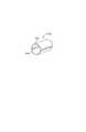
[0040]ここで、図1を参照すると、本発明に係るガイドワイヤ配置装置10の典型的な実施形態が示されている。ガイドワイヤ配置装置10は、基端12と先端14とを有する長尺本体11を含んでいる。長尺本体11は、ガイドカテーテル(図示せず)内に配置されるように寸法付けられており、長尺本体11の長さに沿って略均一な断面を有することが好ましい。 [0040] Referring now to FIG. 1, an exemplary embodiment of a
[0041]長尺本体11の長さに沿って長尺本体11の断面形状を変えることができると考えられる。例えば、長尺本体11は、基端12から先端14へ向けて先細っていてもよい。これは、長尺本体11の剛性を変えることができ、それにより、ガイドワイヤ配置装置10の挿通能力に影響を与える場合がある。また、基端12の外形を更に大きくすると、以下で詳しく説明するように、ガイドワイヤルーメン内へのガイドワイヤの挿入を更に容易にすることができる。 [0041] It is believed that the cross-sectional shape of the
[0042]長尺本体11は、十分なねじれ耐性および挿通能力を与える材料から構成されてもよい。例えば、長尺本体11がナイロンから構成されてもよい。長尺本体11を構成するのに適する他の材料としては、ポリアミド、ペバックス、シリコン、PVC、ポリウレタン、ウレタン、PTFE、ポリエチレン、または、それらの任意の組み合わせが挙げられる。また、長尺本体11の構成中に補強材料が加えられてもよいと考えられる。この場合、補強材料は、所望通りに、長尺本体の全長に沿って或いは長尺本体の一部に沿って配置されてもよい。適切な補強材料の例としては、ワイヤメッシュ、ワイヤブレード、ナイロンブレード、または、当業者に公知の類似の補強技術が挙げられる。 [0042] The
[0043]また、本発明において、長尺本体11は、全体にわたって均一な材料特性を与えるために、単一の材料から単一部材として構成されてもよい。更にまた、長尺本体11は、剛性勾配を与えるために、その長さに沿って変えられる複数の材料から構成されてもよい。長尺本体11の材料は、所望の性能特性を得るように変えることができる。 [0043] Also, in the present invention, the
[0044]図1に示されるように、ガイドワイヤ配置装置10の先端チップ14は、非外傷性チップとして具現化されることが好ましい。チップ14は、非外傷性チップを形成するようにその先端を丸くした縁部を有して形成されることが好ましい。あるいは、装置が曲がりくねった生体構造を通じて挿通されるときにチップが血管壁を傷つけないようにするために、面取りされた縁部が使用されてもよい。先端チップの材料は、低デュロメータから形成されてもよく、あるいは、それを非外傷性にするように可塑化されてもよい。また、図1に示されるように、ガイドワイヤ配置装置10は、チップ14に隣接して配置された放射線不透過性マーカ100を更に含んでいる。マーカ100の様々な実施形態については、更なる図面に関して以下で更に詳しく説明する。 [0044] As shown in FIG. 1, the
[0045]ここで、図1Aを参照すると、図1のA−A線に沿う本発明に係るガイドワイヤ配置装置10の断面図が示されている。図1Aに示されるように、長尺本体11は、それを貫通して延びる少なくとも2つのルーメン20,21を含む固体部材としてほぼ形成されている。ルーメン20,21は、外壁層16と内壁層18とを画定する。本発明の更なる態様において、内壁層18はルーメン20,21を互いから分離する。 [0045] Referring now to FIG. 1A, there is shown a cross-sectional view of the
[0046]再び図1Aを参照すると、図示のように、ガイドワイヤ配置装置10は、外壁層16に形成される切れ目22を更に含んでいる。これらの切れ目22は、ルーメン20,21とガイドワイヤ配置装置10の外部の空間との間を連通させる。本実施形態において、各切れ目22は、他の切れ目の反対側に位置されており、最薄となる外壁層16のポイントに位置付けられている。あるいは、各切れ目22は、最薄となる外壁層16の場所ではなく、他の切れ目に対して対称に或いは非対称に位置されてもよい。 [0046] Referring again to FIG. 1A, as shown, the
[0047]更に、本発明において、各切れ目22は、長尺本体の全長に沿って延びてもよく、あるいは、長尺本体11の基端12に隣接する場所で終端してもよい。各切れ目22は、長尺本体11に沿って先端へと1つの経路をたどって、長尺本体11の先端14で終端してもよい。そうすることで、連続的な切れ目22が形成され、それにより、ガイドワイヤは、長尺本体11の全長にわたってガイドワイヤチャンネル20,21から外壁層16を通過することができる。切れ目は、いずれかのルーメン20,21内に配置されてもよいガイドワイヤの幅よりも小さい幅を有して形成されることが好ましい。 [0047] Further, in the present invention, each cut 22 may extend along the entire length of the elongated body or may terminate at a location adjacent to the proximal end 12 of the
[0048]本発明に係る他の実施形態において、切れ目22は、長尺本体11の基端12で終端してもよく、また、長尺本体11の先端14に近い先端末端部を有していてもよい。 [0048] In other embodiments according to the present invention, the
[0049]切れ目22は、ルーメン20,21内へと外側から切断装置を通すことにより、あるいは、切れ目を形成するようにガイドワイヤチャンネル20,21を通じて切断装置を引き出すことにより、外壁層16に形成されてもよい。 [0049] The
[0050]あるいは、外壁層16の切れ目22は、マンドレルを用いてガイドワイヤチャンネル20,21を支持した後、マンドレルとレーザ源との間に外壁層16を通すことにより形成されてもよい。この場合、レーザ源は、外壁層16を貫くようにレーザビームを方向付け、それにより、切れ目22を形成する。他の実施形態の更なる態様では、例えばこれらに限定されないが、Nd−YAGレーザ、エキシマレーザ、ナノ秒レーザ、フェムト秒レーザ、CO2レーザなど、様々なレーザ源が使用されてもよい。また、レーザは、ウォータージェットなどの適した集束エネルギ源と置き換えられてもよい。 [0050] Alternatively, the
[0051]ここで、図2A〜図2Dを参照すると、前述した本発明に係るガイドワイヤ配置装置10の放射線不透過性マーカ100における様々な実施形態が本発明にしたがって示されている。 [0051] Referring now to FIGS. 2A-2D, various embodiments of the
[0052]ここで、図2Aを参照すると、本発明に係る放射線不透過性マーカの1つの実施形態が示されている。図2Aに示されるように、マーカ100aは円筒形態を有しており、それにより、マーカを長尺本体11の全周と結合するように配置させることができる。言うまでもなく、この形態を用いると、外壁層16の切れ目22が塞がれ、したがって、ガイドワイヤは、ガイドワイヤチャンネル20,21からガイドワイヤ配置装置10の外部の空間へと通過することができない。しかしながら、マーカを軸方向にカットすることによりガイドワイヤをガスチャンネルから抜去することができる。 [0052] Referring now to FIG. 2A, one embodiment of a radiopaque marker according to the present invention is shown. As shown in FIG. 2A, the
[0053]ここで、図2Bを参照すると、本発明に係る放射線不透過性マーカ100bの第2の他の実施形態が示されている。図2Bに示されるように、放射線不透過性マーカ100bはコイル形態として具現化されている。この形態では、マーカを長尺本体11の全周と結合するように配置させることができる。図2Bに示される実施形態に関して前述したように、放射線不透過性マーカ100bも、外壁層16の切れ目22を塞ぐ。しかしながら、マーカを軸方向にカットすることによりガイドワイヤをガスチャンネルから抜去することができる。 [0053] Referring now to FIG. 2B, there is shown a second alternative embodiment of a
[0054]ここで、図2Cを参照すると、本発明に係る放射線不透過性マーカの第3の実施形態が示されている。図2Cに示されるように、放射線不透過性マーカ100cは第1の半体102と第2の半体104とから成っている。この場合、第1および第2の半体は、長尺部材11の曲率半径にほぼ等しい曲率半径を有している。各半体は、長尺部材11の外面の所望の場所に貼り付けられることが好ましい。半体は、組み付けられると、長尺シャフト11の全周を取り囲まず、それにより、切れ目22を塞がない状態のままにしておく。 [0054] Referring now to FIG. 2C, a third embodiment of a radiopaque marker according to the present invention is shown. As shown in FIG. 2C, the
[0055]ここで、図2Dを参照すると、本発明に係る放射線不透過性マーカの第4の他の実施形態が示されている。図2Dに示されるように、放射線不透過性マーカ100dは、少なくとも長手方向部材から形成され、より好ましくは、複数の長手方向部材から形成される。各長手方向部材は、長尺部材11の長手方向軸とほぼ位置合わせされる。長手方向部材は、外壁層16の切れ目22を塞がないように長尺部材と結合させることができ、それにより、ガイドワイヤがガイドワイヤチャンネル20,21から切れ目22を通過することができる。 [0055] Referring now to FIG. 2D, a fourth other embodiment of a radiopaque marker according to the present invention is shown. As shown in FIG. 2D, the
[0056]前述した図2A〜図2Dに示される放射線不透過性マーカは、生体適合性接着剤を用いて長尺シャフトの外面に貼り付けられることが好ましい。この接着剤は、放射線不透過性マーカ100の内面及び/又は長尺本体11の外面に塗布される時間硬化または光硬化シアノアクリレートであってもよい。その結果、マーカ100および長尺本体11を接触した状態に配置することができ、それにより、接着剤を硬化させて、構成要素間を結合させることができる。更に、本実施形態においては、接着剤のビードを放射線不透過性マーカ100の縁部に隣接して配置することができ、その後、接着剤を硬化させることができる。硬化された接着剤ビードは、マーカ100の表面と長尺本体11との間の滑らかな移行部を形成し、それにより、ガイドワイヤ配置装置10が生体構造を通じて挿通されるときに血管に対する損傷が防止される。 [0056] The radiopaque markers shown in FIGS. 2A-2D described above are preferably affixed to the outer surface of the elongate shaft using a biocompatible adhesive. This adhesive may be a time-cured or light-cured cyanoacrylate that is applied to the inner surface of the
[0057]あるいは、放射線不透過性マーカ100は、熱溶着プロセスを使用して長尺シャフトに対して貼り付けられてもよい。このプロセスでは、放射線不透過性マーカ100が長尺本体11と接触して配置され、放射線不透過性マーカに対して熱が加えられる。長尺部材を形成する材料の低い融解温度に起因して、長尺部材が溶けて放射線不透過性マーカ100内およびその周囲に流れる。熱を構成要素から除去することができ、それにより、完成したアセンブリが得られる。また、この実施形態においては、熱を加える前に熱収縮チューブがアセンブリ上にわたって配置されてもよい。熱が加えられた後、熱収縮チューブは、直径が減少して、放射線不透過性マーカ100および長尺本体11の表面と接触する。熱が加えられると、長尺本体11の材料が溶けて熱収縮チューブ内に流れる。溶けた材料は、放射線不透過性マーカ100内およびその周囲に流れるとともに、熱収縮チューブによって与えられる適合性に起因してマーカの縁部に滑らかな移行部をもたらす。マンドレルがルーメン及び/又は切れ目内に配置され、それにより、このプロセス中にルーメンおよび切れ目が原形を保持してもよい。 [0057] Alternatively, the
[0058]本発明の更に他の実施形態では、スウェージングプロセスを使用して放射線不透過性マーカ100を長尺本体11に対して貼り付けるための方法が提供される。この実施形態では、例えば図2Aに示されるようなマーカ要素が利用されてもよい。マーカ要素は連続円周材料形態を有しているため、例えばスウェージングプロセスを使用して径方向の力を加えることにより、材料をより小さい直径へと変形させることができる。したがって、放射線不透過性マーカ100は、長尺本体11上の所望の場所に配置されてもよい。次に、径方向の力が放射線不透過性マーカに対して加えられ、それにより、マーカが変形されて、マーカが長尺部材と干渉接触した状態に配置されてもよい。構成要素間の干渉接触は、マーカを長尺部材に対して固定し、それにより、最終的なアセンブリが得られる。随意的に、スウェージングプロセス中、マンドレルが長尺部材のガイドワイヤチャンネル20,21の一方または全ての内側に配置されてもよい。 [0058] In yet another embodiment of the present invention, a method is provided for applying the
[0059]また、本発明に係る放射線不透過性マーカ100が放射線不透過性インクの形態で具現化されてもよいと考えられる。放射線不透過性インクは、パッド印刷などの公知の印刷方法を使用して長尺本体11の表面に対して加えることができる。必要な場合は、放射線不透過性インク上にわたって保護層が配置されてもよい。この場合、保護層は、硬化可能な接着剤または熱収縮材料から成っていてもよい。また、保護層は、接着剤または熱溶着プロセスによって放射線不透過性インク上に固定されるフィルムであってもよい。 [0059] It is also contemplated that the
[0060]ここで、図3を参照すると、本発明に係るガイドワイヤ配置装置10の先端の部分斜視図が示されている。図3に示されるように、図2Bに示される放射線不透過性マーカがガイドワイヤ配置装置10の先端近傍に配置されて示されている。前述したように、放射線不透過性マーカのこの実施形態は2つの構成要素102,104を含んでおり、各構成要素は半円筒形状を成している。図3に示されるように、これらのマーカ半体はそれぞれ、長尺本体11の外壁層16の切れ目が塞がれないように長尺本体11と結合して配置させることができる。これにより、ガイドワイヤは、ガイドワイヤチャンネル20,21から長尺本体11の外壁層16の切れ目22を通過することができる。 [0060] Referring now to FIG. 3, a partial perspective view of the distal end of the
[0061]ここで、図4を参照すると、本発明に係る代替的な実施形態のガイドワイヤ配置装置の端面図が示されている。図4に示されるように、この代替的な実施形態に係る長尺本体11’はローディングチャンネル200を更に含んでいる。このローディングチャンネル200は、補強マンドレル(図示せず)を挿入するために使用できる。マンドレルは、長尺本体11’を構成するために使用される材料よりも硬質な材料から構成されてもよい。例えば、マンドレルは、ステンレススチール、ニチノール、または、ガラス充填デルリン、または、他の生体適合性材料または複合体であってもよい。より硬質なマンドレルは、より良好なねじれ耐性および挿通能力を与える構造的特性をアセンブリ全体に対して与える。この図のローディングチャンネル200は、長尺本体11’の内壁層18’内の場所に示されているが、更なる実施形態において、ローディングチャンネル200は、長尺本体11によって規定される長手方向軸と同軸でない場所に配置されてもよい。また、長尺本体材料よりも柔軟な補強マンドレルを使用することもできる。複合構造は、依然として、全体にわたって増大または剛性を与えるように作用する。 [0061] Referring now to FIG. 4, an end view of an alternative embodiment guidewire placement device in accordance with the present invention is shown. As shown in FIG. 4, the
[0062]ここで、図5を参照すると、本発明に係るガイドワイヤ配置装置50の更に他の代替実施形態が示されている。図5に示される実施形態によれば、ガイドワイヤ配置装置50は、基端52と先端54とを有する長尺本体51を備えている。ここで、図5Aを参照すると、図5のB−B線に沿う長尺本体51の断面図が示されている。この図によって示されるように、長尺本体51は、先の実施形態で説明されるように、より硬質な材料から形成されるマンドレルを受け入れるように寸法付けられたローディングチャンネル500を含んでいる。また、剛性を与えるため、および、カテーテルチップなどの様々なポイントでマーカとして機能するように、ローディングチャンネル500内に放射線不透過性材料が挿入されてもよい。本実施形態において、長尺本体51は略「S湾曲」形状を有している。この形状の表面は、本発明に係る長尺本体51の内壁層58を規定する。ここで、図6を参照すると、ガイドカテーテル内に配置される図5のガイドワイヤ配置装置が示されている。図6に示されるように、長尺本体51がガイドカテーテル300と結合させて配置されると、ガイドワイヤチャンネル520,521が形成される。ガイドワイヤチャンネル520,521は、長尺本体51の内壁層58とガイドカテーテル300の内面とによって画成される。 [0062] Referring now to FIG. 5, yet another alternative embodiment of a
[0063]また、本発明においては、言うまでもなく、本発明に係るガイドワイヤローディング装置の様々な実施形態に係る長尺本体の外形は、本発明から逸脱することなく、様々な幾何学的形状によって具現化することができる。例えば、ここで、図7A〜図7Bを参照すると、図7Aに示されるように、略「クロス」形状である断面形状を有することができる。更にまた、図7Bに示されるように、略「螺旋」である長尺本体71形状が使用されてもよい。これらの長尺部材形状は、典型例であり、本発明にしたがって利用され得る形状の可能性を限定するように意図されていない。 [0063] Also, in the present invention, it goes without saying that the outer shape of the elongated body according to various embodiments of the guide wire loading device according to the present invention can be changed according to various geometric shapes without departing from the present invention. Can be embodied. For example, referring now to FIGS. 7A-7B, as shown in FIG. 7A, it may have a cross-sectional shape that is generally “cross” shaped. Furthermore, as shown in FIG. 7B, a long main body 71 shape that is substantially “spiral” may be used. These elongate member shapes are exemplary and are not intended to limit the possibilities of shapes that can be utilized in accordance with the present invention.
[0064]また、長尺本体は、前述したようにローディングチャンネルまたは補強マンドレルを含んでいる必要はない。例えば、図7Bに示される本発明の他の実施形態において、長尺本体を螺旋形態で具現化することができる。この場合、図示のように、螺旋形態は、第1のルーメンおよび第2のルーメンを形成する。 [0064] Also, the elongate body need not include a loading channel or reinforcing mandrel as described above. For example, in another embodiment of the present invention shown in FIG. 7B, the elongated body can be embodied in a spiral form. In this case, as shown, the spiral form forms a first lumen and a second lumen.
[0065]また、本発明において、長尺本体の表面は、潤滑性を高めるように構成されるコーティングを含んでいてもよい。この実施形態の更なる態様では、摩擦を減少させ及び/又は潤滑性を高めるために、合成潤滑油または天然潤滑油が長尺本体の外面に塗布されてもよく及び/又はここで説明したルーメン内に塗布されてもよい。他の実施形態では、これらの表面が親水性コーティングを用いて処理されてもよい。 [0065] Also in the present invention, the surface of the elongate body may include a coating configured to enhance lubricity. In a further aspect of this embodiment, synthetic or natural lubricants may be applied to the outer surface of the elongated body and / or the lumens described herein to reduce friction and / or increase lubricity. It may be applied inside. In other embodiments, these surfaces may be treated with a hydrophilic coating.
[0066]本発明に係るガイドワイヤ配置装置は、脈管系の血管枝内へ少なくとも1つのガイドワイヤを配置するために利用されてもよい。血管枝の例は二股冠状血管である。本発明のガイドワイヤ配置装置はガイドカテーテルと共に利用されることが好ましい。ガイドカテーテルは、患者の脈管構造内に予め配置しておく。その後、ガイドワイヤ配置装置がガイドカテーテル内に配置されて所望の位置へと前進される。ガイドワイヤ配置装置の位置決めは、蛍光透視下でガイドワイヤ配置装置の先端に隣接して配置される放射線不透過性マーカを見ることによって検証されてもよい。 [0066] A guidewire placement device according to the present invention may be utilized to place at least one guidewire within a vascular branch of a vascular system. An example of a vascular branch is a bifurcated coronary blood vessel. The guidewire placement device of the present invention is preferably used with a guide catheter. The guide catheter is previously placed in the patient's vasculature. Thereafter, a guidewire placement device is placed in the guide catheter and advanced to the desired position. The positioning of the guidewire placement device may be verified by looking at a radiopaque marker placed adjacent to the tip of the guidewire placement device under fluoroscopy.
[0067]ガイドワイヤ配置装置を所望の位置に配置した後、第1のガイドワイヤをガイドワイヤ配置装置の一方のルーメン内へ挿入して第1の冠動脈二股分岐内へ押し進めることができる。その後、第2のガイドワイヤを第2のルーメン内に配置して第2の冠動脈二股分岐内へ押し進めることができる。各ガイドワイヤが別個のガイドワイヤチャンネルを通じて挿通されるため、ガイドワイヤが内壁層18によって装置の全長にわたって分離された状態に保たれることは言うまでもない。したがって、さもなければ起こり得るガイドワイヤの絡み、ねじれ、あるいは、結節が生じる可能性がない。 [0067] After placing the guidewire placement device in the desired location, the first guidewire can be inserted into one lumen of the guidewire placement device and pushed into the first bifurcated bifurcation of the coronary artery. Thereafter, a second guidewire can be placed in the second lumen and pushed into the second bifurcated coronary artery. Of course, since each guide wire is threaded through a separate guide wire channel, the guide wire is kept separated by the
[0068]ガイドワイヤを配置した後、ガイドワイヤをガイドワイヤ配置装置のルーメンから除去することができる。ガイドワイヤは、異なる方法を利用して除去されてもよい。1つのそのような方法は、各ガイドワイヤが、ガイドワイヤ配置装置10の外部の空間へ向けて、長尺本体11の外壁層16に形成された切れ目22を通過できるようにすることである。このようにして除去を始めるため、ガイドワイヤは、ガイドワイヤ配置装置の基端に形成された切れ目を通じて除去されて、各ガイドワイヤがそれらの対応するルーメンを離れるまで長尺部材の長さに沿って伝搬されてもよい。「伝搬」は、配置装置の外部のガイドワイヤ上にわたって第2の装置を通すことによって、あるいは、ガイドワイヤとガイドワイヤ配置装置の外面との間の表面を先端側へ通すことによって容易にされてもよい。 [0068] After placing the guidewire, the guidewire can be removed from the lumen of the guidewire placement device. The guide wire may be removed using different methods. One such method is to allow each guide wire to pass through a
[0069]ガイドワイヤをそれらの対応するルーメンから除去する他の方法は、各ガイドワイヤの位置を保ちつつガイドワイヤ配置装置をガイドカテーテルから除去することである。これは、長尺本体11の先端14がもはやガイドワイヤと結合されなくなるまでガイドワイヤローディング装置に対して軸方向の力を基端方向に加えることによって達成されてもよい。随意的に、ガイドワイヤは、軸方向の力を加えている間、ガイドカテーテルの基端に固定され、それにより、冠状二股血管内でのガイドワイヤの位置が維持される。 [0069] Another way to remove guidewires from their corresponding lumens is to remove the guidewire placement device from the guide catheter while maintaining the position of each guidewire. This may be accomplished by applying an axial force to the guide wire loading device in the proximal direction until the
[0070]この方法により、2つのガイドワイヤ間のねじれ或いはもつれを最小限に抑えつつ、2つのガイドワイヤが冠状二股血管の分岐内に配置される。したがって、これらに限定されないがProvisional T技術、Culottes技術、および、Crush技術などのインターベンション技術、また、多くの実施形態が本発明にしたがって可能であるという趣旨で、「キャッチオール」パラグラフなどを実行するためにガイドワイヤを使用できる。 [0070] This method places the two guidewires within the coronary bifurcation bifurcation while minimizing twisting or entanglement between the two guidewires. Therefore, although not limited to these, interventional technologies such as, but not limited to, Provisional T technology, Clottes technology, and Crush technology, and “catch-all” paragraphs, etc. are implemented in the sense that many embodiments are possible in accordance with the present invention. A guide wire can be used to do this.
[0071]本発明の特定の実施形態を図示して説明してきたが、当業者に明らかなように、本発明から逸脱することなくその広範な態様で変更および改良を成すことができる。したがって、添付の請求項は、それらの範囲内に、本発明の精神および範囲内に入るそのような変更および改良の全てを包含するものである。 [0071] While particular embodiments of the present invention have been illustrated and described, it will be apparent to those skilled in the art that changes and modifications can be made in its broader aspects without departing from the invention. Accordingly, the appended claims are intended to encompass within their scope all such changes and modifications as fall within the spirit and scope of this invention.
Claims (10)
Translated fromJapanese前記先端に形成されるチップと、
第1のガイドワイヤを受けるため第1のルーメンであって、前記内壁層によって部分的に画成されるとともに前記長尺本体の外壁層によって更に画成され、前記長尺本体の長さに沿って延びる第1のルーメンと、
前記外壁層に形成され、前記第1のルーメンに結合された第1の切れ目と、
第2のガイドワイヤを受けるための第2のルーメンであって、前記内壁層によって部分的に画成されるとともに前記長尺本体の外壁層によって更に画成され、前記長尺本体の長さに沿って延びる第2のルーメンと、
前記外壁層に形成され、前記第2のルーメンに結合された第2の切れ目と、
を備え、
前記第1の切れ目および前記第2の切れ目のうちの一方が、前記先端で始まるとともに、前記長尺本体の長さ全体に沿って延びるか前記基端より手前で終端する、ガイドワイヤ配置装置。An elongated body having a proximal end and a distal end, and an inner wall layerand an outer wall layer ;
A chip formed at the tip;
A first lumen for receiving a first guidewire,is further defined by an outer wall layer of Rutotomoni the elongate body partially defined by said inner wall layer, along the length of the elongated body A first lumen extending
A first cut formed in the outer wall layer and coupled to the first lumen;
A second lumen for receiving a second guide wire, partially defined by the inner wall layer and further defined by an outer wall layer of the elongate body, the length of the elongate body A second lumen extending along;
A second cut formed in the outer wall layer and coupled to the second lumen;
Equipped witha,
One of the first cut and the second cut starts at the tip and extends along the entire length of the long main body or ends before the base end .
Applications Claiming Priority (3)
| Application Number | Priority Date | Filing Date | Title |
|---|---|---|---|
| US79378706P | 2006-04-21 | 2006-04-21 | |
| US60/793,787 | 2006-04-21 | ||
| PCT/US2007/009888WO2007124161A1 (en) | 2006-04-21 | 2007-04-23 | Guidewire placement device |
Publications (3)
| Publication Number | Publication Date |
|---|---|
| JP2009534110A JP2009534110A (en) | 2009-09-24 |
| JP2009534110A5 JP2009534110A5 (en) | 2010-06-17 |
| JP5153767B2true JP5153767B2 (en) | 2013-02-27 |
Family
ID=38511402
Family Applications (1)
| Application Number | Title | Priority Date | Filing Date |
|---|---|---|---|
| JP2009506640AExpired - Fee RelatedJP5153767B2 (en) | 2006-04-21 | 2007-04-23 | Guide wire placement device |
Country Status (5)
| Country | Link |
|---|---|
| US (1) | US20080027411A1 (en) |
| EP (1) | EP2015826B1 (en) |
| JP (1) | JP5153767B2 (en) |
| AT (1) | ATE531417T1 (en) |
| WO (1) | WO2007124161A1 (en) |
Families Citing this family (12)
| Publication number | Priority date | Publication date | Assignee | Title |
|---|---|---|---|---|
| MX344665B (en)* | 2006-10-18 | 2017-01-04 | Medical Components Inc | Venous access port assembly with radiopaque indicia. |
| WO2010070684A1 (en)* | 2008-12-18 | 2010-06-24 | Invatec S.P.A. | Catheter, catheter assembly and relevant method |
| JP5206542B2 (en)* | 2009-03-27 | 2013-06-12 | ニプロ株式会社 | Guide wire entanglement release device |
| EP2646099B1 (en)* | 2010-12-01 | 2015-04-08 | Abiomed, Inc. | Radiopaque cannula marker |
| JP5810554B2 (en) | 2011-02-28 | 2015-11-11 | ソニー株式会社 | Electronic device, display method, and program |
| US9278198B2 (en)* | 2011-12-28 | 2016-03-08 | Boston Scientific Scimed, Inc. | Biliary access catheter system and methods for accessing the biliary tree |
| US9364208B2 (en)* | 2014-03-18 | 2016-06-14 | King Abdullah International Medical Research Center | Medical material delivery device |
| US20160114130A1 (en)* | 2014-10-24 | 2016-04-28 | Boston Scientific Scimed, Inc. | Medical device including a marker element |
| US10737008B2 (en)* | 2015-08-17 | 2020-08-11 | Abiomed, Inc. | Dual lumen sheath for arterial access |
| CN116407729B (en)* | 2021-12-29 | 2025-06-03 | 杭州诺沁医疗器械有限公司 | Adjustable sheath tube |
| CN116549171A (en)* | 2023-07-12 | 2023-08-08 | 苏州美创医疗科技有限公司 | Artificial blood vessel |
| CN119868767B (en)* | 2025-03-24 | 2025-06-10 | 万漉医疗科技(江苏)有限公司 | Guide wire with vascular stent |
Family Cites Families (21)
| Publication number | Priority date | Publication date | Assignee | Title |
|---|---|---|---|---|
| JPS59228205A (en)* | 1983-06-09 | 1984-12-21 | Sumitomo Electric Ind Ltd | Grooved optical transmission line |
| US4601713A (en)* | 1985-06-11 | 1986-07-22 | Genus Catheter Technologies, Inc. | Variable diameter catheter |
| NL8600338A (en)* | 1986-02-11 | 1987-09-01 | Louis Johannes Karel Jozef Rey | CATHETER PROVIDED WITH POSITIONERS. |
| US5025778A (en)* | 1990-03-26 | 1991-06-25 | Opielab, Inc. | Endoscope with potential channels and method of using the same |
| WO1992017236A1 (en)* | 1991-04-05 | 1992-10-15 | Boston Scientific Corporation | Adjustably stiffenable convertible catheter assembly |
| US5456680A (en)* | 1993-09-14 | 1995-10-10 | Spectranetics Corp | Fiber optic catheter with shortened guide wire lumen |
| US5542937A (en)* | 1994-06-24 | 1996-08-06 | Target Therapeutics, Inc. | Multilumen extruded catheter |
| US6458076B1 (en)* | 2000-02-01 | 2002-10-01 | 5 Star Medical | Multi-lumen medical device |
| JP2001224692A (en)* | 2000-02-18 | 2001-08-21 | Asahi Optical Co Ltd | Endoscope catheter |
| SI1255506T1 (en)* | 2000-02-18 | 2004-02-29 | E.V.R. Endovascular Researches S.A. | Endolumenal device for delivering and deploying an endolumenal expandable prosthesis |
| DE10009756B4 (en)* | 2000-03-01 | 2004-03-25 | Ems-Chemie Ag | Colorless, highly transparent polyamide blends with improved stress crack resistance |
| EP1267984B1 (en)* | 2000-03-21 | 2005-11-09 | Cook Incorporated | Introducer sheath |
| WO2001070299A2 (en)* | 2000-03-22 | 2001-09-27 | Advanced Stent Technologies, L.L.C. | Guidewire introducer sheath |
| US7238168B2 (en)* | 2000-06-02 | 2007-07-03 | Avantec Vascular Corporation | Exchangeable catheter |
| US6569180B1 (en)* | 2000-06-02 | 2003-05-27 | Avantec Vascular Corporation | Catheter having exchangeable balloon |
| AU2002350164A1 (en)* | 2001-11-08 | 2003-05-19 | William D. Hare | Rapid exchange catheter with stent deployment, therapeutic infusion, and lesion sampling features |
| US7534223B2 (en) | 2002-10-08 | 2009-05-19 | Boston Scientific Scimed, Inc. | Catheter with formed guide wire ramp |
| US8016752B2 (en)* | 2003-01-17 | 2011-09-13 | Gore Enterprise Holdings, Inc. | Puncturable catheter |
| US7815565B2 (en)* | 2003-05-16 | 2010-10-19 | Ethicon Endo-Surgery, Inc. | Endcap for use with an endoscope |
| US7762949B2 (en)* | 2003-10-16 | 2010-07-27 | Granit Medical Innovation, Llc | Endoscope with open channels |
| US20070021648A1 (en)* | 2005-06-29 | 2007-01-25 | Jay Lenker | Transluminal sheath hub |
- 2007
- 2007-04-23EPEP07776058Apatent/EP2015826B1/ennot_activeCeased
- 2007-04-23JPJP2009506640Apatent/JP5153767B2/ennot_activeExpired - Fee Related
- 2007-04-23ATAT07776058Tpatent/ATE531417T1/enactive
- 2007-04-23WOPCT/US2007/009888patent/WO2007124161A1/enactiveApplication Filing
- 2007-04-23USUS11/739,050patent/US20080027411A1/ennot_activeAbandoned
Also Published As
| Publication number | Publication date |
|---|---|
| ATE531417T1 (en) | 2011-11-15 |
| WO2007124161A1 (en) | 2007-11-01 |
| JP2009534110A (en) | 2009-09-24 |
| EP2015826A1 (en) | 2009-01-21 |
| EP2015826B1 (en) | 2011-11-02 |
| US20080027411A1 (en) | 2008-01-31 |
Similar Documents
| Publication | Publication Date | Title |
|---|---|---|
| JP5153767B2 (en) | Guide wire placement device | |
| US12042411B2 (en) | Methods and apparatus for luminal stenting | |
| JP4874502B2 (en) | Apparatus for delivering an endoluminal prosthesis and methods of making and using the same | |
| US8623067B2 (en) | Methods and apparatus for luminal stenting | |
| US10449029B2 (en) | Retrieval catheter | |
| US11666465B2 (en) | Vascular stenting for aneurysms | |
| US7131981B2 (en) | Device and method for converting a balloon catheter into a cutting balloon catheter | |
| US8636707B2 (en) | Bifurcated stent delivery system | |
| JP2002102357A (en) | Feeder for self-expanding stent | |
| US20070288081A1 (en) | Stent delivery system having a stent stopper | |
| EP1853204B1 (en) | Stent delivery and guidewire guidance system with multiple guidewires | |
| US20240350287A1 (en) | Methods and apparatus for luminal stenting |
Legal Events
| Date | Code | Title | Description |
|---|---|---|---|
| A521 | Request for written amendment filed | Free format text:JAPANESE INTERMEDIATE CODE: A523 Effective date:20100422 | |
| A621 | Written request for application examination | Free format text:JAPANESE INTERMEDIATE CODE: A621 Effective date:20100422 | |
| A977 | Report on retrieval | Free format text:JAPANESE INTERMEDIATE CODE: A971007 Effective date:20111222 | |
| A131 | Notification of reasons for refusal | Free format text:JAPANESE INTERMEDIATE CODE: A131 Effective date:20120110 | |
| A601 | Written request for extension of time | Free format text:JAPANESE INTERMEDIATE CODE: A601 Effective date:20120410 | |
| A602 | Written permission of extension of time | Free format text:JAPANESE INTERMEDIATE CODE: A602 Effective date:20120417 | |
| A521 | Request for written amendment filed | Free format text:JAPANESE INTERMEDIATE CODE: A523 Effective date:20120509 | |
| TRDD | Decision of grant or rejection written | ||
| A01 | Written decision to grant a patent or to grant a registration (utility model) | Free format text:JAPANESE INTERMEDIATE CODE: A01 Effective date:20121106 | |
| A61 | First payment of annual fees (during grant procedure) | Free format text:JAPANESE INTERMEDIATE CODE: A61 Effective date:20121204 | |
| FPAY | Renewal fee payment (event date is renewal date of database) | Free format text:PAYMENT UNTIL: 20151214 Year of fee payment:3 | |
| R150 | Certificate of patent or registration of utility model | Ref document number:5153767 Country of ref document:JP Free format text:JAPANESE INTERMEDIATE CODE: R150 Free format text:JAPANESE INTERMEDIATE CODE: R150 | |
| R250 | Receipt of annual fees | Free format text:JAPANESE INTERMEDIATE CODE: R250 | |
| R250 | Receipt of annual fees | Free format text:JAPANESE INTERMEDIATE CODE: R250 | |
| R250 | Receipt of annual fees | Free format text:JAPANESE INTERMEDIATE CODE: R250 | |
| R250 | Receipt of annual fees | Free format text:JAPANESE INTERMEDIATE CODE: R250 | |
| LAPS | Cancellation because of no payment of annual fees |