JP5153182B2 - Display device - Google Patents
Display deviceDownload PDFInfo
- Publication number
- JP5153182B2 JP5153182B2JP2007086478AJP2007086478AJP5153182B2JP 5153182 B2JP5153182 B2JP 5153182B2JP 2007086478 AJP2007086478 AJP 2007086478AJP 2007086478 AJP2007086478 AJP 2007086478AJP 5153182 B2JP5153182 B2JP 5153182B2
- Authority
- JP
- Japan
- Prior art keywords
- light
- color
- light intensity
- display device
- ambient light
- Prior art date
- Legal status (The legal status is an assumption and is not a legal conclusion. Google has not performed a legal analysis and makes no representation as to the accuracy of the status listed.)
- Expired - Fee Related
Links
Images


Landscapes
- Devices For Indicating Variable Information By Combining Individual Elements (AREA)
- Liquid Crystal (AREA)
- Electroluminescent Light Sources (AREA)
Description
Translated fromJapanese本発明は光強度センサを有する表示装置に関する。 The present invention relates to a display device having a light intensity sensor.
近年、携帯電話やミュージックプレイヤーなど小型フラットパネルディスプレイを備えた携帯機器の普及が進みつつある。このような携帯機器は真夏の直射日光下など非常に環境照度の大きい場所で使われることがあり、搭載されるフラットパネルディスプレイにも高輝度で画像を表示することが求められる。一方、室内の利用時においてはこのような高輝度での表示は必要がない。このため低消費電力等の観点から周囲の環境照度に応じてディスプレイの輝度を調整することを特徴とした表示装置が特許文献1において開示されている。 In recent years, mobile devices having a small flat panel display such as a mobile phone and a music player are becoming popular. Such portable devices are sometimes used in places with very large environmental illuminance, such as under direct sunlight in midsummer, and it is required to display images with high brightness on the mounted flat panel display. On the other hand, such high-intensity display is not necessary for indoor use. For this reason, Patent Document 1 discloses a display device that adjusts the brightness of a display in accordance with ambient environmental illuminance from the viewpoint of low power consumption and the like.
屋外での利用が想定される携帯機器では、外光による画質への妨害を防ぐために反射防止膜を最表面に施すことがあり得る。このような反射防止膜は人間の視感度がもっとも高い緑に相当する波長550nm付近の光の反射を抑えるべく設計されることが多く、それ以外の波長の光は反射を防止できないことがあり得る。 In a portable device assumed to be used outdoors, an antireflection film may be provided on the outermost surface in order to prevent interference with image quality due to external light. Such an antireflection film is often designed to suppress reflection of light in the vicinity of a wavelength of 550 nm corresponding to green, which has the highest human visibility, and light of other wavelengths may not be able to prevent reflection. .
そのため、表示画像に反射光の青や紫の成分が重畳されることがあり、表示品位の低下を生じることがあり得る。 Therefore, the blue or purple component of the reflected light may be superimposed on the display image, and display quality may be deteriorated.
また屋外では外光は照度だけでなく色味も変化する。例えば正午近くの太陽光は昼光色や昼白色と呼ばれる色味であるが、夕方は赤みを帯びた光となる。このような場所でディスプレイが表示する白色を観察した場合、人間の視覚は周囲光の色温度に影響される。 In addition, outside light changes not only in illuminance but also in color. For example, sunlight near noon has a color called daylight color or daytime white, but it becomes reddish in the evening. When the white color displayed on the display is observed in such a place, human vision is affected by the color temperature of ambient light.
そのため、ディスプレイが同じ白色表示を行ったとして周囲光の状況の違いによって不自然な色合いの白色表示として感じる場合があり得る。 Therefore, even if the display performs the same white display, it may be felt as a white display with an unnatural color due to a difference in ambient light conditions.
本発明はこのような課題を鑑みて行われるものであって、その目的は良好な色味を実現できる表示装置を提供することにある。 The present invention has been made in view of such problems, and an object thereof is to provide a display device capable of realizing a good color.
上記背景技術の課題を解決するための手段として、請求項1に記載した発明に係る表示装置は、
有機EL素子が表示素子として用いられる表示パネルと、
環境光の赤色成分、緑色成分、青色成分の各色成分の光強度を検出する光強度センサと、を備え、
前記光強度センサが検出した前記環境光の各色成分の光強度を基に、前記表示パネルに入力される各色成分の映像信号が独立に制御され、
前記各色成分の映像信号は、前記表示パネルが白色を表示するときの色温度が、前記表示パネルの表面での前記環境光の反射光の色調を打ち消し、かつ、前記環境光の色温度よりも2500Kから3500K高くなるように制御されることを特徴とする。As a means for solving the problems of the background art, a display device according to the invention described in claim 1 includes:
A display panel in which an organic EL element is used as a display element;
A light intensity sensor that detects the light intensity of each color component of the environmental light red component, green component, and blue component,
Based on the light intensity of each color component of the ambient light detected by the light intensity sensor, the video signal of each color component input to the display panel is independently controlled,
The video signal of each color component is such that the color temperature when the display panel displays whitecolor cancels the color tone of the reflected light of the ambient light on the surface of the display panel, and is lower than the color temperature of the ambient light. It is controlled to increase from 2500K to 3500K.
本発明に係る表示装置は、良好な色味を実現できる。 The display device according to the present invention can realize a good color.
表示装置の表面における外光の反射に関する波長特性は、表示装置の表面の材質や表面処理により定まる。そのため、外光の分光特性を何らかの形で検出できれば、反射光の分光特性は算出することができる。 The wavelength characteristics related to the reflection of external light on the surface of the display device are determined by the material and surface treatment of the surface of the display device. Therefore, if the spectral characteristic of external light can be detected in some form, the spectral characteristic of reflected light can be calculated.
本発明は、この知見に基づきなされたものである。 The present invention has been made based on this finding.
以下、本発明を実施するための最良の形態について説明する。 Hereinafter, the best mode for carrying out the present invention will be described.
<第1の実施形態>
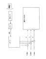
本実施形態の表示装置は、自発光型の有機EL素子を表示素子として基板上に形成されて成る表示装置である。<First Embodiment>
The display device of this embodiment is a display device formed on a substrate using a self-luminous organic EL element as a display element.
この表示装置は、図1に示すように、環境光の光強度を検出するR(赤色)G(緑色)B(青色)の各色それぞれの光強度センサを備えており、前記光強度センサが検出した情報を基に、複数の色信号が独立に制御される構成とされている。 As shown in FIG. 1, this display device includes light intensity sensors for each color of R (red), G (green), and B (blue) that detect the light intensity of ambient light, and the light intensity sensor detects the light intensity sensor. The plurality of color signals are independently controlled based on the information.
具体的に云うと、R光強度センサ1は環境光の赤色成分の光強度に応じたレベルの信号を出力し、この信号はA/D変換機7により赤色信号Rin4に変換されLUT9に出力される。G光強度センサ2及びB光強度センサ3においても同様にそれぞれ緑色信号Gin5及び青色信号Bin6がLUT9に出力される。 More specifically, the R light intensity sensor 1 outputs a signal having a level corresponding to the light intensity of the red component of the ambient light. This signal is converted into a red signal Rin4 by the A /
LUT9に出力された情報は、前記LUT9で以下のように処理される。 Information output to the
上記のRGBの各色の色信号は、各々の色成分の強度を示すものであり、これを以下の<数1>によってCIE 1931表色系にて定義されるXYZ表色系に変換する。 The color signals of the above RGB colors indicate the intensity of each color component, and are converted into the XYZ color system defined in the CIE 1931 color system by the following <Equation 1>.

なお、<数1>中のa11からa33までの各係数は、R光強度センサ1、G光強度センサ2、B光強度センサ3の分光特性に応じて適切に設定すればよい。 In addition, each coefficient from a11 to a33 in <Equation 1> may be set appropriately according to the spectral characteristics of the R light intensity sensor 1, the G light intensity sensor 2, and the B light intensity sensor 3.
次に、得られたXYZの値を用いて、<数2>により色度座標xyzを求める。 Next, using the obtained XYZ values, chromaticity coordinates xyz are obtained by <Equation 2>.
さらに、表示パネル8の表面反射率をrとし、<数1>のXYZの値を用いて、<数3>により表示パネル8表面での環境光の反射光X’Y’Z’の値を求める。 Further, r is the surface reflectance of the display panel 8, and the value of XYZ in <Equation 1> is used, and the value of the reflected light X'Y'Z 'of ambient light on the surface of the display panel 8 is obtained from <Equation 3>. Ask.
この表面反射による妨害を打ち消すように、RGB映像信号の変換係数である変換関数fr(K)、fg(K)、fb(K)を設定する。Conversion functions fr (K), fg (K), and fb (K), which are conversion coefficients of the RGB video signal, are set so as to cancel the interference caused by the surface reflection.
LUT9において設定された変換関数fr(K)、fg(K)、fb(K)を、表示パネル8に電源を供給する電源装置に出力し、表示パネル8に入力されるRGB映像信号Rvideo、Gvideo、Bvideoを変調する。The conversion functions fr (K), fg (K), and fb (K) set in the
すなわち、RGB映像信号であるRvideo、Gvideo、Bvideoを、変換関数fr(K)、fg(K)、fb(K)を用いて、<数4>によりそれぞれR’video、G’video、B’videoに変換する。In other words, Rvideo, Gvideo, and Bvideo, which are RGB video signals, are converted into R′video and G′video by <
この変換関数fr(K)、fg(K)、fb(K)は、上述したように表面反射による妨害を打ち消すように設定されている。つまり、各色の光強度センサ1〜3が検出した光強度により算出された表示パネル8表面での反射光の色調を打ち消すように、白色表示時の色温度が制御されている。そのため、外光による反射光が存在する場合でも本来表示するべき色味で表示することができる。The conversion functions fr (K), fg (K), and fb (K) are set so as to cancel the interference caused by the surface reflection as described above. That is, the color temperature at the time of white display is controlled so as to cancel the color tone of the reflected light on the surface of the display panel 8 calculated by the light intensity detected by the light intensity sensors 1 to 3 of each color. Therefore, even when there is reflected light due to external light, it is possible to display with a color that should originally be displayed.
<第2の実施形態>
本実施形態の表示装置は、複数の色の光源(図示せず)を内蔵したバックライト10を備えた背面発光型の表示装置である。<Second Embodiment>
The display device according to the present embodiment is a back-emitting type display device including a backlight 10 incorporating a plurality of color light sources (not shown).
この表示装置は、図2に示すように、環境光の光強度を検出するRGBの各色それぞれの光強度センサを備えており、前記光強度センサが検出した情報を基に複数の色の光源の光強度が独立に変調される構成とされている。 As shown in FIG. 2, the display device includes light intensity sensors for each of the RGB colors that detect the light intensity of the ambient light. Based on the information detected by the light intensity sensor, the display device includes a plurality of light source colors. The light intensity is modulated independently.
具体的に云うと、表示装置の表示パネル8とバックライト10とは積層されており、表示パネル8にはRGB映像信号であるRvideo、Gvideo、Bvideoが入力され、対応した画像が表示される。 Specifically, the display panel 8 and the backlight 10 of the display device are stacked, and RGB video signals Rvideo, Gvideo, and Bvideo are input to the display panel 8 and corresponding images are displayed.
バックライト10には、内部にRGB各色に応じた光源がそれぞれ内蔵されており、各光源の強度を変えることでバックライト10の色温度を変化させることができる。 The backlight 10 includes light sources corresponding to RGB colors therein, and the color temperature of the backlight 10 can be changed by changing the intensity of each light source.
各光源の強度は、例えばLED光源を用いた場合は電流変調によって変化させることができる。そこで、本実施形態の表示装置は、上記第1の実施形態と同様に、LUT9において設定された変換関数fr(K)、fg(K)、fb(K)を、バックライト10に電源を供給する電源装置に出力する。そして、バックライト10のRGB各光源に対応した電源電流11、12、13の電流量を環境光の色温度に応じて変調し、バックライト10の色温度を調整する。For example, when an LED light source is used, the intensity of each light source can be changed by current modulation. In view of this, the display device according to the present embodiment applies the conversion functions fr (K), fg (K), and fb (K) set in the
これにより、バックライト10中の光源より射出した光は表示パネル8により変調され、本来表示するべき色味で表示することができる。 Thereby, the light emitted from the light source in the backlight 10 is modulated by the display panel 8 and can be displayed in a color to be originally displayed.
<第3の実施形態>
上記第1、第2の実施形態は、様々な環境光に対応するべくRGB各色独立した光強度センサを備えた表示装置について説明した。しかし、例えば屋外で利用するのは主に日中になるなど、利用環境がある程度想定でき、環境光の波長特性を仮定できる場合には、図3に示すように想定される環境光に応じた波長特性をもつ光強度センサを一つだけ用い、構造を簡略化してもよい。つまり、光強度センサを少なくとも一つ備えていればよい。<Third Embodiment>
In the first and second embodiments described above, the display device provided with the light intensity sensors independent of each color of RGB to cope with various environmental lights has been described. However, if the environment of use can be assumed to some extent, for example, it is mainly used during the daytime outdoors, and the wavelength characteristics of the ambient light can be assumed, it depends on the assumed ambient light as shown in FIG. The structure may be simplified by using only one light intensity sensor having wavelength characteristics. That is, it is sufficient to provide at least one light intensity sensor.
<第4の実施形態>
上記第1〜第3の実施形態は、外光による反射光を算出するために光強度センサ及びA/D変換機を備えているが、この構成をそのまま用いて外光の色温度を算出することができる。つまり、光強度センサが検出した環境光のそれぞれの色の光強度を基に前記環境光の色調を算出し、算出された環境光の色調に応じて白色表示時の色温度を制御する。<Fourth Embodiment>
The first to third embodiments include the light intensity sensor and the A / D converter for calculating the reflected light due to the external light. The color temperature of the external light is calculated using this configuration as it is. be able to. That is, the color tone of the environmental light is calculated based on the light intensity of each color of the environmental light detected by the light intensity sensor, and the color temperature at the time of white display is controlled according to the calculated color tone of the environmental light.
具体的に云うと、上記<数2>により得られたxyz値と色温度との関係は「色彩工学」(太田登:1993, 東京大学出版会)に例示されているように1対1に対応するので、光強度センサにより環境光の色温度Kを算出する。 Specifically, the relationship between the xyz value obtained by the above <Equation 2> and the color temperature is 1: 1 as illustrated in “Color Engineering” (Noboru Ota: 1993, University of Tokyo Press). Therefore, the color temperature K of the ambient light is calculated by the light intensity sensor.
次に、RGB映像信号であるRvideo、Gvideo、Bvideoを、上記環境光の色温度Kから導かれた変換関数fr(K)、fg(K)、fb(K)を用いて、<数3>によりそれぞれR’video、G’video、B’videoに変換する。変換関数fr(K)、fg(K)、fb(K)は、Rvideo、Gvideo、Bvideoが最大値をとった際に、表示パネル8表面の白色表示の色温度K’が検出された環境光の色温度Kよりも2500Kから3500K程度高くなるよう設定する。人間の視覚は環境光の色温度により白色表示の感じ方が変化するが、環境光の色温度に対して2500Kから3500K高い色温度での白色表示を観察した場合に良好な白色表示に感じる場合が多いからである。なお、室内での消費電力を抑制するために、低照度の環境では表示輝度を抑制した、変換関数fr(K)、fg(K)、fb(K)を設定してもよい。Next, Rvideo, Gvideo, and Bvideo, which are RGB video signals, are converted using the conversion functions fr (K), fg (K), and fb (K) derived from the color temperature K of the ambient light to < Conversion into R'video, G'video, and B'video, respectively, is made using Equation 3>. The conversion functions fr (K), fg (K), and fb (K) detect the color temperature K ′ of white display on the surface of the display panel 8 when Rvideo, Gvideo, and Bvideo have the maximum values. It is set to be higher than the color temperature K of ambient light by about 2500K to 3500K. Human vision changes how white display is perceived depending on the color temperature of ambient light, but when the white display is observed at a color temperature 2500 to 3500K higher than the color temperature of ambient light, it feels good white display Because there are many. In order to suppress power consumption in the room, conversion functions fr (K), fg (K), and fb (K) that suppress display luminance in a low illuminance environment may be set.
次に、想定される全ての環境光のRGB色信号4、5、6の組み合わせに対して変換係数fr(K)、fg(K)、fb(K)の値を算出し、LUT9内のメモリ(図示せず)に保存する。これは出荷前に予め演算しておくことで実際の回路を簡略化するためである。若しくは、ある特定の環境光のRGB値に応じた計算値の組み合わせを複数用意し、LUT9内に設けられた演算器により他の組み合わせを補間により生成してもよい。Next, the values of the conversion coefficients fr (K), fg (K), fb (K) are calculated for all possible combinations of
なお、上記第1〜第4の実施形態の表示装置の表面に反射防止膜を備えていると、より好ましい。 It is more preferable that an antireflection film is provided on the surface of the display device of the first to fourth embodiments.
1 R光強度センサ
2 G光強度センサ
3 B光強度センサ
4 赤色信号Rin
5 緑色信号Gin
6 青色信号Bin
7 A/D変換機
8 表示パネル
9 LUT(ルックアップテーブル)
10 バックライト
11 R電源電流
12 G電源電流
13 B電源電流1 R light intensity sensor 2 G light intensity sensor 3 B
5 Green signal Gin
6 Blue signal Bin
7 A / D converter 8
10 Backlight 11 R Power supply current 12 G Power supply current 13 B Power supply current
Claims (4)
Translated fromJapanese環境光の赤色成分、緑色成分、青色成分の各色成分の光強度を検出する光強度センサと、を備え、
前記光強度センサが検出した前記環境光の各色成分の光強度を基に、前記表示パネルに入力される各色成分の映像信号が独立に制御され、
前記各色成分の映像信号は、前記表示パネルが白色を表示するときの色温度が、前記表示パネルの表面での前記環境光の反射光の色調を打ち消し、かつ、前記環境光の色温度よりも2500Kから3500K高くなるように制御されることを特徴とする表示装置。A display panel in which an organic EL element is used as a display element;
A light intensity sensor that detects the light intensity of each color component of the environmental light red component, green component, and blue component,
Based on the light intensity of each color component of the ambient light detected by the light intensity sensor, the video signal of each color component input to the display panel is independently controlled,
The video signal of each color component is such that the color temperature when the display panel displays whitecolor cancels the color tone of the reflected light of the ambient light on the surface of the display panel, and is lower than the color temperature of the ambient light. A display device controlled to increase from 2500K to 3500K.
算出された前記環境光の色調を基に、前記環境光の色温度が算出されることを特徴とする請求項1に記載の表示装置。Based on the light intensity of each color component of the ambient light detected by the light intensity sensor, the color tone of the ambient light is calculated,
The display device according to claim 1, wherein a color temperature of the ambient light is calculated based on the calculated color tone of the ambient light.
Priority Applications (1)
| Application Number | Priority Date | Filing Date | Title |
|---|---|---|---|
| JP2007086478AJP5153182B2 (en) | 2007-03-29 | 2007-03-29 | Display device |
Applications Claiming Priority (1)
| Application Number | Priority Date | Filing Date | Title |
|---|---|---|---|
| JP2007086478AJP5153182B2 (en) | 2007-03-29 | 2007-03-29 | Display device |
Publications (3)
| Publication Number | Publication Date |
|---|---|
| JP2008242354A JP2008242354A (en) | 2008-10-09 |
| JP2008242354A5 JP2008242354A5 (en) | 2010-05-13 |
| JP5153182B2true JP5153182B2 (en) | 2013-02-27 |
Family
ID=39913744
Family Applications (1)
| Application Number | Title | Priority Date | Filing Date |
|---|---|---|---|
| JP2007086478AExpired - Fee RelatedJP5153182B2 (en) | 2007-03-29 | 2007-03-29 | Display device |
Country Status (1)
| Country | Link |
|---|---|
| JP (1) | JP5153182B2 (en) |
Families Citing this family (3)
| Publication number | Priority date | Publication date | Assignee | Title |
|---|---|---|---|---|
| JP5134508B2 (en) | 2008-11-19 | 2013-01-30 | 株式会社日立製作所 | Television equipment |
| JP2012003201A (en)* | 2010-06-21 | 2012-01-05 | Sharp Corp | Graphic display device |
| JP6928432B2 (en) | 2016-09-20 | 2021-09-01 | 株式会社ジャパンディスプレイ | Display device |
Family Cites Families (7)
| Publication number | Priority date | Publication date | Assignee | Title |
|---|---|---|---|---|
| JPH06261334A (en)* | 1993-03-08 | 1994-09-16 | Stanley Electric Co Ltd | Display brightness adjustment method for full-color display device |
| JPH07199848A (en)* | 1993-12-28 | 1995-08-04 | Sharp Corp | Liquid crystal display |
| JP4030199B2 (en)* | 1998-08-21 | 2008-01-09 | 三菱電機株式会社 | Projection type LCD |
| JP2000241800A (en)* | 1999-02-22 | 2000-09-08 | Olympus Optical Co Ltd | Display device of camera |
| JP2004295055A (en)* | 2003-02-07 | 2004-10-21 | Fuji Photo Film Co Ltd | Medical display and medical display system |
| JP2004294765A (en)* | 2003-03-27 | 2004-10-21 | Seiko Epson Corp | Display device |
| JP2006310169A (en)* | 2005-04-28 | 2006-11-09 | Fuji Photo Film Co Ltd | Inorganic dispersion type electroluminescent element and transparent positive image system |
- 2007
- 2007-03-29JPJP2007086478Apatent/JP5153182B2/ennot_activeExpired - Fee Related
Also Published As
| Publication number | Publication date |
|---|---|
| JP2008242354A (en) | 2008-10-09 |
Similar Documents
| Publication | Publication Date | Title |
|---|---|---|
| AU2015255169B2 (en) | Ambient light adaptive displays | |
| CN104981864B (en) | Image processing method and equipment for display device | |
| JP4714297B2 (en) | Display device | |
| US9530362B2 (en) | Ambient light adaptive displays with paper-like appearance | |
| CN103080999B (en) | For having the self-adaptation color correction of the indicating meter of backlight modulation | |
| US7982693B2 (en) | OLED display apparatus | |
| CN104520921B (en) | Color signal process circuit, color signal processing method, display device and electronic installation | |
| US10497297B2 (en) | Electronic device with ambient-adaptive display | |
| US20090237423A1 (en) | Display apparatus of adjusting gamma and brightness based on ambient light and its display adjustment method | |
| JP5897159B2 (en) | Display device and control method thereof | |
| CN102648435A (en) | display device | |
| KR101263809B1 (en) | Preferential Tone Scale for Electronic Displays | |
| WO2014188533A1 (en) | Display device, display system, image output device, and method for controlling display device | |
| JP5153182B2 (en) | Display device | |
| JP5345271B2 (en) | Image display device | |
| JP2007148064A (en) | Portable electronic device and control method thereof | |
| US10777167B2 (en) | Color image display adaptation to ambient light | |
| JP2007025303A (en) | Display device | |
| JP2019020664A (en) | Display device | |
| JP2017060039A (en) | Display device |
Legal Events
| Date | Code | Title | Description |
|---|---|---|---|
| A521 | Request for written amendment filed | Free format text:JAPANESE INTERMEDIATE CODE: A523 Effective date:20100325 | |
| A621 | Written request for application examination | Free format text:JAPANESE INTERMEDIATE CODE: A621 Effective date:20100325 | |
| A977 | Report on retrieval | Free format text:JAPANESE INTERMEDIATE CODE: A971007 Effective date:20120222 | |
| A131 | Notification of reasons for refusal | Free format text:JAPANESE INTERMEDIATE CODE: A131 Effective date:20120313 | |
| A521 | Request for written amendment filed | Free format text:JAPANESE INTERMEDIATE CODE: A523 Effective date:20120514 | |
| TRDD | Decision of grant or rejection written | ||
| A01 | Written decision to grant a patent or to grant a registration (utility model) | Free format text:JAPANESE INTERMEDIATE CODE: A01 Effective date:20121127 | |
| A61 | First payment of annual fees (during grant procedure) | Free format text:JAPANESE INTERMEDIATE CODE: A61 Effective date:20121204 | |
| FPAY | Renewal fee payment (event date is renewal date of database) | Free format text:PAYMENT UNTIL: 20151214 Year of fee payment:3 | |
| FPAY | Renewal fee payment (event date is renewal date of database) | Free format text:PAYMENT UNTIL: 20151214 Year of fee payment:3 | |
| LAPS | Cancellation because of no payment of annual fees |