JP5152446B2 - Non-contact power supply equipment - Google Patents
Non-contact power supply equipmentDownload PDFInfo
- Publication number
- JP5152446B2 JP5152446B2JP2012542280AJP2012542280AJP5152446B2JP 5152446 B2JP5152446 B2JP 5152446B2JP 2012542280 AJP2012542280 AJP 2012542280AJP 2012542280 AJP2012542280 AJP 2012542280AJP 5152446 B2JP5152446 B2JP 5152446B2
- Authority
- JP
- Japan
- Prior art keywords
- power
- coil
- power supply
- discharge
- self
- Prior art date
- Legal status (The legal status is an assumption and is not a legal conclusion. Google has not performed a legal analysis and makes no representation as to the accuracy of the status listed.)
- Expired - Fee Related
Links
Images


Classifications
- H—ELECTRICITY
- H04—ELECTRIC COMMUNICATION TECHNIQUE
- H04B—TRANSMISSION
- H04B5/00—Near-field transmission systems, e.g. inductive or capacitive transmission systems
- H04B5/20—Near-field transmission systems, e.g. inductive or capacitive transmission systems characterised by the transmission technique; characterised by the transmission medium
- H04B5/24—Inductive coupling
- H04B5/26—Inductive coupling using coils
- H04B5/266—One coil at each side, e.g. with primary and secondary coils
- B—PERFORMING OPERATIONS; TRANSPORTING
- B60—VEHICLES IN GENERAL
- B60L—PROPULSION OF ELECTRICALLY-PROPELLED VEHICLES; SUPPLYING ELECTRIC POWER FOR AUXILIARY EQUIPMENT OF ELECTRICALLY-PROPELLED VEHICLES; ELECTRODYNAMIC BRAKE SYSTEMS FOR VEHICLES IN GENERAL; MAGNETIC SUSPENSION OR LEVITATION FOR VEHICLES; MONITORING OPERATING VARIABLES OF ELECTRICALLY-PROPELLED VEHICLES; ELECTRIC SAFETY DEVICES FOR ELECTRICALLY-PROPELLED VEHICLES
- B60L3/00—Electric devices on electrically-propelled vehicles for safety purposes; Monitoring operating variables, e.g. speed, deceleration or energy consumption
- B60L3/0023—Detecting, eliminating, remedying or compensating for drive train abnormalities, e.g. failures within the drive train
- B60L3/003—Detecting, eliminating, remedying or compensating for drive train abnormalities, e.g. failures within the drive train relating to inverters
- B—PERFORMING OPERATIONS; TRANSPORTING
- B60—VEHICLES IN GENERAL
- B60L—PROPULSION OF ELECTRICALLY-PROPELLED VEHICLES; SUPPLYING ELECTRIC POWER FOR AUXILIARY EQUIPMENT OF ELECTRICALLY-PROPELLED VEHICLES; ELECTRODYNAMIC BRAKE SYSTEMS FOR VEHICLES IN GENERAL; MAGNETIC SUSPENSION OR LEVITATION FOR VEHICLES; MONITORING OPERATING VARIABLES OF ELECTRICALLY-PROPELLED VEHICLES; ELECTRIC SAFETY DEVICES FOR ELECTRICALLY-PROPELLED VEHICLES
- B60L53/00—Methods of charging batteries, specially adapted for electric vehicles; Charging stations or on-board charging equipment therefor; Exchange of energy storage elements in electric vehicles
- B60L53/10—Methods of charging batteries, specially adapted for electric vehicles; Charging stations or on-board charging equipment therefor; Exchange of energy storage elements in electric vehicles characterised by the energy transfer between the charging station and the vehicle
- B60L53/12—Inductive energy transfer
- B60L53/122—Circuits or methods for driving the primary coil, e.g. supplying electric power to the coil
- B—PERFORMING OPERATIONS; TRANSPORTING
- B60—VEHICLES IN GENERAL
- B60L—PROPULSION OF ELECTRICALLY-PROPELLED VEHICLES; SUPPLYING ELECTRIC POWER FOR AUXILIARY EQUIPMENT OF ELECTRICALLY-PROPELLED VEHICLES; ELECTRODYNAMIC BRAKE SYSTEMS FOR VEHICLES IN GENERAL; MAGNETIC SUSPENSION OR LEVITATION FOR VEHICLES; MONITORING OPERATING VARIABLES OF ELECTRICALLY-PROPELLED VEHICLES; ELECTRIC SAFETY DEVICES FOR ELECTRICALLY-PROPELLED VEHICLES
- B60L53/00—Methods of charging batteries, specially adapted for electric vehicles; Charging stations or on-board charging equipment therefor; Exchange of energy storage elements in electric vehicles
- B60L53/30—Constructional details of charging stations
- B60L53/35—Means for automatic or assisted adjustment of the relative position of charging devices and vehicles
- B60L53/36—Means for automatic or assisted adjustment of the relative position of charging devices and vehicles by positioning the vehicle
- B—PERFORMING OPERATIONS; TRANSPORTING
- B60—VEHICLES IN GENERAL
- B60R—VEHICLES, VEHICLE FITTINGS, OR VEHICLE PARTS, NOT OTHERWISE PROVIDED FOR
- B60R16/00—Electric or fluid circuits specially adapted for vehicles and not otherwise provided for; Arrangement of elements of electric or fluid circuits specially adapted for vehicles and not otherwise provided for
- H—ELECTRICITY
- H02—GENERATION; CONVERSION OR DISTRIBUTION OF ELECTRIC POWER
- H02J—CIRCUIT ARRANGEMENTS OR SYSTEMS FOR SUPPLYING OR DISTRIBUTING ELECTRIC POWER; SYSTEMS FOR STORING ELECTRIC ENERGY
- H02J50/00—Circuit arrangements or systems for wireless supply or distribution of electric power
- H02J50/10—Circuit arrangements or systems for wireless supply or distribution of electric power using inductive coupling
- H02J50/12—Circuit arrangements or systems for wireless supply or distribution of electric power using inductive coupling of the resonant type
- H—ELECTRICITY
- H02—GENERATION; CONVERSION OR DISTRIBUTION OF ELECTRIC POWER
- H02J—CIRCUIT ARRANGEMENTS OR SYSTEMS FOR SUPPLYING OR DISTRIBUTING ELECTRIC POWER; SYSTEMS FOR STORING ELECTRIC ENERGY
- H02J50/00—Circuit arrangements or systems for wireless supply or distribution of electric power
- H02J50/70—Circuit arrangements or systems for wireless supply or distribution of electric power involving the reduction of electric, magnetic or electromagnetic leakage fields
- H—ELECTRICITY
- H02—GENERATION; CONVERSION OR DISTRIBUTION OF ELECTRIC POWER
- H02J—CIRCUIT ARRANGEMENTS OR SYSTEMS FOR SUPPLYING OR DISTRIBUTING ELECTRIC POWER; SYSTEMS FOR STORING ELECTRIC ENERGY
- H02J50/00—Circuit arrangements or systems for wireless supply or distribution of electric power
- H02J50/80—Circuit arrangements or systems for wireless supply or distribution of electric power involving the exchange of data, concerning supply or distribution of electric power, between transmitting devices and receiving devices
- H—ELECTRICITY
- H02—GENERATION; CONVERSION OR DISTRIBUTION OF ELECTRIC POWER
- H02J—CIRCUIT ARRANGEMENTS OR SYSTEMS FOR SUPPLYING OR DISTRIBUTING ELECTRIC POWER; SYSTEMS FOR STORING ELECTRIC ENERGY
- H02J50/00—Circuit arrangements or systems for wireless supply or distribution of electric power
- H02J50/90—Circuit arrangements or systems for wireless supply or distribution of electric power involving detection or optimisation of position, e.g. alignment
- H—ELECTRICITY
- H02—GENERATION; CONVERSION OR DISTRIBUTION OF ELECTRIC POWER
- H02J—CIRCUIT ARRANGEMENTS OR SYSTEMS FOR SUPPLYING OR DISTRIBUTING ELECTRIC POWER; SYSTEMS FOR STORING ELECTRIC ENERGY
- H02J7/00—Circuit arrangements for charging or depolarising batteries or for supplying loads from batteries
- H02J7/007—Regulation of charging or discharging current or voltage
- H02J7/00712—Regulation of charging or discharging current or voltage the cycle being controlled or terminated in response to electric parameters
- B—PERFORMING OPERATIONS; TRANSPORTING
- B60—VEHICLES IN GENERAL
- B60L—PROPULSION OF ELECTRICALLY-PROPELLED VEHICLES; SUPPLYING ELECTRIC POWER FOR AUXILIARY EQUIPMENT OF ELECTRICALLY-PROPELLED VEHICLES; ELECTRODYNAMIC BRAKE SYSTEMS FOR VEHICLES IN GENERAL; MAGNETIC SUSPENSION OR LEVITATION FOR VEHICLES; MONITORING OPERATING VARIABLES OF ELECTRICALLY-PROPELLED VEHICLES; ELECTRIC SAFETY DEVICES FOR ELECTRICALLY-PROPELLED VEHICLES
- B60L2270/00—Problem solutions or means not otherwise provided for
- B60L2270/10—Emission reduction
- B60L2270/14—Emission reduction of noise
- B60L2270/147—Emission reduction of noise electro magnetic [EMI]
- Y—GENERAL TAGGING OF NEW TECHNOLOGICAL DEVELOPMENTS; GENERAL TAGGING OF CROSS-SECTIONAL TECHNOLOGIES SPANNING OVER SEVERAL SECTIONS OF THE IPC; TECHNICAL SUBJECTS COVERED BY FORMER USPC CROSS-REFERENCE ART COLLECTIONS [XRACs] AND DIGESTS
- Y02—TECHNOLOGIES OR APPLICATIONS FOR MITIGATION OR ADAPTATION AGAINST CLIMATE CHANGE
- Y02T—CLIMATE CHANGE MITIGATION TECHNOLOGIES RELATED TO TRANSPORTATION
- Y02T10/00—Road transport of goods or passengers
- Y02T10/60—Other road transportation technologies with climate change mitigation effect
- Y02T10/70—Energy storage systems for electromobility, e.g. batteries
- Y—GENERAL TAGGING OF NEW TECHNOLOGICAL DEVELOPMENTS; GENERAL TAGGING OF CROSS-SECTIONAL TECHNOLOGIES SPANNING OVER SEVERAL SECTIONS OF THE IPC; TECHNICAL SUBJECTS COVERED BY FORMER USPC CROSS-REFERENCE ART COLLECTIONS [XRACs] AND DIGESTS
- Y02—TECHNOLOGIES OR APPLICATIONS FOR MITIGATION OR ADAPTATION AGAINST CLIMATE CHANGE
- Y02T—CLIMATE CHANGE MITIGATION TECHNOLOGIES RELATED TO TRANSPORTATION
- Y02T10/00—Road transport of goods or passengers
- Y02T10/60—Other road transportation technologies with climate change mitigation effect
- Y02T10/7072—Electromobility specific charging systems or methods for batteries, ultracapacitors, supercapacitors or double-layer capacitors
- Y—GENERAL TAGGING OF NEW TECHNOLOGICAL DEVELOPMENTS; GENERAL TAGGING OF CROSS-SECTIONAL TECHNOLOGIES SPANNING OVER SEVERAL SECTIONS OF THE IPC; TECHNICAL SUBJECTS COVERED BY FORMER USPC CROSS-REFERENCE ART COLLECTIONS [XRACs] AND DIGESTS
- Y02—TECHNOLOGIES OR APPLICATIONS FOR MITIGATION OR ADAPTATION AGAINST CLIMATE CHANGE
- Y02T—CLIMATE CHANGE MITIGATION TECHNOLOGIES RELATED TO TRANSPORTATION
- Y02T90/00—Enabling technologies or technologies with a potential or indirect contribution to GHG emissions mitigation
- Y02T90/10—Technologies relating to charging of electric vehicles
- Y02T90/12—Electric charging stations
- Y—GENERAL TAGGING OF NEW TECHNOLOGICAL DEVELOPMENTS; GENERAL TAGGING OF CROSS-SECTIONAL TECHNOLOGIES SPANNING OVER SEVERAL SECTIONS OF THE IPC; TECHNICAL SUBJECTS COVERED BY FORMER USPC CROSS-REFERENCE ART COLLECTIONS [XRACs] AND DIGESTS
- Y02—TECHNOLOGIES OR APPLICATIONS FOR MITIGATION OR ADAPTATION AGAINST CLIMATE CHANGE
- Y02T—CLIMATE CHANGE MITIGATION TECHNOLOGIES RELATED TO TRANSPORTATION
- Y02T90/00—Enabling technologies or technologies with a potential or indirect contribution to GHG emissions mitigation
- Y02T90/10—Technologies relating to charging of electric vehicles
- Y02T90/14—Plug-in electric vehicles
Landscapes
- Engineering & Computer Science (AREA)
- Power Engineering (AREA)
- Computer Networks & Wireless Communication (AREA)
- Mechanical Engineering (AREA)
- Transportation (AREA)
- Sustainable Energy (AREA)
- Life Sciences & Earth Sciences (AREA)
- Sustainable Development (AREA)
- Signal Processing (AREA)
- Electromagnetism (AREA)
- Physics & Mathematics (AREA)
- Electric Propulsion And Braking For Vehicles (AREA)
- Charge And Discharge Circuits For Batteries Or The Like (AREA)
Description
Translated fromJapaneseこの発明は、非接触給電設備に関し、特に、送電ユニットと受電ユニットとが電磁場を介して共鳴することにより非接触で給電を行なう非接触給電設備に関する。 The present invention relates to a non-contact power supply facility, and more particularly to a non-contact power supply facility in which a power transmission unit and a power reception unit resonate via an electromagnetic field to supply power in a non-contact manner.
環境に配慮した車両として、電気自動車やハイブリッド自動車などの電動車両が大きく注目されている。これらの車両は、走行駆動力を発生する電動機と、その電動機に供給される電力を蓄える再充電可能な蓄電装置とを搭載する。なお、ハイブリッド自動車は、電動機とともに内燃機関をさらに動力源として搭載した自動車や、車両駆動用の直流電源として蓄電装置とともに燃料電池をさらに搭載した自動車等である。 Electric vehicles such as electric vehicles and hybrid vehicles have attracted a great deal of attention as environmentally friendly vehicles. These vehicles are equipped with an electric motor that generates driving force and a rechargeable power storage device that stores electric power supplied to the electric motor. Note that the hybrid vehicle is a vehicle in which an internal combustion engine is further mounted as a power source together with an electric motor, a vehicle in which a fuel cell is further mounted in addition to a power storage device as a DC power source for driving the vehicle.
ハイブリッド自動車においても、電気自動車と同様に、車両外部の電源から車載の蓄電装置を充電可能な車両が知られている。たとえば、家屋に設けられた電源コンセントと車両に設けられた充電口とを充電ケーブルで接続することにより、一般家庭の電源から蓄電装置を充電可能ないわゆる「プラグイン・ハイブリッド自動車」が知られている。 In hybrid vehicles, as in the case of electric vehicles, vehicles that can charge an in-vehicle power storage device from a power source outside the vehicle are known. For example, a so-called “plug-in hybrid vehicle” is known that can charge a power storage device from a general household power source by connecting a power outlet provided in a house to a charging port provided in the vehicle with a charging cable. Yes.
一方、送電方法として、電源コードや送電ケーブルを用いないワイヤレス送電が近年注目されている。このワイヤレス送電技術としては、有力なものとして、電磁誘導を用いた送電、マイクロ波を用いた送電、および共鳴法による送電の3つの技術が知られている。 On the other hand, as a power transmission method, wireless power transmission that does not use a power cord or a power transmission cable has recently attracted attention. As this wireless power transmission technology, three technologies known as power transmission using electromagnetic induction, power transmission using microwaves, and power transmission using a resonance method are known.
このうち、共鳴法は、一対の共鳴器(たとえば一対のコイル)を電磁場(近接場)において共鳴させ、電磁場を介して送電する非接触の送電技術であり、数kWの大電力を比較的長距離(たとえば数m)送電することも可能である(たとえば、国際公開第2007/008646号パンフレット(特許文献1)参照)。 Among them, the resonance method is a non-contact power transmission technique in which a pair of resonators (for example, a pair of coils) are resonated in an electromagnetic field (near field) and transmitted via the electromagnetic field, and a large power of several kW is relatively long. It is also possible to transmit power over a distance (for example, several meters) (for example, see International Publication No. 2007/008646 pamphlet (Patent Document 1)).
共鳴法による送電を電動車両等の移動体への給電に用いる場合、移動体が動くことにより給電設備の共鳴コイルと移動体に搭載された共鳴コイルとの間の距離が変化すると、共鳴系のインピーダンスが変化する。そして、共鳴系のインピーダンスと電源装置の出力インピーダンスとに不整合が生じると、送電効率が低下するとともに電源装置への反射電力が増大する。反射電力が急増する場合には、反射電力により電源装置が損傷する可能性がある。 When power transmission by the resonance method is used for power feeding to a moving body such as an electric vehicle, if the distance between the resonance coil of the power feeding facility and the resonance coil mounted on the moving body changes due to movement of the moving body, the resonance system Impedance changes. If a mismatch occurs between the impedance of the resonance system and the output impedance of the power supply device, the power transmission efficiency decreases and the reflected power to the power supply device increases. When the reflected power increases rapidly, the power supply device may be damaged by the reflected power.
そこで、この発明は、かかる問題を解決するためになされたものであり、その目的は、送電ユニットと受電ユニットとが電磁場を介して共鳴することにより受電装置へ非接触で給電を行なう非接触給電設備において、反射電力の急増による電源装置の損傷を防止することである。 Accordingly, the present invention has been made to solve such a problem, and an object of the present invention is to provide a non-contact power supply that supplies power to a power receiving device in a non-contact manner when the power transmitting unit and the power receiving unit resonate via an electromagnetic field. In facilities, it is to prevent damage to the power supply device due to a sudden increase in reflected power.
この発明によれば、非接触給電設備は、受電ユニットを含む受電装置へ非接触で給電する非接触給電設備であって、電源装置と、送電ユニットと、検出装置と、放出用コイルと、接続装置とを備える。電源装置は、所定の周波数を有する電力を発生する。送電ユニットは、電源装置から電力を受け、受電ユニットと電磁場を介して共鳴することにより受電ユニットへ非接触で送電する。検出装置は、電源装置への反射電力を検出する。放出用コイルは、電源装置から出力された電力を外部へ放出する。接続装置は、反射電力の検出値が予め定められた値を超えたとき、電源装置と送電ユニットとの間に放出用コイルを電気的に接続する。 According to this invention, the non-contact power supply facility is a non-contact power supply facility that supplies power to a power receiving device including a power receiving unit in a non-contact manner, and includes a power supply device, a power transmission unit, a detection device, a discharge coil, and a connection Device. The power supply device generates power having a predetermined frequency. The power transmission unit receives power from the power supply device and resonates with the power reception unit via an electromagnetic field to transmit power to the power reception unit in a contactless manner. The detection device detects reflected power to the power supply device. The discharging coil discharges the electric power output from the power supply device to the outside. When the detected value of the reflected power exceeds a predetermined value, the connecting device electrically connects the discharge coil between the power supply device and the power transmission unit.
好ましくは、非接触給電設備は、電磁気遮蔽材をさらに備える。電磁気遮蔽材は、放出用コイルの周囲に配設され、放出用コイルから外部へ電力を放出可能なように一方向のみが開口される。放出用コイルおよび電磁気遮蔽材は、地中に設けられる。電磁気遮蔽材は、開口部が地中を向くように配設される。 Preferably, the non-contact power supply facility further includes an electromagnetic shielding material. The electromagnetic shielding material is disposed around the discharge coil, and is opened in only one direction so that electric power can be discharged from the discharge coil to the outside. The emission coil and the electromagnetic shielding material are provided in the ground. The electromagnetic shielding material is disposed so that the opening portion faces the ground.
好ましくは、非接触給電設備は、インピーダンス可変装置をさらに備える。インピーダンス可変装置は、電源装置と送電ユニットとの間に設けられ、送電ユニットおよび受電ユニットによって構成される共鳴系の入力インピーダンスを調整するためのものである。接続装置は、反射電力の検出値が予め定められた値を超えたとき、インピーダンス可変装置と送電ユニットとの間に放出用コイルを電気的に接続する。 Preferably, the non-contact power supply facility further includes an impedance variable device. The impedance variable device is provided between the power supply device and the power transmission unit, and adjusts the input impedance of the resonance system configured by the power transmission unit and the power reception unit. The connection device electrically connects the emission coil between the impedance variable device and the power transmission unit when the detected value of the reflected power exceeds a predetermined value.
さらに好ましくは、非接触給電設備は、制御装置をさらに備える。制御装置は、反射電力の検出値が予め定められた値を超えたとき、接続装置を作動させるとともに、インピーダンス可変装置のインピーダンスを所定値に変更する。 More preferably, the non-contact power supply facility further includes a control device. When the detected value of the reflected power exceeds a predetermined value, the control device activates the connecting device and changes the impedance of the variable impedance device to a predetermined value.
さらに好ましくは、所定値は、放出用コイルとその周囲空間とのインピーダンスが整合するように予め設定された値である。 More preferably, the predetermined value is a value set in advance so that the impedances of the discharge coil and the surrounding space are matched.
好ましくは、送電ユニットは、一次コイルと、一次自己共振コイルとを含む。一次コイルは、電源装置から電力を受ける。一次自己共振コイルは、一次コイルから電磁誘導により給電され、電磁場を発生する。受電ユニットは、二次自己共振コイルと、二次コイルとを含む。二次自己共振コイルは、電磁場を介して一次自己共振コイルと共鳴することにより一次自己共振コイルから受電する。二次コイルは、二次自己共振コイルによって受電された電力を電磁誘導により取出して出力する。 Preferably, the power transmission unit includes a primary coil and a primary self-resonant coil. The primary coil receives power from the power supply device. The primary self-resonant coil is fed by electromagnetic induction from the primary coil and generates an electromagnetic field. The power receiving unit includes a secondary self-resonant coil and a secondary coil. The secondary self-resonant coil receives power from the primary self-resonant coil by resonating with the primary self-resonant coil via the electromagnetic field. The secondary coil extracts and outputs the electric power received by the secondary self-resonant coil by electromagnetic induction.
好ましくは、受電装置は、車両に搭載される。 Preferably, the power receiving device is mounted on a vehicle.
この発明においては、反射電力の検出値が予め定められた値を超えると、電源装置と送電ユニットとの間に放出用コイルが電気的に接続され、電源装置から出力された電力が放出用コイルにより外部へ放出される。したがって、この発明によれば、反射電力の急増による電源装置の損傷を防止することができる。 In this invention, when the detected value of the reflected power exceeds a predetermined value, the discharge coil is electrically connected between the power supply device and the power transmission unit, and the power output from the power supply device is the discharge coil. Is released to the outside. Therefore, according to the present invention, it is possible to prevent the power supply device from being damaged due to a sudden increase in reflected power.
以下、本発明の実施の形態について、図面を参照しながら詳細に説明する。なお、図中同一または相当部分には同一符号を付してその説明は繰返さない。 Hereinafter, embodiments of the present invention will be described in detail with reference to the drawings. In the drawings, the same or corresponding parts are denoted by the same reference numerals and description thereof will not be repeated.
図1は、この発明の実施の形態による非接触給電システムの全体構成図である。図1を参照して、この非接触給電システムは、給電設備100と、車両200とを備える。 FIG. 1 is an overall configuration diagram of a non-contact power feeding system according to an embodiment of the present invention. Referring to FIG. 1, the non-contact power feeding system includes a
給電設備100は、電源装置110と、電力センサ115と、インピーダンス整合器120と、一次コイル130と、一次自己共振コイル140と、コンデンサ150と、電子制御ユニット(以下「ECU」と称する。)160と、通信装置170とを含む。また、給電設備100は、コイル180と、放出用自己共振コイル185と、リレー190とをさらに含む。 The
電源装置110は、所定の周波数を有する電力を発生する。一例として、電源装置110は、図示されない系統電源から電力を受け、1MHz〜10数MHzの所定の周波数を有する電力を発生する。電源装置110は、ECU160から受ける指令に従って、電力の発生および停止ならびに出力電力を制御する。 The
電力センサ115は、電源装置110における反射電力を検出し、その検出値をECU160へ出力する。なお、反射電力は、電源装置110から出力された電力が反射して電源装置110へ戻った電力である。なお、この電力センサ115には、電源装置における反射電力を検出可能な種々の公知のセンサを用いることができる。
インピーダンス整合器120は、電源装置110と一次コイル130との間に設けられ、内部のインピーダンスを変更可能に構成される。インピーダンス整合器120は、ECU160から受ける指令に従ってインピーダンスを変更することにより、一次コイル130、一次自己共振コイル140およびコンデンサ150、ならびに車両200の二次自己共振コイル210、コンデンサ220および二次コイル230(後述)を含む共鳴系の入力インピーダンスを電源装置110の出力インピーダンスと整合させる。 The impedance matching
図2は、図1に示したインピーダンス整合器120の回路構成の一例を示した回路図である。図2を参照して、インピーダンス整合器120は、可変コンデンサ122,124と、コイル126とを含む。可変コンデンサ122は、電源装置110(図1)に並列に接続される。可変コンデンサ124は、一次コイル130(図1)に並列に接続される。コイル126は、電源装置110と一次コイル130との間に配設される電力線対の一方において、可変コンデンサ122,124の接続ノード間に接続される。 FIG. 2 is a circuit diagram showing an example of the circuit configuration of the
このインピーダンス整合器120においては、ECU160(図1)から受ける指令に従って可変コンデンサ122,124の少なくとも一方の容量が変更されることにより、インピーダンスが変化する。これにより、インピーダンス整合器120は、ECU160から受ける指令に従って、共鳴系の入力インピーダンスを電源装置110の出力インピーダンスと整合させる。 In
なお、特に図示しないが、コイル126を可変コイルで構成し、可変コイルのインダクタンスを変更することによってインピーダンスを変更可能としてもよい。 Although not particularly illustrated, the
再び図1を参照して、一次コイル130は、一次自己共振コイル140と所定の間隔をおいて一次自己共振コイル140と略同軸上に配設される。一次コイル130は、電磁誘導により一次自己共振コイル140と磁気的に結合し、電源装置110から供給される高周波電力を電磁誘導により一次自己共振コイル140へ供給する。 Referring to FIG. 1 again,
一次自己共振コイル140は、一次コイル130から電磁誘導により電力を受け、車両200に搭載される二次自己共振コイル210(後述)と電磁場を介して共鳴することにより二次自己共振コイル210へ送電する。なお、一次自己共振コイル140には、コンデンサ150が設けられる。コンデンサ150は、たとえば一次自己共振コイル140の両端部間に接続される。そして、Q値(たとえば、Q>100)および結合度κ等が大きくなるように一次自己共振コイル140のコイル径および巻数ならびにコンデンサ150の容量が適宜設計される。 The primary self-
なお、一次コイル130は、電源装置110から一次自己共振コイル140への給電を容易にするために設けられるものであり、一次コイル130を設けずに一次自己共振コイル140に電源装置110を直接接続してもよい。また、一次自己共振コイル140の浮遊容量を利用して、コンデンサ150を設けない構成としてもよい。 The
コイル180は、リレー190によって、インピーダンス整合器120と一次コイル130との間の電路に電気的に接続可能に構成される。コイル180は、放出用自己共振コイル185と所定の間隔をおいて放出用自己共振コイル185と略同軸上に配設される。そして、リレー190がオンされると、コイル180は、インピーダンス整合器120と一次コイル130との間の電路から電力を受けて電磁誘導により放出用自己共振コイル185と磁気的に結合し、その受けた電力を電磁誘導により放出用自己共振コイル185へ供給する。 The
放出用自己共振コイル185は、増大した反射電力を外部へ放出するためのコイルである。放出用自己共振コイル185は、周囲の空間とインピーダンスが整合するようにコイル径、巻数およびコンデンサ容量が適宜設計されており、コイル180から電磁誘導により電力を受けると、その受けた電力を周囲に放出する。 The emission self-
なお、コイル180も、放出用自己共振コイル185への給電を容易にするために設けられるものであり、コイル180を設けずに、インピーダンス整合器120と一次コイル130との間の電路にリレー190を介して放出用自己共振コイル185を接続可能としてもよい。また、放出用自己共振コイル185の浮遊容量を利用して、放出用自己共振コイル185にコンデンサを設けない構成としてもよい。 The
リレー190は、インピーダンス整合器120と一次コイル130との間の電路にコイル180を電気的に接続するための電路上に設けられ、ECU160によってオン/オフされる。 The
ECU160は、給電設備100から車両200への給電時、反射電力の検出値を電力センサ115から受け、通信装置170により受信される車両200側の受電状況(受電電圧や受電電流等)を通信装置170から受ける。また、ECU160は、車両200に搭載される蓄電装置280(後述)の充電状態(以下「SOC(State Of Charge)」と称する。)に関する情報や給電開始/終了指令等も通信装置170から受ける。
そして、ECU160は、予め記憶されたプログラムをCPU(Central Processing Unit)で実行することによるソフトウェア処理および/または専用の電子回路によるハードウェア処理により、所定の処理を実行する。
具体的には、ECU160は、電源装置110の動作を制御する。また、ECU160は、共鳴系の入力インピーダンスが電源装置110の出力インピーダンスと整合するようにインピーダンス整合器120のインピーダンスを調整する。 Specifically,
また、ECU160は、給電設備100から車両200への給電中に反射電力の検出値が予め定められた値を超えると、リレー190をオンさせる。これにより、インピーダンス整合器120と一次コイル130との間の電路にコイル180が電気的に接続される。そうすると、反射電力の一部がコイル180へ供給され、放出用自己共振コイル185から外部へ電力が放出される。なお、放出用自己共振コイル185による電力放出処理については、後ほど詳しく説明する。
通信装置170は、車両200と通信を行なうための通信インターフェースである。通信装置170は、車両200の受電状況や蓄電装置280のSOC等の情報を車両200から受信してECU160へ出力する。
一方、車両200は、二次自己共振コイル210と、コンデンサ220と、二次コイル230と、整流器260と、充電器270と、蓄電装置280と、動力出力装置285と、ECU290と、通信装置300とを含む。 On the other hand,
二次自己共振コイル210は、給電設備100の一次自己共振コイル140と電磁場を介して共鳴することにより一次自己共振コイル140から受電する。なお、二次自己共振コイル210には、コンデンサ220が設けられる。コンデンサ220は、たとえば二次自己共振コイル210の両端部間に接続される。そして、Q値(たとえば、Q>100)および結合度κ等が大きくなるように二次自己共振コイル210のコイル径および巻数ならびにコンデンサ220の容量が適宜設計される。 The secondary self-
二次コイル230は、二次自己共振コイル210と所定の間隔をおいて二次自己共振コイル210と略同軸上に配設される。二次コイル230は、電磁誘導により二次自己共振コイル210と磁気的に結合可能であり、二次自己共振コイル210によって受電された電力を電磁誘導により取出して整流器260へ出力する。 The
なお、二次コイル230は、二次自己共振コイル210からの電力の取出しを容易にするために設けられるものであり、二次コイル230を設けずに二次自己共振コイル210に整流器260を直接接続してもよい。また、二次自己共振コイル210の浮遊容量を利用して、コンデンサ220を設けない構成としてもよい。 The
整流器260は、二次コイル230により取出された電力(交流)を整流する。充電器270は、整流器260から出力される直流電力を蓄電装置280の充電電圧に電圧変換して蓄電装置280へ出力する。蓄電装置280は、再充電可能な直流電源であり、たとえばリチウムイオンやニッケル水素などの二次電池から成る。蓄電装置280は、充電器270から受ける電力を蓄えるほか、動力出力装置285によって発電される回生電力も蓄える。そして、蓄電装置280は、その蓄えた電力を動力出力装置285へ供給する。なお、蓄電装置280として大容量のキャパシタも採用可能である。 The
動力出力装置285は、蓄電装置280に蓄えられる電力を用いて車両200の走行駆動力を発生する。特に図示しないが、動力出力装置285は、たとえば、蓄電装置280から電力を受けるインバータ、インバータによって駆動されるモータ、モータによって駆動される駆動輪等を含む。なお、動力出力装置285は、蓄電装置280を充電するための発電機と、発電機を駆動可能なエンジンを含んでもよい。
ECU290は、予め記憶されたプログラムをCPUで実行することによるソフトウェア処理および/または専用の電子回路によるハードウェア処理により、充電器270の動作を制御する。通信装置300は、給電設備100と通信を行なうための通信インターフェースである。通信装置300は、車両200の受電状況や蓄電装置280のSOC等の情報をECU290から受けて給電設備100へ送信する。 The
この非接触給電システムにおいては、車両200へ送電するための一次自己共振コイル140および一次コイル130に加えて、電源装置110から出力された電力を外部へ放出するための放出用自己共振コイル185およびコイル180が設けられる。そして、電力センサ115により検出される反射電力がしきい値を超えると、リレー190がオンされ、インピーダンス整合器120と一次コイル130との間の電路にコイル180が電気的に接続される。これにより、増大した反射電力が放出用自己共振コイル185から周囲の空間に放出される。なお、反射電力の上記しきい値は、電源装置110の仕様に基づいて適宜設定される。 In this non-contact power feeding system, in addition to primary self-
図3は、共鳴法による送電の原理を説明するための図である。図3を参照して、この共鳴法では、2つの音叉が共鳴するのと同様に、同じ固有振動数を有する2つのLC共振コイルが電磁場(近接場)において共鳴することによって、一方のコイルから他方のコイルへ電磁場を介して電力が伝送される。 FIG. 3 is a diagram for explaining the principle of power transmission by the resonance method. Referring to FIG. 3, in this resonance method, in the same way as two tuning forks resonate, two LC resonance coils having the same natural frequency resonate in an electromagnetic field (near field), and thereby, from one coil. Electric power is transmitted to the other coil via an electromagnetic field.
具体的には、電源装置110に一次コイル130を接続し、電磁誘導により一次コイル130と磁気的に結合される一次自己共振コイル140へ1M〜10数MHzの高周波電力を給電する。一次自己共振コイル140は、コンデンサ150とともにLC共振器を形成し、一次自己共振コイル140と同じ共振周波数を有する二次自己共振コイル210と電磁場(近接場)を介して共鳴する。そうすると、一次自己共振コイル140から二次自己共振コイル210へ電磁場を介してエネルギー(電力)が移動する。二次自己共振コイル210へ移動したエネルギー(電力)は、電磁誘導により二次自己共振コイル210と磁気的に結合される二次コイル230によって取出され、整流器260(図1)以降の負荷350へ供給される。なお、共鳴法による送電は、一次自己共振コイル140と二次自己共振コイル210との共鳴強度を示すQ値がたとえば100よりも大きいときに実現される。 Specifically, the
図4は、給電設備100における送電ユニットおよび放出用コイルユニットの配置構成を説明するための図である。なお、この図4では、一次コイル130、一次自己共振コイル140およびコンデンサ150から成るユニット(以下「送電ユニット」と称する。)は、円柱状に簡略化して記載される。同様に、車両200の二次自己共振コイル210、コンデンサ220および二次コイル230から成るユニット(以下「受電ユニット」と称する。)も、円柱状に簡略化して記載される。さらに、コイル180および放出用自己共振コイル185から成るユニット(以下「放出用コイルユニット」と称する。)も、円柱状に簡略化して記載される。 FIG. 4 is a diagram for explaining an arrangement configuration of the power transmission unit and the discharge coil unit in the
図4を参照して、給電設備100の送電ユニットおよび放出用コイルユニットは、地中に設けられる。送電ユニットの周囲には、シールドボックス410が配設され、放出用コイルユニットの周囲にも、シールドボックス420が配設される。シールドボックス410は、車両200の受電ユニットへ送電可能なように地面側が開口している。一方、シールドボックス420は、地中へ向けて電力を放出するように、地面と反対側が開口している。これにより、放出用コイルユニットによる電力放出時に、意図しない電力が地上に向けて放出されるのを防止することができる。 Referring to FIG. 4, the power transmission unit and discharge coil unit of
なお、車両200側の受電ユニットの周囲にも、シールドボックス430が配設される。そして、シールドボックス430は、給電設備100の送電ユニットから受電可能なように地面側が開口している。 A
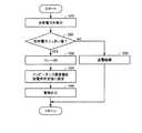
図5は、図1に示した給電設備100において、しきい値を超える反射電力が検出されるときのECU160の処理を示すフローチャートである。図5を参照して、ECU160は、電力センサ115(図1)によって検出される電源装置110への反射電力を電力センサ115から受ける(ステップS10)。そして、ECU160は、反射電力の検出値が予め定められたしきい値よりも大きいか否かを判定する(ステップS20)。なお、このしきい値は、電源装置110の仕様に基づいて適宜設定される。 FIG. 5 is a flowchart showing processing of
反射電力がしきい値よりも大きいと判定されると(ステップS20においてYES)、ECU160は、リレー190(図1)をオンにする(ステップS30)。これにより、インピーダンス整合器120と一次コイル130との間の電路にコイル180(図1)が電気的に接続され、増大した反射電力が放出用自己共振コイル185によって周囲の空間へ放出される。そして、ECU160は、警報を出力し、放出用コイルユニットから電力が放出されていることを周囲に報知する(ステップS40)。 If it is determined that the reflected power is larger than the threshold value (YES in step S20),
一方、ステップS20において反射電力がしきい値以下であると判定されると(ステップS20においてNO)、ECU160は、リレー190をオンすることなく車両200への送電を継続する(ステップS50)。 On the other hand, when it is determined in step S20 that the reflected power is equal to or less than the threshold value (NO in step S20),
以上のように、この実施の形態においては、反射電力の検出値が予め定められたしきい値を超えると、電源装置110と送電ユニットとの間に放出用コイルユニットが電気的に接続され、電源装置110から出力された電力が放出用コイルユニットにより外部へ放出される。したがって、この実施の形態によれば、反射電力の急増による電源装置110の損傷を防止することができる。 As described above, in this embodiment, when the detected value of the reflected power exceeds a predetermined threshold value, the discharge coil unit is electrically connected between the
[変形例]
電源装置110への反射電力がしきい値よりも大きいと判定されたとき、リレー190をオンするとともに、放出用自己共振コイル185と周囲の空間とのインピーダンスが整合するようにインピーダンス整合器120のインピーダンスを変更してもよい。これにより、放出用コイルユニットの設計の自由度が向上する。[Modification]
When it is determined that the reflected power to the
図6は、この変形例における給電設備100において、しきい値を超える反射電力が検出されるときのECU160の処理を示すフローチャートである。図6を参照して、このフローチャートは、図5に示したフローチャートにおいて、ステップS35をさらに含む。すなわち、ステップS30においてリレー190がオンされると、ECU160は、インピーダンス整合器120を放電用の所定値に設定する(ステップS35)。 FIG. 6 is a flowchart illustrating processing of
なお、この所定値は、放出用自己共振コイル185と周囲空間とによって形成される共鳴系の入力インピーダンスが電源装置110の出力インピーダンスと整合するように予め求められた値である。そして、インピーダンス整合器120のインピーダンスが所定値に変更されると、ECU160は、ステップS40へ処理を進め、警報が出力される。 This predetermined value is a value obtained in advance so that the input impedance of the resonance system formed by the emission self-
以上のように、この変形例によれば、反射電力の急増による電源装置110の損傷を防止できるとともに、放出用コイルユニットの設計の自由度が向上する。 As described above, according to this modification, it is possible to prevent damage to the
なお、上記の実施の形態および変形例においては、放出用コイルユニットを設けることによって過大な反射電力を外部へ放出するものとしたが、放出用コイルユニットに代えて放電抵抗を設けてもよい。 In the above-described embodiment and modification, an excessive reflected power is emitted to the outside by providing the emission coil unit. However, a discharge resistor may be provided instead of the emission coil unit.
図7は、放出用コイルユニットに代えて放電抵抗が設けられた非接触給電システムの全体構成図である。図7を参照して、この非接触給電システムは、給電設備100Aと、車両200とを備える。給電設備100Aは、図1に示した給電設備100の構成において、コイル180および放出用自己共振コイル185を含む放出用コイルユニットに代えて放電抵抗195を含む。 FIG. 7 is an overall configuration diagram of a non-contact power feeding system in which a discharge resistor is provided instead of the discharge coil unit. Referring to FIG. 7, this non-contact power feeding system includes
そして、給電設備100から車両200への給電中に反射電力の検出値が予め定められた値を超えると、リレー190がオンされる。これにより、インピーダンス整合器120と一次コイル130との間の電路に放電抵抗195が電気的に接続され、放電抵抗195において電力が消費されることによって反射電力の急増が抑制される。 When the detected value of the reflected power exceeds a predetermined value during power feeding from
なお、上記の実施の形態においては、給電設備100の一次自己共振コイル140と車両200の二次自己共振コイル210とを共鳴させて送電するものとしたが、一対の高誘電体ディスクによって送電ユニットおよび受電ユニットを構成してもよい。高誘電体ディスクは、高誘電率材から成り、たとえばTiO2やBaTi4O9、LiTaO3等が用いられる。In the above embodiment, power is transmitted by resonating the primary self-
なお、上記において、二次自己共振コイル210、コンデンサ220および二次コイル230は、この発明における「受電ユニット」の一実施例を形成し、一次コイル130、一次自己共振コイル140およびコンデンサ150は、この発明における「送電ユニット」の一実施例を形成する。また、電力センサ115は、この発明における「検出装置」の一実施例に対応し、放出用自己共振コイル185およびコイル180は、この発明における「放出用コイル」の一実施例を形成する。 In the above, secondary self-
さらに、リレー190は、この発明における「接続装置」の一実施例に対応し、シールドボックス420は、この発明における「電磁気遮蔽材」の一実施例に対応する。また、さらに、インピーダンス整合器120は、この発明における「インピーダンス可変装置」の一実施例に対応し、ECU160は、この発明における「制御装置」の一実施例に対応する。 Further,
今回開示された実施の形態は、すべての点で例示であって制限的なものではないと考えられるべきである。本発明の範囲は、上記した実施の形態の説明ではなくて請求の範囲によって示され、請求の範囲と均等の意味および範囲内でのすべての変更が含まれることが意図される。 The embodiment disclosed this time should be considered as illustrative in all points and not restrictive. The scope of the present invention is shown not by the above description of the embodiments but by the scope of claims, and is intended to include all modifications within the meaning and scope equivalent to the scope of claims.
100,100A 給電設備、110 電源装置、115 電力センサ、120 インピーダンス整合器、122,124 可変コンデンサ、126 コイル、130 一次コイル、140 一次自己共振コイル、150,220 コンデンサ、160,290 ECU、170,300 通信装置、180 コイル、185 放出用自己共振コイル、190 リレー、195 放電抵抗、200 車両、230 二次コイル、260 整流器、270 充電器、280 蓄電装置、285 動力出力装置、350 負荷、410,420,430 シールドボックス。 100, 100A power supply equipment, 110 power supply device, 115 power sensor, 120 impedance matching device, 122, 124 variable capacitor, 126 coil, 130 primary coil, 140 primary self-resonant coil, 150, 220 capacitor, 160, 290 ECU, 170, 300 communication device, 180 coil, 185 discharge self-resonant coil, 190 relay, 195 discharge resistance, 200 vehicle, 230 secondary coil, 260 rectifier, 270 charger, 280 power storage device, 285 power output device, 350 load, 410, 420,430 Shield box.
Claims (7)
Translated fromJapanese所定の周波数を有する電力を発生する電源装置と、
前記電源装置から電力を受け、前記受電ユニットと電磁場を介して共鳴することにより前記受電ユニットへ非接触で送電するための送電ユニットと、
前記電源装置への反射電力を検出するための検出装置と、
前記電源装置から出力された電力を外部へ放出するための放出用コイルまたは前記電源装置から出力された電力を消費するための抵抗によって構成される放電装置と、
前記反射電力の検出値が予め定められた値を超えたとき、前記電源装置と前記送電ユニットとの間に前記放電装置を電気的に接続する接続装置とを備える非接触給電設備。A non-contact power feeding apparatus for feeding in a non-contactto the power receivingequipment comprisinga power receivingunit,
And power supplies for generating electric power having a predetermined frequency,
A transmissionunit for transmitting in a non-contact to the power receiving unit by the receiving power from a power source device, resonates through the power receiving unit and the electromagnetic field,
And detectingequipment for detecting the reflected power to the power supply device,
Thus the constructed dischargedevice resistance for the release for carpluma other for discharging to the outside the electric power consuming power output from the power supply output from the power supply device,
When the detected value of the reflected power exceeds a predetermined value, the non-contact power feeding apparatusand a connectionequipment for electrically connecting the discharge device between the power supply device and the power transmitting unit.
前記非接触給電設備は、前記放出用コイルの周囲に配設され、かつ、前記放出用コイルから外部へ電力を放出可能なように一方向のみが開口された電磁気遮蔽材をさらに備え、
前記放出用コイルおよび前記電磁気遮蔽材は、地中に設けられ、
前記電磁気遮蔽材は、開口部が地中を向くように配設される、請求項1に記載の非接触給電設備。The discharge device is the discharge coil;
The non-contact power supply facility further includes an electromagnetic shieldingmaterial disposed around the discharge coil and opened in only one direction so that electric power can be discharged from the discharge coil to the outside.
The discharge coil and the electromagnetic shielding material are provided in the ground,
The non-contact power supply facility according toclaim 1 , wherein the electromagnetic shielding material is disposed so that an opening portion faces the ground.
前記接続装置は、前記反射電力の検出値が前記予め定められた値を超えたとき、前記インピーダンス可変装置と前記送電ユニットとの間に前記放電装置を電気的に接続する、請求項1に記載の非接触給電設備。Disposed between the power unit and the transmission unit further comprisesan impedance-friendly disguiselocation for adjusting the input impedance of the resonant system formed by the power transmission unit and the power receiving unit,
The connecting device, when the detected value of the reflected power exceeds the predetermined value, electrically connecting the discharge device between the variable impedance device and the power transmitting unit, according toclaim 1 Non-contact power supply equipment.
前記所定値は、前記放出用コイルとその周囲空間とのインピーダンスが整合するように予め設定された値である、請求項4に記載の非接触給電設備。The discharge device is the discharge coil;
The non-contact power feeding facility according toclaim 4 , wherein the predetermined value is a value set in advance so that impedances of the discharge coil and the surrounding space thereof are matched.
前記電源装置から電力を受ける一次コイルと、
前記一次コイルから電磁誘導により給電され、前記電磁場を発生する一次自己共振コイルとを含み、
前記受電ユニットは、
前記電磁場を介して前記一次自己共振コイルと共鳴することにより前記一次自己共振コイルから受電する二次自己共振コイルと、
前記二次自己共振コイルによって受電された電力を電磁誘導により取出して出力する二次コイルとを含む、請求項1から5のいずれかに記載の非接触給電設備。The power transmission unit is:
A primarycoil for receiving power from said power supply,
It said powered by electromagnetic induction from the primary coil, anda primary self-resonantcoil for generating said electromagnetic field,
The power receiving unit is:
A secondary self-resonantcoil for power reception from said primary self-resonant coil by resonating with the primary self-resonant coil via the electromagnetic field,
Anda secondarycoil for outputting a power received by said secondary self-resonant coil is taken out by electromagnetic induction, the non-contact power feeding apparatus according to any oneof claims 1 to5.
Applications Claiming Priority (1)
| Application Number | Priority Date | Filing Date | Title |
|---|---|---|---|
| PCT/JP2010/071438WO2012073348A1 (en) | 2010-12-01 | 2010-12-01 | Wireless energy-transfer equipment |
Publications (2)
| Publication Number | Publication Date |
|---|---|
| JP5152446B2true JP5152446B2 (en) | 2013-02-27 |
| JPWO2012073348A1 JPWO2012073348A1 (en) | 2014-05-19 |
Family
ID=46171333
Family Applications (1)
| Application Number | Title | Priority Date | Filing Date |
|---|---|---|---|
| JP2012542280AExpired - Fee RelatedJP5152446B2 (en) | 2010-12-01 | 2010-12-01 | Non-contact power supply equipment |
Country Status (5)
| Country | Link |
|---|---|
| US (1) | US8581445B2 (en) |
| EP (1) | EP2530811B1 (en) |
| JP (1) | JP5152446B2 (en) |
| CN (1) | CN103250325B (en) |
| WO (1) | WO2012073348A1 (en) |
Cited By (1)
| Publication number | Priority date | Publication date | Assignee | Title |
|---|---|---|---|---|
| KR20190047229A (en)* | 2017-10-27 | 2019-05-08 | 한국철도기술연구원 | Wireless Power Transmission Structure for Reefer Container |
Families Citing this family (19)
| Publication number | Priority date | Publication date | Assignee | Title |
|---|---|---|---|---|
| US8841881B2 (en) | 2010-06-02 | 2014-09-23 | Bryan Marc Failing | Energy transfer with vehicles |
| KR101222749B1 (en)* | 2010-12-14 | 2013-01-16 | 삼성전기주식회사 | Wireless power transmission apparatus and transmission method thereof |
| JP5802424B2 (en)* | 2011-04-22 | 2015-10-28 | 矢崎総業株式会社 | Resonant contactless power supply system |
| JP5732307B2 (en)* | 2011-04-22 | 2015-06-10 | 矢崎総業株式会社 | Resonant contactless power supply system |
| JP5703988B2 (en)* | 2011-06-17 | 2015-04-22 | トヨタ自動車株式会社 | Power receiving device, power transmitting device, vehicle, and non-contact power feeding system |
| US8933589B2 (en) | 2012-02-07 | 2015-01-13 | The Gillette Company | Wireless power transfer using separately tunable resonators |
| GB2501482A (en)* | 2012-04-23 | 2013-10-30 | Bombardier Transp Gmbh | Providing a land vehicle with electric energy by magnetic induction |
| JP2014017894A (en)* | 2012-07-05 | 2014-01-30 | Toyota Industries Corp | Transmitting apparatus and contactless power transmission system |
| CN102916500A (en)* | 2012-10-24 | 2013-02-06 | 天津工业大学 | Wireless electric energy transmission device for multiple sensors |
| WO2014185490A1 (en)* | 2013-05-15 | 2014-11-20 | 日本電気株式会社 | Power transfer system, power transmitting device, power receiving device, and power transfer method |
| JP6144176B2 (en)* | 2013-10-15 | 2017-06-07 | 日東電工株式会社 | Wireless power transmission device capable of forming magnetic field space and method for forming the same |
| US9672976B2 (en) | 2013-10-28 | 2017-06-06 | Nokia Corporation | Multi-mode wireless charging |
| US20150130290A1 (en)* | 2013-11-11 | 2015-05-14 | Samsung Electro-Mechanics Co., Ltd. | Wireless power transmitting apparatus and wireless power transmitting-receiving apparatus |
| KR20160101958A (en)* | 2013-12-26 | 2016-08-26 | 미쓰비시 덴끼 엔지니어링 가부시키가이샤 | Automatic matching circuit for high-frequency power supply |
| US10320230B2 (en) | 2014-03-26 | 2019-06-11 | Apple Inc. | Temperature management for inductive charging systems |
| US9780571B2 (en) | 2014-08-28 | 2017-10-03 | Motorola Solutions, Inc. | Methods and systems for providing a ballast load for a magnetic resonant power supply |
| JP2017131020A (en)* | 2016-01-19 | 2017-07-27 | 株式会社ダイヘン | Non-contact power supply system and power receiver |
| JP2018011481A (en)* | 2016-07-15 | 2018-01-18 | 日本電業工作株式会社 | Wireless charging device and wireless charging system |
| JP7043187B2 (en)* | 2017-06-14 | 2022-03-29 | 矢崎総業株式会社 | Shield member and power transmission unit |
Citations (3)
| Publication number | Priority date | Publication date | Assignee | Title |
|---|---|---|---|---|
| WO2010035321A1 (en)* | 2008-09-25 | 2010-04-01 | トヨタ自動車株式会社 | Power supply system and electric vehicle |
| JP2010141976A (en)* | 2008-12-09 | 2010-06-24 | Toyota Industries Corp | Non-contact power transmission apparatus |
| JP2010154625A (en)* | 2008-12-24 | 2010-07-08 | Toyota Industries Corp | Resonant non-contact charging device |
Family Cites Families (14)
| Publication number | Priority date | Publication date | Assignee | Title |
|---|---|---|---|---|
| GB2414120B (en)* | 2004-05-11 | 2008-04-02 | Splashpower Ltd | Controlling inductive power transfer systems |
| US7825543B2 (en) | 2005-07-12 | 2010-11-02 | Massachusetts Institute Of Technology | Wireless energy transfer |
| CN101860089B (en) | 2005-07-12 | 2013-02-06 | 麻省理工学院 | wireless non-radiative energy transfer |
| JP2007325388A (en)* | 2006-05-31 | 2007-12-13 | Hitachi Ltd | Electric motor control device and in-vehicle electric motor drive system |
| KR20110117732A (en) | 2007-03-27 | 2011-10-27 | 메사추세츠 인스티튜트 오브 테크놀로지 | Wireless energy transfer |
| JPWO2009031639A1 (en)* | 2007-09-06 | 2010-12-16 | 昭和電工株式会社 | Non-contact rechargeable power storage device |
| JP4911148B2 (en)* | 2008-09-02 | 2012-04-04 | ソニー株式会社 | Contactless power supply |
| JP2010068634A (en) | 2008-09-11 | 2010-03-25 | Yazaki Corp | Wireless charging system for vehicle |
| JP4743244B2 (en) | 2008-09-18 | 2011-08-10 | トヨタ自動車株式会社 | Non-contact power receiving device |
| US8446046B2 (en)* | 2008-10-03 | 2013-05-21 | Access Business Group International Llc | Power system |
| WO2010067763A1 (en) | 2008-12-09 | 2010-06-17 | 株式会社 豊田自動織機 | Non-contact power transmission apparatus and power transmission method using a non-contact power transmission apparatus |
| JP5238472B2 (en)* | 2008-12-16 | 2013-07-17 | 株式会社日立製作所 | Power transmission device and power reception device |
| JP2010183812A (en)* | 2009-02-09 | 2010-08-19 | Toyota Industries Corp | Resonant contactless charging system |
| CN101572444B (en)* | 2009-03-17 | 2011-06-15 | 苏州达方电子有限公司 | Wireless energy transfer system, wireless power supply module and energy supply method |
- 2010
- 2010-12-01JPJP2012542280Apatent/JP5152446B2/ennot_activeExpired - Fee Related
- 2010-12-01WOPCT/JP2010/071438patent/WO2012073348A1/ennot_activeCeased
- 2010-12-01EPEP10860256.6Apatent/EP2530811B1/ennot_activeNot-in-force
- 2010-12-01USUS13/580,518patent/US8581445B2/enactiveActive
- 2010-12-01CNCN201080067100.6Apatent/CN103250325B/ennot_activeExpired - Fee Related
Patent Citations (3)
| Publication number | Priority date | Publication date | Assignee | Title |
|---|---|---|---|---|
| WO2010035321A1 (en)* | 2008-09-25 | 2010-04-01 | トヨタ自動車株式会社 | Power supply system and electric vehicle |
| JP2010141976A (en)* | 2008-12-09 | 2010-06-24 | Toyota Industries Corp | Non-contact power transmission apparatus |
| JP2010154625A (en)* | 2008-12-24 | 2010-07-08 | Toyota Industries Corp | Resonant non-contact charging device |
Cited By (2)
| Publication number | Priority date | Publication date | Assignee | Title |
|---|---|---|---|---|
| KR20190047229A (en)* | 2017-10-27 | 2019-05-08 | 한국철도기술연구원 | Wireless Power Transmission Structure for Reefer Container |
| KR102037876B1 (en) | 2017-10-27 | 2019-10-30 | 한국철도기술연구원 | Wireless Power Transmission Structure for Reefer Container |
Also Published As
| Publication number | Publication date |
|---|---|
| US20130127242A1 (en) | 2013-05-23 |
| CN103250325A (en) | 2013-08-14 |
| US8581445B2 (en) | 2013-11-12 |
| JPWO2012073348A1 (en) | 2014-05-19 |
| CN103250325B (en) | 2015-04-08 |
| EP2530811A4 (en) | 2014-05-07 |
| EP2530811A1 (en) | 2012-12-05 |
| EP2530811B1 (en) | 2016-07-13 |
| WO2012073348A1 (en) | 2012-06-07 |
Similar Documents
| Publication | Publication Date | Title |
|---|---|---|
| JP5152446B2 (en) | Non-contact power supply equipment | |
| JP5703988B2 (en) | Power receiving device, power transmitting device, vehicle, and non-contact power feeding system | |
| JP5287863B2 (en) | Non-contact power receiving apparatus and vehicle equipped with the same | |
| JP4947241B2 (en) | Coil unit, contactless power receiving device, contactless power transmitting device, contactless power feeding system, and vehicle | |
| US9559550B2 (en) | Contactless power receiving apparatus and vehicle incorporating same, contactless power feeding facility, method of controlling contactless power receiving apparatus, and method of controlling contactless power feeding facility | |
| US9536655B2 (en) | Wireless power feeding apparatus, vehicle, and method of controlling wireless power feeding system | |
| JP5648694B2 (en) | Non-contact power supply system and power supply equipment | |
| EP2345553B1 (en) | Non-contact power transmission device and vehicle having non-contact power transmission device | |
| JP5016069B2 (en) | Power transmission system and vehicle power supply device | |
| JP5126324B2 (en) | Power supply apparatus and control method of power supply system | |
| JP5474463B2 (en) | Non-contact power receiving apparatus and electric vehicle including the same | |
| US20110148351A1 (en) | Noncontact electric power receiving device, noncontact electric power transmitting device, noncontact electric power feeding system, and electrically powered vehicle | |
| WO2011099106A1 (en) | Electric power feed device for vehicle and electric power reception device | |
| JP2010074937A (en) | Non-contact power receiving apparatus and vehicle equipped with the same | |
| JP5474470B2 (en) | Non-contact power receiving apparatus and electric vehicle including the same | |
| JP2010073885A (en) | Resonance coil and non-contact feeding system | |
| RU2461946C1 (en) | Device for non-contact power generation and transport means containing such device | |
| JP2011166931A (en) | Power receiving device and vehicle including the same | |
| CN103522902A (en) | Non-contact powered device and vehicle provided with non-contact powered device |
Legal Events
| Date | Code | Title | Description |
|---|---|---|---|
| TRDD | Decision of grant or rejection written | ||
| A01 | Written decision to grant a patent or to grant a registration (utility model) | Free format text:JAPANESE INTERMEDIATE CODE: A01 Effective date:20121106 | |
| A61 | First payment of annual fees (during grant procedure) | Free format text:JAPANESE INTERMEDIATE CODE: A61 Effective date:20121119 | |
| FPAY | Renewal fee payment (event date is renewal date of database) | Free format text:PAYMENT UNTIL: 20151214 Year of fee payment:3 | |
| R151 | Written notification of patent or utility model registration | Ref document number:5152446 Country of ref document:JP Free format text:JAPANESE INTERMEDIATE CODE: R151 | |
| FPAY | Renewal fee payment (event date is renewal date of database) | Free format text:PAYMENT UNTIL: 20151214 Year of fee payment:3 | |
| LAPS | Cancellation because of no payment of annual fees |