JP5152285B2 - Surgical holder - Google Patents
Surgical holderDownload PDFInfo
- Publication number
- JP5152285B2 JP5152285B2JP2010200482AJP2010200482AJP5152285B2JP 5152285 B2JP5152285 B2JP 5152285B2JP 2010200482 AJP2010200482 AJP 2010200482AJP 2010200482 AJP2010200482 AJP 2010200482AJP 5152285 B2JP5152285 B2JP 5152285B2
- Authority
- JP
- Japan
- Prior art keywords
- surgical
- gripping
- holding
- main body
- surgical treatment
- Prior art date
- Legal status (The legal status is an assumption and is not a legal conclusion. Google has not performed a legal analysis and makes no representation as to the accuracy of the status listed.)
- Expired - Fee Related
Links
- 238000001356surgical procedureMethods0.000claimsdescription33
- 229920005989resinPolymers0.000claimsdescription9
- 239000011347resinSubstances0.000claimsdescription9
- 239000000463materialSubstances0.000claimsdescription5
- 229930182556PolyacetalNatural products0.000claimsdescription3
- 229920000491PolyphenylsulfonePolymers0.000claimsdescription3
- 239000004743PolypropyleneSubstances0.000claimsdescription3
- 229920006311Urethane elastomerPolymers0.000claimsdescription3
- 229920005668polycarbonate resinPolymers0.000claimsdescription3
- 239000004431polycarbonate resinSubstances0.000claimsdescription3
- 229920006324polyoxymethylenePolymers0.000claimsdescription3
- -1polypropylenePolymers0.000claimsdescription3
- 229920001155polypropylenePolymers0.000claimsdescription3
- 229920002379silicone rubberPolymers0.000claimsdescription3
- 239000004945silicone rubberSubstances0.000claimsdescription3
- 229910001220stainless steelInorganic materials0.000claimsdescription3
- 239000010935stainless steelSubstances0.000claimsdescription3
- 230000003872anastomosisEffects0.000description7
- 210000004351coronary vesselAnatomy0.000description7
- 238000000034methodMethods0.000description5
- 238000007796conventional methodMethods0.000description3
- 210000004204blood vesselAnatomy0.000description2
- 210000000038chestAnatomy0.000description2
- 238000003780insertionMethods0.000description2
- 230000037431insertionEffects0.000description2
- 208000028867ischemiaDiseases0.000description2
- 238000012986modificationMethods0.000description2
- 230000004048modificationEffects0.000description2
- 238000011282treatmentMethods0.000description2
- 208000031481Pathologic ConstrictionDiseases0.000description1
- 208000007536ThrombosisDiseases0.000description1
- 206010047141VasodilatationDiseases0.000description1
- 230000002612cardiopulmonary effectEffects0.000description1
- 230000000694effectsEffects0.000description1
- 210000004300gastroepiploic arteryAnatomy0.000description1
- 238000002695general anesthesiaMethods0.000description1
- 210000001349mammary arteryAnatomy0.000description1
- 208000010125myocardial infarctionDiseases0.000description1
- 208000031225myocardial ischemiaDiseases0.000description1
- 230000002093peripheral effectEffects0.000description1
- 229920002635polyurethanePolymers0.000description1
- 239000004814polyurethaneSubstances0.000description1
- 230000010349pulsationEffects0.000description1
- 239000003381stabilizerSubstances0.000description1
- 230000036262stenosisEffects0.000description1
- 208000037804stenosisDiseases0.000description1
- 210000001562sternumAnatomy0.000description1
- 230000024883vasodilationEffects0.000description1
Images


Landscapes
- Surgical Instruments (AREA)
Description
Translated fromJapanese本発明は、手術用保持具に関する。The present invention relates to a surgical holder.
近年、心筋梗塞等の虚血性心疾患を抱えた患者に対するカテーテルインターベーションが加速度的に普及してきた。代表的なカテーテルインターベーションには、冠動脈血管拡張術や血管内ステント留置があるが、これらの治療は患者に対し低浸襲であり、入院期間が短いという利点を有する。
一方、カテーテル治療の対象とならない患者には、人工心肺を用いる冠動脈バイパス術(以下CABGと略す)の有効性が広く認知されている。この方法は、虚血の原因である狭窄の起こっている冠動脈の末梢側に剥離した内胸動脈、胃大網動脈等のバイパス用血管の一端を吻合し、虚血の解消を図る方法である。In recent years, catheter intervention for patients with ischemic heart diseases such as myocardial infarction has been rapidly spreading. Typical catheter interventions include coronary vasodilatation and endovascular stenting, but these treatments have the advantage of low invasiveness to the patient and a short hospital stay.
On the other hand, the effectiveness of coronary artery bypass surgery (hereinafter abbreviated as CABG) using cardiopulmonary bypass is widely recognized for patients who are not subject to catheter treatment. This method is intended to eliminate ischemia by anastomosing one end of bypass blood vessels such as the internal thoracic artery and gastroepiploic artery that have been exfoliated to the peripheral side of the coronary artery in which stenosis causing ischemia has occurred. .
近年、人工心肺を使用しないで、心拍動下でバイパス用グラフトを吻合する方法が試みられ、良好な成績が得られるようになった。この方法は、心拍動下冠状動脈バイパス術と呼ばれている。心拍動下冠状動脈バイパス術の問題点は、心臓が動いているために、完璧な吻合を短時間で実施するには熟練を要することである。吻合が不良であれば吻合部から冠動脈やバイパス用血管内に血の塊が発生して閉塞してしまう原因となる。この問題は、心臓の吻合部を圧迫し、心臓の拍動を緩和させて、吻合部を安定化するような手術用処置具(スタビライザー)を使用することで改善された。さらに、心臓の位置を調整するような手術用処置具(ポジショナー)を使用することにより、心臓の吻合部を正面視することが可能となり、より精度が高い吻合部を作成することが可能となったため、心拍動下冠状動脈バイパス術の成績は飛躍的に向上した。In recent years, attempts have been made to anastomote bypass grafts under heartbeat without using heart-lung machines, and good results have been obtained. This method is called coronary artery bypass surgery under heartbeat. The problem with coronary artery bypass surgery under heart beat is that the heart is moving, and skill is required to perform a perfect anastomosis in a short time. If the anastomosis is poor, a blood clot is generated in the coronary artery or bypass blood vessel from the anastomosis, causing the blockage. This problem has been improved by using a surgical treatment tool (stabilizer) that compresses the anastomosis of the heart, relaxes the pulsation of the heart, and stabilizes the anastomosis. Furthermore, by using a surgical treatment tool (positioner) that adjusts the position of the heart, the anastomosis portion of the heart can be viewed from the front, and an anastomosis portion with higher accuracy can be created. Therefore, the results of coronary artery bypass grafting under heartbeat improved dramatically.
心拍動下冠状動脈バイパス術では、患者の手術対象部位の周りをドレープで覆い、全身麻酔下にて前胸部を縦に切開した後、胸骨を切断し、開創器具を用いて開胸する。この開創器具により開胸された部分が術野となり、術野に露出した心臓に対して術者が手術を実施する。
心臓の位置を調整する手術用処置具(ポジショナー)として、心臓に吸着可能な吸盤部を有し、吸盤部に連結された吸引チューブを任意の位置に引張って、心臓の位置を調整するための棒状または紐状の保持部材を有するものが開示されている(例えば、特許文献1参照)。上記の手術用処置具は、通常、心臓の位置を任意に調整した後、その位置を保持するために、保持部材を開創器具の外周に位置するドレープに鉗子で固定される。In coronary artery bypass surgery under heart beat, a patient is covered with a drape around the surgical target site, the front chest is incised vertically under general anesthesia, the sternum is cut, and the chest is opened using a retractor. The part opened by this retracting device becomes the surgical field, and the surgeon performs an operation on the heart exposed to the surgical field.
As a surgical treatment tool (positioner) that adjusts the position of the heart, it has a suction cup that can be adsorbed to the heart, and pulls the suction tube connected to the suction cup to any position to adjust the position of the heart What has a rod-like or string-like holding member is disclosed (for example, refer to patent documents 1). In the above-described surgical treatment instrument, usually, after arbitrarily adjusting the position of the heart, in order to hold the position, the holding member is fixed to a drape positioned on the outer periphery of the retracting instrument with forceps.
上記のような従来実施されてきた手術用処置具の保持方法は、鉗子で固定するため、基本的に水平方向のみの固定となり、心臓の位置を高さ方向に調整する場合、例えば、高さ方向を有する別の補助器具に保持部材を固定するなどの工夫が必要だった。
本発明は上記事情に鑑みてなされたものであり、紐状及び/または棒状の保持部材を有する手術用処置具を従来方法に比べより簡便に、且つ、より確実に保持可能な手術用保持具を提供することにある。In the conventional method for holding a surgical instrument as described above, since it is fixed with forceps, it is basically fixed only in the horizontal direction. When adjusting the position of the heart in the height direction, for example, height A device such as fixing the holding member to another auxiliary device having a direction was required.
The present invention has been made in view of the above circumstances, and a surgical holding tool capable of holding a surgical treatment tool having a string-like and / or rod-like holding member more simply and more reliably than a conventional method. Is to provide.
このような目的は、下記(1)〜(7)に記載の本発明により達成される。
(1)紐状及び/又は棒状の保持部材を有する手術用処置具を保持する手術用保持具であって、
該手術用保持具は、本体部と、本体部の下方に位置する固定部と、本体部の上方に位置する手術用処置具把持部とから構成され、
前記固定部には、開創器具の板状部を嵌め込むことが可能な嵌め込み溝が付設されており、
前記手術用処置具把持部には、前記手術用処置具の紐状及び/又は棒状の保持部材を把持する部材把持用溝が少なくとも2つ並設され、前記部材把持用溝の高さがそれぞれ異なっていることを特徴とする手術用保持具。
(2)ステンレス鋼、ポリフェニルサルフォン樹脂、ポリアセタール樹脂、ポリプロピレン樹脂、及びポリカーボネート樹脂の中から選ばれた材料からなる(1)に記載の手術用保持具。
(3)前記固定部の嵌め込み溝に、固定部および開創器具の板状部より柔軟な緩衝部材が付設されている(1)または(2)に記載の手術用保持具。
(4)前記緩衝部材がシリコーンゴムまたはウレタンエラストマーからなる(3)に記載の手術用保持具。
(5)前記嵌め込み溝の上面には、前記開創器具の板状部を挟み込む幅を調整する摺動部材及び不動部材が付設されている(1)に記載の手術用保持具
(6)前記嵌め込み溝の上面には、前記摺動部材を摺動自在とするレールが付設されている(5)に記載の手術用保持具。
(7)前記手術用処置具把持部は、前記本体部及び/又は固定部に回動可能に取設されている(1)から(6)のいずれかに記載の手術用保持具。Such an object is achieved by the present invention described in the following (1) to (7).
(1) A surgical holding tool for holding a surgical treatment tool having a string-like and / or rod-like holding member,
The surgical holding tool is composed of a main body part, a fixing part located below the main body part, and a surgical treatment instrument gripping part located above the main body part,
The fixing portion is provided with a fitting groove capable of fitting the plate-like portion of the retracting device,
The surgical treatment instrument gripping portion is provided with at least two member gripping grooves for gripping the string-like and / or rod-shaped holding members of the surgical treatment instrument, and the heights of the member gripping grooves are respectively Surgical holder characterized by being different.
(2) The surgical holder according to (1), comprising a material selected from stainless steel, polyphenylsulfone resin, polyacetal resin, polypropylene resin, and polycarbonate resin.
(3) The surgical holder according to (1) or (2), wherein a buffer member that is more flexible than the fixing portion and the plate-like portion of the retractor is attached to the fitting groove of the fixing portion.
(4) The surgical holder according to (3), wherein the buffer member is made of silicone rubber or urethane elastomer.
(5) The surgical holder (6) according to (1), wherein a sliding member and a stationary member for adjusting a width for sandwiching the plate-like portion of the retractor are attached to an upper surface of the fitting groove (6). The surgical holder according to (5), wherein a rail that allows the sliding member to slide freely is attached to an upper surface of the groove.
(7) The surgical holding tool according to any one of (1) to (6), wherein the surgicaltreatment instrument gripping part is rotatably attached to the main body part and / or the fixing part.
本発明によれば、紐状及び/又は棒状の保持部材を有する手術用処置具を従来方法に比べより簡便に、且つ、より確実に保持可能な手術用保持具を提供することができる。 ADVANTAGE OF THE INVENTION According to this invention, the surgical treatment tool which can hold | maintain the surgical treatment tool which has a string-shaped and / or rod-shaped holding member more simply and more reliably than the conventional method can be provided.
以下、図面を参照にしつつ、本発明による手術用保持具について詳細に説明する。なお、図面の説明においては、同一要素には同一符号を付し、重複する説明を省略する。
図1は、本発明による手術用保持具の一実施形態を示す斜視図である。図2は、本発明による手術用保持具の別の実施形態を示す斜視図である。図3は、本発明による手術用保持具の使用時の一実施形態を示す斜視図である。図4は、本発明による手術用保持具の別の実施形態を示す斜視図である。Hereinafter, the surgical holder according to the present invention will be described in detail with reference to the drawings. In the description of the drawings, the same reference numerals are assigned to the same elements, and duplicate descriptions are omitted.
FIG. 1 is a perspective view showing an embodiment of a surgical holder according to the present invention. FIG. 2 is a perspective view showing another embodiment of the surgical holding tool according to the present invention. FIG. 3 is a perspective view showing an embodiment when the surgical holder according to the present invention is used. FIG. 4 is a perspective view showing another embodiment of the surgical holding tool according to the present invention.
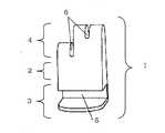
手術用保持具1は、本体部2と、本体部の下方に位置する固定部3と、本体部2の上方に位置する手術用処置具把持部4とから構成され、上記固定部3には、開創器具の板状部10を嵌め込むことが可能な嵌め込み溝5が付設される。本体部2と、固定部3とは、一体で構成されていてもいいし、別部材で構成されていても構わない。The
手術用処置具把持部4には、紐状及び/又は棒状の保持部材9を有する手術用処置具8の紐状及び/又は棒状の保持部材9を把持する部材把持用溝6が少なくとも2つ並設され、部材把持用溝6の高さはそれぞれ異なっている。
図1及び2に示す部材把持用溝6は垂直方向に併設されているが、水平方向に併設されていてもかまわない。The surgical treatment
The member gripping grooves 6 shown in FIGS. 1 and 2 are provided in the vertical direction, but may be provided in the horizontal direction.
上記部材把持用溝6の幅は、手術用処置具8の紐状及び/又は棒状の保持部材9の太さより10〜50%小さいことが好ましく、例えば、1〜5mmとすることができる。こうすることで、部材把持用溝6に手術用処置具8の保持部材9を嵌めこむだけで固定できるため、鉗子を使用して保持部材9を固定する方法より、簡便かつ確実に手術用処置具8を保持することができる。The width of the member gripping groove 6 is preferably 10 to 50% smaller than the thickness of the string-like and / or rod-
上記部材把持用溝6の高さは、特に限定されないが、例えば、手術用保持具1が固定される開創器具の板状部10の天面から、低い方の部材把持用溝6の高さを5〜50mmとし、高い方の部材把持用溝6の高さを15〜300mmとすることができる。こうすることで、心臓の位置を高さ方向に調整する場合でも、高さが高い方の部材把持用溝6に手術用処置具8の保持部材9を嵌めこむことで、高さが異なる別の補助器具を使用する必要もなく、簡便に手術用処置具8を保持することができる。また、部材把持用溝6の高さが異なるため、心臓11を任意の位置で固定することができる。これは、部材把持用溝6が水平方向に併設されていても同様であり、異なった任意の高さに形成することで上記効果を達成することができる。The height of the member gripping groove 6 is not particularly limited. For example, the height of the lower member gripping groove 6 from the top surface of the plate-like portion 10 of the retractor to which the
手術用処置具把持部4は、前記本体部2及び/または固定部3に回動可能に取設されていることが好ましい。
取設の方法は特に限定されないが、本体部2及び/または固定部3に取設用孔を設け、この孔に回動できる凸部を手術用処置具把持部4または本体部2に設けてもいいし、手術用処置具把持部4及び/または本体部2に取設用孔を設け、この孔に回動できる凸状部を本体部2または固定部3に設けても構わない。It is preferable that the surgical treatment
The mounting method is not particularly limited, but a mounting hole is provided in the
固定部3に付設された開創器具の板状部10を嵌め込むことが可能な嵌め込み溝5の幅は、特に限定されないが、例えば、5〜20mmとすることができる。こうすることで、どのような開創器具にも、本発明による手術用保持具1を固定することができる。Although the width | variety of the insertion groove |
図4に示すように、嵌め込み溝5の上面には、開創器具の板状部10を挟み込む幅を調整することが可能な摺動部材12及び不動部材13が付設されることが好ましい。更に、嵌め込み溝5の上面には、前記摺動部材12を摺動自在とするレール14が付設されていることが好ましい。このように、レール14上に摺動部材12を摺動させることにより、開創器具の板上部10の大きさに係わりなく開創器具の板上部10に本発明による手術用具1を固定することができる。As shown in FIG. 4, it is preferable that a sliding member 12 and a stationary member 13 that can adjust the width for sandwiching the plate-like portion 10 of the retracting device are attached to the upper surface of the
開創器具の板状部10を挟み込む幅を調整する方法は特に限定されないが、図4に示すように嵌め込み溝5の一方の不動部13からネジで調整する方法や、不動部13と摺動部材12との間にバネ材を付設する方法を用いることができる。Although the method of adjusting the width | variety which pinches | interposes the plate-shaped part 10 of a retractor is not specifically limited, as shown in FIG. 12 can be used.
不動部13は、嵌め込み溝5の上面に本体部2と別部材によって付設してもいいし、本体部2と一体的に形成されていても構わない。The immovable portion 13 may be attached to the upper surface of the
さらに、固定部3の嵌め込み溝5に、固定部3および開創器具の板状部10より柔軟な緩衝部材7を付設することが好ましい。こうすることで、より確実に手術用保持具1を開創器具に固定することができる。この緩衝部材7は、固定部3の嵌め込み溝5に開創器具の板状部10を嵌め込む時の操作性の観点から、図2に示すように、固定部3の内側の本体部2側に付設されることが好ましい。Furthermore, it is preferable that a
さらに、摺動部材12と及び不動部材13の開創器具の板状部10に当接する面には、上記と同様な緩衝部材7を付設することが好ましい。更に、上記緩衝部材7の硬度は、固定部3及び開創器具の板状部10の硬度よりも小さいことが好ましい。Furthermore, it is preferable to attach the
手術用保持具1の材料は、特に限定されないが、例えば、ステンレス鋼、ポリフェニルサルフォン樹脂、ポリアセタール樹脂、ポリプロピレン樹脂、及びポリカーボネート樹脂の中から選択することができる。また、固定部3のはめ込み溝5に付設することが好ましい緩衝部材7の材料は、特に限定されないが、例えば、シリコーンゴムまたはウレタンエラストマーとすることができる。また、緩衝部材7の材料は、例えば、スポンジ状の発泡ポリウレタンとすることもできる。The material of the
手術用保持具1の大きさは、特に限定されないが、例えば、幅を10〜100mmとし、長さを5〜50mm、高さを20〜400mmとすることができる。こうすることで、十分な手術作業スペースを確保できるため、安全に手術を実施することができる。Although the magnitude | size of the
以上、本発明を実施形態に基づいて説明した。これらの実施形態はあくまで例示であり、種々の変形例が可能なこと、またそうした変形例も本発明の範囲にあることは当業者に理解されるところである。The present invention has been described based on the embodiments. It is to be understood by those skilled in the art that these embodiments are merely examples, and that various modifications are possible and that such modifications are within the scope of the present invention.
1 手術用保持具
2 本体部
3 固定部
4 手術用処置具把持部
5 嵌め込み溝
6 部材把持用溝
7 緩衝部材
8 手術用処置具
9 保持部材
10 開創器具の板状部
11 心臓
12 摺動部材
13 不動部
・ 14 レールDESCRIPTION OF
Claims (7)
Translated fromJapanese該手術用保持具は、本体部と、本体部の下方に位置する固定部と、本体部の上方に位置する手術用処置具把持部とから構成され、
前記固定部には、開創器具の板状部を嵌め込むことが可能な嵌め込み溝が付設されており、
前記手術用処置具把持部には、前記手術用処置具の紐状及び/又は棒状の保持部材を把持する部材把持用溝が少なくとも2つ並設され、前記部材把持用溝の高さがそれぞれ異なっていることを特徴とする手術用保持具。A surgical holding tool for holding a surgical treatment tool having a string-like and / or rod-like holding member,
The surgical holding tool is composed of a main body part, a fixing part located below the main body part, and a surgical treatment instrument gripping part located above the main body part,
The fixing portion is provided with a fitting groove capable of fitting the plate-like portion of the retracting device,
The surgical treatment instrument gripping portion is provided with at least two member gripping grooves for gripping the string-like and / or rod-shaped holding members of the surgical treatment instrument, and the heights of the member gripping grooves are respectively Surgical holder characterized by being different.
The surgical holding tool according to any one of claims 1 to 6, wherein the surgicaltreatment tool gripping part is rotatably attached to the main body part and / or the fixing part.
Priority Applications (1)
| Application Number | Priority Date | Filing Date | Title |
|---|---|---|---|
| JP2010200482AJP5152285B2 (en) | 2009-12-08 | 2010-09-08 | Surgical holder |
Applications Claiming Priority (3)
| Application Number | Priority Date | Filing Date | Title |
|---|---|---|---|
| JP2009278444 | 2009-12-08 | ||
| JP2009278444 | 2009-12-08 | ||
| JP2010200482AJP5152285B2 (en) | 2009-12-08 | 2010-09-08 | Surgical holder |
Publications (2)
| Publication Number | Publication Date |
|---|---|
| JP2011139887A JP2011139887A (en) | 2011-07-21 |
| JP5152285B2true JP5152285B2 (en) | 2013-02-27 |
Family
ID=44456165
Family Applications (1)
| Application Number | Title | Priority Date | Filing Date |
|---|---|---|---|
| JP2010200482AExpired - Fee RelatedJP5152285B2 (en) | 2009-12-08 | 2010-09-08 | Surgical holder |
Country Status (1)
| Country | Link |
|---|---|
| JP (1) | JP5152285B2 (en) |
Families Citing this family (1)
| Publication number | Priority date | Publication date | Assignee | Title |
|---|---|---|---|---|
| CN103845089B (en)* | 2012-06-26 | 2016-03-30 | 刘希斌 | The tractive localizer of thoracoscopic operation in lobe of the lung tractive combined apparatus |
Family Cites Families (3)
| Publication number | Priority date | Publication date | Assignee | Title |
|---|---|---|---|---|
| US5967973A (en)* | 1996-04-26 | 1999-10-19 | United States Surgical | Surgical retractor and method of surgery |
| US6193652B1 (en)* | 1997-10-07 | 2001-02-27 | Ethicon Endo-Surgery, Inc. | Tissue stabilization device for use during surgery having spherical curved feet |
| ES2547723T3 (en)* | 2004-10-14 | 2015-10-08 | Sumitomo Bakelite Company, Limited | Treatment instrument for aortocoronary bypass surgery |
- 2010
- 2010-09-08JPJP2010200482Apatent/JP5152285B2/ennot_activeExpired - Fee Related
Also Published As
| Publication number | Publication date |
|---|---|
| JP2011139887A (en) | 2011-07-21 |
Similar Documents
| Publication | Publication Date | Title |
|---|---|---|
| EP1009289B1 (en) | Stabilizing the beating heart during coronary artery bypass graft surgery | |
| US20060100487A1 (en) | Surgical retractor with mounting rail | |
| ES2538992T3 (en) | Devices to close the left atrial appendage | |
| JP2005511121A (en) | Vascular collection retractor with separating member | |
| US20060178674A1 (en) | Surgical apparatus having configurable portions | |
| US20110105848A1 (en) | Laparoscopic tissue retractor | |
| WO2005011476A3 (en) | Tissue positioner | |
| ATE495703T1 (en) | ENDOSCOPIC STABILIZER FOR THE BEATING HEART AND VESSEL OCCLUSION OCCLUSION | |
| US10149672B2 (en) | Devices and methods for stabilizing tissue | |
| JP5933865B1 (en) | Medical dilator | |
| JP2000060861A (en) | Wound retraction device for surgery | |
| US7022126B2 (en) | Clamping device for anatomical structure | |
| JP2008284108A (en) | Stabilizer | |
| Troisi et al. | Modified hanging maneuver using the goldfinger dissector in laparoscopic right and left hepatectomy | |
| EP1800606A1 (en) | Treatment instrument for coronary artery bypass operation | |
| JP5152285B2 (en) | Surgical holder | |
| KR200481188Y1 (en) | Endo-retractor for breast surgery | |
| EP2534999B1 (en) | Endoscope-holding device and endoscopic system | |
| JP2005237945A (en) | Coronary artery bypass surgery instrument | |
| RU2337636C2 (en) | Method of laparolifting and retractor for its realisation | |
| US11019985B2 (en) | Medical tools and related methods of use | |
| JP2010200913A (en) | Guide device | |
| JP2019170862A (en) | Medical equipment | |
| WO2019225706A1 (en) | Surgical treatment device | |
| TWI663952B (en) | Built-in device for forming pneumoperitoneum-free operation area |
Legal Events
| Date | Code | Title | Description |
|---|---|---|---|
| A977 | Report on retrieval | Free format text:JAPANESE INTERMEDIATE CODE: A971007 Effective date:20120614 | |
| A131 | Notification of reasons for refusal | Free format text:JAPANESE INTERMEDIATE CODE: A131 Effective date:20120619 | |
| A521 | Written amendment | Free format text:JAPANESE INTERMEDIATE CODE: A523 Effective date:20120626 | |
| TRDD | Decision of grant or rejection written | ||
| A01 | Written decision to grant a patent or to grant a registration (utility model) | Free format text:JAPANESE INTERMEDIATE CODE: A01 Effective date:20121106 | |
| A61 | First payment of annual fees (during grant procedure) | Free format text:JAPANESE INTERMEDIATE CODE: A61 Effective date:20121119 | |
| FPAY | Renewal fee payment (event date is renewal date of database) | Free format text:PAYMENT UNTIL: 20151214 Year of fee payment:3 | |
| R150 | Certificate of patent or registration of utility model | Ref document number:5152285 Country of ref document:JP Free format text:JAPANESE INTERMEDIATE CODE: R150 Free format text:JAPANESE INTERMEDIATE CODE: R150 | |
| LAPS | Cancellation because of no payment of annual fees |