JP5152059B2 - Power amplification device and power amplification method - Google Patents
Power amplification device and power amplification methodDownload PDFInfo
- Publication number
- JP5152059B2 JP5152059B2JP2009068422AJP2009068422AJP5152059B2JP 5152059 B2JP5152059 B2JP 5152059B2JP 2009068422 AJP2009068422 AJP 2009068422AJP 2009068422 AJP2009068422 AJP 2009068422AJP 5152059 B2JP5152059 B2JP 5152059B2
- Authority
- JP
- Japan
- Prior art keywords
- signal
- distortion compensation
- amplitude
- unit
- transmission signal
- Prior art date
- Legal status (The legal status is an assumption and is not a legal conclusion. Google has not performed a legal analysis and makes no representation as to the accuracy of the status listed.)
- Expired - Fee Related
Links
Images


Classifications
- H—ELECTRICITY
- H03—ELECTRONIC CIRCUITRY
- H03F—AMPLIFIERS
- H03F1/00—Details of amplifiers with only discharge tubes, only semiconductor devices or only unspecified devices as amplifying elements
- H03F1/02—Modifications of amplifiers to raise the efficiency, e.g. gliding Class A stages, use of an auxiliary oscillation
- H03F1/0205—Modifications of amplifiers to raise the efficiency, e.g. gliding Class A stages, use of an auxiliary oscillation in transistor amplifiers
- H03F1/0211—Modifications of amplifiers to raise the efficiency, e.g. gliding Class A stages, use of an auxiliary oscillation in transistor amplifiers with control of the supply voltage or current
- H03F1/0216—Continuous control
- H03F1/0222—Continuous control by using a signal derived from the input signal
- H—ELECTRICITY
- H03—ELECTRONIC CIRCUITRY
- H03F—AMPLIFIERS
- H03F1/00—Details of amplifiers with only discharge tubes, only semiconductor devices or only unspecified devices as amplifying elements
- H03F1/32—Modifications of amplifiers to reduce non-linear distortion
- H03F1/3241—Modifications of amplifiers to reduce non-linear distortion using predistortion circuits
- H03F1/3247—Modifications of amplifiers to reduce non-linear distortion using predistortion circuits using feedback acting on predistortion circuits
Landscapes
- Engineering & Computer Science (AREA)
- Power Engineering (AREA)
- Physics & Mathematics (AREA)
- Nonlinear Science (AREA)
- Amplifiers (AREA)
- Transmitters (AREA)
Description
Translated fromJapanese本発明は、増幅器の電圧制御と歪補償を行う電力増幅装置及び電力増幅方法に関する。 The present invention relates to a power amplifying apparatus and a power amplifying method for performing voltage control and distortion compensation of an amplifier.
無線通信に利用される電力増幅装置では高い電力効率が求められる。しかし、電力増幅器の線形性と効率は一般に相反する特性であり、これを両立させるためにこれまで様々な歪補償方法が提案されている。 High power efficiency is required in a power amplifying apparatus used for wireless communication. However, the linearity and efficiency of a power amplifier are generally contradictory characteristics, and various distortion compensation methods have been proposed so far to achieve both.
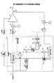
図1は、従来の電力増幅装置の一例の構成図を示す。図1において、端子1には送信信号(I,Q)が供給される。この送信信号は電圧制御部2と歪補償部3に供給される。電圧制御部2は送信信号(I,Q)の振幅を求め、この振幅に基づいた電圧信号を生成する。この電圧信号は遅延部4を経て電圧制御増幅器5の電源端子に供給される。 FIG. 1 shows a configuration diagram of an example of a conventional power amplifying apparatus. In FIG. 1, a transmission signal (I, Q) is supplied to a
歪補償部3はプリディストーション信号生成部6と係数更新部7を有している。プリディストーション信号生成部6は、例えば級数型歪補償方式でプリディストーション信号を生成する。このプリディストーション信号は遅延部8を経て直交変調器9に供給され直交変調される。直交変調器9の出力する無線周波数の直交変調信号は電圧制御増幅器5の入力端子に供給される。 The
電圧制御増幅器5は電源端子に供給される電圧信号に応じて増幅特性を変化させて直交変調信号の電力増幅を行う。電圧制御増幅器5の出力信号は方向性結合器10を経て端子11より出力される。直交変調信号の一部は方向性結合器10から取り出され直交復調器12にて直交復調される。得られた復調信号(I,Q)はフィルタ13を経て係数更新部7に供給される。 The
係数更新部7は、プリディストーション信号生成部6と同一構成のプリディストーション信号生成部14と減算器15と係数更新部16を有している。 The coefficient update unit 7 includes a predistortion
プリディストーション信号生成部14は復調信号からプリディストーション信号を生成して減算器15に供給し、また、復調信号を係数更新部16に供給する。減算器15はプリディストーション信号生成部6の出力する送信信号のプリディストーション信号からプリディストーション信号生成部14の出力する復調信号のプリディストーション信号を減算して差分を求め、係数更新部16に供給する。係数更新部16は歪補償係数を算出し、この歪補償係数を新たな歪補償係数としてプリディストーション信号生成部6,14それぞれに供給する。 The predistortion
ところで、極座標変調方式で、振幅信号の振幅値,送信レベル情報に対する遅延量情報をテーブルデータとして格納しておき、振幅信号,送信レベル情報を参照信号として遅延調整を行うことが提案されている(例えば特許文献1参照)。 By the way, it has been proposed to store the amplitude value of the amplitude signal and delay amount information with respect to transmission level information as table data in the polar modulation method, and perform delay adjustment using the amplitude signal and transmission level information as a reference signal ( For example, see Patent Document 1).
また、極座標変調方式で、定常状態での振幅補正を行った振幅情報に対して振幅調整を実施することで制御電圧の変化に対する増幅器の出力信号振幅の応答性を向上させることが提案されている(例えば特許文献2参照)。 It has also been proposed to improve the responsiveness of the output signal amplitude of the amplifier to changes in control voltage by performing amplitude adjustment on amplitude information that has been subjected to amplitude correction in a steady state by a polar modulation method. (For example, refer to Patent Document 2).
電源端子に供給する電圧信号を送信信号に応じて変化させる電圧制御増幅器5では、電圧制御増幅器5に供給する電圧信号と送信信号のタイミングを遅延部8にて調整する必要がある。通常、このタイミング調整は工場調整時に行われ、その後の遅延部8の遅延量は固定され、運用中は可変制御されていない。 In the
このため、電圧制御部2,遅延部4,歪補償部3,遅延部8,直交変調器9等の各電子部品の温度変化や経年変化によって、電圧制御部2,遅延部4の経路と、歪補償部3,遅延部8,直交変調器9の経路との間で、経路長特性に変化が生じた場合に、電圧信号と送信信号のタイミングがずれて送信特性が劣化するという問題があった。 For this reason, the path of the
開示の電力増幅装置は、電圧制御増幅器に供給する電圧信号と送信信号のタイミングのずれを低減できることを目的とする。 It is an object of the disclosed power amplifying apparatus to reduce a difference in timing between a voltage signal supplied to a voltage control amplifier and a transmission signal.
開示の一実施形態による電力増幅装置は、増幅器と、前記増幅器に供給する電圧信号を送信信号に応じて制御する電圧制御部と、前記送信信号に前記増幅器の入力対出力特性の逆特性を予め与えて歪補償処理を行う歪補償部とを備え、前記歪補償部の出力信号を前記増幅器に入力して増幅する電力増幅装置であって、前記送信信号の振幅を検出する振幅検出部と、前記送信信号の振幅の検出値が前記送信信号の最大振幅より十分に小さい値の所定値未満のときの、前記送信信号に対する前記歪補償部の出力信号の振幅を低減するように、前記歪補償部の出力信号と前記電圧信号のタイミングを調整するタイミング調整部と、を備える。A power amplification device according to an embodiment of the disclosure includes an amplifier, a voltage control unit that controls a voltage signal supplied to the amplifier according to a transmission signal, and an inverse characteristic of an input-to-output characteristic of the amplifier in the transmission signal in advance. A distortion compensation unit that performs distortion compensation processing, and is an electric power amplifying device that inputs and amplifies the output signal of the distortion compensation unit to the amplifier, and an amplitude detection unit that detects the amplitude of the transmission signal; When the detected value of the amplitude of thetransmission signal is less than a predetermined valuethat is sufficiently smaller than the maximum amplitude of the transmission signal, the distortion compensation is performed so as to reduce the amplitude of the output signal of the distortion compensation unit with respect to the transmission signal. And a timing adjustment unit that adjusts the timing of the voltage signal.
本実施形態によれば、電圧制御増幅器に供給する電圧信号と送信信号のタイミングのずれを低減できる。 According to the present embodiment, it is possible to reduce the timing difference between the voltage signal supplied to the voltage control amplifier and the transmission signal.
以下、図面に基づいて実施形態を説明する。 Embodiments will be described below with reference to the drawings.
<第1実施形態>
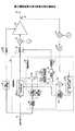
図2は、電力増幅装置の第1実施形態の構成図を示す。図2において、端子21には送信信号(I,Q)が供給される。この送信信号は電圧制御部22と歪補償部23に供給される。電圧制御部22は送信信号(I,Q)の振幅[(I2+Q2)1/2]を求め、この振幅を関数Fに代入し、振幅に基づいた電圧信号を生成する。ここで、関数Fは、例えば振幅値が所定値α未満では一定値の電圧信号とし、振幅値が所定値α(αは例えば送信信号の最大振幅の数分の1程度)を超えると振幅値に比例した値の電圧信号とするような関数である。この電圧信号は遅延部24を経て電圧制御増幅器25の電源端子に供給される。<First Embodiment>
FIG. 2 is a configuration diagram of the first embodiment of the power amplifying device. In FIG. 2, a transmission signal (I, Q) is supplied to the terminal 21. This transmission signal is supplied to the
歪補償部23はプリディストーション信号生成部26と遅延制御部27とプリディストーション信号生成部28aと減算器28bと係数更新部28cを有している。プリディストーション信号生成部26は、例えば級数型歪補償方式でプリディストーション信号を生成する。なお、プリディストーション信号生成部26としては、ルックアップテーブル方式を用いても良い。 The
級数型歪補償方式のプリディストーション信号生成部は、図3に示すように、送信信号x(t)の累乗を行う累乗部801〜80nと、累乗部801〜80nの出力に係数を乗算する乗算部811〜81nと、乗算部811〜81n出力の総和をとる加算部82とを有している。この構成により、図3の下部に示すプリディストーション信号y(n)を生成して加算部82から出力する。Pre-distortion signal generating section of a series type distortion compensation system, as shown in FIG. 3, a
なお、プリディストーション信号生成部26としては、例えば送信信号の振幅及び振幅の増分からアドレスを生成して歪補償係数テーブルをアクセスし、歪補償係数テーブルから歪補償係数を読み出す。そして、送信信号に歪補償係数を複素乗算することで、電圧制御増幅器25の歪み特性と逆の特性を与えたプリディストーション信号を生成するルックアップテーブル方式を用いても良い。 For example, the predistortion
このプリディストーション信号は遅延部31を経て直交変調器32に供給され直交変調される。直交変調器32の出力する無線周波数の直交変調信号は電圧制御増幅器25の入力端子に供給される。 This predistortion signal is supplied to the
電圧制御増幅器25は電源端子に供給される電圧信号に応じて増幅特性を変化させて直交変調信号の電力増幅を行う。電圧制御増幅器25の出力信号は方向性結合器33を経て端子34より出力される。直交変調信号の一部は方向性結合器33から取り出され直交復調器35にて直交復調される。得られた復調信号(I,Q)はフィルタ36を経てプリディストーション信号生成部28aに供給される。 The
プリディストーション信号生成部28aはプリディストーション信号生成部26と同一構成であり、復調信号からプリディストーション信号を生成して減算器28bに供給し、また、復調信号を係数更新部28cに供給する。減算器28bはプリディストーション信号生成部26の出力する送信信号のプリディストーション信号からプリディストーション信号生成部28aの出力する復調信号のプリディストーション信号を減算して差分を求め、係数更新部28cに供給する。係数更新部28cは(1)式を用いて歪補償係数h1〜hnを算出し、この歪補償係数h1〜hnを新たな歪補償係数としてプリディストーション信号生成部26,28aそれぞれに供給する。The predistortion
以下に、歪補償係数h1〜hnの生成式を示す。ここで、x(t)は送信信号、r(t)は復調信号、e(t)は差分、μ1〜μnは係数、nは次数である。
h1(t)=h1(t−1)+μ1e(t)r(t)
h2(t)=h2(t−1)+μ2e(t)|r(t)|r(t)
………
hn(t)=hn(t−1)+μne(t)|r(t)|(n−1)r(t)
…(1)Hereinafter, a production equation of the
h1 (t) = h1 (t−1) + μ1 e (t) r (t)
h2 (t) = h2 (t−1) + μ2 e (t) | r (t) | r (t)
………
hn (t) = hn (t−1) + μn e (t) | r (t) |(n−1) r (t)
... (1)
次に、遅延制御部27について説明する。遅延制御部27内の振幅変換部40は端子21から供給される送信信号の振幅[(I2+Q2)1/2]を求め、振幅判定部41に供給する。振幅判定部41は振幅値が所定値β未満で、かつ、所定値α(<β)以上の値であるか否かを判定する。ここで、所定値βは例えば送信信号の最大振幅より十分に小さい値であり、例えば送信信号の最大振幅の4/5程度の値である。振幅判定部41は振幅値が所定値β未満かつ所定値α以上であるときスイッチオン信号を生成してスイッチ42に供給する。このように、振幅値が所定値β未満の部分でスイッチオンとしているのは、電圧制御増幅器25における送信信号とプリディストーション信号とのタイミングのずれに対して、送信信号が所定値β未満の部分でプリディストーション信号の振幅が大きく変化するからである。Next, the
スイッチ42はプリディストーション信号生成部26からプリディストーション信号を供給されており、振幅判定部41からスイッチオン信号を供給されているときにオンする。スイッチ42はオン時に上記プリディストーション信号を平均振幅部43に供給する。平均振幅部43はスイッチ42のオン時におけるプリディストーション信号の振幅を求め、更に平均振幅を求める。 The switch 42 is supplied with a predistortion signal from the predistortion
平均振幅部43で得たプリディストーション信号の平均振幅値は比較部44に供給されると共に、遅延部45においてフィードバック制御で歪補償係数が更新されるのに要する時間である所定時間Dだけ遅延されて比較部44に供給される。比較部44は遅延されていない平均振幅値と遅延された平均振幅値とを比較して比較結果を制御部46に供給する。制御部46は比較結果に応じて遅延部31の遅延時間を可変調整する。なお、制御部46は遅延部31の代りに遅延部24の遅延時間を可変調整する構成としても良い。 The average amplitude value of the predistortion signal obtained by the
この実施形態では、振幅検出部の一例として振幅変換部40を用い、タイミング調整部の一例として遅延制御部27,遅延部31を用いている。 In this embodiment, the
<プリディストーション信号波形>
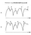
電圧制御増幅器25に入力される送信信号と電圧制御増幅器25に入力される電圧信号との間でタイミングの差がある場合について考える。この場合には、電圧信号の電圧が不充分である期間が発生するため、図4(A)に示す振幅波形の送信信号(プリディストーションを行っていない信号)に対し、電圧制御増幅器25の出力信号は所望の振幅より小さくなり、図4(B)に示すような欠損部a1〜a5を生じ、又は図4(C)に示すような欠損部b1〜b5を生じる。<Predistortion signal waveform>
Consider a case where there is a timing difference between a transmission signal input to the
このような所望の振幅より小さい電圧制御増幅器25の出力信号がフィードバックされた状態で係数更新部28によりプリディストーション信号生成部26の歪補償係数を更新すると、振幅の小さい欠損部を補うように欠損部に対応する歪補償係数が大きくなる。これにより、歪補償係数の分散値も大きくなる。すなわち、図4(B)に示す出力信号の欠損部a1〜a5に対して、プリディストーション信号は図5(A)に示す突出部c1〜c5が発生し、最大振幅より小さい部分のプリディストーション信号の平均値は大きくなる。 When the distortion compensation coefficient of the predistortion
また、図4(C)に示す出力信号の欠損部b1〜b5に対して、プリディストーション信号は図5(B)に示すように突出部d1〜d5が発生し、最大振幅より小さい部分のプリディストーション信号の平均値は大きくなる。 Further, as shown in FIG. 5 (B), the predistortion portions b1 to d5 are generated as shown in FIG. 5 (B), and the predistortion portions smaller than the maximum amplitude are generated. The average value of the distortion signal increases.
したがって、歪補償係数が更新された後に、最大振幅より小さい部分のプリディストーション信号の平均振幅値が小さくなるように遅延部31の遅延時間を可変調整することで、電圧制御増幅器25に入力される送信信号と電圧制御増幅器25に入力される電圧信号とのタイミングを一致する方向に近づけることができる。 Therefore, after the distortion compensation coefficient is updated, the delay time of the
<遅延調整処理のフローチャート>
図6は電力増幅装置が実行する遅延調整処理の一実施形態のフローチャートを示す。図6において、ステップS1で初期設定を行う。次に、ステップS2で制御部46は遅延部31の遅延時間(タイミング)をデフォルト値であるT0に設定する(状態A)。この状態AにおいてステップS2で係数更新部28cは歪補償係数を生成して、プリディストーション信号生成部26,28aそれぞれの歪補償係数を更新する。そして、ステップS3で平均振幅部43は平均振幅値Aを求める。<Flowchart of delay adjustment processing>
FIG. 6 shows a flowchart of an embodiment of a delay adjustment process executed by the power amplification device. In FIG. 6, initial setting is performed in step S1. Next, in step S2, the control unit 46 sets the delay time (timing) of the
次に、ステップS4で制御部46は遅延部31の遅延時間(タイミング)をT0から微少時間Δtだけ延長した値であるT1に設定する(状態B)。この状態BにおいてステップS5で係数更新部28は歪補償係数を生成して、プリディストーション信号生成部26,28aそれぞれの歪補償係数を更新する。そして、ステップS6で平均振幅部43は平均振幅値Bを求める。 Next, in step S4, the control unit 46 sets the delay time (timing) of the
この後、ステップS7で比較部44は平均振幅値Aと平均振幅値Bを比較する。A>Bであれば、平均振幅値が小さくなり送信信号と電圧信号とのタイミングを一致する方向に近づいているため、ステップS8で制御部46は平均振幅値Aを平均振幅値Bで置き換え、T0をT1で置き換えてステップS4に進み、ステップS4〜S7を繰り返す。 Thereafter, in step S7, the
一方、ステップS7でA≦Bであれば、ステップS9において自ステップS9の実行が1回目であるかを判別する。1回目であればステップS10で微少時間Δtの符号を負に変更してステップS4に進み、ステップS4〜S7を繰り返す。つまり、当初、遅延時間(タイミング)をT0から微少時間Δtずつ延長していれば、ステップS10を実行することにより、以降は遅延時間(タイミング)を微少時間Δtずつ短縮することになる。ステップS9で2回目以降であれば、この処理を終了する。 On the other hand, if A ≦ B in step S7, it is determined in step S9 whether or not the execution of step S9 is the first time. If it is the first time, the sign of the minute time Δt is changed to negative in step S10, the process proceeds to step S4, and steps S4 to S7 are repeated. That is, if the delay time (timing) is initially extended from T0 by the minute time Δt, the delay time (timing) is reduced by the minute time Δt thereafter by executing step S10. If it is the second time or later in step S9, this process ends.
この処理を実行することにより、平均振幅値が最小となる歪補償係数を生成できる。したがって、温度変化や経年変化の影響によらず、電圧制御増幅器における電圧信号と送信信号のタイミングのずれを低減することができる。 By executing this processing, a distortion compensation coefficient that minimizes the average amplitude value can be generated. Therefore, it is possible to reduce the timing difference between the voltage signal and the transmission signal in the voltage control amplifier regardless of the influence of temperature change or aging change.
<第2実施形態>
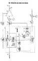
図7は、電力増幅装置の第2実施形態の構成図を示す。図7において図2と同一部分には同一符号を付す。Second Embodiment
FIG. 7 shows a configuration diagram of a second embodiment of the power amplifying device. In FIG. 7, the same parts as those in FIG.
図7において、端子21には送信信号(I,Q)が供給される。この送信信号は電圧制御部22と歪補償部23に供給される。電圧制御部22は送信信号(I,Q)の振幅[(I2+Q2)1/2]を求め、この振幅を関数Fに代入し、振幅に基づいた電圧信号を生成する。ここで、関数Fは、例えば振幅値が所定値α未満では一定値の電圧信号とし、振幅値が所定値α(αは例えば送信信号の最大振幅の数分の1程度)を超えると振幅値に比例した値の電圧信号とするような関数である。この電圧信号は遅延部24を経て電圧制御増幅器25の電源端子に供給される。In FIG. 7, a transmission signal (I, Q) is supplied to the terminal 21. This transmission signal is supplied to the
歪補償部23はプリディストーション信号生成部26と遅延制御部50とプリディストーション信号生成部28aと減算器28bと係数更新部28cを有している。プリディストーション信号生成部26は、例えば級数型歪補償方式でプリディストーション信号を生成する。なお、プリディストーション信号生成部26としては、ルックアップテーブル方式を用いても良い。 The
このプリディストーション信号は遅延部31を経て直交変調器32に供給され直交変調される。直交変調器32の出力する無線周波数の直交変調信号は電圧制御増幅器25の入力端子に供給される。 This predistortion signal is supplied to the
電圧制御増幅器25は電源端子に供給される電圧信号に応じて増幅特性を変化させて直交変調信号の電力増幅を行う。電圧制御増幅器25の出力信号は方向性結合器33を経て端子34より出力される。直交変調信号の一部は方向性結合器33から取り出され直交復調器35にて直交復調される。得られた復調信号(I,Q)はフィルタ36を経てプリディストーション信号生成部28aに供給される。 The
プリディストーション信号生成部28aはプリディストーション信号生成部26と同一構成であり、復調信号からプリディストーション信号を生成して減算器28bに供給し、また、復調信号を係数更新部28cに供給する。減算器28bはプリディストーション信号生成部26の出力する送信信号のプリディストーション信号からプリディストーション信号生成部28aの出力する復調信号のプリディストーション信号を減算して差分を求め、係数更新部28cに供給する。係数更新部28cは(1)式を用いて歪補償係数h1〜hnを算出し、この歪補償係数h1〜hnを新たな歪補償係数としてプリディストーション信号生成部26,28aそれぞれに供給する。The predistortion
以下に、歪補償係数h1〜hnの生成式を示す。ここで、x(t)は送信信号、r(t)は復調信号、e(t)は差分、μ1〜μnは係数、nは次数である。
h1(t)=h1(t−1)+μ1e(t)r(t)
h2(t)=h2(t−1)+μ2e(t)|r(t)|r(t)
………
hn(t)=hn(t−1)+μne(t)|r(t)|(n−1)r(t)
…(1)Hereinafter, a production equation of the
h1 (t) = h1 (t−1) + μ1 e (t) r (t)
h2 (t) = h2 (t−1) + μ2 e (t) | r (t) | r (t)
………
hn (t) = hn (t−1) + μn e (t) | r (t) |(n−1) r (t)
... (1)
次に、遅延制御部50について説明する。遅延制御部50内の振幅変換部40は端子21から供給される送信信号の振幅[(I2+Q2)1/2]を求め、振幅判定部41及び傾き算出部51に供給する。振幅判定部41は振幅値が所定値β未満で、かつ、所定値α(<β)以上の値であるか否かを判定する。ここで、所定値βは例えば送信信号の最大振幅より十分に小さい値であり、例えば送信信号の最大振幅の4/5程度の値である。振幅判定部41は振幅値が所定値β未満かつ所定値α以上であるときスイッチオン信号を生成してスイッチ42に供給する。このように、振幅値が所定値β未満の部分でスイッチオンとしているのは、電圧制御増幅器25における送信信号とプリディストーション信号とのタイミングのずれに対して、送信信号が所定値β未満の部分でプリディストーション信号の振幅が大きく変化するからである。Next, the
傾き算出部51は、送信信号の振幅が増大する傾きが正(+)の状態か、又は、送信信号の振幅が減少する傾きが負(−)の状態かを判別し、判別結果を平均振幅部52,53に供給する。 The
スイッチ42はプリディストーション信号生成部26からプリディストーション信号を供給されており、振幅判定部41からスイッチオン信号を供給されているときにオンする。スイッチ42はオン時に上記プリディストーション信号を平均振幅部52,53に供給する。 The switch 42 is supplied with a predistortion signal from the predistortion
平均振幅部52は、傾きが正の場合にのみ、スイッチ42のオン時におけるプリディストーション信号の振幅を求め、更に平均振幅を求める。平均振幅部53は、傾きが負の場合にのみ、スイッチ42のオン時におけるプリディストーション信号の振幅を求め、更に平均振幅を求める。平均振幅部52,53それぞれで得たプリディストーション信号の平均振幅値は比較部54に供給される。 The
ところで、図4(B)に示す出力信号の振幅の傾きが正の部分においてプリディストーション信号に図5(A)に示す突出部c1〜c5が発生して、傾きが正の部分においてプリディストーション信号の平均振幅値が大きくなった場合には、遅延部31の遅延時間を小さくする方向に変更すれば良い。 By the way, the protrusions c1 to c5 shown in FIG. 5A are generated in the predistortion signal in the portion where the amplitude gradient of the output signal shown in FIG. 4B is positive, and the predistortion signal is shown in the portion where the inclination is positive. When the average amplitude value becomes larger, the delay time of the
また、図4(C)に示す出力信号の振幅の傾きが負の部分においてプリディストーション信号は図5(B)に示すように突出部d1〜d5が発生し、傾きが負の部分においてプリディストーション信号の平均振幅値が大きくなった場合には、遅延部31の遅延時間を大きくする方向に変更すれば良い。 4C, the predistortion signal has protrusions d1 to d5 as shown in FIG. 5B in the portion where the amplitude gradient of the output signal is negative, and the predistortion occurs in the portion where the inclination is negative. When the average amplitude value of the signal increases, the delay time of the
比較部54は平均振幅部52,53それぞれで得たプリディストーション信号の平均振幅値のうち値が大きい方の傾きの極性(平均振幅部52ならば正/平均振幅部53ならば負)を選択して制御部55に供給する。 The
制御部55は傾きの極性が正であれば遅延部31の遅延時間を微少時間Δtだけ短縮する調整を行う。また、傾きの極性が負であれば遅延部31の遅延時間を微少時間Δtだけ延長する調整を行う。なお、制御部55は遅延部31の代りに遅延部24の遅延時間を可変調整する構成としても良い。 If the polarity of the slope is positive, the
制御部55が処理を繰り返すことで、平均振幅値が最小となる歪補償係数を生成できる。したがって、温度変化や経年変化の影響によらず、電圧制御増幅器における電圧信号と送信信号のタイミングのずれを低減することができる。この実施形態では傾きの極性から遅延時間を調整する方向が分かるため、調整時間を短縮することができる。 When the
この実施形態では、振幅検出部の一例として振幅変換部40を用い、タイミング調整部の一例として遅延制御部50,遅延部31を用い、傾き検出部の一例として傾き算出部51を用いている。 In this embodiment, the
<第3実施形態>
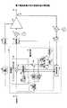
図8は、電力増幅装置の第3実施形態の構成図を示す。図8において図2と同一部分には同一符号を付す。<Third Embodiment>
FIG. 8 shows a configuration diagram of a third embodiment of the power amplifying device. In FIG. 8, the same parts as those in FIG.
図8において、端子21には送信信号(I,Q)が供給される。この送信信号は電圧制御部22と歪補償部23に供給される。電圧制御部22は送信信号(I,Q)の振幅[(I2+Q2)1/2]を求め、この振幅を関数Fに代入し、振幅に基づいた電圧信号を生成する。ここで、関数Fは、例えば振幅値が所定値α未満では一定値の電圧信号とし、振幅値が所定値α(αは例えば送信信号の最大振幅の数分の1程度)を超えると振幅値に比例した値の電圧信号とするような関数である。この電圧信号は遅延部24を経て電圧制御増幅器25の電源端子に供給される。In FIG. 8, a transmission signal (I, Q) is supplied to the terminal 21. This transmission signal is supplied to the
歪補償部23はプリディストーション信号生成部26と遅延制御部60と係数更新部29を有している。 The
プリディストーション信号生成部26はルックアップテーブル方式であり、アドレス生成部26aと歪補償係数テーブル(メモリ)26bと乗算器26cを有している。アドレス生成部26aは遅延制御部60内の振幅変換部40から送信信号の振幅を供給され、この送信信号の振幅及び振幅の増分から歪補償係数テーブル26bのアドレスを生成する。アドレス生成部26aで生成したアドレスで歪補償係数テーブル26bがアクセスされ、歪補償係数テーブル26bから歪補償係数が読み出される。 The predistortion
乗算器26cは(2)式を用いて、端子21から供給される送信信号x(t)に歪補償係数テーブル26bから読み出した歪補償係数h(m)を複素乗算することで、電圧制御増幅器25の歪み特性と逆の特性を与えたプリディストーション信号y(t)を生成する。ここで、mは送信信号x(t)の振幅から決定される値である。
y(t)=h(m)×x(t) …(2)The
y (t) = h (m) × x (t) (2)
なお、先の第1実施形態においても、プリディストーション信号生成部26がルックアップテーブル方式の場合は、この第3実施形態と同様に振幅変換部40から送信信号の振幅をプリディストーション信号生成部26に供給することで、振幅変換部40を共用する構成としてもよい。 In the first embodiment as well, when the predistortion
このプリディストーション信号は遅延部31を経て直交変調器32に供給され直交変調される。直交変調器32の出力する無線周波数の直交変調信号は電圧制御増幅器25の入力端子に供給される。 This predistortion signal is supplied to the
電圧制御増幅器25は電源端子に供給される電圧信号に応じて増幅特性を変化させて直交変調信号の電力増幅を行う。電圧制御増幅器25の出力信号は方向性結合器33を経て端子34より出力される。直交変調信号の一部は方向性結合器33から取り出され直交復調器35にて直交復調される。得られた復調信号(I,Q)はフィルタ36を経て係数更新部29に供給される。 The
係数更新部29は(3)式を用いて、プリディストーション信号生成部から読み出された歪補償係数と送信信号と復調信号の差分と復調信号とに基づいて歪補償係数の更新分を求める。次に、この更新分と歪補償係数生成部45から読み出された歪補償係数を加算しして新たな歪補償係数を生成する。そして生成した新たな歪補償係数をプリディストーション信号生成部26に供給して歪補償係数テーブルの歪補償係数を更新する。 The
以下に、歪補償係数h(m)の生成式を示す。ここで、x(t)は送信信号、mは送信信号x(t)の振幅から決定される値、e(t)は差分、r(t)は復調信号、μは係数、h−(m)は更新前の歪補償係数、x‘(t)は前回の送信信号である。
h(m)=h−(m)+μe(t)×x(t)
=h−(m)+μ{h−(m)×x(t)−h−(m)×x‘(t)}×x(t)
h−(m)×x‘(t)=r(t)
…(3)A generation formula of the distortion compensation coefficient h (m) is shown below. Here, x (t) is a transmission signal, m is a value determined from the amplitude of the transmission signal x (t), e (t) is a difference, r (t) is a demodulated signal, μ is a coefficient, and h− (m ) Is a distortion compensation coefficient before update, and x ′ (t) is a previous transmission signal.
h (m) = h - ( m) + μe (t) × x (t)
= H - (m) + μ {h - (m) × x (t) -h - (m) × x '(t)} × x (t)
h - (m) × x ' (t) = r (t)
... (3)
次に、遅延制御部60について説明する。遅延制御部60内の振幅変換部40は端子21から供給される送信信号の振幅[(I2+Q2)1/2]を求め、振幅判定部41に供給する。振幅判定部41は振幅値が所定値β未満で、かつ、所定値α(<β)以上の値であるか否かを判定する。ここで、所定値βは例えば送信信号の最大振幅より十分に小さい値であり、例えば送信信号の最大振幅の4/5程度の値である。振幅判定部41は振幅値が所定値β未満かつ所定値α以上であるときスイッチオン信号を生成してスイッチ62に供給する。このように、振幅値が所定値β未満の部分でスイッチオンとしているのは、電圧制御増幅器25における送信信号とプリディストーション信号とのタイミングのずれに対して、送信信号が所定値β未満の部分でプリディストーション信号の振幅が大きく変化するからである。Next, the
この実施形態では先の第1及び第2実施形態と異なり、スイッチ62にはプリディストーション信号生成部26の歪補償係数テーブル26bから読み出した歪補償係数が供給されており、スイッチ62は振幅判定部41からスイッチオン信号を供給されているときにオンする。スイッチ62はオン時に上記歪補償係数を分散算出部63に供給する。 In this embodiment, unlike the first and second embodiments, the distortion compensation coefficient read from the distortion compensation coefficient table 26b of the predistortion
分散算出部63はスイッチ62のオン時における歪補償係数の分散(所定時間分の歪補償係数についての分散)を求める。分散算出部63で得た歪補償係数の分散値は比較部44に供給されると共に、遅延部45においてフィードバック制御で歪補償係数が更新されるのに要する時間である所定時間Dだけ遅延されて比較部44に供給される。比較部44は遅延されていない歪補償係数の分散値と遅延された歪補償係数の分散値とを比較して比較結果を制御部46に供給する。制御部46は比較結果に応じて遅延部31の遅延時間を可変調整する。なお、制御部46は遅延部31の代りに遅延部24の遅延時間を可変調整する構成としても良い。 The
先に説明したように、所望の振幅より小さい電圧制御増幅器25の出力信号がフィードバックされた状態で係数更新部29によりプリディストーション信号生成部26の歪補償係数を更新すると、振幅の小さい欠損部を補うように欠損部に対応する歪補償係数が大きくなる。これにより、歪補償係数の分散値も大きくなる。 As described above, when the distortion updating coefficient of the predistortion
したがって、歪補償係数の分散値が小さくなるように遅延部31の遅延時間を可変調整することで、電圧制御増幅器25に入力される送信信号と電圧制御増幅器25に入力される電圧信号とのタイミングを一致する方向に近づけることができる。 Therefore, the timing of the transmission signal input to the
この実施形態では、振幅検出部の一例として振幅変換部40を用い、タイミング調整部の一例として遅延制御部60,遅延部31を用いている。 In this embodiment, the
<第4実施形態>
図9は、電力増幅装置の第4実施形態の構成図を示す。図9において図7と同一部分には同一符号を付す。<Fourth embodiment>
FIG. 9 shows a configuration diagram of a fourth embodiment of the power amplifying device. In FIG. 9, the same parts as those in FIG.
図9において、端子21には送信信号(I,Q)が供給される。この送信信号は電圧制御部22と歪補償部23に供給される。電圧制御部22は送信信号(I,Q)の振幅[(I2+Q2)1/2]を求め、この振幅を関数Fに代入し、振幅に基づいた電圧信号を生成する。ここで、関数Fは、例えば振幅値が所定値α未満では一定値の電圧信号とし、振幅値が所定値α(αは例えば送信信号の最大振幅の数分の1程度)を超えると振幅値に比例した値の電圧信号とするような関数である。この電圧信号は遅延部24を経て電圧制御増幅器25の電源端子に供給される。In FIG. 9, a transmission signal (I, Q) is supplied to the terminal 21. This transmission signal is supplied to the
歪補償部23はプリディストーション信号生成部26と遅延制御部70と係数更新部29を有している。 The
プリディストーション信号生成部26はルックアップテーブル方式であり、アドレス生成部26aと歪補償係数テーブル(メモリ)26bと乗算器26cを有している。アドレス生成部26aは遅延制御部60内の振幅変換部40から送信信号の振幅を供給され、この送信信号の振幅及び振幅の増分から歪補償係数テーブル26bのアドレスを生成する。アドレス生成部26aで生成したアドレスで歪補償係数テーブル26bがアクセスされ、歪補償係数テーブル26bから歪補償係数を読み出される。 The predistortion
乗算器26cは(2)式を用いて、端子21から供給される送信信号x(t)に歪補償係数テーブル26bから読み出した歪補償係数h(m)を複素乗算することで、電圧制御増幅器25の歪み特性と逆の特性を与えたプリディストーション信号y(t)を生成する。ここで、mは送信信号x(t)の振幅から決定される値である。
y(t)=h(m)×x(t) …(2)The
y (t) = h (m) × x (t) (2)
なお、先の第2実施形態においても、プリディストーション信号生成部26がルックアップテーブル方式の場合は、この第4実施形態と同様に振幅変換部40から送信信号の振幅をプリディストーション信号生成部26に供給することで、振幅変換部40を共用する構成としてもよい。 Also in the second embodiment, when the predistortion
このプリディストーション信号は遅延部31を経て直交変調器32に供給され直交変調される。直交変調器32の出力する無線周波数の直交変調信号は電圧制御増幅器25の入力端子に供給される。 This predistortion signal is supplied to the
電圧制御増幅器25は電源端子に供給される電圧信号に応じて増幅特性を変化させて直交変調信号の電力増幅を行う。電圧制御増幅器25の出力信号は方向性結合器33を経て端子34より出力される。直交変調信号の一部は方向性結合器33から取り出され直交復調器35にて直交復調される。得られた復調信号(I,Q)はフィルタ36を経て係数更新部29に供給される。 The
係数更新部29は(3)式を用いて、プリディストーション信号生成部から読み出された歪補償係数と送信信号と復調信号の差分と復調信号とに基づいて歪補償係数の更新分を求める。次に、この更新分と歪補償係数生成部45から読み出された歪補償係数を加算しして新たな歪補償係数を生成する。そして生成した新たな歪補償係数をプリディストーション信号生成部26に供給して歪補償係数テーブルの歪補償係数を更新する。 The
以下に、歪補償係数h(m)の生成式を示す。ここで、x(t)は送信信号、mは送信信号x(t)の振幅から決定される値、e(t)は差分、r(t)は復調信号、μは係数、h−(m)は更新前の歪補償係数、x‘(t)は前回の送信信号である。
h(m)=h−(m)+μe(t)×x(t)
=h−(m)+μ{h−(m)×x(t)−h−(m)×x‘(t)}×x(t)
h−(m)×x‘(t)=r(t)
…(3)A generation formula of the distortion compensation coefficient h (m) is shown below. Here, x (t) is a transmission signal, m is a value determined from the amplitude of the transmission signal x (t), e (t) is a difference, r (t) is a demodulated signal, μ is a coefficient, and h− (m ) Is a distortion compensation coefficient before update, and x ′ (t) is a previous transmission signal.
h (m) = h - ( m) + μe (t) × x (t)
= H - (m) + μ {h - (m) × x (t) -h - (m) × x '(t)} × x (t)
h - (m) × x ' (t) = r (t)
... (3)
次に、遅延制御部70について説明する。遅延制御部70内の振幅変換部40は端子21から供給される送信信号の振幅[(I2+Q2)1/2]を求め、振幅判定部41及び傾き算出部51に供給する。振幅判定部41は振幅値が所定値β未満で、かつ、所定値α(<β)以上の値であるか否かを判定する。ここで、所定値βは例えば送信信号の最大振幅より十分に小さい値であり、例えば送信信号の最大振幅の4/5程度の値である。振幅判定部41は振幅値が所定値β未満かつ所定値α以上であるときスイッチオン信号を生成してスイッチ62に供給する。このように、振幅値が所定値β未満の部分でスイッチオンとしているのは、電圧制御増幅器25における送信信号とプリディストーション信号とのタイミングのずれに対して、送信信号が所定値β未満の部分でプリディストーション信号の振幅が大きく変化するからである。Next, the
傾き算出部51は、送信信号の振幅が増大する傾きが正(+)の状態か、又は、送信信号の振幅が減少する傾きが負(−)の状態かを判別し、判別結果を分散算出部72,73に供給する。 The
この実施形態では第3実施形態と同様に、スイッチ62にはプリディストーション信号生成部26の歪補償係数テーブル26bから読み出した歪補償係数が供給されており、スイッチ62は振幅判定部41からスイッチオン信号を供給されているときにオンする。スイッチ62はオン時に上記歪補償係数を分散算出部72,73に供給する。 In this embodiment, as in the third embodiment, the distortion compensation coefficient read from the distortion compensation coefficient table 26 b of the predistortion
分散算出部72は、傾きが正の場合にのみ、スイッチ42のオン時における歪補償係数の分散を求める。分散算出部73は、傾きが負の場合にのみ、スイッチ42のオン時における歪補償係数の分散を求める。分散算出部72,73それぞれで得た歪補償係数の分散値は比較部54に供給される。 The
ところで、図4(B)に示す出力信号の振幅の傾きが正の部分においてプリディストーション信号に図5(A)に示す突出部c1〜c5が発生して、傾きが正の部分において歪補償係数の分散値が大きくなった場合には、遅延部31の遅延時間を小さくする方向に変更すれば良い。 By the way, the projections c1 to c5 shown in FIG. 5A are generated in the predistortion signal in the portion where the amplitude gradient of the output signal shown in FIG. 4B is positive, and the distortion compensation coefficient is shown in the portion where the inclination is positive. When the variance value of becomes larger, the delay time of the
また、図4(C)に示す出力信号の振幅の傾きが負の部分においてプリディストーション信号は図5(B)に示すように突出部d1〜d5が発生して、傾きが負の部分において歪補償係数の分散値が大きくなった場合には、遅延部31の遅延時間を大きくする方向に変更すれば良い。 4C, the predistortion signal has protrusions d1 to d5 as shown in FIG. 5B in the portion where the amplitude gradient of the output signal is negative, and distortion occurs in the portion where the inclination is negative. When the dispersion value of the compensation coefficient is increased, the delay time of the
比較部54は分散算出部72,73それぞれで得た歪補償係数の分散値のうち値が大きい方の傾きの極性(分散算出部72ならば正、分散算出部73ならば負)を選択して制御部55に供給する。 The
制御部55は傾きの極性が正であれば遅延部31の遅延時間を微少時間Δtだけ短縮する調整を行う。また、傾きの極性が負であれば遅延部31の遅延時間を微少時間Δtだけ延長する調整を行う。なお、制御部55は遅延部31の代りに遅延部24の遅延時間を可変調整する構成としても良い。 If the polarity of the slope is positive, the
制御部55が処理を繰り返すことで、平均振幅値が最小となる歪補償係数を生成できる。したがって、温度変化や経年変化の影響によらず、電圧制御増幅器における電圧信号と送信信号のタイミングのずれを低減することができる。この実施形態では傾きの極性から遅延時間を調整する方向が分かるため、調整時間を短縮することができる。 When the
なお、上記実施形態ではルックアップテーブル方式のプリディストーション信号生成部26を用いているが、これに代えて、級数型歪補償方式のプリディストーション信号生成部を用いても良い。 In the above-described embodiment, the look-up table type predistortion
この実施形態では、振幅検出部の一例として振幅変換部40を用い、タイミング調整部の一例として遅延制御部70,遅延部31を用い、傾き検出部の一例として傾き算出部51を用いている。 In this embodiment, the
<第5実施形態>
図10は、電力増幅装置の第5実施形態の構成図を示す。図10において図2と同一部分には同一符号を付す。<Fifth Embodiment>
FIG. 10 shows a configuration diagram of a fifth embodiment of the power amplifying device. In FIG. 10, the same parts as those in FIG.
図10において、端子21には送信信号(I,Q)が供給される。この送信信号は電圧制御部22と歪補償部23に供給される。電圧制御部22は送信信号(I,Q)の振幅[(I2+Q2)1/2]を求め、この振幅を関数Fに代入し、振幅に基づいた電圧信号を生成する。ここで、関数Fは、例えば振幅値が所定値α未満では一定値の電圧信号とし、振幅値が所定値α(αは例えば送信信号の最大振幅の数分の1程度)を超えると振幅値に比例した値の電圧信号とするような関数である。この電圧信号は遅延部24を経て電圧制御増幅器25の電源端子に供給される。In FIG. 10, a transmission signal (I, Q) is supplied to the terminal 21. This transmission signal is supplied to the
歪補償部23はプリディストーション信号生成部26と遅延制御部27とプリディストーション信号生成部28aと減算器28bと係数更新部28cを有している。プリディストーション信号生成部26は、例えば級数型歪補償方式でプリディストーション信号を生成する。なお、プリディストーション信号生成部26としては、ルックアップテーブル方式を用いても良い。 The
このプリディストーション信号は遅延部31を経て直交変調器32に供給され直交変調される。直交変調器32の出力する無線周波数の直交変調信号は電圧制御増幅器25の入力端子に供給される。 This predistortion signal is supplied to the
電圧制御増幅器25は電源端子に供給される電圧信号に応じて増幅特性を変化させて直交変調信号の電力増幅を行う。電圧制御増幅器25の出力信号は方向性結合器33を経て端子34より出力される。直交変調信号の一部は方向性結合器33から取り出され直交復調器35にて直交復調される。得られた復調信号(I,Q)はフィルタ36を経てプリディストーション信号生成部28aに供給される。 The
プリディストーション信号生成部28aはプリディストーション信号生成部26と同一構成であり、復調信号からプリディストーション信号を生成して減算器28bに供給し、また、復調信号を係数更新部28cに供給する。減算器28bはプリディストーション信号生成部26の出力する送信信号のプリディストーション信号からプリディストーション信号生成部28aの出力する復調信号のプリディストーション信号を減算して差分を求め、係数更新部28cに供給する。係数更新部28cは(1)式を用いて歪補償係数h1〜hnを算出し、この歪補償係数h1〜hnを新たな歪補償係数としてプリディストーション信号生成部26,28aそれぞれに供給する。The predistortion
以下に、歪補償係数h1〜hnの生成式を示す。ここで、x(t)は送信信号、r(t)は復調信号、e(t)は差分、μ1〜μnは係数、nは次数である。
h1(t)=h1(t−1)+μ1e(t)r(t)
h2(t)=h2(t−1)+μ2e(t)|r(t)|r(t)
………
hn(t)=hn(t−1)+μne(t)|r(t)|(n−1)r(t)
…(1)Hereinafter, a production equation of the
h1 (t) = h1 (t−1) + μ1 e (t) r (t)
h2 (t) = h2 (t−1) + μ2 e (t) | r (t) | r (t)
………
hn (t) = hn (t−1) + μn e (t) | r (t) |(n−1) r (t)
... (1)
次に、遅延制御部90について説明する。遅延制御部90内の除算回路91は、プリディストーション信号生成部26から供給されるプリディストーション信号Aを端子21から供給される送信信号Bで除算する(A/B)。この演算により送信信号に対する歪補償係数に相当する値(A/B)を得ることができ、この歪補償係数相当値はスイッチ92に供給される。 Next, the delay control unit 90 will be described. The
振幅変換部40は端子21から供給される送信信号の振幅[(I2+Q2)1/2]を求め、振幅判定部41に供給する。振幅判定部41は振幅値が所定値β未満で、かつ、所定値α(<β)以上の値であるか否かを判定する。ここで、所定値βは例えば送信信号の最大振幅より十分に小さい値であり、例えば送信信号の最大振幅の4/5程度の値である。振幅判定部41は振幅値が所定値β未満かつ所定値α以上であるときスイッチオン信号を生成してスイッチ92に供給する。このように、振幅値が所定値β未満の部分でスイッチオンとしているのは、電圧制御増幅器25における送信信号とプリディストーション信号とのタイミングのずれに対して、送信信号が所定値β未満の部分でプリディストーション信号の振幅が大きく変化するからである。The
スイッチ92は歪補償係数相当値を供給されており、振幅判定部41からスイッチオン信号を供給されているときにオンする。スイッチ92はオン時に上記歪補償係数相当値を分散算出部93に供給する。 The switch 92 is supplied with a distortion compensation coefficient equivalent value and is turned on when a switch-on signal is supplied from the
分散算出部93はスイッチ92のオン時における歪補償係数相当値の分散(所定時間分の歪補償係数についての分散)を求める。分散算出部93で得た歪補償係数の分散値は比較部94に供給されると共に、遅延部95においてフィードバック制御で歪補償係数が更新されるのに要する時間である所定時間Dだけ遅延されて比較部94に供給される。比較部94は遅延されていない歪補償係数の分散値と遅延された歪補償係数の分散値とを比較して比較結果を制御部96に供給する。制御部96は比較結果に応じて遅延部31の遅延時間を可変調整する。なお、制御部96は遅延部31の代りに遅延部24の遅延時間を可変調整する構成としても良い。 The dispersion calculation unit 93 obtains the dispersion of the distortion compensation coefficient equivalent value (dispersion of the distortion compensation coefficient for a predetermined time) when the switch 92 is on. The dispersion value of the distortion compensation coefficient obtained by the dispersion calculation unit 93 is supplied to the comparison unit 94 and is delayed by a predetermined time D which is a time required for the distortion compensation coefficient to be updated by feedback control in the delay unit 95. It is supplied to the comparison unit 94. The comparison unit 94 compares the dispersion value of the non-delayed distortion compensation coefficient with the dispersion value of the delayed distortion compensation coefficient, and supplies the comparison result to the control unit 96. The control unit 96 variably adjusts the delay time of the
先に説明したように、所望の振幅より小さい電圧制御増幅器25の出力信号がフィードバックされた状態で係数更新部28cによりプリディストーション信号生成部26の歪補償係数を更新すると、振幅の小さい欠損部を補うように欠損部に対応する歪補償係数が大きくなる。これにより、歪補償係数相当値の分散値も大きくなる。 As described above, when the distortion compensation coefficient of the predistortion
したがって、歪補償係数相当値の分散値が小さくなるように遅延部31の遅延時間を可変調整することで、電圧制御増幅器25に入力される送信信号と電圧制御増幅器25に入力される電圧信号とのタイミングを一致する方向に近づけることができる。 Therefore, the transmission signal input to the
この実施形態では、振幅検出部の一例として振幅変換部40を用い、タイミング調整部の一例として遅延制御部90,遅延部31を用いている。 In this embodiment, the
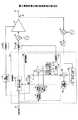
<第6実施形態>
図11は、電力増幅装置の第6実施形態の構成図を示す。図11において図2と同一部分には同一符号を付す。<Sixth Embodiment>
FIG. 11 shows a configuration diagram of a sixth embodiment of the power amplifying device. 11, the same parts as those in FIG.
図11において、端子21には送信信号(I,Q)が供給される。この送信信号は電圧制御部22と歪補償部23に供給される。電圧制御部22は送信信号(I,Q)の振幅[(I2+Q2)1/2]を求め、この振幅を関数Fに代入し、振幅に基づいた電圧信号を生成する。ここで、関数Fは、例えば振幅値が所定値α未満では一定値の電圧信号とし、振幅値が所定値α(αは例えば送信信号の最大振幅の数分の1程度)を超えると振幅値に比例した値の電圧信号とするような関数である。この電圧信号は遅延部24を経て電圧制御増幅器25の電源端子に供給される。In FIG. 11, a transmission signal (I, Q) is supplied to the terminal 21. This transmission signal is supplied to the
歪補償部23はプリディストーション信号生成部26と遅延制御部27とプリディストーション信号生成部28aと減算器28bと係数更新部28cを有している。プリディストーション信号生成部26は、例えば級数型歪補償方式でプリディストーション信号を生成する。なお、プリディストーション信号生成部26としては、ルックアップテーブル方式を用いても良い。 The
このプリディストーション信号は遅延部31を経て直交変調器32に供給され直交変調される。直交変調器32の出力する無線周波数の直交変調信号は電圧制御増幅器25の入力端子に供給される。 This predistortion signal is supplied to the
電圧制御増幅器25は電源端子に供給される電圧信号に応じて増幅特性を変化させて直交変調信号の電力増幅を行う。電圧制御増幅器25の出力信号は方向性結合器33を経て端子34より出力される。直交変調信号の一部は方向性結合器33から取り出され直交復調器35にて直交復調される。得られた復調信号(I,Q)はフィルタ36を経てプリディストーション信号生成部28aに供給される。 The
プリディストーション信号生成部28aはプリディストーション信号生成部26と同一構成であり、復調信号からプリディストーション信号を生成して減算器28bに供給し、また、復調信号を係数更新部28cに供給する。減算器28bはプリディストーション信号生成部26の出力する送信信号のプリディストーション信号からプリディストーション信号生成部28aの出力する復調信号のプリディストーション信号を減算して差分を求め、係数更新部28cに供給する。係数更新部28cは(1)式を用いて歪補償係数h1〜hnを算出し、この歪補償係数h1〜hnを新たな歪補償係数としてプリディストーション信号生成部26,28aそれぞれに供給する。The predistortion
以下に、歪補償係数h1〜hnの生成式を示す。ここで、x(t)は送信信号、r(t)は復調信号、e(t)は差分、μ1〜μnは係数、nは次数である。
h1(t)=h1(t−1)+μ1e(t)r(t)
h2(t)=h2(t−1)+μ2e(t)|r(t)|r(t)
………
hn(t)=hn(t−1)+μne(t)|r(t)|(n−1)r(t)
…(1)Hereinafter, a production equation of the
h1 (t) = h1 (t−1) + μ1 e (t) r (t)
h2 (t) = h2 (t−1) + μ2 e (t) | r (t) | r (t)
………
hn (t) = hn (t−1) + μn e (t) | r (t) |(n−1) r (t)
... (1)
次に、遅延制御部100について説明する。遅延制御部100内の除算回路91は、プリディストーション信号生成部26から供給されるプリディストーション信号Aを端子21から供給される送信信号Bで除算する(A/B)。この演算により送信信号に対する歪補償係数に相当する値(A/B)を得ることができ、この歪補償係数相当値はスイッチ92に供給される。 Next, the
振幅変換部40は端子21から供給される送信信号の振幅[(I2+Q2)1/2]を求め、振幅判定部41に供給する。振幅判定部41は振幅値が所定値β未満で、かつ、所定値α(<β)以上の値であるか否かを判定する。ここで、所定値βは例えば送信信号の最大振幅より十分に小さい値であり、例えば送信信号の最大振幅の4/5程度の値である。振幅判定部41は振幅値が所定値β未満かつ所定値α以上であるときスイッチオン信号を生成してスイッチ92に供給する。このように、振幅値が所定値β未満の部分でスイッチオンとしているのは、電圧制御増幅器25における送信信号とプリディストーション信号とのタイミングのずれに対して、送信信号が所定値β未満の部分でプリディストーション信号の振幅が大きく変化するからである。The
傾き算出部101は、送信信号の振幅が増大する傾きが正(+)の状態か、又は、送信信号の振幅が減少する傾きが負(−)の状態かを判別し、判別結果を分散算出部102,103に供給する。 The slope calculation unit 101 determines whether the slope at which the amplitude of the transmission signal increases is positive (+) or the slope at which the amplitude of the transmission signal decreases is negative (-), and calculates the dispersion of the determination results.
スイッチ92は歪補償係数相当値を供給されており、振幅判定部41からスイッチオン信号を供給されているときにオンする。スイッチ92はオン時に上記歪補償係数相当値を分散算出部102,103に供給する。 The switch 92 is supplied with a distortion compensation coefficient equivalent value and is turned on when a switch-on signal is supplied from the
分散算出部102は、傾きが正の場合にのみ、スイッチ92のオン時における補償係数相当値の分散を求める。分散算出部103は、傾きが負の場合にのみ、スイッチ92のオン時における補償係数相当値の分散を求める。分散算出部102,103それぞれで得た歪補償係数の分散値は比較部104に供給される。 The
先に説明したように、図4(B)に示す出力信号の振幅の傾きが正の部分においてプリディストーション信号に図5(A)に示す突出部c1〜c5が発生して、傾きが正の部分において歪補償係数相当値の分散値が大きくなった場合には、遅延部31の遅延時間を小さくする方向に変更すれば良い。 As described above, the protrusions c1 to c5 shown in FIG. 5A are generated in the predistortion signal in the portion where the amplitude inclination of the output signal shown in FIG. 4B is positive, and the inclination is positive. When the variance value of the distortion compensation coefficient equivalent value increases in the portion, the delay time of the
また、図4(C)に示す出力信号の振幅の傾きが負の部分においてプリディストーション信号は図5(B)に示すように突出部d1〜d5が発生して、傾きが負の部分において歪補償係数相当値の分散値が大きくなった場合には、遅延部31の遅延時間を大きくする方向に変更すれば良い。 4C, the predistortion signal has protrusions d1 to d5 as shown in FIG. 5B in the portion where the amplitude gradient of the output signal is negative, and distortion occurs in the portion where the inclination is negative. When the dispersion value corresponding to the compensation coefficient increases, the delay time of the
比較部104は分散算出部102,103それぞれで得た補償係数相当値の分散値のうち値が大きい方の傾きの極性(分散算出部102ならば正、分散算出部103ならば負)を選択して制御部105に供給する。 The
制御部105は傾きの極性が正であれば遅延部31の遅延時間を微少時間Δtだけ短縮する調整を行う。また、傾きの極性が負であれば遅延部31の遅延時間を微少時間Δtだけ延長する調整を行う。なお、制御部105は遅延部31の代りに遅延部24の遅延時間を可変調整する構成としても良い。 If the polarity of the slope is positive, the
制御部105が処理を繰り返すことで、平均振幅値が最小となる歪補償係数を生成できる。したがって、温度変化や経年変化の影響によらず、電圧制御増幅器における電圧信号と送信信号のタイミングのずれを低減することができる。この実施形態では傾きの極性から遅延時間を調整する方向が分かるため、調整時間を短縮することができる。 When the
なお、上記実施形態では級数型歪補償方式のプリディストーション信号生成部26を用いているが、これに代えて、ルックアップテーブル方式のプリディストーション信号生成部を用いても良い。 Although the series distortion compensation type predistortion
この実施形態では、振幅検出部の一例として振幅変換部40を用い、タイミング調整部の一例として遅延制御部100,遅延部31を用い、傾き検出部の一例として傾き算出部101を用いている。
(付記1)
増幅器と、前記増幅器に供給する電圧信号を送信信号に応じて制御する電圧制御部と、前記送信信号に前記増幅器の入力対出力特性の逆特性を予め与えて歪補償処理を行う歪補償部とを備え、前記歪補償部の出力信号を前記増幅器に入力して増幅する電力増幅装置であって、
前記送信信号の振幅を検出する振幅検出部と、
前記送信信号の振幅の検出値が所定値未満のときの、前記送信信号に対する前記歪補償部の出力信号の振幅を低減するように、前記歪補償部の出力信号と前記電圧信号のタイミングを調整するタイミング調整部と、
を備えることを特徴とする電力増幅装置。
(付記2)
前記送信信号の傾き情報を検出する傾き検出部を備え、
前記タイミング調整部は、前記傾き情報に応じて前記タイミングを調整する方向を決定することを特徴とする付記1に記載の電力増幅装置。
(付記3)
増幅器と、前記増幅器に供給する電圧信号を送信信号に応じて制御する電圧制御部と、前記増幅器の入力対出力特性の逆特性に応じた一又は複数の歪補償係数を用いた演算を前記送信信号に予め行う歪補償処理を実行する歪補償部とを備え、前記歪補償部の出力信号を前記増幅器に入力して増幅する電力増幅装置であって、
前記歪補償部の出力信号と、前記増幅器の出力のフィードバック信号とに基づいて、前記一又は複数の歪補償係数を逐次更新する係数更新部と、
前記送信信号の振幅を検出する振幅検出部と、
前記送信信号の振幅の検出値が所定値未満のときの、前記送信信号に対する前記一又は複数の歪補償係数の分散を低減するように、前記歪補償部の出力信号と前記電圧信号のタイミングを調整するタイミング調整部と、
を備えることを特徴とする電力増幅装置。
(付記4)
前記タイミング調整部は、前記歪補償部の出力信号を前記送信信号で除算した値を、前記送信信号に対する歪補償係数に相当する値として、前記歪補償係数の分散を算出することを特徴とする付記3に記載の電力増幅装置。
(付記5)
前記送信信号の傾き情報を検出する傾き検出部を備え、
前記タイミング調整部は、前記送信信号の振幅の検出値が所定値未満かつ前記歪補償係数の分散が増加するときの、前記送信信号の傾き情報に応じて、前記タイミングを調整する方向を決定することを特徴とする付記3又は4に記載の電力増幅装置。
(付記6)
増幅器に供給する電圧信号を送信信号に応じて制御する電圧制御ステップと、前記送信信号に前記増幅器の入力対出力特性の逆特性を予め与える歪補償ステップと、前記歪補償ステップの出力信号を前記増幅器に入力して増幅する電力増幅ステップとを含む電力増幅方法であって、
前記送信信号の振幅を検出する振幅検出ステップと、
前記送信信号の振幅の検出値が所定値未満のときの、前記送信信号に対する前記歪補償部の出力信号の振幅を低減するように、前記歪補償部の出力信号と前記電圧信号のタイミングを調整するタイミング調整ステップと、
を含むことを特徴とする電力増幅方法。
(付記7)
増幅器に供給する電圧信号を送信信号に応じて制御する電圧制御ステップと、前記増幅器の入力対出力特性の逆特性に応じた一又は複数の歪補償係数を用いた演算を前記送信信号に予め行う歪補償ステップと、前記歪補償ステップの出力信号を前記増幅器に入力して増幅する電力増幅ステップとを含む電力増幅方法であって、
前記歪補償部の出力信号と、前記増幅器の出力のフィードバック信号とに基づいて、前記一又は複数の歪補償係数を逐次更新する係数更新ステップと、
前記送信信号の振幅を検出する振幅検出ステップと、
前記送信信号の振幅の検出値が所定値未満のときの、前記送信信号に対する前記一又は複数の歪補償係数の分散を低減するように、前記歪補償部の出力信号と前記電圧信号のタイミングを調整するタイミング調整ステップと、
を含むことを特徴とする電力増幅方法。
(付記8)
前記送信信号の傾き情報を検出する傾き検出ステップを含み、
前記タイミング調整ステップは、前記傾き情報に応じて前記タイミングを調整する方向を決定することを特徴とする付記6に記載の電力増幅方法。
(付記9)
前記送信信号の傾き情報を検出する傾き検出ステップを含み、
前記タイミング調整ステップは、前記送信信号の振幅の検出値が所定値未満かつ前記歪補償係数の分散が増加するときの、前記送信信号の傾き情報に応じて、前記タイミングを調整する方向を決定することを特徴とする付記7に記載の電力増幅方法。In this embodiment, the
(Appendix 1)
An amplifier, a voltage control unit that controls a voltage signal supplied to the amplifier according to a transmission signal, and a distortion compensation unit that performs distortion compensation processing by previously giving an inverse characteristic of the input-output characteristic of the amplifier to the transmission signal. A power amplifying apparatus for inputting and amplifying the output signal of the distortion compensation unit to the amplifier,
An amplitude detector for detecting the amplitude of the transmission signal;
The timing of the output signal of the distortion compensation unit and the voltage signal is adjusted so as to reduce the amplitude of the output signal of the distortion compensation unit with respect to the transmission signal when the detected value of the amplitude of the transmission signal is less than a predetermined value. A timing adjustment unit,
A power amplifying apparatus comprising:
(Appendix 2)
An inclination detector for detecting inclination information of the transmission signal;
The power amplifying apparatus according to
(Appendix 3)
An amplifier, a voltage controller for controlling a voltage signal supplied to the amplifier according to a transmission signal, and an operation using one or a plurality of distortion compensation coefficients according to an inverse characteristic of an input-output characteristic of the amplifier. A power amplifying apparatus that includes a distortion compensation unit that performs distortion compensation processing performed on a signal in advance, and that amplifies the output signal of the distortion compensation unit by inputting the signal to the amplifier;
A coefficient updating unit that sequentially updates the one or more distortion compensation coefficients based on the output signal of the distortion compensation unit and the feedback signal of the output of the amplifier;
An amplitude detector for detecting the amplitude of the transmission signal;
When the detected value of the amplitude of the transmission signal is less than a predetermined value, the timing of the output signal of the distortion compensation unit and the voltage signal is reduced so as to reduce dispersion of the one or more distortion compensation coefficients with respect to the transmission signal. A timing adjustment unit to adjust;
A power amplifying apparatus comprising:
(Appendix 4)
The timing adjustment unit calculates a variance of the distortion compensation coefficient using a value obtained by dividing the output signal of the distortion compensation unit by the transmission signal as a value corresponding to a distortion compensation coefficient for the transmission signal. The power amplification device according to
(Appendix 5)
An inclination detector for detecting inclination information of the transmission signal;
The timing adjustment unit determines a direction in which the timing is adjusted according to inclination information of the transmission signal when a detected value of an amplitude of the transmission signal is less than a predetermined value and dispersion of the distortion compensation coefficient increases. The power amplifying device according to
(Appendix 6)
A voltage control step for controlling a voltage signal supplied to the amplifier in accordance with a transmission signal; a distortion compensation step for preliminarily giving an inverse characteristic of the input-to-output characteristic of the amplifier to the transmission signal; and an output signal of the distortion compensation step. A power amplifying method including a power amplifying step for amplifying by inputting to an amplifier,
An amplitude detection step of detecting the amplitude of the transmission signal;
The timing of the output signal of the distortion compensation unit and the voltage signal is adjusted so as to reduce the amplitude of the output signal of the distortion compensation unit with respect to the transmission signal when the detected value of the amplitude of the transmission signal is less than a predetermined value. Timing adjustment step,
A power amplification method comprising:
(Appendix 7)
A voltage control step for controlling the voltage signal supplied to the amplifier according to the transmission signal, and an operation using one or a plurality of distortion compensation coefficients corresponding to the inverse characteristics of the input-to-output characteristics of the amplifier are performed in advance on the transmission signal. A power amplification method including a distortion compensation step, and a power amplification step of amplifying the output signal of the distortion compensation step by inputting to the amplifier,
A coefficient updating step of sequentially updating the one or more distortion compensation coefficients based on the output signal of the distortion compensation unit and the feedback signal of the output of the amplifier;
An amplitude detection step of detecting the amplitude of the transmission signal;
When the detected value of the amplitude of the transmission signal is less than a predetermined value, the timing of the output signal of the distortion compensation unit and the voltage signal is reduced so as to reduce dispersion of the one or more distortion compensation coefficients with respect to the transmission signal. A timing adjustment step to adjust;
A power amplification method comprising:
(Appendix 8)
Including an inclination detection step of detecting inclination information of the transmission signal;
The power amplification method according to
(Appendix 9)
Including an inclination detection step of detecting inclination information of the transmission signal;
The timing adjustment step determines a direction in which the timing is adjusted according to inclination information of the transmission signal when a detected value of the amplitude of the transmission signal is less than a predetermined value and dispersion of the distortion compensation coefficient increases. The power amplification method according to appendix 7, wherein:
22 電圧制御部
23 歪補償部
24,31,45 遅延部
25 電圧制御増幅器
26,28a プリディストーション信号生成部
27,50,60,70,90,100 遅延制御部
28b 減算器
28c 係数更新部
29 係数更新部
32 直交変調器
33 方向性結合器
35 直交復調器
36 フィルタ
40 振幅変換部
41 振幅判定部
42,62 スイッチ
43 平均振幅部
44,54 比較部
46,55 制御部
51 傾き算出部
52,53 平均振幅部
63,72,73 分散算出部22
Claims (7)
Translated fromJapanese前記送信信号の振幅を検出する振幅検出部と、
前記送信信号の振幅の検出値が前記送信信号の最大振幅より十分に小さい値の所定値未満のときの、前記送信信号に対する前記歪補償部の出力信号の振幅を低減するように、前記歪補償部の出力信号と前記電圧信号のタイミングを調整するタイミング調整部と、
を備えることを特徴とする電力増幅装置。An amplifier, a voltage control unit that controls a voltage signal supplied to the amplifier according to a transmission signal, and a distortion compensation unit that performs distortion compensation processing by previously giving an inverse characteristic of the input-output characteristic of the amplifier to the transmission signal. A power amplifying apparatus for inputting and amplifying the output signal of the distortion compensation unit to the amplifier,
An amplitude detector for detecting the amplitude of the transmission signal;
When the detected value of the amplitude of thetransmission signal is less than a predetermined valuethat is sufficiently smaller than the maximum amplitude of the transmission signal, the distortion compensation is performed so as to reduce the amplitude of the output signal of the distortion compensation unit with respect to the transmission signal. A timing adjustment unit for adjusting the timing of the output signal of the unit and the voltage signal;
A power amplifying apparatus comprising:
前記タイミング調整部は、前記傾き情報に応じて前記タイミングを調整する方向を決定することを特徴とする請求項1に記載の電力増幅装置。An inclination detector for detecting inclination information of the transmission signal;
The power amplifying apparatus according to claim 1, wherein the timing adjustment unit determines a direction in which the timing is adjusted according to the inclination information.
前記歪補償部の出力信号と、前記増幅器の出力のフィードバック信号とに基づいて、前記一又は複数の歪補償係数を逐次更新する係数更新部と、
前記送信信号の振幅を検出する振幅検出部と、
前記送信信号の振幅の検出値が所定値未満のときの、前記送信信号に対する前記一又は複数の歪補償係数の分散を低減するように、前記歪補償部の出力信号と前記電圧信号のタイミングを調整するタイミング調整部と、
を備えることを特徴とする電力増幅装置。An amplifier, a voltage controller for controlling a voltage signal supplied to the amplifier according to a transmission signal, and an operation using one or a plurality of distortion compensation coefficients according to an inverse characteristic of an input-output characteristic of the amplifier. A power amplifying apparatus that includes a distortion compensation unit that performs distortion compensation processing performed on a signal in advance, and that amplifies the output signal of the distortion compensation unit by inputting the signal to the amplifier;
A coefficient updating unit that sequentially updates the one or more distortion compensation coefficients based on the output signal of the distortion compensation unit and the feedback signal of the output of the amplifier;
An amplitude detector for detecting the amplitude of the transmission signal;
When the detected value of the amplitude of the transmission signal is less than a predetermined value, the timing of the output signal of the distortion compensation unit and the voltage signal is reduced so as to reduce dispersion of the one or more distortion compensation coefficients with respect to the transmission signal. A timing adjustment unit to adjust;
A power amplifying apparatus comprising:
前記タイミング調整部は、前記送信信号の振幅の検出値が所定値未満かつ前記歪補償係数の分散が増加するときの、前記送信信号の傾き情報に応じて、前記タイミングを調整する方向を決定することを特徴とする請求項3又は4に記載の電力増幅装置。An inclination detector for detecting inclination information of the transmission signal;
The timing adjustment unit determines a direction in which the timing is adjusted according to inclination information of the transmission signal when a detected value of an amplitude of the transmission signal is less than a predetermined value and dispersion of the distortion compensation coefficient increases. The power amplifying device according to claim 3 or 4, wherein
前記送信信号の振幅を検出する振幅検出ステップと、
前記送信信号の振幅の検出値が前記送信信号の最大振幅より十分に小さい値の所定値未満のときの、前記送信信号に対する前記歪補償部の出力信号の振幅を低減するように、前記歪補償部の出力信号と前記電圧信号のタイミングを調整する遅延制御ステップと、
を含むことを特徴とする電力増幅方法。A voltage control step for controlling a voltage signal supplied to the amplifier in accordance with a transmission signal; a distortion compensation step for preliminarily giving an inverse characteristic of the input-to-output characteristic of the amplifier to the transmission signal; and an output signal of the distortion compensation step. A power amplifying method including a power amplifying step for amplifying by inputting to an amplifier,
An amplitude detection step of detecting the amplitude of the transmission signal;
When the detected value of the amplitude of thetransmission signal is less than a predetermined valuethat is sufficiently smaller than the maximum amplitude of the transmission signal, the distortion compensation is performed so as to reduce the amplitude of the output signal of the distortion compensation unit with respect to the transmission signal. A delay control step of adjusting the timing of the output signal of the unit and the voltage signal;
A power amplification method comprising:
前記歪補償部の出力信号と、前記増幅器の出力のフィードバック信号とに基づいて、前記一又は複数の歪補償係数を逐次更新する係数更新ステップと、
前記送信信号の振幅を検出する振幅検出ステップと、
前記送信信号の振幅の検出値が所定値未満のときの、前記送信信号に対する前記一又は複数の歪補償係数の分散を低減するように、前記歪補償部の出力信号と前記電圧信号のタイミングを調整するタイミング調整ステップと、
を含むことを特徴とする電力増幅方法。A voltage control step for controlling the voltage signal supplied to the amplifier according to the transmission signal, and an operation using one or a plurality of distortion compensation coefficients corresponding to the inverse characteristics of the input-to-output characteristics of the amplifier are performed in advance on the transmission signal. A power amplification method including a distortion compensation step, and a power amplification step of amplifying the output signal of the distortion compensation step by inputting to the amplifier,
A coefficient updating step of sequentially updating the one or more distortion compensation coefficients based on the output signal of the distortion compensation unit and the feedback signal of the output of the amplifier;
An amplitude detection step of detecting the amplitude of the transmission signal;
When the detected value of the amplitude of the transmission signal is less than a predetermined value, the timing of the output signal of the distortion compensation unit and the voltage signal is reduced so as to reduce dispersion of the one or more distortion compensation coefficients with respect to the transmission signal. A timing adjustment step to adjust;
A power amplification method comprising:
Priority Applications (5)
| Application Number | Priority Date | Filing Date | Title |
|---|---|---|---|
| JP2009068422AJP5152059B2 (en) | 2009-03-19 | 2009-03-19 | Power amplification device and power amplification method |
| EP10155084AEP2230758B1 (en) | 2009-03-19 | 2010-03-01 | Power amplifying device and power amplifying method |
| US12/720,269US8532223B2 (en) | 2009-03-19 | 2010-03-09 | Power amplifying device and power amplifying method |
| KR1020100024112AKR101099319B1 (en) | 2009-03-19 | 2010-03-18 | Power amplifying device and power amplifying method |
| CN2010101428742ACN101841305B (en) | 2009-03-19 | 2010-03-18 | Power amplifying device and power amplifying method |
Applications Claiming Priority (1)
| Application Number | Priority Date | Filing Date | Title |
|---|---|---|---|
| JP2009068422AJP5152059B2 (en) | 2009-03-19 | 2009-03-19 | Power amplification device and power amplification method |
Publications (2)
| Publication Number | Publication Date |
|---|---|
| JP2010226198A JP2010226198A (en) | 2010-10-07 |
| JP5152059B2true JP5152059B2 (en) | 2013-02-27 |
Family
ID=42313499
Family Applications (1)
| Application Number | Title | Priority Date | Filing Date |
|---|---|---|---|
| JP2009068422AExpired - Fee RelatedJP5152059B2 (en) | 2009-03-19 | 2009-03-19 | Power amplification device and power amplification method |
Country Status (5)
| Country | Link |
|---|---|
| US (1) | US8532223B2 (en) |
| EP (1) | EP2230758B1 (en) |
| JP (1) | JP5152059B2 (en) |
| KR (1) | KR101099319B1 (en) |
| CN (1) | CN101841305B (en) |
Families Citing this family (8)
| Publication number | Priority date | Publication date | Assignee | Title |
|---|---|---|---|---|
| JP5482561B2 (en)* | 2010-08-13 | 2014-05-07 | 富士通株式会社 | Distortion compensation amplification apparatus and distortion compensation method |
| KR101213778B1 (en)* | 2011-01-11 | 2012-12-18 | (주)펄서스 테크놀러지 | Variable voltage digital audio amplication apparatus for noise compensation and method thereof |
| GB2491188A (en)* | 2011-05-27 | 2012-11-28 | Nujira Ltd | Timing alignment in a polar transmitter |
| US9202176B1 (en)* | 2011-08-08 | 2015-12-01 | Gravity.Com, Inc. | Entity analysis system |
| GB2514388A (en) | 2013-05-22 | 2014-11-26 | Nujira Ltd | Delay adjustment |
| US9893684B2 (en) | 2015-02-15 | 2018-02-13 | Skyworks Solutions, Inc. | Radio-frequency power amplifiers driven by boost converter |
| JP2016149743A (en) | 2015-02-15 | 2016-08-18 | スカイワークス ソリューションズ, インコーポレイテッドSkyworks Solutions, Inc. | Power amplifier reduced in size through elimination of matching network |
| CN105743446B (en)* | 2016-01-28 | 2018-12-18 | 芯海科技(深圳)股份有限公司 | A kind of drift voltage correcting circuit for instrument amplifier |
Family Cites Families (17)
| Publication number | Priority date | Publication date | Assignee | Title |
|---|---|---|---|---|
| JP3451947B2 (en)* | 1998-07-03 | 2003-09-29 | 住友電気工業株式会社 | OFDM modulator |
| US6646501B1 (en)* | 2002-06-25 | 2003-11-11 | Nortel Networks Limited | Power amplifier configuration |
| US7263135B2 (en)* | 2002-10-03 | 2007-08-28 | Matsushita Electric Industrial Co., Ltd. | Transmitting method and transmitter apparatus |
| JP3985649B2 (en)* | 2002-10-03 | 2007-10-03 | 松下電器産業株式会社 | Transmission method and transmission apparatus |
| WO2005027342A1 (en)* | 2003-09-15 | 2005-03-24 | Nortel Networks Limited | Power amplifier with improved linearity and efficiency |
| JP2005269440A (en)* | 2004-03-19 | 2005-09-29 | Matsushita Electric Ind Co Ltd | Polar modulation transmitter and polar modulation method |
| JP4767583B2 (en) | 2004-06-29 | 2011-09-07 | パナソニック株式会社 | Distortion compensation circuit |
| US7135918B1 (en)* | 2004-10-22 | 2006-11-14 | Nortel Networks Limited | Linear power amplifier circuit with a modulated power supply signal |
| US7715808B2 (en)* | 2005-04-28 | 2010-05-11 | Panasonic Corporation | Polar modulating circuit, polar coordinate modulating method, integrated circuit and radio transmission device |
| JP2006333450A (en)* | 2005-04-28 | 2006-12-07 | Matsushita Electric Ind Co Ltd | Polar coordinate modulation circuit, polar coordinate modulation method, integrated circuit, and wireless transmission device |
| EP1746720B1 (en)* | 2005-07-21 | 2008-04-16 | Alcatel Lucent | Adaptive Digital Pre-Distortion System |
| JP2007150786A (en)* | 2005-11-29 | 2007-06-14 | Sony Corp | Transmission/reception system, information processing apparatus and information processing method, and program |
| JP4951238B2 (en)* | 2005-12-27 | 2012-06-13 | パナソニック株式会社 | Polar coordinate modulation transmission apparatus, adaptive distortion compensation processing system, polar modulation transmission method, and adaptive distortion compensation processing method |
| JP5049562B2 (en)* | 2006-11-17 | 2012-10-17 | 株式会社日立国際電気 | Power amplifier |
| FI20065783A0 (en)* | 2006-12-08 | 2006-12-08 | Nokia Corp | Signal pre-distortion in radio transmitters |
| KR101201911B1 (en)* | 2007-10-10 | 2012-11-20 | 삼성전자주식회사 | Apparatus and method for power amplifier with delay control in wireless communication system |
| US7602244B1 (en)* | 2007-11-27 | 2009-10-13 | Nortel Networks Limited | Power amplifier bias synchronization |
- 2009
- 2009-03-19JPJP2009068422Apatent/JP5152059B2/ennot_activeExpired - Fee Related
- 2010
- 2010-03-01EPEP10155084Apatent/EP2230758B1/ennot_activeNot-in-force
- 2010-03-09USUS12/720,269patent/US8532223B2/ennot_activeExpired - Fee Related
- 2010-03-18KRKR1020100024112Apatent/KR101099319B1/ennot_activeExpired - Fee Related
- 2010-03-18CNCN2010101428742Apatent/CN101841305B/ennot_activeExpired - Fee Related
Also Published As
| Publication number | Publication date |
|---|---|
| EP2230758A1 (en) | 2010-09-22 |
| US8532223B2 (en) | 2013-09-10 |
| CN101841305A (en) | 2010-09-22 |
| JP2010226198A (en) | 2010-10-07 |
| EP2230758B1 (en) | 2013-01-23 |
| KR20100105487A (en) | 2010-09-29 |
| US20100237937A1 (en) | 2010-09-23 |
| CN101841305B (en) | 2013-01-16 |
| KR101099319B1 (en) | 2011-12-26 |
Similar Documents
| Publication | Publication Date | Title |
|---|---|---|
| JP5152059B2 (en) | Power amplification device and power amplification method | |
| JP4863729B2 (en) | Distortion compensation apparatus and distortion compensation method | |
| JP4617265B2 (en) | Distortion compensation apparatus and distortion compensation method | |
| JP6580488B2 (en) | Linearization circuit and method for a multi-level power amplifier system | |
| CN107093987B (en) | Envelope tracking system and related mobile communication device and storage medium | |
| JP4326673B2 (en) | Method for starting communication apparatus having nonlinear distortion compensation apparatus | |
| US8472556B2 (en) | Amplifier device and predistortion control method | |
| JP2010157898A (en) | Distortion compensating apparatus and distortion compensating method | |
| JP2010016821A (en) | Baseband predistortion device and method | |
| JP2002100940A (en) | Distortion compensation amplifier | |
| JP5124655B2 (en) | Distortion compensation amplifier | |
| JP2010183310A (en) | Predistorter and method for adjusting delay of the same | |
| JP6209925B2 (en) | Distortion compensation apparatus and distortion compensation method | |
| JP2015026968A (en) | Distortion compensation device and distortion compensation method | |
| JP2001111438A (en) | Transmitter and distortion compensation method to be used for the transmitter | |
| JP5630327B2 (en) | Transmitting apparatus and distortion compensation method | |
| JP2008172544A (en) | Distortion compensation circuit using diode linearizer | |
| JP4043824B2 (en) | Nonlinear distortion compensation apparatus and nonlinear distortion compensation method | |
| JP2007221613A (en) | Distortion compensation method and apparatus | |
| US7418058B2 (en) | Distortion compensating apparatus and method | |
| JP4127116B2 (en) | Nonlinear distortion compensation transmitter and compensation data update method | |
| JP2002176321A (en) | Method of correcting transmission signal distortion in wireless device and wireless device having distortion correction function | |
| JP2024039898A (en) | distortion compensator | |
| JP2021132253A (en) | Wireless communication device and coefficient update method | |
| JP2024146113A (en) | Radio stations and radio systems |
Legal Events
| Date | Code | Title | Description |
|---|---|---|---|
| A621 | Written request for application examination | Free format text:JAPANESE INTERMEDIATE CODE: A621 Effective date:20111107 | |
| A977 | Report on retrieval | Free format text:JAPANESE INTERMEDIATE CODE: A971007 Effective date:20120720 | |
| A131 | Notification of reasons for refusal | Free format text:JAPANESE INTERMEDIATE CODE: A131 Effective date:20120731 | |
| A521 | Written amendment | Free format text:JAPANESE INTERMEDIATE CODE: A523 Effective date:20120928 | |
| TRDD | Decision of grant or rejection written | ||
| A01 | Written decision to grant a patent or to grant a registration (utility model) | Free format text:JAPANESE INTERMEDIATE CODE: A01 Effective date:20121106 | |
| A61 | First payment of annual fees (during grant procedure) | Free format text:JAPANESE INTERMEDIATE CODE: A61 Effective date:20121119 | |
| FPAY | Renewal fee payment (event date is renewal date of database) | Free format text:PAYMENT UNTIL: 20151214 Year of fee payment:3 | |
| R150 | Certificate of patent or registration of utility model | Ref document number:5152059 Country of ref document:JP Free format text:JAPANESE INTERMEDIATE CODE: R150 Free format text:JAPANESE INTERMEDIATE CODE: R150 | |
| LAPS | Cancellation because of no payment of annual fees |