JP5149798B2 - Chemical liquid filling and injection system and chemical liquid filling apparatus - Google Patents
Chemical liquid filling and injection system and chemical liquid filling apparatusDownload PDFInfo
- Publication number
- JP5149798B2 JP5149798B2JP2008523761AJP2008523761AJP5149798B2JP 5149798 B2JP5149798 B2JP 5149798B2JP 2008523761 AJP2008523761 AJP 2008523761AJP 2008523761 AJP2008523761 AJP 2008523761AJP 5149798 B2JP5149798 B2JP 5149798B2
- Authority
- JP
- Japan
- Prior art keywords
- chemical
- filling
- chemical solution
- syringe
- data
- Prior art date
- Legal status (The legal status is an assumption and is not a legal conclusion. Google has not performed a legal analysis and makes no representation as to the accuracy of the status listed.)
- Expired - Fee Related
Links
Images


Classifications
- A—HUMAN NECESSITIES
- A61—MEDICAL OR VETERINARY SCIENCE; HYGIENE
- A61M—DEVICES FOR INTRODUCING MEDIA INTO, OR ONTO, THE BODY; DEVICES FOR TRANSDUCING BODY MEDIA OR FOR TAKING MEDIA FROM THE BODY; DEVICES FOR PRODUCING OR ENDING SLEEP OR STUPOR
- A61M5/00—Devices for bringing media into the body in a subcutaneous, intra-vascular or intramuscular way; Accessories therefor, e.g. filling or cleaning devices, arm-rests
- A61M5/14—Infusion devices, e.g. infusing by gravity; Blood infusion; Accessories therefor
- A61M5/142—Pressure infusion, e.g. using pumps
- A61M5/145—Pressure infusion, e.g. using pumps using pressurised reservoirs, e.g. pressurised by means of pistons
- A61M5/1452—Pressure infusion, e.g. using pumps using pressurised reservoirs, e.g. pressurised by means of pistons pressurised by means of pistons
- A61M5/14546—Front-loading type injectors
- A—HUMAN NECESSITIES
- A61—MEDICAL OR VETERINARY SCIENCE; HYGIENE
- A61M—DEVICES FOR INTRODUCING MEDIA INTO, OR ONTO, THE BODY; DEVICES FOR TRANSDUCING BODY MEDIA OR FOR TAKING MEDIA FROM THE BODY; DEVICES FOR PRODUCING OR ENDING SLEEP OR STUPOR
- A61M2205/00—General characteristics of the apparatus
- A61M2205/60—General characteristics of the apparatus with identification means
- A61M2205/6018—General characteristics of the apparatus with identification means providing set-up signals for the apparatus configuration
- A—HUMAN NECESSITIES
- A61—MEDICAL OR VETERINARY SCIENCE; HYGIENE
- A61M—DEVICES FOR INTRODUCING MEDIA INTO, OR ONTO, THE BODY; DEVICES FOR TRANSDUCING BODY MEDIA OR FOR TAKING MEDIA FROM THE BODY; DEVICES FOR PRODUCING OR ENDING SLEEP OR STUPOR
- A61M2205/00—General characteristics of the apparatus
- A61M2205/60—General characteristics of the apparatus with identification means
- A61M2205/6054—Magnetic identification systems
- A—HUMAN NECESSITIES
- A61—MEDICAL OR VETERINARY SCIENCE; HYGIENE
- A61M—DEVICES FOR INTRODUCING MEDIA INTO, OR ONTO, THE BODY; DEVICES FOR TRANSDUCING BODY MEDIA OR FOR TAKING MEDIA FROM THE BODY; DEVICES FOR PRODUCING OR ENDING SLEEP OR STUPOR
- A61M2209/00—Ancillary equipment
- A61M2209/04—Tools for specific apparatus
- A61M2209/045—Tools for specific apparatus for filling, e.g. for filling reservoirs
- A—HUMAN NECESSITIES
- A61—MEDICAL OR VETERINARY SCIENCE; HYGIENE
- A61M—DEVICES FOR INTRODUCING MEDIA INTO, OR ONTO, THE BODY; DEVICES FOR TRANSDUCING BODY MEDIA OR FOR TAKING MEDIA FROM THE BODY; DEVICES FOR PRODUCING OR ENDING SLEEP OR STUPOR
- A61M5/00—Devices for bringing media into the body in a subcutaneous, intra-vascular or intramuscular way; Accessories therefor, e.g. filling or cleaning devices, arm-rests
- A61M5/14—Infusion devices, e.g. infusing by gravity; Blood infusion; Accessories therefor
- A61M5/142—Pressure infusion, e.g. using pumps
- A61M5/145—Pressure infusion, e.g. using pumps using pressurised reservoirs, e.g. pressurised by means of pistons
- A61M5/1452—Pressure infusion, e.g. using pumps using pressurised reservoirs, e.g. pressurised by means of pistons pressurised by means of pistons
- A61M5/1456—Pressure infusion, e.g. using pumps using pressurised reservoirs, e.g. pressurised by means of pistons pressurised by means of pistons with a replaceable reservoir comprising a piston rod to be moved into the reservoir, e.g. the piston rod is part of the removable reservoir
Landscapes
- Health & Medical Sciences (AREA)
- Vascular Medicine (AREA)
- Engineering & Computer Science (AREA)
- Anesthesiology (AREA)
- Biomedical Technology (AREA)
- Heart & Thoracic Surgery (AREA)
- Hematology (AREA)
- Life Sciences & Earth Sciences (AREA)
- Animal Behavior & Ethology (AREA)
- General Health & Medical Sciences (AREA)
- Public Health (AREA)
- Veterinary Medicine (AREA)
- Infusion, Injection, And Reservoir Apparatuses (AREA)
- Medical Preparation Storing Or Oral Administration Devices (AREA)
Description
Translated fromJapanese本発明は、薬液シリンジに薬液を充填する薬液充填装置と、薬液が充填された薬液シリンジから被験者へ薬液を注入する薬液注入装置とを有する薬液充填注入システムに関する。 The present invention relates to a chemical liquid filling and injection system including a chemical liquid filling device that fills a chemical liquid into a chemical liquid syringe and a chemical liquid injection device that injects a chemical liquid from a chemical liquid syringe filled with the chemical liquid to a subject.
医療用の画像診断装置としては、CT(Computed Tomography)スキャナ、MRI(Magnetic Resonance Imaging)装置、PET(Positron
Emission Tomography)装置、アンギオ装置、およびMRA(MR Angio)装置などがある。これらの装置を使用する際は、被験者に造影剤や生理食塩水などの薬液を注入する必要がある。そこで、薬液の注入を自動で行う種々の薬液注入装置が提案され、実用化されている。Medical diagnostic imaging apparatuses include CT (Computed Tomography) scanner, MRI (Magnetic Resonance Imaging) apparatus, PET (Positron).
Emission Tomography) apparatus, Angio apparatus, MRA (MR Angio) apparatus, and the like. When these devices are used, it is necessary to inject a medical solution such as a contrast medium or physiological saline into the subject. Accordingly, various chemical solution injection devices that automatically inject chemical solutions have been proposed and put into practical use.
薬液注入装置は、薬液シリンジが着脱自在に装着される注入ヘッドを有している。薬液シリンジには薬液が充填されており、注入ヘッドに備えられた駆動機構によって薬液シリンジのピストンをシリンダ内に押し込むことで、薬液シリンジ内の薬液を被験者に注入することができる。 The chemical liquid injector has an injection head to which a chemical syringe is detachably attached. The drug solution syringe is filled with the drug solution, and the drug solution in the drug solution syringe can be injected into the subject by pushing the piston of the drug solution syringe into the cylinder by the drive mechanism provided in the injection head.
薬液シリンジには、薬液が予め充填されているプレフィルドタイプと、被験者への注入に際して所望の薬液が充填される後充填タイプとに分けられる。後充填タイプの薬液シリンジでは、薬液シリンジへの薬液の充填は、専ら医療関係者が医療現場で行う。しかし、薬液シリンジへの薬液の充填を手作業で行うことは作業負担が多大であるので、薬液充填装置を用いて、薬液シリンジへ薬液を充填することが行われている。 A chemical syringe is divided into a prefilled type in which a chemical solution is pre-filled and a post-filling type in which a desired chemical solution is filled in injection into a subject. In the post-filling type liquid medicine syringe, the liquid medicine is filled into the liquid medicine syringe exclusively by medical personnel at the medical site. However, manually filling the chemical syringe with the chemical solution has a large work load. Therefore, the chemical syringe is filled with the chemical solution using the chemical solution filling apparatus.
従来の薬液充填装置としては、特許文献1に記載されたものが知られている。特許文献1に記載された薬液充填装置は、検査条件が入力されると、入力された検査条件に基づいて必要な薬液の量を算出し、算出された薬液の量に合わせてピストン部材を移動させる。これによって、容器から薬液シリンジへ薬液が充填される。 As a conventional chemical solution filling apparatus, the one described in Patent Document 1 is known. When the inspection condition is input, the chemical filling device described in Patent Document 1 calculates the amount of the necessary chemical based on the input inspection condition, and moves the piston member according to the calculated amount of the chemical Let Thereby, the chemical solution is filled from the container into the chemical solution syringe.
また、特許文献2には、薬液充填装置にて薬液データおよびシリンジデータを取得し、薬液充填装置はこれらのデータに基づいて薬液容器から薬液シリンジへ薬液を充填するとともに、薬液注入装置へ薬液データおよびシリンジデータを送信することが記載されている。薬液データは、薬液の種類、MR用かあるいはCT用かといった用途、消費期限等のデータを含んでいる。シリンジデータは、使用できる薬液の種類、MR用かあるいはCT用かといった用途、容量、材質、耐用期限等のデータを含んでいる。 In Patent Document 2, chemical liquid data and syringe data are acquired by a chemical liquid filling apparatus, and the chemical liquid filling apparatus fills the chemical liquid from the chemical liquid container to the chemical liquid syringe based on these data and also supplies the chemical liquid data to the chemical liquid injection apparatus. And transmitting syringe data. The chemical liquid data includes data such as the type of chemical liquid, the use for MR or CT, and the expiration date. Syringe data includes data such as the type of medicinal solution that can be used, whether it is for MR or CT, capacity, material, and expiration date.
特許文献2において、薬液充填装置は、薬液データおよびシリンジデータから、薬液とシリンジとの組み合わせの適否を判断することができ、薬液注入装置においても同様の判断が可能となる。そして、薬液注入装置は、薬液充填装置から受信したデータに基づいて、薬液とシリンジとの組み合わせが適正と判断した場合、薬液シリンジから薬液を注入する。その結果、適正でない薬液が被験者に注入されるのを防止できる。
特許文献1:特開2000−189515号公報
特許文献2:特開2004−313579号公報In Patent Document 2, the chemical liquid filling apparatus can determine the suitability of the combination of the chemical liquid and the syringe from the chemical liquid data and the syringe data, and the same determination can be made in the chemical liquid injection apparatus. And a chemical | medical solution injection | pouring apparatus inject | pours a chemical | medical solution from a chemical | medical solution syringe, when it judges that the combination of a chemical | medical solution and a syringe is appropriate based on the data received from the chemical | medical solution filling apparatus. As a result, it is possible to prevent an inappropriate chemical from being injected into the subject.
Patent Document 1: JP 2000-189515 A Patent Document 2: JP 2004-313579 A
特許文献1に記載された薬液充填装置は、薬液注入装置とは独立しており、両者間でデータを送受信することは考慮されていない。薬液を被験者に注入する際、薬液注入装置は被験者への薬液の注入量等の注入条件を設定する。注入量は、検査条件に基づいて求められ、薬液充填装置で薬液シリンジに充填した薬液の充填量に相当する。しかし、薬液注入装置は、薬液充填装置に入力された検査条件も、薬液充填装置で算出された充填量も、データとして外部へは出力しない。したがって、操作者は、薬液充填装置に入力したのと同様のデータを薬液注入装置に対しても入力する必要がある。 The chemical solution filling device described in Patent Document 1 is independent of the chemical solution injection device, and transmission / reception of data between the two is not considered. When injecting a chemical solution into a subject, the chemical injection device sets injection conditions such as an injection amount of the chemical solution into the subject. The injection amount is obtained based on the inspection conditions, and corresponds to the filling amount of the chemical liquid filled in the chemical liquid syringe with the chemical liquid filling apparatus. However, the chemical injection device neither outputs the inspection conditions input to the chemical solution filling device nor the filling amount calculated by the chemical solution filling device to the outside as data. Therefore, the operator needs to input data similar to that input to the chemical solution filling apparatus to the chemical solution injection apparatus.
一方、特許文献2に記載された発明では、薬液充填装置が取得したデータが薬液注入装置に送信されるので、薬液注入装置は薬液充填装置から送信されたデータを薬液の注入制御に利用することができる。 On the other hand, in the invention described in Patent Document 2, since the data acquired by the chemical liquid filling device is transmitted to the chemical liquid injection device, the chemical liquid injection device uses the data transmitted from the chemical liquid filling device for injection control of the chemical liquid. Can do.
しかし、特許文献2に記載された発明では、薬液注入装置に実際に装着された薬液シリンジがどのような薬液シリンジかについては何もチェックされない。薬液充填装置によって薬液が充填された薬液シリンジがそのまま薬液注入装置に装着される場合は、特に問題は生じない。しかし、例えば、薬液充填装置で薬液が充填された薬液シリンジを薬液注入装置に装着する前に、他の薬液シリンジが薬液注入装置に装着された場合、薬液充填装置から送信されたデータは、実際に装着されている薬液シリンジのものと相違することになる。 However, in the invention described in Patent Document 2, nothing is checked as to what kind of liquid syringe is actually attached to the liquid injector. When the chemical syringe filled with the chemical solution by the chemical solution filling device is directly attached to the chemical solution injector, no particular problem occurs. However, for example, when another chemical syringe is attached to the chemical injector before the chemical syringe filled with the chemical with the chemical filler is attached to the chemical injector, the data transmitted from the chemical filler is actually It will be different from that of the chemical syringe attached to the.
そのような場合でも、特許文献2に記載された薬液注入装置は、薬液充填装置から送信されたデータに基づいて、他の薬液シリンジから薬液を注入する。その結果、被験者に対して誤った注入条件で薬液が注入されることになる。 Even in such a case, the chemical solution injection device described in Patent Document 2 injects the chemical solution from another chemical solution syringe based on the data transmitted from the chemical solution filling device. As a result, the chemical solution is injected into the subject under incorrect injection conditions.
本発明は、薬液充填装置で薬液を充填した薬液シリンジを薬液注入装置に装着して薬液を注入する際に、薬液充填装置で薬液の充填に用いたデータを、薬液注入装置に装着されている薬液シリンジに確実に対応させることを目的とする。 In the present invention, when a chemical solution syringe filled with a chemical solution is attached to the chemical solution injection device and the chemical solution is injected, the data used for filling the chemical solution with the chemical solution filling device is attached to the chemical solution injection device. It aims at making it correspond to a chemical | medical solution syringe reliably.
上記目的を達成するため本発明の薬液充填注入システムは、空の薬液シリンジに薬液を充填し、薬液が充填された薬液シリンジから薬液を被験者に注入する薬液充填注入システムであって、薬液シリンジに薬液を充填する薬液充填装置と、薬液シリンジから薬液を注入する薬液注入装置とを有する。薬液充填装置は、空の薬液シリンジへの薬液の充填量を求め、求められた充填量に基づいて薬液シリンジを操作することによって薬液シリンジに薬液を充填する。薬液注入装置は、薬液が充填された薬液シリンジが装着され、装着されている薬液シリンジを操作することによって薬液シリンジから薬液を注入する。薬液充填装置による薬液シリンジへの薬液の充填量は、薬液注入装置によって被験者に注入される薬液の量と等しい量である。そして、薬液充填装置および前記薬液注入装置は、薬液充填装置で求められた充填量のデータを、薬液充填装置によって薬液が充填された薬液シリンジの品番およびシリアル番号である固有識別番号とともに、薬液充填装置から薬液注入装置へ伝送可能に構成され、薬液注入装置は、薬液充填装置から受け取った固有識別番号と、薬液注入装置に装着されている薬液シリンジの固有識別番号との対応付けがなされた場合に、充填量のデータを用いて薬液の注入条件を決定する。In order to achieve the above object, a chemical solution filling / injecting system of the present invention is a chemical solution filling / injecting system in which an empty chemical solution syringe is filled with a chemical solution, and the chemical solution is injected into the subject from the chemical solution syringe filled with the chemical solution. It has a chemical solution filling device that fills the chemical solution and a chemical solution injection device that injects the chemical solution from the chemical solution syringe. The chemical solution filling device calculates the filling amount of the chemical solution into the empty chemical solution syringe, and fills the chemical solution syringe by operating the chemical solution syringe based on the obtained filling amount. The chemical solution injection device is equipped with a chemical solution syringe filled with a chemical solution, and injects the chemical solution from the chemical solution syringe by operating the attached chemical solution syringe.The filling amount of the liquid medicine into the liquid medicine syringe by the liquid medicine filling apparatus is equal to the amount of the liquid medicine injected into the subject by the liquid medicine injection apparatus. And the chemical solution filling device and the chemical solution injection devicefill the chemical amount filling data obtained by the chemical solution filling device together with the unique identification number which is the product number and serial number of the chemical solution syringe filled with the chemical solution by the chemical solution filling device. The device is configured so that it can be transmitted from the device to the liquid injector, and the liquid injector is associated with the unique identification number received from the liquid filler and the unique identification number of the liquid syringe attached to the liquid injector. In addition, the injection condition ofthe chemical solution is determinedusing the filling amount data .
本発明の薬液充填注入システムでは、薬液充填装置で求めた充填量および薬液シリンジの固有識別番号を含むデータが薬液充填装置と薬液注入装置との間で送受信される。したがって、薬液注入装置に装着されている薬液シリンジの固有識別番号に対応して注入条件が決定される。 In the chemical liquid filling and injecting system of the present invention, data including the filling amount obtained by the chemical liquid filling apparatus and the unique identification number of the chemical liquid syringe is transmitted and received between the chemical liquid filling apparatus and the chemical liquid injecting apparatus. Therefore, the injection conditions are determined corresponding to the unique identification number of the chemical syringe attached to the chemical injection device.
本発明の薬液充填注入システムにおいて、薬液充填装置は、少なくとも薬液注入装置へデータを送信するためのインターフェイス部を有し、薬液注入装置は、少なくとも薬液充填装置からデータを受信するためのインターフェイス部を有し、これらインターフェイス部を介して、充填量のデータおよび固有識別番号が薬液充填装置から薬液注入装置へ送信されるように構成することができる。In the chemical liquid filling and injecting system of the present invention, the chemical liquid filling apparatus has at least an interface unit for transmitting data to the chemical liquid injecting apparatus, and the chemical liquid injecting apparatus includes at least an interface unit for receiving data from the chemical liquid filling apparatus. The filling amount dataand the unique identification number can be transmitted from the chemical solution filling device to the chemical solution injection device via these interface units.
この場合、薬液充填装置は、薬液シリンジに薬液を充填するために薬液シリンジを操作する充填動作機構と、薬液による検査条件に関するデータが入力される入力部と、入力部から入力されたデータに基づいて充填量を算出するとともに、算出結果および固有識別番号をインターフェイス部へ送る演算部と、演算部での算出結果に従って充填動作機構を制御する充填制御部と、を有することが好ましい。この場合、薬液シリンジには、薬液シリンジに関するシリンジデータおよび固有識別番号を含むデータが記録されたICタグが設けられており、薬液充填装置のインターフェイス部は、ICタグからシリンジデータを読み出すとともに、演算部で算出された充填量のデータをICタグに書き込むリーダ/ライタであり、薬液注入装置のインターフェイス部は、ICタグから固有識別番号および充填量のデータを読み出すリーダ/ライタとすることができる。または、薬液充填装置と薬液注入装置とは、インターフェイス部を介して無線接続または有線接続されていてもよい。In this case, the chemical liquid filling device is based on a filling operation mechanism for operating the chemical liquid syringe to fill the chemical liquid syringe with the chemical liquid, an input unit for inputting data related to the inspection condition by the chemical liquid, and data input from the input unit. calculates the amount of fillingTe, a calculation unit for sending thecalculation output resultand the unique identification number to the interface unit, and a filling control unit for controlling the filling operation mechanism in accordance with the calculated result of the arithmetic unit, it is preferable to have a.In this case, the chemical syringe is provided with an IC tag in which the syringe data related to the chemical syringe and the data including the unique identification number are recorded, and the interface unit of the chemical filling device reads the syringe data from the IC tag and calculates It is a reader / writer that writes the filling amount data calculated by the unit to the IC tag, and the interface unit of the chemical injection device can be a reader / writerthat reads the unique identification number and the filling amount data from the IC tag . Alternatively, the chemical solution filling device and the chemical solution injection device may be wirelessly connected or wiredly connected via an interface unit.
さらに本発明の薬液充填注入システムでは、薬液注入装置および薬液充填装置の少なくとも一方が、カルテ情報を管理する管理サーバと通信可能に接続されていてもよい。 Furthermore, in the chemical solution filling / injecting system of the present invention, at least one of the chemical solution injecting device and the chemical solution filling device may be connected to a management server that manages medical chart information.
本発明の薬液充填装置は、空の薬液シリンジを操作することによって前記薬液シリンジに薬液を充填する薬液充填装置であって、薬液シリンジへの薬液の充填量を求め、求められた充填量に基づいて薬液シリンジの操作を制御する充填制御ユニットを有し、充填量は、薬液注入装置によって被験者に注入される薬液の量と等しい量であり、求められた充填量のデータが、薬液シリンジの品番およびシリアル番号である固有識別番号とともに他の外部装置へ送信されるように、外部装置とデータの送受信が可能に接続されている。The chemical solution filling device of the present invention is a chemical solution filling device that fills the chemical solution syringe by operating an empty chemical solution syringe. The chemical solution filling device calculates the filling amount of the chemical solution into the chemical solution syringe and is based on the obtained filling amount. A filling control unit for controlling the operation of the chemical syringe, thefilling amount is equal to the amount of the chemical solution injected into the subject by the chemical injection device, and the data of the obtained filling amount is theproduct number of the chemical syringe.In addition, it is connected to the external device so as to be able to transmit and receive data so as to be transmitted to other external devices together with the unique identificationnumber which is a serial number .
本発明の薬液充填装置においては、薬液シリンジに薬液を充填するために薬液シリンジを操作する充填動作機構と、薬液による検査条件に関するデータが入力される入力部と、をさらに有し、充填制御ユニットは、入力部から入力されたデータに基づいて薬液シリンジへの薬液の充填量を算出するとともに、算出結果を、インターフェイス部を介して、薬液シリンジの固有識別番号とともに他の外部装置へ送信する演算部と、演算部での算出結果に従って充填動作機構を制御する充填制御部とを有する構成とすることができる。The chemical liquid filling device of the present invention further includes a filling operation mechanism for operating the chemical liquid syringe to fill the chemical liquid syringe with the chemical liquid, and an input unit for inputting data relating to the inspection conditions by the chemical liquid, and a filling control unit is configured to calculate a filling amount of the chemical liquid to the chemical liquid syringe on the basis of the input from the input unitdata, the result outputcalculation, via the interface unit, transmits with a unique identification number of the liquid syringe to another external device It can be set as the structure which has a calculating part and the filling control part which controls a filling operation | movement mechanism according to the calculation result in a calculating part.
この場合、薬液シリンジには、薬液シリンジに関するシリンジデータおよび固有識別番号を含むデータが記録されたICタグが設けられており、インターフェイス部は、ICタグからシリンジデータを読み出すとともに、演算部で算出された充填量のデータをICタグに書き込むリーダ/ライタ、外部装置との有線接続のためのケーブルコネクタ、または外部装置との無線接続のための無線データ通信機とすることができる。In this case,the liquid syringe, IC tag data including syringes data and unique identification numbers for liquid syringe has been recorded is provided with, the interfaceunit,as well as to read outasyringe datafromI Ctag calculation unit possibledata filling amount calculated in writeNo reader / writer to writeto the IC tag, be a wireless data communication device for wireless connection to a cable connector or an external device, for wired connection with an external device .
本発明によれば、薬液の注入条件の決定には薬液充填装置で薬液を充填する際のデータを利用できるので、操作者が薬液充填装置および薬液注入装置に重複してデータを入力する必要はなく、操作者の作業負担を大幅に軽減することができる。しかも、薬液注入装置に送信されたデータと薬液注入装置に装着されている薬液シリンジとの対応付けがなされているので、薬液注入装置に装着されていない他の薬液シリンジのデータに基づく、誤った注入条件での薬液の注入を防止することができる。 According to the present invention, since the data at the time of filling the chemical solution with the chemical solution filling device can be used for the determination of the injection condition of the chemical solution, it is not necessary for the operator to input data redundantly to the chemical solution filling device and the chemical solution injection device. Therefore, the operator's work load can be greatly reduced. In addition, since the correspondence between the data transmitted to the liquid injector and the liquid syringe attached to the liquid injector is made, it is incorrect based on the data of other liquid syringes not attached to the liquid injector. The injection of the chemical solution under the injection conditions can be prevented.
100 薬液注入装置
101 注入制御ユニット
110 注入ヘッド
121 注入制御部
130 ピストン駆動機構
140、230 リーダ/ライタ
150、270 リーダ
160、260、280 インターフェイス
200 薬液充填装置
210 充填制御ユニット
212 演算部
213 充填制御部
214 データベース
220 充填動作機構
221 シリンダホルダ
222 ピストンホルダ
500 薬液シリンジ
501 シリンダ
502 ピストン
503 ICタグ
504 バーコード
1000 透視画像撮像システムDESCRIPTION OF
(第1の実施形態)
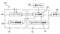
図1を参照すると、薬液注入装置100と、薬液充填装置200と、撮像装置であるCT装置300と、を有している、本発明の第1の実施形態による透視画像撮像システム1000が示されている。(First embodiment)
Referring to FIG. 1, there is shown a fluoroscopic
薬液充填装置200は、薬液容器600に収容された薬液を薬液シリンジ500内に充填する。薬液注入装置100は、薬液シリンジ500内に充填された薬液を薬液シリンジ500から被験者へ注入する。これら薬液充填装置200と薬液注入装置100とで薬液充填注入システムが構成される。CT装置300は、薬液が注入された被験者の透視画像を撮像するものであり、撮像を実行する撮像ユニット301と、撮像ユニット301の動作を制御する撮像制御ユニット302と、を有している。撮像制御ユニット302と薬液注入ユニット100とは相互に通信可能に接続されている。 The chemical
また、薬液注入装置100およびCT装置300は、病院管理サーバ400と通信可能に接続されている。病院管理サーバ400は、カルテ情報を管理するものであり、被験者の情報を含むカルテ情報のデータベースを有している。 Moreover, the
薬液シリンジ500は、シリンダ501と、シリンダ501内に進退自在に設けられたピストン502と、を有する。シリンダ501はその一端部に導管部501bを有しており、ピストン502は、シリンダ501の一端部と反対側の端部である他端部からシリンダ501内に挿入されている。シリンダ501の他端部にはシリンダフランジ501aが形成されている。同様にピストン502にも、そのシリンダ501に挿入されている側の端部と反対側の端部にピストンフランジ502aが形成されている。 The
シリンダ501にはICタグ503が設けられている。ICタグ503は、無線ICタグ、非接触ICタグ、非接触ICチップ、非接触データキャリアなどとも呼ばれ、RF−ID(Radio Frequency-Identification)技術を利用するデバイスである。本発明においては、ICタグ503は、無線等の非接触の通信媒体を用いてデータ通信を行い、固体識別符号などの情報を追記または書き換え可能に記録するメモリ付き集積回路を有する媒体を示す。 The
ICタグ503には、この薬液シリンジ500に関するデータ(シリンジデータ)、例えば、メーカ、品番、シリアル番号といった固有識別番号、製造年月日、耐用期限(回数)、容量、およびピストンストローク等のデータが記録されている。ICタグ503は、シリンダ501の外周面に、ラベルによって貼り付けられていてもよいし、接着剤によって接着されていてもよい。あるいは、ICタグ503をシリンダ501に埋め込むこともできる。 The
以下に、薬液充填装置200および薬液注入装置100について詳しく説明する。 Hereinafter, the chemical
まず、薬液充填装置200について、図1および図1に示す薬液充填装置200のブロック図である図2を参照して説明する。 First, the chemical
薬液充填装置200は、薬液シリンジ500が着脱自在に装着され、装着された薬液シリンジ500内に薬液を充填する。薬液充填装置200が薬液シリンジ500に充填する薬液の量は、ここで薬液が充填された薬液を薬液注入装置100(図1参照)によって被験者に注入する薬液の量と等しい。したがって、薬液シリンジ500への薬液の充填量は、この透視画像撮像システム1000による被験者の検査条件に応じて異なる。 In the chemical
このように、薬液を必要な量だけ薬液シリンジ500に充填するため、薬液充填装置200は、この薬液充填装置200の動作全体を制御する充填制御ユニット210と、充填制御ユニット210からの指令に基づいて薬液シリンジ500を操作する充填動作機構220と、外部装置との間でデータの送受信を行うためのインターフェイス部の一つであるリーダ/ライタ230と、入力部240と、表示部250と、を有する。 Thus, in order to fill the
リーダ/ライタ230は、ICタグ503に書き込まれているデータの読み出し、およびICタグ503へのデータの書き込みを非接触で行う。したがって、リーダ/ライタ230は、薬液充填装置200に薬液シリンジ500が装着された状態において、薬液シリンジ500に設けられたICタグ503が通信可能範囲内にあるような位置に配置される。 The reader /
入力部240は、キースイッチやタッチパネルなどで構成することができ、操作者によるデータの入力操作を受け付ける。入力部240には、薬液シリンジ500への薬液の充填量を決定するのに用いる、検査条件に関するデータが入力される。 The
検査条件に関するデータは、主として被験者データ、薬液データおよび撮像条件に分けられる。被験者データとしては、例えば、この薬液シリンジ500に充填された薬液が注入される被験者の体重、性別、身長、年齢などが挙げられる。薬液データとしては、例えば、充填する薬液の種類、メーカ、品番、粘度、薬液が造影剤である場合はそのヨード含有濃度、さらには、他の種類の薬剤である生理食塩水を併用するか否か、などが挙げられる。撮像条件としては、被験者の撮像部位、撮像時間などが挙げられる。 Data relating to examination conditions is mainly divided into subject data, drug solution data, and imaging conditions. The subject data includes, for example, the weight, sex, height, age, and the like of the subject into which the chemical solution filled in the
入力部240からは、これらのうち少なくとも充填量を算出するのに必要なデータが入力される。なお、シリンジデータも操作者によって入力部240から入力するように薬液充填装置200が構成されてもよい。この場合、薬液充填装置200はICタグ503からのデータを読み出す必要はないので、データ送受信部は書き込みの機能を有するライタであってもよい。 From the
充填制御ユニット210は、判定部211と、演算部212と、充填制御部213と、データベース214と、を有する。 The filling
判定部211は、リーダ/ライタ230で読み出されたシリンジデータと、入力部240から入力された検査条件に関するデータとから、薬液シリンジ500への薬液の充填の適否を判断する。薬液の充填の適否とは、例えば、薬液シリンジ500が耐用期限(回数)を超過していないかどうか、充填する薬剤がこの検査に適した薬剤であるかどうか、および薬液シリンジ500と薬剤との組み合わせが適切であるかどうかなどである。判定の結果、不適と判断されれば、充填制御ユニット210は、ブザー(不図示)や警告ランプ(不図示)等によって警報を発し、以降の動作を停止する。一方、適切であると判断されれば、判定部211は、リーダ/ライタ230で読み出されたシリンジデータおよび入力部240から入力されたデータをそのまま演算部212へ送る。 The
演算部212は、送られてきたデータに基づいて、薬液シリンジ500への薬液の充填量を算出する。薬液の充填量、すなわち被験者への薬液の注入量は、良好な画像を撮像するのに最適な値が、被験者の体重、身長、性別、年齢などの被験者因子、薬液の成分、物性などの薬液因子、および撮像部位、撮像時間などの撮像因子によって異なる。 The
例えば、薬液が造影剤である場合、良好な画像を得るために重要な因子の1つが、ヨードの注入総量である。造影剤は、その種類によってヨード含有濃度が異なっており、違う種類の造影剤では、同じ量であってもそれに含まれるヨード量は異なる。 For example, when the drug solution is a contrast medium, one important factor for obtaining a good image is the total amount of iodine injected. Contrast agents have different iodine concentrations depending on the type, and different types of contrast agents have different amounts of iodine contained in the same amount.
そこで、撮像部位ごとの係数データ、薬剤の種類ごとの有効成分データ(例えば造影剤においては、造影剤の種類ごとのヨード含有濃度データ)、および被験者の体重、身長といった身体情報に対応した薬剤の注入総量データなどが、データベース214に格納されている。 Therefore, coefficient data for each imaging region, effective component data for each type of drug (for example, in the case of contrast medium, iodine-containing concentration data for each type of contrast medium), and drug information corresponding to physical information such as the body weight and height of the subject. Total injection amount data and the like are stored in the
演算部212は、データベース214を参照しつつ、前述した検査条件に関するデータを、こういった各種因子を考慮して予め決められた計算式に当てはめることによって、薬液の充填量を算出する。なお、演算部212での薬液の充填量の算出手順は、従来の薬液注入装置における薬液の注入量の算出手順と同じでよいので、ここでは、具体的な計算式および計算手法などの説明は省略する。 The
さらに演算部212は、入力部240から入力されたデータおよび演算部212で算出された充填量を、リーダ/ライタ230を通じてICタグ503に追記する。既にこれらのデータが前回の充填時に記録されている場合は、これらのデータを書き換える。 Further, the
充填制御部213は、演算部212で算出された充填量に基づいて、算出された充填量だけ薬液シリンジ500に薬液が充填されるように充填動作機構220を制御する。 The filling
充填動作機構220は、図1に示すように、シリンダホルダ221と、ピストンホルダ222とを有する。 As shown in FIG. 1, the filling
シリンダホルダ221には、薬液シリンジ500のシリンダフランジ501aを受け入れる円弧状の凹部がその側面に形成されている。凹部は、シリンダフランジ501aが載置される載置面を有する段差状に形成されている。この載置面の上に、導管部501bが上向きとなるようにシリンダフランジ501aを載せることによって、シリンダ501がシリンダホルダ221に保持される。 The
ピストンホルダ222は、シリンダホルダ221の下方においてシリンダホルダ221と対向して配置され、シリンダホルダ221から離れる方向(矢印A方向)およびシリンダホルダ221に接近する方向(矢印B方向)に移動可能に設けられている。ピストンホルダ222も、シリンダホルダ221と同様に、ピストン502を受け入れる凹部が側面に形成されている。ピストン502は、そのピストンフランジ502aをピストンホルダ222の下側(シリンダホルダ221と向き合う側と反対側)に位置させた状態で凹部に保持される。 The
上述のようにシリンダフランジ501aおよびピストン502を保持した状態で、ピストンホルダ222を矢印A方向に移動させることで、シリンダ501からピストン502が引き出される。一方、ピストンホルダ222を矢印B方向に移動させることで、ピストン502がシリンダ501内に押し込まれる。 The
ピストンホルダ502の移動には、ピストンホルダ502を直線運動させることができる機構であれば、例えばボールねじ機構など任意の駆動機構を用いることができる。ピストンホルダ502の駆動機構としてボールねじ機構を用いる場合、ボールねじ軸をピストンホルダ502の移動方向と平行に配するとともに、ボールねじ軸に螺合するボールねじナットにピストンホルダ502を固定する。これにより、ボールねじ軸の回転に従って、ピストンホルダ502をボールねじ軸の軸方向に移動させることができる。ボールねじ軸の駆動源には、例えばステッピングモータを用いることができる。 For the movement of the
薬液シリンジ500への薬液の充填量は、シリンダ221からピストン222を引き出す方向へ移動させたときの、シリンダ221に対するピストン222の移動量に比例する。したがって、充填制御部213は、演算部212で算出された充填量に対応した移動量だけピストンホルダ222が移動するように充填動作機構を制御する。これによって、薬液シリンジ500には、演算部212で算出された量の薬液が充填される。 The filling amount of the chemical liquid into the
表示部250には、入力部240で入力された各種データや、演算部212で算出された充填量、充填動作の進捗状況などを、数値や画像などで表示することができる。本実施形態では、図1に示すように、薬液充填装置200はタッチパネル241を有しており、これが図2に示す入力部240および表示部250を兼ねている。 The
上述した薬液充填装置200では、薬液シリンジ500をその導管部501bが上向きとなるように鉛直方向に立てた状態で保持した例を示したが、保持された薬液シリンジ500の向きは、水平方向や斜め方向など任意であってよい。また、薬液シリンジ500の操作についても、シリンダホルダ221を固定しておきピストンホルダ222を移動させる例を示したが、ピストンホルダ222を固定してシリンダホルダ221を移動させるようにしてもよい。あるいは、シリンダホルダ221およびピストンホルダ222の双方を移動させるようにすることもできる。 In the chemical
さらに、充填制御ユニット210は判定部211を有しているが、判定部211は本発明においては必須ではない。例えば、薬液シリンジ500および薬液の適否については操作者自身が判断してもよいし、判定部211の機能を演算部212に組み込み、演算部212での処理過程で適否を判断するようにしてもよい。Furthermore, although the filling
次に、薬液注入装置100について、図3および図4を参照して説明する。 Next, the
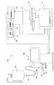
薬液注入装置100は、例えば図3に示すように、スタンド111に連結された可動アーム112の上部に取り付けられた注入ヘッド110と、注入ヘッド110とケーブル102によって接続されている注入制御ユニット101とを有する。注入制御ユニット101は、入力部である操作パネル103と、表示部104と、ケーブル108で接続されたハンドユニット107とを有し、注入ヘッド110の動作を制御する。 For example, as shown in FIG. 3, the
注入ヘッド110は、図4に示すように、一度に2本の薬液シリンジ500を装着できるように、ヘッド本体113に、それぞれシリンダ501を保持する2つの凹部114が形成されている。ヘッド本体113には、互いに独立して駆動される2つのピストン駆動機構130が、各凹部114に対応して設けられている。ピストン駆動機構130は、その先端部でピストン502のピストンフランジを保持できるように構成されている。 As shown in FIG. 4, the
2本の薬液シリンジ500が装着される場合、薬液シリンジ500に充填されている薬液としては、例えば、一方を造影剤、他方を生理食塩水とすることができる。ヘッド本体113に装着された2本の薬液シリンジ500は、連結チューブ530により接続される。連結チューブ530には、先端部にカテーテル(不図示)が接続された延長チューブ(不図示)が連結される。カテーテルを被験者に刺入した状態でピストン駆動機構130によりピストン502をシリンダ501に押し込むことで、造影剤の注入、生理食塩水の注入、および両者の同時注入が可能となる。 When two
さらに、ヘッド本体113には、薬液シリンジ500に設けられたICタグ503に書き込まれているデータの読み出しおよびICタグ503へのデータの書き込みを非接触で行うリーダ/ライタ140が、各薬液シリン500の装着位置に対応して設けられている。リーダ/ライタ140は、外部装置、具体的には薬液充填装置200との間でデータの送受信を行うためのインターフェイス部の一つである。 Further, in the head
上述した薬液注入装置100についてさらに、各部の機能に着目して図5を参照して説明する。なお,図5では、薬液注入装置100をCT装置300および病院管理サーバ400(いずれも図1参照)と通信可能に接続するためのインターフェイスは省略している。 The above-described
注入制御ユニット101は、注入制御部121および注入プロファイル格納部122を有している。薬液シリンジ500が注入ヘッド110に装着され、リーダ/ライタ140がICタグ503(図4参照)から各データを読み出すと、読み出された各データは、注入制御部121へ送られる。 The
この段階で注入制御部121は、リーダ/ライタ140が読み出した各データを表示部104に数値や画像などで表示させるとともに、注入プロファイル格納部122から注入プロファイルを読み出す。リーダ/ライタ140から送られるデータには、薬液充填装置200(図1参照)でICタグ503に書き込まれた充填量のデータも含まれている。薬液注入装置100では、この充填量のデータを注入量のデータとして扱う。 At this stage, the
注入プロファイル格納部122には、薬液に応じた少なくとも1つの注入プロファイルが格納されている。注入プロファイルの例としては、
(1)注入速度が一定のプロファイル、
(2)注入速度が異なる複数の段階を有するプロファイル、
(3)少なくとも1つの段階(1つのみの場合を含む)として造影剤と生理食塩水の同時注入段階を有するプロファイル、
(4)少なくとも1つの段階(1つのみの場合を含む)として注入開始からの経過時間に対して注入速度が変化する段階を有するプロファイル、および
(5)少なくとも1つの段階(1つの段階のみの場合を含む)として注入開始からの経過時間に対して注入圧力が変化する段階を含むプロファイル、
などが挙げられる。いずれの場合でも、薬液の注入が所定の時間で完了するように、注入速度の変化率が決定される。The injection
(1) Profile with constant injection rate,
(2) a profile having a plurality of stages with different injection rates;
(3) a profile having a simultaneous injection phase of contrast agent and saline as at least one stage (including only one case);
(4) a profile having a stage where the infusion rate varies with time since the start of infusion as at least one stage (including only one), and (5) at least one stage (only one stage) A profile including a stage in which the injection pressure changes with respect to the elapsed time from the start of injection,
Etc. In any case, the rate of change of the injection rate is determined so that the injection of the chemical solution is completed in a predetermined time.
少なくとも1つの段階(1つのみの場合を含む)として注入開始からの経過時間に対して注入速度が変化する段階を有するプロファイルの好ましい例としては、造影剤の注入速度を注入開始からある時間までは線形に低下させ、それ以降は注入速度を一定に維持または上昇させるプロファイル、少なくとも1つの段階で造影剤の注入速度を低下させ(例えば線形に)、その間同時に、生理食塩水の注入速度を上昇させるプロファイルが挙げられる。 As a preferable example of a profile having a step in which the injection rate changes with respect to the elapsed time from the start of injection as at least one step (including only one case), the contrast agent injection rate is changed from the start of injection to a certain time. Decreases linearly and thereafter keeps the injection rate constant or increases, decreasing the contrast agent injection rate in at least one stage (eg linearly), while increasing the saline injection rate simultaneously Profile to be used.
さらに注入制御部121は、薬液シリンジ500から得られた薬液の注入量のデータと、注入プロファイル格納部122から読み出した注入プロファイルとに基づいて、所定の量の薬液が所定の時間で、かつ所定の注入プロファイルで被験者に注入されるように薬液の注入条件を決定する。そして注入制御部121は、決定した注入条件従った動作シーケンスでピストン駆動機構130が動作するように、ピストン駆動機構130を制御する。 Furthermore, the
操作パネル123は、注入開始ボタンを有している。操作者がこの注入開始ボタンを操作することによって、注入制御部121はピストン駆動機構130を実際に動作させる。なお、薬液ごとに複数の注入プロファイルが注入プロファイル格納部122に格納されている場合、操作パネル103はプロファイル選択ボタンをさらに有し、操作者がそれらの注入プロファイルから1つを選択できるようになっている。 The operation panel 123 has an injection start button. When the operator operates the injection start button, the
次に、上述した透視画像撮像システム1000による透視画像の撮像手順を説明する。 Next, a procedure for capturing a fluoroscopic image by the above-described fluoroscopic
まず、操作者は、空の薬液シリンジ500、すなわち薬液が充填されていない薬液シリンジ500、およびこの薬液シリンジ500に充填する薬液が収容されている薬液容器600を用意する。薬液シリンジ500は、ピストン502がシリンダ501に最も押し込まれた状態にある。なお、透視画像システム1000を構成する薬液注入装置100、薬液充填装置200、およびCT装置300等は既に用意されているものとする。 First, the operator prepares an empty chemical
次いで、操作者は、用意した空の薬液シリンジ500を、導管部501bを上に向けて薬液充填装置200に装着する。薬液シリンジ500の装着後、操作者は、薬液容器600と薬液シリンジ500とをチューブ610によって接続する。 Next, the operator attaches the prepared empty chemical
次いで、操作者は、前述したような、薬液シリンジ500への薬液の充填量を決定するのに必要なデータを薬液充填装置200のタッチパネル241から入力する。その一方で、薬液充填装置200は、装着された薬液シリンジ500のICタグ503に記録されているシリンジデータを読み出す。 Next, the operator inputs data necessary for determining the filling amount of the chemical solution into the
薬液充填装置200は、操作者により入力されたデータおよびICタグ503から読み出したシリンジデータから、薬液シリンジ500への薬液の充填の適否を判定する。その結果、適正と判定されれば、薬液充填装置200は、入力されたデータを用いて薬液シリンジ500への薬液の充填量を算出し、算出結果に従って、薬液シリンジ500に薬液を充填する。 The chemical
以下に、薬液シリンジ500に薬液が充填されるまでの操作者による薬液充填装置200の操作手順の一例を、薬液が造影剤である場合で説明する。 Hereinafter, an example of the operation procedure of the chemical
薬液シリンジ500が薬液充填装置200に装着され、リーダ/ライタ230によってICタグ504のデータが読み出されると、タッチパネル241には初期画面として薬液シリンジ500の種類(例えば、容量や用途)が表示される。併せて、タッチパネル241には、この薬液を注入しようとする身体区分の模式画像も表示される。この身体区分の模式画像は、人体を例えば「頭部」、「胸部」、「腹部」、「脚部」というように複数の区分に分割して模式的に表した画像である。操作者は、これら模式画像のうち1つに接触することで1つの身体区分を選択する。身体区分が選択されると、選択された身体区分は暗転または色相の変化等によって、他の身体区分と視覚的に区別される。 When the
操作者が身体区分を選択すると、タッチパネル241には選択された身体区分に応じた撮像部位がさらに表示される。撮像部位とは、例えば、身体区分として「胸部」を選択した場合は、「心臓部」および「肺部」である。撮像部位は、文字で表示されるようにしてもよいし、撮像部位の特徴を図案化したアイコンと併せて表示されるようにしてもよい。操作者は、これらの撮像部位のうち1つに接触することで1つの撮像部位を選択する。撮像部位が選択されると、選択された撮像部位のみが画面上に残る。 When the operator selects a body segment, an imaging region corresponding to the selected body segment is further displayed on the touch panel 241. For example, when “chest” is selected as the body segment, the imaging region is “heart” and “lung”. The imaging part may be displayed in characters, or may be displayed together with an icon in which the characteristics of the imaging part are designed. The operator selects one imaging part by touching one of these imaging parts. When an imaging part is selected, only the selected imaging part remains on the screen.
次に、タッチパネル241には、被験者の体重の入力画像が表示される。体重の入力画像では、例えば、デフォルトとして標準体重をタッチパネル241に表示させ、それを操作者が「+」ボタンおよび「−」ボタンで増減させ、最終的に「確定」ボタンに接触することによって、体重を入力することができる。あるいは、体重表示欄とともにテンキーをタッチパネル241に表示させ、操作者がテンキーに接触することによって体重を入力させることもできる。 Next, an input image of the subject's weight is displayed on the touch panel 241. In the input image of the weight, for example, the standard weight is displayed on the touch panel 241 as a default, and the operator increases or decreases it with the “+” button and the “−” button, and finally touches the “confirm” button. You can enter your weight. Alternatively, the numeric keypad can be displayed on the touch panel 241 along with the weight display field, and the operator can input the weight by touching the numeric keypad.
次に、タッチパネル241には、薬液に関する情報を設定する画面が表示される。例えば薬剤が造影剤である場合、造影剤のヨード含有濃度は造影剤のメーカおよび品番によって決まっているので、この薬液充填装置で充填する可能性のある造影剤のヨード含有濃度の一覧がボタンとしてタッチパネル241に表示される。操作者が、これから充填しようとする造影剤のヨード含有濃度に対応するボタンに接触することによって、ヨード含有濃度が入力されることになる。または、メーカ名および品番の一覧が表示され、一覧の中から操作者がメーカ名および品番を選択するようにしてもよい。その場合は、薬液充填装置は、造影剤のメーカ名および品番に対応づけられたヨード含有濃度に関するデータベースを有している。 Next, the touch panel 241 displays a screen for setting information related to the chemical solution. For example, if the drug is a contrast agent, the iodine concentration of the contrast agent is determined by the manufacturer and product number of the contrast agent, so a list of iodine concentrations of contrast agents that can be filled with this chemical solution filling device is displayed as a button. Displayed on the touch panel 241. When the operator touches the button corresponding to the iodine concentration of the contrast medium to be filled, the iodine concentration is input. Alternatively, a list of manufacturer names and product numbers may be displayed, and the operator may select the manufacturer name and product number from the list. In that case, the chemical solution filling apparatus has a database relating to the iodine-containing concentration associated with the manufacturer name and product number of the contrast agent.
ここまでの段階で、入力された各項目はタッチパネル241の画面上に表示されたままになっており、操作者は、これまでに入力した項目を画面上で確認することができる。タッチパネル241には確認ボタンが表示され、操作者がこの確認ボタンに接触することによって、薬液充填装置200は、前述したように薬液の充填の適否を判定し、適正と判定されれば、薬液の充填量を算出する。 At this stage, the input items are still displayed on the screen of the touch panel 241, and the operator can check the items input so far on the screen. When a confirmation button is displayed on the touch panel 241 and the operator touches the confirmation button, the chemical
充填量の算出後、算出された充填量およびスタートボタンがタッチパネル241にさらに表示される。操作者は、表示された充填量を確認し、スタートボタンに接触する。充填動作機構220が動作し、薬液シリンジ500に薬液が充填される。 After the filling amount is calculated, the calculated filling amount and a start button are further displayed on the touch panel 241. The operator confirms the displayed filling amount and touches the start button. The filling
薬液の充填中は、薬液の充填中であることを操作者が視覚的に認識できるように、薬液の充填状況をタッチパネル241に表示することが好ましい。その際の表示画像としては、例えば、薬液シリンジ500内に薬液が充填されていく様子をアニメーション表示した画像、充填動作機構220の動作に対応して薬液の充填量を示す数値が刻々と増加していくような画像、またはこれらを組み合わせた画像等が挙げられる。 During the filling of the chemical solution, it is preferable to display the filling state of the chemical solution on the touch panel 241 so that the operator can visually recognize that the chemical solution is being filled. As the display image at that time, for example, an image showing an animation of the state in which the
薬液が生理食塩水である場合は、上述したような詳細な設定は不要であり、充填量をマニュアルで設定することもできる。そのためには、タッチパネル241の初期画面には、前述した薬液シリンジ500の種類の他に、マニュアル操作ボタンが表示されるようにしておく。操作者がマニュアル操作ボタンに接触すると、マニュアル操作モードに移行する。マニュアル操作モードでは、例えば、設定する充填量を表す数値を、「+」ボタンおよび「−」ボタンとともに表示させ、操作者がこれらのボタンに適宜接触することによって数値を増減させて充填量を設定するようにすることができる。または、「+」ボタンおよび「−」ボタンの代わりにテンキーボタンを表示させ、テンキーボタンから数値を直接入力することによって充填量を設定することもできる。充填量を設定したら、操作者はタッチパネル241上に表示されているスタートボタンに接触し、これによって充填動作が開始する。 When the drug solution is physiological saline, detailed setting as described above is unnecessary, and the filling amount can be set manually. For this purpose, a manual operation button is displayed on the initial screen of the touch panel 241 in addition to the type of the
なお、薬液の充填中に、薬液シリンジ500内へのエアの混入を検出するために、薬液容器600と薬液シリンジ500とを接続するチューブ610にエア検出センサ(不図示)を設けることが好ましい。エア検出センサには、チューブ610内にエアが存在しているか否かを検出することができるものであれば、光学式、超音波式、および静電容量式など任意の方式のセンサを用いることができる。いずれの方式も、チューブ610内にエアが存在しているときと存在していないときとでの特性変化、例えば光学式であれば屈折率、反射率、透過率などといった光学特性の変化、超音波式であれば共振特性の変化、静電容量式であれば静電容量の変化を検出することによって、チューブ610内のエアの有無を検出する。 In order to detect mixing of air into the chemical
薬液の充填後、タッチパネル241には、薬液の充填が完了した旨のメッセージおよび確認ボタンが表示される。操作者が薬液の充填完了を確認し、確認ボタンに接触すると、薬液充填装置200は、入力されたデータおよび算出された充填量のデータを薬液シリンジ500のICタグ503に書き込む。 After filling the chemical solution, the touch panel 241 displays a message indicating that the filling of the chemical solution is completed and a confirmation button. When the operator confirms completion of filling of the chemical liquid and touches the confirmation button, the chemical
データの書き込みが終了したら、操作者は、薬液が充填された薬液シリンジ500を薬液充填装置200から取り外し、薬液注入装置100の注入ヘッド110に装着する。また、操作者は、薬液シリンジ500に連結チューブ530を介して(1本の薬液シリンジ500のみが装着されている場合は直接)延長チューブを接続し、延長チューブの先端に設けられているカテーテルを被験者に刺入する。 When the writing of data is completed, the operator removes the
次いで、操作者は、必要に応じて注入プロファイルを選択する。一方、注入ヘッド110は、装着された薬液シリンジ500のICタグ503に記録されているデータを読み出す。薬液注入装置100は、ICタグ503から読み出されたデータに基づいて、予め決められた所定の注入プロファイルまたは操作者が選択した注入プロファイルによる薬液の注入が行われるように、薬液の注入条件を決定する。 The operator then selects an infusion profile as needed. On the other hand, the
薬液の注入条件が決定されたら、操作者は、入力部123の注入開始ボタンを操作する。これによって、ピストン駆動機構130は決定された注入条件に従った動作シーケンスで駆動され、薬液シリンジ500内の薬液が被験者に注入される。 When the injection condition of the chemical is determined, the operator operates the injection start button of the input unit 123. Thereby, the
薬液の注入後、注入制御部121は、リーダ/ライタ140を通じて、薬液の注入が完了したことを示すデータをICタグ503に書き込む。これは薬液シリンジ500の使用履歴を管理するためである。だたし、薬液シリンジ500の使用履歴は、薬液充填装置200によってICタグ503に書き込まれたデータを参照することによっても代用できるので、薬液注入装置100によるICタグ503へのデータの書き込みは省略することもできる。また、薬液シリンジ500の使用履歴は、薬液充填装置200にデータベースを構成し、薬液充填装置200で管理することもできる。 After injection of the chemical solution, the
被験者への薬液の注入後、薬液注入装置100の注入制御ユニット101からCT装置300の撮像制御ユニット302へ信号が送られ、撮像制御ユニット302からの制御信号に基づいて撮像ユニット301は被験者の透視画像を撮像する。CT装置300にて撮像された画像は、直接または薬液注入装置100を介して病院管理サーバ400へ送られる。病院管理サーバ400は、そのデータベースにCT検査結果を記録する。一方、薬液注入装置100の注入制御ユニット101は、リーダ/ライタ140から読み出した各種データ、薬液の注入時間、注入速度、注入圧力などから選ばれる薬液注入データを病院管理サーバ400に送信する。したがって、病院管理サーバ400のデータベースには、CT検査結果とともに、薬液の注入条件も記録される。 After injecting the chemical liquid into the subject, a signal is sent from the
また、CT装置300から薬液注入装置100に、CT撮像条件データ(放射線量、放射線照射タイミング等の曝射条件等)が送信され、薬液注入装置100は、病院管理サーバ400に送信するデータとして、上記の撮像条件データを付加するようにしてもよい。CT撮像条件データは、CT装置300から直接、病院管理サーバ400に送信してもよい。 Further, CT imaging condition data (such as radiation conditions, exposure conditions such as radiation irradiation timing) is transmitted from the
以上説明したように、薬液充填装置200は、検査条件に関するデータを用いて薬液シリンジ500への薬液の充填量を算出し、薬液シリンジ500には薬液が必要な量だけ充填されるので、薬液の無駄をなくすることができる。 As described above, the
また、薬液シリンジ500に充填された薬液の量は薬液シリンジ500に設けられたICタグ503に書き込まれ、薬液注入装置100は、ICタグ503に書き込まれたデータを読み出すように構成されている。そのため、薬液注入装置100では薬液の注入量を算出する必要はなく、したがって、注入量を算出するのに必要なデータを操作者が薬液注入装置100に入力する必要もない。このように、薬液シリンジ500に薬液を充填するのに用いたデータを薬液注入装置100による薬液の注入にも利用することで、操作者の作業負担を大幅に軽減することができる。 Further, the amount of the chemical solution filled in the
さらに、薬液シリンジ500への薬液の充填量のデータ(言い換えると被験者への薬液の注入量のデータ)は、薬液シリンジ500に設けられたICタグ503に書き込まれている。したがって、薬液注入装置100は、確実に、薬液注入装置100に実際に装着されている薬液シリンジ500についてのデータに基づいて薬液の注入条件を決定し、その注入条件で薬液を注入することができる。その結果、被験者に対して誤った注入条件で薬液が注入されるのを防止することができる。 Furthermore, data on the filling amount of the chemical solution into the chemical solution syringe 500 (in other words, data on the injection amount of the chemical solution to the subject) is written in the
本形態では、薬液充填装置200で薬液シリンジ500に充填する薬液の量を算出するのに必要なデータは全て、ICタグ503に書き込まれたデータと入力部240から入力されるデータとから与えられる例を示した。しかし、これらのデータの一部を、病院管理サーバ400のデータベースに記録しておき、必要に応じて病院管理サーバ400に記録されているこれらのデータを読み出すことができるように、薬液充填装置200と病院管理サーバ400とを相互に通信可能に接続してもよい(図1に一点鎖線で示す)。 In this embodiment, all the data necessary for calculating the amount of the chemical liquid to be filled in the chemical
このように、一部のデータをデータベースとして予め用意しておくことで、ICタグ503に書き込まれるデータ量、および操作者によるデータの入力作業を削減することができる。 Thus, by preparing a part of data as a database in advance, the amount of data written to the
データベースとして用意しておくことのできるデータは、あるデータが分かっていた場合に、そのデータから特定できるデータである。シリンジデータの場合、薬液シリンジ500の固有識別番号(例えば品番とシリアル番号)が分かれば、他のデータは固有識別番号から特定することができる。薬液データの場合も同様に、薬液の固有識別番号(例えば、品番とロット番号)が分かれば、他のデータは固有識別番号から特定することができる。 Data that can be prepared as a database is data that can be identified from the data when the data is known. In the case of syringe data, if the unique identification number (for example, the product number and serial number) of the
こういった固有識別番号から特定することのできるデータを記録しておくデータベースは、病院管理サーバ400ではなく、薬液充填装置200または薬液注入装置100が有していてもよい。ただし、病院管理サーバ400には、被験者に関するデータはもちろん、薬液注入装置100、薬液充填装置200、およびCT装置300などの各設備に関するデータも記録されているので、データの一元管理が可能となる。さらには、薬液シリンジ500の使用履歴についても病院管理サーバ400で管理することもできる。 A database in which data that can be specified from such a unique identification number is recorded may be included in the drug
薬液充填装置200と病院管理サーバ400とを通信可能に接続する場合、薬液充填装置200は、例えば図6に示すように、データ送受信部として、リーダ/ライタ230の他にインターフェイス260をさらに有する構成とすることができる。病院管理サーバ400(図1参照)は、インターフェイス260を介してデータを送受信可能に接続されている。 When the chemical
病院管理サーバ400と薬液充填装置200との接続方式は有線接続であってもよいし、無線接続であってもよい。有線接続の場合、インターフェイス260としては例えばケーブルコネクタを用いることができる。無線接続の場合は、インターフェイス260として例えば無線データ通信機を用いることができる。 The connection method between the
なお、図6に示す例では、演算部212が判定部の機能も有する場合を示している。従って、リーダ/ライタ230で読み出されたデータおよび入力部240から入力されたデータは演算部212に送られ、ここで薬液の充填の適否を判定し、充填量を算出する。演算部212へ送られるデータは、シリンジの固有識別番号および薬液の固有識別番号の少なくとも一方を含んでいる。演算部212は、送られてきた固有識別番号に対応するデータを、インターフェイス260を介して病院管理サーバ400から呼び出し、充填量の算出に利用する。充填制御ユニット210でのそれ以外の処理については図2の場合と同様なので、ここではその説明は省略する。 In the example illustrated in FIG. 6, the
また、本形態では、薬液充填装置200による薬液の充填量を、演算部212での算出によって求めた例を示したが、データベース214が、充填制御ユニット210に入力された各検査条件に対応する種々の充填量データを有している場合は、演算部212は計算ではなくデータベース214を参照するだけで薬液の充填量を求めることができる。 Further, in the present embodiment, the example in which the chemical liquid filling amount by the chemical
(第2の実施形態)
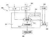
図7は、本発明の第2の実施形態による透視画像撮像システムの全体の構成を示す図である。図8は図7に示す薬液充填装置のブロック図であり、図9は図7に示す薬液注入装置のブロック図である。なお、図7〜図9では、第1の実施形態と同じ構成については第1の実施形態で用いた符号と同じ符号を付し、その詳しい説明は省略する。また、図9では、薬液注入装置100を病院管理サーバ400と通信可能に接続するためのインターフェイスは省略している。(Second Embodiment)
FIG. 7 is a diagram showing an overall configuration of a fluoroscopic imaging system according to the second embodiment of the present invention. 8 is a block diagram of the chemical liquid filling apparatus shown in FIG. 7, and FIG. 9 is a block diagram of the chemical liquid injection apparatus shown in FIG. 7 to 9, the same components as those in the first embodiment are denoted by the same reference numerals as those used in the first embodiment, and detailed description thereof is omitted. Further, in FIG. 9, an interface for connecting the
第1の実施形態では、薬液シリンジ500の固有識別番号を記録しているデータキャリアが追記または書き換え可能である場合を説明した。本実施形態では、データキャリアとしてバーコード504が薬液シリンジ500に設けられている。バーコード504にはシリンジデータが記録されており、記録されているデータの変更はできない。 In 1st Embodiment, the case where the data carrier which has recorded the unique identification number of the chemical |
薬液シリンジ500にバーコード504が設けられていることに伴い、薬液充填装置200は、バーコード504に記録されているデータを読み出すためのリーダ270を有している。同様に薬液注入装置100も、バーコード504に記録されているデータを読み出すためのリーダ150を有している。 Along with the provision of the
さらに、薬液充填装置200と薬液注入装置100とはデータ通信可能に接続されている。そのため、薬液充填装置200および薬液注入装置100はそれぞれ、データ送受信部としてインターフェイス280、160を有しており、これらインターフェイス280、160を介して、薬液充填装置200と薬液注入装置100との間でデータの送受信が行われる。薬液充填装置200と薬液注入装置100との接続方式は有線接続であってもよいし、無線接続であってもよい。有線接続の場合、インターフェイス280、160としては例えばケーブルコネクタを用いることができる。無線接続の場合は、インターフェイス280、160として例えば無線データ通信機を用いることができる。 Furthermore, the chemical
薬液充填装置200および薬液注入装置100について、主として第1の実施形態との相違点を中心に説明する。以下の説明では、第1の実施形態と同様の事項については省略する。 The chemical
薬液充填装置200では、リーダ270で読み出したシリンジデータは、演算部212に送られる。演算部212は、リーダ270から送られたシリンジデータおよび入力部240から入力されたデータに基づいて、薬液の充填の適否を判定し、充填量を算出する。充填量が算出されたら、演算部212は、リーダ270で読み出したシリンジデータ、入力部240から入力されたデータ、および算出した充填量のデータを、インターフェイス280を介して薬液注入装置100へ送信する。 In the chemical
薬液注入装置100では、薬液充填装置200から送信されたデータが、インターフェイス160を介して受信され、注入制御部121へ送られる。 In the chemical
一方、薬液充填装置200によって薬液が充填された薬液シリンジ500は、薬液充填装置200から取り外され、薬液注入装置100に装着される。薬液シリンジ500が薬液注入装置100に装着されると、リーダ150は、薬液シリンジ500に設けられたバーコード504からシリンジデータを読み出す。リーダ150で読み出されたシリンジデータは、注入制御部121へ送られる。 On the other hand, the
注入制御部121は、リーダ150から送られたシリンジデータと、インターフェイス160を介して薬液充填装置200から送信されたシリンジデータとを比較する。比較の結果、両者のシリンジデータが異なっていれば、薬液注入装置100に装着された薬液シリンジ500が異なる旨を警報として発する。両者のシリンジデータが一致していれば、第1の実施形態と同様に薬液の注入条件を決定し、決定した注入条件に従った動作シーケンスでピストン駆動機構130が動作するようにピストン駆動機構130を制御する。 The
以上のように、追記または書き換えができないデータキャリアを用いた場合であっても、薬液充填装置200と薬液注入装置100とを相互にデータ通信可能に接続することで、薬液シリンジ500に薬液を充填するのに用いたデータを薬液注入装置100による薬液の注入に利用することができる。その結果、操作者の作業負担が大幅に軽減される。 As described above, even when a data carrier that cannot be additionally written or rewritten is used, the
また、薬液注入装置100は、実際に装着されている薬液シリンジ500のシリンジデータを読み出すので、実際に装着されている薬液シリンジ500に対応した注入条件で薬液を注入することができる。その結果、被験者に対して誤った注入条件で薬液が注入されるのを防止することができる。 Moreover, since the
本実施形態では、データキャリアとしてバーコード504を用いたが、データキャリアとしては二次元コードを用いることもできる。また、薬液シリンジ500の固有識別番号を操作者が入力するようにした場合、薬液充填装置200および薬液注入装置100は、リーダ270、150を有していなくてもよい。その場合はもちろん、データキャリアも不要であり、リーダ270、150で薬液シリンジ500の固有識別番号を読み出す代わりに、操作者が、薬液充填装置200の入力部240および薬液注入装置100の操作パネル103から固有識別番号を入力する。In the present embodiment, the
さらに、本実施形態においても第1の実施形態と同様に、薬液充填装置200と病院管理サーバ400(図7参照)とを相互に通信可能に接続することもできる(図7に一点鎖線で示す)。この場合は、図10に示すように、薬液充填装置200は、薬液注入装置100(図7参照)との間でのデータ通信のためのインターフェイス280の他に、病院管理サーバ400との間でのデータ通信のためのインターフェイス260を有する。 Further, in the present embodiment, similarly to the first embodiment, the drug
上述した各実施形態では、薬液注入装置100が薬液の注入条件を決定する例を示したが、薬液充填装置200が注入条件を決定することもできる。 In each of the above-described embodiments, an example in which the chemical
この場合、薬液充填装置200が注入条件を決定するのに必要なデータを入手する方法として大きく分けて2つの方法が考えられる。 In this case, there are roughly two methods for obtaining data necessary for the chemical
第1の方法は、注入条件を決定するのに必要なデータを、薬液注入装置100から病院管理サーバ400を介して薬液充填装置200に送信する方法である。この方法は、薬液シリンジ500に設けられたデータキャリアが、ICタグのようにデータの追記や書き換えが可能である場合、およびバーコードのようにデータの追記も書き換えもできない場合のいずれでも適用できる。 The first method is a method for transmitting data necessary for determining the injection conditions from the chemical
第2の方法は、注入条件を決定するのに必要なデータを、薬液注入装置100から、薬液シリンジ500に設けられたデータキャリアを介して薬液充填装置200に送信する方法である。この方法は、薬液シリンジ500に設けられたデータキャリアが、ICタグのようにデータの追記や書き換えが可能である場合にのみ適用できる。 The second method is a method of transmitting data necessary for determining the injection condition from the chemical
注入条件を決定するのに必要なデータが病院管理サーバ400を介して薬液充填装置200に送信される場合、まず、薬液注入装置100において薬液の注入プロファイルが設定され、設定された注入プロファイルが病院管理サーバ400に送られる。病院管理サーバ400は、送られた注入プロファイルを含む検査条件をカルテ情報の一部として保有する。薬液充填装置200は、病院管理サーバ400から検査条件のデータを受信し、受信したデータに基づいて、薬液の充填量に加え、薬液注入装置100による薬液の注入条件も決定する。次いで、薬液充填装置200は、決定した充填量に従って薬液シリンジ500に薬液を充填する。 When data necessary for determining the injection conditions is transmitted to the drug
ここで、データキャリアが追記または書き換え可能であれば、決定した充填量および注入条件を、装着されている薬液シリンジ500に設けられたデータキャリアに追記または書き換えを行う。以降の手順は、薬液注入装置100で注入プロファイルを設定すること以外、前述した第1の実施形態と同様でよい。データキャリアが追記も書き換えもできない場合は、決定した充填量および注入条件は、薬液充填装置200から病院管理サーバ400を介して薬液注入装置100に送信される。以降の手順は、薬液注入装置100で注入プロファイルを設定すること以外、前出した第2の実施形態と同様でよい。 Here, if the data carrier can be additionally written or rewritten, the determined filling amount and injection condition are additionally written or rewritten to the data carrier provided in the attached
一方、注入条件を決定するのに必要なデータがデータキャリアを介して送信される場合は、まず、薬液シリンジ500が薬液注入装置100に装着される。この状態で、薬液注入装置100において薬液の注入プロファイルが設定され、設定された注入プロファイルが薬液シリンジ500のデータキャリアに書き込まれる。次いで、その薬液シリンジ500を薬液充填装置200に装着される。以降の手順は、薬液シリンジ500に薬液を充填した後、薬液注入装置100で注入プロファイルを設定すること以外、前述した第1の実施形態と同様でよい。 On the other hand, when data necessary for determining the injection conditions is transmitted via the data carrier, first, the
なお、薬液注入装置100が複数種の注入プロファイルを持っており、薬液充填装置200で注入条件を決定する際に用いた注入プロファイルを変更したい場合もある。注入プロファイルが変更されると、薬液の注入条件も変わってしまうことがある。従ってこの場合は、薬液を注入する前に、薬液注入装置100において注入プロファイルを再度設定し、薬液注入装置100は、再度設定された注入プロファイルに従って、薬液シリンジ500に設けられたデータキャリアまたは病院管理サーバ400から送信された注入条件を変更できるように構成する。 In some cases, the chemical
また、上述した各実施形態では撮像装置としてX線CT装置を例に挙げて説明したが、本発明は、MRI装置、PET装置、超音波診断装置、CTアンギオ装置、MRA装置等でも同様に適用することができる。これらの撮像装置においても、薬液としてはそれぞれに適した造影剤や生理食塩水等を利用することができる。 Further, in each of the above-described embodiments, the X-ray CT apparatus has been described as an example of the imaging apparatus. However, the present invention is similarly applied to an MRI apparatus, a PET apparatus, an ultrasonic diagnostic apparatus, a CT angio apparatus, an MRA apparatus, and the like. can do. Also in these imaging apparatuses, a contrast medium, physiological saline, or the like suitable for each can be used as the chemical solution.
さらに、従来から病院の管理システムとしては、外来患者の受付および会計処理を行う医療情報システム「HIS」(Hospital Information System)、および放射線部における放射線診療情報システム「RIS」(Radiology
Information System)が知られている。一般に、HISは画像データのサーバ管理、受付業務、診療費等の事務処理システムであり、RISは放射線検査と診療のためのシステムである。本発明において、病院管理サーバは、これらのHIS、RISおよびこれらを連携させた病院内情報システムのいずれかの一部であることが好ましい。Furthermore, conventionally, as a hospital management system, a medical information system “HIS” (Hospital Information System) for receiving and accounting for outpatients, and a radiation medical care information system “RIS” (Radiology) in the radiation department
Information System) is known. In general, HIS is a paper processing system for server management of image data, reception work, medical expenses, etc., and RIS is a system for radiation examination and medical care. In the present invention, the hospital management server is preferably a part of any of these HISs, RISs, and in-hospital information systems that link these.
Claims (14)
Translated fromJapanese前記薬液シリンジへの薬液の充填量を求め、求められた充填量に基づいて前記薬液シリンジを操作することによって前記薬液シリンジに薬液を充填する薬液充填装置と、
薬液が充填された前記薬液シリンジが装着され、装着されている薬液シリンジを操作することによって前記薬液シリンジから薬液を注入する薬液注入装置と、
を有し、
前記充填量は、前記薬液注入装置によって被験者に注入される薬液の量と等しい量であり、
前記薬液充填装置および前記薬液注入装置は、前記薬液充填装置で求められた充填量のデータを、前記薬液充填装置によって薬液が充填された前記薬液シリンジの品番およびシリアル番号である固有識別番号とともに、前記薬液充填装置から前記薬液注入装置へ伝送可能に構成され、前記薬液注入装置は、前記薬液充填装置から受け取った固有識別番号と、前記薬液注入装置に装着されている薬液シリンジの固有識別番号との対応付けがなされた場合に、前記充填量のデータを用いて薬液の注入条件を決定する薬液充填注入システム。A chemical liquid filling and injecting system that fills an empty chemical liquid syringe with a chemical liquid and injects the chemical liquid from the chemical liquid syringe filled with the chemical liquid into a subject,
A chemical filling device that fills the chemical syringe with the chemical syringe by operating the chemical syringe based on the determined filling amount;
A chemical injection device that is equipped with the chemical syringe filled with the chemical and injects the chemical from the chemical syringe by operating the chemical syringe;
Have
The filling amount is an amount equal to the amount of the chemical liquid injected into the subject by the chemical liquid injection device,
The chemical solution filling device and the chemical solution injection device includefilling amount data obtained by the chemical solution filling device, together with a unique identification number that is a product number and a serial number of the chemical solution filled with the chemical solution by the chemical solution filling device, It is configured to be able to transmit from the chemical solution filling device to the chemical solution injection device, and the chemical solution injection device includes a unique identification number received from the chemical solution filling device, and a unique identification number of the chemical solution syringe attached to the chemical solution injection device. A chemical solution filling and injection system that determines the injection condition ofthe chemical solutionusing the data of the filling amount when the association is made .
前記薬液シリンジに薬液を充填するために前記薬液シリンジを操作する充填動作機構と、
薬液による検査条件に関するデータが入力される入力部と、
前記入力部から入力されたデータに基づいて前記充填量を算出するとともに、算出結果および前記固有識別番号を前記インターフェイス部へ送る演算部と、
前記演算部での算出結果に従って前記充填動作機構を制御する充填制御部と、
を有する、請求項2に記載の薬液充填注入システム。The chemical solution filling device includes:
A filling operation mechanism that operates the chemical syringe to fill the chemical syringe with the chemical solution;
An input unit for inputting data related to the inspection condition by the chemical solution;
And calculates the charge based on the input data from the inputunit, a calculating unit for sending thecalculation output resultand the unique identification number to the interface unit,
A filling control unit for controlling the filling operation mechanism according to the calculation result in the arithmetic unit;
The medicinal solution filling / injecting system according to claim 2, comprising:
前記薬液充填装置のインターフェイス部は、前記ICタグから前記シリンジデータを読み出すとともに、前記演算部で算出された前記充填量のデータを前記ICタグに書き込むリーダ/ライタであり、前記薬液注入装置のインターフェイス部は、前記ICタグから前記固有識別番号および前記充填量のデータを読み出すリーダ/ライタである、請求項3に記載の薬液充填注入システム。The chemical liquid syringe is provided with an IC tag on which data including the syringe data and the unique identification number related to the chemical liquid syringe is recorded,
The interface unit of the chemical solution filling device is a reader / writer that reads the syringe data from the IC tag and writes the filling amount data calculated by the calculation unit to the IC tag, and the interface of the chemical solution injection device 4. The chemical solution filling / injecting system according to claim 3, wherein the unit is a reader / writerthat reads out the data of the unique identification number and the filling amount from the IC tag .
前記薬液シリンジへの薬液の充填量を求め、求められた充填量に基づいて前記薬液シリンジの操作を制御する充填制御ユニットを有し、
前記充填量は、薬液注入装置によって被験者に注入される薬液の量と等しい量であり、
求められた前記充填量のデータが、前記薬液シリンジの品番およびシリアル番号である固有識別番号とともに他の外部装置へ送信されるように、前記外部装置とデータの送受信が可能に接続されている薬液充填装置。A chemical liquid filling device that fills the chemical liquid syringe by operating an empty chemical liquid syringe,
Obtaining the filling amount of the chemical solution into the chemical solution syringe, and having a filling control unit for controlling the operation of the chemical solution syringe based on the obtained filling amount,
The filling amount is an amount equal to the amount of the chemical liquid injected into the subject by the chemical liquid injection device,
The chemical solution connected to the external device so that data can be transmitted and received so that the data of the obtained filling amountis transmitted to another external device together witha unique identification numberwhich is aproduct number and serial number of the chemical syringe. Filling equipment.
薬液による検査条件に関するデータが入力される入力部と、をさらに有し、
前記充填制御ユニットは、前記入力部から入力されたデータに基づいて前記薬液シリンジへの薬液の充填量を算出するとともに、算出結果を、インターフェイス部を介して、前記薬液シリンジの固有識別番号とともに他の外部装置へ送信する演算部と、前記演算部での算出結果に従って前記充填動作機構を制御する充填制御部とを有する、請求項9に記載の薬液充填装置。A filling operation mechanism that operates the chemical syringe to fill the chemical syringe with the chemical solution;
And an input unit for inputting data related to the inspection conditions by the chemical solution,
The filling control unit is configured to calculate a filling amount of the chemical liquid to the chemical liquid syringe on the basis of the data inputted from the inputunit, a result outputcalculation, via the interface unit, together with the unique identification number of the liquid syringe The chemical solution filling apparatus according to claim 9, further comprising: a calculation unit that transmits to another external device; and a filling control unit that controls the filling operation mechanism according to a calculation result of the calculation unit.
前記インターフェイス部は、前記ICタグから前記シリンジデータを読み出すとともに、前記演算部で算出された前記充填量のデータを前記ICタグに書き込むリーダ/ライタである、請求項10に記載の薬液充填装置。The chemical liquid syringe is provided with an IC tag on which data including the syringe data and the unique identification number related to the chemical liquid syringe is recorded,
The interface unit,as well as tothe previousSL I C tag read outthe syringedata, a writeNo reader / writerto writedata of the filling amount calculated by the calculation unit to the IC tag, to claim 10 The chemical | medical solution filling apparatus of description.
Priority Applications (1)
| Application Number | Priority Date | Filing Date | Title |
|---|---|---|---|
| JP2008523761AJP5149798B2 (en) | 2006-07-06 | 2007-07-06 | Chemical liquid filling and injection system and chemical liquid filling apparatus |
Applications Claiming Priority (4)
| Application Number | Priority Date | Filing Date | Title |
|---|---|---|---|
| JP2006186590 | 2006-07-06 | ||
| JP2006186590 | 2006-07-06 | ||
| PCT/JP2007/063588WO2008004670A1 (en) | 2006-07-06 | 2007-07-06 | Chemical liquid loading and injection system, and chemical liquid loading device |
| JP2008523761AJP5149798B2 (en) | 2006-07-06 | 2007-07-06 | Chemical liquid filling and injection system and chemical liquid filling apparatus |
Publications (2)
| Publication Number | Publication Date |
|---|---|
| JPWO2008004670A1 JPWO2008004670A1 (en) | 2009-12-10 |
| JP5149798B2true JP5149798B2 (en) | 2013-02-20 |
Family
ID=38894636
Family Applications (1)
| Application Number | Title | Priority Date | Filing Date |
|---|---|---|---|
| JP2008523761AExpired - Fee RelatedJP5149798B2 (en) | 2006-07-06 | 2007-07-06 | Chemical liquid filling and injection system and chemical liquid filling apparatus |
Country Status (2)
| Country | Link |
|---|---|
| JP (1) | JP5149798B2 (en) |
| WO (1) | WO2008004670A1 (en) |
Cited By (1)
| Publication number | Priority date | Publication date | Assignee | Title |
|---|---|---|---|---|
| WO2016039298A1 (en)* | 2014-09-08 | 2016-03-17 | 株式会社根本杏林堂 | Liquid medicine suction device, liquid medicine injection system, and fluoroscopic imaging system |
Families Citing this family (11)
| Publication number | Priority date | Publication date | Assignee | Title |
|---|---|---|---|---|
| US8052645B2 (en) | 2008-07-23 | 2011-11-08 | Avant Medical Corp. | System and method for an injection using a syringe needle |
| CA3070618C (en) | 2008-05-20 | 2021-07-20 | Avant Medical Corp. | Autoinjector system |
| JP5473580B2 (en)* | 2009-12-14 | 2014-04-16 | 株式会社トーショー | Drug packaging device |
| JP6058873B2 (en)* | 2010-08-04 | 2017-01-11 | 株式会社根本杏林堂 | Portable injection device and control method of portable injection device |
| PL2699293T3 (en)* | 2011-04-20 | 2019-08-30 | Amgen Inc. | Autoinjector apparatus |
| USD898908S1 (en) | 2012-04-20 | 2020-10-13 | Amgen Inc. | Pharmaceutical product cassette for an injection device |
| JP2014132991A (en)* | 2013-01-10 | 2014-07-24 | Sumitomo Heavy Ind Ltd | Cassette for radiopharmaceutical manufacturing system and radiopharmaceutical manufacturing system |
| CA2904661C (en) | 2013-03-15 | 2022-03-15 | Amgen Inc. | Drug cassette, autoinjector, and autoinjector system |
| JP6281069B2 (en)* | 2016-07-22 | 2018-02-21 | 株式会社根本杏林堂 | Portable injection device and control method of portable injection device |
| GB2572122B (en)* | 2017-02-23 | 2022-05-11 | Smiths Medical Asd Inc | Device with identifier |
| EP3636300A4 (en) | 2017-09-29 | 2020-05-27 | Terumo Kabushiki Kaisha | MEDICAL PUMP, CONTROL METHOD FOR MEDICAL PUMP AND MEDICAL PUMP SYSTEM |
Family Cites Families (4)
| Publication number | Priority date | Publication date | Assignee | Title |
|---|---|---|---|---|
| US6626862B1 (en)* | 2000-04-04 | 2003-09-30 | Acist Medical Systems, Inc. | Fluid management and component detection system |
| JP4731795B2 (en)* | 2003-02-18 | 2011-07-27 | 株式会社根本杏林堂 | Chemical injection device |
| JP2004313579A (en)* | 2003-04-18 | 2004-11-11 | Nemoto Kyorindo:Kk | Medical fluid filling device |
| JP4945113B2 (en)* | 2005-10-31 | 2012-06-06 | 株式会社東芝 | Drug administration system and drug preparation device |
- 2007
- 2007-07-06JPJP2008523761Apatent/JP5149798B2/ennot_activeExpired - Fee Related
- 2007-07-06WOPCT/JP2007/063588patent/WO2008004670A1/enactiveApplication Filing
Cited By (2)
| Publication number | Priority date | Publication date | Assignee | Title |
|---|---|---|---|---|
| WO2016039298A1 (en)* | 2014-09-08 | 2016-03-17 | 株式会社根本杏林堂 | Liquid medicine suction device, liquid medicine injection system, and fluoroscopic imaging system |
| JPWO2016039298A1 (en)* | 2014-09-08 | 2017-06-22 | 株式会社根本杏林堂 | Chemical liquid suction device, chemical liquid injection system, and fluoroscopic imaging system |
Also Published As
| Publication number | Publication date |
|---|---|
| WO2008004670A1 (en) | 2008-01-10 |
| JPWO2008004670A1 (en) | 2009-12-10 |
Similar Documents
| Publication | Publication Date | Title |
|---|---|---|
| JP5149798B2 (en) | Chemical liquid filling and injection system and chemical liquid filling apparatus | |
| JP7010513B2 (en) | Chemical injection device and chemical injection system | |
| JP5342109B2 (en) | Chemical injection system | |
| JP4481582B2 (en) | Chemical injection system | |
| WO2015111401A1 (en) | Imaging system and injection device | |
| JP7714261B2 (en) | Contrast Injection System | |
| JP5227189B2 (en) | Chemical solution injection apparatus and chemical solution injection method | |
| JP2005131007A (en) | Medical fluid injection system | |
| JP6235080B2 (en) | X-ray CT system, chemical injection device and CT scanner | |
| JP2010518892A (en) | Automatic heart rate triggering of radiopharmaceutical injection for nuclear stress testing | |
| JP2004313579A (en) | Medical fluid filling device | |
| CN103169540A (en) | Medical injection device and method for controlling same | |
| JPWO2008004669A1 (en) | Chemical filling injection system | |
| JP5992590B2 (en) | Medical imaging system | |
| JPWO2008126854A1 (en) | Chemical injection device | |
| JP4808213B2 (en) | Chemical injection device | |
| JP2019115821A (en) | Chemical injection system |
Legal Events
| Date | Code | Title | Description |
|---|---|---|---|
| A621 | Written request for application examination | Free format text:JAPANESE INTERMEDIATE CODE: A621 Effective date:20100617 | |
| A131 | Notification of reasons for refusal | Free format text:JAPANESE INTERMEDIATE CODE: A131 Effective date:20120516 | |
| A521 | Request for written amendment filed | Free format text:JAPANESE INTERMEDIATE CODE: A523 Effective date:20120713 | |
| TRDD | Decision of grant or rejection written | ||
| A01 | Written decision to grant a patent or to grant a registration (utility model) | Free format text:JAPANESE INTERMEDIATE CODE: A01 Effective date:20121106 | |
| A61 | First payment of annual fees (during grant procedure) | Free format text:JAPANESE INTERMEDIATE CODE: A61 Effective date:20121130 | |
| R150 | Certificate of patent or registration of utility model | Ref document number:5149798 Country of ref document:JP Free format text:JAPANESE INTERMEDIATE CODE: R150 Free format text:JAPANESE INTERMEDIATE CODE: R150 | |
| FPAY | Renewal fee payment (event date is renewal date of database) | Free format text:PAYMENT UNTIL: 20151207 Year of fee payment:3 | |
| R250 | Receipt of annual fees | Free format text:JAPANESE INTERMEDIATE CODE: R250 | |
| R250 | Receipt of annual fees | Free format text:JAPANESE INTERMEDIATE CODE: R250 | |
| LAPS | Cancellation because of no payment of annual fees |