JP5149399B2 - Lead with design features compatible with MRI - Google Patents
Lead with design features compatible with MRIDownload PDFInfo
- Publication number
- JP5149399B2 JP5149399B2JP2010544485AJP2010544485AJP5149399B2JP 5149399 B2JP5149399 B2JP 5149399B2JP 2010544485 AJP2010544485 AJP 2010544485AJP 2010544485 AJP2010544485 AJP 2010544485AJP 5149399 B2JP5149399 B2JP 5149399B2
- Authority
- JP
- Japan
- Prior art keywords
- wire
- electrode conductor
- conductor wire
- lead
- inner electrode
- Prior art date
- Legal status (The legal status is an assumption and is not a legal conclusion. Google has not performed a legal analysis and makes no representation as to the accuracy of the status listed.)
- Expired - Fee Related
Links
- 239000004020conductorSubstances0.000claimsdescription92
- 238000002595magnetic resonance imagingMethods0.000claimsdescription25
- BQCADISMDOOEFD-UHFFFAOYSA-NSilverChemical compound[Ag]BQCADISMDOOEFD-UHFFFAOYSA-N0.000claimsdescription21
- 229910052709silverInorganic materials0.000claimsdescription21
- 239000004332silverSubstances0.000claimsdescription21
- 239000000463materialSubstances0.000claimsdescription13
- 238000000034methodMethods0.000claimsdescription12
- 238000010586diagramMethods0.000description4
- 230000005684electric fieldEffects0.000description4
- 230000005670electromagnetic radiationEffects0.000description4
- 238000012986modificationMethods0.000description4
- 230000004048modificationEffects0.000description4
- 230000001225therapeutic effectEffects0.000description4
- 238000004804windingMethods0.000description4
- 238000010438heat treatmentMethods0.000description3
- 238000003384imaging methodMethods0.000description3
- 208000001871TachycardiaDiseases0.000description2
- 206010003119arrhythmiaDiseases0.000description2
- 208000006218bradycardiaDiseases0.000description2
- 230000036471bradycardiaEffects0.000description2
- 230000000747cardiac effectEffects0.000description2
- 230000003247decreasing effectEffects0.000description2
- 238000001514detection methodMethods0.000description2
- 238000002513implantationMethods0.000description2
- 229910052751metalInorganic materials0.000description2
- 239000002184metalSubstances0.000description2
- 229910001092metal group alloyInorganic materials0.000description2
- 210000005245right atriumAnatomy0.000description2
- 210000005241right ventricleAnatomy0.000description2
- 230000000638stimulationEffects0.000description2
- 230000006794tachycardiaEffects0.000description2
- 238000002560therapeutic procedureMethods0.000description2
- 238000005481NMR spectroscopyMethods0.000description1
- 210000001015abdomenAnatomy0.000description1
- 238000007792additionMethods0.000description1
- 230000006793arrhythmiaEffects0.000description1
- 230000008901benefitEffects0.000description1
- 230000005540biological transmissionEffects0.000description1
- 238000010276constructionMethods0.000description1
- 238000007796conventional methodMethods0.000description1
- 230000008878couplingEffects0.000description1
- 238000010168coupling processMethods0.000description1
- 238000005859coupling reactionMethods0.000description1
- 230000007423decreaseEffects0.000description1
- 230000000694effectsEffects0.000description1
- 230000005672electromagnetic fieldEffects0.000description1
- 210000005246left atriumAnatomy0.000description1
- 210000005240left ventricleAnatomy0.000description1
- 238000004519manufacturing processMethods0.000description1
- 208000010125myocardial infarctionDiseases0.000description1
- 210000005036nerveAnatomy0.000description1
- 230000000926neurological effectEffects0.000description1
- 230000037361pathwayEffects0.000description1
- 229920002635polyurethanePolymers0.000description1
- 239000004814polyurethaneSubstances0.000description1
- 230000004044responseEffects0.000description1
- 230000035939shockEffects0.000description1
- 229910052710siliconInorganic materials0.000description1
- 239000010703siliconSubstances0.000description1
- 210000003462veinAnatomy0.000description1
Images

Classifications
- A—HUMAN NECESSITIES
- A61—MEDICAL OR VETERINARY SCIENCE; HYGIENE
- A61N—ELECTROTHERAPY; MAGNETOTHERAPY; RADIATION THERAPY; ULTRASOUND THERAPY
- A61N1/00—Electrotherapy; Circuits therefor
- A61N1/02—Details
- A61N1/04—Electrodes
- A61N1/05—Electrodes for implantation or insertion into the body, e.g. heart electrode
- A61N1/056—Transvascular endocardial electrode systems
- A—HUMAN NECESSITIES
- A61—MEDICAL OR VETERINARY SCIENCE; HYGIENE
- A61N—ELECTROTHERAPY; MAGNETOTHERAPY; RADIATION THERAPY; ULTRASOUND THERAPY
- A61N1/00—Electrotherapy; Circuits therefor
- A61N1/02—Details
- A61N1/08—Arrangements or circuits for monitoring, protecting, controlling or indicating
- A61N1/086—Magnetic resonance imaging [MRI] compatible leads
Landscapes
- Health & Medical Sciences (AREA)
- Heart & Thoracic Surgery (AREA)
- Vascular Medicine (AREA)
- Cardiology (AREA)
- Engineering & Computer Science (AREA)
- Biomedical Technology (AREA)
- Nuclear Medicine, Radiotherapy & Molecular Imaging (AREA)
- Radiology & Medical Imaging (AREA)
- Life Sciences & Earth Sciences (AREA)
- Animal Behavior & Ethology (AREA)
- General Health & Medical Sciences (AREA)
- Public Health (AREA)
- Veterinary Medicine (AREA)
- Electrotherapy Devices (AREA)
- Magnetic Resonance Imaging Apparatus (AREA)
Description
Translated fromJapanese本発明は、医療機器ならびに診断的治療及び治療的療法の同時送出に関する。より詳細には、本発明は、磁気シールドを有する植込み型医療用リード、及びこのようなリードを磁気共鳴映像法(MRI)などの医学的処置中に磁場から遮蔽する方法に関する。 The present invention relates to medical devices and the simultaneous delivery of diagnostic and therapeutic therapies. More particularly, the present invention relates to an implantable medical lead having a magnetic shield and a method for shielding such a lead from a magnetic field during medical procedures such as magnetic resonance imaging (MRI).
磁気共鳴映像法(MRI)は、核磁気共鳴法を利用して患者の体内の画像を描出する非侵襲性の撮像法である。典型的には、MRIシステムは、約0.2〜3テスラの磁場強度を有する磁気コイルを用いる。処置中、体組織は、磁場に垂直な面において電磁エネルギーのRFパルスに短時間曝露される。これらのパルスから生じる電磁エネルギーは、組織内の励起された原子核の緩和特性を測定することによって体組織を画像化するために使用することができる。 Magnetic resonance imaging (MRI) is a non-invasive imaging method that uses nuclear magnetic resonance to depict an image inside a patient's body. Typically, MRI systems use magnetic coils with a magnetic field strength of about 0.2-3 Tesla. During the procedure, body tissue is briefly exposed to RF pulses of electromagnetic energy in a plane perpendicular to the magnetic field. The electromagnetic energy resulting from these pulses can be used to image body tissue by measuring the relaxation properties of excited nuclei in the tissue.
撮像中、MRIシステムによって生成された電磁放射線は、ペースメーカ又は除細動器などの植込み型医療機器で使用される植込み型機器リードによって検出され得る。このエネルギーは、組織と接触する電極にリードを介して伝達され得るため、これによって接点における温度上昇がもたらされ得る。組織の加熱度は、典型的には、リードの長さ、リードの導電率又はインピーダンス、及びリード電極の表面積などの要因に関連する。磁場への曝露によって、望ましくない電圧もリードに誘導され得る。 During imaging, electromagnetic radiation generated by the MRI system can be detected by an implantable device lead used in an implantable medical device such as a pacemaker or defibrillator. This energy can be transferred through the lead to the electrode in contact with the tissue, which can lead to an increase in temperature at the contact. The degree of tissue heating is typically related to factors such as lead length, lead conductivity or impedance, and lead electrode surface area. Undesirable voltages can also be induced in the lead by exposure to a magnetic field.
本発明は、MRIに対応した設計上の特徴を有するリードを提供する。 The present invention provides a lead having design features compatible with MRI.
本発明は、磁気シールドを有する植込み型医療用リード、及び植込み型リードを磁気共鳴映像法(MRI)などの医学的処置中に磁場から遮蔽する方法に関する。例示的な医療機器は、パルス発生器と、らせんコイル状の内側電極導体ワイヤを有するリードと、らせんコイル状の外側電極導体ワイヤと、1つ又は複数の絶縁層とを含む。内側電極導体ワイヤは、共に径方向に巻き付けられた6本以上のワイヤ糸線(wire filar)を含む中空の多糸線(multifilar)構成を有する。外側電極導体ワイヤは内側電極導体ワイヤから電気的に絶縁されており、磁気共鳴処置中にリードによって受け取られた電磁エネルギーを消散するように適合された、比較的高いインダクタンスを有する単一又は二重のいずれかの糸線構成を有する。 The present invention relates to an implantable medical lead having a magnetic shield and a method of shielding an implantable lead from a magnetic field during medical procedures such as magnetic resonance imaging (MRI). An exemplary medical device includes a pulse generator, a lead having a spiral coiled inner electrode conductor wire, a spiral coiled outer electrode conductor wire, and one or more insulating layers. The inner electrode conductor wire has a hollow multifilar configuration including six or more wire filaments wound together in the radial direction. The outer electrode conductor wire is electrically isolated from the inner electrode conductor wire and is single or double with a relatively high inductance adapted to dissipate electromagnetic energy received by the lead during the magnetic resonance procedure Any one of the yarn line configurations of
本発明は種々の改変形態及び代替形態で実施可能であるが、特定の実施形態を例として図面に示し、以下で詳細に説明する。ただし、本発明を説明される特定の実施形態に限定することを意図するものではなく、むしろ、添付の特許請求の範囲によって定義される本発明の範囲に含まれるすべての変更形態、均等形態、及び代替形態を包含するものである。 While the invention is amenable to various modifications and alternative forms, specific embodiments have been shown by way of example in the drawings and are described in detail below. However, it is not intended that the invention be limited to the specific embodiments described, but rather all modifications, equivalents, which are included within the scope of the invention as defined by the appended claims. And alternative forms.
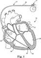
図1は、患者の体内に植え込まれたリードを有する例示的な医療機器12の概略図である。図示の例示的実施形態では、医療機器12は、体内に植え込まれたパルス発生器を備える。このパルス発生器12は、患者の心臓16に挿入されたリード14に接続される。心臓16は、右心房18と、右心室20と、左心房22と、左心室24とを含む。パルス発生器12は、体内、典型的には患者の胸部又は腹部内などの場所において皮下に植込み可能であるが、他の植込み場所も可能である。 FIG. 1 is a schematic view of an exemplary
リード14の基端部分26は、パルス発生器12に接続されていてもよく、あるいはパルス発生器12と一体的に形成されていてもよい。次に、リード14の先端部分28は、図示のように、右心室20内などの心臓16内又はその近傍の所望の場所に植込み可能である。使用に際して、リード14の先端部分28上の1つ又は複数の電極30は、心臓16への電流の形態で患者に治療を提供することができる。特定の実施形態では、たとえば電極(複数可)30を、徐脈、頻脈、又は他の心臓不整脈の治療に使用される心臓リード14の一部として設けることができる。 The
例示的な実施形態では患者の心臓16に挿入された単一のリード14のみを示しているが、別の実施形態では、心臓16の他の部位を電気的に刺激するように複数のリードを利用することができる。いくつかの実施形態では、たとえば、第2リード(図示せず)の先端部分が右心房18に植込み可能である。これに加えて、又はこれに代えて、別のリードを、心臓16の左側を刺激するために心臓16の左側の内部又はその近傍に(たとえば、冠静脈内に)植込み可能である。心外膜リードなどの他のタイプのリードも、図1に示すリード14に加えて又はその代わりに、利用することができる。 While the exemplary embodiment shows only a
動作中、リード14は、パルス発生器12と心臓16の間で電気信号を伝えるように構成することができる。たとえば、パルス発生器12がペースメーカである実施形態では、リード14を利用して、心臓16をペーシングするための治療用電気刺激を送出することができる。たとえば、徐脈又は頻脈の治療では、パルス発生器12を利用して、心臓16にペーシングパルスの形態で電気刺激を送出することができる。パルス発生器12が植込み型除細動器である他の実施形態では、リード14を利用して、心臓発作又は不整脈などのイベントに応答して心臓16に電気ショックを送出することができる。いくつかの実施形態では、パルス発生器12はペーシング機能と除細動機能の両方を含む。 In operation, the
パルス発生器12がMRIスキャナ又は他の外部磁気源からの磁場を受けると、電磁放射線が体内で生成される。電磁放射線は、リード14によって検出されて、体組織と接触するリード電極(複数可)30に伝達され得る。この電磁放射線は、リード電極(複数可)30と体組織の境界面で加熱を生じさせる可能性があり、リード14を介してパルス発生器12によって伝送される治療用電流に干渉する可能性がある。 When the
図2は、図1のリード14に対する簡略化した等価回路32を示す概略図であり、MRIスキャナによって生成されたRF電磁エネルギーからの、リード14で検出されるRFエネルギーを表す。図2に示すように、回路32のVi34は、MRIスキャナからの、リード14によって検出される等価なエネルギー源を表す。磁気共鳴撮像中に、リード14の長さはアンテナに類似する機能を果たし、MRIスキャナから身体に伝送されたRFエネルギーを受け取る。図2の電圧(Vi)34はたとえば、リード14によって受け取られる、RFエネルギーから生じる電圧を表し得る。リード14によって検出されたRFエネルギーはたとえば、MRIスキャナによって生成された回転するRF磁場から生じることができ、伝導組織内の回転する磁場ベクトルに垂直な面において電場を発生させる。これらの電場の接線成分をリード14の長さに沿ってつなぎ合わせるとリード14になる。したがって、電圧(Vi)34は、リード14の長さに沿った接線方向の電場の積分(すなわち、電場の線積分)に等しい。 FIG. 2 is a schematic diagram illustrating a simplified equivalent circuit 32 for the
回路32のZlパラメータ36は、MRIスキャナのRF周波数におけるリード14によって示される等価なインピーダンスを表す。インピーダンス値Zl36はたとえば、1.5テスラMRIスキャナでは64MHzのRF周波数において、又は3テスラMRIスキャナでは128MHzのRF周波数においてリード14によって示される、並列インダクタンス及びコイルの巻回部ごとの静電容量から生じるインダクタンス又は等価なインピーダンスを表し得る。リード14のインピーダンスZlは、実部(すなわち、抵抗)及び虚部(すなわち、リアクタンス)を有する複素数である。 The
回路32のZb38は、リードの接点における体組織のインピーダンスを表し得る。次に、Zc40は、リード14の長さに沿った周囲の体組織へのリード14の容量結合を表すことができ、これによって、MRIスキャナのRF周波数において高周波電流(エネルギー)が周囲組織に漏洩する経路が形成され得る。吸収されるエネルギー(源Vi34によって表される)を最小にすることによって、リードの体組織との接点において体組織に伝達されるエネルギーが減る。
さらに図2に示すように、リード14は、MRIスキャナのRF周波数において周囲組織へのいくらかの量の漏洩40を有する。符号38によってさらに示されるように、リード電極(複数可)30の心臓16内の体組織への接点におけるインピーダンスもある。その結果生じる、体組織に加えられる電圧Vbは、以下の式に関連づけることができる。 As further shown in FIG. 2, the
Vb=Vi Zbe/(Zbe+Zl) (式中、Zbe=Zcと並列なZb)
典型的には、周囲組織に対して接触がなされるリード14の先端の温度は、符号38において(すなわち、「Zb」において)消散される電力に部分的には関連し、該電力はVbの二乗に関連する。したがって、符号38において消散される電力から生じる温度上昇を最小にするために、リード14のインピーダンスZl(36)を最大にしながらVi(34)及びZc(40)を最小にすることが望ましい。いくつかの実施形態では、リード14のインピーダンスZl(36)は、MRIスキャナのRF周波数において増大可能であり、これは、接点38において周囲の体組織に消散されるエネルギーを減らす助けとなる。Vb = Vi Zbe / (Zbe + Zl) (where Zbe = Zb in parallel with Zc)
Typically, the temperature at the tip of the
いくつかの実施形態では、リード14のインピーダンスは、リード14にインダクタンスを追加することによって、かつ/又は適切な構築技術によって、増大させることができる。たとえば、リード14のインダクタンスは、導体コイル(複数可)の直径を増大させることによって、かつ/又は電極(複数可)30に電気エネルギーを供給するために使用される導体コイル(複数可)のピッチを減少させることによって、増大させることができる。コイルピッチを減少させると、コイルの連続する巻回部間の静電容量(すなわち、コイル巻回部ごとの静電容量)を増大させることができる。(コイルのらせん形状からの)インダクタンスと巻回部ごとの静電容量を並列に組み合わせると、共振回路が構成される。らせんコイル状のリード構造では、リードの共振周波数がMRIのRF周波数を上回る場合、らせん形コイルはインダクタとして作用する。インダクタでは、コイル領域の断面積を増大させることにより、かつ/又はコイルピッチを減少させることにより、インダクタンスが増大し、その結果、リード14のインピーダンスが増大する。 In some embodiments, the impedance of the
アンテナと同様に、リードからのエネルギー検出は、対象となる周波数の波長に対するその共振長さに関連する。たとえば、ダイポールアンテナでは、アンテナ長が波長の半分又は波長の整数倍のときに、アンテナが同調状態、すなわち共振状態であると考えられる。共振長さにおいて、アンテナのエネルギー検出は最大になる。同様に、また、いくつかの実施形態では、リード14は、リード14内での共振を防ぎ、したがって電圧Viを最小にするように離調状態とすることができる。図1に示す例示的な実施形態では、たとえば、リード14は、長さL = 整数 x λ/2において共振周波数を有するアンテナとして機能する。いくつかの実施形態では、波長に影響を及ぼすリード14の長さ及び/又はリード14の構造パラメータは、リード14内の共振を回避するように選定可能である。 As with antennas, energy detection from the lead is related to its resonant length for the wavelength of interest frequency. For example, in a dipole antenna, when the antenna length is half the wavelength or an integral multiple of the wavelength, the antenna is considered to be in a tuning state, that is, a resonance state. At the resonance length, the energy detection of the antenna is maximized. Similarly, and in some embodiments, the
いくつかの実施形態では、MRIによって誘導されるRFエネルギーの波長に対してリード14の長さを離調するように変更する(detuning)ことに加えて、シールドをリード14に付加してリード14から検出される電磁エネルギーの量をさらに減らすこともできる。たとえば、シールドから検出されたエネルギーはリード14の長さに沿って患者の身体に付与され、このエネルギーがリード先端に付与されることを防ぐことができる。シールド/リードの長さに沿って遮蔽することによって妨害されたエネルギーの伝達はまた、シールド構造に抵抗材料を使用してエネルギーを抵抗性の損失として消散することによって阻止することができる。 In some embodiments, in addition to detuning the length of
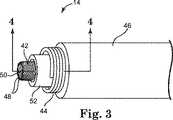
図3は、例示的な実施形態による図1のリード14の内部構造を示す図である。図3の実施形態では、リード14は、内側電極導体ワイヤ42と、外側電極導体ワイヤ44と、該外側電極導体ワイヤ44のまわりに径方向に配置された絶縁層46とを含む。内側導体ワイヤ42は、当技術分野で知られている任意の数の異なる構成を有することができる。この構成には、コイル状構成、ケーブル構成、直線ワイヤ構成などが含まれるが、これらに限定されるものではない。 FIG. 3 is a diagram illustrating the internal structure of the
図3の例示的な実施形態では、内側導体ワイヤ42はらせん形状の多糸線コイル導体ワイヤからなり、この導体ワイヤは、リード14を介して電気刺激エネルギーを送出するために使用される内側電極を形成するために共にきつく巻き付けられるいくつかの糸線ストランド48を有する。一実施形態では、たとえば、内側導体ワイヤ42は、らせん形状の導体を形成する6本以上の糸線ストランド48を含む。別の実施形態では、内側導体ワイヤ42は、これより多い又は少ない数の糸線ストランド48を含むことができる。一実施形態では、たとえば、内側導体ワイヤ42は、共に径方向に巻き付けられた12本の糸線ストランド48を含むことができる。いくつかの実施形態では、内側導体ワイヤ42を形成する糸線ストランド48のそれぞれは、断面積当たり約10%〜28%の銀含有率を有する銀充填MP35Nワイヤからなることができる。 In the exemplary embodiment of FIG. 3, the
いくつかの実施形態では、内側導体ワイヤ42は、中空構成を有し、内部管腔50を含む。内部管腔50は、ワイヤ42を通って延び、体内でリード14の植込みを促進するために使用可能なスタイレット又はガイドワイヤを受け入れるように適合される。特定の実施形態では、内側導体ワイヤ42は、管腔50に挿入されるべきスタイレット又はガイドワイヤの直径より若干大きい直径を有するマンドレルのまわりにいくつかのワイヤ糸線を共に径方向に巻き付けることによって製造することができる。ワイヤ42のトルク特性を改善するために、ワイヤ糸線48は、糸線ストランド48同士の間に間隙又は空間が存在しないように、ワイヤ42の製造中に一緒に緊密に巻き付けることができる。 In some embodiments, the
さらに図3に示すように、また、いくつかの実施形態では、外側導体ワイヤ44は、内側導体ワイヤ42のまわりに同軸状に配置され、リード14の長さの全部又は一部に沿って延びるらせんコイル構成を有する。いくつかの実施形態では、外側導体ワイヤ44は、巻き付けられた単一のワイヤから形成される単一糸線構造を有する。別の実施形態では、外側導体44は、共に径方向に巻き付けられた複数のワイヤ糸線から形成される多糸線構造を有する。一実施形態では、たとえば、外側導体ワイヤ44は、共に径方向に巻き付けられた2つのワイヤ糸線から形成される二重糸線構造を有する。 As further shown in FIG. 3, and in some embodiments, the
外側導体ワイヤ44を内側導体ワイヤ42から径方向に離間して配置し、外側導体ワイヤ44を内側導体ワイヤ42から電気的に絶縁してもよい。いくつかの実施形態では、たとえば、外側導体ワイヤ44は、リード14が多極リードとして機能することができるように、内側導体ワイヤ42から電気的に絶縁される。特定の実施形態では、内側導体ワイヤ42と外側導体ワイヤ44の間に置かれた第2絶縁層52がさらに用いられて、導体ワイヤ42、44を互いから電気的に絶縁する。いくつかの実施形態では、たとえば、第2絶縁層52は、シリコン、ポリウレタン、又は他の好適なポリマー材料で作製されたシースを含んでいてもよい。 The
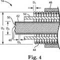
図4は、リード14の、図3の4−4線における断面図である。さらに図4に示すように、また、いくつかの実施形態では、外側導体ワイヤ44は、ワイヤ44の有効ピッチを減少させるために直径の小さなワイヤで形成され、それによりワイヤ44のインダクタンスを増大させる。いくつかの実施形態では、たとえば、外側導体ワイヤ44のワイヤ径D1は、約0.0254〜0.1524mm(0.001〜0.006インチ)の範囲、より具体的には約0.0762〜0.1016mm(0.003〜0.004インチ)の範囲にある。ただし、外側導体ワイヤ44のワイヤ径D1は、用いられるリードのタイプ、リードの構成、ならびに他の要因に応じて、これより大きくても小さくてもよい。外側導体ワイヤ44の直径D1が比較的小さいため、これより大きなワイヤ径を有する従来のリードに比べて、リード14の長さに沿って存在するコイルの巻き数が多く、このため導体ワイヤ44のインピーダンスが増大する。インピーダンスがこのように増大することは、リード電極(複数可)30において又はその近傍において周囲の体組織に消散されるエネルギーを減らすことを支援する。4 is a cross-sectional view of the
外側導体ワイヤ44の全径D2も、ワイヤ44のインダクタンスをさらに増大させるために増加させることができる。いくつかの実施形態では、たとえば、外側導体ワイヤ44の全径D2は、約1.2954〜1.7272mm(0.051〜0.068インチ)の範囲、より具体的には約1.3462〜1.6764mm(0.053〜0.066インチ)の範囲にある。ただし、外側導体ワイヤ44の全径は、用いられるリードのタイプ、リードの構成、ならびに他の要因に応じて、これより大きくても小さくてもよい。いくつかの実施形態では、リード14の全径は、約3〜7Fr、より具体的には約5〜6Frの範囲にある。Overall diameter D2 of the
いくつかの実施形態では、外側導体ワイヤ44は、低抵抗性の金属又はMP35Nなどの金属合金からなる外側管状層に銀などの導電性材料からなる内側コアを充填した延伸充填管(drawn−filled tube)で形成される。この管は、充填及び延伸された後、当技術分野で知られている従来技術を使用して、らせん形状に巻かれてリード14に取り付けられる。一実施形態では、外側導体ワイヤ44は、断面積当たり約28%の銀含有率を有する銀充填MP35Nワイヤからなる。上述したように、使用に際して、ワイヤ44に付与される抵抗の増加については、外側導体ワイヤ44の一部を形成する外側管状金属又は金属合金の抵抗が比較的低いことを利用して、より小さい直径のワイヤを使用することで補うことができる。いくつかの実施形態では、外側導体ワイヤ44を形成する1つ又は複数の材料は、ワイヤ44により高い可撓性を付与するように選択されてもよい。 In some embodiments, the
外側導体ワイヤ44は、MRI処置中に受けるRF電磁エネルギーを消散することを支援するように外側導体ワイヤ44により大きな抵抗を付与するために、内側導体ワイヤ42とは異なる1つ又は複数の材料で形成することができる。一実施形態では、たとえば、外側導体ワイヤ44を形成するワイヤ糸線は、約28%の銀含有率(断面積当たり)を有する銀充填MP35N材料を含むことができるのに対し、内側導体ワイヤ42を形成するワイヤ糸線は、28%より低い銀含有率(断面積当たり)を有することができる。 The
さらに図4に示すように、また、いくつかの実施形態では、内側導体ワイヤ42は、約0.0254〜0.1016mm(0.001〜0.004インチ)、より具体的には約0.0508mm(0.002インチ)のワイヤ径D3を有する。特定の実施形態では、内側導体ワイヤ42の外径D4は、約0.508〜0.7112mm(0.020〜0.028インチ)、より具体的には約0.5588〜0.5842mm(0.022〜0.023インチ)である。なお、ワイヤ径D3及び外径D4を含む内側導体ワイヤ42の寸法は、変更することができる。As further shown in FIG. 4, and in some embodiments, the
リード14のインダクタンス、特に外側導体ワイヤ44のインダクタンスを増大させることによって、リード14は、磁気共鳴映像法の処置中に受けるRF電磁エネルギーを消散するように構成される。電磁エネルギーがこのように消散すると、電極(複数可)30の位置における体組織の加熱が減少することとなる。リード14のインダクタンスが増大すると、リード14を介して送出される治療用電流に対する電磁エネルギーの影響も減少し、場合によっては、リード14がMRI処置中に治療の提供を継続することが可能になる。いくつかの実施形態では、たとえば、リード14のインダクタンスが増大すると、リード14は、MRI周波数では弱いアンテナとして作用しながら、機器の通常周波数(たとえば、0.5Hz〜500Hz)で機能することができる。 By increasing the inductance of the
例示的なリード14は、患者の心臓16にペーシングを提供する際に使用される心臓リードに関して説明されているが、リード14の構造は、電磁場の存在下で動作する他の医療機器にも適用することができる。たとえば、内側及び外側導体ワイヤ42、44を含めて、リード14の構造は、MRI撮像を利用する神経学的な適用例で使用するように適合された神経リードで使用することができる。 Although the
本発明の範囲から逸脱することなく、説明された例示的な実施形態に種々の改変及び付加をなすことができる。たとえば、上述した実施形態は特定の特徴について言及しているが、本発明の範囲は、特徴のさまざまな組み合わせを有する実施形態、及び説明された特徴のすべてを含むわけではない実施形態も含む。したがって、本発明の範囲は、特許請求の範囲とそのすべての均等物に含まれるかかるすべての代替形態、改変形態、及び変形形態を包含するものである。 Various modifications and additions may be made to the described exemplary embodiments without departing from the scope of the present invention. For example, although the embodiments described above refer to particular features, the scope of the invention includes embodiments having various combinations of features, as well as embodiments that do not include all of the described features. Accordingly, the scope of the invention is intended to embrace all such alternatives, modifications and variations that fall within the scope of the claims and all equivalents thereof.
Claims (15)
Translated fromJapanese前記リードの長さの全部又は一部に沿ってらせん状に配置されており、共に径方向に巻き付けられそれぞれが銀充填MP35N材料から形成された6本以上のワイヤ糸線を含む中空の多糸線構成を有する内側電極導体ワイヤと、
前記リードの長さの全部又は一部に沿って前記内側電極導体ワイヤのまわりにらせん状に配置され、かつ該内側電極導体ワイヤから離間して配置される外側電極導体ワイヤであって、単一又は二重の糸線構成を有し、外側電極導体ワイヤの各ワイヤ糸線が、前記内側電極導体ワイヤの各糸線よりも多い銀含有率を有する銀充填MP35N材料から形成される、外側電極導体ワイヤと、
前記内側電極導体ワイヤのまわりに径方向に配置された少なくとも1つの絶縁層と
を備え、前記外側電極導体ワイヤが、磁気共鳴映像法の処置中に前記リードが受けた電磁エネルギーを消散するように構成される、医療用リード。An implantable medical lead,
A hollow multi-filament comprising six or more wire strands that are helically disposed along all or part of the length of the lead, both wound in the radial direction, each formed from a silver-filled MP35N material An inner electrode conductor wire having a wire configuration;
An outer electrode conductor wire that is helically disposed about the inner electrode conductor wire along all or part of the length of the lead and is spaced apart from the inner electrode conductor wire; Or an outer electrode having a double thread configuration, wherein each wire thread of the outer electrode conductor wire is formed from a silver filled MP35N material having a higher silver content than each thread of the inner electrode conductor wire A conductor wire;
At least one insulating layer disposed radially around the inner electrode conductor wire, such that the outer electrode conductor wire dissipates electromagnetic energy received by the lead during a magnetic resonance imaging procedure Composed medical lead.
前記外側電極導体ワイヤのまわりに配置された第1絶縁層と、
前記外側電極導体ワイヤと前記内側電極導体ワイヤの間に配置された第2絶縁層とを備える、請求項1乃至9のいずれか一項に記載の医療用リード。The at least one insulating layer comprises:
A first insulating layer disposed around the outer electrode conductor wire;
The medical lead according to any one of claims 1 to 9, further comprising a second insulating layer disposed between the outer electrode conductor wire and the inner electrode conductor wire.
前記パルス発生器に電気的に接続されるリードであって、該リードの長さの全部又は一部に沿ってらせん状に配置されており、共に径方向に巻き付けられた6本以上のワイヤ糸線を含む中空の多糸線構成を有する内側電極導体ワイヤを含むリードと、
前記リードの長さの全部又は一部に沿って前記内側電極導体ワイヤのまわりにらせん状に配置され、かつ該内側電極導体ワイヤから離間して配置される外側電極導体ワイヤであって、単一又は二重のワイヤ糸線構成を有し、外側電極導体ワイヤの各ワイヤ糸線が、前記内側電極導体ワイヤの各ワイヤ糸線よりも多い銀含有率を有する銀充填MP35N材料で形成される、外側電極導体ワイヤと、
前記内側電極導体ワイヤのまわりに径方向に配置された少なくとも1つの絶縁層と
を備え、前記外側電極導体ワイヤが、磁気共鳴映像法の処置中に前記リードが受けた電磁エネルギーを消散するように構成される、医療機器。A pulse generator;
6 or more wire yarns electrically connected to the pulse generator, arranged in a spiral along all or part of the length of the lead, and wound together in the radial direction A lead comprising an inner electrode conductor wire having a hollow multifilament configuration comprising a wire;
An outer electrode conductor wire that is helically disposed about the inner electrode conductor wire along all or part of the length of the lead and is spaced apart from the inner electrode conductor wire; Or having a double wire strand configuration, wherein each wire strand of the outer electrode conductor wire is formed of a silver filled MP35N material having a higher silver content than each wire strand of the inner electrode conductor wire. An outer electrode conductor wire;
At least one insulating layer disposed radially around the inner electrode conductor wire, such that the outer electrode conductor wire dissipates electromagnetic energy received by the lead during a magnetic resonance imaging procedure Configured medical device.
Applications Claiming Priority (3)
| Application Number | Priority Date | Filing Date | Title |
|---|---|---|---|
| US2666108P | 2008-02-06 | 2008-02-06 | |
| US61/026,661 | 2008-02-06 | ||
| PCT/US2009/032838WO2009100003A1 (en) | 2008-02-06 | 2009-02-02 | Lead with mri compatible design features |
Publications (2)
| Publication Number | Publication Date |
|---|---|
| JP2011509813A JP2011509813A (en) | 2011-03-31 |
| JP5149399B2true JP5149399B2 (en) | 2013-02-20 |
Family
ID=40521968
Family Applications (1)
| Application Number | Title | Priority Date | Filing Date |
|---|---|---|---|
| JP2010544485AExpired - Fee RelatedJP5149399B2 (en) | 2008-02-06 | 2009-02-02 | Lead with design features compatible with MRI |
Country Status (6)
| Country | Link |
|---|---|
| US (2) | US8244346B2 (en) |
| EP (1) | EP2249920B1 (en) |
| JP (1) | JP5149399B2 (en) |
| CN (1) | CN101925379B (en) |
| AU (1) | AU2009212697B2 (en) |
| WO (1) | WO2009100003A1 (en) |
Families Citing this family (58)
| Publication number | Priority date | Publication date | Assignee | Title |
|---|---|---|---|---|
| US7610101B2 (en) | 2006-11-30 | 2009-10-27 | Cardiac Pacemakers, Inc. | RF rejecting lead |
| WO2009076169A2 (en)* | 2007-12-06 | 2009-06-18 | Cardiac Pacemakers, Inc. | Implantable lead with shielding |
| AU2008335462B2 (en)* | 2007-12-06 | 2014-02-20 | Cardiac Pacemakers, Inc. | Implantable lead having a variable coil conductor pitch |
| US8275464B2 (en) | 2007-12-06 | 2012-09-25 | Cardiac Pacemakers, Inc. | Leads with high surface resistance |
| WO2009100003A1 (en) | 2008-02-06 | 2009-08-13 | Cardiac Pacemakers, Inc. | Lead with mri compatible design features |
| WO2009134901A1 (en)* | 2008-04-30 | 2009-11-05 | Medtronic, Inc. | Magnetic resonance imaging shunt electrodes with self-healing coatings |
| US8103360B2 (en)* | 2008-05-09 | 2012-01-24 | Foster Arthur J | Medical lead coil conductor with spacer element |
| US8178318B2 (en) | 2008-08-06 | 2012-05-15 | Praxair Technology, Inc. | Method for controlling pH, osmolality and dissolved carbon dioxide levels in a mammalian cell culture process to enhance cell viability and biologic product yield |
| US8335570B2 (en) | 2008-10-09 | 2012-12-18 | Boston Scientific Neuromodulation Corporation | Electrical stimulation leads having RF compatibility and methods of use and manufacture |
| US8644951B1 (en)* | 2009-12-02 | 2014-02-04 | University Of Central Florida Research Foundation, Inc. | Medical devices having MRI compatible metal alloys |
| US9084883B2 (en)* | 2009-03-12 | 2015-07-21 | Cardiac Pacemakers, Inc. | Thin profile conductor assembly for medical device leads |
| ES2547713T3 (en)* | 2009-06-26 | 2015-10-08 | Cardiac Pacemakers, Inc. | Bypass of a medical device that includes a single-coil coil with improved torque transmission capacity and reduced RM heating |
| US8335572B2 (en) | 2009-10-08 | 2012-12-18 | Cardiac Pacemakers, Inc. | Medical device lead including a flared conductive coil |
| US9254380B2 (en) | 2009-10-19 | 2016-02-09 | Cardiac Pacemakers, Inc. | MRI compatible tachycardia lead |
| WO2011053199A1 (en)* | 2009-10-30 | 2011-05-05 | St. Jude Medical Ab | A medical implantable lead |
| US9014815B2 (en)* | 2009-11-19 | 2015-04-21 | Medtronic, Inc. | Electrode assembly in a medical electrical lead |
| US8306630B2 (en)* | 2009-12-30 | 2012-11-06 | Cardiac Pacemakers, Inc. | Apparatus to selectively increase medical device lead inner conductor inductance |
| US9750944B2 (en) | 2009-12-30 | 2017-09-05 | Cardiac Pacemakers, Inc. | MRI-conditionally safe medical device lead |
| JP2013512071A (en)* | 2009-12-31 | 2013-04-11 | カーディアック ペースメイカーズ, インコーポレイテッド | MRI safe and multipolar active fixed stimulation lead with colloidal structure |
| WO2011081713A1 (en) | 2009-12-31 | 2011-07-07 | Cardiac Pacemakers, Inc. | Mri conditionally safe lead with multi-layer conductor |
| US8391994B2 (en) | 2009-12-31 | 2013-03-05 | Cardiac Pacemakers, Inc. | MRI conditionally safe lead with low-profile multi-layer conductor for longitudinal expansion |
| US8818509B2 (en) | 2010-02-11 | 2014-08-26 | Biotronik Se & Co. Kg | Implantable element and electronic implant |
| WO2011103444A1 (en) | 2010-02-19 | 2011-08-25 | Cardiac Pacemakers, Inc. | Lead including conductors configured for reduced mri-induced currents |
| US9126031B2 (en) | 2010-04-30 | 2015-09-08 | Medtronic, Inc. | Medical electrical lead with conductive sleeve head |
| US8825181B2 (en) | 2010-08-30 | 2014-09-02 | Cardiac Pacemakers, Inc. | Lead conductor with pitch and torque control for MRI conditionally safe use |
| US8630718B2 (en)* | 2010-11-18 | 2014-01-14 | Cardiac Pacemakers, Inc. | Insulative structure for MRI compatible leads |
| US8509915B2 (en)* | 2010-12-17 | 2013-08-13 | Biotronik Se & Co. Kg | Implantable electrode line device for reducing undesirable effects of electromagnetic fields |
| US8433408B2 (en)* | 2011-04-27 | 2013-04-30 | Medtronic, Inc. | Pacing in the presence of electromagnetic interference |
| CN102327668B (en)* | 2011-08-12 | 2014-01-22 | 清华大学 | Implanted bioelectrode and medical assembly comprising same |
| CN103093865B (en) | 2011-10-28 | 2015-06-03 | 清华大学 | Pacemaker electrode line and pacemaker |
| CN103093858B (en)* | 2011-10-28 | 2016-10-19 | 清华大学 | Pacemaker lead and pacemaker |
| CN103093860B (en)* | 2011-10-28 | 2016-04-13 | 清华大学 | Pacing lead and pacemaker |
| CN103083808B (en) | 2011-10-28 | 2016-04-27 | 清华大学 | Pacing lead and pacemaker |
| CN103083807B (en) | 2011-10-28 | 2016-04-27 | 清华大学 | The preparation method of pacing lead |
| CN103083806B (en) | 2011-10-28 | 2016-06-08 | 清华大学 | Pacing lead and pacemaker |
| CN103093859B (en) | 2011-10-28 | 2015-08-26 | 清华大学 | Pacing lead and pacemaker |
| US8666512B2 (en) | 2011-11-04 | 2014-03-04 | Cardiac Pacemakers, Inc. | Implantable medical device lead including inner coil reverse-wound relative to shocking coil |
| CN103957979B (en)* | 2011-11-29 | 2017-09-12 | 皇家飞利浦有限公司 | For the pipe being introduced into subject |
| US20130274829A1 (en)* | 2012-04-17 | 2013-10-17 | Boston Scientific Neuromodulation Corporation | Neurostimulation device having frequency selective surface to prevent electromagnetic interference during mri |
| AU2013249088B2 (en) | 2012-04-20 | 2015-12-03 | Cardiac Pacemakers, Inc. | Implantable medical device lead including a unifilar coiled cable |
| US8954168B2 (en) | 2012-06-01 | 2015-02-10 | Cardiac Pacemakers, Inc. | Implantable device lead including a distal electrode assembly with a coiled component |
| US8666511B2 (en) | 2012-07-30 | 2014-03-04 | Medtronic, Inc. | Magnetic resonance imaging compatible medical electrical lead and method of making the same |
| US10358723B2 (en) | 2012-08-16 | 2019-07-23 | University Of Central Florida Research Foundation, Inc. | System and method for surface modification by laser diffusion |
| JP6069499B2 (en)* | 2012-08-31 | 2017-02-01 | カーディアック ペースメイカーズ, インコーポレイテッド | Lead wire with low peak MRI heating |
| CN102824689B (en) | 2012-09-07 | 2014-12-24 | 清华大学 | Implanted electrode and preparation method thereof and medical assembly comprising implanted electrode |
| US8983623B2 (en) | 2012-10-18 | 2015-03-17 | Cardiac Pacemakers, Inc. | Inductive element for providing MRI compatibility in an implantable medical device lead |
| US10501929B2 (en) | 2013-09-30 | 2019-12-10 | Drew P. HENRY | Hollow connector sleeve with interlocking components |
| WO2015123249A1 (en) | 2014-02-11 | 2015-08-20 | Cardiac Pacemakers, Inc | Rf shield for an implantable lead |
| WO2015130753A1 (en) | 2014-02-26 | 2015-09-03 | Cardiac Pacemakers, Inc | Construction of an mri-safe tachycardia lead |
| CN104083823B (en)* | 2014-06-27 | 2017-09-26 | 清华大学 | A kind of implanted electrode compatible MRI |
| CN104274902B (en)* | 2014-10-10 | 2017-09-22 | 清华大学 | The implanted electrode and its manufacture method of a kind of MRI compatible |
| US10185002B2 (en)* | 2015-06-04 | 2019-01-22 | General Electric Company | Systems and methods for MRI common mode traps |
| US20170001001A1 (en)* | 2015-07-01 | 2017-01-05 | Cardiac Pacemakers, Inc. | Left side single pass lead for la and lv sensing and pacing |
| CN105047352B (en)* | 2015-09-17 | 2017-03-22 | 中国工程物理研究院流体物理研究所 | Close-winding spiral coil and manufacturing method thereof |
| GB2559595B (en)* | 2017-02-10 | 2021-09-01 | Creo Medical Ltd | Electrosurgical apparatus and electrosurgical instrument |
| US11197612B2 (en)* | 2017-10-05 | 2021-12-14 | American University Of Beirut | Non-invasive biological, chemical markers and tracers monitoring device in blood including glucose monitoring using adaptive RF circuits and antenna design |
| CN110520042B (en)* | 2019-07-17 | 2022-05-03 | 诺尔医疗(深圳)有限公司 | deep intracranial electrodes |
| WO2021007817A1 (en)* | 2019-07-17 | 2021-01-21 | 诺尔医疗(深圳)有限公司 | Deep intracranial electrode |
Family Cites Families (188)
| Publication number | Priority date | Publication date | Assignee | Title |
|---|---|---|---|---|
| US3614692A (en)* | 1970-06-02 | 1971-10-19 | Magnetech Ind Inc | Variable induction device |
| US4135518A (en)* | 1976-05-21 | 1979-01-23 | Medtronic, Inc. | Body implantable lead and electrode |
| US4131759A (en)* | 1977-08-10 | 1978-12-26 | United States Steel Corporation | Slip sleeve mechanism for a strength tapered caged armored electromechanical cable |
| US4404125A (en)* | 1981-10-14 | 1983-09-13 | General Electric Company | Polyphenylene ether resin compositions for EMI electromagnetic interference shielding |
| US4484586A (en)* | 1982-05-27 | 1984-11-27 | Berkley & Company, Inc. | Hollow conductive medical tubing |
| GB2126466B (en) | 1982-07-01 | 1986-03-12 | Molins Plc | Conveying and uniting rod-like articles of the tobacco industry |
| US4493329A (en)* | 1982-08-19 | 1985-01-15 | Lynn Crawford | Implantable electrode having different stiffening and curvature maintaining characteristics along its length |
| US4643202A (en)* | 1985-04-15 | 1987-02-17 | Cordis Corporation | Multi-material insulation sheath for pacer lead |
| US4869970A (en) | 1986-07-14 | 1989-09-26 | Shipley Company Inc. | Radiation attenuation shielding |
| US5056516A (en)* | 1989-11-02 | 1991-10-15 | Intermedics, Inc. | Implantable endocordial lead with torque-transmitting lanyard |
| US5243911A (en) | 1990-09-18 | 1993-09-14 | Dow Robert L | Attenuator for protecting electronic equipment from undesired exposure to RF energy and/or lightning |
| US5217010A (en) | 1991-05-28 | 1993-06-08 | The Johns Hopkins University | Ecg amplifier and cardiac pacemaker for use during magnetic resonance imaging |
| US5222506A (en)* | 1991-07-29 | 1993-06-29 | Medtronic, Inc. | Implantable medical lead with electrical cross-over adaptor |
| US5246014A (en)* | 1991-11-08 | 1993-09-21 | Medtronic, Inc. | Implantable lead system |
| US5241957A (en)* | 1991-11-18 | 1993-09-07 | Medtronic, Inc. | Bipolar temporary pacing lead and connector and permanent bipolar nerve wire |
| US5231996A (en)* | 1992-01-28 | 1993-08-03 | Medtronic, Inc. | Removable endocardial lead |
| WO1993017074A1 (en)* | 1992-02-24 | 1993-09-02 | Baxter International Inc. | Polymer blends for torque transmitting catheters |
| US5447533A (en) | 1992-09-03 | 1995-09-05 | Pacesetter, Inc. | Implantable stimulation lead having an advanceable therapeutic drug delivery system |
| JPH06205842A (en)* | 1992-12-04 | 1994-07-26 | Siemens Ag | Lead assembly for implantable medical device |
| US5330522A (en)* | 1992-12-29 | 1994-07-19 | Siemens Pacesetter, Inc. | Ring electrode for a multilumen lead and method of constructing a multilumen lead |
| CA2152604C (en) | 1993-02-01 | 2000-05-09 | Thomas M. Soukup | An implantable electrode |
| US5378234A (en)* | 1993-03-15 | 1995-01-03 | Pilot Cardiovascular Systems, Inc. | Coil polymer composite |
| US5354327A (en) | 1993-04-07 | 1994-10-11 | Medtronic, Inc. | Conductor coil with specific ratio of torque to bending stiffness |
| CA2174129C (en)* | 1993-10-14 | 2004-03-09 | Sidney D. Fleischman | Electrode elements for forming lesion patterns |
| US5456707A (en)* | 1993-10-22 | 1995-10-10 | Vitatron Medical Bv | Pacing lead with improved torsion characteristics |
| JPH07178176A (en)* | 1993-12-24 | 1995-07-18 | Terumo Corp | Catheter |
| US5483022A (en)* | 1994-04-12 | 1996-01-09 | Ventritex, Inc. | Implantable conductor coil formed from cabled composite wire |
| US5618208A (en) | 1994-06-03 | 1997-04-08 | Siemens Medical Systems, Inc. | Fully insulated, fully shielded electrical connector arrangement |
| US5574249A (en) | 1994-07-18 | 1996-11-12 | Lindsay Audiophile Inc. | High resistivity inner shields for cabinets housing electronic circuitry |
| US5522875A (en)* | 1994-07-28 | 1996-06-04 | Medtronic, Inc. | Medical electrical lead system having a torque transfer stylet |
| WO1996006655A1 (en) | 1994-08-29 | 1996-03-07 | Angeion Corporation | Low profile defibrillation catheter |
| US5522872A (en)* | 1994-12-07 | 1996-06-04 | Ventritex, Inc. | Electrode-conductor sleeve joint for cardiac lead |
| US5599576A (en)* | 1995-02-06 | 1997-02-04 | Surface Solutions Laboratories, Inc. | Medical apparatus with scratch-resistant coating and method of making same |
| DE69606845T2 (en)* | 1995-04-28 | 2000-06-15 | Target Therapeutics, Inc. | High performance catheter with braided element |
| US5584873A (en)* | 1995-05-08 | 1996-12-17 | Medtronic, Inc. | Medical lead with compression lumens |
| US5728149A (en) | 1995-12-20 | 1998-03-17 | Medtronic, Inc. | Integral spiral band electrode for transvenous defibrillation leads |
| US5927345A (en) | 1996-04-30 | 1999-07-27 | Target Therapeutics, Inc. | Super-elastic alloy braid structure |
| US5800496A (en)* | 1996-06-24 | 1998-09-01 | Medtronic, Inc. | Medical electrical lead having a crush resistant lead body |
| US5810887A (en)* | 1996-08-23 | 1998-09-22 | Rhythm Technologies, Inc. | Temporary catheter |
| US5760341A (en)* | 1996-09-10 | 1998-06-02 | Medtronic, Inc. | Conductor cable for biomedical lead |
| US5968087A (en)* | 1996-12-19 | 1999-10-19 | Medtronic, Inc. | Multi-component lead body for medical electrical leads |
| EP0971767A2 (en)* | 1996-12-19 | 2000-01-19 | Medtronic, Inc. | Medical electrical lead |
| US6038472A (en)* | 1997-04-29 | 2000-03-14 | Medtronic, Inc. | Implantable defibrillator and lead system |
| US6078840A (en)* | 1997-04-30 | 2000-06-20 | Medtronic, Inc. | Medical electrical lead having improved fixation |
| US6103636A (en) | 1997-08-20 | 2000-08-15 | Micron Technology, Inc. | Method and apparatus for selective removal of material from wafer alignment marks |
| DE19736449A1 (en)* | 1997-08-21 | 1999-02-25 | Gfe Met & Mat Gmbh | Composite |
| US6249708B1 (en)* | 1997-08-26 | 2001-06-19 | Angeion Corporation | Fluted channel construction for a multi-conductor catheter lead |
| US6501994B1 (en)* | 1997-12-24 | 2002-12-31 | Cardiac Pacemakers, Inc. | High impedance electrode tip |
| US5957970A (en)* | 1998-02-18 | 1999-09-28 | Medtronic, Inc. | Method of fabricating a medical electrical lead |
| US5957966A (en) | 1998-02-18 | 1999-09-28 | Intermedics Inc. | Implantable cardiac lead with multiple shape memory polymer structures |
| US6256541B1 (en)* | 1998-04-17 | 2001-07-03 | Cardiac Pacemakers, Inc. | Endocardial lead having defibrillation and sensing electrodes with septal anchoring |
| JPH11333000A (en)* | 1998-05-27 | 1999-12-07 | Cardio Pacing Research Laboratory:Kk | Electrode lead for biological implantation |
| US6134478A (en) | 1998-06-05 | 2000-10-17 | Intermedics Inc. | Method for making cardiac leads with zone insulated electrodes |
| US7345684B2 (en) | 1998-06-25 | 2008-03-18 | Intel Corporation | Perceptually based display |
| US6208881B1 (en)* | 1998-10-20 | 2001-03-27 | Micropure Medical, Inc. | Catheter with thin film electrodes and method for making same |
| US9061139B2 (en) | 1998-11-04 | 2015-06-23 | Greatbatch Ltd. | Implantable lead with a band stop filter having a capacitor in parallel with an inductor embedded in a dielectric body |
| US8244370B2 (en)* | 2001-04-13 | 2012-08-14 | Greatbatch Ltd. | Band stop filter employing a capacitor and an inductor tank circuit to enhance MRI compatibility of active medical devices |
| US6141593A (en) | 1998-11-10 | 2000-10-31 | Intermedics Inc. | Cardiac lead with ETEE coated DBS coil |
| US6083216A (en) | 1999-01-05 | 2000-07-04 | Intermedics Inc. | Bent cardiac lead with shape memory torque coil |
| US6259954B1 (en) | 1999-02-18 | 2001-07-10 | Intermedics Inc. | Endocardial difibrillation lead with strain-relief coil connection |
| US6400992B1 (en)* | 1999-03-18 | 2002-06-04 | Medtronic, Inc. | Co-extruded, multi-lumen medical lead |
| US6813251B1 (en) | 1999-07-27 | 2004-11-02 | Intel Corporation | Split Transaction protocol for a bus system |
| US6408213B1 (en)* | 1999-09-29 | 2002-06-18 | Cardiac Pacemakers, Inc. | Low profile, ventricular, transvenous, epicardial defibrillation lead |
| US6295476B1 (en)* | 1999-11-01 | 2001-09-25 | Medtronic, Inc. | Medical lead conductor fracture visualization method and apparatus |
| US6556873B1 (en) | 1999-11-29 | 2003-04-29 | Medtronic, Inc. | Medical electrical lead having variable bending stiffness |
| US6510345B1 (en)* | 2000-04-24 | 2003-01-21 | Medtronic, Inc. | System and method of bridging a transreceiver coil of an implantable medical device during non-communication periods |
| US6516230B2 (en)* | 2000-04-26 | 2003-02-04 | Medtronic, Inc. | Medical electrical lead with fiber core |
| US7013182B1 (en)* | 2000-05-04 | 2006-03-14 | Cardiac Pacemakers, Inc. | Conductive polymer sheath on defibrillator shocking coils |
| US6850803B1 (en)* | 2000-06-16 | 2005-02-01 | Medtronic, Inc. | Implantable medical device with a recharging coil magnetic shield |
| US6501991B1 (en)* | 2000-06-21 | 2002-12-31 | Medtronic, Inc. | Electrically-isolated multiple conductor lead body |
| US6493591B1 (en)* | 2000-07-19 | 2002-12-10 | Medtronic, Inc. | Implantable active fixation lead with guidewire tip |
| US6721604B1 (en)* | 2000-07-27 | 2004-04-13 | Micronet Medical, Inc. | Reduced diameter, low resistance medical electrical lead |
| US6456888B1 (en)* | 2000-08-18 | 2002-09-24 | Cardiac Pacemakers, Inc. | Geometry for coupling and electrode to a conductor |
| US6564107B1 (en) | 2000-08-21 | 2003-05-13 | Cardiac Pacemakers, Inc. | Coil-less lead system |
| EP1336116A1 (en)* | 2000-11-24 | 2003-08-20 | Koninklijke Philips Electronics N.V. | Invasive device provided with a segmented electrical connection conductor |
| US6522920B2 (en)* | 2000-12-11 | 2003-02-18 | Pacesetter, Inc. | System and method of protecting transformer-driven switches from external magnetic fields |
| US20030063946A1 (en) | 2000-12-18 | 2003-04-03 | Janet Williams | Disposable lotion applicator |
| US20020116028A1 (en)* | 2001-02-20 | 2002-08-22 | Wilson Greatbatch | MRI-compatible pacemaker with pulse carrying photonic catheter providing VOO functionality |
| US6829509B1 (en) | 2001-02-20 | 2004-12-07 | Biophan Technologies, Inc. | Electromagnetic interference immune tissue invasive system |
| US20050283167A1 (en) | 2003-08-25 | 2005-12-22 | Biophan Technologies, Inc. | Medical device with an electrically conductive anti-antenna member |
| US6949929B2 (en)* | 2003-06-24 | 2005-09-27 | Biophan Technologies, Inc. | Magnetic resonance imaging interference immune device |
| US6854994B2 (en)* | 2001-04-19 | 2005-02-15 | Medtronic, Inc. | Medical electrical lead connector arrangement including anti-rotation means |
| US6931285B2 (en)* | 2001-04-17 | 2005-08-16 | Medtronic, Inc. | Drive shaft seal for a medical electrical lead |
| US7257449B2 (en) | 2001-05-30 | 2007-08-14 | Cardiac Pacemakers, Inc. | Extendable/retractable lead having downsized lead body |
| US6671554B2 (en)* | 2001-09-07 | 2003-12-30 | Medtronic Minimed, Inc. | Electronic lead for a medical implant device, method of making same, and method and apparatus for inserting same |
| US7904161B2 (en)* | 2001-10-22 | 2011-03-08 | Oscor Inc. | Lead adaptor having low resistance conductors and/or encapsulated housing |
| US6871091B2 (en) | 2001-10-31 | 2005-03-22 | Medtronic, Inc. | Apparatus and method for shunting induced currents in an electrical lead |
| US6944489B2 (en)* | 2001-10-31 | 2005-09-13 | Medtronic, Inc. | Method and apparatus for shunting induced currents in an electrical lead |
| US6671562B2 (en)* | 2001-11-09 | 2003-12-30 | Oscor Inc. | High impedance drug eluting cardiac lead |
| US6978185B2 (en)* | 2001-11-09 | 2005-12-20 | Oscor Inc. | Multifilar conductor for cardiac leads |
| JP2005510384A (en)* | 2001-11-22 | 2005-04-21 | ケーニツヒ ウント バウエル アクチエンゲゼルシヤフト | Use of ink in printing apparatus and printing apparatus of rotary printing press |
| US6506972B1 (en) | 2002-01-22 | 2003-01-14 | Nanoset, Llc | Magnetically shielded conductor |
| US6999821B2 (en)* | 2002-01-18 | 2006-02-14 | Pacesetter, Inc. | Body implantable lead including one or more conductive polymer electrodes and methods for fabricating same |
| US7082328B2 (en) | 2002-01-29 | 2006-07-25 | Medtronic, Inc. | Methods and apparatus for controlling a pacing system in the presence of EMI |
| US20030144718A1 (en) | 2002-01-29 | 2003-07-31 | Zeijlemaker Volkert A. | Method and apparatus for shielding coating for MRI resistant electrode systems |
| US20030144719A1 (en)* | 2002-01-29 | 2003-07-31 | Zeijlemaker Volkert A. | Method and apparatus for shielding wire for MRI resistant electrode systems |
| US6985775B2 (en)* | 2002-01-29 | 2006-01-10 | Medtronic, Inc. | Method and apparatus for shunting induced currents in an electrical lead |
| US7050855B2 (en) | 2002-01-29 | 2006-05-23 | Medtronic, Inc. | Medical implantable system for reducing magnetic resonance effects |
| EP1469910B1 (en) | 2002-01-29 | 2006-12-06 | Medtronic, Inc. | Conditioning of coupled electromagnetic signals on a lead |
| US20030144720A1 (en)* | 2002-01-29 | 2003-07-31 | Villaseca Eduardo H. | Electromagnetic trap for a lead |
| US8396568B2 (en) | 2002-04-11 | 2013-03-12 | Medtronic, Inc. | Medical electrical lead body designs incorporating energy dissipating shunt |
| US20030216800A1 (en) | 2002-04-11 | 2003-11-20 | Medtronic, Inc. | Implantable medical device conductor insulation and process for forming |
| US20030204217A1 (en) | 2002-04-25 | 2003-10-30 | Wilson Greatbatch | MRI-safe cardiac stimulation device |
| US7158837B2 (en) | 2002-07-10 | 2007-01-02 | Oscor Inc. | Low profile cardiac leads |
| US7139613B2 (en) | 2002-09-25 | 2006-11-21 | Medtronic, Inc. | Implantable medical device communication system with pulsed power biasing |
| US7292894B2 (en)* | 2002-09-27 | 2007-11-06 | Medtronic, Inc. | Methods and apparatus for joining small diameter conductors within medical electrical leads |
| US7031777B2 (en)* | 2002-09-27 | 2006-04-18 | Medtronic, Inc. | Cardiac vein lead with flexible anode and method for forming same |
| DE10249239A1 (en)* | 2002-10-23 | 2004-05-06 | Philips Intellectual Property & Standards Gmbh | Magnetic resonance imaging device with additional electrical equipment |
| US20040088033A1 (en)* | 2002-10-31 | 2004-05-06 | Smits Karel F.A.A. | Implantable medical lead designs |
| US6920361B2 (en) | 2003-02-14 | 2005-07-19 | Medtronic, Inc. | Reverse wound electrodes |
| US7001369B2 (en)* | 2003-03-27 | 2006-02-21 | Scimed Life Systems, Inc. | Medical device |
| US20040199069A1 (en) | 2003-04-02 | 2004-10-07 | Connelly Patrick R. | Device and method for preventing magnetic resonance imaging induced damage |
| US20040243210A1 (en) | 2003-05-30 | 2004-12-02 | Morgan Kevin L. | Fixation of a left heart medical lead in the coronary sinus |
| US7839146B2 (en)* | 2003-06-24 | 2010-11-23 | Medtronic, Inc. | Magnetic resonance imaging interference immune device |
| US7138582B2 (en)* | 2003-06-24 | 2006-11-21 | Medtronic, Inc. | Medical electrical lead conductor formed from modified MP35N alloy |
| US7388378B2 (en)* | 2003-06-24 | 2008-06-17 | Medtronic, Inc. | Magnetic resonance imaging interference immune device |
| US6925334B1 (en)* | 2003-08-04 | 2005-08-02 | Pacesetter, Inc. | Implantable medical lead having multiple, jointly insulated electrical conductors |
| US20050070972A1 (en) | 2003-09-26 | 2005-03-31 | Wahlstrand Carl D. | Energy shunt for producing an MRI-safe implantable medical device |
| US7765005B2 (en) | 2004-02-12 | 2010-07-27 | Greatbatch Ltd. | Apparatus and process for reducing the susceptability of active implantable medical devices to medical procedures such as magnetic resonance imaging |
| US7174220B1 (en)* | 2004-03-16 | 2007-02-06 | Pacesetter, Inc. | Construction of a medical electrical lead |
| US7877150B2 (en)* | 2004-03-30 | 2011-01-25 | Medtronic, Inc. | Lead electrode for use in an MRI-safe implantable medical device |
| US7844344B2 (en)* | 2004-03-30 | 2010-11-30 | Medtronic, Inc. | MRI-safe implantable lead |
| US8989840B2 (en) | 2004-03-30 | 2015-03-24 | Medtronic, Inc. | Lead electrode for use in an MRI-safe implantable medical device |
| US7174219B2 (en) | 2004-03-30 | 2007-02-06 | Medtronic, Inc. | Lead electrode for use in an MRI-safe implantable medical device |
| US7844343B2 (en)* | 2004-03-30 | 2010-11-30 | Medtronic, Inc. | MRI-safe implantable medical device |
| US9155877B2 (en)* | 2004-03-30 | 2015-10-13 | Medtronic, Inc. | Lead electrode for use in an MRI-safe implantable medical device |
| US20050246007A1 (en) | 2004-04-28 | 2005-11-03 | Medtronic, Inc. | Novel lead body assemblies |
| US7389148B1 (en)* | 2004-05-05 | 2008-06-17 | Pacesetter, Inc. | Electrode design for defibrillation and/or sensing capabilities |
| US20060106442A1 (en) | 2004-05-19 | 2006-05-18 | The Board Of Trustees Of The Leland Stanford Junior University | Devices and methods for treating cardiac pathologies |
| US7912552B2 (en) | 2004-07-12 | 2011-03-22 | Medtronic, Inc. | Medical electrical device including novel means for reducing high frequency electromagnetic field-induced tissue heating |
| EP1776040A4 (en) | 2004-08-09 | 2012-02-15 | Univ Johns Hopkins | IMPLANTABLE MRI-COMPATIBLE PACING AND ANTENNAS AND ASSOCIATED SYSTEMS AND METHODS |
| WO2006023700A2 (en) | 2004-08-20 | 2006-03-02 | Biophan Technologies, Inc. | Magnetic resonance imaging interference immune device |
| CN1762510A (en) | 2004-09-02 | 2006-04-26 | 巨佰-雪莱公司 | Apparatus and process for reducing the susceptability of active implantable medical devices to medical procedures such as magnetic resonance imaging |
| US7761170B2 (en)* | 2004-10-21 | 2010-07-20 | Medtronic, Inc. | Implantable medical lead with axially oriented coiled wire conductors |
| US7519432B2 (en)* | 2004-10-21 | 2009-04-14 | Medtronic, Inc. | Implantable medical lead with helical reinforcement |
| US20060089696A1 (en)* | 2004-10-21 | 2006-04-27 | Medtronic, Inc. | Implantable medical lead with reinforced outer jacket |
| US8155754B2 (en)* | 2005-01-25 | 2012-04-10 | Medtronic, Inc. | Method for fabrication of low-polarization implantable stimulation electrode |
| US8280526B2 (en)* | 2005-02-01 | 2012-10-02 | Medtronic, Inc. | Extensible implantable medical lead |
| US8825180B2 (en) | 2005-03-31 | 2014-09-02 | Medtronic, Inc. | Medical electrical lead with co-radial multi-conductor coil |
| US7853332B2 (en) | 2005-04-29 | 2010-12-14 | Medtronic, Inc. | Lead electrode for use in an MRI-safe implantable medical device |
| US8027736B2 (en) | 2005-04-29 | 2011-09-27 | Medtronic, Inc. | Lead electrode for use in an MRI-safe implantable medical device |
| CA2606824C (en) | 2005-05-04 | 2015-11-24 | Surgi-Vision, Inc. | Improved electrical lead for an electronic device such as an implantable device |
| US7571010B2 (en) | 2005-05-06 | 2009-08-04 | Cardiac Pacemakers, Inc. | Cable electrode assembly for a lead terminal and method therefor |
| US7555350B2 (en) | 2005-05-27 | 2009-06-30 | Medtronic, Inc. | Electromagnetic interference immune pacing/defibrillation lead |
| US20060293737A1 (en)* | 2005-06-22 | 2006-12-28 | Cardiac Pacemakers, Inc. | Multiple electrode implantable lead |
| TWI309423B (en) | 2005-09-29 | 2009-05-01 | Murata Manufacturing Co | Laminated coil component |
| TW200717549A (en) | 2005-10-14 | 2007-05-01 | Murata Manufacturing Co | Multiplayer coil component |
| CA2623453C (en) | 2005-10-21 | 2016-02-09 | Surgi-Vision, Inc. | Mri-safe high impedance lead systems and related methods |
| US7917213B2 (en) | 2005-11-04 | 2011-03-29 | Kenergy, Inc. | MRI compatible implanted electronic medical lead |
| US8255054B2 (en) | 2005-11-04 | 2012-08-28 | Kenergy, Inc. | MRI compatible implanted electronic medical device |
| EP1945297B1 (en) | 2005-11-11 | 2016-08-10 | Greatbatch Ltd. | Tank filters placed in series with the lead wires or circuits of active medical devices to enhance mri compatibility |
| CA2623616A1 (en) | 2005-11-29 | 2007-06-07 | Surgi-Vision, Inc. | Mri-guided localization and/or lead placement systems, related methods, devices and computer program products |
| US8060214B2 (en)* | 2006-01-05 | 2011-11-15 | Cardiac Pacemakers, Inc. | Implantable medical device with inductive coil configurable for mechanical fixation |
| US9901731B2 (en) | 2006-01-31 | 2018-02-27 | Medtronic, Inc. | Medical electrical lead having improved inductance |
| US20070179582A1 (en) | 2006-01-31 | 2007-08-02 | Marshall Mark T | Polymer reinforced coil conductor for torque transmission |
| US7509167B2 (en) | 2006-02-16 | 2009-03-24 | Cardiac Pacemakers, Inc. | MRI detector for implantable medical device |
| US9037257B2 (en) | 2006-04-07 | 2015-05-19 | Medtronic, Inc. | Resonance tuning module for implantable devices and leads |
| US8116862B2 (en) | 2006-06-08 | 2012-02-14 | Greatbatch Ltd. | Tank filters placed in series with the lead wires or circuits of active medical devices to enhance MRI compatibility |
| US7559137B2 (en)* | 2006-07-17 | 2009-07-14 | Potomac Photonics, Inc. | Method for providing electrically conductive paths in polymer tubing |
| US20110288403A1 (en) | 2006-11-09 | 2011-11-24 | Greatbatch Ltd. | Multilayer helical wave filter for mri applications |
| US7610101B2 (en)* | 2006-11-30 | 2009-10-27 | Cardiac Pacemakers, Inc. | RF rejecting lead |
| WO2008115426A1 (en)* | 2007-03-19 | 2008-09-25 | Boston Scientific Neuromodulation Corporation | Mri and rf compatible leads and related methods of operating and fabricating leads |
| ES2605170T3 (en)* | 2007-03-19 | 2017-03-13 | Boston Scientific Neuromodulation Corporation | Cable manufacturing procedures and apparatus with conductors and related flexible cable configurations |
| WO2009048652A1 (en) | 2007-10-11 | 2009-04-16 | Rentendo Corporation | Reduction of rf induced tissue heating using discrete winding patterns |
| US20090099555A1 (en) | 2007-10-11 | 2009-04-16 | Ingmar Viohl | Reduction of rf induced tissue heating using conductive surface pattern |
| AU2008335462B2 (en)* | 2007-12-06 | 2014-02-20 | Cardiac Pacemakers, Inc. | Implantable lead having a variable coil conductor pitch |
| US8275464B2 (en)* | 2007-12-06 | 2012-09-25 | Cardiac Pacemakers, Inc. | Leads with high surface resistance |
| WO2009100003A1 (en) | 2008-02-06 | 2009-08-13 | Cardiac Pacemakers, Inc. | Lead with mri compatible design features |
| US20090270956A1 (en) | 2008-04-25 | 2009-10-29 | Pacesetter, Inc. | Implantable medical lead configured for improved mri safety |
| US8103360B2 (en) | 2008-05-09 | 2012-01-24 | Foster Arthur J | Medical lead coil conductor with spacer element |
| US9399129B2 (en) | 2008-10-30 | 2016-07-26 | Pacesetter, Inc. | MRI compatible implantable medical lead and method of making same |
| EP2349453A4 (en) | 2008-10-30 | 2015-07-01 | Greatbatch Ltd | Capacitor and inductor elements physically disposed in series whose lumped parameters are electrically connected in parallel to form a bandstop filter |
| US8285396B2 (en) | 2009-01-05 | 2012-10-09 | Kenergy, Inc. | MRI compatible electrical lead for an implanted electronic medical device |
| US8996126B2 (en) | 2009-02-04 | 2015-03-31 | Greatbatch Ltd. | Composite RF current attenuator for a medical lead |
| US9084883B2 (en) | 2009-03-12 | 2015-07-21 | Cardiac Pacemakers, Inc. | Thin profile conductor assembly for medical device leads |
| WO2010114429A1 (en) | 2009-03-31 | 2010-10-07 | St. Jude Medical Ab | A medical implantable lead and a method for manufacturing of such a lead |
| ES2547713T3 (en) | 2009-06-26 | 2015-10-08 | Cardiac Pacemakers, Inc. | Bypass of a medical device that includes a single-coil coil with improved torque transmission capacity and reduced RM heating |
| US8538553B2 (en) | 2009-10-06 | 2013-09-17 | Pacesetter, Inc. | MRI compatible implantable lead |
| US8335572B2 (en) | 2009-10-08 | 2012-12-18 | Cardiac Pacemakers, Inc. | Medical device lead including a flared conductive coil |
| US9254380B2 (en) | 2009-10-19 | 2016-02-09 | Cardiac Pacemakers, Inc. | MRI compatible tachycardia lead |
| US9750944B2 (en) | 2009-12-30 | 2017-09-05 | Cardiac Pacemakers, Inc. | MRI-conditionally safe medical device lead |
| JP2013512071A (en) | 2009-12-31 | 2013-04-11 | カーディアック ペースメイカーズ, インコーポレイテッド | MRI safe and multipolar active fixed stimulation lead with colloidal structure |
| US8391994B2 (en) | 2009-12-31 | 2013-03-05 | Cardiac Pacemakers, Inc. | MRI conditionally safe lead with low-profile multi-layer conductor for longitudinal expansion |
| WO2011081713A1 (en) | 2009-12-31 | 2011-07-07 | Cardiac Pacemakers, Inc. | Mri conditionally safe lead with multi-layer conductor |
| WO2011103444A1 (en) | 2010-02-19 | 2011-08-25 | Cardiac Pacemakers, Inc. | Lead including conductors configured for reduced mri-induced currents |
| US20120016451A1 (en) | 2010-07-13 | 2012-01-19 | Roger Struve | Torque enhancement for mri-conditionally safe medical device lead |
| US8825181B2 (en) | 2010-08-30 | 2014-09-02 | Cardiac Pacemakers, Inc. | Lead conductor with pitch and torque control for MRI conditionally safe use |
| US8666512B2 (en) | 2011-11-04 | 2014-03-04 | Cardiac Pacemakers, Inc. | Implantable medical device lead including inner coil reverse-wound relative to shocking coil |
- 2009
- 2009-02-02WOPCT/US2009/032838patent/WO2009100003A1/enactiveApplication Filing
- 2009-02-02CNCN2009801029447Apatent/CN101925379B/ennot_activeExpired - Fee Related
- 2009-02-02JPJP2010544485Apatent/JP5149399B2/ennot_activeExpired - Fee Related
- 2009-02-02USUS12/364,181patent/US8244346B2/ennot_activeExpired - Fee Related
- 2009-02-02EPEP09707389.4Apatent/EP2249920B1/ennot_activeNot-in-force
- 2009-02-02AUAU2009212697Apatent/AU2009212697B2/ennot_activeCeased
- 2012
- 2012-05-07USUS13/466,064patent/US8666508B2/ennot_activeExpired - Fee Related
Also Published As
| Publication number | Publication date |
|---|---|
| US8666508B2 (en) | 2014-03-04 |
| US20120271394A1 (en) | 2012-10-25 |
| EP2249920B1 (en) | 2015-07-01 |
| US20090198314A1 (en) | 2009-08-06 |
| CN101925379B (en) | 2013-07-31 |
| EP2249920A1 (en) | 2010-11-17 |
| JP2011509813A (en) | 2011-03-31 |
| AU2009212697B2 (en) | 2011-12-01 |
| CN101925379A (en) | 2010-12-22 |
| US8244346B2 (en) | 2012-08-14 |
| AU2009212697A1 (en) | 2009-08-13 |
| WO2009100003A1 (en) | 2009-08-13 |
Similar Documents
| Publication | Publication Date | Title |
|---|---|---|
| JP5149399B2 (en) | Lead with design features compatible with MRI | |
| US8335572B2 (en) | Medical device lead including a flared conductive coil | |
| JP5165065B2 (en) | Shielded embedded lead | |
| JP5542217B2 (en) | MRI conditional and safe lead with multilayer conductor | |
| JP5430671B2 (en) | Lead wire with high surface resistance | |
| JP5399475B2 (en) | Medical lead coil conductor having spacer elements | |
| JP5671069B2 (en) | Lead and implantable medical device comprising a conductor configured for reduction of MRI induced current | |
| CN102655909B (en) | MRI-safe, multipolar active fixation stimulation leads with co-diameter construction | |
| US10092747B2 (en) | MRI compatible medical devices | |
| US8676351B2 (en) | MRI conditionally safe lead with low-profile multi-layer conductor for longitudinal expansion | |
| JP5905611B2 (en) | Implantable medical device lead with Unifilar coiled cable | |
| US20100114275A1 (en) | Implantable medical lead including winding for improved mri safety | |
| AU2012200067B2 (en) | Lead with MRI compatible design features |
Legal Events
| Date | Code | Title | Description |
|---|---|---|---|
| RD04 | Notification of resignation of power of attorney | Free format text:JAPANESE INTERMEDIATE CODE: A7424 Effective date:20120216 | |
| A131 | Notification of reasons for refusal | Free format text:JAPANESE INTERMEDIATE CODE: A131 Effective date:20120529 | |
| A521 | Request for written amendment filed | Free format text:JAPANESE INTERMEDIATE CODE: A523 Effective date:20120813 | |
| TRDD | Decision of grant or rejection written | ||
| A01 | Written decision to grant a patent or to grant a registration (utility model) | Free format text:JAPANESE INTERMEDIATE CODE: A01 Effective date:20121113 | |
| A61 | First payment of annual fees (during grant procedure) | Free format text:JAPANESE INTERMEDIATE CODE: A61 Effective date:20121129 | |
| R150 | Certificate of patent or registration of utility model | Ref document number:5149399 Country of ref document:JP Free format text:JAPANESE INTERMEDIATE CODE: R150 Free format text:JAPANESE INTERMEDIATE CODE: R150 | |
| FPAY | Renewal fee payment (event date is renewal date of database) | Free format text:PAYMENT UNTIL: 20151207 Year of fee payment:3 | |
| R250 | Receipt of annual fees | Free format text:JAPANESE INTERMEDIATE CODE: R250 | |
| R250 | Receipt of annual fees | Free format text:JAPANESE INTERMEDIATE CODE: R250 | |
| R250 | Receipt of annual fees | Free format text:JAPANESE INTERMEDIATE CODE: R250 | |
| R250 | Receipt of annual fees | Free format text:JAPANESE INTERMEDIATE CODE: R250 | |
| R250 | Receipt of annual fees | Free format text:JAPANESE INTERMEDIATE CODE: R250 | |
| LAPS | Cancellation because of no payment of annual fees |