JP5149150B2 - Method and apparatus for controlling the inner circumference of an anatomical orifice or lumen - Google Patents
Method and apparatus for controlling the inner circumference of an anatomical orifice or lumenDownload PDFInfo
- Publication number
- JP5149150B2 JP5149150B2JP2008503294AJP2008503294AJP5149150B2JP 5149150 B2JP5149150 B2JP 5149150B2JP 2008503294 AJP2008503294 AJP 2008503294AJP 2008503294 AJP2008503294 AJP 2008503294AJP 5149150 B2JP5149150 B2JP 5149150B2
- Authority
- JP
- Japan
- Prior art keywords
- instrument
- implantable device
- implant
- lumen
- spindle
- Prior art date
- Legal status (The legal status is an assumption and is not a legal conclusion. Google has not performed a legal analysis and makes no representation as to the accuracy of the status listed.)
- Expired - Fee Related
Links
- 238000000034methodMethods0.000titleclaimsdescription37
- 210000004115mitral valveAnatomy0.000claimsdescription30
- 210000002216heartAnatomy0.000claimsdescription28
- 230000007246mechanismEffects0.000claimsdescription26
- 210000003484anatomyAnatomy0.000claimsdescription25
- 230000033001locomotionEffects0.000claimsdescription24
- 238000011282treatmentMethods0.000claimsdescription24
- 239000000463materialSubstances0.000claimsdescription18
- 230000014759maintenance of locationEffects0.000claimsdescription13
- 210000003709heart valveAnatomy0.000claimsdescription10
- 208000007474aortic aneurysmDiseases0.000claimsdescription6
- 238000002513implantationMethods0.000claimsdescription6
- 210000001765aortic valveAnatomy0.000claimsdescription5
- 206010027727Mitral valve incompetenceDiseases0.000claimsdescription4
- 230000000302ischemic effectEffects0.000claimsdescription4
- 208000002223abdominal aortic aneurysmDiseases0.000claimsdescription3
- 210000000436anusAnatomy0.000claimsdescription3
- 230000002496gastric effectEffects0.000claimsdescription3
- 239000012781shape memory materialSubstances0.000claimsdescription3
- 208000008589ObesityDiseases0.000claimsdescription2
- 230000007423decreaseEffects0.000claimsdescription2
- 210000003236esophagogastric junctionAnatomy0.000claimsdescription2
- 230000004927fusionEffects0.000claimsdescription2
- 230000007257malfunctionEffects0.000claimsdescription2
- 235000020824obesityNutrition0.000claimsdescription2
- 238000009941weavingMethods0.000claimsdescription2
- 238000004873anchoringMethods0.000claims1
- 230000017531blood circulationEffects0.000claims1
- 239000006260foamSubstances0.000claims1
- 210000000936intestineAnatomy0.000claims1
- 239000003550markerSubstances0.000claims1
- 230000004962physiological conditionEffects0.000claims1
- 229910001285shape-memory alloyInorganic materials0.000claims1
- 230000001256tonic effectEffects0.000claims1
- 239000007943implantSubstances0.000description214
- 238000007493shaping processMethods0.000description39
- 210000001519tissueAnatomy0.000description35
- 238000001356surgical procedureMethods0.000description23
- 210000003238esophagusAnatomy0.000description13
- 230000006870functionEffects0.000description13
- 210000002784stomachAnatomy0.000description12
- 230000000694effectsEffects0.000description11
- 239000007787solidSubstances0.000description11
- 238000003384imaging methodMethods0.000description9
- 238000007920subcutaneous administrationMethods0.000description9
- 230000008859changeEffects0.000description7
- 238000011065in-situ storageMethods0.000description7
- 230000003014reinforcing effectEffects0.000description7
- 230000004064dysfunctionEffects0.000description6
- 230000007170pathologyEffects0.000description6
- 230000005855radiationEffects0.000description6
- 238000010992refluxMethods0.000description6
- 238000013459approachMethods0.000description5
- 210000003748coronary sinusAnatomy0.000description5
- 208000021302gastroesophageal reflux diseaseDiseases0.000description5
- 238000013175transesophageal echocardiographyMethods0.000description5
- 238000002604ultrasonographyMethods0.000description5
- 0CC(C=*=C(C1)N)C1=CChemical compoundCC(C=*=C(C1)N)C1=C0.000description4
- 230000001746atrial effectEffects0.000description4
- 239000008280bloodSubstances0.000description4
- 210000004369bloodAnatomy0.000description4
- 230000036772blood pressureEffects0.000description4
- 238000007675cardiac surgeryMethods0.000description4
- 208000037265diseases, disorders, signs and symptomsDiseases0.000description4
- 238000002594fluoroscopyMethods0.000description4
- 235000015097nutrientsNutrition0.000description4
- 230000001766physiological effectEffects0.000description4
- 210000003102pulmonary valveAnatomy0.000description4
- 238000002560therapeutic procedureMethods0.000description4
- 230000002861ventricularEffects0.000description4
- 206010002091AnaesthesiaDiseases0.000description3
- 229920004934Dacron®Polymers0.000description3
- 208000035478Interatrial communicationDiseases0.000description3
- 208000011682Mitral valve diseaseDiseases0.000description3
- 230000037005anaesthesiaEffects0.000description3
- 208000013914atrial heart septal defectDiseases0.000description3
- 206010003664atrial septal defectDiseases0.000description3
- 238000010009beatingMethods0.000description3
- 230000000994depressogenic effectEffects0.000description3
- 238000010586diagramMethods0.000description3
- 238000002592echocardiographyMethods0.000description3
- 239000004744fabricSubstances0.000description3
- 239000000835fiberSubstances0.000description3
- 210000005246left atriumAnatomy0.000description3
- 238000002595magnetic resonance imagingMethods0.000description3
- 239000002184metalSubstances0.000description3
- 208000005907mitral valve insufficiencyDiseases0.000description3
- 208000006887mitral valve stenosisDiseases0.000description3
- 230000002107myocardial effectEffects0.000description3
- 210000000056organAnatomy0.000description3
- 230000035790physiological processes and functionsEffects0.000description3
- 239000005020polyethylene terephthalateSubstances0.000description3
- 230000001225therapeutic effectEffects0.000description3
- 210000003462veinAnatomy0.000description3
- 206010061818Disease progressionDiseases0.000description2
- 208000020128Mitral stenosisDiseases0.000description2
- 208000025747Rheumatic diseaseDiseases0.000description2
- 208000002847Surgical WoundDiseases0.000description2
- 210000000683abdominal cavityAnatomy0.000description2
- 210000001367arteryAnatomy0.000description2
- 239000011324beadSubstances0.000description2
- 210000004204blood vesselAnatomy0.000description2
- 230000000747cardiac effectEffects0.000description2
- 230000002612cardiopulmonary effectEffects0.000description2
- 238000002591computed tomographyMethods0.000description2
- 230000003750conditioning effectEffects0.000description2
- 230000003247decreasing effectEffects0.000description2
- 201000010099diseaseDiseases0.000description2
- 230000005750disease progressionEffects0.000description2
- 238000006073displacement reactionMethods0.000description2
- 239000003814drugSubstances0.000description2
- 239000013013elastic materialSubstances0.000description2
- 239000012530fluidSubstances0.000description2
- 238000011902gastrointestinal surgeryMethods0.000description2
- 210000002837heart atriumAnatomy0.000description2
- 230000010247heart contractionEffects0.000description2
- 230000000642iatrogenic effectEffects0.000description2
- 230000010354integrationEffects0.000description2
- 230000003993interactionEffects0.000description2
- 210000005240left ventricleAnatomy0.000description2
- 230000007774longtermEffects0.000description2
- 238000012544monitoring processMethods0.000description2
- HLXZNVUGXRDIFK-UHFFFAOYSA-Nnickel titaniumChemical compound[Ti].[Ti].[Ti].[Ti].[Ti].[Ti].[Ti].[Ti].[Ti].[Ti].[Ti].[Ni].[Ni].[Ni].[Ni].[Ni].[Ni].[Ni].[Ni].[Ni].[Ni].[Ni].[Ni].[Ni].[Ni]HLXZNVUGXRDIFK-UHFFFAOYSA-N0.000description2
- 229910001000nickel titaniumInorganic materials0.000description2
- 239000013307optical fiberSubstances0.000description2
- 210000003540papillary muscleAnatomy0.000description2
- 229920001343polytetrafluoroethylenePolymers0.000description2
- 239000004810polytetrafluoroethyleneSubstances0.000description2
- 238000002601radiographyMethods0.000description2
- 230000002787reinforcementEffects0.000description2
- 230000002441reversible effectEffects0.000description2
- 230000000552rheumatic effectEffects0.000description2
- 208000004124rheumatic heart diseaseDiseases0.000description2
- 210000005245right atriumAnatomy0.000description2
- 210000005070sphincterAnatomy0.000description2
- 208000024891symptomDiseases0.000description2
- 229920002994synthetic fiberPolymers0.000description2
- 238000002054transplantationMethods0.000description2
- 230000002792vascularEffects0.000description2
- 230000000007visual effectEffects0.000description2
- 239000002699waste materialSubstances0.000description2
- UCTWMZQNUQWSLP-VIFPVBQESA-N(R)-adrenalineChemical compoundCNC[C@H](O)C1=CC=C(O)C(O)=C1UCTWMZQNUQWSLP-VIFPVBQESA-N0.000description1
- 229930182837(R)-adrenalineNatural products0.000description1
- 208000036764Adenocarcinoma of the esophagusDiseases0.000description1
- 208000023514Barrett esophagusDiseases0.000description1
- 208000023665Barrett oesophagusDiseases0.000description1
- 241001631457CannulaSpecies0.000description1
- 208000015121Cardiac valve diseaseDiseases0.000description1
- 208000002330Congenital Heart DefectsDiseases0.000description1
- 206010056370Congestive cardiomyopathyDiseases0.000description1
- 201000010046Dilated cardiomyopathyDiseases0.000description1
- 102000009123FibrinHuman genes0.000description1
- 108010073385FibrinProteins0.000description1
- BWGVNKXGVNDBDI-UHFFFAOYSA-NFibrin monomerChemical groupCNC(=O)CNC(=O)CNBWGVNKXGVNDBDI-UHFFFAOYSA-N0.000description1
- 208000018522Gastrointestinal diseaseDiseases0.000description1
- 206010019280Heart failuresDiseases0.000description1
- 208000001953HypotensionDiseases0.000description1
- 206010021639IncontinenceDiseases0.000description1
- 206010061216InfarctionDiseases0.000description1
- 241000755266Kathetostoma giganteumSpecies0.000description1
- 208000003430Mitral Valve ProlapseDiseases0.000description1
- 238000005481NMR spectroscopyMethods0.000description1
- 206010067171RegurgitationDiseases0.000description1
- 206010061372Streptococcal infectionDiseases0.000description1
- 208000007536ThrombosisDiseases0.000description1
- 206010046814Uterine prolapseDiseases0.000description1
- 206010046940Vaginal prolapseDiseases0.000description1
- 208000033774Ventricular RemodelingDiseases0.000description1
- 206010052428WoundDiseases0.000description1
- 208000027418Wounds and injuryDiseases0.000description1
- 230000009471actionEffects0.000description1
- 230000004913activationEffects0.000description1
- 239000000853adhesiveSubstances0.000description1
- 230000001070adhesive effectEffects0.000description1
- 238000004458analytical methodMethods0.000description1
- 206010002906aortic stenosisDiseases0.000description1
- 230000001174ascending effectEffects0.000description1
- 238000005452bendingMethods0.000description1
- 230000008901benefitEffects0.000description1
- 230000003115biocidal effectEffects0.000description1
- 230000004071biological effectEffects0.000description1
- 239000012620biological materialSubstances0.000description1
- 230000015572biosynthetic processEffects0.000description1
- 230000023555blood coagulationEffects0.000description1
- 210000001124body fluidAnatomy0.000description1
- 239000010839body fluidSubstances0.000description1
- 238000009954braidingMethods0.000description1
- 239000003795chemical substances by applicationSubstances0.000description1
- 238000004891communicationMethods0.000description1
- 239000002131composite materialSubstances0.000description1
- 208000028831congenital heart diseaseDiseases0.000description1
- 208000029078coronary artery diseaseDiseases0.000description1
- 230000006378damageEffects0.000description1
- 230000007812deficiencyEffects0.000description1
- 238000013461designMethods0.000description1
- 238000001514detection methodMethods0.000description1
- 238000003745diagnosisMethods0.000description1
- 230000008034disappearanceEffects0.000description1
- 208000035475disorderDiseases0.000description1
- 229940079593drugDrugs0.000description1
- 201000006549dyspepsiaDiseases0.000description1
- 238000005516engineering processMethods0.000description1
- 229960005139epinephrineDrugs0.000description1
- 208000028653esophageal adenocarcinomaDiseases0.000description1
- 230000002169extracardiacEffects0.000description1
- 238000001125extrusionMethods0.000description1
- 230000012953feeding on blood of other organismEffects0.000description1
- 229950003499fibrinDrugs0.000description1
- 230000004907fluxEffects0.000description1
- 210000003736gastrointestinal contentAnatomy0.000description1
- 210000001035gastrointestinal tractAnatomy0.000description1
- 208000024798heartburnDiseases0.000description1
- 238000007373indentationMethods0.000description1
- 230000007574infarctionEffects0.000description1
- 208000015181infectious diseaseDiseases0.000description1
- 230000005764inhibitory processEffects0.000description1
- 238000003780insertionMethods0.000description1
- 230000037431insertionEffects0.000description1
- 238000002608intravascular ultrasoundMethods0.000description1
- 238000001990intravenous administrationMethods0.000description1
- 208000028867ischemiaDiseases0.000description1
- 238000005304joiningMethods0.000description1
- 238000002357laparoscopic surgeryMethods0.000description1
- 238000001307laser spectroscopyMethods0.000description1
- 230000003902lesionEffects0.000description1
- 208000012866low blood pressureDiseases0.000description1
- 238000003754machiningMethods0.000description1
- 230000013011matingEffects0.000description1
- 239000007769metal materialSubstances0.000description1
- 238000002324minimally invasive surgeryMethods0.000description1
- 238000012986modificationMethods0.000description1
- 230000004048modificationEffects0.000description1
- 238000000465mouldingMethods0.000description1
- 210000003205muscleAnatomy0.000description1
- 208000031225myocardial ischemiaDiseases0.000description1
- 239000005445natural materialSubstances0.000description1
- 230000007310pathophysiologyEffects0.000description1
- 230000000149penetrating effectEffects0.000description1
- 230000002093peripheral effectEffects0.000description1
- 239000004033plasticSubstances0.000description1
- 238000002360preparation methodMethods0.000description1
- 238000004321preservationMethods0.000description1
- 230000008569processEffects0.000description1
- 230000002035prolonged effectEffects0.000description1
- 210000003492pulmonary veinAnatomy0.000description1
- 238000005086pumpingMethods0.000description1
- 238000004451qualitative analysisMethods0.000description1
- 238000004445quantitative analysisMethods0.000description1
- 230000009467reductionEffects0.000description1
- 210000005241right ventricleAnatomy0.000description1
- 238000005096rolling processMethods0.000description1
- 238000000926separation methodMethods0.000description1
- 238000012306spectroscopic techniqueMethods0.000description1
- 238000010183spectrum analysisMethods0.000description1
- 239000000126substanceSubstances0.000description1
- 239000000758substrateSubstances0.000description1
- 238000012360testing methodMethods0.000description1
- 239000003106tissue adhesiveSubstances0.000description1
- 230000009466transformationEffects0.000description1
- 210000000591tricuspid valveAnatomy0.000description1
- 210000005166vasculatureAnatomy0.000description1
- 238000012800visualizationMethods0.000description1
Images


Classifications
- A—HUMAN NECESSITIES
- A61—MEDICAL OR VETERINARY SCIENCE; HYGIENE
- A61F—FILTERS IMPLANTABLE INTO BLOOD VESSELS; PROSTHESES; DEVICES PROVIDING PATENCY TO, OR PREVENTING COLLAPSING OF, TUBULAR STRUCTURES OF THE BODY, e.g. STENTS; ORTHOPAEDIC, NURSING OR CONTRACEPTIVE DEVICES; FOMENTATION; TREATMENT OR PROTECTION OF EYES OR EARS; BANDAGES, DRESSINGS OR ABSORBENT PADS; FIRST-AID KITS
- A61F2/00—Filters implantable into blood vessels; Prostheses, i.e. artificial substitutes or replacements for parts of the body; Appliances for connecting them with the body; Devices providing patency to, or preventing collapsing of, tubular structures of the body, e.g. stents
- A61F2/02—Prostheses implantable into the body
- A61F2/24—Heart valves ; Vascular valves, e.g. venous valves; Heart implants, e.g. passive devices for improving the function of the native valve or the heart muscle; Transmyocardial revascularisation [TMR] devices; Valves implantable in the body
- A61F2/2442—Annuloplasty rings or inserts for correcting the valve shape; Implants for improving the function of a native heart valve
- A61F2/2445—Annuloplasty rings in direct contact with the valve annulus
- A—HUMAN NECESSITIES
- A61—MEDICAL OR VETERINARY SCIENCE; HYGIENE
- A61F—FILTERS IMPLANTABLE INTO BLOOD VESSELS; PROSTHESES; DEVICES PROVIDING PATENCY TO, OR PREVENTING COLLAPSING OF, TUBULAR STRUCTURES OF THE BODY, e.g. STENTS; ORTHOPAEDIC, NURSING OR CONTRACEPTIVE DEVICES; FOMENTATION; TREATMENT OR PROTECTION OF EYES OR EARS; BANDAGES, DRESSINGS OR ABSORBENT PADS; FIRST-AID KITS
- A61F2/00—Filters implantable into blood vessels; Prostheses, i.e. artificial substitutes or replacements for parts of the body; Appliances for connecting them with the body; Devices providing patency to, or preventing collapsing of, tubular structures of the body, e.g. stents
- A61F2/02—Prostheses implantable into the body
- A61F2/24—Heart valves ; Vascular valves, e.g. venous valves; Heart implants, e.g. passive devices for improving the function of the native valve or the heart muscle; Transmyocardial revascularisation [TMR] devices; Valves implantable in the body
- A61F2/2442—Annuloplasty rings or inserts for correcting the valve shape; Implants for improving the function of a native heart valve
- A61F2/2466—Delivery devices therefor
- A—HUMAN NECESSITIES
- A61—MEDICAL OR VETERINARY SCIENCE; HYGIENE
- A61F—FILTERS IMPLANTABLE INTO BLOOD VESSELS; PROSTHESES; DEVICES PROVIDING PATENCY TO, OR PREVENTING COLLAPSING OF, TUBULAR STRUCTURES OF THE BODY, e.g. STENTS; ORTHOPAEDIC, NURSING OR CONTRACEPTIVE DEVICES; FOMENTATION; TREATMENT OR PROTECTION OF EYES OR EARS; BANDAGES, DRESSINGS OR ABSORBENT PADS; FIRST-AID KITS
- A61F2/00—Filters implantable into blood vessels; Prostheses, i.e. artificial substitutes or replacements for parts of the body; Appliances for connecting them with the body; Devices providing patency to, or preventing collapsing of, tubular structures of the body, e.g. stents
- A61F2/02—Prostheses implantable into the body
- A61F2/24—Heart valves ; Vascular valves, e.g. venous valves; Heart implants, e.g. passive devices for improving the function of the native valve or the heart muscle; Transmyocardial revascularisation [TMR] devices; Valves implantable in the body
- A61F2/2472—Devices for testing
- A—HUMAN NECESSITIES
- A61—MEDICAL OR VETERINARY SCIENCE; HYGIENE
- A61B—DIAGNOSIS; SURGERY; IDENTIFICATION
- A61B17/00—Surgical instruments, devices or methods
- A61B17/12—Surgical instruments, devices or methods for ligaturing or otherwise compressing tubular parts of the body, e.g. blood vessels or umbilical cord
- A61B17/12009—Implements for ligaturing other than by clamps or clips, e.g. using a loop with a slip knot
- A61B17/12013—Implements for ligaturing other than by clamps or clips, e.g. using a loop with a slip knot for use in minimally invasive surgery, e.g. endoscopic surgery
- A—HUMAN NECESSITIES
- A61—MEDICAL OR VETERINARY SCIENCE; HYGIENE
- A61B—DIAGNOSIS; SURGERY; IDENTIFICATION
- A61B17/00—Surgical instruments, devices or methods
- A61B17/08—Wound clamps or clips, i.e. not or only partly penetrating the tissue ; Devices for bringing together the edges of a wound
- A61B17/085—Wound clamps or clips, i.e. not or only partly penetrating the tissue ; Devices for bringing together the edges of a wound with adhesive layer
- A61B2017/086—Wound clamps or clips, i.e. not or only partly penetrating the tissue ; Devices for bringing together the edges of a wound with adhesive layer having flexible threads, filaments, laces or wires, e.g. parallel threads, extending laterally from a strip, e.g. for tying to opposing threads extending from a similar strip
- A—HUMAN NECESSITIES
- A61—MEDICAL OR VETERINARY SCIENCE; HYGIENE
- A61F—FILTERS IMPLANTABLE INTO BLOOD VESSELS; PROSTHESES; DEVICES PROVIDING PATENCY TO, OR PREVENTING COLLAPSING OF, TUBULAR STRUCTURES OF THE BODY, e.g. STENTS; ORTHOPAEDIC, NURSING OR CONTRACEPTIVE DEVICES; FOMENTATION; TREATMENT OR PROTECTION OF EYES OR EARS; BANDAGES, DRESSINGS OR ABSORBENT PADS; FIRST-AID KITS
- A61F2/00—Filters implantable into blood vessels; Prostheses, i.e. artificial substitutes or replacements for parts of the body; Appliances for connecting them with the body; Devices providing patency to, or preventing collapsing of, tubular structures of the body, e.g. stents
- A61F2/02—Prostheses implantable into the body
- A61F2/24—Heart valves ; Vascular valves, e.g. venous valves; Heart implants, e.g. passive devices for improving the function of the native valve or the heart muscle; Transmyocardial revascularisation [TMR] devices; Valves implantable in the body
- A61F2/2442—Annuloplasty rings or inserts for correcting the valve shape; Implants for improving the function of a native heart valve
- A—HUMAN NECESSITIES
- A61—MEDICAL OR VETERINARY SCIENCE; HYGIENE
- A61F—FILTERS IMPLANTABLE INTO BLOOD VESSELS; PROSTHESES; DEVICES PROVIDING PATENCY TO, OR PREVENTING COLLAPSING OF, TUBULAR STRUCTURES OF THE BODY, e.g. STENTS; ORTHOPAEDIC, NURSING OR CONTRACEPTIVE DEVICES; FOMENTATION; TREATMENT OR PROTECTION OF EYES OR EARS; BANDAGES, DRESSINGS OR ABSORBENT PADS; FIRST-AID KITS
- A61F2210/00—Particular material properties of prostheses classified in groups A61F2/00 - A61F2/26 or A61F2/82 or A61F9/00 or A61F11/00 or subgroups thereof
- A61F2210/0014—Particular material properties of prostheses classified in groups A61F2/00 - A61F2/26 or A61F2/82 or A61F9/00 or A61F11/00 or subgroups thereof using shape memory or superelastic materials, e.g. nitinol
- A—HUMAN NECESSITIES
- A61—MEDICAL OR VETERINARY SCIENCE; HYGIENE
- A61F—FILTERS IMPLANTABLE INTO BLOOD VESSELS; PROSTHESES; DEVICES PROVIDING PATENCY TO, OR PREVENTING COLLAPSING OF, TUBULAR STRUCTURES OF THE BODY, e.g. STENTS; ORTHOPAEDIC, NURSING OR CONTRACEPTIVE DEVICES; FOMENTATION; TREATMENT OR PROTECTION OF EYES OR EARS; BANDAGES, DRESSINGS OR ABSORBENT PADS; FIRST-AID KITS
- A61F2220/00—Fixations or connections for prostheses classified in groups A61F2/00 - A61F2/26 or A61F2/82 or A61F9/00 or A61F11/00 or subgroups thereof
- A61F2220/0008—Fixation appliances for connecting prostheses to the body
- A61F2220/0016—Fixation appliances for connecting prostheses to the body with sharp anchoring protrusions, e.g. barbs, pins, spikes
- A—HUMAN NECESSITIES
- A61—MEDICAL OR VETERINARY SCIENCE; HYGIENE
- A61F—FILTERS IMPLANTABLE INTO BLOOD VESSELS; PROSTHESES; DEVICES PROVIDING PATENCY TO, OR PREVENTING COLLAPSING OF, TUBULAR STRUCTURES OF THE BODY, e.g. STENTS; ORTHOPAEDIC, NURSING OR CONTRACEPTIVE DEVICES; FOMENTATION; TREATMENT OR PROTECTION OF EYES OR EARS; BANDAGES, DRESSINGS OR ABSORBENT PADS; FIRST-AID KITS
- A61F2220/00—Fixations or connections for prostheses classified in groups A61F2/00 - A61F2/26 or A61F2/82 or A61F9/00 or A61F11/00 or subgroups thereof
- A61F2220/0025—Connections or couplings between prosthetic parts, e.g. between modular parts; Connecting elements
- A61F2220/0075—Connections or couplings between prosthetic parts, e.g. between modular parts; Connecting elements sutured, ligatured or stitched, retained or tied with a rope, string, thread, wire or cable
- A—HUMAN NECESSITIES
- A61—MEDICAL OR VETERINARY SCIENCE; HYGIENE
- A61F—FILTERS IMPLANTABLE INTO BLOOD VESSELS; PROSTHESES; DEVICES PROVIDING PATENCY TO, OR PREVENTING COLLAPSING OF, TUBULAR STRUCTURES OF THE BODY, e.g. STENTS; ORTHOPAEDIC, NURSING OR CONTRACEPTIVE DEVICES; FOMENTATION; TREATMENT OR PROTECTION OF EYES OR EARS; BANDAGES, DRESSINGS OR ABSORBENT PADS; FIRST-AID KITS
- A61F2230/00—Geometry of prostheses classified in groups A61F2/00 - A61F2/26 or A61F2/82 or A61F9/00 or A61F11/00 or subgroups thereof
- A61F2230/0002—Two-dimensional shapes, e.g. cross-sections
- A61F2230/0004—Rounded shapes, e.g. with rounded corners
- A61F2230/0006—Rounded shapes, e.g. with rounded corners circular
- A—HUMAN NECESSITIES
- A61—MEDICAL OR VETERINARY SCIENCE; HYGIENE
- A61F—FILTERS IMPLANTABLE INTO BLOOD VESSELS; PROSTHESES; DEVICES PROVIDING PATENCY TO, OR PREVENTING COLLAPSING OF, TUBULAR STRUCTURES OF THE BODY, e.g. STENTS; ORTHOPAEDIC, NURSING OR CONTRACEPTIVE DEVICES; FOMENTATION; TREATMENT OR PROTECTION OF EYES OR EARS; BANDAGES, DRESSINGS OR ABSORBENT PADS; FIRST-AID KITS
- A61F2230/00—Geometry of prostheses classified in groups A61F2/00 - A61F2/26 or A61F2/82 or A61F9/00 or A61F11/00 or subgroups thereof
- A61F2230/0002—Two-dimensional shapes, e.g. cross-sections
- A61F2230/0004—Rounded shapes, e.g. with rounded corners
- A61F2230/0008—Rounded shapes, e.g. with rounded corners elliptical or oval
- A—HUMAN NECESSITIES
- A61—MEDICAL OR VETERINARY SCIENCE; HYGIENE
- A61F—FILTERS IMPLANTABLE INTO BLOOD VESSELS; PROSTHESES; DEVICES PROVIDING PATENCY TO, OR PREVENTING COLLAPSING OF, TUBULAR STRUCTURES OF THE BODY, e.g. STENTS; ORTHOPAEDIC, NURSING OR CONTRACEPTIVE DEVICES; FOMENTATION; TREATMENT OR PROTECTION OF EYES OR EARS; BANDAGES, DRESSINGS OR ABSORBENT PADS; FIRST-AID KITS
- A61F2230/00—Geometry of prostheses classified in groups A61F2/00 - A61F2/26 or A61F2/82 or A61F9/00 or A61F11/00 or subgroups thereof
- A61F2230/0002—Two-dimensional shapes, e.g. cross-sections
- A61F2230/0004—Rounded shapes, e.g. with rounded corners
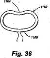
- A61F2230/0015—Kidney-shaped, e.g. bean-shaped
- A—HUMAN NECESSITIES
- A61—MEDICAL OR VETERINARY SCIENCE; HYGIENE
- A61F—FILTERS IMPLANTABLE INTO BLOOD VESSELS; PROSTHESES; DEVICES PROVIDING PATENCY TO, OR PREVENTING COLLAPSING OF, TUBULAR STRUCTURES OF THE BODY, e.g. STENTS; ORTHOPAEDIC, NURSING OR CONTRACEPTIVE DEVICES; FOMENTATION; TREATMENT OR PROTECTION OF EYES OR EARS; BANDAGES, DRESSINGS OR ABSORBENT PADS; FIRST-AID KITS
- A61F2230/00—Geometry of prostheses classified in groups A61F2/00 - A61F2/26 or A61F2/82 or A61F9/00 or A61F11/00 or subgroups thereof
- A61F2230/0063—Three-dimensional shapes
- A61F2230/0095—Saddle-shaped
- A—HUMAN NECESSITIES
- A61—MEDICAL OR VETERINARY SCIENCE; HYGIENE
- A61F—FILTERS IMPLANTABLE INTO BLOOD VESSELS; PROSTHESES; DEVICES PROVIDING PATENCY TO, OR PREVENTING COLLAPSING OF, TUBULAR STRUCTURES OF THE BODY, e.g. STENTS; ORTHOPAEDIC, NURSING OR CONTRACEPTIVE DEVICES; FOMENTATION; TREATMENT OR PROTECTION OF EYES OR EARS; BANDAGES, DRESSINGS OR ABSORBENT PADS; FIRST-AID KITS
- A61F2250/00—Special features of prostheses classified in groups A61F2/00 - A61F2/26 or A61F2/82 or A61F9/00 or A61F11/00 or subgroups thereof
- A61F2250/0004—Special features of prostheses classified in groups A61F2/00 - A61F2/26 or A61F2/82 or A61F9/00 or A61F11/00 or subgroups thereof adjustable
- A61F2250/001—Special features of prostheses classified in groups A61F2/00 - A61F2/26 or A61F2/82 or A61F9/00 or A61F11/00 or subgroups thereof adjustable for adjusting a diameter
- A—HUMAN NECESSITIES
- A61—MEDICAL OR VETERINARY SCIENCE; HYGIENE
- A61F—FILTERS IMPLANTABLE INTO BLOOD VESSELS; PROSTHESES; DEVICES PROVIDING PATENCY TO, OR PREVENTING COLLAPSING OF, TUBULAR STRUCTURES OF THE BODY, e.g. STENTS; ORTHOPAEDIC, NURSING OR CONTRACEPTIVE DEVICES; FOMENTATION; TREATMENT OR PROTECTION OF EYES OR EARS; BANDAGES, DRESSINGS OR ABSORBENT PADS; FIRST-AID KITS
- A61F2250/00—Special features of prostheses classified in groups A61F2/00 - A61F2/26 or A61F2/82 or A61F9/00 or A61F11/00 or subgroups thereof
- A61F2250/0058—Additional features; Implant or prostheses properties not otherwise provided for
- A61F2250/0082—Additional features; Implant or prostheses properties not otherwise provided for specially designed for children, e.g. having means for adjusting to their growth
Landscapes
- Health & Medical Sciences (AREA)
- Cardiology (AREA)
- Oral & Maxillofacial Surgery (AREA)
- Transplantation (AREA)
- Engineering & Computer Science (AREA)
- Biomedical Technology (AREA)
- Heart & Thoracic Surgery (AREA)
- Vascular Medicine (AREA)
- Life Sciences & Earth Sciences (AREA)
- Animal Behavior & Ethology (AREA)
- General Health & Medical Sciences (AREA)
- Public Health (AREA)
- Veterinary Medicine (AREA)
- Prostheses (AREA)
- Surgical Instruments (AREA)
- Media Introduction/Drainage Providing Device (AREA)
Description
Translated fromJapanese本発明は、一般に、外科的処置に関し、さらに詳細には、解剖学的なオリフィス又は内腔の内周を制御するための外科的処置に関する。 The present invention relates generally to surgical procedures, and more particularly to surgical procedures for controlling the inner circumference of an anatomical orifice or lumen.
哺乳類の体の多くの解剖学的な構造は、組織の壁が中央の内腔を画定する中空の通路であり、構造内を通過する血液、他の生理液、栄養物質又は廃棄物質のための導管として作用する。多数の生理学的な設定において、機能障害は、大きすぎるか又は小さすぎる構造の内腔に起因して生じる。大部分のこのようなケースにおいて、機能障害は、内腔の寸法を介在的に変化させることによって軽減することができる。 Many anatomical structures in the mammalian body are hollow passages where the wall of the tissue defines a central lumen for blood, other physiological fluids, nutrients or waste materials that pass through the structure. Acts as a conduit. In many physiological settings, dysfunction results from lumens of structures that are too large or too small. In most such cases, dysfunction can be mitigated by intervening changes in lumen dimensions.
したがって、外科手術において、オリフィス又は開口の寸法を狭くして、所望の生理学的な効果を達成するためにオリフィス又は他の開口した解剖学的な構造の内周を小さくする必要がある。しばしば、このような外科的処置は、オリフィス又は構造体を通る血液若しくは他の生理液若しくは他の構造学的な内容物の正常な生理学的な流れを中断する必要がある。所望の効果のために必要な狭くする正確な量は、オリフィス又は構造を通る生理学的な流れが再開されるまで、完全には把握できない。したがって、このような移植の後ではあるが、その場で、正常な流れの再開の後、狭くする度合いを変化させることができるように、この狭くする効果を達成する調整可能な手段を有することが有利である。 Therefore, in surgery, it is necessary to reduce the size of the orifice or opening to reduce the inner circumference of the orifice or other open anatomical structure in order to achieve the desired physiological effect. Often, such surgical procedures require disruption of the normal physiological flow of blood or other physiological fluid or other structural content through the orifice or structure. The exact amount of narrowing required for the desired effect is not fully known until physiological flow through the orifice or structure is resumed. Therefore, having such adjustable means to achieve this narrowing effect so that the degree of narrowing can be changed in situ after normal flow resumes, even after such transplantation. Is advantageous.
解剖学的な内腔内の機能障害の1つの例は、心臓の手術、特に、弁の治療における領域でのものである。一年にほぼ百万回の心臓切開手術処置が、米国内で実施されており、これらの手術のうち、20%が心臓弁に関連している。 One example of an anatomical intraluminal dysfunction is in the area of cardiac surgery, particularly in the treatment of valves. Approximately one million open heart surgery procedures are performed in the United States per year, and 20% of these surgeries are related to heart valves.
心臓外科手術の領域は、人工心肺装置の導入によって以前から変遷しており、これは、心臓切開手術を可能にする。機械的なボール弁補綴材(プロテーゼ)のさらなる導入によって心臓弁膜手術が可能になり、人工心臓弁の多数の変更及び異なる形態が開発されてきた。しかしながら、洗練された形態及び自然の心臓弁の機能を保証する理想的な人工弁は設計されていない。完全な人工心臓弁を構成することが困難な結果として、患者の自然な弁を治療することに対しての関心が増大してきた。これらの努力は、機械的な補綴材の使用と同等の長期間の耐用性が立証されており、これには、準弁膜機構を保存すること及び長期の血液凝固の抑止を回避することによるさらによい性能的な利点が加えられている。僧帽弁の治療は、今日大人の心臓手術において、最も急速に成長する分野の1つになった。 The field of cardiac surgery has been transformed with the introduction of cardiopulmonary devices, which allows for open heart surgery. With the further introduction of mechanical ball valve prostheses (prostheses), valvular surgery is possible, and numerous modifications and different forms of prosthetic heart valves have been developed. However, an ideal prosthetic valve that guarantees sophisticated morphology and natural heart valve function has not been designed. As a result of the difficulty of constructing a complete prosthetic heart valve, the patient's interest in treating the natural valve has increased. These efforts have demonstrated long-term durability equivalent to the use of mechanical prosthetics, including the preservation of quasi-valvular mechanisms and the avoidance of prolonged blood clotting inhibition. A good performance advantage has been added. Mitral valve therapy has become one of the fastest growing fields in adult cardiac surgery today.
僧帽弁の疾患は、本来的な弁の障害、及び弁の機能に最終的に影響を与える僧帽弁への外因的な病理に分類されることができる。これらの分類が存在するが、多数の治療技法及び手術全体の方法は、存在する種々の病理と同様である。 Mitral valve disease can be classified into intrinsic valve disorders and extrinsic pathologies to the mitral valve that ultimately affect the function of the valve. Although these classifications exist, a number of treatment techniques and methods of overall surgery are similar to the various pathologies that exist.
歴史的に、大部分の弁の病理は、リウマチ性の心臓病の次であり、連球菌による感染症の結果、最も一般的には僧帽弁に、次に大動脈弁に、及び最も稀に肺動脈弁に影響を与える。感染過程の結果、僧帽弁狭窄症及び大動脈狭窄症、次に、僧帽弁不全症及び大動脈瘤不全症が起こる。よりよい抗生物質の治療の出現により、リウマチの心疾患の発生が低下し、今日の発展した世界において、心臓弁障害の割合が低下している。リウマチ性の僧帽弁狭窄症の交連切開術は、先天的な心臓疾患の部門の領域外で、通常実施される僧帽弁治療の早期の例であった。しかしながら、リウマチ性の不全な弁の治療は、根底にある弁の病理及び病気の進行のために、良好な結果となっていない。 Historically, most valve pathologies are secondary to rheumatic heart disease and most commonly result in streptococcal infections, most commonly mitral, then aortic, and most rarely Affects pulmonary valve. The infection process results in mitral stenosis and aortic stenosis, followed by mitral and aortic aneurysms. With the advent of better antibiotic treatment, the incidence of rheumatic heart disease has decreased, and the rate of heart valve disorders has decreased in today's developed world. Commissural incision for rheumatic mitral stenosis was an early example of mitral valve treatment usually performed outside the field of congenital heart disease. However, treatment of rheumatic failing valves has not been successful due to the underlying valve pathology and disease progression.
リウマチ性以外の大部分の僧帽弁疾患は、一般に治療しやすい弁不全を生じる。腱索の破裂は、僧帽弁の不全の一般的な原因であり、病巣領域の逆流を生じる。歴史的には、成功して受け入れられた最初の外科治療の1つは、僧帽弁後尖の破裂する腱索のためのものであった。この治療の技術的な容易性、その再現性のある良好な結果、及びその長期の耐久性により、僧帽弁治療の分野のパイオニア的な外科医が他の弁疾患の治療を試みるようになった。 Most mitral valve diseases other than rheumatic cause valve failure that is generally treatable. Ruptured chords are a common cause of mitral valve failure and result in reflux of the focal area. Historically, one of the first successful surgical treatments was for rupturing chords of the mitral posterior leaflet. The technical ease of this treatment, its reproducible good results, and its long-term durability have led pioneering surgeons in the field of mitral valve therapy to try to treat other valve diseases. .
僧帽弁逸脱は、非常に一般的な状態であり、この場合、時間が経つにつれ、心臓不全を引き起こす。この病気において、前尖及び後尖の接合平面は、正常な弁に対して「心房化」されている。この問題は、接合平面を心室に回復することによって容易に治療されることができる。 Mitral valve prolapse is a very common condition, which causes heart failure over time. In this disease, the anterior and posterior apical junction planes are “atrialized” relative to normal valves. This problem can be easily treated by restoring the junction plane to the ventricle.
左心室内の乳頭筋は僧帽弁を支持し、その機能を補助する。乳頭筋の機能障害は、冠状動脈の疾患から梗塞又は虚血によるかによって(通常、虚血性の僧帽弁不全と称される)僧帽弁不全を生じる。僧帽弁の疾患の範囲内で、これは、弁治療における最も急速に進歩している領域である。歴史的には、重度の僧帽弁不全を有する患者のみが治療され、又は置換されるが、虚血性の僧帽弁不全が原因と考えられる並程度の不全を有する患者における弁治療を支援することに対して、外科文献における賛同者が増えている。この患者人口における早期の積極的な弁治療によって、生存者が増大し、かつ長期にわたって心室機能が改善したことが示されている。 The papillary muscle in the left ventricle supports the mitral valve and assists in its function. Papillary muscle dysfunction results in mitral valve failure (usually referred to as ischemic mitral valve failure), whether from coronary artery disease to infarct or ischemia. Within the scope of mitral valve disease, this is the most rapidly advancing area in valve therapy. Historically, only patients with severe mitral valve insufficiency are treated or replaced, but assist in valve therapy in patients with moderate insufficiency that may be caused by ischemic mitral valve insufficiency On the other hand, there is an increasing number of supporters in the surgical literature. Early aggressive valvular treatment in this patient population has been shown to increase survivors and improve ventricular function over time.
さらに、拡張型心筋症を有する患者の場合、僧帽弁不全の原因は、膨張した心室からの弁尖の接合の欠損である。その結果として起こる逆流は、弁尖の接合の欠損によるものである。これらの弁を治療する傾向が増大しつつあり、それによって、不全症を治療し、心室の形状を回復し、したがって、心室機能全体を改善する。 Furthermore, in patients with dilated cardiomyopathy, the cause of mitral valve failure is a lack of joint of the leaflets from the expanded ventricle. The resulting regurgitation is due to a loss of leaflet junction. There is an increasing tendency to treat these valves, thereby treating deficiencies and restoring ventricular shape, thus improving overall ventricular function.
僧帽弁治療の2つの基本的な特徴は、主要な弁の病理(もし存在するならば)を治すことであり、通常、リング又はバンドの形状をした補綴材を使用して環状体を支持し、又は環状体の寸法を小さくすることである。僧帽弁治療において遭遇する問題は、心臓が完全に閉鎖され、患者が心肺バイパスを切り離されるまで外科医が治療の効果を完全に評価することができないことである。これがひとたび達成されると、経食道エコー検査(TEE)を使用して弁機能は手術室で評価されることができる。重大な後遺の弁不全の所見があった場合、外科医は心臓を再び目を向け、心臓を再び開き、その後弁を再治療するか又は取り替えなければならない。これは、全体的な手術、麻酔、及びバイパスのための時間を増大し、したがって、手術の危険性全体を増大する。 The two basic features of mitral valve treatment are to cure the primary valve pathology (if present), usually using a ring or band shaped prosthesis to support the annulus Or to reduce the size of the annular body. A problem encountered in mitral valve treatment is that the surgeon cannot fully assess the effectiveness of the treatment until the heart is completely closed and the patient is disconnected from cardiopulmonary bypass. Once this is achieved, valve function can be evaluated in the operating room using transesophageal echocardiography (TEE). If there is a significant after-effect of valve failure, the surgeon must turn the heart back, reopen the heart, and then retreat or replace the valve. This increases the time for overall surgery, anesthesia, and bypass, and therefore increases the overall risk of surgery.
環状体を小さくするために使用する補綴材が理想的な寸法より大きい場合、僧帽弁不全が持続する可能性がある。補綴材が小さすぎる場合、僧帽弁狭窄症が生じる可能性がある。したがって、外科医が、最適な弁の十分性及び機能を達成するためにTEEの案内又は他の診断モダリティーのもとで鼓動を打つ心臓において、その場で環状の寸法を調整することができる調整可能な補綴材が必要となる。 Mitral valve insufficiency can persist if the prosthetic material used to reduce the annulus is larger than the ideal dimensions. If the prosthesis is too small, mitral stenosis can occur. Adjustable so that the surgeon can adjust the annular dimensions in situ in the heart beating under TEE guidance or other diagnostic modalities to achieve optimal valve sufficiency and function Need a prosthetic material.
しかし、心臓外科手術は、解剖学的なオリフィスの環状寸法がその場で調整されることが望ましい設定の1つの例である。他の例は、消化管手術の分野であり、胃腸から食道への逆流の軽減のための胃腸−食道接合部を狭くするために長期にわたって、ニッセン・フンドプリケーション処置が使用されてきた。この設定において、外科医は、従来、逆流制御を達成するために十分な狭い部分をつくることと、食道から胃への栄養分の通過を妨げる可能性のある過剰な狭さを避けることとの間にある緊張に直面する。やはり食道と胃の接合部を狭くする程度がこれら2つが競合する関心の間において最適なバランスをその場で達成するのに調整することのできる方法及び装置を有することが望ましい。 However, cardiac surgery is one example of a setting in which it is desirable that the annulus dimensions of the anatomical orifice be adjusted in situ. Another example is in the field of gastrointestinal surgery, where Nissen funding procedures have been used for a long time to narrow the gastrointestinal-esophageal junction for relief of gastrointestinal to esophageal reflux. In this setting, the surgeon has traditionally struck between creating a narrow enough section to achieve reflux control and avoiding excessive narrowing that could prevent the passage of nutrients from the esophagus to the stomach. Face a certain tension. It would also be desirable to have a method and apparatus that can be adjusted so that the degree of narrowing of the esophagus-stomach junction is optimally achieved in situ between the two competing concerns.
身体の通路の内周をその場で調整する問題とは別に、所望の受容解剖部位での補綴移植部材を配置することが医学及び手術において多くの場合必要になる。たとえば、皮下的な僧帽弁治療のために提案された既存の方法は、僧帽弁前尖を僧帽弁後尖に固定するために冠状洞又は皮下的な試みによる方法を含む。重大な医療的、論理的な問題は、これらの既存の技法の双方を伴う。冠状洞の処置の場合、冠状洞への皮下的な接近は、技術的に困難で、達成するまでに多くの時間が費やされる。この処置は、冠状洞に適切に接近するために数時間を必要とする。さらに、これらの処置は、不完全な環状リングを使用し、このリングは、それらの生理学的な効果と妥協するものである。このような処置は、典型的に、2つ以上の医療的なグレードによって僧帽弁の逆流を改良するためには効果的ではない。最終的に、管状洞の処置は、環状洞の致命的な破れ又は壊滅的な血栓症のいずれかの潜在的な惨事をもたらす。 Apart from the problem of adjusting the inner circumference of the body passage in situ, it is often necessary in medicine and surgery to place a prosthetic implant at the desired receiving anatomy. For example, existing methods proposed for subcutaneous mitral valve treatment include coronary sinus or subcutaneous attempts to secure the anterior mitral valve leaflet to the mitral valve leaflet. Serious medical and logical problems involve both of these existing techniques. In the case of coronary sinus treatment, subcutaneous access to the coronary sinus is technically difficult and takes a lot of time to achieve. This procedure requires several hours to properly approach the coronary sinus. In addition, these procedures use imperfect annular rings, which compromise with their physiological effects. Such a procedure is typically not effective for improving mitral regurgitation by more than one medical grade. Ultimately, treatment of the tubular sinus results in the potential catastrophe of either a fatal rupture of the annular sinus or a catastrophic thrombosis.
同様に、僧帽弁前尖を僧帽弁後尖に固定するために縫合、クリップ又は他の装置を使用する皮下的な処置も、治療能力に制限がある。また、このような処置は、典型的には、僧帽弁逆流の完全な治療を提供する際に不十分でもある。さらに、外科的な経験は、そのような方法が、固定された弁尖の可能性の高い分離について耐性がないものであることを示している。また、これらの処置は、虚血性の心臓の疾患において膨張した僧帽弁輪の病態生理学を解決できていない。残留している解剖学的な病理学の結果として、心室の改造又は改良された心室機能はこれらの処置に伴わない。 Similarly, subcutaneous procedures that use sutures, clips or other devices to secure the anterior mitral valve leaflet to the mitral valve leaflet have limited therapeutic capabilities. Such treatment is also typically inadequate in providing complete treatment of mitral regurgitation. In addition, surgical experience has shown that such methods are not resistant to possible separation of fixed leaflets. Also, these treatments have not resolved the pathophysiology of the dilated mitral annulus in ischemic heart disease. As a result of residual anatomical pathology, ventricular remodeling or improved ventricular function is not associated with these procedures.
したがって、これらの同じ問題のための最良の切開外科処置の成果と少なくとも等しい治療の及び生理学的な結果を達成しながら、このような例示的な環境内で切開外科手術の必要性を避け、且つ皮下又は他の最小侵入処置における僧帽弁輪のような直径を低減するための補綴移植部材の供給、配置、及び調整を可能にする供給システム及びその使用方法の必要性が存在する。 Thus, avoiding the need for open surgery within such an exemplary environment while achieving therapeutic and physiological results at least equal to the best open surgical outcome for these same problems, and There is a need for a delivery system and method of use that allows the delivery, placement, and adjustment of prosthetic implants to reduce the diameter, such as mitral annulus, in subcutaneous or other minimally invasive procedures.
前述の心臓に関する適用例は、本発明によるいくつかの適用例の単なる例示である。本発明によって予期される他の例示的な適用例は、消化管手術の分野であり、この場合、胃から食道への逆流を軽減するのに胃食道の接合部を狭くするために前述したニッセンのフンドプリケーション処置が長い間使用されてきた。この設定において、外科医は、従来、逆流制御を達成するために十分に狭い部分をつくることと、食道から胃への栄養分の通過を妨げる可能性のある過剰な狭さを避けることとの間にある緊張に直面する。さらに、「ガス・ブロート」は、げっぷを出すことを不可能にし、且つGE接合部の過剰な狭小化の一般的な合併症を引き起こすことがある。本発明による調整可能な補綴移植部材は、主要な外科的縫合の後に、生理学的な評価のもとの設定におけるその場での調整を可能にすることができる。本発明による調整可能な補綴の移植部材は、内視鏡で、皮下的に、又は身体内の体腔若しくは組織内に配置された内視鏡で、又は腹腔若しくは胸部を通す方法によって、配置されることができる。さらに、本発明によるこのような調整可能な補綴の移植部材は、移植部材が生理学的に機能している間に、遠隔の調整が移植部材に行われるように、皮下の解剖学的な組織又は身体内の他の解剖学的な組織に配置されることのできる調整手段と結合されることができる。また、この調整手段は、移植部材内に含まれて、遠隔で調整されることができる。すなわち、遠隔で制御調整される。このような調整手段は、身体から取り除くことができるか、又は後の調整のために無期限に身体内に保持されることができる。 The foregoing heart applications are merely illustrative of several applications according to the present invention. Another exemplary application envisaged by the present invention is in the field of gastrointestinal surgery, in which the Nissen described above to narrow the gastroesophageal junction to reduce reflux from the stomach to the esophagus. Fundundation procedures have been used for a long time. In this setting, the surgeon has traditionally been between creating a narrow enough section to achieve reflux control and avoiding excessive narrowing that could prevent the passage of nutrients from the esophagus to the stomach. Face a certain tension. In addition, “gas bloat” makes it impossible to burp and can cause the common complication of excessive narrowing of the GE joint. The adjustable prosthetic implant according to the present invention can allow in-situ adjustment in the original setting of the physiological assessment after the main surgical suture. The adjustable prosthetic implant according to the present invention is placed with an endoscope, subcutaneously, with an endoscope placed in a body cavity or tissue within the body, or by a method of passing through the abdominal cavity or chest. be able to. In addition, such adjustable prosthetic implants according to the present invention can be used to provide subcutaneous anatomical tissue or tissue so that remote adjustments can be made to the implant while the implant is physiologically functioning. It can be combined with adjustment means that can be placed in other anatomical tissues in the body. This adjustment means can also be included in the implant and adjusted remotely. That is, the control is adjusted remotely. Such adjustment means can be removed from the body or held in the body indefinitely for later adjustment.
内部構造又は内腔の形状及びサイズの少なくとも一方を制御するための移植可能な装置が必要とされる。移植可能な装置の寸法を調整するように構成される調整可能な部材を有する移植可能な装置がさらに必要とされる。器官がほぼ正常から正常な生理学的機能を再開する前、再開している間、及び再開した後に、調整を行う調整ツール装置に結合されるように構成される移植可能な装置がさらになお必要とされる。移植可能な装置に取り付け及び再取り付けすることができる調整ツールに結合されるように構成される移植可能な装置が必要である。 There is a need for an implantable device for controlling at least one of the internal structure or lumen shape and size. There is a further need for an implantable device having an adjustable member configured to adjust the size of the implantable device. There is still a further need for an implantable device that is configured to be coupled to an adjustment tool device that makes adjustments before, during and after the organ resumes normal to normal physiological function. Is done. There is a need for an implantable device that is configured to be coupled to an adjustment tool that can be attached and reattached to the implantable device.
[概要]
したがって、本発明の目的は、内部構造又は内腔の形状及びサイズの少なくとも一方を制御するための移植可能な装置を提供することである。[Overview]
Accordingly, it is an object of the present invention to provide an implantable device for controlling at least one of internal structure or lumen shape and size.
本発明の別の目的は、移植可能な装置の寸法を調整するように構成される調整可能な部材を有する移植可能な装置を提供することである。 Another object of the present invention is to provide an implantable device having an adjustable member configured to adjust the size of the implantable device.
本発明のさらに別の目的は、器官がほぼ正常から正常な生理学的機能を再開する前、再開している間、及び再開した後に、調整を行う調整ツール装置に結合されるように構成される移植可能な装置を提供することである。 Yet another object of the present invention is configured to be coupled to an adjustment tool device for making adjustments before, during and after the organ resumes normal to normal physiological function. It is to provide an implantable device.
本発明のさらなる目的は、移植可能な装置に取り付け及び再取り付けすることができる調整ツールに結合されるように構成される移植可能な装置を提供することである。 It is a further object of the present invention to provide an implantable device configured to be coupled to an adjustment tool that can be attached and reattached to the implantable device.
本発明のさらに別の目的は、少なくとも2次元で調整可能である移植可能な装置及び調整ツールを提供することである。 Yet another object of the present invention is to provide an implantable device and adjustment tool that is adjustable in at least two dimensions.
本発明の別の目的は、内部構造又は内腔のサイズ若しくは形状を変えることによって軽減される機能不全を有する内部構造又は内腔のための移植可能な装置を提供することである。 Another object of the present invention is to provide an implantable device for an internal structure or lumen having a malfunction that is alleviated by changing the size or shape of the internal structure or lumen.
本発明のこれら及び他の目的は、内部構造又は内腔の形状及びサイズの少なくとも一方を制御するための移植可能な装置において達成される。移植可能な装置は、移植可能な装置の寸法を調整するように構成される調整可能な部材を有する。調整ツールは、内部構造又は内腔がほぼ正常から正常な生理学的機能を再開する前、再開している間、及び再開した後に、調整可能な部材を作動させて調整を行うように構成される。 These and other objects of the present invention are achieved in an implantable device for controlling at least one of internal structure or lumen shape and size. The implantable device has an adjustable member configured to adjust the dimensions of the implantable device. The adjustment tool is configured to operate and adjust the adjustable member before, during, and after the internal structure or lumen resumes from normal to normal physiological function. .
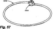
ここで、いくつかの図面を通して同じ部材に同じ符号が付されている図面を参照すると、移植部材本体15を含む例示的な移植部材10が図1に示されている。移植部材本体10は、哺乳類である患者内の意図された自然の解剖学的な受容部位の解剖学的なニーズによって決定された形状及び寸法で設けられ得る。このような自然の解剖学的な受容部位は、図示はするが、制限しないものとして、心臓弁、胃と食道との接合部近傍の食道、肛門、又はその部位の寸法及び形状を変化させ、手術後の所望の寸法及び形状を維持することができる移植部材によって軽減され得る機能不全を生じる哺乳類の体内の他の解剖学的な部位であり得る。種々の実施例において、移植部材は、大動脈弁の配置、腹部大動脈瘤装置の配置、大動脈ステント植え込み用途、大動脈エンドグラフ(endograph)用途、腹部大動脈瘤(aortic triple A)ステントグラフ、上行大動脈瘤の治療、肥満を制御するための胃での用途等に用いることができる。 Referring now to the drawings, in which like numerals refer to like parts throughout the several views, an
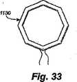
図1の移植部材10は、円形の移植部材本体15を含み、この円形の移植部材本体15は、狭い中間のネック部分を有するグロメット状の取り付け手段25と交互に介在する調整可能な波形部分20を備えている。図2及び図3で理解することができるように、移植部材本体15は、取り付け手段25の上に又はそれを通して固定された縫合糸35のような固定手段によって心臓弁30の環状体に固定されることができる。波形部分20は、移植部材本体15の周囲が短くなるか若しくは長くなると折りたたまれるか、又は拡げられる。移植部材10のその場での調整によって、心臓弁30の全体の寸法を小さくすることができ、弁尖40の接合を増大し、図2に示す形状から図3に示す形状まで形状を変化させる。 The
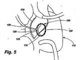
本発明のさらなる例示的な実施例100は、図4及び図5に示されており、図4には、心臓110内の心臓の開放手術による切開部105が示されており、図5には心臓切開部105を閉じた状態が示されている。図49に示すように、本発明による例示的な調整可能な移植部材100は、移植部材本体115を含み、移植部材115は、僧帽弁125の環状体に固定することのできる取り付け手段120を有する。例示的な調整可能な移植部材100は、取り付けられた又は結合された調整ツール135によって制御される調整手段130をさらに備えている。図5に示す心筋切開部105の閉鎖の後、調整ツール135は、調整手段130に取り付けられるか又は結合されたままであり、それにより心臓110を通る生理学的な流れが再開した後、移植部材100の寸法及び形状はさらに影響を受け得るが、胸の切開部は開放したままであるようにする。所望の形状及び機能が達成された後、調整ツール135は、調整手段130から離脱され、心筋切開部105から引き抜かれ得る。本発明による種々の実施例において、調整手段130は、胸の切開部を閉じた後の調整のため、調整ツール135によって、又は調整ツール135の再導入によって、保持することができるように、構成され、配置され得る。 A further
図4及び図5の移植部材100を使用するために、医師は、従来の方法で図4に示すような心臓110の開放手術による切開部105を形成する。次に、調整ツール135の前端部に取り付けられた移植部材100は切開部105を通して前進させられ、僧帽弁125の環状体に縫合される。次に、調整ツール135は調整手段130の設計に応じて、操作、たとえば回転され、調整手段が移植部材本体115のサイズを小さくするようにし、それが縫合されている下にある僧帽弁125を適当な寸法にする。心筋切開部105は、図5に示すように、手術後の調整のために調整ツールが切開部を貫通したままで、閉鎖されることができる。 To use the
患者がオフポンプにすると、心臓110を通過する血液の正常な流れが再開されるが、胸の切開部が閉鎖される前に、調整ツール135を操作することによって僧帽弁125の寸法の調整をさらに行うことができる。 When the patient is off-pumped, normal flow of blood through the
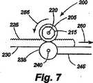
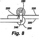
図6〜図8は、前述したような移植部材100のような環状移植部材の周囲を調整するための例示的な調整手段200を示す。調整手段200は、ラックアンドピニオン装置を含み、ラックアンドピニオン装置において、ギヤ歯車210を有する第1のカム205及び係合カプラ215は第1のアクセル220上で回転する。この例において、第1のカム205は、第1のバンド230の1つ又は複数の面のギヤラック225に係合する。第1のバンド230は、第1のカム205と、第2のバンド245に結合された第2のアクセル240上で回転する第2のカム235との間を通過する。図8に示すように、第1のアクセル220及び第2のアクセル240は、第2のバンド245の端部に形成されたブラケット250によって適当な間隔を置いた関係で維持される。 6-8 illustrate an exemplary adjustment means 200 for adjusting the circumference of an annular implant member, such as the
調整手段200は、前述したタイプの中空の環状移植部材100内に設置されることが好ましいが、第1のバンド230と第2のバンド245が同じ連続した環状構造の両端であるスタンドアロン形状の調整手段を使用することが可能である。いずれの場合においても、調整手段200を含む移植部材の長さを調整するために、6角レンチのようなツールが、第1のカム205上の係合カプラ215に係合し、図7の矢印255によって示されるように反時計回りの方向に第1のカムを回転させる。第1のカム205の回転は、歯210がラック225を駆動し、図7の矢印260によって示されるように、右に向かって第1のバンド230を移動させる。第1のバンドのこの運動は、環状移植部材の周囲を締め付ける。医師がうっかり移植部材をきつく調整しすぎると、係合カプラ215の反対方向が移植部材を緩める。 The adjustment means 200 is preferably installed in a hollow
本発明による種々の実施例において、第1のバンド230及び第2のバンド245は、分離した構造であってもよく、同じ連続構造の両端であってもよい。このような実施例において、係合カプラ215に動きが付与されたとき、第1のカム205が回転し、ギヤ歯車210をギヤラック225に係合させ、第1のバンド239を第2のバンド245に関して移動させ、移植部材の周囲を調整する。 In various embodiments according to the present invention, the
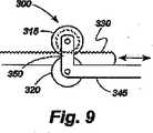
図9は、本発明による例示的な係合手段300のわずかに異なる形状を示しており、この場合、係合カプラはなく、ブラケット350が、第1のカム315と第2のカム320を接近して維持するためにカムの両側に設けられる。1つの提案される実施例において、ブラケットは、第1のバンド330を第2のバンド345に対して緊密に押し、それにより、摩擦によって固定された相対位置にバンドを保持するように緊密な公差で設計されている。他の提案される実施例において、ブラケット350は、カム315、320がカムの間に第1のバンド330を挿入するために離れることができるように弾性材料から作られ、このとき、摩擦によって固定された相対位置にバンド330、345を保持するために十分な力でカムは後方に引かれる。カム315、320の間に弾性取り付け構成を含むさらに別の提案される実施例において、第1のバンド330の下縁及び第2のバンド345の上縁は、かみ合う摩擦面又は機械的表面を有し、それによって、カム315、320は、バンドの間の相対運動を可能にするために離れ、又は固定関係でバンドを一緒にクランプするために解放されるようにすることができる。 FIG. 9 shows a slightly different shape of an exemplary engagement means 300 according to the present invention, in which there is no engagement coupler and the
図10は、本発明による移植部材の例示的な取り付け手段400を示す。取り付け手段400は、たとえば、移植部材10の取り付け手段25の代わりに使用されることができる。取り付け手段400は、内腔420と取り付け面425とを画定する壁415を含むグロメット410の形態をとる。このような取り付け手段は、内腔420を貫通する移植部材本体と共に、及び取り付け面425の上で結ばれるか又はそれを通して固定される縫合糸若しくはワイヤ等の固定装置と共に使用される。 FIG. 10 shows an exemplary attachment means 400 for an implant according to the present invention. The attachment means 400 can be used in place of the attachment means 25 of the
図11は、本発明による移植部材の取り付け手段500の別の代替的な実施例を示す。取り付け手段500は、たとえば、移植部材10の取り付け手段25の代わりに使用されることもできる。図11は、内腔520、外面525及び取り付けタブ530を画定する壁515を含む中空の管又は管部材510の形態の取り付け手段500を示す。このような取り付け手段は、内腔520を貫通する移植部材本体と共に、及び取り付けタブ530の上で結ばれるか又はそうでなければそれを通して固定される縫合糸若しくはワイヤ等の固定装置と共に使用される。このような固定装置は、取り付けタブ530内に設けられた穴535を通して配置される。代替的に、中実の取り付けタブ530が設けられてもよく、固定装置が、中実のタブを貫通していてもよい。これらの取り付け手段の変形形態は、縫合糸のない取り付けシステムに関連して使用されることができる。 FIG. 11 shows another alternative embodiment of the implant attachment means 500 according to the present invention. The attachment means 500 can be used instead of the attachment means 25 of the
図12〜図18は、本発明による皮下環状形成装置の別の実施例を示しており、この実施例において、移植部材/供給システム配列600は、ハウジング鞘部605(図12には示さず)、ハウジング鞘部605内に同軸的に摺動可能に取り付けられた作動カテーテル610と、作動カテーテル610内に同軸的に摺動可能に取り付けられたコアカテーテル615とを含む。コアカテーテルは、中央の内腔616(図13)を有する。作動カテーテル610及びコアカテーテル615は、丸い管状の構造体であるか、又は図13に示すように、作動カテーテル及びコアカテーテルのいずれか又はその双方がハウジング鞘部665又は作動カテーテル610のいずれかの内腔内で1つ又は複数の往復動スロット622、624によってそれぞれ受けられる1つ又は複数のキー付隆起部618、620をそれぞれ備えていてもよい。このようなキー付き隆起部618、620は、使用中に望ましくない回転運動による不意の変位から内側内容物の制御を維持するためにこのような制限が望ましいならば、外側部材内での内側部材の内部回転を制限する。 12-18 illustrate another embodiment of a subcutaneous annuloplasty device according to the present invention, in which the implant /
移植部材/供給システム配列600は、コアカテーテル615の前端に遠位先端625を含む。1つ又は複数の半径方向移植部材支持アーム630は、その遠位先端625に隣接してコアカテーテル615に回転可能に又は屈曲可能に取り付けられたそれらの遠位端632を有する。半径移植部材支持アーム630の近位端634は、通常はコアカテーテル615に沿って伸びているが、コアカテーテルから離れるように外側に変位することができる。 The implant /
1つ又は複数の半径支持ストラット636は、作動カテーテル610の遠位端に回転可能に又は屈曲可能に取り付けられた近位端638を有する。各半径支持ストラット636の遠位端640は、対応する半径移植部材支持アーム630の中間点に回転可能に又は屈曲可能に取り付けられている。作動カテーテル610が、コアカテーテル615に対して前進するとき、半径支持ストラット636は、半径移植部材支持アーム630を傘のフレームのように上方及び外側に押す。したがって、作動カテーテル610、コアカテーテル615、半径支持ストラット636、半径支持アーム630は組み合わされて展開傘642を形成する。 One or more radial support struts 636 have a
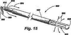
補綴移植部材645は、半径移植部材支持アーム630の近位端634に解放可能に取り付けられている。補綴移植部材645の周囲及びそこから近位方向に複数の保持針646が伸びている。さらに、1つ又は複数の半径移植部材支持アーム630は、近位端が移植部材645の近位に伸びているタッチダウン・センサ648を含む。例示的な実施例600のコアカテーテル615の中央内腔616(図13)を貫通し、遠位先端625から近位に間隔を置いて側方ポート650の外側(図12)に1つ又は複数の解放部材660があり、これは、供給システムから移植部材645を解放するように作用し、また、移植部材の展開寸法及び効果を調整するように作用する1つ又は複数の調整部材665がある。解放部材660及び調整部材665は、図14〜図16で理解できるようにコアカテーテル615の近位端を貫通しているので、これらの部材は、医師によって直接又は間接的に器具として用いられるか、操作されることができる。供給インタフェイス670(図12、図16)は、この例において、展開傘642、解放部材660及び移植部材645の相互作動によって画定される。開示した実施例において、解放部材660は、移植部材645と半径移植部材支持アーム630とにおいてレーザドリル穴を貫通し、次にコアカテーテル615の長さを貫通する連続ループ内の縫合糸、ファイバ、又はワイヤであり得る。このような実施例において、移植部材645は、患者の外側の近位端で解放部材660を切り離し、続いてコアカテーテル610を介して解放部材660の自由端を引くことによって、所望のときに供給システムから解放されることができる。 The prosthetic implant 645 is releasably attached to the proximal end 634 of the radial implant support arm 630. A plurality of retention needles 646 extend around and proximally from the prosthetic implant 645. Additionally, the one or more radial implant support arms 630 include a
図14〜図16は、移植部材/供給システム配列600の動作を示し、その動作において、補綴移植部材645の傘状の膨張がハウジング鞘部605、作動カテーテル610、及びコアカテーテル615の摺動運動によって達成される。まず、図14を参照すると、ハウジング鞘部605は、移植部材/供給システム配列600の静脈内挿入のために作動カテーテル610及びコアカテーテル615の前端をカバーするために延びている。この開始位置から、ハウジング鞘部605は、矢印662によって示される方向に後退する。図15において、ハウジング鞘部605は、作動カテーテル610の前端及び折りたたまれた展開傘642を露出するために後退している。作動カテーテル610は、この位置から、矢印664によって示される方向に前進させられる。これは、矢印666によって示される方向に展開傘を拡張させる。図16は、コアカテーテル615に対する作動カテーテル610の遠位の動きによって生じる展開傘642の拡張を示す。移植部材645が配置され、適当な寸法に調整された後、ハウジング鞘部605は、矢印668によって示される方向に前進させられ、患者から装置を引き抜くために展開傘642を折りたたみ、カバーする。 FIGS. 14-16 illustrate the operation of the implant /
図17及び図18は、移植部材/供給システム配列600の半径移植部材支持アーム630及び半径支持ストラット636を示す概略図である。図17において、半径支持ストラット636が、第1の回転可能な接続点670でその近位端638で作動カテーテル610に回転可能に取り付けられている。半径支持ストラット636はその遠位端640を、対応する半径移植部材支持アーム630の中間点で第2の回転可能な接合点672に取り付けられている。半径移植部材支持アーム630は、第3の回転可能な接合点674によってその遠位端632でコアカテーテル620に取り付けられている。図17は、閉鎖状態におけるアセンブリを示す。作動カテーテル610が、矢印676によって示されるようなコアカテーテル615上を遠位方向に前進させられるとき、矢印678によって示されるような第1の回転可能な接合部670、第2の回転可能な接合部672及び第3の回転可能な接合部674での動きによって半径支持ストラット636及び半径移植部材支持アーム630は延長される。この動きは、(図17及び図18には示さない)展開傘及び折りたたまれた移植部材を延ばす効果を有し、図12〜図16に関して前述したように係合及び移植の前に、その最も大きな半径方向の寸法を達成することを可能とする。 FIGS. 17 and 18 are schematic diagrams illustrating the radial implant support arm 630 and the radial support strut 636 of the implant /
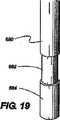
図19及び図20は、図12で前に示したタッチダウン・センサ648のさらなる詳細を示す。図19及び図20のタッチダウン・センサ648は、遠位部材680、中間部材682、及び近位部材684を含む。遠位部材680は、ばねによって取り付けられており、それにより最大の変位時に近位部材684とのシームレス接合を達成するために中間部材682上で摺動可能で、入れ子状の移動が可能である。タッチダウン・センサ648がその通常の状態にあるとき、ばねは、センサが図19に示す定位をとるように近位部材を延ばす。移植部材645(図12)が、解剖学的な開口の周囲に対して配置されるとき、センサ648の近位部材684は、図20に示すように遠位部材680に対して押し付けられる。遠位部材680及び近位部材684は、放射線不透過材料で構成されるか、その中に収められるか、そうでければ射線不透過材料でカバーされる。しかしながら、中間部材682は、このような放射線不透過材料で構成されず、放射線不透過材料でカバーもされない。したがって、遠位部材680が休止しているとき、それは、近位部材684から完全に伸張し、露出された中間部材682によって表されたギャップは、放射線試験で見ることができる。しかしながら、遠位部材680が近位部材684と最大限接近するとき、このような放射線不透過ギャップは、放射線で見ることができず、タッチダウン・センサは、「起動」されたといえる。この実施例は、遠位カテーテル部材680の延長の度合いに関してタッチダウン・センサ684の位置の放射線監視を可能にする。図示するような本発明による実施例において、移植部材を僧帽弁輪に展開するために補綴装置のための供給システムが適当な位置に配置されることを確認するために1つ又は複数のタッチダウン検出器648は使用される。この解剖学的な構造が、蛍光透視法又は標準的なX線撮影法で直接識別できないとき、このような正確な位置決めは困難であり得る。同時に、僧帽弁輪の正確な位置決め及び係合は、適当な移植部材の機能及び安全性にとって重要である。 19 and 20 show further details of the
本発明による実施例内のタッチダウン検出は、前述した例のような、伸縮式、ばね負荷式、非X線透過部材によって接合されるX線透過部材を含む複数の形態をとることができる。磁気共鳴影像法を使用する実施例において、本発明によるタッチダウン検出器は、同様の伸縮式、ばね負荷式配列の非金属部材によってはさまれた金属部材を使用することができる。他の実施例は、直接若しくは内視鏡による観察が可能な処置のための、色分けされた伸縮式、ばね負荷式の部材を有する目で確認できるシステム、又はその他の目で見える特徴を含む。本発明によるタッチダウン検出器のさらに他の実施例は、十分な圧力の瞬間的な接触が電気回路を閉成し、タッチダウン検出器の起動をオペレータに知らせるようにそれらの先端にマイクロスイッチを備えるタッチダウン検出器を含む。本発明によるさらに他のタッチダウン検出器は、移植する所望の部位に組織の独特の品質を検出することができるラーメン(Rahmen)レーザ分光法又は他の分光分析技法のための光ファイバー路を備えている。さらに、本発明によるさらに他の実施例は、所望の組織の所望の電気生理学的なインピーダンス、又は他の測定可能な品質が適当な移植のために検出されるとき、検出し且つオペレータに知らせることができる電極又は他の電気センサを含むタッチダウン検出器を含む。このような電気生理学的なタッチダウン検出器は、検出器が起動し、移植部材が取り付けのために適当な位置にあることをオペレータに知らせる視覚信号、音声信号又は他の信号を生成する電気回路を含み得る。 The touchdown detection in the embodiment according to the present invention can take a plurality of forms including an X-ray transmissive member joined by a telescopic, spring-loaded, non-X-ray transmissive member as in the above-described example. In an embodiment using magnetic resonance imaging, the touchdown detector according to the present invention can use a metal member sandwiched by non-metallic members of a similar telescopic, spring loaded arrangement. Other embodiments include eye-visible systems with color-coded telescopic, spring-loaded members, or other visible features for procedures that can be observed directly or endoscopically. Yet another embodiment of the touchdown detector according to the present invention provides microswitches at their tips so that momentary contact of sufficient pressure closes the electrical circuit and informs the operator of activation of the touchdown detector. Including a touchdown detector. Yet another touchdown detector according to the present invention comprises an optical fiber path for Rahmen laser spectroscopy or other spectroscopic techniques that can detect the unique quality of tissue at the desired site to be implanted. Yes. Furthermore, yet another embodiment according to the present invention detects and informs the operator when the desired electrophysiological impedance of the desired tissue, or other measurable quality is detected for proper implantation. A touchdown detector including electrodes or other electrical sensors capable of Such an electrophysiological touchdown detector is an electrical circuit that generates a visual, audio or other signal that informs the operator that the detector is activated and the implant is in the proper position for attachment. Can be included.
本発明によるさらに他の実施例において、血管の超音波、核磁気共鳴、仮想解剖学的位置決め装置、又は他の影像技術を含むが、これに限定されない他の心臓内撮影技術、又は心臓外影像技術を用いて、移植部材の適当な位置決めを確認し、前述したようなタッチダウン・センサについての必要性を解消する。 In yet other embodiments according to the invention, other intracardiac imaging techniques, or extracardiac images, including but not limited to vascular ultrasound, nuclear magnetic resonance, virtual anatomical positioning device, or other imaging techniques. Technology is used to confirm proper positioning of the implant and eliminate the need for touchdown sensors as described above.
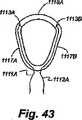
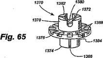
図21〜図24は、本発明の一実施例による移植部材700を示している。この実施例において、移植部材本体705は、帯状で可撓性を有する。その十分な長さを通して、移植部材本体705は、一連の保持針710を備えており、この針710は、装置の配置、保持及び取り外しを容易にする方向に向けられる。また、移植部材本体705は、調整可能な部分715を備えており、この部分715は、この例において、一連の調整停止部720を備えている。調整停止部720は、スロット、穴、戻り止め、くぼみ、隆起部、歯、隆起部材、又は使用中に移植部材700の測定される調整を可能にする他の機械的な特徴であり得る。図21〜図24に示す実施例において、調整停止部720は、ギヤ付コネクタ725と係合する。図21は、それ自体が湾曲した移植部材本体705を示す端面図であり、保持針710が外側に向かい、調整可能な部分715がギヤ付コネクタ725との係合部を貫通し、移植部材本体705内で内側に湾曲することにより閉鎖された丸い構造を形成している。図23は、例示的なギヤ付コネクタ725の詳細を示し、ここでハウジング730は移植部材本体705に接続されている。ハウジング730は、第2のギヤヘッド755とかみ合う取り付けられる第1のギヤヘッド750を有する機械的ウォーム740を含むと共に支持する。第2のギヤヘッド755は、調整ステム760に取り付けられ、この調整ステム760は、ネジ回し状の調整部材を受けるように機械加工されている。本発明による種々の実施例は、多数の形態の調整部材を必要とし得る。本例において、調整部材は、調整ステム760(図示せず)の受容スロットによって受けられるように機械加工された遠位先端を有する細かく巻かれたワイヤとして提供される。調整部材の遠位先端と調整ステム760との間の関係は、ネジ回しビット及びねじヘッドと機械的に同様であり、それによりオペレータによって調整手段に付与されるねじれは結果として、調整ステム760及び第2のギヤヘッド755を回転させ、第1のギヤヘッド750及びウォーム740の動きを可能にし、これは、ウォームが一連の調整頭部725と係合するとき、調整可能な移植部材の部分715の動きを形成する。調整可能な部分715の余分な長さは、バンドスロット735を貫通し(図23)、バンドを閉鎖した移植部材本体705の内側に同心的に移動させることができるようにする。この実施例の調整部材は、展開傘が後退し引き抜かれた後、所定の位置に保持されるように設計されることができる。調整部材の遠位先端と調整ステム760との間の接続は、簡単な摩擦接続であるか、機械的なキー/スロット形成であってもよく、又は磁気的に若しくは電気的に維持されてもよい。 21-24 show an
さらに図21に示すように、例示的な実施例は、移植部材本体705の外周に取り付けられる単一方向性の保持針710を使用する。展開時に所望の組織に接触する際、移植部材本体の回転運動が保持針710に係合するか又はそれを解放するように、保持針710は一貫して移植部本体705に対して正接方向を向いている。保持針710のこの位置決めによってオペレータが移植部材700をその軸線上に丸めることで移植部材700を「ねじ込む」ことができるようにし、したがって保持針710を隣接する組織内に係合させる。図24に示すように、保持針710はそれぞれ、周囲の組織を把持する(魚釣りフックによく似ている)端子フック775の作動により、移植部材700を反対方向に回転させることなく移植部材700を回転させることによって保持針710に係合するとき、組織を円滑に通過することのできるように端部に端子フック775をさらに備えることもできる。端子フック775はこれにより、移植部材700を周囲の組織内に配置することを確実にする。 As further shown in FIG. 21, the exemplary embodiment uses a
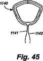
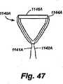
図25〜図27は、本発明によって考えられる移植部材800の別の実施例を示している。移植部材800は、バンド805(図27)を含むが、上記例の保持針は、外側織物移植部材鞘部810に関しては省略されている。織物鞘部810は、所望の位置で解剖学的な組織に縫合されるか、又はそうでなければ固定されることができる。移植部材本体800の周囲は、図23に示される帯状移植部材配列のギヤコネクタと同様にギヤコネクタ825によって調整される。さらに詳細には、バンド上の調整停止部820は、取り付けられる第1のギヤビード850によって機械的ウォーム840と係合する。第1のギヤヘッド850は、第2のギヤヘッド855とかみ合う。第2のギヤヘッド855は、調整ステム860に取り付けられ、調整ステム860は、ねじ回し状の調整ステム部材を受けるように機械加工される。 Figures 25-27 illustrate another embodiment of an
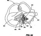
図28は、虚血性弁輪拡張症)及び僧帽弁逆流を有する患者内に移植部材645を位置決めするための移植部材/供給システム配列600の使用方法の例を示す。周囲の動脈のアクセスは、従来の静脈切開、動脈穿刺、又は標準のアクセス技術を介して得られる。動脈システムへのアクセスが得られた後、ガイドワイヤの配置が実行され、蛍光透視法、超音波、三次元超音波、磁気共鳴、又は他のリアルタイム影像技術を使用して心臓900への血管内のアクセスが得られる。ガイドワイヤ、展開装置及び移植部材は、左心室905に入ってから左心房910に入るというように逆方向に大動脈弁を貫通される。この時点において、オペレータは、ハウジング鞘部605を後退させ、したがって、折りたたまれた展開傘642及び移植部材645の鞘部をはずす。展開傘642は次に、作動カテーテルの遠位運動によって広がり、半径方向の支持アームとストラットとを完全に広げる。この時点では、タッチダウン検出器648は中実の構造には接触せず、影像システムで見ることができるそれらのX線ギャップによって完全に拡張される。展開傘が拡張すると、アセンブリ全体が僧帽弁915の領域に対して後方に引かれる。少なくとも2つのタッチダウン検出器648は、本発明による好ましい実施例において使用される。すべてのタッチダウン検出器がそれらの中間にある非不透過な中間部材の消失を示して起動されるとき、展開傘は、僧帽弁輪/動脈組織の領域の中実組織と接触していなければならず、さらに移植部材の展開と調整が進行されることができる。しかしながら、いずれかのタッチダウン・センサが起動せず、X線ギャップが存在する場合、その装置は、適切には配置されず、さらなる展開の前に再配置されなければならない。したがって、タッチダウン・センサ・システムは、本発明による供給システムによって補綴装置の展開及び調整を補助することができる。適切に配置されると、オペレータは、作動カテーテルを前述した時計方向又は反時計方向に回転させて僧帽弁輪/心房組織領域の組織内の移植部材上に保持針を係合させる。再配置が必要であれば、反対の動きによって、環状体/心房組織から保持針を離脱させ、適当な配置のためにタッチダウン検出器を再び使用して再位置決めを実行することができる。しっかりと配置されると、調整部材(複数可)は、所望の度合いの環状の低減を達成するために作動される。リアルタイムの経食道的心エコー検査、血管内心エコー検査、心臓内心エコー検査、又は僧帽弁の機能を評価するための他のモダリティを使用することにより、僧帽弁の機能に対する生理学的な治療の効果を評価してもよく、追加の調整が実行されてもよい。所望の結果が達成されると、解放部材が起動されて展開傘から移植部材を取り外す。次に、オペレータは、作動カテーテルを後退させ、ハウジング鞘部を延長させ、展開傘を収縮させ、心臓と血管系とから装置を円滑に且つ、それらを傷つけないように引き抜くために部品をカバーする。 FIG. 28 shows an example of how the implant /
所望ならば、調整部材は、カテーテル部品が引き抜かれた後、さらなる生理学的な調整のために所定位置に残されてもよい。本発明による他の実施例において、カテーテルをベースにした調整部材は、皮下の経路又は他の経路を通して続いて再び挿入されることができる。このような調整部材は、オペレータによって操向操作が可能であり、移植部材内に含まれる調整可能な機構を有する調整部材の結合が可能になるように磁気、電気、電磁気又はレーザによって案内するシステムを備えていてもよい。さらに他の実施例において、調整機構は、移植される電気機械モータ又は他のシステムによって駆動され、これらのシステムは、電気フラックス又は他の遠隔操作による皮下的又は経皮的な方法によって遠隔制御されることができる。 If desired, the adjustment member may be left in place for further physiological adjustment after the catheter part has been withdrawn. In other embodiments according to the invention, the catheter-based adjustment member can be subsequently re-inserted through the subcutaneous route or other routes. Such an adjustment member can be steered by an operator and is guided by a magnetic, electrical, electromagnetic or laser so that an adjustment member having an adjustable mechanism contained within the implant can be coupled. May be provided. In yet another embodiment, the adjustment mechanism is driven by an implanted electromechanical motor or other system, which is remotely controlled by subcutaneous or transcutaneous methods with electrical flux or other remote operation. Can.
肺動脈弁治療の場合、最初のカテーテルの最初のアクセスは、周囲の静脈又は中央の静脈を貫通することによって達成される。肺動脈弁へのアクセスはまた、中央の静脈のアクセスが右心房、三尖弁、右心室を横切り、続いて肺動脈弁に到達することによって達成されると、弁の下から達成される。 In the case of pulmonary valve treatment, initial access of the first catheter is achieved by penetrating the surrounding vein or central vein. Access to the pulmonary valve is also achieved from below the valve when central venous access is achieved by traversing the right atrium, tricuspid valve, right ventricle and subsequently reaching the pulmonary valve.
本発明によるさらに他の実施例において、左心房へのカテーテルのアクセスは、中央の血管又は周囲の血管のカニューレ挿入で達成されることができ、それによって右心房へのアクセスも達成される。標準的な心房の経中隔手法は次に、医原性心房中隔欠損症(ASD)が引き起こされることよって左心房へアクセスするために使用されることができる。このような状況において、僧帽弁は、実施形態1に説明した逆方向のアクセスとは反対に弁の上の方からアクセスされることができる。移植部材及び反転した展開傘は、前述したものと同じ治療技術により、僧帽弁輪の心房の観点において移植部材の配置に使用されることができる。医原病ASDは次に、標準の装置及び方法を使用して閉鎖されることができる。また、大動脈弁へのアクセスはまた、同様の逆方向の態様において心房のアクセスを介して大動脈弁の上の方から達成することができる。 In yet another embodiment according to the present invention, catheter access to the left atrium can be achieved by cannulation of the central or surrounding blood vessels, thereby achieving access to the right atrium. The standard atrial transseptal approach can then be used to access the left atrium by causing an iatrogenic atrial septal defect (ASD). In such a situation, the mitral valve can be accessed from the top of the valve as opposed to the reverse access described in
本発明による調整可能な移植部材及び方法の他の実施例は、食道胃逆流症(GERD)のような胃腸疾患を含む。胃と食道(GE)との接合部が、胃の内容物の食道への逆流を防止するために適切な括約筋トーヌスを欠損している状態では従来の胸焼け又は酸の逆流を生じる。これは不快なだけでなく、前ガン性病変(バレット食道)の進行又はGE接合部における食道の腺ガンを招く可能性がある経時にわたる、食道の下部への障害を生じる可能性がある。GE接合部の外科的な治療は、歴史的にニッセンのフンドプリケーションによって達成されてきており、手術方法は一般に良好な結果を有する。しかしながら、ニッセンの処置は、通常、麻酔及び入院を必要とする。本発明による装置及び方法を使用することによって、調整可能な移植部材は、入院の必要性を解消し、医院又は胃腸科専門医の診療室で実行される。ここで図29及び図30を参照すると、移植部材645を有する傘展開装置600は、内視鏡1000の案内のもとに患者の口、食道1005を通り胃1010に入り、ここで展開装置600は、色分けされるか又はそうでなければ目視可能なギャップを有する移植部材645及びタッチダウン検出器648の拡張によって開かれる。次にタッチダウン検出器は、直接的な内視鏡の制御のもと、すべてのタッチダウン検出器648が視覚的に起動されるまで、胃と食道の接合部1015の周りで胃に係合される。移植部材は次に、胃壁1020に取り付けられ、移植部材645及び調整部材を残して、傘642は解放され引き抜かれる。次に、移植部材は、所望の効果が達成されるまで、すなわち、患者の症状、食道のpH監視、影像による研究、又は他の診断手段のいずれかによって酸の逆流が最小限となるまで調整される。患者に、ガスの膨張の症状、治療が困難であり、患者がげっぷをすることができない胃と食道との接合部の治療の一般的な合併症があるときには、移植部材は、さらに所望の効果が得られるまで緩められることができる。 Other examples of adjustable implants and methods according to the present invention include gastrointestinal diseases such as esophageal reflux disease (GERD). Conventional heartburn or acid reflux occurs when the junction between the stomach and esophagus (GE) lacks the proper sphincter tonus to prevent reflux of the stomach contents to the esophagus. This is not only uncomfortable, but can also cause damage to the lower part of the esophagus over time that can lead to progression of precancerous lesions (Barrett's esophagus) or adenocarcinoma of the esophagus at the GE junction. Surgical treatment of GE junctions has historically been achieved by Nissen funding, and surgical methods generally have good results. However, Nissen treatment usually requires anesthesia and hospitalization. By using the apparatus and method according to the present invention, the adjustable implant eliminates the need for hospitalization and is performed in the clinic or gastroenterologist's office. Referring now to FIGS. 29 and 30, an
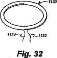
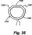
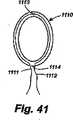
本発明によって考えられる種々の実施例において、移植部材本体は、直線、曲線、円形、卵型、多角形、又はそれらのいくつかの組み合わせであり得る。本発明によって考えられる種々の実施例において、移植部材は、身体内のオリフィス又は内腔の均一又は非均一な調整を提供することができる。さらに、移植部材本体は、自然の受容的な解剖学的な部位を完全に包囲することができるか、又は自然の受容的な解剖学的な部位の一部のみを包囲する、妨げられた形態で供給されることができる。本発明のさらに他の実施例において、移植部材本体は、中実の構造であってもよく、さらに他の実施例では移植部材本体は、管状又は中空の構成を形成し得る。本発明の1つの実施例において、本体はさらに、外側部材、内側部材及び選択的な取り付け部材を有する構造であってもよい。このような実施例において、移植部材本体の外側部材は、移植部材のカバーとして機能してもよく、自然の受容的な解剖学的な部位への組織の内部成長及び生物学的な一体化を容易にし且つ促進するように設計される。このような実施例における外側部材は、Dacron、PTFE、可鍛金属の生物学的に互換性のある材料、又は他の生物学的に互換性のある材料、或いは成型され、織られるか、又は不織構造のそれらの生物学的に互換性のある材料の組み合わせから製造され得る。このような実施例において、外側部材は内側部材を包囲するようにも作用する。この実施例において、内側部材は、調整機構によって作動されるとき、一定の方法で外側部材の形状及び/又は寸法を変更することができる調整手段を提供する。 In various embodiments contemplated by the present invention, the implant member body can be straight, curved, circular, oval, polygonal, or some combination thereof. In various embodiments contemplated by the present invention, the implant can provide uniform or non-uniform adjustment of the orifice or lumen within the body. Further, the implant member body can completely surround the natural receptive anatomical site, or can be a hindered form that surrounds only a portion of the natural receptive anatomical site. Can be supplied at. In still other embodiments of the invention, the implant member body may be a solid structure, and in still other embodiments the implant member body may form a tubular or hollow configuration. In one embodiment of the invention, the body may further be a structure having an outer member, an inner member, and an optional attachment member. In such an embodiment, the outer member of the implant member body may serve as a cover for the implant member, allowing tissue ingrowth and biological integration to natural receptive anatomical sites. Designed to facilitate and facilitate. The outer member in such an embodiment may be Dacron, PTFE, malleable metal biologically compatible material, or other biologically compatible material, or molded, woven, or It can be manufactured from a combination of those biologically compatible materials in a non-woven structure. In such an embodiment, the outer member also acts to surround the inner member. In this embodiment, the inner member provides an adjustment means that can change the shape and / or dimensions of the outer member in a certain manner when actuated by an adjustment mechanism.
本発明による代替的な実施例において、調整手段は、外側部材の外側に配置されるか、又はその内側に組み込まれてもよい。本発明によって考えられるさらに他の代替的な実施例において、移植部材本体は、上記調整手段をカバーする別個の外側部材のない調製手段から成ることができる。 In an alternative embodiment according to the invention, the adjusting means may be arranged outside or incorporated inside the outer member. In yet another alternative embodiment contemplated by the present invention, the implant member body may consist of a preparation means without a separate outer member covering the adjustment means.
本発明による種々の実施例において、調整手段は、ねじ又はねじのない機構を含んでもよく、ねじ又はウォームねじ、摩擦機構、摩擦移動止め機構、歯付き機構、ラチェット機構、ラックアンドピニオン機構、又はそのような他の装置の作用によって係合され得る機構を含み、適当な寸法が決定された後、所望の寸法及び所望の位置の慎重な調整及び保持を可能にする。 In various embodiments according to the present invention, the adjustment means may include a screw or screwless mechanism, such as a screw or worm screw, a friction mechanism, a friction detent mechanism, a toothed mechanism, a ratchet mechanism, a rack and pinion mechanism, or It includes mechanisms that can be engaged by the action of such other devices, allowing for careful adjustment and retention of the desired dimensions and desired position after the appropriate dimensions have been determined.
本発明によるさらに他の機構において、調整手段は、スネア、パースストリング状の機構を含んでもよい、その場合、縫合糸、バンド、ワイヤ、又は他の繊維構造、編み込まれるか又は編み込まれていない、モノフィラメント又はマルチフィラメントは、外科医又は他のオペレータによって上記ワイヤ又は繊維構造に付与される張力又は動きの変化時に自然の解剖学的な受容部位への移植部材装置の解剖学的及び/又は生物学的な効果を与えることができる。このような調整手段は、種々の実施例において円形又は非円形の構造として提供され得る。張力又は動きの変化は、移植部材の寸法及び/又は形状を変化させることができる。 In yet another mechanism according to the present invention, the adjustment means may include a snare, parse string mechanism, in which case a suture, band, wire or other fibrous structure, knitted or not knitted, Monofilaments or multifilaments are anatomical and / or biological of the implant device to a natural anatomical receiving site upon changes in tension or movement applied to the wire or fiber structure by a surgeon or other operator. Effects can be given. Such adjustment means may be provided as a circular or non-circular structure in various embodiments. Changes in tension or movement can change the size and / or shape of the implant.
本発明による種々の実施例において、調整手段は、金属材料、プラスティック材料、合成材料、天然材料、生物学的材料又は他の生物学的に互換性のある材料又はそれらの組み合わせであってもよい。このような調整手段は、さらに、押出し成形、又は他の成型技法、機械加工、又は編み込みによって製造されることができる。さらに本発明の種々の実施例において、調整手段は、平滑であってもよく、スロット、ビード、隆起部又は任意の他の平滑面若しくは織物面を含んでいてもよい。 In various embodiments according to the present invention, the adjustment means may be a metallic material, plastic material, synthetic material, natural material, biological material or other biologically compatible material or combinations thereof. . Such adjustment means can further be manufactured by extrusion or other molding techniques, machining, or braiding. Further, in various embodiments of the present invention, the adjustment means may be smooth and may include slots, beads, ridges or any other smooth or woven surface.
本発明の種々の実施例において、移植部材本体は、自然の受容部位への移植部材の取り付けを容易にするために、グロメット若しくは開口若しくは他の取り付け部材のような1つ又は複数の取り付け部材を備えていてもよい。代替的な実施例において、移植部材本体は、機械的組織接合システムに取り付けるか又は組み込むことができる。これにより、自然の受容部位において移植部材を固定する縫合糸のない機械的な手段を可能にする。さらに他の代替的な実施例において、縫合糸又は他の取り付け手段は、自然の受容部位に移植部材本体を固定するために、移植部材本体の周り又はそれを通して固定されることができる。本発明のさらに他の実施例において、移植部材本体を自然の受容部位に固定する機械的な手段は、フィブリン、又は他の生物学的に互換性のある組織接着剤(gives)又は同様の接着剤の使用によって補強されるか、代替され得る。 In various embodiments of the present invention, the implant member body includes one or more attachment members, such as grommets or openings or other attachment members, to facilitate attachment of the implant member to a natural receiving site. You may have. In an alternative embodiment, the implant member body can be attached to or incorporated into a mechanical tissue joining system. This allows a mechanical means without sutures to secure the implant at the natural receiving site. In still other alternative embodiments, sutures or other attachment means can be secured around or through the implant member body to secure the implant member body to the natural receiving site. In yet another embodiment of the present invention, the mechanical means of securing the implant body to the natural receiving site is fibrin or other biologically compatible tissue glue or similar adhesion. It can be reinforced or replaced by the use of agents.
本発明による他の種々の実施例において、調整可能な移植部材は、病気の進行が周囲又は他の寸法を狭くするか、又は制限する傾向にあるオリフィス、小孔、内腔又は交差連絡のこれらの周囲又は他の寸法を調整可能に拡大するか、維持するために使用することができる。 In various other embodiments according to the present invention, adjustable implants are used for orifices, stomas, lumens or cross-communications where disease progression tends to narrow or limit surrounding or other dimensions. Can be used to adjustably expand or maintain the perimeter or other dimensions of the.
本発明による種々の実施例において、調整機構は、調整手段と相互作用するように提供され、調整手段の寸法及び/又は位置における所望の変更を達成することができる。このような調整機構は、1つ又は複数のねじ、ウォームねじ配列ローラ、ギヤ、摩擦停止部、摩擦移動止めシステム、ラチェット、ラックアンドピニオン機構、マイクロ電子機械システム、他の機械的若しくは電子機械的装置又はそれらのいくつかの組み合わせを含んでいてもよい。 In various embodiments according to the present invention, an adjustment mechanism is provided to interact with the adjustment means to achieve a desired change in the size and / or position of the adjustment means. Such adjustment mechanisms may include one or more screws, worm screw array rollers, gears, friction stops, friction detent systems, ratchets, rack and pinion mechanisms, microelectromechanical systems, other mechanical or electromechanical It may include a device or some combination thereof.
本発明によって考えられるようないくつかの実施例において、調整ツールは、調整機構に取り外し可能に又は永久的に取り付けられ、調整機構に、さらには調整手段に動きを与え自然の受容部位における移植部材の解剖学的な効果を増減するために配置されることができる。 In some embodiments, such as contemplated by the present invention, the adjustment tool is removably or permanently attached to the adjustment mechanism and provides movement to the adjustment mechanism, and further to the adjustment means, in the natural receiving site. Can be arranged to increase or decrease the anatomical effects of.
本発明による他の実施例において、関連する電子制御回路を有する1つ又は複数のマイクロ電子機械モータシステムを有するマイクロモータ配列は、調整手段として提供されてもよく、電磁波による信号搬送を通して遠隔制御によって作動されるか、又は上記マイクロモータ配列に永久的に若しくは取り外し可能に取り付けられ得る電気導線による直接的な回路によって作動されることができる。 In another embodiment according to the present invention, a micromotor arrangement having one or more microelectromechanical motor systems with associated electronic control circuitry may be provided as a conditioning means, by remote control through signal transport by electromagnetic waves. It can be actuated or actuated by a direct circuit with electrical leads that can be permanently or removably attached to the micromotor arrangement.
本発明による種々のさらに他の実施例において、調整機構は、自然の受容部位及びそれが属する身体的な器官への最適な所望の解剖学的及び/又は生物学的な効果の達成時に、選択的な位置において調整手段の位置を維持するために配置された固定機構を備えていてもよい。他の実施例において、使用される調整手段の性質によっては特別な固定機構は必要なくてもよい。 In various further embodiments according to the present invention, the adjustment mechanism is selected upon achievement of an optimal desired anatomical and / or biological effect on the natural receiving site and the physical organ to which it belongs. There may be provided a fixing mechanism arranged to maintain the position of the adjusting means at a general position. In other embodiments, no special locking mechanism may be necessary depending on the nature of the adjustment means used.
本発明によるさらに他の実施例によれば、調整手段及び/又は外側部材の構造は、紫外線のような選択された波長の電磁波への露出時に硬化することができる柔軟な合成材料であってもよい。このような実施例において、所望の電磁波に露出することは、外科医による移植部材へのこのような放射の外部からの供給によって、又は上記外側部材内に配置され、適当な外部放射源に接続された光ファイバ搬送体を使用して、外側の移植部材内へのそのような放射の内側供給によって達成され得る。このような光ファイバ搬送体は、適当な放射露出及び上記調整手段の硬化の後に、外側の移植部材から全部又は部分的に除去するように配置されることができる。 According to yet another embodiment according to the invention, the structure of the adjusting means and / or the outer member may be a flexible synthetic material that can be cured upon exposure to an electromagnetic wave of a selected wavelength, such as ultraviolet light. Good. In such embodiments, exposure to the desired electromagnetic wave may be provided by an external supply of such radiation to the implant member by the surgeon or disposed within the outer member and connected to a suitable external radiation source. Using an optical fiber carrier, this can be achieved by an inner supply of such radiation into the outer implant. Such a fiber optic carrier can be arranged for complete or partial removal from the outer implant after appropriate radiation exposure and curing of the conditioning means.
本発明はまた、哺乳類の体内の血液、他の体液、栄養分、半固体、固体、又は老廃物のための通路を形成する組織の解剖学的な構造及び/又は生理的な効果を選択的に変えるために、調整可能な移植部材装置を使用する方法を提供する。調整可能な移植部材のこのような使用のための種々の実施例は、制限はされないが、外科的切開による自然の受容部位での上記調整可能な移植部材の外科的切開による配置、蛍光透視法、超音波、磁気共鳴画像法、又は他の影像技術を使用する上記移植部材の経皮又は血管経由での観察下での配置、冠動脈洞、又は食道壁のような組織構造壁を通る上記移植部材の配置、又は、上述した技法のいくつかの組み合わせを使用する方法を含む。本発明によって考えられる種々の実施例において、調整可能な移植部材は、ビーティング又は非ビーティング心臓外科手術処置又は胃腸内の内視鏡的又は経皮的な手術の際に心房を経て、心室を経て、動脈を経て、静脈(すなわち、肺静脈を介して)又は他の経路によって自然の受容解剖学的部位の所定の位置に配置されるか、固定され得る。 The present invention also selectively selects the anatomical structure and / or physiological effects of tissue forming a passage for blood, other body fluids, nutrients, semi-solids, solids, or waste products in a mammalian body. To change, a method of using an adjustable implant device is provided. Various embodiments for such use of adjustable implants include, but are not limited to, surgical incision placement of the adjustable implant in a natural receiving site by surgical incision, fluoroscopy Placement of the graft member under percutaneous or vascular observation using ultrasound, magnetic resonance imaging, or other imaging techniques, the graft through a tissue structure wall such as the coronary sinus or esophageal wall Including placement of members, or methods using some combination of the techniques described above. In various embodiments contemplated by the present invention, the adjustable implant may be passed through the atrium and ventricle during a beating or non-beating cardiac surgical procedure or endoscopic or percutaneous surgery in the gastrointestinal tract. Through the artery, via veins (ie, via the pulmonary veins), or other route, can be placed or fixed in place in the natural receiving anatomy.
さらに、調整可能な移植部材装置の使用の代替的な方法は、年少の患者の自然な受容部位の成長を許容するために必要な上記移植部材装置を受ける解剖学的な構造の寸法又は受容患者の生理学的なニーズの他の変化の移植後の定期的な調整を提供し得る。 Furthermore, an alternative method of use of the adjustable implant device is the size of the anatomical structure that receives the implant device required to allow growth of the natural receiving site of the young patient or the receiving patient. Regular adjustments after transplantation of other changes in the physiological needs of the patient may be provided.
調整可能な移植部材の調整及び本明細書に開示したようなそれらの使用のための方法は、所望の効果を達成するために必要とされる調整の性質の評価を提供するために、、外科医又はオペレータによる診断ツールの使用を考慮している。このような診断ツールは、制限はされないが、経食道心エコー検査、心エコー検査、超音波診断、血管内超音波検査、磁気共鳴と統合された目視による解剖学的ポジショニングシステム、CTスキャン又は他の影像技法、内視鏡、縦隔鏡検査法、腹腔鏡検査、胸腔鏡検査、X線撮影法、蛍光透視法、磁気共鳴画像法、CTスキャン画像法、血管内流れセンサ、熱センサ又は影像、遠隔化学分析又はスペクトル分析、又は他の影像法、量的又は質的な分析システムを含む。 Methods for adjustment of adjustable implants and their use as disclosed herein provide for the surgeon to provide an assessment of the nature of the adjustment required to achieve the desired effect. Or the use of diagnostic tools by the operator is considered. Such diagnostic tools include, but are not limited to, transesophageal echocardiography, echocardiography, ultrasound diagnosis, intravascular ultrasound, visual anatomical positioning system integrated with magnetic resonance, CT scan or other Imaging techniques, endoscope, mediastinoscopy, laparoscopy, thoracoscopy, radiography, fluoroscopy, magnetic resonance imaging, CT scan imaging, intravascular flow sensor, thermal sensor or image Remote chemical analysis or spectral analysis, or other imaging, quantitative or qualitative analysis systems.
1つの態様において、本発明の移植部材/供給システムは、折りたたみ可能、圧縮可能、又は膨張可能な移植部材及び補綴移植部材のような供給インタフェイスを含む。この供給インタフェイスは、折りたたまれるか、圧縮されるか、又は膨張していない状態で所望な解剖学的な受容部位に補綴移植部材を供給し、所望の解剖学的な受容部位でユーザがこのような補綴移植部材の制御された伸張又は膨張及び物理的な取り付けすることを可能にすることができる。このようなシステムは、供給システム及び補綴移植部材が、トロカール、鞘部を通して、セルジンガー法、針によって皮下的に、又は自然の体のオリフィス、身体内の空所、若しくは領域を内視鏡によって、所望の解剖学的な受容部位に外科医又はオペレータによって操作されて導入される。ここで、供給システム及び補綴移植部材は、展開するために操作可能に拡張され得る。所望のときは、本発明の移植部材/供給システムはまた、それが所望の解剖学的な受容部位に取り付けられると、ユーザが、補綴移植部材の寸法又は形状をさらに調整することができる。本発明による供給システムは次に、補綴移植部材を有するインタフェイスから分離し、オペレータによって解剖学的部位から取り外すことができる。供給システム及び補綴移植部材は、哺乳類である患者内の意図された自然の解剖学的受容部位の解剖学的なニーズによって決定された形状及び寸法で提供され得る。このような自然の解剖学的受容部位は、心臓弁、胃と食道との接合部付近の食道、肛門、又はその部位の寸法及び形状を変化することができ、手術の後、所望の寸法及び形状を維持することができる移植部材によって軽減されることができる機能障害を形成している、哺乳類の身体内の他の解剖学的部位であり得る。 In one aspect, the implant / delivery system of the present invention includes delivery interfaces such as collapsible, compressible, or inflatable implants and prosthetic implants. The delivery interface delivers the prosthetic implant to the desired anatomical receiving site in a collapsed, compressed or unexpanded state, at which the user can Such a prosthetic implant can be controlled to stretch or expand and physically attach. Such a system is such that the delivery system and prosthetic implant are trocar, through the sheath, under the Seldinger technique, subcutaneously with a needle, or with a natural body orifice, body cavity, or region by endoscope. , Manipulated and introduced by a surgeon or operator into the desired anatomical receiving site. Here, the delivery system and the prosthetic implant can be operably expanded for deployment. When desired, the implant / delivery system of the present invention can also allow the user to further adjust the size or shape of the prosthetic implant when it is attached to the desired anatomical receiving site. The delivery system according to the present invention can then be separated from the interface with the prosthetic implant and removed from the anatomical site by the operator. The delivery system and prosthetic implant can be provided in a shape and size determined by the anatomical needs of the intended natural anatomical receiving site in a mammalian patient. Such natural anatomical receptive sites can change the size and shape of the heart valve, the esophagus near the junction of the stomach and esophagus, the anus, or the site, and after surgery the desired size and It may be other anatomical sites in the mammalian body that form a dysfunction that can be alleviated by an implant that can maintain shape.
本発明によって考えられる種々の実施例において、供給システムは、カテーテル、ワイヤ、フィラメント、ロッド、管、内視鏡、又は、血管、オリフィス、又は組織内腔のような解剖学的な通路を通して、又は腹腔を通して、又は胸部を通して切開部、穿刺、トロカールにより、所望の解剖学的受容部位に到達することができる他の機構であり得る。本発明による種々の実施例において、供給システムは、オペレータによって操向可能である。さらに、供給システムは、所望の解剖学的受容部位に補綴移植部材を保持し、搬送する供給インタフェイスを有する。このような供給インタフェイスは操作可能に、膨張、再形成、又は所望の解剖学的な受容部位でこのような補綴移植部材の独立した膨張又は拡大を可能にすることができる。さらに、このような供給インタフェイスは、上記移植部材がそれ自身所望の解剖学的受容部位に取り付けられたとき、補綴移植部材の膨張又は拡大した寸法、形状、又は生理学的効果を調整するために操作可能な手段を提供することがきる。本発明による種々の実施例において、このような調整は、移植部材が配置される処置の間、又はその後の時間に実行され得る。特定の適用例の特定の解剖学的なニーズに応じて、供給インタフェイス及び関連する補綴移植部材は、直線、湾曲している形状、円形、螺旋形状、管状、卵形、多角形、又はそれらのいくつかの組み合わせであってもよい。本発明のさらに他の実施例において、補綴移植部材は、中実構造であってもよく、他の実施例において、補綴移植部材は、管状、複合体、又は他の中空の構造を形成し得る。本発明の1つの実施例において、補綴移植部材は、さらに、外側部材、内側部材、及び選択的な取り付け部材を有する構造であり得る。このような実施例において、補綴移植部材の外側部材は、移植部材のカバーとして作用し、自然の解剖学的受容部位への組織の内部成長及び生物学的な一体化を容易にし促進するように設計される。このような実施例における外側部材は、Dacron、PTFE、可鍛金属等の生物学的に互換性のある材料、他の生物学的に互換性のある材料、或いは成型され、織られるか、又は不織構造のそれらの生物学的に互換性のある材料の組み合わせ等から製造され得る。このような実施例の外側部材は内側部材を包囲するようにも作用する。この実施例において、内側部材は、調整機構によって作動されるとき、一定の方法で外側部材の形状及び/又は寸法を変更することができる調整手段を提供する。 In various embodiments contemplated by the present invention, the delivery system may be through a catheter, wire, filament, rod, tube, endoscope, or anatomical passage such as a blood vessel, orifice, or tissue lumen, or There may be other mechanisms that can reach the desired anatomical receiving site through the abdominal cavity or through the chest by incision, puncture, trocar. In various embodiments according to the present invention, the delivery system can be steered by an operator. In addition, the delivery system has a delivery interface that holds and conveys the prosthetic implant at the desired anatomical receiving site. Such a delivery interface can be operatively allowed to expand, reshape, or independently expand or expand such a prosthetic implant at a desired anatomical receiving site. In addition, such a delivery interface may be used to adjust the expanded or expanded size, shape, or physiological effect of the prosthetic implant when the implant is attached to the desired anatomical receiving site. An operable means can be provided. In various embodiments in accordance with the present invention, such adjustments can be performed during or after the procedure in which the implant is placed. Depending on the specific anatomical needs of a particular application, the delivery interface and associated prosthetic implant can be straight, curved, circular, helical, tubular, oval, polygonal, or Some combinations of these may be used. In still other embodiments of the invention, the prosthetic implant may be a solid structure, and in other embodiments, the prosthetic implant may form a tubular, composite, or other hollow structure. . In one embodiment of the present invention, the prosthetic implant may further be a structure having an outer member, an inner member, and an optional attachment member. In such an embodiment, the outer member of the prosthetic implant acts as a cover for the implant to facilitate and facilitate tissue ingrowth and biological integration into the natural anatomical receiving site. Designed. The outer member in such an embodiment may be a biologically compatible material such as Dacron, PTFE, malleable metal, other biologically compatible material, or molded, woven, or It can be manufactured from a combination of these biologically compatible materials in a non-woven structure. The outer member of such an embodiment also acts to surround the inner member. In this embodiment, the inner member provides an adjustment means that can change the shape and / or dimensions of the outer member in a certain manner when actuated by an adjustment mechanism.
本発明によるいくつかの実施例によれば、調整可能な内側部材又は外側部材の少なくともいくつかの部分は、このような変形が肛門失禁、又は膣脱の治療のような機能的に価値のある場合において弁、括約筋、オリフィス、又は内腔に可変の人工の筋肉トーヌスの要素を与えるために弾性的である。 According to some embodiments according to the present invention, at least some portions of the adjustable inner member or outer member are functionally valuable such a treatment such as treatment of anal incontinence or vaginal prolapse In some cases, it is elastic to provide a variable artificial muscle tonus element to the valve, sphincter, orifice, or lumen.
本発明による種々の実施例において、供給インタフェイスは、補綴移植部材がオペレータによって配置されると、補綴移植部材の元の部位での調整中に自然の解剖学的な受容部位に補綴移植部材を保持し途中を搬送をするための取り付け手段を有する。このような取り付け手段は、補綴移植部材の所望の配置及び調整が達成されると補綴移植部材の供給インタフェイスからの離脱を可能にするために操作可能に反転されることができる。 In various embodiments in accordance with the present invention, the delivery interface allows the prosthetic implant to be placed on a natural anatomical receiving site during adjustment at the original site of the prosthetic implant when the prosthetic implant is positioned by the operator. It has attachment means for holding and transporting the middle. Such attachment means can be operably inverted to allow removal of the prosthetic implant from the delivery interface once the desired placement and adjustment of the prosthetic implant is achieved.
図31〜図39は、弛緩状態のリングの種々の実施例を示す。図31は、下側部分から引き紐1111、1112が延びている円形リング1110を示す。図32は、引き紐1121、1122を有する楕円形リング130を示す。図33は、六角形リング1130を示す。図34は、直線状の脚1146によって両端が接続されている部分円1145の形状のリング1140を示す。図35は、弧状部分1154と、弧の両端を接続する3つの直線状の脚部分1155〜1157とを備えるリング1150を示す。図36は、一方の側に凸状部分1164、他方の側に凹状部分1166を有する曲線形リング1160を示す。図37は、両側1174、1176が凹状である曲線形リング1170を示す。図38は、概ね円形の形状であり上端に開口1184を有するリング1180を示す。図39は、弧状部分1194と、間に開口1197を残して互いに向かって延びている直線状の脚1195、1196とを備えるリングを示す。 31-39 show various embodiments of the ring in the relaxed state. FIG. 31 shows a
図40及び図41は、引き紐1111、1112を示すために切断されたリング1110を示す。引き紐1111、1112は、引き紐が出る場所1114とは反対側の場所1113において繋がれる。図41に示すように、引き紐が引っ張られると、リング10の全体が小さくなるように調整される。 40 and 41 show the
(場合によっては、引き紐1111、1112は、繋がれるのではなくリング1110内で自由に摺動可能であってもよく、この場合も主に同じ効果がある)。 (In some cases, the
図40及び図41の全体的に調整可能なリング1110とは対照的に、図42及び図43のリング1110Aは、部分的にしか調節可能ではない。引き紐1111A、1112Aの端は互いに合わさるのではなくリング1110Aに沿った場所1113A、1113Bに繋がれる。引き紐111A、1112Aが引っ張られると、引き紐が通っている部分1117A、1117Bが最も調整される部分となる。反対に、引き紐が全く通っていない部分1118Aは、比較的小さくしか調整されない。 In contrast to the generally
図44〜図47は、リングの調整機能に対する内部補強材の効果を示す。図1144及び図1145において、リング1140は内部補強材を有さない。その結果、引き紐1141、1142が引っ張られると、リング1140の全体が調整される。反対に、図46及び図47のリング1140Aは、リングの直線状の脚1146Aを通って延びる補強部材1144Aを有する。開示した実施例において、補強部材1144Aは中空の管である。しかしながら、補強部材1144Aが、適当な断面の中実ロッドを含む他の構成をとってもよいことが認識されるであろう。また、開示した実施例において、引き紐1141A、1142Aは、補強部材1144Aの端に繋がれている。しかしながら、引き紐が管を通って延びて、管の内部の共通の場所で繋がれるか、又は管内で自由に摺動可能であってもよいことが理解されるであろう。代替例では、引き紐は、補強部材1144Aと並んで延びて、補強部材に沿った共通の場所で繋がれるか、又は補強部材と並んで自由に摺動可能であってもよい。 44-47 show the effect of the internal reinforcement on the ring adjustment function. In FIGS. 1144 and 1145, the
図48〜図51は、引き紐が引っ張られるとリングに所定の構成をとらせるように引き紐と操作可能に連動する内部整形部材の使用を示す。最初に図48及び図49を参照すると、概ね円形のリング1200内に、複数の楔形の整形部材1201が配置されている。左側の引き紐1202は、最も右側の整形部材1201Aに接続され、右側の引き紐1203は、最も左側の整形部材1201Bに接続される。引き紐1202、1203が引っ張られると、最も右側の整形部材1201A及び最も左側の整形部材1201Bが互いに引き寄せられる。最も外側の整形部材のこの移動が、各整形部材1201の楔表面を隣接する整形部材の楔表面に到達させて、整形部材群に図49に示す凹状構成をとらせる。 48-51 illustrate the use of an internal shaping member that is operatively associated with the drawstring to cause the ring to assume a predetermined configuration when the drawstring is pulled. 48 and 49, a plurality of wedge-shaped
図48及び図49の実施例の整形部材1201は、引き紐が緊縛されると凹状構成をとるように構成されているが、整形部材の構成は、その群が凸状構成、直線、凸状部分及び凹状部分を有する蛇行構成、又は任意の所望の外形形状を形成するように設計してもよいことが認識されるであろう。 The shaping
次に図50及び図51を参照すると、概ね円形のリング1210は、楔形整形部材1211の2つの群1212、1213を有する。リング1210は、4本の引き紐を備え、楔形整形部材1211の2つの群1212、1213それぞれに一対の引き紐が関連付けられる。第1の引き紐1214は、リング1210に沿って時計回りの方向に延び、整形部材1211の第1の群1212の最も上の部材1211Aに接続される。第2の引き紐1215は、リング1210に沿って反時計回りの方向に延び、整形部材1211の第1の群1212の最も下の部材1211Bに接続される。同様に、第3の引き紐1216は、リング1210に沿って時計回りの方向に延び、整形部材1211の第2の群1213の最も下の部材1211Cに接続され、第4の引き紐1217は、リングに沿って反時計回りの方向に延び、整形部材の第2の群1213の最も上の部材1211Dに接続される。 Referring now to FIGS. 50 and 51, the generally
4本の引き紐1214〜1217が緊縛されると、整形部材1211の第1の群1212が寄せ集められ、整形部材の第2の群1213が寄せ集められる。部材1211の2つの群1212、1213は、所定の外形形状をとって、リング1210に図51に示す卵形構成をとらせる。 When the four drawstrings 1214-1217 are tied together, the
図50及び図51の実施例の整形部材の2つの群は、同一の外形形状を形成しているが、各群が異なる形状を形成するように整形部材の構成を設計してもよいことが理解されるであろう。同様に、図50及び図51の実施例の整形部材の2つの群は、凸状の外形形状を形成しているが、整形部材の構成は、凹状構成、直線、若しくは凸状部分及び凹状部分を有する蛇行構成、又はこれら及び他の形状の任意の組み合わせをとるように構成してもよいことが認識されるであろう。 The two groups of shaping members in the embodiment of FIGS. 50 and 51 have the same outer shape, but the configuration of the shaping members may be designed so that each group forms a different shape. Will be understood. Similarly, the two groups of shaping members of the embodiment of FIGS. 50 and 51 form a convex outer shape, but the shaping member may be a concave configuration, a straight line, or a convex portion and a concave portion. It will be appreciated that it may be configured to take a serpentine configuration having any of these, or any combination of these and other shapes.
図31〜図51の装置は全て、弛緩状態にあるときは基本的に単一平面上にあり、引き紐が引っ張られているときもさらに基本的に単一平面上にある。図52〜図55は、内部整形部材がリングをより3次元的な形状に調整するように構成される実施例を示す。 All of the devices of FIGS. 31-51 are essentially on a single plane when in a relaxed state, and even more fundamentally on a single plane when the drawstring is being pulled. 52-55 show an embodiment in which the internal shaping member is configured to adjust the ring to a more three-dimensional shape.
最初に図52を見ると、リング1220が、2つの群1222、1223に形成された複数の整形部材1221を備える。リングが平坦な状態では、整形部材の幅は下部よりも上部の方が狭い。したがって、引き紐1224〜1227が緊縛されると、リングは上向きに曲がって図53に示す鞍形構成になる。 52, the
図54及び図55は、さまざまな異なる構成の整形部材1231を備えるリング1230の実施例を示す。図示を明確にするために、図54及び図55では整形部材1231のうちのいくつかのみを示している。整形部材1231は、下部よりも上部の方が幅狭の整形部材の群1232と、上部よりも下部の方が幅狭の整形部材の群1233とが交互になって配置される。上述の原理を利用すると、いくつかの整形部材を下部よりも上部の方が幅狭であるようにし、いくつかの整形部材を上部よりも下部の方が幅狭であるようにすることによって、複雑な3次元構成を達成できることが分かるであろう。 54 and 55 show an embodiment of a
上記の例から、リングは、曲線状(図31、図32、及び図36〜図38)、直線状(図33)、又は直線部分及び曲線部分の組み合わせ(図34、図35、及び図39)であり得ることが明らかであろう。リングは、完全に閉じていても(図31〜図37)部分的に閉じていても(図38及び図39)よい。リングは、全体的に調整可能(図40、図41、図44、及び図45)であっても部分的に調整可能(図42、図43、図46、及び図47)であってもよい。リングは、補強されていなくても(図31〜図45)補強されていても(図46及び図47)よい。リングは、2次元(図48〜図51)又は3次元(図52〜図55)の特定の外形構成をとる整形部材を含むことができる。 From the above example, the ring can be curved (FIGS. 31, 32, and 36-38), linear (FIG. 33), or a combination of linear and curved portions (FIGS. 34, 35, and 39). It will be clear that this is possible. The ring may be fully closed (FIGS. 31-37) or partially closed (FIGS. 38 and 39). The ring may be totally adjustable (FIGS. 40, 41, 44, and 45) or partially adjustable (FIGS. 42, 43, 46, and 47). . The ring may be unreinforced (FIGS. 31-45) or reinforced (FIGS. 46 and 47). The ring can include a shaping member that takes a specific external configuration in two dimensions (FIGS. 48-51) or three dimensions (FIGS. 52-55).
図31〜図55の実施例は全て、移植部材の周囲を調整する手段として引き紐を用いる。図56〜図70の実施例では、調整可能な移植部材がウィンチを用いてリングの周囲を伸縮させるという異なる手法をとる。最初に図56を見ると、僧帽弁輪の構成を調整するためのシステム1300が、調整可能なリング1310、駆動ユニット1312、及びウィンチ1314(図56では駆動ユニット1312の下端内にほぼ隠れている)を含む。次に、これらの部品それぞれをより詳細に説明する。 All of the embodiments of FIGS. 31-55 use a drawstring as a means of adjusting the periphery of the implant. The embodiment of FIGS. 56-70 takes a different approach in which the adjustable implant member uses a winch to extend and retract around the ring. First, referring to FIG. 56, a
図57を参照すると、リング1310は、その最大円周の状態であり、各端がウィンチ1314に結合される。リング1310は、Dacronの外層1320を備える。図58において、リング1310は、中間層1322及びニチノール又は他の適当な可撓性且つ非伸縮性の材料のバンド1324を見せるために切断されている。図59は、収縮状態のリング1310を示す。 Referring to FIG. 57, the
図60は、駆動ユニット1310の駆動軸1330の遠位部分を示す。駆動軸1330は、不定長であるが、患者の外部の場所まで延びるのに十分な長さであると同時に軸1330の長さに沿ってトルクを伝達しやすいようにできる限り短いことが有利である。駆動軸1330は、円形の断面を有する中実の可撓性のロッドであることが好ましいが、中空の管又は円形以外の断面を有するロッドを含む、他の適当な形状を用いてもよいことが理解されるであろう。 FIG. 60 shows the distal portion of the
駆動軸は、その遠位端1334にウィンチ係合部材1332を有する。開示した実施例において、ウィンチ係合部材1332は、マイナスドライバー先端の形態をとる。しかしながら、プラスドライバー先端、六角先端、レンチソケット等を含むがこれらに制限されない他の適当な先端構成を用いて、ウィンチ1314と協働的に係合させてもよいことが理解されるであろう。遠位端1334から駆動軸1330の近位に離間して、円周方向溝1336がある。 The drive shaft has a
図61は、駆動ユニット1310の内管1340の遠位部分を示す。1340の内管は、可撓性材料から成る。内管1340は、駆動軸1330が内管1340内で自由に回転できるように、駆動軸の外径よりもわずかに大きな内腔1342を有する。内管1340の遠位端1344には、ウィンチ1320の一部を通すような寸法の一対の開口1346がある。内管1340の遠位端1344には、内管1340の遠位端1344をわずかに拡張させることができる一対の軸方向に延びるスロット1348もある。 FIG. 61 shows the distal portion of the
内管1340の遠位端1344のすぐ近位で内腔1342の周囲に離間して、複数の内方に突出した突起1350がある。スロット1348の近位端のすぐ近位には、内方に延びる環状リング1352がある(図61には図示せず。図69、図70を参照)。 There are a plurality of inwardly projecting
図62は、内管1340内に配置されている駆動軸1330を示す。駆動軸1330の遠位端は、内管1340の遠位端内に嵌め込まれる。内管1340の環状リング1352(図69、図70)が、駆動軸1330の円周方向溝1336に係合して駆動軸及び内管を所定の軸方向関係に保持する。 FIG. 62 shows a
駆動ユニット1310の最後の部品は、可撓性且つ弾性の材料の外管1360(図69、図70)である。外管1360は、内部に内管1340を受け入れるような寸法の内腔を有し、その目的は本明細書において後述する。 The last part of the
図63〜図65は、ウィンチ1320のスピンドル1370を示す。スピンドル1370は、上端1372、下端1374、及び上端と下端との中間にあるディスク1376を有する。スピンドル1370の上端1372は、駆動軸係合手段1378を備えており、これは、開示された実施例において駆動軸1330(図60)のマイナス形状のドライバー先端1332を受け入れるような寸法の一対の交差するスロット1380を備える。スピンドル1370のスロット1380間の部分は、駆動軸のマイナス形状のドライバー先端1332をスロット内に導くファセット1382を形成するように面取りされる。 63-65 show the
ディスクの下には、概ね円筒形の円筒体1384がある。開示された実施例において、円筒体1384は材料を節約するために中空であるが、中実の円筒体も適していることが理解されるであろう。スピンドル1370の下端1374には、概ね軸方向に延びるようにスロット1386が形成される。 Below the disc is a generally
ディスク1376の上面は、複数の凹部1398を備えており、その目的は後述する。 The upper surface of the
図66は、スロット1386内に受け入れられてスピンドル1370の円筒体1384に巻き付けられたリング部材1310のバンド1324の部分を示す。 FIG. 66 shows the portion of the
次に、図67及び図68を参照してウィンチ1312を説明する。ウィンチ1312は、上側ハウジング半体1390A及び下側ハウジング半体1390Bから成るハウジング1390を備える。上側ハウジング半体1390A及び下側ハウジング半体1390Bには、ハウジング半体同士の位置合わせ及び噛み合わせを容易にするために協働するピン及び孔が形成されることが好ましい。上側ハウジング半体1390Aの上端1392には、円形開口1394が形成される。円形開口1394のまわりには、複数の歯1396が上側ハウジング半体1390Aの内面から下方に突出している。上面1392の縁1397は面取りされている。上側ハウジング半体1390A及び下側ハウジング半体1390Bはそれぞれ、概ね円筒形の部分1398A、1398B、及び接線方向に延びるスリーブ部分1400A、1400Bを備える。 Next, the
下側ハウジング半体1390Bの外周には、複数の窪み1402が形成されている。下側ハウジング半体1390B内には、波形ばね1404が着座する。環状凹部108が上面に形成されている座金1406が、波形ばね1404の上に着座する。リング1310のバンド1324の一部は、スピンドル1370の下端1374のスロット1386内に受け入れられ、スピンドルの下端1374は、座金1406の上面の環状凹部1408内に入る。スピンドル1370に隣接するバンド1324の部分1410、1412は、下側ハウジング半体の接線方向に延びるスリーブ部分1400B内に着座する。上側ハウジング半体1390Aが、続いて下側ハウジング半体1390Bに組み付けられる。図68で分かるように、スピンドル1370の上端1372は、駆動軸係合手段1378がハウジング1390の外部にあるように上側ハウジング半体1390Aの円形開口1394を貫通する。バンド1324は、バンドの大部分がウィンチハウジングの外部にあるように、接戦方向に延びるスリーブ1400を通ってハウジング1390から出る。 A plurality of
図69及び図70は、駆動ユニット1312とウィンチ1314との係合を示す。最初に図69を参照すると、ウィンチ1314は自己ロック状態である。この状態は、波形ばね1404が座金1406を上方に付勢して、座金1406がさらにスピンドル1370をウィンチハウジング1390の上内面に当たるように押し上げることによって達成される。この位置では、ハウジングの上内面から下方に延びている歯1396が、スピンドル1370のディスク1376の上面にある凹部1386に係合することで、スピンドルの回転を防止する。 69 and 70 show the engagement between the
ウィンチの上で駆動ユニット1312が下方に進められると、内管1340の遠位端1344の内縁が、ハウジング1390の上端1392の面取りされた外縁に到達して内管の遠位端を広げる。駆動ユニット1312がさらに進められると、ウィンチハウジング1390の接線方向スリーブ1400(図68)は、内管1340の遠位端1344の開口1346(図61)内に受け入れられる。最後に、内管の遠位端1344内にある内方に突出した突起1350が、ウィンチハウジング1390の下外側部分にある窪み1402に係合して、駆動ユニット1312をウィンチ1314にロックする。 As
次に図70を参照すると、駆動ユニット1312がウィンチ1314に係合すると、駆動軸1330のブレード1332が面取りされたファセット1382に到達してスロット1380の一方に導かれる。駆動ユニット1312が所定位置にロックされると、スピンドル1370が押し下げられて、波形ばね1404を平坦にすると共に、スピンドルのディスク1376の上面にある凹部1386をウィンチハウジング1390の上内面にある歯1396から離脱させる。スピンドルは、こうして回ることができるようになる。駆動軸1330を回すとバンド(図69及び図70には図示せず)がスピンドル1370に巻き付いて、ウィンチハウジング1390の外部のバンドの長さが短くなる。 Referring now to FIG. 70, when the
バンド1370が所望の長さに調整されると、駆動ユニット1312がウィンチ1314から離脱される。外管1360は、ウィンチハウジング1390の接線方向スリーブ1400(図68)に到達するまで進められる。続いて外管1360を用いて、内管1340を後退させながらウィンチ1314及びリング1310が所定位置に保持される。内管の遠位端1344内の突起1350は、ウィンチハウジング1390の下外側部分にある窪み1402から離脱する。同時に、駆動軸1330は、スピンドル1370に対する下向きの圧力を開放する。波形ばね1404が通常な非圧縮状態に戻り、スピンドル1370を上方に付勢するため、ウィンチハウジング1390の上内面にある歯1396が、ディスク1376の上面にある協働凹部1386に再び係合する。このとき、スピンドル1370は、回転が防止されることによってウィンチ1314をロックしてリング1310の露出長さを固定する。 When the
ウィンチ1314、リング1310、及び駆動ユニット1312の仕組みをこのように説明したところで、次に、僧帽弁輪を再構成するための装置1300の使用を説明する。患者にバイパスが繋がれると、心臓を開き、リング1310を僧帽弁輪のまわりに縫合して織物外層1320及び隣接する組織を縫い込む。リング1310が所定位置に縫合されると、駆動ユニット1312がウィンチ1314に結合され、リングの予備調整が行われる。駆動ユニットをウィンチと係合させたまま、続いて心臓を閉じて、患者のバイパスが外される。心臓が拍動している状態で、駆動ユニットによってリングの最終調整を行い、適当な医療可視化手段によって逆流を調べることができる。リングの最終調整が行われると、患者に再びバイパスを繋ぐ必要なく、駆動ユニットがウィンチから分離されて取り外される。 Now that the mechanism of
図71は、D字形のウィンチ調整可能なリング1410の代替的な実施例を示す。リング1410は、部分的に調整可能であり、直線部分及び曲線部分の組み合わせから成る。リング1410では、バンド1470が分割されており、直線状の比較的剛性の部分1455がバンドの自由端を相互接続する。バンド1470は、ウィンチ1314に巻き付けられ、上述と同様に伸縮させられる。 FIG. 71 shows an alternative embodiment of a D-shaped winch
図72は、部分的に調整可能であり、片面に凹部を有する、ウィンチ調整可能なリング1510の代替的な実施例を示す。バンド1570が分割されており、曲線状の比較的剛性の部分1555がバンドの自由端の間に接続されている。バンド1570は、ウィンチ1314に巻き付けられ、上述と同様に伸縮させられる。 FIG. 72 shows an alternative embodiment of a winch
図73は、リング1310、1410、及び1510のウィンチ1314を遠隔的に回転させるための駆動ユニット1600を示す。上述の駆動ユニット1312は、ユーザが加える回転力をウィンチに伝達するが、駆動ユニット1600は、ユーザの軸方向移動をウィンチの回転移動に変換する。図43に示すように、駆動ユニット1600は、駆動軸1610、アクチュエータボタン1612、内側カムスリーブ1614、及び外側カムスリーブ616を含む。次に、これらの部品それぞれをより詳細に説明する。 FIG. 73 shows a drive unit 1600 for remotely rotating the
最初に図74及び図75を参照すると、駆動軸1610は、上端1622及び下端1624を有する細長い軸部材1620を含む。マイナス形状のドライバーブレードの形態のウィンチ係合部材1626が、軸1620の下端1624に形成される。軸1620の上端1622には、複数の長手方向に延びるリブ1628が形成される。開示された実施例では、軸1620の周辺に沿って等間隔で4つのリブ1628がある。 74 and 75, the
次に図76及び図77を参照すると、アクチュエータボタン1612は、丸い上端1630及び下端1632を有する。アクチュエータボタンの下端1632に隣接して、複数のピンが半径方向外方に突出する。ピン1634は、外端の方が幅広で、アクチュエータボタン1612の本体に近づくにつれて内方に向かって細くなっていることが好ましい。開示された実施例では、アクチュエータボタン1612の外周に沿って等間隔で4つのピン1634がある。 Referring now to FIGS. 76 and 77, the
複数の下方に延びる突起1636が、アクチュエータボタン1612の下端1632に形成される。開示された実施例では、ボタン1612の周辺に沿って等間隔でこのような突起1636が8つある。図77で分かるように、突起1636は、ピン1634に対してわずかにずれた角度にある。 A plurality of downwardly extending
図78及び図79は、内側カムスリーブ1614を示す。内側カムスリーブ1614は、上端1640、下端1642、及び垂直の穴1644を有する。穴1644は、駆動軸1610の上端及びアクチュエータボタンの下端を内部で摺動可能に受け入れるような寸法である。 78 and 79 show the
複数の概ね垂直のスロット1646が、スリーブ1614の壁に形成され、スリーブの下端1642を貫通する。開示された実施例では、スリーブのまわりに90度の間隔で形成されたこのようなスロット1646が4つある。スリーブ1614の下端1642には、複数の傾斜した歯1648も形成される。開示された実施例では、歯1648は、右側が概ね垂直で左側が斜めになっている。開示された実施例では、スリーブ1614の周辺に沿って等間隔でこのような歯1648が8つある。 A plurality of generally
図80及び図81は、歯1652が逆方向に傾斜している、すなわち、各歯1652の左側が概ね垂直で各歯1652の右側が斜めになっていることを除いて、内側カムスリーブ1614と同様の構成である外側カムスリーブ1616を示す。外側カムスリーブ1616の穴1654は、内側カムスリーブ1614を内部で摺動可能に受け入れるような寸法である。外側カムスリーブ1616は、スリーブの壁に90度の間隔で形成された複数の概ね垂直のスロット1656を有する。 80 and 81 show the
次に、図82の分解図を参照して、駆動ユニット1600の組み立てを説明する。内側カムスリーブ1614及び外側カムスリーブ1616を、垂直のスロット1646、1656が位置合わせされるように互いに重ね合わせて回転させる。続いて、アクチュエータボタン1612を内側カムスリーブ1614の下端1642から挿入し、アクチュエータボタン1612のピン1634を内側カムスリーブ1614の垂直のスロット1646及び外側カムスリーブ1616の垂直のスロット1656内に入れる。続いて、駆動軸1610の上端1622を内側カムスリーブ16142の下端1642に挿入し、軸1620の上端1622のリブ1628を内側カムスリーブ1614の垂直のスロット1646及び外側カムスリーブ1616の垂直のスロット1656内に嵌める。 Next, assembly of the drive unit 1600 will be described with reference to an exploded view of FIG. The
次に、図83及び図84を参照して、駆動ユニット1600の動作を説明するが、これらの図では図示を明確にするために外側カムスリーブ1616が取り外されている。最初に図83を参照すると、アクチュエータボタン1612は「上昇」位置にある。アクチュエータボタン1612のピン1634は、内側カムスリーブ1614の垂直のスロット1646の上側部分内に位置する。駆動軸は、上側すなわち「後退」位置にあり、軸1620の上端1622のリブ1628が内側カムスリーブ1614の垂直のスロット1646内に嵌まっている。 83 and 84, the operation of the drive unit 1600 will be described. In these drawings, the
ユーザがアクチュエータボタン1612を押下すると、アクチュエータボタンの下端1632が駆動軸1610の上端1622に突き当たって駆動軸1610を押し下げる。アクチュエータボタン1612の下端1632上の突起1636(図76及び図77)は、リブの上端に突き当たる。しかしながら、これらの突起は、ずれた角度にあるため、リブを左側に付勢する傾向がある(図82及び図83で分かるように)。したがって、軸1620の上端1622のリブ1628がスロット1646の下端を通過するのに十分なほどアクチュエータボタン1612が押されると、リブは左側へ付勢される。アクチュエータボタンを解放すると、駆動軸1610がばねによって上方に付勢される。リブ1628の上端は、対応する歯1648の傾斜面に係合して、隣接する歯の垂直面に到達するまで傾斜面に沿って進む。 When the user presses the
駆動軸1610の上端のリブ1628とスロット1646と内側カムスリーブ1614の下端の歯1648とがこうして相互作用する結果、駆動軸は伸張して(駆動ユニット1600の上端から見て)時計回りの方向に1/8回転させられる。駆動軸1610が伸張すると、ウィンチ1314のスピンドル1370(図70と同様)が押されて、ウィンチハウジング1390の天井の歯1396をスピンドルの凹部1386から離脱させる。続いて、スピンドル1370は、時計回りの方向に1/8回転させられてバンド1324を縮める。 As a result of the interaction between the
アクチュエータボタン1612を引き続き押すと、リブが移動して次の隣接する歯と接触し、スピンドル1370がさらに1/8回転する。このとき、リブ1628は、対応する歯1648の傾斜面を上昇すると、内側カムスリーブ1614の壁のスロット1646に導き戻される。 If the
バンド1324を縮めるには、内側カムスリーブ1614の下端にある歯1648が外側カムスリーブ1616の下端を通過するまで、内側カムスリーブを軸1610に沿って下方に進める。したがって、アクチュエータボタン1612を押下及び解放すると、リブ1628が内側カムスリーブ1614の下端と相互作用する。バンドを伸ばすには、歯1652が内側カムスリーブ1614の下端を通過するまで、外側カムスリーブ1616を内側カムスリーブに対して進める。したがって、アクチュエータボタン1612を押下及び解放すると、リブ1628が外側カムスリーブ1616の下端と相互作用する。外側カムスリーブ1616の下端の歯1652は、内側カムスリーブ1614の下端の歯1648とは逆方向に傾斜しているため、駆動軸1610の回転移動が反転され、スピンドルが(上から見て)反時計回りの方向に回転する。したがって、外側カムスリーブ1616の下端を伸張させた状態では、ボタン1612の作動ごとにウィンチ1370が1/8回転ずつ緩められる。 To shrink the
駆動ユニット1600は、移植部材1310、1410、1510から離れた場所からの移植部材の調整を可能にする。この特徴は、心臓切開手術を行って移植部材を配置し、心臓を閉じ、「オフポンプ」にし、心臓を再始動させ、続いて心臓を実際に拍動させたまま移植部材(したがって僧帽弁輪)の周囲を調整することを可能にする。The drive unit 1600 allows adjustment of the implant from a location remote from the
この手法は、僧帽弁輪の周囲を調整する現在の方法よりも大きな進歩を遂げているが、患者の心拍数及び血圧が麻酔によって低下するという1つの欠点を有する。したがって、この低い心拍数及び低い血圧で逆流が生じないように移植部材が調整され得る一方で、心拍数及び血圧が正常に戻ったときに漏れが生じ得る可能性がある。 While this approach is a major advance over current methods of adjusting the circumference of the mitral annulus, it has one drawback in that the patient's heart rate and blood pressure are reduced by anesthesia. Thus, while the implant can be adjusted so that no reflux occurs at this low heart rate and low blood pressure, leakage can occur when the heart rate and blood pressure return to normal.
この欠点を克服するためには、まだ手術室にいる間に、十分に認知されている薬剤、例えばエピネフリンを用いて患者の心拍数及び血圧を正常に戻すことが可能である。患者の心拍数及び血圧が正常なレベルに戻ってから、移植部材の周囲を調整することができる。 To overcome this drawback, it is possible to return the patient's heart rate and blood pressure to normal while using a well-recognized drug, such as epinephrine, while still in the operating room. Once the patient's heart rate and blood pressure have returned to normal levels, the circumference of the implant can be adjusted.
次に図84〜図88を参照すると、移植部材1710が、周囲の調整が望まれる弁輪のまわりの組織に移植部材を固定するための展開可能なアンカークリップを備える。移植部材1710は、ニチノール又は他の弾性の形状記憶材料の複数のクリップ1712を備える。僧帽弁輪の周囲を調整するための移植部材の場合、クリップは、約4mm〜約10mmの長さであり得る。図84に示す後退状態では、クリップ1712は、直線状であり、移植部材1710の下面1714に密着している(又は場合によっては下面1714内に嵌まり込んでいる)。各クリップ1712の中央は、縫合、接着剤、熱融合、アイレット、移植部材への織り込み、又は他の適当な手段によって、下の移植部材に固定される。後退状態から解放されると、クリップ1712は、図85に示すような通常構成をとり、すなわち、クリップの自由端が湾曲して重なった針になる。 Referring now to FIGS. 84-88, the
図86〜図89は、クリップ1712の展開を示す。クリップ1712は、最初は直線状であり、移植部材1710の下の下面1714に密着している。最初に図86を参照すると、展開縫合糸1720が第1のクリップの一方の自由端を通って上方に延び、クリップに沿って延び、続いて第1のクリップの反対側の自由端を通って下方に延びて下の基材に入る。全てのクリップが移植部材1710の底面に密着するように固定されるまで、縫合糸1720は、続いて第2のクリップの第1の自由端を通って上方に延び、以下同様である。 86-89 show the deployment of the
図89に示すように、クリップを展開するには、展開縫合糸1720を引く。縫合糸が第1のクリップを解放すると、クリップは重なった針の通常構成をとって自らを下の組織に固定する。縫合糸をさらに引くと、第2のクリップが解放され、丸まって重なった針になって自らを下の組織に固定する。全てのクリップが解放されて自らを下の組織に固定するまで、この手順が続けられる。 As shown in FIG. 89, to deploy the clip, the
本発明の目的及び実施に従って、結果の変化又は相違が予想されると考えられる。したがって、本発明が添付の特許請求の範囲によって定義され、当該特許請求の範囲が妥当な限り広義に解釈されることが意図される。 It is believed that changes or differences in results will be expected in accordance with the purpose and practice of the present invention. Accordingly, the invention is defined by the appended claims, which are intended to be construed as broadly as possible.
Claims (89)
Translated fromJapanese自身の内部を通って延びる可撓性部材(1324)を有する中空部材(1320;1322)と、
前記可撓性部材の一部に結合されるスピンドル(1370)と
を有する調整可能で移植可能な装置(1310)を備え、
前記スピンドルは、第1の方向に回転すると前記可撓性部材が該スピンドルの周りに巻き付き、第2の方向に回転すると前記可撓性部材が該スピンドルの周りから解けるように構成され、
前記スピンドルの周りに巻き付く前記可撓性部材の長さが変化すると、前記移植可能な装置の内部の前記可撓性部材が短くなるか又は長くなり、前記移植可能な装置のサイズ又は形状の少なくとも一方が変化する、解剖学的な構造又は内腔の形状及びサイズの少なくとも一方を制御するための器具。An instrument for controlling at least one of the shape and size of an anatomical structure or lumen,
A hollow member (1320; 1322) having a flexible member(1324)extending therethrough;
Anadjustable implantable device(1310) havinga spindle(1370)coupled to a portion of the flexible member ;
The spindle is configured such that the flexible member wraps around the spindle when rotated in a first direction, and the flexible member can be unwound from around the spindle when rotated in a second direction;
As the length of the flexible member that wraps around the spindle changes, the flexible member within the implantable device becomes shorter or longer, and the size or shape of the implantable device An instrument for controlling at least one of anatomical structure or lumen shape and size, atleast one of which varies .
に記載の器具。Said feed device(600) includes a catheter or trocar(615) according to claim50
The instrument described in 1.
長開口を画定する中空部材(1320;1322)を有する調整可能で移植可能な装置(1310)と、An adjustable implantable device (1310) having a hollow member (1320; 1322) defining a long opening;
前記中空部材の内部の前記開口を通って延びる可撓性部材(1324)と、A flexible member (1324) extending through the opening inside the hollow member;
前記開口に連結されて第1の方向及び第2の方向に回転するように構成されるスピンドル(1370)とを備え、A spindle (1370) coupled to the opening and configured to rotate in a first direction and a second direction;
前記可撓性部材の一部は前記スピンドルに巻き付けられ、該スピンドルに巻き付く前記可撓性部材の長さは、該スピンドルが前記第1の方向に回転すると増加し、前記第2の方向に回転すると減少し、A portion of the flexible member is wound around the spindle, and the length of the flexible member wound around the spindle increases when the spindle rotates in the first direction and in the second direction. It decreases when rotating,
前記中空部材の内部に延びる前記可撓性部材の長さが増減することによって、前記移植可能な装置のサイズ又は形状の少なくとも一方が変化する、解剖学的な構造又は内腔の形状及びサイズの少なくとも一方を制御するための装置。An increase in the length of the flexible member extending into the hollow member changes at least one of the size or shape of the implantable device, the shape and size of the anatomical structure or lumen. A device for controlling at least one.
Applications Claiming Priority (3)
| Application Number | Priority Date | Filing Date | Title |
|---|---|---|---|
| US66529605P | 2005-03-25 | 2005-03-25 | |
| US60/665,296 | 2005-03-25 | ||
| PCT/US2006/011275WO2006105084A2 (en) | 2005-03-25 | 2006-03-27 | Methods and apparatus for controlling the internal circumference of an anatomic orifice or lumen |
Related Child Applications (1)
| Application Number | Title | Priority Date | Filing Date |
|---|---|---|---|
| JP2012136788ADivisionJP2012196504A (en) | 2005-03-25 | 2012-06-18 | Method and apparatus for controlling internal circumference of anatomic orifice or lumen |
Publications (2)
| Publication Number | Publication Date |
|---|---|
| JP2008534086A JP2008534086A (en) | 2008-08-28 |
| JP5149150B2true JP5149150B2 (en) | 2013-02-20 |
Family
ID=37054006
Family Applications (2)
| Application Number | Title | Priority Date | Filing Date |
|---|---|---|---|
| JP2008503294AExpired - Fee RelatedJP5149150B2 (en) | 2005-03-25 | 2006-03-27 | Method and apparatus for controlling the inner circumference of an anatomical orifice or lumen |
| JP2012136788APendingJP2012196504A (en) | 2005-03-25 | 2012-06-18 | Method and apparatus for controlling internal circumference of anatomic orifice or lumen |
Family Applications After (1)
| Application Number | Title | Priority Date | Filing Date |
|---|---|---|---|
| JP2012136788APendingJP2012196504A (en) | 2005-03-25 | 2012-06-18 | Method and apparatus for controlling internal circumference of anatomic orifice or lumen |
Country Status (5)
| Country | Link |
|---|---|
| US (2) | US9492276B2 (en) |
| EP (3) | EP2767260B1 (en) |
| JP (2) | JP5149150B2 (en) |
| AU (1) | AU2006230162B2 (en) |
| WO (1) | WO2006105084A2 (en) |
Cited By (2)
| Publication number | Priority date | Publication date | Assignee | Title |
|---|---|---|---|---|
| JP2011529731A (en)* | 2008-07-29 | 2011-12-15 | セント ジュード メディカル,カーディオロジー ディビジョン,インコーポレイテッド | Method and system for long term adjustment of implantable devices |
| JP2014000417A (en)* | 2007-08-23 | 2014-01-09 | Direct Flow Medical Inc | Transluminally implantable heart valve with formed in-place support |
Families Citing this family (280)
| Publication number | Priority date | Publication date | Assignee | Title |
|---|---|---|---|---|
| US7695427B2 (en) | 2002-04-26 | 2010-04-13 | Torax Medical, Inc. | Methods and apparatus for treating body tissue sphincters and the like |
| US8641727B2 (en) | 2002-06-13 | 2014-02-04 | Guided Delivery Systems, Inc. | Devices and methods for heart valve repair |
| US8758372B2 (en) | 2002-08-29 | 2014-06-24 | St. Jude Medical, Cardiology Division, Inc. | Implantable devices for controlling the size and shape of an anatomical structure or lumen |
| EP1531762B1 (en) | 2002-08-29 | 2010-04-14 | St. Jude Medical, Cardiology Division, Inc. | Implantable devices for controlling the internal circumference of an anatomic orifice or lumen |
| US20050137687A1 (en) | 2003-12-23 | 2005-06-23 | Sadra Medical | Heart valve anchor and method |
| US7959666B2 (en) | 2003-12-23 | 2011-06-14 | Sadra Medical, Inc. | Methods and apparatus for endovascularly replacing a heart valve |
| JP5222552B2 (en)* | 2004-04-30 | 2013-06-26 | ミトラル・ソリューションズ・インコーポレイテッド | Methods and devices for modulation of heart valve function |
| US7955357B2 (en) | 2004-07-02 | 2011-06-07 | Ellipse Technologies, Inc. | Expandable rod system to treat scoliosis and method of using the same |
| US20060106405A1 (en)* | 2004-11-16 | 2006-05-18 | Fann James I | Systems and methods for delivering fastener to opposed tissue structures |
| DE102005003632A1 (en) | 2005-01-20 | 2006-08-17 | Fraunhofer-Gesellschaft zur Förderung der angewandten Forschung e.V. | Catheter for the transvascular implantation of heart valve prostheses |
| US8608797B2 (en) | 2005-03-17 | 2013-12-17 | Valtech Cardio Ltd. | Mitral valve treatment techniques |
| US8864823B2 (en) | 2005-03-25 | 2014-10-21 | StJude Medical, Cardiology Division, Inc. | Methods and apparatus for controlling the internal circumference of an anatomic orifice or lumen |
| EP2767260B1 (en) | 2005-03-25 | 2019-07-03 | St. Jude Medical, Cardiology Division, Inc. | Apparatus for controlling the internal circumference of an anatomic orifice or lumen |
| US8333777B2 (en) | 2005-04-22 | 2012-12-18 | Benvenue Medical, Inc. | Catheter-based tissue remodeling devices and methods |
| US8951285B2 (en) | 2005-07-05 | 2015-02-10 | Mitralign, Inc. | Tissue anchor, anchoring system and methods of using the same |
| US20070208217A1 (en)* | 2006-03-03 | 2007-09-06 | Acorn Cardiovascular, Inc. | Self-adjusting attachment structure for a cardiac support device |
| US7442207B2 (en)* | 2006-04-21 | 2008-10-28 | Medtronic Vascular, Inc. | Device, system, and method for treating cardiac valve regurgitation |
| CA2654294C (en)* | 2006-06-22 | 2016-09-20 | Ams Research Corporation | Adjustable tension incontinence sling assemblies |
| EP1876067B1 (en)* | 2006-07-06 | 2011-09-14 | Yazaki Corporation | Wire harness water cut-off structure |
| EP3360509B1 (en) | 2006-07-31 | 2022-06-22 | Syntheon TAVR, LLC | Sealable endovascular implants |
| US9408607B2 (en) | 2009-07-02 | 2016-08-09 | Edwards Lifesciences Cardiaq Llc | Surgical implant devices and methods for their manufacture and use |
| US9585743B2 (en) | 2006-07-31 | 2017-03-07 | Edwards Lifesciences Cardiaq Llc | Surgical implant devices and methods for their manufacture and use |
| US7862502B2 (en) | 2006-10-20 | 2011-01-04 | Ellipse Technologies, Inc. | Method and apparatus for adjusting a gastrointestinal restriction device |
| JP4525664B2 (en)* | 2006-10-23 | 2010-08-18 | 株式会社ジェイ・エム・エス | Heart valve surgery aid |
| US9883943B2 (en) | 2006-12-05 | 2018-02-06 | Valtech Cardio, Ltd. | Implantation of repair devices in the heart |
| US11259924B2 (en) | 2006-12-05 | 2022-03-01 | Valtech Cardio Ltd. | Implantation of repair devices in the heart |
| AU2007330338A1 (en)* | 2006-12-05 | 2008-06-12 | Valtech Cardio, Ltd. | Segmented ring placement |
| CA2674485A1 (en)* | 2007-01-03 | 2008-07-17 | Mitralsolutions, Inc. | Implantable devices for controlling the size and shape of an anatomical structure or lumen |
| US9192471B2 (en) | 2007-01-08 | 2015-11-24 | Millipede, Inc. | Device for translumenal reshaping of a mitral valve annulus |
| US20080172074A1 (en)* | 2007-01-16 | 2008-07-17 | Endogastric Solutions, Inc. | Transesophageal gastric reduction method and device for practicing same |
| WO2008097999A2 (en)* | 2007-02-05 | 2008-08-14 | Mitralsolutions, Inc. | Minimally invasive system for delivering and securing an annular implant |
| US11660190B2 (en) | 2007-03-13 | 2023-05-30 | Edwards Lifesciences Corporation | Tissue anchors, systems and methods, and devices |
| US7896915B2 (en) | 2007-04-13 | 2011-03-01 | Jenavalve Technology, Inc. | Medical device for treating a heart valve insufficiency |
| US8677650B2 (en)* | 2007-06-15 | 2014-03-25 | Abbott Cardiovascular Systems Inc. | Methods and devices for drying coated stents |
| US8003157B2 (en) | 2007-06-15 | 2011-08-23 | Abbott Cardiovascular Systems Inc. | System and method for coating a stent |
| US9566178B2 (en) | 2010-06-24 | 2017-02-14 | Edwards Lifesciences Cardiaq Llc | Actively controllable stent, stent graft, heart valve and method of controlling same |
| WO2009052509A1 (en)* | 2007-10-18 | 2009-04-23 | Mitralsolutions, Inc. | Implantable purse string suture tensioning device |
| US8105233B2 (en)* | 2007-10-24 | 2012-01-31 | Tarek Ahmed Nabil Abou El Kheir | Endoscopic system and method for therapeutic applications and obtaining 3-dimensional human vision simulated imaging with real dynamic convergence |
| US20090112262A1 (en) | 2007-10-30 | 2009-04-30 | Scott Pool | Skeletal manipulation system |
| BR112012021347A2 (en) | 2008-02-26 | 2019-09-24 | Jenavalve Tecnology Inc | stent for positioning and anchoring a valve prosthesis at an implantation site in a patient's heart |
| US9044318B2 (en) | 2008-02-26 | 2015-06-02 | Jenavalve Technology Gmbh | Stent for the positioning and anchoring of a valvular prosthesis |
| US8382829B1 (en) | 2008-03-10 | 2013-02-26 | Mitralign, Inc. | Method to reduce mitral regurgitation by cinching the commissure of the mitral valve |
| WO2009120764A2 (en)* | 2008-03-25 | 2009-10-01 | Ellipse Technologies, Inc. | Systems and methods for adjusting an annuloplasty ring with an integrated magnetic drive |
| US11202707B2 (en) | 2008-03-25 | 2021-12-21 | Nuvasive Specialized Orthopedics, Inc. | Adjustable implant system |
| GB0809357D0 (en)* | 2008-05-22 | 2008-07-02 | Punjabi Prakash | Heart valve repair device |
| EP2296744B1 (en) | 2008-06-16 | 2019-07-31 | Valtech Cardio, Ltd. | Annuloplasty devices |
| US8647254B2 (en)* | 2008-07-01 | 2014-02-11 | Maquet Cardiovascular Llc | Epicardial clip |
| CN102245129B (en)* | 2008-07-21 | 2015-03-18 | 詹妮弗·K·怀特 | Repositionable intraluminal support structures and their applications |
| US8337390B2 (en)* | 2008-07-30 | 2012-12-25 | Cube S.R.L. | Intracardiac device for restoring the functional elasticity of the cardiac structures, holding tool for the intracardiac device, and method for implantation of the intracardiac device in the heart |
| WO2010048151A1 (en) | 2008-10-20 | 2010-04-29 | Mitralsolutions, Inc. | Method of post-operative adjustment for mitral valve implant |
| US8382756B2 (en) | 2008-11-10 | 2013-02-26 | Ellipse Technologies, Inc. | External adjustment device for distraction device |
| US10517719B2 (en) | 2008-12-22 | 2019-12-31 | Valtech Cardio, Ltd. | Implantation of repair devices in the heart |
| US8808368B2 (en) | 2008-12-22 | 2014-08-19 | Valtech Cardio, Ltd. | Implantation of repair chords in the heart |
| US9011530B2 (en) | 2008-12-22 | 2015-04-21 | Valtech Cardio, Ltd. | Partially-adjustable annuloplasty structure |
| US8147542B2 (en) | 2008-12-22 | 2012-04-03 | Valtech Cardio, Ltd. | Adjustable repair chords and spool mechanism therefor |
| US8241351B2 (en) | 2008-12-22 | 2012-08-14 | Valtech Cardio, Ltd. | Adjustable partial annuloplasty ring and mechanism therefor |
| US8715342B2 (en) | 2009-05-07 | 2014-05-06 | Valtech Cardio, Ltd. | Annuloplasty ring with intra-ring anchoring |
| US8911494B2 (en) | 2009-05-04 | 2014-12-16 | Valtech Cardio, Ltd. | Deployment techniques for annuloplasty ring |
| US8926697B2 (en) | 2011-06-23 | 2015-01-06 | Valtech Cardio, Ltd. | Closed band for percutaneous annuloplasty |
| WO2010073246A2 (en) | 2008-12-22 | 2010-07-01 | Valtech Cardio, Ltd. | Adjustable annuloplasty devices and adjustment mechanisms therefor |
| US8940044B2 (en) | 2011-06-23 | 2015-01-27 | Valtech Cardio, Ltd. | Closure element for use with an annuloplasty structure |
| JP2012515625A (en)* | 2009-01-22 | 2012-07-12 | セント・ジュード・メディカル,カーディオロジー・ディヴィジョン,インコーポレイテッド | Magnetic docking system and method for long term adjustment of implantable devices |
| JP2012515624A (en)* | 2009-01-22 | 2012-07-12 | セント・ジュード・メディカル,カーディオロジー・ディヴィジョン,インコーポレイテッド | Postoperative adjustment tool, minimally invasive mounting device, and adjustable tricuspid valve ring |
| WO2010091383A2 (en) | 2009-02-09 | 2010-08-12 | St. Jude Medical | Inflatable minimally invasive system for delivering and securing an annular implant |
| US8353956B2 (en) | 2009-02-17 | 2013-01-15 | Valtech Cardio, Ltd. | Actively-engageable movement-restriction mechanism for use with an annuloplasty structure |
| US8197490B2 (en) | 2009-02-23 | 2012-06-12 | Ellipse Technologies, Inc. | Non-invasive adjustable distraction system |
| US8764777B2 (en)* | 2009-04-09 | 2014-07-01 | Medtronic Vascular, Inc. | Endoventricular stay and delivery system |
| US9622792B2 (en) | 2009-04-29 | 2017-04-18 | Nuvasive Specialized Orthopedics, Inc. | Interspinous process device and method |
| US9968452B2 (en) | 2009-05-04 | 2018-05-15 | Valtech Cardio, Ltd. | Annuloplasty ring delivery cathethers |
| US8523881B2 (en) | 2010-07-26 | 2013-09-03 | Valtech Cardio, Ltd. | Multiple anchor delivery tool |
| US8617049B2 (en)* | 2009-09-18 | 2013-12-31 | Ethicon Endo-Surgery, Inc. | Symmetrical drive system for an implantable restriction device |
| US8672830B2 (en)* | 2009-09-18 | 2014-03-18 | Ethicon Endo-Surgery, Inc. | Implantable restriction system with release mechanism |
| US8727964B2 (en)* | 2009-09-18 | 2014-05-20 | Ethicon Endo-Surgery, Inc. | Tissue interface for implantable restriction system |
| US10098737B2 (en) | 2009-10-29 | 2018-10-16 | Valtech Cardio, Ltd. | Tissue anchor for annuloplasty device |
| US9011520B2 (en) | 2009-10-29 | 2015-04-21 | Valtech Cardio, Ltd. | Tissue anchor for annuloplasty device |
| US8277502B2 (en) | 2009-10-29 | 2012-10-02 | Valtech Cardio, Ltd. | Tissue anchor for annuloplasty device |
| US8690939B2 (en) | 2009-10-29 | 2014-04-08 | Valtech Cardio, Ltd. | Method for guide-wire based advancement of a rotation assembly |
| US9180007B2 (en) | 2009-10-29 | 2015-11-10 | Valtech Cardio, Ltd. | Apparatus and method for guide-wire based advancement of an adjustable implant |
| US20120022319A1 (en)* | 2009-11-25 | 2012-01-26 | David Muller | Systems and Methods For Reducing Gastric Volume |
| US8734467B2 (en) | 2009-12-02 | 2014-05-27 | Valtech Cardio, Ltd. | Delivery tool for implantation of spool assembly coupled to a helical anchor |
| US8870950B2 (en) | 2009-12-08 | 2014-10-28 | Mitral Tech Ltd. | Rotation-based anchoring of an implant |
| US20110230961A1 (en)* | 2010-01-05 | 2011-09-22 | Micardia Corporation | Dynamically adjustable annuloplasty ring and papillary muscle repositioning suture |
| US10058323B2 (en) | 2010-01-22 | 2018-08-28 | 4 Tech Inc. | Tricuspid valve repair using tension |
| US9307980B2 (en) | 2010-01-22 | 2016-04-12 | 4Tech Inc. | Tricuspid valve repair using tension |
| US8475525B2 (en) | 2010-01-22 | 2013-07-02 | 4Tech Inc. | Tricuspid valve repair using tension |
| US8961596B2 (en) | 2010-01-22 | 2015-02-24 | 4Tech Inc. | Method and apparatus for tricuspid valve repair using tension |
| US20110224785A1 (en) | 2010-03-10 | 2011-09-15 | Hacohen Gil | Prosthetic mitral valve with tissue anchors |
| US8579964B2 (en) | 2010-05-05 | 2013-11-12 | Neovasc Inc. | Transcatheter mitral valve prosthesis |
| US10856978B2 (en) | 2010-05-20 | 2020-12-08 | Jenavalve Technology, Inc. | Catheter system |
| US8790394B2 (en) | 2010-05-24 | 2014-07-29 | Valtech Cardio, Ltd. | Adjustable artificial chordeae tendineae with suture loops |
| WO2011147849A1 (en) | 2010-05-25 | 2011-12-01 | Jenavalve Technology Inc. | Prosthetic heart valve and transcatheter delivered endoprosthesis comprising a prosthetic heart valve and a stent |
| US9526648B2 (en) | 2010-06-13 | 2016-12-27 | Synerz Medical, Inc. | Intragastric device for treating obesity |
| US10420665B2 (en) | 2010-06-13 | 2019-09-24 | W. L. Gore & Associates, Inc. | Intragastric device for treating obesity |
| US8628554B2 (en) | 2010-06-13 | 2014-01-14 | Virender K. Sharma | Intragastric device for treating obesity |
| US10010439B2 (en) | 2010-06-13 | 2018-07-03 | Synerz Medical, Inc. | Intragastric device for treating obesity |
| US9248043B2 (en) | 2010-06-30 | 2016-02-02 | Ellipse Technologies, Inc. | External adjustment device for distraction device |
| AU2011275468B2 (en)* | 2010-07-09 | 2014-02-06 | Highlife Sas | Transcatheter atrio-ventricular valve prosthesis |
| US8992604B2 (en) | 2010-07-21 | 2015-03-31 | Mitraltech Ltd. | Techniques for percutaneous mitral valve replacement and sealing |
| US9763657B2 (en) | 2010-07-21 | 2017-09-19 | Mitraltech Ltd. | Techniques for percutaneous mitral valve replacement and sealing |
| US9132009B2 (en) | 2010-07-21 | 2015-09-15 | Mitraltech Ltd. | Guide wires with commissural anchors to advance a prosthetic valve |
| US11653910B2 (en) | 2010-07-21 | 2023-05-23 | Cardiovalve Ltd. | Helical anchor implantation |
| WO2012019052A2 (en) | 2010-08-04 | 2012-02-09 | Micardia Corporation | Percutaneous transcatheter repair of heart valves |
| WO2012021378A2 (en) | 2010-08-09 | 2012-02-16 | Ellipse Technologies, Inc. | Maintenance feature in magnetic implant |
| US20120053680A1 (en) | 2010-08-24 | 2012-03-01 | Bolling Steven F | Reconfiguring Heart Features |
| US9005279B2 (en)* | 2010-11-12 | 2015-04-14 | Shlomo Gabbay | Beating heart buttress and implantation method to prevent prolapse of a heart valve |
| EP2468215A1 (en)* | 2010-12-22 | 2012-06-27 | Centre Hospitaller Universitaire Vaudois (CHUV) | Annuloplasty ring |
| US9943360B2 (en) | 2011-01-30 | 2018-04-17 | University Health Network | Coil electrode for thermal therapy |
| ES2600924T3 (en) | 2011-01-31 | 2017-02-13 | St. Jude Medical, Inc. | Adjustable prosthetic anatomical device support element and handle for implantation of an annuloplasty ring |
| WO2012106351A1 (en) | 2011-01-31 | 2012-08-09 | St. Jude Medical, Inc. | Tool for the adjustment of a prosthetic anatomical device |
| EP3106130B1 (en) | 2011-01-31 | 2018-09-05 | St. Jude Medical, LLC | An adjustment tool for a prosthetic device |
| US9314336B2 (en)* | 2011-01-31 | 2016-04-19 | St. Jude Medical, Inc. | Adjustment assembly for an adjustable prosthetic valve device |
| WO2012112396A2 (en) | 2011-02-14 | 2012-08-23 | Ellipse Technologies, Inc. | Device and method for treating fractured bones |
| US9308087B2 (en) | 2011-04-28 | 2016-04-12 | Neovasc Tiara Inc. | Sequentially deployed transcatheter mitral valve prosthesis |
| US9554897B2 (en) | 2011-04-28 | 2017-01-31 | Neovasc Tiara Inc. | Methods and apparatus for engaging a valve prosthesis with tissue |
| US9402721B2 (en) | 2011-06-01 | 2016-08-02 | Valcare, Inc. | Percutaneous transcatheter repair of heart valves via trans-apical access |
| US8840664B2 (en)* | 2011-06-15 | 2014-09-23 | Edwards Lifesciences Corporation | Heart valve prosthesis anchoring device and methods |
| US9918840B2 (en) | 2011-06-23 | 2018-03-20 | Valtech Cardio, Ltd. | Closed band for percutaneous annuloplasty |
| EP3345573B1 (en) | 2011-06-23 | 2020-01-29 | Valtech Cardio, Ltd. | Closure element for use with annuloplasty structure |
| US10792152B2 (en) | 2011-06-23 | 2020-10-06 | Valtech Cardio, Ltd. | Closed band for percutaneous annuloplasty |
| EP2734157B1 (en) | 2011-07-21 | 2018-09-05 | 4Tech Inc. | Apparatus for tricuspid valve repair using tension |
| US20140324164A1 (en) | 2011-08-05 | 2014-10-30 | Mitraltech Ltd. | Techniques for percutaneous mitral valve replacement and sealing |
| EP2739214B1 (en) | 2011-08-05 | 2018-10-10 | Cardiovalve Ltd | Percutaneous mitral valve replacement and sealing |
| WO2013021374A2 (en) | 2011-08-05 | 2013-02-14 | Mitraltech Ltd. | Techniques for percutaneous mitral valve replacement and sealing |
| US8852272B2 (en) | 2011-08-05 | 2014-10-07 | Mitraltech Ltd. | Techniques for percutaneous mitral valve replacement and sealing |
| US10743794B2 (en) | 2011-10-04 | 2020-08-18 | Nuvasive Specialized Orthopedics, Inc. | Devices and methods for non-invasive implant length sensing |
| US12364596B2 (en) | 2011-10-21 | 2025-07-22 | Edwards Lifesciences Cardiaq Llc | Actively controllable stent, stent graft, heart valve and method of controlling same |
| US9827093B2 (en) | 2011-10-21 | 2017-11-28 | Edwards Lifesciences Cardiaq Llc | Actively controllable stent, stent graft, heart valve and method of controlling same |
| US10016220B2 (en) | 2011-11-01 | 2018-07-10 | Nuvasive Specialized Orthopedics, Inc. | Adjustable magnetic devices and methods of using same |
| US8858623B2 (en)* | 2011-11-04 | 2014-10-14 | Valtech Cardio, Ltd. | Implant having multiple rotational assemblies |
| EP3656434B1 (en) | 2011-11-08 | 2021-10-20 | Valtech Cardio, Ltd. | Controlled steering functionality for implant-delivery tool |
| EP2881083B1 (en) | 2011-12-12 | 2017-03-22 | David Alon | Heart valve repair device |
| EP3424469A1 (en) | 2012-02-22 | 2019-01-09 | Syntheon TAVR, LLC | Actively controllable stent, stent graft and heart valve |
| US8986337B2 (en) | 2012-02-24 | 2015-03-24 | Elwha Llc | Devices, systems, and methods to control stomach volume |
| US9180008B2 (en) | 2012-02-29 | 2015-11-10 | Valcare, Inc. | Methods, devices, and systems for percutaneously anchoring annuloplasty rings |
| WO2013130641A1 (en) | 2012-02-29 | 2013-09-06 | Valcare, Inc. | Percutaneous annuloplasty system with anterior-posterior adjustment |
| US20150012086A1 (en)* | 2012-03-09 | 2015-01-08 | Levi Bassin | Functional sizer for a heart valve implantable device |
| JP2015097549A (en)* | 2012-03-10 | 2015-05-28 | テルモ株式会社 | Medical device, and manufacturing method of the same |
| US9345573B2 (en) | 2012-05-30 | 2016-05-24 | Neovasc Tiara Inc. | Methods and apparatus for loading a prosthesis onto a delivery system |
| US8961594B2 (en) | 2012-05-31 | 2015-02-24 | 4Tech Inc. | Heart valve repair system |
| US20140031715A1 (en)* | 2012-07-30 | 2014-01-30 | Michael David SHERAR | Coil electrode apparatus for thermal therapy for treating bone tissue |
| US10543088B2 (en) | 2012-09-14 | 2020-01-28 | Boston Scientific Scimed, Inc. | Mitral valve inversion prostheses |
| US10849755B2 (en) | 2012-09-14 | 2020-12-01 | Boston Scientific Scimed, Inc. | Mitral valve inversion prostheses |
| US9216018B2 (en) | 2012-09-29 | 2015-12-22 | Mitralign, Inc. | Plication lock delivery system and method of use thereof |
| AU2013328871B2 (en) | 2012-10-12 | 2018-08-16 | Diaxamed, Llc | Cardiac treatment system and method |
| WO2014064694A2 (en) | 2012-10-23 | 2014-05-01 | Valtech Cardio, Ltd. | Controlled steering functionality for implant-delivery tool |
| EP2911593B1 (en) | 2012-10-23 | 2020-03-25 | Valtech Cardio, Ltd. | Percutaneous tissue anchor techniques |
| EP2911616B1 (en) | 2012-10-29 | 2020-10-07 | NuVasive Specialized Orthopedics, Inc. | Adjustable devices for treating arthritis of the knee |
| US10327901B2 (en) | 2012-11-20 | 2019-06-25 | Innovheart S.R.L. | Device for the deployment of a system of guide wires within a cardiac chamber for implanting a prosthetic heart valve |
| WO2014087402A1 (en) | 2012-12-06 | 2014-06-12 | Valtech Cardio, Ltd. | Techniques for guide-wire based advancement of a tool |
| EP2928538B1 (en)* | 2012-12-07 | 2018-11-21 | Valcare, Inc. | Devices for percutaneously anchoring annuloplasty rings |
| CA2892521C (en) | 2012-12-31 | 2019-05-21 | Edwards Lifesciences Corporation | Surgical heart valves adapted for post-implant expansion |
| US10543085B2 (en) | 2012-12-31 | 2020-01-28 | Edwards Lifesciences Corporation | One-piece heart valve stents adapted for post-implant expansion |
| CN105007832B (en) | 2013-01-09 | 2018-01-23 | 4科技有限公司 | Organize ancora equipment |
| US20150351906A1 (en) | 2013-01-24 | 2015-12-10 | Mitraltech Ltd. | Ventricularly-anchored prosthetic valves |
| EP2961351B1 (en) | 2013-02-26 | 2018-11-28 | Mitralign, Inc. | Devices for percutaneous tricuspid valve repair |
| US9907681B2 (en) | 2013-03-14 | 2018-03-06 | 4Tech Inc. | Stent with tether interface |
| US10449333B2 (en) | 2013-03-14 | 2019-10-22 | Valtech Cardio, Ltd. | Guidewire feeder |
| US10166100B2 (en) | 2013-03-15 | 2019-01-01 | Valcare, Inc. | Systems and methods for delivery of annuloplasty rings |
| CN105283214B (en) | 2013-03-15 | 2018-10-16 | 北京泰德制药股份有限公司 | Translate conduit, system and its application method |
| US9572665B2 (en) | 2013-04-04 | 2017-02-21 | Neovasc Tiara Inc. | Methods and apparatus for delivering a prosthetic valve to a beating heart |
| CN103271782B (en)* | 2013-05-17 | 2016-05-04 | 中国人民解放军第二军医大学 | A kind of adjustable Tricusp Valvuloplasty device |
| CN103251464B (en)* | 2013-05-17 | 2015-09-02 | 中国人民解放军第二军医大学 | A kind of adjustable mitral valvuloplasty device |
| US10813751B2 (en) | 2013-05-22 | 2020-10-27 | Valcare, Inc. | Transcatheter prosthetic valve for mitral or tricuspid valve replacement |
| US20160120642A1 (en) | 2013-05-24 | 2016-05-05 | Valcare, Inc. | Heart and peripheral vascular valve replacement in conjunction with a support ring |
| US9463104B2 (en) | 2013-06-07 | 2016-10-11 | Cedars-Sinai Medical Center | Vascular graft device placement methods |
| US11058417B2 (en) | 2013-06-28 | 2021-07-13 | Valcare, Inc. | Device, system, and method to secure an article to a tissue |
| CN105491978A (en) | 2013-08-30 | 2016-04-13 | 耶拿阀门科技股份有限公司 | Radially collapsible frame for a prosthetic valve and method for manufacturing such a frame |
| US10070857B2 (en) | 2013-08-31 | 2018-09-11 | Mitralign, Inc. | Devices and methods for locating and implanting tissue anchors at mitral valve commissure |
| US10751094B2 (en) | 2013-10-10 | 2020-08-25 | Nuvasive Specialized Orthopedics, Inc. | Adjustable spinal implant |
| WO2015059699A2 (en) | 2013-10-23 | 2015-04-30 | Valtech Cardio, Ltd. | Anchor magazine |
| EP3060169B1 (en)* | 2013-10-25 | 2020-01-15 | Kephalios S.A.S. | Adjustable annuloplasty ring and system |
| US10022114B2 (en) | 2013-10-30 | 2018-07-17 | 4Tech Inc. | Percutaneous tether locking |
| WO2015063580A2 (en) | 2013-10-30 | 2015-05-07 | 4Tech Inc. | Multiple anchoring-point tension system |
| US10052095B2 (en) | 2013-10-30 | 2018-08-21 | 4Tech Inc. | Multiple anchoring-point tension system |
| WO2015095203A1 (en)* | 2013-12-16 | 2015-06-25 | The Charlotte-Mecklenburg Hospital Authority D/B/A Carolinas Healthcare System | Method and apparatus for therapy of aortic valve |
| US9610162B2 (en) | 2013-12-26 | 2017-04-04 | Valtech Cardio, Ltd. | Implantation of flexible implant |
| CN106456215B (en) | 2014-04-28 | 2020-04-10 | 诺威适骨科专科公司 | External adjustment device for adjusting a medical implant |
| WO2015193728A2 (en) | 2014-06-19 | 2015-12-23 | 4Tech Inc. | Cardiac tissue cinching |
| US9180005B1 (en) | 2014-07-17 | 2015-11-10 | Millipede, Inc. | Adjustable endolumenal mitral valve ring |
| EP3174502B1 (en) | 2014-07-30 | 2022-04-06 | Cardiovalve Ltd | Apparatus for implantation of an articulatable prosthetic valve |
| EP3922213A1 (en) | 2014-10-14 | 2021-12-15 | Valtech Cardio, Ltd. | Leaflet-restraining techniques |
| US9907547B2 (en) | 2014-12-02 | 2018-03-06 | 4Tech Inc. | Off-center tissue anchors |
| ES2908064T3 (en) | 2014-12-26 | 2022-04-27 | Nuvasive Specialized Orthopedics Inc | distraction systems |
| US9974651B2 (en) | 2015-02-05 | 2018-05-22 | Mitral Tech Ltd. | Prosthetic valve with axially-sliding frames |
| CN110141399B (en) | 2015-02-05 | 2021-07-27 | 卡迪尔维尔福股份有限公司 | Prosthetic valve with axial sliding frame |
| US9848983B2 (en) | 2015-02-13 | 2017-12-26 | Millipede, Inc. | Valve replacement using rotational anchors |
| US10238427B2 (en) | 2015-02-19 | 2019-03-26 | Nuvasive Specialized Orthopedics, Inc. | Systems and methods for vertebral adjustment |
| US20160256269A1 (en) | 2015-03-05 | 2016-09-08 | Mitralign, Inc. | Devices for treating paravalvular leakage and methods use thereof |
| EP3270825B1 (en) | 2015-03-20 | 2020-04-22 | JenaValve Technology, Inc. | Heart valve prosthesis delivery system |
| EP3273912A1 (en)* | 2015-03-23 | 2018-01-31 | St. Jude Medical, Cardiology Division, Inc. | Heart valve repair |
| CN107847320B (en) | 2015-04-30 | 2020-03-17 | 瓦尔泰克卡迪欧有限公司 | Valvuloplasty techniques |
| US10709555B2 (en) | 2015-05-01 | 2020-07-14 | Jenavalve Technology, Inc. | Device and method with reduced pacemaker rate in heart valve replacement |
| US10335275B2 (en) | 2015-09-29 | 2019-07-02 | Millipede, Inc. | Methods for delivery of heart valve devices using intravascular ultrasound imaging |
| BR112018007347A2 (en) | 2015-10-16 | 2018-10-23 | Nuvasive Specialized Orthopedics, Inc. | adjustable devices for the treatment of knee arthritis |
| CN111329541B (en) | 2015-11-17 | 2023-09-19 | 波士顿科学国际有限公司 | Implantable devices and delivery systems for reshaping cardiac annulus |
| CN108601611B (en) | 2015-12-10 | 2021-11-02 | 诺威适骨科专科公司 | External adjustment device for stretcher |
| CA3007660A1 (en) | 2015-12-15 | 2017-06-22 | Neovasc Tiara Inc. | Transseptal delivery system |
| US10828160B2 (en) | 2015-12-30 | 2020-11-10 | Edwards Lifesciences Corporation | System and method for reducing tricuspid regurgitation |
| US10751182B2 (en) | 2015-12-30 | 2020-08-25 | Edwards Lifesciences Corporation | System and method for reshaping right heart |
| BR112018015504A2 (en) | 2016-01-28 | 2018-12-18 | Nuvasive Specialized Orthopedics, Inc. | bone transport systems |
| US10433952B2 (en) | 2016-01-29 | 2019-10-08 | Neovasc Tiara Inc. | Prosthetic valve for avoiding obstruction of outflow |
| US10531866B2 (en) | 2016-02-16 | 2020-01-14 | Cardiovalve Ltd. | Techniques for providing a replacement valve and transseptal communication |
| US10779980B2 (en) | 2016-04-27 | 2020-09-22 | Synerz Medical, Inc. | Intragastric device for treating obesity |
| WO2017195125A1 (en) | 2016-05-13 | 2017-11-16 | Jenavalve Technology, Inc. | Heart valve prosthesis delivery system and method for delivery of heart valve prosthesis with introducer sheath and loading system |
| US20200146854A1 (en) | 2016-05-16 | 2020-05-14 | Elixir Medical Corporation | Methods and devices for heart valve repair |
| US10702274B2 (en) | 2016-05-26 | 2020-07-07 | Edwards Lifesciences Corporation | Method and system for closing left atrial appendage |
| GB201611910D0 (en) | 2016-07-08 | 2016-08-24 | Valtech Cardio Ltd | Adjustable annuloplasty device with alternating peaks and troughs |
| US20190231525A1 (en) | 2016-08-01 | 2019-08-01 | Mitraltech Ltd. | Minimally-invasive delivery systems |
| CA3031187A1 (en) | 2016-08-10 | 2018-02-15 | Cardiovalve Ltd. | Prosthetic valve with concentric frames |
| USD800908S1 (en) | 2016-08-10 | 2017-10-24 | Mitraltech Ltd. | Prosthetic valve element |
| CN107753153B (en) | 2016-08-15 | 2022-05-31 | 沃卡尔有限公司 | Device and method for treating heart valve insufficiency |
| US10531947B2 (en) | 2016-08-24 | 2020-01-14 | Terumo Cardiovascular Systems Corporation | Great vessel graft suturing aid |
| CA3042588A1 (en) | 2016-11-21 | 2018-05-24 | Neovasc Tiara Inc. | Methods and systems for rapid retraction of a transcatheter heart valve delivery system |
| US11596405B2 (en)* | 2017-01-27 | 2023-03-07 | Black Diamond Creations, Llc | Sutureless device and method for closing a tissue opening |
| WO2018138658A1 (en) | 2017-01-27 | 2018-08-02 | Jenavalve Technology, Inc. | Heart valve mimicry |
| US10548731B2 (en) | 2017-02-10 | 2020-02-04 | Boston Scientific Scimed, Inc. | Implantable device and delivery system for reshaping a heart valve annulus |
| JP6869533B2 (en)* | 2017-03-09 | 2021-05-12 | 国立大学法人大阪大学 | Multi-node annular elastic body |
| CN108618871A (en) | 2017-03-17 | 2018-10-09 | 沃卡尔有限公司 | Bicuspid valve with multi-direction anchor portion or tricuspid valve repair system |
| US11045627B2 (en) | 2017-04-18 | 2021-06-29 | Edwards Lifesciences Corporation | Catheter system with linear actuation control mechanism |
| US10888421B2 (en) | 2017-09-19 | 2021-01-12 | Cardiovalve Ltd. | Prosthetic heart valve with pouch |
| US10575948B2 (en) | 2017-08-03 | 2020-03-03 | Cardiovalve Ltd. | Prosthetic heart valve |
| US11246704B2 (en) | 2017-08-03 | 2022-02-15 | Cardiovalve Ltd. | Prosthetic heart valve |
| US10537426B2 (en) | 2017-08-03 | 2020-01-21 | Cardiovalve Ltd. | Prosthetic heart valve |
| US12064347B2 (en) | 2017-08-03 | 2024-08-20 | Cardiovalve Ltd. | Prosthetic heart valve |
| US11793633B2 (en) | 2017-08-03 | 2023-10-24 | Cardiovalve Ltd. | Prosthetic heart valve |
| CA3073834A1 (en) | 2017-08-25 | 2019-02-28 | Neovasc Tiara Inc. | Sequentially deployed transcatheter mitral valve prosthesis |
| EP3459469A1 (en) | 2017-09-23 | 2019-03-27 | Universität Zürich | Medical occluder device |
| US12402885B2 (en) | 2017-09-23 | 2025-09-02 | Universität Zürich | Medical occlusion device |
| US10806579B2 (en) | 2017-10-20 | 2020-10-20 | Boston Scientific Scimed, Inc. | Heart valve repair implant for treating tricuspid regurgitation |
| US10835221B2 (en) | 2017-11-02 | 2020-11-17 | Valtech Cardio, Ltd. | Implant-cinching devices and systems |
| US11135062B2 (en) | 2017-11-20 | 2021-10-05 | Valtech Cardio Ltd. | Cinching of dilated heart muscle |
| US10722349B2 (en)* | 2017-12-07 | 2020-07-28 | Medtronic Vascular, Inc. | Adjustable prosthetic heart valve |
| GB201720803D0 (en) | 2017-12-13 | 2018-01-24 | Mitraltech Ltd | Prosthetic Valve and delivery tool therefor |
| US10980635B2 (en)* | 2018-01-07 | 2021-04-20 | William Joseph Drasler | Annuloplasty device and methods |
| GB201800399D0 (en) | 2018-01-10 | 2018-02-21 | Mitraltech Ltd | Temperature-control during crimping of an implant |
| CN116531147A (en) | 2018-01-24 | 2023-08-04 | 爱德华兹生命科学创新(以色列)有限公司 | Contraction of annuloplasty structures |
| EP4248904A3 (en) | 2018-01-26 | 2023-11-29 | Edwards Lifesciences Innovation (Israel) Ltd. | Techniques for facilitating heart valve tethering and chord replacement |
| US11285003B2 (en) | 2018-03-20 | 2022-03-29 | Medtronic Vascular, Inc. | Prolapse prevention device and methods of use thereof |
| US11026791B2 (en) | 2018-03-20 | 2021-06-08 | Medtronic Vascular, Inc. | Flexible canopy valve repair systems and methods of use |
| USD944398S1 (en) | 2018-06-13 | 2022-02-22 | Edwards Lifesciences Corporation | Expanded heart valve stent |
| EP3820406B1 (en)* | 2018-07-12 | 2023-12-20 | Edwards Lifesciences Innovation (Israel) Ltd. | Annuloplasty systems and locking tools therefor |
| CN113260337A (en) | 2018-10-05 | 2021-08-13 | 施菲姆德控股有限责任公司 | Prosthetic heart valve devices, systems, and methods |
| CN113271890B (en) | 2018-11-08 | 2024-08-30 | 内奥瓦斯克迪亚拉公司 | Ventricular deployment of transcatheter mitral valve prosthesis |
| US11534300B2 (en) | 2018-12-03 | 2022-12-27 | Valcare, Inc. | Stabilizing and adjusting tool for controlling a minimally invasive mitral / tricuspid valve repair system |
| US12357792B2 (en) | 2019-01-04 | 2025-07-15 | Shifamed Holdings, Llc | Internal recharging systems and methods of use |
| CA3132873A1 (en) | 2019-03-08 | 2020-09-17 | Neovasc Tiara Inc. | Retrievable prosthesis delivery system |
| KR102211096B1 (en)* | 2019-03-18 | 2021-02-01 | 금오공과대학교 산학협력단 | Tourniquet |
| CA3135753C (en) | 2019-04-01 | 2023-10-24 | Neovasc Tiara Inc. | Controllably deployable prosthetic valve |
| US11491006B2 (en) | 2019-04-10 | 2022-11-08 | Neovasc Tiara Inc. | Prosthetic valve with natural blood flow |
| US11779742B2 (en) | 2019-05-20 | 2023-10-10 | Neovasc Tiara Inc. | Introducer with hemostasis mechanism |
| SG11202112651QA (en) | 2019-05-29 | 2021-12-30 | Valtech Cardio Ltd | Tissue anchor handling systems and methods |
| US12396853B2 (en) | 2019-06-11 | 2025-08-26 | Valcare Medical, Inc. | Systems and methods for delivery of chordae replacement system |
| EP3982881B1 (en) | 2019-06-11 | 2025-04-16 | Valcare Medical, Inc. | Annuloplasty ring with posterior leaflet for minimally invasive treatment |
| JP7520897B2 (en) | 2019-06-20 | 2024-07-23 | ニオバスク ティアラ インコーポレイテッド | Thin prosthetic mitral valve |
| US12178645B2 (en)* | 2019-06-28 | 2024-12-31 | Boston Scientific Scimed, Inc. | Ultrasound device |
| US11523906B2 (en) | 2019-07-01 | 2022-12-13 | Boston Scientific Scimed, Inc. | Detachable sliding actuators for valve repair devices |
| US11793628B2 (en) | 2019-07-15 | 2023-10-24 | Valcare, Inc. | Transcatheter bio-prosthesis member and support structure |
| US11672524B2 (en) | 2019-07-15 | 2023-06-13 | Ancora Heart, Inc. | Devices and methods for tether cutting |
| US12364606B2 (en) | 2019-07-23 | 2025-07-22 | Edwards Lifesciences Innovation (Israel) Ltd. | Fluoroscopic visualization of heart valve anatomy |
| US11672661B2 (en) | 2019-08-22 | 2023-06-13 | Silara Medtech Inc. | Annuloplasty systems and methods |
| JP2022546160A (en) | 2019-08-30 | 2022-11-04 | エドワーズ ライフサイエンシーズ イノベーション (イスラエル) リミテッド | Anchor channel tip |
| JP7648607B2 (en) | 2019-09-09 | 2025-03-18 | シファメド・ホールディングス・エルエルシー | ADJUSTABLE SHUNTS AND ASSOCIATED SYSTEMS AND METHODS - Patent application |
| EP4034042A1 (en) | 2019-09-25 | 2022-08-03 | Cardiac Implants LLC | Cardiac valve annulus reduction system |
| JP7531236B2 (en) | 2019-09-26 | 2024-08-09 | ウニベルシタット チューリッヒ | Left atrial appendage closure device |
| EP4193934A1 (en) | 2019-10-29 | 2023-06-14 | Edwards Lifesciences Innovation (Israel) Ltd. | Annuloplasty and tissue anchor technologies |
| US11253685B2 (en) | 2019-12-05 | 2022-02-22 | Shifamed Holdings, Llc | Implantable shunt systems and methods |
| EP4114313B1 (en)* | 2020-03-03 | 2025-10-01 | Shifamed Holdings, LLC | Prosthetic cardiac valve devices, systems |
| US20230165672A1 (en)* | 2020-04-16 | 2023-06-01 | Shifamed Holdings, Llc | Adjustable interatrial devices, and associated systems and methods |
| WO2021217055A1 (en) | 2020-04-23 | 2021-10-28 | Shifamed Holdings, Llc | Intracardiac sensors with switchable configurations and associated systems and methods |
| US12023247B2 (en) | 2020-05-20 | 2024-07-02 | Edwards Lifesciences Corporation | Reducing the diameter of a cardiac valve annulus with independent control over each of the anchors that are launched into the annulus |
| CA3182316A1 (en) | 2020-06-19 | 2021-12-23 | Edwards Lifesciences Innovation (Israel) Ltd. | Self-stopping tissue anchors |
| US11857417B2 (en) | 2020-08-16 | 2024-01-02 | Trilio Medical Ltd. | Leaflet support |
| JP2023540220A (en) | 2020-08-25 | 2023-09-22 | シファメド・ホールディングス・エルエルシー | Adjustable interatrial flow diverter and related systems and methods |
| EP4243915A4 (en) | 2020-11-12 | 2024-08-07 | Shifamed Holdings, LLC | ADJUSTABLE IMPLANTABLE DEVICES AND RELATED METHODS |
| US12357459B2 (en) | 2020-12-03 | 2025-07-15 | Cardiovalve Ltd. | Transluminal delivery system |
| US12090290B2 (en) | 2021-03-09 | 2024-09-17 | Shifamed Holdings, Llc | Shape memory actuators for adjustable shunting systems, and associated systems and methods |
| US12023261B2 (en)* | 2021-04-29 | 2024-07-02 | Stephen Patrick Morrisey | Offset adjustable neck length trial device and system for hip arthroplasty |
| US20230062862A1 (en)* | 2021-08-30 | 2023-03-02 | Peter Forsell | Treatment of gerd |
| JP2024542660A (en)* | 2021-12-17 | 2024-11-15 | メリル・ライフ・サイエンシーズ・ピーブイティー・リミテッド | Conically expandable mitral valve repair device |
| WO2024102411A1 (en) | 2022-11-09 | 2024-05-16 | Jenavalve Technology, Inc. | Catheter system for sequential deployment of an expandable implant |
Family Cites Families (227)
| Publication number | Priority date | Publication date | Assignee | Title |
|---|---|---|---|---|
| US3875928A (en)* | 1973-08-16 | 1975-04-08 | Angelchik Jean P | Method for maintaining the reduction of a sliding esophageal hiatal hernia |
| US4042979A (en) | 1976-07-12 | 1977-08-23 | Angell William W | Valvuloplasty ring and prosthetic method |
| ES244903Y (en)* | 1979-07-31 | 1980-12-01 | ADJUSTABLE CANCELLATION OF PROSTHESIS FOR CARDIAC SURGERY | |
| US4439902A (en)* | 1980-06-05 | 1984-04-03 | Huxtable Peter John | Clip for securing around a member such as a pipe |
| US4489446A (en)* | 1982-07-14 | 1984-12-25 | Reed Charles C | Heart valve prosthesis |
| DE3230858C2 (en)* | 1982-08-19 | 1985-01-24 | Ahmadi, Ali, Dr. med., 7809 Denzlingen | Ring prosthesis |
| DE3304202A1 (en) | 1983-02-08 | 1984-08-09 | Bayer Ag, 5090 Leverkusen | METHOD FOR PRODUCING AROMATIC ALDEHYDES |
| JPS6113818U (en) | 1984-06-27 | 1986-01-27 | アルプス電気株式会社 | lens unit |
| US4676253A (en) | 1985-07-18 | 1987-06-30 | Doll Medical Research, Inc. | Method and apparatus for noninvasive determination of cardiac output |
| US5102417A (en) | 1985-11-07 | 1992-04-07 | Expandable Grafts Partnership | Expandable intraluminal graft, and method and apparatus for implanting an expandable intraluminal graft |
| DK161260C (en) | 1988-05-06 | 1991-12-30 | Paul Verner Nielsen | flow measurement |
| US4917698A (en) | 1988-12-22 | 1990-04-17 | Baxter International Inc. | Multi-segmented annuloplasty ring prosthesis |
| CA2059561C (en) | 1989-07-31 | 2000-06-13 | Delos M. Cosgrove | Flexible annuloplasty ring and holder |
| US5411552A (en) | 1990-05-18 | 1995-05-02 | Andersen; Henning R. | Valve prothesis for implantation in the body and a catheter for implanting such valve prothesis |
| EP0474958B1 (en) | 1990-09-11 | 1996-09-11 | Bozidar Ferek-Petric | Cardiac electrotherapy system |
| US5064431A (en) | 1991-01-16 | 1991-11-12 | St. Jude Medical Incorporated | Annuloplasty ring |
| US5226429A (en)* | 1991-06-20 | 1993-07-13 | Inamed Development Co. | Laparoscopic gastric band and method |
| US5769812A (en) | 1991-07-16 | 1998-06-23 | Heartport, Inc. | System for cardiac procedures |
| US5201880A (en)* | 1992-01-27 | 1993-04-13 | Pioneering Technologies, Inc. | Mitral and tricuspid annuloplasty rings |
| DE69331315T2 (en) | 1992-01-27 | 2002-08-22 | Medtronic, Inc. | ANULOPLASTIC AND SEAM RINGS |
| US5306296A (en)* | 1992-08-21 | 1994-04-26 | Medtronic, Inc. | Annuloplasty and suture rings |
| US5405378A (en)* | 1992-05-20 | 1995-04-11 | Strecker; Ernst P. | Device with a prosthesis implantable in the body of a patient |
| US5814097A (en) | 1992-12-03 | 1998-09-29 | Heartport, Inc. | Devices and methods for intracardiac procedures |
| US5522884A (en)* | 1993-02-19 | 1996-06-04 | Medtronic, Inc. | Holder for adjustable mitral & tricuspid annuloplasty rings |
| US5972030A (en) | 1993-02-22 | 1999-10-26 | Heartport, Inc. | Less-invasive devices and methods for treatment of cardiac valves |
| US6685713B1 (en)* | 1993-02-22 | 2004-02-03 | Dabegran Technologies, Inc. | Endoscopic ligating apparatus |
| US6010531A (en) | 1993-02-22 | 2000-01-04 | Heartport, Inc. | Less-invasive devices and methods for cardiac valve surgery |
| US5713951A (en) | 1993-02-22 | 1998-02-03 | Heartport, Inc. | Thoracoscopic valve prosthesis delivery device |
| US5601604A (en) | 1993-05-27 | 1997-02-11 | Inamed Development Co. | Universal gastric band |
| US5545209A (en) | 1993-09-30 | 1996-08-13 | Texas Petrodet, Inc. | Controlled deployment of a medical device |
| US5443477A (en) | 1994-02-10 | 1995-08-22 | Stentco, Inc. | Apparatus and method for deployment of radially expandable stents by a mechanical linkage |
| US5423851A (en) | 1994-03-06 | 1995-06-13 | Samuels; Shaun L. W. | Method and apparatus for affixing an endoluminal device to the walls of tubular structures within the body |
| US6217610B1 (en) | 1994-07-29 | 2001-04-17 | Edwards Lifesciences Corporation | Expandable annuloplasty ring |
| US5593435A (en) | 1994-07-29 | 1997-01-14 | Baxter International Inc. | Distensible annuloplasty ring for surgical remodelling of an atrioventricular valve and nonsurgical method for post-implantation distension thereof to accommodate patient growth |
| US5593424A (en)* | 1994-08-10 | 1997-01-14 | Segmed, Inc. | Apparatus and method for reducing and stabilizing the circumference of a vascular structure |
| US6171326B1 (en) | 1998-08-27 | 2001-01-09 | Micrus Corporation | Three dimensional, low friction vasoocclusive coil, and method of manufacture |
| US5814098A (en)* | 1995-06-07 | 1998-09-29 | St. Jude Medical, Inc. | Adjustable sizing apparatus |
| AU7671896A (en) | 1995-11-01 | 1997-05-22 | St. Jude Medical Inc. | Bioresorbable annuloplasty prosthesis |
| DE69630235T2 (en)* | 1995-12-01 | 2004-08-05 | Medtronic, Inc., Minneapolis | Annuloplasty prosthesis |
| US6702846B2 (en) | 1996-04-09 | 2004-03-09 | Endocare, Inc. | Urological stent therapy system and method |
| US5709701A (en)* | 1996-05-30 | 1998-01-20 | Parodi; Juan C. | Apparatus for implanting a prothesis within a body passageway |
| DE19628909C2 (en)* | 1996-07-18 | 1999-11-18 | Ruesch Willy Ag | Closure |
| US6152936A (en)* | 1996-09-23 | 2000-11-28 | Esd Medical, Llc | Surgical loop delivery device |
| US6183411B1 (en)* | 1998-09-21 | 2001-02-06 | Myocor, Inc. | External stress reduction device and method |
| US8545569B2 (en)* | 2001-05-25 | 2013-10-01 | Conformis, Inc. | Patient selectable knee arthroplasty devices |
| US5961539A (en)* | 1997-01-17 | 1999-10-05 | Segmed, Inc. | Method and apparatus for sizing, stabilizing and/or reducing the circumference of an anatomical structure |
| US5989284A (en) | 1997-02-18 | 1999-11-23 | Hearten Medical, Inc. | Method and device for soft tissue modification |
| US5824055A (en)* | 1997-03-25 | 1998-10-20 | Endotex Interventional Systems, Inc. | Stent graft delivery system and methods of use |
| US6168616B1 (en) | 1997-06-02 | 2001-01-02 | Global Vascular Concepts | Manually expandable stent |
| EP2133030A1 (en) | 1997-06-27 | 2009-12-16 | The Trustees of Columbia University of the City of New York | Method and apparatus for circulatory valve repair |
| EP0996393B1 (en) | 1997-07-22 | 2005-05-18 | Edwards Lifesciences Corporation | Expandable annuloplasty ring |
| US5984959A (en) | 1997-09-19 | 1999-11-16 | United States Surgical | Heart valve replacement tools and procedures |
| US5908435A (en) | 1997-10-23 | 1999-06-01 | Samuels; Shaun L. W. | Expandable lumen device and method of use |
| US6168816B1 (en)* | 1997-11-26 | 2001-01-02 | Chris Hammond | Beverage infuser |
| US6332893B1 (en) | 1997-12-17 | 2001-12-25 | Myocor, Inc. | Valve to myocardium tension members device and method |
| US6530952B2 (en) | 1997-12-29 | 2003-03-11 | The Cleveland Clinic Foundation | Bioprosthetic cardiovascular valve system |
| US20020095175A1 (en)* | 1998-02-24 | 2002-07-18 | Brock David L. | Flexible instrument |
| US6949106B2 (en)* | 1998-02-24 | 2005-09-27 | Endovia Medical, Inc. | Surgical instrument |
| NL1009028C2 (en) | 1998-04-28 | 1999-10-29 | Adri Marinus Blomme | Adhesives for connecting a tubular vascular prosthesis to a blood vessel in the body as well as branching means, a vascular prosthesis, a device for inserting and adhering a vascular prosthesis and a vascular prosthesis system. |
| WO1999060952A1 (en)* | 1998-05-28 | 1999-12-02 | Georgia Tech Research Corporation | Autologous vascular grafts created by vessel distension |
| US6641593B1 (en) | 1998-06-03 | 2003-11-04 | Coalescent Surgical, Inc. | Tissue connector apparatus and methods |
| US6613059B2 (en) | 1999-03-01 | 2003-09-02 | Coalescent Surgical, Inc. | Tissue connector apparatus and methods |
| US6514265B2 (en) | 1999-03-01 | 2003-02-04 | Coalescent Surgical, Inc. | Tissue connector apparatus with cable release |
| US6607541B1 (en) | 1998-06-03 | 2003-08-19 | Coalescent Surgical, Inc. | Tissue connector apparatus and methods |
| US6165183A (en) | 1998-07-15 | 2000-12-26 | St. Jude Medical, Inc. | Mitral and tricuspid valve repair |
| US6067991A (en)* | 1998-08-13 | 2000-05-30 | Forsell; Peter | Mechanical food intake restriction device |
| FR2783153B1 (en) | 1998-09-14 | 2000-12-01 | Jerome Dargent | GASTRIC CONSTRICTION DEVICE |
| US6235040B1 (en) | 1998-09-21 | 2001-05-22 | Scimed Life Systems, Inc. | Single pull wire multiple band ligator |
| US6355030B1 (en) | 1998-09-25 | 2002-03-12 | Cardiothoracic Systems, Inc. | Instruments and methods employing thermal energy for the repair and replacement of cardiac valves |
| US6152144A (en)* | 1998-11-06 | 2000-11-28 | Appriva Medical, Inc. | Method and device for left atrial appendage occlusion |
| EP1554990A3 (en) | 1999-01-29 | 2008-08-06 | Medtronic, Inc. | Implantable medical device with enhanced biocompatibility and biostability |
| US6245012B1 (en)* | 1999-03-19 | 2001-06-12 | Nmt Medical, Inc. | Free standing filter |
| AU4055700A (en) | 1999-04-01 | 2000-10-23 | David B. Bjerken | Vacuum-assisted remote suture placement system |
| AU770243B2 (en) | 1999-04-09 | 2004-02-19 | Evalve, Inc. | Methods and apparatus for cardiac valve repair |
| US7226467B2 (en)* | 1999-04-09 | 2007-06-05 | Evalve, Inc. | Fixation device delivery catheter, systems and methods of use |
| US6183512B1 (en)* | 1999-04-16 | 2001-02-06 | Edwards Lifesciences Corporation | Flexible annuloplasty system |
| US6187040B1 (en)* | 1999-05-03 | 2001-02-13 | John T. M. Wright | Mitral and tricuspid annuloplasty rings |
| US6790229B1 (en) | 1999-05-25 | 2004-09-14 | Eric Berreklouw | Fixing device, in particular for fixing to vascular wall tissue |
| US6626899B2 (en)* | 1999-06-25 | 2003-09-30 | Nidus Medical, Llc | Apparatus and methods for treating tissue |
| US6120525A (en)* | 1999-07-14 | 2000-09-19 | Westcott; Mitchell S. | Skin tensioning device |
| US8257428B2 (en) | 1999-08-09 | 2012-09-04 | Cardiokinetix, Inc. | System for improving cardiac function |
| US6231561B1 (en) | 1999-09-20 | 2001-05-15 | Appriva Medical, Inc. | Method and apparatus for closing a body lumen |
| FR2799364B1 (en) | 1999-10-12 | 2001-11-23 | Jacques Seguin | MINIMALLY INVASIVE CANCELING DEVICE |
| US6926730B1 (en)* | 2000-10-10 | 2005-08-09 | Medtronic, Inc. | Minimally invasive valve repair procedure and apparatus |
| US20020128708A1 (en) | 1999-12-09 | 2002-09-12 | Northrup William F. | Annuloplasty system |
| CN1806775A (en) | 2000-01-14 | 2006-07-26 | 维亚科公司 | Tissue annuloplasty band and apparatus and method for fashioning, sizing and implanting the same |
| US6989028B2 (en)* | 2000-01-31 | 2006-01-24 | Edwards Lifesciences Ag | Medical system and method for remodeling an extravascular tissue structure |
| US6402781B1 (en) | 2000-01-31 | 2002-06-11 | Mitralife | Percutaneous mitral annuloplasty and cardiac reinforcement |
| US7296577B2 (en)* | 2000-01-31 | 2007-11-20 | Edwards Lifescience Ag | Transluminal mitral annuloplasty with active anchoring |
| US20050070999A1 (en)* | 2000-02-02 | 2005-03-31 | Spence Paul A. | Heart valve repair apparatus and methods |
| US6797002B2 (en) | 2000-02-02 | 2004-09-28 | Paul A. Spence | Heart valve repair apparatus and methods |
| US6470892B1 (en)* | 2000-02-10 | 2002-10-29 | Obtech Medical Ag | Mechanical heartburn and reflux treatment |
| US6551332B1 (en) | 2000-03-31 | 2003-04-22 | Coalescent Surgical, Inc. | Multiple bias surgical fastener |
| US6569198B1 (en)* | 2000-03-31 | 2003-05-27 | Richard A. Wilson | Mitral or tricuspid valve annuloplasty prosthetic device |
| US6454799B1 (en) | 2000-04-06 | 2002-09-24 | Edwards Lifesciences Corporation | Minimally-invasive heart valves and methods of use |
| US20020007222A1 (en)* | 2000-04-11 | 2002-01-17 | Ashvin Desai | Method and apparatus for supporting a body organ |
| US6368348B1 (en) | 2000-05-15 | 2002-04-09 | Shlomo Gabbay | Annuloplasty prosthesis for supporting an annulus of a heart valve |
| US6406493B1 (en)* | 2000-06-02 | 2002-06-18 | Hosheng Tu | Expandable annuloplasty ring and methods of use |
| US6840246B2 (en) | 2000-06-20 | 2005-01-11 | University Of Maryland, Baltimore | Apparatuses and methods for performing minimally invasive diagnostic and surgical procedures inside of a beating heart |
| EP1330189B1 (en) | 2000-06-23 | 2007-12-19 | Viacor Incorporated | Automated annular plication for mitral valve repair |
| US6419696B1 (en)* | 2000-07-06 | 2002-07-16 | Paul A. Spence | Annuloplasty devices and related heart valve repair methods |
| US6524338B1 (en) | 2000-08-25 | 2003-02-25 | Steven R. Gundry | Method and apparatus for stapling an annuloplasty band in-situ |
| US6716243B1 (en) | 2000-09-13 | 2004-04-06 | Quickie, Inc. | Concentric passive knotless suture terminator |
| US6893459B1 (en) | 2000-09-20 | 2005-05-17 | Ample Medical, Inc. | Heart valve annulus device and method of using same |
| WO2002026168A2 (en) | 2000-09-29 | 2002-04-04 | Tricardia, Llc | Venous valvuloplasty device |
| US6723038B1 (en) | 2000-10-06 | 2004-04-20 | Myocor, Inc. | Methods and devices for improving mitral valve function |
| US6918917B1 (en)* | 2000-10-10 | 2005-07-19 | Medtronic, Inc. | Minimally invasive annuloplasty procedure and apparatus |
| WO2002032496A1 (en) | 2000-10-18 | 2002-04-25 | Nmt Medical, Inc. | Over-the-wire interlock attachment/detachment mechanism |
| AU2002239723B2 (en)* | 2000-10-24 | 2004-08-26 | The Spineology Group, Llc | Tension band clip |
| US6974476B2 (en) | 2003-05-05 | 2005-12-13 | Rex Medical, L.P. | Percutaneous aortic valve |
| ATE483492T1 (en)* | 2001-01-23 | 2010-10-15 | Abbeymoor Medical Inc | ENDOURETHRAL DEVICE |
| US6810882B2 (en) | 2001-01-30 | 2004-11-02 | Ev3 Santa Rosa, Inc. | Transluminal mitral annuloplasty |
| US6776789B2 (en) | 2001-04-16 | 2004-08-17 | Todd Bryant | Cinch suture and method for using |
| US6619291B2 (en)* | 2001-04-24 | 2003-09-16 | Edwin J. Hlavka | Method and apparatus for catheter-based annuloplasty |
| US20060069429A1 (en) | 2001-04-24 | 2006-03-30 | Spence Paul A | Tissue fastening systems and methods utilizing magnetic guidance |
| US6800090B2 (en) | 2001-05-14 | 2004-10-05 | Cardiac Dimensions, Inc. | Mitral valve therapy device, system and method |
| US7935145B2 (en)* | 2001-05-17 | 2011-05-03 | Edwards Lifesciences Corporation | Annuloplasty ring for ischemic mitral valve insuffuciency |
| DE10136125A1 (en) | 2001-07-26 | 2003-02-13 | Basell Polyolefine Gmbh | Layered composite material and method for producing the layered composite material |
| US6986738B2 (en) | 2001-08-06 | 2006-01-17 | Given Imaging Ltd | System and method for maneuvering a device in vivo |
| US7097658B2 (en)* | 2001-08-22 | 2006-08-29 | Hasan Semih Oktay | Flexible MEMS actuated controlled expansion stent |
| US6726716B2 (en)* | 2001-08-24 | 2004-04-27 | Edwards Lifesciences Corporation | Self-molding annuloplasty ring |
| US6908482B2 (en) | 2001-08-28 | 2005-06-21 | Edwards Lifesciences Corporation | Three-dimensional annuloplasty ring and template |
| US6749630B2 (en)* | 2001-08-28 | 2004-06-15 | Edwards Lifesciences Corporation | Tricuspid ring and template |
| US20030050693A1 (en)* | 2001-09-10 | 2003-03-13 | Quijano Rodolfo C. | Minimally invasive delivery system for annuloplasty rings |
| US7052487B2 (en)* | 2001-10-26 | 2006-05-30 | Cohn William E | Method and apparatus for reducing mitral regurgitation |
| US6824562B2 (en) | 2002-05-08 | 2004-11-30 | Cardiac Dimensions, Inc. | Body lumen device anchor, device and assembly |
| US6805710B2 (en) | 2001-11-13 | 2004-10-19 | Edwards Lifesciences Corporation | Mitral valve annuloplasty ring for molding left ventricle geometry |
| US6575971B2 (en) | 2001-11-15 | 2003-06-10 | Quantum Cor, Inc. | Cardiac valve leaflet stapler device and methods thereof |
| US6908478B2 (en) | 2001-12-05 | 2005-06-21 | Cardiac Dimensions, Inc. | Anchor and pull mitral valve device and method |
| US6793673B2 (en) | 2002-12-26 | 2004-09-21 | Cardiac Dimensions, Inc. | System and method to effect mitral valve annulus of a heart |
| US7572292B2 (en)* | 2001-12-21 | 2009-08-11 | Smith & Nephew, Inc. | Hinged joint system |
| US6764510B2 (en)* | 2002-01-09 | 2004-07-20 | Myocor, Inc. | Devices and methods for heart valve treatment |
| WO2003105670A2 (en)* | 2002-01-10 | 2003-12-24 | Guided Delivery Systems, Inc. | Devices and methods for heart valve repair |
| US7007698B2 (en)* | 2002-04-03 | 2006-03-07 | Boston Scientific Corporation | Body lumen closure |
| US7146984B2 (en) | 2002-04-08 | 2006-12-12 | Synecor, Llc | Method and apparatus for modifying the exit orifice of a satiation pouch |
| US20030199974A1 (en)* | 2002-04-18 | 2003-10-23 | Coalescent Surgical, Inc. | Annuloplasty apparatus and methods |
| US7063709B2 (en)* | 2002-06-11 | 2006-06-20 | Boston Scientific Scimed, Inc. | Ligating band dispenser with transverse ridge profile |
| US8287555B2 (en)* | 2003-02-06 | 2012-10-16 | Guided Delivery Systems, Inc. | Devices and methods for heart valve repair |
| US7666193B2 (en) | 2002-06-13 | 2010-02-23 | Guided Delivery Sytems, Inc. | Delivery devices and methods for heart valve repair |
| US7758637B2 (en)* | 2003-02-06 | 2010-07-20 | Guided Delivery Systems, Inc. | Delivery devices and methods for heart valve repair |
| US20050107811A1 (en) | 2002-06-13 | 2005-05-19 | Guided Delivery Systems, Inc. | Delivery devices and methods for heart valve repair |
| US7060075B2 (en) | 2002-07-18 | 2006-06-13 | Biosense, Inc. | Distal targeting of locking screws in intramedullary nails |
| AU2003265354A1 (en) | 2002-08-01 | 2004-02-23 | The General Hospital Corporation | Cardiac devices and methods for minimally invasive repair of ischemic mitral regurgitation |
| WO2007136783A2 (en) | 2002-08-29 | 2007-11-29 | Mitralsolutions, Inc. | Implantable devices for controlling the size and shape of an anatomical structure or lumen |
| US8758372B2 (en) | 2002-08-29 | 2014-06-24 | St. Jude Medical, Cardiology Division, Inc. | Implantable devices for controlling the size and shape of an anatomical structure or lumen |
| EP1531762B1 (en) | 2002-08-29 | 2010-04-14 | St. Jude Medical, Cardiology Division, Inc. | Implantable devices for controlling the internal circumference of an anatomic orifice or lumen |
| US7972346B2 (en)* | 2002-09-04 | 2011-07-05 | Allergan Medical S.A. | Telemetrically controlled band for regulating functioning of a body organ or duct, and methods of making, implantation and use |
| US8105345B2 (en) | 2002-10-04 | 2012-01-31 | Medtronic, Inc. | Anastomosis apparatus and methods |
| US20050119735A1 (en)* | 2002-10-21 | 2005-06-02 | Spence Paul A. | Tissue fastening systems and methods utilizing magnetic guidance |
| EP1555949A4 (en)* | 2002-10-21 | 2009-07-01 | Mitralign Inc | Method and apparatus for performing catheter-based annuloplasty using local plications |
| US7220237B2 (en) | 2002-10-23 | 2007-05-22 | Satiety, Inc. | Method and device for use in endoscopic organ procedures |
| AU2003285943B2 (en) | 2002-10-24 | 2008-08-21 | Boston Scientific Limited | Venous valve apparatus and method |
| US20040133147A1 (en)* | 2002-11-06 | 2004-07-08 | Woo Sang Hoon | Intestinal bypass device to treat obesity |
| US7112219B2 (en)* | 2002-11-12 | 2006-09-26 | Myocor, Inc. | Devices and methods for heart valve treatment |
| JP4685630B2 (en) | 2002-11-25 | 2011-05-18 | エドワーズ ライフサイエンシーズ アクチェンゲゼルシャフト | Method and apparatus for remodeling extravascular tissue structure |
| US8551162B2 (en) | 2002-12-20 | 2013-10-08 | Medtronic, Inc. | Biologically implantable prosthesis |
| US7314485B2 (en)* | 2003-02-03 | 2008-01-01 | Cardiac Dimensions, Inc. | Mitral valve device using conditioned shape memory alloy |
| US7381210B2 (en)* | 2003-03-14 | 2008-06-03 | Edwards Lifesciences Corporation | Mitral valve repair system and method for use |
| JP4691017B2 (en) | 2003-03-18 | 2011-06-01 | セント ジュード メディカル インコーポレイテッド | Body tissue remodeling method and apparatus |
| US6929663B2 (en) | 2003-03-26 | 2005-08-16 | Boston Scientific Scimed, Inc. | Longitudinally expanding medical device |
| SE0300854D0 (en) | 2003-03-26 | 2003-03-26 | Oeyvind Reitan | Device for the treatment of a heart valve insufficiency |
| US7316706B2 (en) | 2003-06-20 | 2008-01-08 | Medtronic Vascular, Inc. | Tensioning device, system, and method for treating mitral valve regurgitation |
| WO2004112651A2 (en) | 2003-06-20 | 2004-12-29 | Medtronic Vascular, Inc. | Chordae tendinae girdle |
| WO2004112585A2 (en) | 2003-06-20 | 2004-12-29 | Medtronic Vascular, Inc. | Valve annulus reduction system |
| US7537592B2 (en) | 2003-06-20 | 2009-05-26 | Plc Medical Systems, Inc. | Endovascular tissue removal device |
| WO2005007037A1 (en) | 2003-07-11 | 2005-01-27 | Vedic Biotechnology, Inc. | Selective annuloplasty for atrio-ventricular heart valve regurgitation and devices therefor |
| US7744620B2 (en) | 2003-07-18 | 2010-06-29 | Intervalve, Inc. | Valvuloplasty catheter |
| EP1646332B1 (en)* | 2003-07-18 | 2015-06-17 | Edwards Lifesciences AG | Remotely activated mitral annuloplasty system |
| WO2005007036A1 (en) | 2003-07-18 | 2005-01-27 | Brivant Research & Development Limited | A device for correcting inversion of the leaflets of a leaflet valve in the heart |
| US7621948B2 (en) | 2003-07-21 | 2009-11-24 | The Trustees Of The University Of Pennsylvania | Percutaneous heart valve |
| DE10337723B4 (en)* | 2003-08-16 | 2007-04-05 | Pierburg Gmbh | Abgaseinleitvorrichtung for an internal combustion engine |
| DE602004018342D1 (en)* | 2003-08-26 | 2009-01-22 | Zimmer Spine Inc | ACCESS SYSTEMS FOR MINIMALLY INVASIVE SURGERY |
| US7547327B2 (en)* | 2003-10-03 | 2009-06-16 | Howmedica Osteonics Corp. | Expandable augment trial |
| EP1689329A2 (en)* | 2003-11-12 | 2006-08-16 | Medtronic Vascular, Inc. | Cardiac valve annulus reduction system |
| JP2007512919A (en) | 2003-12-04 | 2007-05-24 | ザ ブリガム アンド ウィメンズ ホスピタル インコーポレイテッド | Aortic annuloplasty ring |
| US7381219B2 (en) | 2003-12-23 | 2008-06-03 | Sadra Medical, Inc. | Low profile heart valve and delivery system |
| JP4510030B2 (en)* | 2004-01-12 | 2010-07-21 | デピュイ・プロダクツ・インコーポレイテッド | System and method for splitting and replacing a knee |
| MXPA06009971A (en)* | 2004-02-27 | 2007-08-08 | Satiety Inc | Methods and devices for reducing hollow organ volume. |
| US7993397B2 (en)* | 2004-04-05 | 2011-08-09 | Edwards Lifesciences Ag | Remotely adjustable coronary sinus implant |
| JP5222552B2 (en) | 2004-04-30 | 2013-06-26 | ミトラル・ソリューションズ・インコーポレイテッド | Methods and devices for modulation of heart valve function |
| US20060074485A1 (en) | 2004-05-17 | 2006-04-06 | Fidel Realyvasquez | Method and apparatus for percutaneous valve repair |
| ATE367132T1 (en) | 2004-05-25 | 2007-08-15 | Cook William Europ | STENT AND STENT REMOVING DEVICE |
| US7377941B2 (en) | 2004-06-29 | 2008-05-27 | Micardia Corporation | Adjustable cardiac valve implant with selective dimensional adjustment |
| US7481841B2 (en) | 2004-06-30 | 2009-01-27 | Depuy Products, Inc. | Adjustable orthopaedic prosthesis and associated method |
| US20060100697A1 (en) | 2004-11-10 | 2006-05-11 | Casanova R M | Shape memory annuloplasty ring and holder |
| US20060106405A1 (en) | 2004-11-16 | 2006-05-18 | Fann James I | Systems and methods for delivering fastener to opposed tissue structures |
| WO2008098255A2 (en) | 2007-02-09 | 2008-08-14 | Taheri Laduca Llc | Apparatus and method for deploying an implantable device within the body |
| US8864823B2 (en) | 2005-03-25 | 2014-10-21 | StJude Medical, Cardiology Division, Inc. | Methods and apparatus for controlling the internal circumference of an anatomic orifice or lumen |
| EP2767260B1 (en) | 2005-03-25 | 2019-07-03 | St. Jude Medical, Cardiology Division, Inc. | Apparatus for controlling the internal circumference of an anatomic orifice or lumen |
| US7927371B2 (en) | 2005-07-15 | 2011-04-19 | The Cleveland Clinic Foundation | Apparatus and method for reducing cardiac valve regurgitation |
| JP2007136199A (en) | 2005-11-16 | 2007-06-07 | Micardia Corp | Device with magnetically engaged catheter which can be embedded |
| US8454683B2 (en) | 2006-04-12 | 2013-06-04 | Medtronic Vascular, Inc. | Annuloplasty device having a helical anchor and methods for its use |
| US7442207B2 (en)* | 2006-04-21 | 2008-10-28 | Medtronic Vascular, Inc. | Device, system, and method for treating cardiac valve regurgitation |
| GB0700560D0 (en) | 2007-01-11 | 2007-02-21 | Emcision Ltd | Device and method for the treatment of diseased tissue such as tumours |
| US8500799B2 (en) | 2006-06-20 | 2013-08-06 | Cardiacmd, Inc. | Prosthetic heart valves, support structures and systems and methods for implanting same |
| US8449605B2 (en) | 2006-06-28 | 2013-05-28 | Kardium Inc. | Method for anchoring a mitral valve |
| US7815676B2 (en) | 2006-07-07 | 2010-10-19 | The Cleveland Clinic Foundation | Apparatus and method for assisting in the removal of a cardiac valve |
| US9408607B2 (en) | 2009-07-02 | 2016-08-09 | Edwards Lifesciences Cardiaq Llc | Surgical implant devices and methods for their manufacture and use |
| EP3360509B1 (en) | 2006-07-31 | 2022-06-22 | Syntheon TAVR, LLC | Sealable endovascular implants |
| US8246533B2 (en) | 2006-10-20 | 2012-08-21 | Ellipse Technologies, Inc. | Implant system with resonant-driven actuator |
| US7862502B2 (en)* | 2006-10-20 | 2011-01-04 | Ellipse Technologies, Inc. | Method and apparatus for adjusting a gastrointestinal restriction device |
| CA2674485A1 (en) | 2007-01-03 | 2008-07-17 | Mitralsolutions, Inc. | Implantable devices for controlling the size and shape of an anatomical structure or lumen |
| US7967853B2 (en) | 2007-02-05 | 2011-06-28 | Boston Scientific Scimed, Inc. | Percutaneous valve, system and method |
| WO2008097999A2 (en) | 2007-02-05 | 2008-08-14 | Mitralsolutions, Inc. | Minimally invasive system for delivering and securing an annular implant |
| WO2009052509A1 (en) | 2007-10-18 | 2009-04-23 | Mitralsolutions, Inc. | Implantable purse string suture tensioning device |
| US8157853B2 (en) | 2008-01-24 | 2012-04-17 | Medtronic, Inc. | Delivery systems and methods of implantation for prosthetic heart valves |
| WO2009120764A2 (en) | 2008-03-25 | 2009-10-01 | Ellipse Technologies, Inc. | Systems and methods for adjusting an annuloplasty ring with an integrated magnetic drive |
| US8323335B2 (en) | 2008-06-20 | 2012-12-04 | Edwards Lifesciences Corporation | Retaining mechanisms for prosthetic valves and methods for using |
| CN102245129B (en) | 2008-07-21 | 2015-03-18 | 詹妮弗·K·怀特 | Repositionable intraluminal support structures and their applications |
| BRPI0916696A2 (en) | 2008-07-29 | 2015-11-17 | St Jude Medical Cardiology Div | method and system for long term adjustment of an implant device |
| WO2010073246A2 (en) | 2008-12-22 | 2010-07-01 | Valtech Cardio, Ltd. | Adjustable annuloplasty devices and adjustment mechanisms therefor |
| US8241351B2 (en) | 2008-12-22 | 2012-08-14 | Valtech Cardio, Ltd. | Adjustable partial annuloplasty ring and mechanism therefor |
| GB0823716D0 (en) | 2008-12-31 | 2009-02-04 | Angiomed Ag | Stent delivery device with rolling stent retaining sheath |
| JP2012515625A (en) | 2009-01-22 | 2012-07-12 | セント・ジュード・メディカル,カーディオロジー・ディヴィジョン,インコーポレイテッド | Magnetic docking system and method for long term adjustment of implantable devices |
| JP2012515624A (en) | 2009-01-22 | 2012-07-12 | セント・ジュード・メディカル,カーディオロジー・ディヴィジョン,インコーポレイテッド | Postoperative adjustment tool, minimally invasive mounting device, and adjustable tricuspid valve ring |
| WO2010091383A2 (en) | 2009-02-09 | 2010-08-12 | St. Jude Medical | Inflatable minimally invasive system for delivering and securing an annular implant |
| US8353956B2 (en) | 2009-02-17 | 2013-01-15 | Valtech Cardio, Ltd. | Actively-engageable movement-restriction mechanism for use with an annuloplasty structure |
| US8348997B2 (en) | 2009-02-24 | 2013-01-08 | Medtronic Vascular, Inc. | One-way replacement valve |
| US8377115B2 (en) | 2009-11-16 | 2013-02-19 | Medtronic Vascular, Inc. | Implantable valve prosthesis for treating venous valve insufficiency |
| US9226826B2 (en) | 2010-02-24 | 2016-01-05 | Medtronic, Inc. | Transcatheter valve structure and methods for valve delivery |
| US9629719B2 (en) | 2010-04-23 | 2017-04-25 | Medtronic, Inc. | Delivery systems and methods of implantation for prosthetic heart valves |
| US8992604B2 (en) | 2010-07-21 | 2015-03-31 | Mitraltech Ltd. | Techniques for percutaneous mitral valve replacement and sealing |
| US9326853B2 (en) | 2010-07-23 | 2016-05-03 | Edwards Lifesciences Corporation | Retaining mechanisms for prosthetic valves |
| WO2012019052A2 (en) | 2010-08-04 | 2012-02-09 | Micardia Corporation | Percutaneous transcatheter repair of heart valves |
| WO2012031141A2 (en) | 2010-09-01 | 2012-03-08 | Maurice Buchbinder | Cardiac valve support structure |
| WO2012149167A2 (en) | 2011-04-26 | 2012-11-01 | Christopher Gerard Kunis | Method and device for treatment of hypertension and other maladies |
| US9364326B2 (en) | 2011-06-29 | 2016-06-14 | Mitralix Ltd. | Heart valve repair devices and methods |
- 2006
- 2006-03-27EPEP14167472.1Apatent/EP2767260B1/enactiveActive
- 2006-03-27AUAU2006230162Apatent/AU2006230162B2/ennot_activeCeased
- 2006-03-27JPJP2008503294Apatent/JP5149150B2/ennot_activeExpired - Fee Related
- 2006-03-27EPEP06748801.5Apatent/EP1861045B1/ennot_activeNot-in-force
- 2006-03-27USUS11/390,984patent/US9492276B2/ennot_activeExpired - Fee Related
- 2006-03-27EPEP13166640.6Apatent/EP2626039B1/ennot_activeNot-in-force
- 2006-03-27WOPCT/US2006/011275patent/WO2006105084A2/enactiveApplication Filing
- 2012
- 2012-06-18JPJP2012136788Apatent/JP2012196504A/enactivePending
- 2014
- 2014-07-09USUS14/326,883patent/US20140336756A1/ennot_activeAbandoned
Cited By (2)
| Publication number | Priority date | Publication date | Assignee | Title |
|---|---|---|---|---|
| JP2014000417A (en)* | 2007-08-23 | 2014-01-09 | Direct Flow Medical Inc | Transluminally implantable heart valve with formed in-place support |
| JP2011529731A (en)* | 2008-07-29 | 2011-12-15 | セント ジュード メディカル,カーディオロジー ディビジョン,インコーポレイテッド | Method and system for long term adjustment of implantable devices |
Also Published As
| Publication number | Publication date |
|---|---|
| AU2006230162B2 (en) | 2011-09-29 |
| EP1861045B1 (en) | 2015-03-04 |
| WO2006105084A3 (en) | 2007-11-29 |
| EP1861045A2 (en) | 2007-12-05 |
| US20140336756A1 (en) | 2014-11-13 |
| EP2767260B1 (en) | 2019-07-03 |
| JP2008534086A (en) | 2008-08-28 |
| EP2626039A1 (en) | 2013-08-14 |
| AU2006230162A1 (en) | 2006-10-05 |
| WO2006105084A2 (en) | 2006-10-05 |
| US20060241748A1 (en) | 2006-10-26 |
| EP2767260A1 (en) | 2014-08-20 |
| JP2012196504A (en) | 2012-10-18 |
| EP1861045A4 (en) | 2010-06-30 |
| EP2626039B1 (en) | 2015-10-14 |
| US9492276B2 (en) | 2016-11-15 |
Similar Documents
| Publication | Publication Date | Title |
|---|---|---|
| JP5149150B2 (en) | Method and apparatus for controlling the inner circumference of an anatomical orifice or lumen | |
| JP4316503B2 (en) | Implantable device for controlling an anatomical orifice or lumen | |
| JP5208926B2 (en) | Implantable device for controlling the size and shape of anatomical structures or lumens | |
| US8864823B2 (en) | Methods and apparatus for controlling the internal circumference of an anatomic orifice or lumen | |
| JP5443169B2 (en) | Implantable device for controlling the size and shape of an anatomical structure or lumen | |
| EP2381896B1 (en) | Magnetic docking system for the long term adjustment of an implantable device | |
| JP2012515624A (en) | Postoperative adjustment tool, minimally invasive mounting device, and adjustable tricuspid valve ring | |
| AU2011265407B2 (en) | Methods and apparatus for controlling the internal circumference of an anatomic orifice or lumen |
Legal Events
| Date | Code | Title | Description |
|---|---|---|---|
| A621 | Written request for application examination | Free format text:JAPANESE INTERMEDIATE CODE: A621 Effective date:20090323 | |
| A131 | Notification of reasons for refusal | Free format text:JAPANESE INTERMEDIATE CODE: A131 Effective date:20110412 | |
| A521 | Request for written amendment filed | Free format text:JAPANESE INTERMEDIATE CODE: A523 Effective date:20110711 | |
| A131 | Notification of reasons for refusal | Free format text:JAPANESE INTERMEDIATE CODE: A131 Effective date:20120117 | |
| A601 | Written request for extension of time | Free format text:JAPANESE INTERMEDIATE CODE: A601 Effective date:20120417 | |
| A602 | Written permission of extension of time | Free format text:JAPANESE INTERMEDIATE CODE: A602 Effective date:20120426 | |
| A521 | Request for written amendment filed | Free format text:JAPANESE INTERMEDIATE CODE: A523 Effective date:20120618 | |
| TRDD | Decision of grant or rejection written | ||
| A01 | Written decision to grant a patent or to grant a registration (utility model) | Free format text:JAPANESE INTERMEDIATE CODE: A01 Effective date:20121106 | |
| A61 | First payment of annual fees (during grant procedure) | Free format text:JAPANESE INTERMEDIATE CODE: A61 Effective date:20121129 | |
| R150 | Certificate of patent or registration of utility model | Free format text:JAPANESE INTERMEDIATE CODE: R150 | |
| FPAY | Renewal fee payment (event date is renewal date of database) | Free format text:PAYMENT UNTIL: 20151207 Year of fee payment:3 | |
| LAPS | Cancellation because of no payment of annual fees |