JP5148891B2 - Biological information monitor device, alarm display method, and alarm display program - Google Patents
Biological information monitor device, alarm display method, and alarm display programDownload PDFInfo
- Publication number
- JP5148891B2 JP5148891B2JP2007036570AJP2007036570AJP5148891B2JP 5148891 B2JP5148891 B2JP 5148891B2JP 2007036570 AJP2007036570 AJP 2007036570AJP 2007036570 AJP2007036570 AJP 2007036570AJP 5148891 B2JP5148891 B2JP 5148891B2
- Authority
- JP
- Japan
- Prior art keywords
- biological information
- data
- alarm
- area
- display
- Prior art date
- Legal status (The legal status is an assumption and is not a legal conclusion. Google has not performed a legal analysis and makes no representation as to the accuracy of the status listed.)
- Active
Links
- 238000000034methodMethods0.000titleclaimsdescription19
- 238000005259measurementMethods0.000claimsdescription42
- 238000012544monitoring processMethods0.000claimsdescription7
- 230000036772blood pressureEffects0.000description49
- QVGXLLKOCUKJST-UHFFFAOYSA-Natomic oxygenChemical compound[O]QVGXLLKOCUKJST-UHFFFAOYSA-N0.000description21
- 229910052760oxygenInorganic materials0.000description21
- 239000001301oxygenSubstances0.000description21
- 206010003119arrhythmiaDiseases0.000description16
- 230000006793arrhythmiaEffects0.000description16
- 230000029058respiratory gaseous exchangeEffects0.000description14
- 230000005856abnormalityEffects0.000description11
- 238000001514detection methodMethods0.000description11
- 230000036760body temperatureEffects0.000description9
- 230000036387respiratory rateEffects0.000description5
- 239000000523sampleSubstances0.000description5
- 229940079593drugDrugs0.000description4
- 239000003814drugSubstances0.000description4
- 238000004458analytical methodMethods0.000description3
- 238000009530blood pressure measurementMethods0.000description3
- 238000012806monitoring deviceMethods0.000description3
- 238000012545processingMethods0.000description3
- 230000004044responseEffects0.000description3
- 239000007787solidSubstances0.000description3
- 230000002159abnormal effectEffects0.000description2
- 210000001367arteryAnatomy0.000description2
- 239000008280bloodSubstances0.000description2
- 210000004369bloodAnatomy0.000description2
- 238000006243chemical reactionMethods0.000description2
- 230000003247decreasing effectEffects0.000description2
- 238000009532heart rate measurementMethods0.000description2
- 239000004973liquid crystal related substanceSubstances0.000description2
- 230000000241respiratory effectEffects0.000description2
- 210000003462veinAnatomy0.000description2
- 208000003663ventricular fibrillationDiseases0.000description2
- 208000010496Heart ArrestDiseases0.000description1
- 208000036647Medication errorsDiseases0.000description1
- 208000008131Ventricular FlutterDiseases0.000description1
- 238000007792additionMethods0.000description1
- 230000003321amplificationEffects0.000description1
- 238000009529body temperature measurementMethods0.000description1
- 239000003086colorantSubstances0.000description1
- 238000010586diagramMethods0.000description1
- 230000000694effectsEffects0.000description1
- 230000006870functionEffects0.000description1
- 230000031700light absorptionEffects0.000description1
- 238000012986modificationMethods0.000description1
- 230000004048modificationEffects0.000description1
- 238000003199nucleic acid amplification methodMethods0.000description1
- 230000002093peripheral effectEffects0.000description1
- 238000002360preparation methodMethods0.000description1
Images


Landscapes
- Measuring And Recording Apparatus For Diagnosis (AREA)
- Alarm Systems (AREA)
Description
Translated fromJapanese本発明は、生体情報モニタ装置、警報表示方法および警報表示プログラムに関する。 The present invention relates to a biological information monitoring apparatus, an alarm display method, and an alarm display program.
ベッドサイドモニタなどの生体情報モニタ装置は、患者から計測された心拍数や血圧、呼吸数などの生体情報の計測値および波形を画面に一括表示することができる(例えば特許文献1参照)。医療スタッフ(例えば医師や看護師)は、表示された情報を見ることで、患者の容体を把握することができる。また、生体情報モニタ装置は、それぞれの生体情報についての計測値を、対応する所定の閾値と比較し、その結果に応じた警報を表示したり警報を鳴らしたりすることができる。これにより、医療スタッフの注意を喚起することができるため、医療スタッフは、例えば患者の容体変化や生体情報計測エラーなどに対して迅速に対処することができる。 A biological information monitoring device such as a bedside monitor can collectively display the measured values and waveforms of biological information such as heart rate, blood pressure, and respiratory rate measured from a patient (see, for example, Patent Document 1). Medical staff (for example, doctors and nurses) can grasp the patient's condition by viewing the displayed information. In addition, the biological information monitoring apparatus can compare the measured value of each biological information with a corresponding predetermined threshold value, and can display an alarm or sound an alarm according to the result. Accordingly, since the medical staff can be alerted, the medical staff can quickly cope with, for example, a change in the patient's condition or a biological information measurement error.
ここで、警報表示方法の一例について図5を用いて概説する。画面10には、心拍数(HR)、第1観血血圧(BP1)、第2観血血圧(BP2)、酸素飽和度(SpO2)、非観血血圧(NIBP)および呼吸数(RR)が、一括表示されている。例えば心拍数の計測値が異常(異常上昇または異常低下)を呈した場合は、心拍数表示ウィンドウ11内の文字・マークや背景が点滅し、例えば酸素飽和度の計測値が異常(異常低下)を呈した場合は、酸素飽和度表示ウィンドウ12内の文字・マークや背景が点滅する。
しかしながら、上記従来の生体情報モニタ装置においては、様々な生体情報を同時にモニタリングできるため、警報が発せられたとき、医療スタッフにとっては、どの生体情報に異常が生じたのかが瞬時には判りにくい。一般に、画面内での各生体情報の表示位置(図5に関して言えば、縦に並べて表示される生体情報表示ウィンドウの順序)は、自在に変更可能であるため、事態の把握に要する時間は医療スタッフの熟練度に依存する。これは、複数の警報が同時に発せられた場合には特に顕著となる。 However, since the conventional biological information monitoring apparatus can monitor various biological information at the same time, when an alarm is issued, it is difficult for medical staff to instantly know which biological information has an abnormality. In general, the display position of each piece of biological information within the screen (in terms of FIG. 5, the order of the biological information display windows displayed vertically) can be freely changed. Depends on the skill level of the staff. This is particularly noticeable when a plurality of alarms are issued simultaneously.
本発明は、かかる点に鑑みてなされたもので、医療スタッフにとって判りやすく警報を表示することができる生体情報モニタ装置、警報表示方法および警報表示プログラムを提供することを目的とする。 The present invention has been made in view of this point, and an object of the present invention is to provide a biological information monitoring apparatus, an alarm display method, and an alarm display program capable of displaying an alarm in an easy-to-understand manner for medical staff.
本発明の生体情報モニタ装置は、生体情報の計測値データと、前記生体情報に関する警報データとを取得する取得手段と、取得された前記計測値データを第1の領域に表示すると同時に、取得された前記警報データを前記第1の領域から離間した第2の領域に表示する表示手段とを有し、前記表示手段は、前記第2の領域において、所定の複数の生体情報の各々に個別表示領域を割り当て、前記所定の複数の生体情報の各々について、計測値データが取得中である場合、実線の丸印で表示する一方、計測値データが取得中でない場合、破線の丸印で表示する構成を採る。The biological information monitoring device of the present invention is acquired at the same time as displaying the measurement value data of biological information and alarm data related to the biological information, and the acquired measurement value data in the first area. Display means for displaying the alarm data in a second area separated from the first area, and the display means individually displays each of a plurality of predetermined biological information in the second area. An area is allocated, and for each of the predetermined plurality of biological information, when measurement value data is being acquired, it isdisplayed with a solid circle, while when measurement value data is not being acquired, it is displayed with a dashed circle. Take the configuration.
本発明の警報表示方法は、生体情報モニタ装置における警報表示方法であって、生体情報の計測値データと、前記生体情報に関する警報データとを取得する取得ステップと、取得された前記計測値データを第1の領域に表示すると同時に、取得された前記警報データを前記第1の領域から離間した第2の領域に表示する表示ステップとを有し、前記表示ステップは、前記第2の領域において、所定の複数の生体情報の各々に個別表示領域を割り当て、前記所定の複数の生体情報の各々について、計測値データが取得中である場合、実線の丸印で表示する一方、計測値データが取得中でない場合、破線の丸印で表示するようにした。The alarm display method of the present invention is an alarm display method in a biological information monitoring device, an acquisition step of acquiring measurement value data of biological information and alarm data related to the biological information, and the acquired measurement value data A display step of displaying the acquired alarm data in a second region separated from the first region at the same time as displaying in the first region, the display step in the second region, An individual display area is assigned to each of a plurality of predetermined pieces of biological information, and when measurement value data is being acquired for each of the plurality of pieces of predetermined biological information, the measurement value data is acquired whilebeing displayed with a solid circle. When not in the middle, it is displayed with a dotted circle .
本発明の警報表示プログラムは、生体情報の計測値データと、前記生体情報に関する警報データとを取得する取得ステップと、取得された前記計測値データを第1の領域に表示すると同時に、取得された前記警報データを前記第1の領域から離間した第2の領域に表示する表示ステップであって、前記第2の領域において、所定の複数の生体情報の各々に個別表示領域を割り当て、前記所定の複数の生体情報の各々について、計測値データが取得中である場合、実線の丸印で表示する一方、計測値データが取得中でない場合、破線の丸印で表示する表示ステップとを生体情報モニタ装置に設けられたコンピュータに実行させるようにした。
The alarm display program of the present invention is obtained at the same time as acquiring the measurement value data of biological information and the alarm data related to the biological information, and displaying the acquired measurement value data in the first area. A display step of displaying the alarm data in a second area separated from the first area, wherein in the second area, an individual display area is assigned to each of a plurality of predetermined biological information, For each of a plurality of pieces of biological information, when the measurement value data is being acquired, a solid line circle is displayed. On the other hand, when the measurement value data is not being acquired, a display step isdisplayed with a broken line circle. The computer provided in the apparatus is executed.
本発明によれば、医療スタッフにとって判りやすく警報を表示することができる。 According to the present invention, an alarm can be displayed in a manner that is easy for a medical staff to understand.
以下、本発明の実施の形態について、図面を用いて詳細に説明する。 Hereinafter, embodiments of the present invention will be described in detail with reference to the drawings.
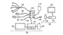
図1は、本発明の一実施の形態に係る生体情報モニタシステムの構成を示す図である。 FIG. 1 is a diagram showing a configuration of a biological information monitor system according to an embodiment of the present invention.
図1の生体情報モニタシステムは、病室、手術室または集中治療室において患者のそばに置かれたベッドサイドモニタ装置100と、患者から離れた場所(例えばナースステーションなど)に置かれたセントラルモニタ装置120とからなる。ベッドサイドモニタ装置100は、ベッドサイドモニタ装置本体101、マルチポートモジュール102、ベッドサイドモニタ表示部103、テレメータ送信機104、心電ケーブル105、第1観血血圧ケーブル106、第2観血血圧ケーブル107、体温プローブ108、酸素飽和度(SpO2)センサ109およびカフ110を有する。セントラルモニタ装置120は、セントラルモニタ装置本体121、テレメータ受信機122およびセントラルモニタ表示部123を有する。なお、一般に、生体情報モニタシステムは、1台のセントラルモニタ装置120に対して複数台のベッドサイドモニタ装置100を接続することができるが、本実施の形態では説明を簡単にするために1台のベッドサイドモニタ装置100のみ開示する。The biological information monitor system of FIG. 1 includes a
ベッドサイドモニタ装置本体101は、信号処理回路(CPU)およびメモリを有し、メモリには、後で詳しく説明する警報表示方法をCPUに実現させるためのプログラムが予め記憶されている。また、ベッドサイドモニタ装置本体101は、後述するタッチパネルからの入力によりベッドサイドモニタ表示部103から通知された設定事項をメモリに記憶する。これにより、記憶された設定事項に応じた警報表示方法がCPUにより実現される。 The bedside monitor apparatus
ベッドサイドモニタ装置本体101には、マルチポートモジュール102、ベッドサイドモニタ表示部103およびテレメータ送信機104がそれぞれケーブルを介して接続されている。ベッドサイドモニタ装置本体101は、マルチポートモジュール102から取得された生体情報データを受信して、これをベッドサイドモニタ表示部103およびテレメータ送信機104に出力する。また、ベッドサイドモニタ装置本体101は、転送された生体情報データのうちの計測値データを予め設定された閾値を比較すると共に、転送された生体情報データのうちの波形データを分析して、それらの結果に応じた警報データを生成して、これを生体情報と一緒にベッドサイドモニタ表示部103およびテレメータ送信機104に出力する。また、上記比較の結果や上記分析の結果は、メモリに読み出し可能に記憶される。なお、上記比較結果や上記分析結果が何らかの異常を呈した場合に備えて、様々な異常に対する対処法についての情報なども、メモリに予め記憶されていることが好ましい。 A
テレメータ送信機104は、ベッドサイドモニタ装置本体101から入力された生体情報データおよび警報データをセントラルモニタ装置120に無線送信する。無線送信された生体情報データおよび警報データは、テレメータ受信機122を介してセントラルモニタ装置本体121により受信され、セントラルモニタ表示部123に表示される。なお、警報データは、セントラルモニタ表示部123に内蔵されたスピーカから音声として出力されてもよい。 The
表示手段としてのベッドサイドモニタ表示部103は、ベッドサイドモニタ装置本体101から入力された生体情報データおよび警報データを画面に表示する。なお、警報データは、ベッドサイドモニタ表示部103に内蔵されたスピーカから音声として出力されてもよい。 The bedside
また、ベッドサイドモニタ表示部103は、ユーザインタフェースとしてタッチパネル機能を有し、医療スタッフが画面に触れると画面上の接触位置に対応付けられた設定事項がベッドサイドモニタ装置本体101に通知される。 The bedside
マルチポートモジュール102には、心電ケーブル105、第1観血血圧ケーブル106、第2観血血圧ケーブル107、体温プローブ108、酸素飽和度センサ109およびカフ110が接続されている。心電ケーブル105は、心電図のセンサと呼吸のセンサとの双方を兼ねており、患者体表上の複数箇所に装着された電極により、生体から出力される電気信号を検出して、これを表す検出信号を得る。第1観血血圧ケーブル106は、患者の特定部位の動脈または静脈に挿入されたトランスデューサにより、第1観血血圧値を検出して、これを表す検出信号を得る。第2観血血圧ケーブル107は、患者の、第1観血血圧ケーブル106とは別の部位の動脈または静脈に挿入されたトランスデューサにより、第2観血血圧値を検出して、これを表す検出信号を得る。体温プローブ108は、患者体表上の特定部位に装着され、体温値を検出して、これを表す検出信号を得る。酸素飽和度センサ109は、患者体表上の特定部位に装着され、光吸収率値を検出して、これを表す検出信号を得る。カフ110は、患者体表上の特定部位に装着され、装着部位の非観血血圧値を検出して、これを表す検出信号を得る。なお、以下の説明では、心電ケーブル105、第1観血血圧ケーブル106、第2観血血圧ケーブル107、体温プローブ108、酸素飽和度センサ109およびカフ110のうち、1または2以上のものに言及するとき、「生体情報センサ」という。 The
マルチポートモジュール102は、各生体情報センサにより検出された値を表すアナログ信号に対して、増幅やA/D変換(アナログディジタル変換)などを含む信号処理を行うことにより、各種の生体情報を表すディジタルデータ(生体情報データ)を生成する。具体的には、心電ケーブル105の検出信号からは、心電図データ(心電波形データを含む)、心拍数データ(心拍数計測値データを含む)および呼吸数データ(呼吸波形データおよび呼吸数計測値データを含む)が得られ、第1観血血圧ケーブル106の検出信号からは、第1観血血圧データ(第1観血血圧波形データおよび第1観血血圧計測値データを含む)が得られ、第2観血血圧ケーブル107の検出信号からは、第2観血血圧データ(第2観血血圧波形データおよび第2観血血圧計測値データを含む)が得られ、体温プローブ108の検出信号からは、体温データ(体温波形データおよび体温計測値データを含む)が得られ、酸素飽和度センサ109の検出信号からは、酸素飽和度データ(酸素飽和度波形データおよび酸素飽和度計測値データを含む)が得られ、カフ110の検出信号からは、非観血血圧データ(非観血血圧計測値データを含む)が得られる。マルチポートモジュール102は、これらの生体情報データをベッドサイドモニタ装置本体101に転送する。 The
次いで、上記構成を有する生体情報モニタシステムにおいて実行される警報表示方法について図2〜図4を参照しながら説明する。 Next, an alarm display method executed in the biological information monitoring system having the above configuration will be described with reference to FIGS.
まず図2を参照して、警報インジケータの表示形式について説明する。 First, the display format of the alarm indicator will be described with reference to FIG.
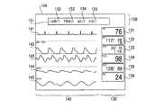
ベッドサイドモニタ表示部103の液晶表示画面(以下、単に「画面」という)128は、計測値データ表示部130と、波形データ表示部140と、警報データ表示部150とに分けられている。これらの表示部は、互いに画面128上で互いに重複することなく離間配置されている。 A liquid crystal display screen (hereinafter simply referred to as “screen”) 128 of the bedside
計測値データ表示部130は、各生体情報の計測値を表示する部分であり、この部分には、画面128の上から順に、心拍数(HR)計測値データを表示する領域である心拍数表示ウィンドウ131、第1観血血圧(BP1)計測値データを表示する領域である第1観血血圧表示ウィンドウ132、第2観血血圧(BP2)計測値データを表示する領域である第2観血血圧表示ウィンドウ133、酸素飽和度(SpO2)計測値データを表示する領域である酸素飽和度表示ウィンドウ134、非観血血圧(NIBP)計測値データを表示する領域である非観血血圧表示ウィンドウ135、および呼吸数(RR)計測値データを表示する領域である呼吸数表示ウィンドウ136が、表示されている。なお、表示される計測値データ表示ウィンドウ、その表示順およびその表示色は、医療スタッフの設定操作により適宜変更可能である。The measurement value
波形データ表示部140は、各生体情報の波形を表示する部分であり、この部分には、画面128の上から順に、心電波形データ141、第1観血血圧波形データ142、第2観血血圧波形データ143、酸素飽和度波形データ144および呼吸波形データ145が、表示されている。なお、表示される波形、その表示順およびその表示色は、医療スタッフの設定操作により適宜変更可能である。 The waveform
警報データ表示部150は、各生体情報に関する警報データを表示する部分であり、この部分には、警報データを表示する領域である警報データ表示ウィンドウ151が表示され、その中には、画面128の左から順に、心拍数警報インジケータ152、不整脈警報インジケータ153、血圧警報インジケータ154および呼吸警報インジケータ155が、表示されている。なお、表示される警報インジケータ、その表示順およびその表示色は、予め決められており、医療スタッフの設定操作により変更することはできない。 The alarm
ここで、ベッドサイドモニタ装置本体101が、心電図データを分析した結果、何らかの不整脈を認めたとする。この場合、不整脈警報データを生成してベッドサイドモニタ表示部103に出力する。その結果、不整脈警報インジケータ153が、例えば白色の一重丸印として表示されている他の警報インジケータに比べて目立つように、例えば赤色で塗りつぶされた丸印として表示される。 Here, it is assumed that the bedside monitor apparatus
このように、生体情報に関する警報データを、その生体情報の計測値を表示する領域(つまり計測値データ表示ウィンドウ)から離間した領域(つまり警報データ表示ウィンドウ)に表示することにより、医療スタッフにとって判りやすく警報を表示することができる。 In this way, the alarm data regarding the biometric information is displayed in a region (that is, the alarm data display window) that is separated from the region that displays the measurement value of the biometric information (that is, the measurement value data display window). An alarm can be displayed easily.
また、上記の例のように不整脈警報データが表示された場合に、医療スタッフが、画面128の、警報データ表示ウィンドウ151の部分もしくは不整脈警報インジケータ153の部分またはその周辺部分に触れると、これに応答してベッドサイドモニタ装置本体101が、分析結果により認められた不整脈の詳細情報や、それに対する対処法などをメモリから読み出してベッドサイドモニタ表示部103に出力し、ベッドサイドモニタ表示部103は、画面128に新たなウィンドウを表示し、このウィンドウの中に、上記詳細情報や対処法情報を画面128に表示することが好ましい。これにより、医療スタッフの習熟度とは無関係に、如何なる医療スタッフであっても即座に緊急事態に対処することができる。 Further, when the arrhythmia alarm data is displayed as in the above example, when the medical staff touches the alarm data display
続いて図3を参照して、警報インジケータの表示態様変更の一例について説明する。 Next, an example of changing the display mode of the alarm indicator will be described with reference to FIG.
ベッドサイドモニタ装置本体101が、心電図データを分析した結果、何らかの比較的重篤な不整脈を認めたとする。この場合、緊急度が高いことを示す不整脈警報データを生成してベッドサイドモニタ表示部103に出力する。また、これと同時に、ベッドサイドモニタ装置本体101が、心拍数計測値データを閾値と比較した結果、呼吸数が平常時よりも若干高めであることを認めたとする。この場合、緊急度が低いことを示す心拍数警報データを生成してベッドサイドモニタ表示部103に出力する。 Assume that the bedside monitor apparatus
この結果、不整脈警報インジケータ153は、緊急度が高いことを示す赤色で塗りつぶされた丸印として表示され、これと同時に、心拍数警報インジケータ152は、緊急度が低いことを示すシアンで塗りつぶされた丸印として表示される。さらに、これと同時に、従来の警報表示方法と同様に、心拍数表示ウィンドウ131の内部の文字・マークおよび背景が点滅する。なお、さらにこれと同時に、心電波形データ141が他の波形データに比べて目立つように、波形データの表示態様を変更してもよい。 As a result, the
このように、警報インジケータの表示態様を緊急度の高さに応じて変更することにより、複数種類の生体情報が異常を呈した場合でも、医療スタッフは、何を優先的に対処すべきかを把握することができ、より確実に患者に対して適切な処理を施すことができる。また、表示態様の変更手法として表示色の変更を採用することにより、医療スタッフは、優先的に対処すべきことを即座に把握することができる。 In this way, by changing the display mode of the alarm indicator according to the level of urgency, even when multiple types of biological information exhibit abnormalities, the medical staff knows what to preferentially deal with It is possible to perform appropriate processing on the patient more reliably. In addition, by adopting the display color change as the display mode change method, the medical staff can immediately grasp what should be preferentially dealt with.
なお、上記の例において、緊急度が高いと判断される不整脈としては、様々なものが挙げられるが、少なくともASYSTOLE(心停止)やVF(心室細動)、VT(心室粗動)などが含まれる。 In the above example, the arrhythmia determined to have a high degree of urgency includes various types of arrhythmia, but includes at least ASYSOLE (cardiac arrest), VF (ventricular fibrillation), VT (ventricular flutter), etc. It is.
また、どのような異常を呈した場合に緊急度を高いと判断し、どのような異常を呈した場合に緊急度を低いと判断するかについては、医療スタッフが、その判断指標(例えば閾値)を生体情報毎に個別に設定することができる。また、上記の例では、警報インジケータの表示色を赤色・シアンで区別することにより緊急度の高さを2段階で表現しているが、他の方法を用いることもできる。例えば、緊急度が高い場合には赤色を、緊急度が中間程度である場合には黄色を、緊急度が低い場合にはシアンを、警報インジケータの表示色とすることができる。 In addition, the medical staff determines which abnormality is present when the urgency level is high and what abnormality is determined when the urgency level is low. Can be individually set for each piece of biological information. In the above example, the level of urgency is expressed in two stages by distinguishing the display color of the alarm indicator by red and cyan, but other methods can also be used. For example, the alarm indicator can be displayed in red when the urgency level is high, yellow when the urgency level is intermediate, and cyan when the urgency level is low.
また、上記の例では、生体情報の種類毎に緊急度の高さを判断することで警報インジケータの表示態様の変更を行う場合について説明したが、生体情報の種類間の相対的な緊急度の高さを判断することで警報インジケータの表示態様の変更を行ってもよい。例えば、酸素飽和度と心拍数とに関して、計測値データに異常が認められた場合は、ベッドサイドモニタ装置本体101は、これらの生体情報間の相対的な緊急度の高さを判断し、例えば相対的に緊急度の高い生体情報である酸素飽和度に対して、緊急度が高いことを示す警報データを生成し、相対的に緊急度の低い生体情報である心拍数に対して、緊急度が低いことを示す警報データを生成する。この結果、ベッドサイドモニタ表示部103は、酸素飽和度警報インジケータ(図示せず)を赤色で塗りつぶされた丸印として表示し、心拍数警報インジケータ152をシアンで塗りつぶされた丸印として表示する。 In the above example, the case where the display mode of the alarm indicator is changed by determining the level of urgency for each type of biological information has been described. You may change the display mode of an alarm indicator by judging height. For example, when an abnormality is recognized in the measurement value data regarding the oxygen saturation and the heart rate, the bedside monitor apparatus
ちなみに、例えば酸素飽和度のように、異常を呈した場合は大抵緊急対応を要する生体情報に関しては、異常が生じたときに緊急度の高さの判断を行わずに必ず赤色で警報インジケータを表示する一方、例えば体温のように、場合によっては緊急対応を必要としない生体情報に関しては、異常が生じたときに緊急度の高さの判断を行ったうえで判断結果に応じた色で警報インジケータを表示するようにしてもよい。 By the way, for example, when there is an abnormality such as oxygen saturation, biological information that usually requires an emergency response always displays a warning indicator in red without making a judgment on the level of urgency when an abnormality occurs. On the other hand, for biological information that does not require emergency response in some cases, such as body temperature, an alarm indicator is displayed in a color according to the determination result after determining the level of urgency when an abnormality occurs May be displayed.
続いて図4を参照して、警報インジケータの表示態様変更の他の例について説明する。 Next, another example of changing the display mode of the alarm indicator will be described with reference to FIG.
ベッドサイドモニタ装置本体101が、医療スタッフの設定により、心電図データ、心拍数データ、第1観血血圧データ、第2観血血圧データ、酸素飽和度データおよび非観血血圧データを受信し、呼吸数データの表示を選択していないとする。この場合、ベッドサイドモニタ装置本体101は、心電図データ、心拍数データ、第1観血血圧データ、第2観血血圧データ、酸素飽和度データおよび非観血血圧データを表示するが、呼吸数データ、つまり、呼吸波形データおよび呼吸数計測値データは、表示されない。そして、対応する生体情報データが取得中である警報インジケータ(つまり、心拍数警報インジケータ152、不整脈警報インジケータ153および血圧警報インジケータ154)は、実線の丸印として表示される一方、対応する生体情報データが取得中でない呼吸警報インジケータ155は、破線の丸印として表示される。ただし、表示される警報インジケータおよびその表示順は、対応する生体情報データが取得中か否かとは無関係に、常に一定である。これにより、警報インジケータの表示を一層判りやすくすることができる。 The bedside monitor
なお、対応する生体情報データの表示が選択中であるか否かに応じて警報インジケータの表示態様を変更する手法は、適宜変更可能である。例えば、警報データ表示ウィンドウを、心拍数警報インジケータ152に割り当てられた領域156、不整脈警報インジケータ153に割り当てられた領域157、血圧警報インジケータ154に割り当てられた領域158および呼吸警報インジケータ155に割り当てられた領域159に分け、これらの領域内に表示されている文字やインジケータの明度を変更することにより警報インジケータの表示態様を変更してもよい。例えば上記の例のように、呼吸数データが取得中でない場合は、呼吸警報インジケータ155およびその横に表示されている文字「呼吸」を、他の領域内の文字やインジケータに比べて、暗い色で表示したり、他の領域の背景色に近い色で表示したりしてもよい。この場合も、警報インジケータの表示を一層判りやすくすることができる。 Note that the method of changing the display mode of the alarm indicator depending on whether or not the display of the corresponding biological information data is being selected can be changed as appropriate. For example, the alarm data display window was assigned to the
以上、本発明の実施の形態について説明した。なお、以上の説明は本発明の好適な実施の形態の例証であり、本発明の範囲はこれに限定されない。つまり、上記装置の構成および動作についての説明は一例であり、本発明の範囲においてこれらの例に対する様々な変更や追加が可能であることは明らかである。 The embodiment of the present invention has been described above. The above description is an illustration of a preferred embodiment of the present invention, and the scope of the present invention is not limited to this. That is, the description of the configuration and operation of the above apparatus is an example, and it is apparent that various modifications and additions to these examples are possible within the scope of the present invention.
例えば、本実施の形態でモニタされる生体情報は適宜変更可能であり、各生体情報の検出方式も適宜変更可能である。さらに、ベッドサイドモニタ装置本体101は、マルチポートモジュール102、ベッドサイドモニタ表示部103およびテレメータ送信機104の一部または全部とケーブルを介して接続する代わりに一体化されていてもよい。 For example, the biological information monitored in the present embodiment can be changed as appropriate, and the detection method of each biological information can also be changed as appropriate. Further, the bedside monitor apparatus
また、本実施の形態では、警報データは、ベッドサイドモニタ表示部103の液晶表示画面128内に表示されるが、ベッドサイドモニタ表示部103の筐体の一部に、複数色で発光可能なLED(Light Emitting Diode)を設けることでも、本実施の形態と同様の作用効果を実現することができる。 In this embodiment, the alarm data is displayed in the liquid
また、本実施の形態では、正常に計測された生体情報が異常を呈した場合を前提として、警報表示方法を説明したが、他の場合にもこの警報表示方法を利用することができる。 In the present embodiment, the alarm display method has been described on the assumption that the biological information measured normally exhibits an abnormality. However, the alarm display method can be used in other cases.
例えば、生体情報センサの離脱などにより生体情報が正常に計測されなくなった場合(つまり生体情報計測エラーの場合)にも、その旨を通知するために本実施の形態の警報表示方法を利用することができる。この場合、生体情報計測エラーを通知するための警報インジケータが上記の警報インジケータと同様に設けられることが好ましい。 For example, even when the biological information is not normally measured due to the detachment of the biological information sensor or the like (that is, in the case of a biological information measurement error), the alarm display method of the present embodiment is used to notify that fact. Can do. In this case, it is preferable that an alarm indicator for notifying a biological information measurement error is provided in the same manner as the alarm indicator.
また、本実施の形態のベッドサイドモニタ装置100が、病院内の他のシステム、例えば電子カルテシステムと通信して、患者への投薬関連情報をベッドサイドモニタ装置本体101に取り込むことが可能な場合は、不適切な投薬(例えば、薬剤の種類の誤り、投薬量の誤り、投薬忘れなど)が行われた場合にも、その旨を通知するために本実施の形態の警報表示方法を利用することができる。この場合、投薬エラーを通知するための警報インジケータが上記の警報インジケータと同様に設けられることが好ましい。 In addition, when the
100 ベッドサイドモニタ装置
103 ベッドサイドモニタ表示部
130 計測値データ表示部
131 心拍数表示ウィンドウ
132 第1観血血圧表示ウィンドウ
133 第2観血血圧表示ウィンドウ
134 酸素飽和度表示ウィンドウ
135 非観血血圧表示ウィンドウ
136 呼吸数表示ウィンドウ
140 波形データ表示部
150 警報データ表示部
151 警報データ表示ウィンドウ
152 心拍数警報インジケータ
153 不整脈警報インジケータ
154 血圧警報インジケータ
155 呼吸警報インジケータDESCRIPTION OF
Claims (3)
Translated fromJapanese取得された前記計測値データを第1の領域に表示すると同時に、取得された前記警報データを前記第1の領域から離間した第2の領域に表示する表示手段と
を有し、
前記表示手段は、前記第2の領域において、所定の複数の生体情報の各々に個別表示領域を割り当て、前記所定の複数の生体情報の各々について、計測値データが取得中である場合、実線の丸印で表示する一方、計測値データが取得中でない場合、破線の丸印で表示する
ことを特徴とする生体情報モニタ装置。Acquisition means for acquiring measurement value data of biological information and alarm data related to the biological information;
Displaying the acquired measurement value data in the first area, and simultaneously displaying the acquired alarm data in a second area spaced from the first area, and
In the second area, the display means allocates an individual display area to each of the predetermined plurality of pieces of biological information, and when measurement value data is being acquired for each of the plurality of pieces of predetermined pieces of biological information, On the other hand, when the measured value data is not being acquired, the biological information monitoring apparatus isdisplayed with a dotted circle .
生体情報の計測値データと、前記生体情報に関する警報データとを取得する取得ステップと、
取得された前記計測値データを第1の領域に表示すると同時に、取得された前記警報データを前記第1の領域から離間した第2の領域に表示する表示ステップと
を有し、
前記表示ステップは、前記第2の領域において、所定の複数の生体情報の各々に個別表示領域を割り当て、前記所定の複数の生体情報の各々について、計測値データが取得中である場合、実線の丸印で表示する一方、計測値データが取得中でない場合、破線の丸印で表示する
ことを特徴とする警報表示方法。An alarm display method in a biological information monitor device,
An acquisition step of acquiring measurement value data of biological information and alarm data related to the biological information;
Displaying the acquired measurement value data in the first area, and simultaneously displaying the acquired alarm data in a second area separated from the first area, and
The display step assigns an individual display area to each of the predetermined plurality of biological information in the second area, and when the measurement value data is being acquired for each of the predetermined plurality of biological information, A warning display method, characterizedin that when a measurement value data is not being acquired, a circle is displayed with a broken line when it isdisplayed with a circle .
取得された前記計測値データを第1の領域に表示すると同時に、取得された前記警報データを前記第1の領域から離間した第2の領域に表示する表示ステップであって、前記第2の領域において、所定の複数の生体情報の各々に個別表示領域を割り当て、前記所定の複数の生体情報の各々について、計測値データが取得中である場合、実線の丸印で表示する一方、計測値データが取得中でない場合、破線の丸印で表示する表示ステップと
を生体情報モニタ装置に設けられたコンピュータに実行させる警報表示プログラム。An acquisition step of acquiring measurement value data of biological information and alarm data related to the biological information;
A display step of displaying the acquired measurement value data in the first area and simultaneously displaying the acquired alarm data in a second area separated from the first area, wherein the second area In this case, an individual display area is assigned to each of the predetermined plurality of biological information, and when the measurement value data is being acquired for each of the predetermined plurality of biological information, the measurement value data A warning display program for causing a computer provided in the biological information monitor device to executea display stepof displaying with a dotted-line circle when is not being acquired .
Priority Applications (1)
| Application Number | Priority Date | Filing Date | Title |
|---|---|---|---|
| JP2007036570AJP5148891B2 (en) | 2007-02-16 | 2007-02-16 | Biological information monitor device, alarm display method, and alarm display program |
Applications Claiming Priority (1)
| Application Number | Priority Date | Filing Date | Title |
|---|---|---|---|
| JP2007036570AJP5148891B2 (en) | 2007-02-16 | 2007-02-16 | Biological information monitor device, alarm display method, and alarm display program |
Publications (2)
| Publication Number | Publication Date |
|---|---|
| JP2008200111A JP2008200111A (en) | 2008-09-04 |
| JP5148891B2true JP5148891B2 (en) | 2013-02-20 |
Family
ID=39778210
Family Applications (1)
| Application Number | Title | Priority Date | Filing Date |
|---|---|---|---|
| JP2007036570AActiveJP5148891B2 (en) | 2007-02-16 | 2007-02-16 | Biological information monitor device, alarm display method, and alarm display program |
Country Status (1)
| Country | Link |
|---|---|
| JP (1) | JP5148891B2 (en) |
Cited By (1)
| Publication number | Priority date | Publication date | Assignee | Title |
|---|---|---|---|---|
| CN111248864A (en)* | 2020-01-20 | 2020-06-09 | 康泰医学系统(秦皇岛)股份有限公司 | Display interface of detection equipment and display method of display interface |
Families Citing this family (16)
| Publication number | Priority date | Publication date | Assignee | Title |
|---|---|---|---|---|
| JP5719520B2 (en)* | 2010-03-05 | 2015-05-20 | フクダ電子株式会社 | Biological information monitor device, screen display method, and screen display program |
| EP2638511A4 (en) | 2010-11-11 | 2014-09-03 | Zoll Medical Corp | DASHBOARD OF SHORT-TERM CARE TREATMENT SYSTEM |
| RU2631187C2 (en)* | 2011-03-28 | 2017-09-19 | Конинклейке Филипс Н.В. | System and method for family mode provision for monitors |
| JP5543399B2 (en) | 2011-04-12 | 2014-07-09 | 日本光電工業株式会社 | Biological information monitoring device |
| US9730648B2 (en) | 2013-03-14 | 2017-08-15 | DePuy Synthes Products, Inc. | Methods, systems, and devices for monitoring and displaying medical parameters for a patient |
| JP6227289B2 (en)* | 2013-06-14 | 2017-11-08 | フクダ電子株式会社 | Biological information monitoring device |
| JP7055586B2 (en)* | 2015-02-27 | 2022-04-18 | フクダ電子株式会社 | Biometric information monitor |
| JP6788959B2 (en)* | 2015-04-28 | 2020-11-25 | フクダ電子株式会社 | Biological information monitoring device and its control method |
| JP6938711B2 (en)* | 2016-02-26 | 2021-09-22 | フクダ電子株式会社 | Biometric information monitoring system and biometric information monitor |
| JP6938710B2 (en)* | 2016-02-26 | 2021-09-22 | フクダ電子株式会社 | Biometric information monitoring system and biometric information monitor |
| JP2019144730A (en)* | 2018-02-19 | 2019-08-29 | 株式会社高山商事 | Watching support system |
| JP6874048B2 (en)* | 2019-04-12 | 2021-05-19 | パラマウントベッド株式会社 | State judgment device |
| EP3783580B1 (en)* | 2019-08-23 | 2022-08-10 | Koninklijke Philips N.V. | Generating a clinician-perceptible output responsive to a subject-monitoring device |
| JP7449065B2 (en) | 2019-10-11 | 2024-03-13 | 日本光電工業株式会社 | Biological information processing device, biological information processing method, program and storage medium |
| WO2021202213A2 (en) | 2020-03-30 | 2021-10-07 | Zoll Medical Corporation | Medical device system and hardware for sensor data acquisition |
| WO2022051672A1 (en) | 2020-09-04 | 2022-03-10 | Zoll Medical Corporation | Medical treatment system with companion device |
Family Cites Families (17)
| Publication number | Priority date | Publication date | Assignee | Title |
|---|---|---|---|---|
| JP3191409B2 (en)* | 1991-05-10 | 2001-07-23 | 富士ゼロックス株式会社 | Font data generator |
| JPH05300881A (en)* | 1991-05-21 | 1993-11-16 | Fukuda Denshi Co Ltd | Biometric information processing device |
| JPH0564630A (en)* | 1991-05-22 | 1993-03-19 | Fukuda Denshi Co Ltd | Living body information processor |
| US5262944A (en)* | 1992-05-15 | 1993-11-16 | Hewlett-Packard Company | Method for use of color and selective highlighting to indicate patient critical events in a centralized patient monitoring system |
| JPH08215150A (en)* | 1995-02-09 | 1996-08-27 | Canon Inc | Ophthalmic diagnostic device |
| US5772599A (en)* | 1996-05-09 | 1998-06-30 | Albert Einstein Healthcare Network | Apparatus and method for monitoring a system |
| US7565905B2 (en)* | 1998-06-03 | 2009-07-28 | Scott Laboratories, Inc. | Apparatuses and methods for automatically assessing and monitoring a patient's responsiveness |
| JP3284545B2 (en)* | 1999-04-26 | 2002-05-20 | ソニー株式会社 | Information processing apparatus, information processing method, and program storage medium |
| JP3758132B2 (en)* | 1999-10-12 | 2006-03-22 | 株式会社タニタ | Biometric device |
| US6707476B1 (en)* | 2000-07-05 | 2004-03-16 | Ge Medical Systems Information Technologies, Inc. | Automatic layout selection for information monitoring system |
| JP4189787B2 (en)* | 2001-03-06 | 2008-12-03 | 日本光電工業株式会社 | Biological information display monitor and system |
| JP2004194996A (en)* | 2002-12-19 | 2004-07-15 | Fukuda Denshi Co Ltd | Biological information display device |
| JP4495577B2 (en)* | 2004-11-26 | 2010-07-07 | ニッタン株式会社 | Disaster prevention receiver |
| AU2006204886B2 (en)* | 2005-01-13 | 2011-08-04 | Welch Allyn, Inc. | Vital signs monitor |
| CA2620302A1 (en)* | 2005-03-02 | 2006-09-08 | Spacelabs Healthcare, Llc | Trending display of patient wellness |
| JP2006263384A (en)* | 2005-03-25 | 2006-10-05 | Toshiba Corp | Warning notification system |
| JP5399602B2 (en)* | 2005-04-22 | 2014-01-29 | フクダ電子株式会社 | Biological information output device and method, and biological information report |
- 2007
- 2007-02-16JPJP2007036570Apatent/JP5148891B2/enactiveActive
Cited By (1)
| Publication number | Priority date | Publication date | Assignee | Title |
|---|---|---|---|---|
| CN111248864A (en)* | 2020-01-20 | 2020-06-09 | 康泰医学系统(秦皇岛)股份有限公司 | Display interface of detection equipment and display method of display interface |
Also Published As
| Publication number | Publication date |
|---|---|
| JP2008200111A (en) | 2008-09-04 |
Similar Documents
| Publication | Publication Date | Title |
|---|---|---|
| JP5148891B2 (en) | Biological information monitor device, alarm display method, and alarm display program | |
| KR102615025B1 (en) | Spot check measurement system | |
| CN103800002B (en) | Biological information display device and biological information display system | |
| JP5584413B2 (en) | Patient monitoring system and monitoring method | |
| JP6066784B2 (en) | MEDICAL DEVICE MEASUREMENT INFORMATION MONITOR DEVICE AND MEDICAL DEVICE MEASUREMENT INFORMATION MONITOR SYSTEM | |
| US20040054261A1 (en) | Vital sign display method, vital sign display monitor, and system thereof | |
| US9402585B2 (en) | Biological information monitor and biological information monitoring system | |
| EP2762063B1 (en) | Physiological data monitor | |
| JP7230108B2 (en) | Patient monitor | |
| JP2018512237A (en) | A tool for recommendation of ventilation treatment guided by risk score for acute respiratory distress syndrome (ARDS) | |
| JP3682617B2 (en) | Vertical split display method for multiple patient data | |
| JP6868338B2 (en) | Biological information display device | |
| JP7055586B2 (en) | Biometric information monitor | |
| US20180263558A1 (en) | A physiological monitoring kit with usb drive | |
| US10368812B2 (en) | System for the early detection of life-threatening conditions of persons | |
| JP5385536B2 (en) | Biological information monitor | |
| JP2010063486A (en) | Biological data monitoring device | |
| JP7347921B2 (en) | Alarm information processing device and alarm information processing program | |
| JP6975016B2 (en) | Condition change discriminator | |
| CN112996435A (en) | Monitoring method based on physiological parameters, monitoring equipment and computer storage medium | |
| JP7444907B2 (en) | Biological information monitor, biological information monitoring system and display method | |
| JP7106253B2 (en) | Bedside monitor and vital information monitoring system | |
| CN104905768A (en) | Biological information measurement and display apparatus |
Legal Events
| Date | Code | Title | Description |
|---|---|---|---|
| A621 | Written request for application examination | Free format text:JAPANESE INTERMEDIATE CODE: A621 Effective date:20091208 | |
| A131 | Notification of reasons for refusal | Free format text:JAPANESE INTERMEDIATE CODE: A131 Effective date:20111122 | |
| A977 | Report on retrieval | Free format text:JAPANESE INTERMEDIATE CODE: A971007 Effective date:20111124 | |
| A521 | Request for written amendment filed | Free format text:JAPANESE INTERMEDIATE CODE: A523 Effective date:20120120 | |
| A131 | Notification of reasons for refusal | Free format text:JAPANESE INTERMEDIATE CODE: A131 Effective date:20120424 | |
| A521 | Request for written amendment filed | Free format text:JAPANESE INTERMEDIATE CODE: A523 Effective date:20120622 | |
| TRDD | Decision of grant or rejection written | ||
| A01 | Written decision to grant a patent or to grant a registration (utility model) | Free format text:JAPANESE INTERMEDIATE CODE: A01 Effective date:20121120 | |
| A61 | First payment of annual fees (during grant procedure) | Free format text:JAPANESE INTERMEDIATE CODE: A61 Effective date:20121129 | |
| R150 | Certificate of patent or registration of utility model | Free format text:JAPANESE INTERMEDIATE CODE: R150 Ref document number:5148891 Country of ref document:JP Free format text:JAPANESE INTERMEDIATE CODE: R150 | |
| FPAY | Renewal fee payment (event date is renewal date of database) | Free format text:PAYMENT UNTIL: 20151207 Year of fee payment:3 | |
| R250 | Receipt of annual fees | Free format text:JAPANESE INTERMEDIATE CODE: R250 | |
| R250 | Receipt of annual fees | Free format text:JAPANESE INTERMEDIATE CODE: R250 | |
| R250 | Receipt of annual fees | Free format text:JAPANESE INTERMEDIATE CODE: R250 | |
| R250 | Receipt of annual fees | Free format text:JAPANESE INTERMEDIATE CODE: R250 | |
| R250 | Receipt of annual fees | Free format text:JAPANESE INTERMEDIATE CODE: R250 | |
| R250 | Receipt of annual fees | Free format text:JAPANESE INTERMEDIATE CODE: R250 | |
| R250 | Receipt of annual fees | Free format text:JAPANESE INTERMEDIATE CODE: R250 | |
| R250 | Receipt of annual fees | Free format text:JAPANESE INTERMEDIATE CODE: R250 | |
| R250 | Receipt of annual fees | Free format text:JAPANESE INTERMEDIATE CODE: R250 | |
| R250 | Receipt of annual fees | Free format text:JAPANESE INTERMEDIATE CODE: R250 |