JP5147989B2 - Signal transmission of multiple antenna configurations in wireless communication systems - Google Patents
Signal transmission of multiple antenna configurations in wireless communication systemsDownload PDFInfo
- Publication number
- JP5147989B2 JP5147989B2JP2011506502AJP2011506502AJP5147989B2JP 5147989 B2JP5147989 B2JP 5147989B2JP 2011506502 AJP2011506502 AJP 2011506502AJP 2011506502 AJP2011506502 AJP 2011506502AJP 5147989 B2JP5147989 B2JP 5147989B2
- Authority
- JP
- Japan
- Prior art keywords
- wireless communication
- configuration
- infrastructure component
- communication infrastructure
- controller
- Prior art date
- Legal status (The legal status is an assumption and is not a legal conclusion. Google has not performed a legal analysis and makes no representation as to the accuracy of the status listed.)
- Active
Links
- 238000004891communicationMethods0.000titleclaimsdescription105
- 230000008054signal transmissionEffects0.000title1
- 230000005540biological transmissionEffects0.000claimsdescription23
- 238000001228spectrumMethods0.000claimsdescription6
- 238000001514detection methodMethods0.000claimsdescription3
- 238000000034methodMethods0.000description12
- 230000006870functionEffects0.000description8
- 239000000969carrierSubstances0.000description6
- 238000010586diagramMethods0.000description4
- 230000007774longtermEffects0.000description3
- 230000000873masking effectEffects0.000description3
- 125000004122cyclic groupChemical group0.000description2
- 239000003607modifierSubstances0.000description2
- 230000008569processEffects0.000description2
- 238000012545processingMethods0.000description2
- 238000012795verificationMethods0.000description2
- 241000760358EnodesSpecies0.000description1
- 230000008859changeEffects0.000description1
- 238000012986modificationMethods0.000description1
- 230000004048modificationEffects0.000description1
- 230000011664signalingEffects0.000description1
- 238000012546transferMethods0.000description1
Images


Classifications
- H—ELECTRICITY
- H04—ELECTRIC COMMUNICATION TECHNIQUE
- H04L—TRANSMISSION OF DIGITAL INFORMATION, e.g. TELEGRAPHIC COMMUNICATION
- H04L1/00—Arrangements for detecting or preventing errors in the information received
- H04L1/0001—Systems modifying transmission characteristics according to link quality, e.g. power backoff
- H04L1/0023—Systems modifying transmission characteristics according to link quality, e.g. power backoff characterised by the signalling
- H04L1/0032—Without explicit signalling
- H—ELECTRICITY
- H04—ELECTRIC COMMUNICATION TECHNIQUE
- H04L—TRANSMISSION OF DIGITAL INFORMATION, e.g. TELEGRAPHIC COMMUNICATION
- H04L5/00—Arrangements affording multiple use of the transmission path
- H04L5/0001—Arrangements for dividing the transmission path
- H04L5/0014—Three-dimensional division
- H04L5/0023—Time-frequency-space
Landscapes
- Engineering & Computer Science (AREA)
- Signal Processing (AREA)
- Computer Networks & Wireless Communication (AREA)
- Quality & Reliability (AREA)
- Mobile Radio Communication Systems (AREA)
- Detection And Prevention Of Errors In Transmission (AREA)
- Error Detection And Correction (AREA)
- Radio Transmission System (AREA)
- Digital Transmission Methods That Use Modulated Carrier Waves (AREA)
Description
Translated fromJapaneseこの開示内容は、概して無線通信に関し、また、この開示内容は、特に無線通信システムにおける多重アンテナ構成の信号伝達に関する。 This disclosure relates generally to wireless communications, and this disclosure relates specifically to signaling of multiple antenna configurations in wireless communication systems.
3GPPでは、ユニバーサル・モバイル・テレコミュニケーション・システム(Universal Mobile Telecommunications Systems:UMTS)のロング・ターム・エボリューション(Long Term Evolution:LTE)では、多重アンテナの基地局送信を規定すべく4つのアンテナポートまで許可することが予定されており、また選択された物理チャネル送信に対して1、2、又は4つのアンテナポートを使用にすることが許可されている。物理放知放送チャネル(Physical Broadcast Channel: PBCH)は、後者のこれら3つ全てのアンテナポート構成を用いて送信され得る。基地局が同期チャネルを介してアンテナ構成を明確に信号伝達しないため、ユーザ装置(user equipment :UE)は、初期ネットワークアクセス手順の初期段階において得られた基地局アンテナ構成情報の案内無しにPBCHを復号化することが要求される。特に、PBCHを含むマスター情報ブロックは、内部の巡回冗長検査(cyclic redundancy check:CRC)を有する畳み込み符号化コードワードとして送信される。しかし、信号対雑音比が高い場合であっても、ユーザ装置は、共通の基準シンボル(RS)を単に検査することにより、存在するアンテナ数を特定することを失敗する可能性がある。同様に、許可されたアンテナ構成の各々に関連する送信ダイバーシティ方式の推定検証がPBCH CRC検証と組み合わせて行われる場合、ユーザ装置は、基地局のアンテナ構成を誤って特定する可能性がある。例えば、特定の空間周波数ブロック符号化(space-frequency block coding:SFBC)の2アンテナ送信ダイバーシティ方式を用いて送信する場合、ユーザ装置(UE)は、1アンテナ送信を(不正確に)推定した場合、PBCHコードワードを正確に復号化することができる。 In 3GPP, Long Term Evolution (LTE) of Universal Mobile Telecommunications Systems (UMTS) allows up to four antenna ports to define multi-antenna base station transmissions. And is allowed to use 1, 2, or 4 antenna ports for the selected physical channel transmission. A physical broadcast channel (PBCH) may be transmitted using all three of these latter antenna port configurations. Since the base station does not explicitly signal the antenna configuration via the synchronization channel, the user equipment (UE) can transmit the PBCH without guidance of the base station antenna configuration information obtained in the initial stage of the initial network access procedure. Decoding is required. In particular, the master information block including the PBCH is transmitted as a convolutional coded codeword having an internal cyclic redundancy check (CRC). However, even when the signal-to-noise ratio is high, the user equipment may fail to identify the number of antennas present by simply examining the common reference symbol (RS). Similarly, if the transmit diversity scheme estimation verification associated with each allowed antenna configuration is performed in combination with the PBCH CRC verification, the user equipment may erroneously identify the base station antenna configuration. For example, when transmitting using a two-antenna transmission diversity scheme of specific space-frequency block coding (SFBC), the user equipment (UE) estimates (inaccurately) one-antenna transmission , PBCH codeword can be accurately decoded.
3GPP R1−073970には、対応するPBCH送信に対して基地局のアンテナ構成情報を通信するためのいくつかの可能な方法が開示される。第1の方法では、OFDMシンボル及び副搬送波(例えば、資源要素(resource elements))に対するPBCHコードワードの割り当ては、多重アンテナ構成に応じて変更される。一方で、3GPP R1−074861では、資源要素へのPBCHコードワードの割り当てが多重アンテナ構成に応じて変更すべきではないことが提案されている。第2の方法によれば、PBCHコードワードは、異なる符号化手順を用いてスクランブルされ、スクランブル手順は、基地局のアンテナ構成に基づいて調整される。この方法では、ユーザ装置は、畳み込み復号化及びCRC検査を試みることに先だって、推定された多重アンテナ構成から生じる対数尤度比(Log-Likelihood ratios:LLR)を逆スクランブルすることが要求される。この第2の方法では、逆スクランブルは、各アンテナ構成の推定に必要である。第3の手法は、アンテナ構成に応じてアラモチ(Alamouti)符号(SFBC又はSFBC+周波数切換送信ダイバーシティ(Frequency Switched Transmit Diversity:FSTD))を変更する必要がある。これにより、ユーザ装置は、送信ダイバーシティの割り当て構成をサポートする必要がある。従って、さらに、アンテナ構成の判定においてユーザ装置を支援する簡単な手段が必要とされる。 3GPP R1-073970 discloses several possible methods for communicating base station antenna configuration information for corresponding PBCH transmissions. In the first method, the assignment of PBCH codewords to OFDM symbols and subcarriers (eg, resource elements) is changed according to the multiple antenna configuration. On the other hand, 3GPP R1-074861 proposes that the assignment of PBCH codewords to resource elements should not be changed according to the multiple antenna configuration. According to the second method, the PBCH codeword is scrambled using different coding procedures, and the scrambling procedure is adjusted based on the antenna configuration of the base station. In this method, the user equipment is required to descramble log-likelihood ratios (LLRs) resulting from the estimated multiple antenna configuration prior to attempting convolutional decoding and CRC checking. In this second method, descrambling is necessary for estimation of each antenna configuration. The third method needs to change the Alamouti code (SFBC or SFBC + Frequency Switched Transmit Diversity (FSTD)) according to the antenna configuration. Accordingly, the user equipment needs to support a transmission diversity allocation configuration. Therefore, there is a further need for simple means to assist the user equipment in determining the antenna configuration.
開示された種々の形態、特徴及び利点は、以下に記載された添付図面とともに詳細な説明を十分に考慮することで当業者に対して十分に明確となるだろう。図面は、明確にするために簡潔化され、必ずしも一定の縮尺で描かれていない。 The various forms, features and advantages disclosed will become more apparent to those skilled in the art upon careful consideration of the detailed description taken in conjunction with the accompanying drawings described below. The drawings are simplified for clarity and are not necessarily drawn to scale.
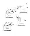
図1では、無線通信システム100は、地理的領域に配置されたネットワークを形成する1以上の固定基地基盤ユニット(fixed base infrastructure units)を備える。基地ユニットは、アクセスポイント、アクセス端末、基地、基地局、ノードB、eノードB、又は当該分野で用いられる専門用語により呼称される。図1では、サービスエリア、例えば、セル又はセル区域において、1以上の基地ユニット101,102は、多数のリモート・ユニット103,110と通信する。リモート・ユニットは、固定ユニット又は移動端末であってもよい。リモート・ユニットは、また、受信契約者ユニット、携帯電話、移動局、ユーザ、端末、受信契約者局、ユーザ装置(user equipment:UE)、又は当該分野で用いられる他の専門用語により呼称される。 In FIG. 1, the
概して、基地ユニット101,102は、ダウンリンク通信信号104,105を時間領域及び周波数領域の少なくとも一方で送信してリモート・ユニットと通信する。リモート・ユニット103,110は、アップリンク通信信号106,113により1以上の基地ユニットと通信する。1以上の基地ユニットは、ダウンリンク送信及びアップリンク送信を行うための1以上の送信機及び1以上の受信機を備える。また、リモート・ユニットは、1以上の送信機及び1以上の受信機を備える。 In general, the
一実施形態では、無線通信システムは、3GPPのユニバーサル・モバイル・テレコミュニケーション・システム(Universal Mobile Telecommunications System :UMTS)プロトコルにおける発展規格のロング・ターム・エボリューション(Long Term Evolution:LTE)に準拠し、基地局は、ダウンリンクにおいて、直交周波数分割多重(OFDM)変調方式を用いて送信し、ユーザ端末は、アップリンクにおいて、単一搬送波周波数分割多元接続方式(SC−FDMA)を用いて送信する。しかしながら、無線通信システムは、他の公開された又は独自の通信プロトコルを実施する。本発明は、いかなる特定の無線通信システム構造又はプロトコルの実施を制限することを意図しない。 In one embodiment, the wireless communication system conforms to the Long Term Evolution (LTE) evolution standard in 3GPP's Universal Mobile Telecommunications System (UMTS) protocol, Stations transmit on the downlink using an orthogonal frequency division multiplexing (OFDM) modulation scheme, and user terminals transmit on the uplink using a single carrier frequency division multiple access scheme (SC-FDMA). However, wireless communication systems implement other published or proprietary communication protocols. The present invention is not intended to limit the implementation of any particular wireless communication system structure or protocol.
いくつかのシステムでは、各基地局及び一般的には他の無線通信基盤構成要素が通信構成を有する。一実施形態では、通信構成は、基地局のアンテナ構成である。3GPPでは、例えば、ユニバーサル・モバイル・テレコミュニケーション・システム(UMTS)のロング・ターム・エボリューション(LTE)によって、多重アンテナ基地局の送信を規定すべく4つのアンテナポートまで許可することが予定されており、選択された物理チャネルの送信に関して1、2、又は4つのアンテナポートを使用することが許可されている。物理放知チャネル(Physical Broadcast Channel: PBCH)は、後者のこれら3つのアンテナポート構成の全てを用いて送信される。従って、無線通信を構成する複数の基地局は、異なるアンテナ構成を潜在的に有する。また、いくつかの実施形態では、1以上の基地端末のアンテナ構成は、動的に変更される。 In some systems, each base station and typically other wireless communication infrastructure components have a communication configuration. In one embodiment, the communication configuration is a base station antenna configuration. In 3GPP, for example, the Universal Mobile Telecommunications System (UMTS) Long Term Evolution (LTE) is planned to allow up to four antenna ports to regulate the transmission of multi-antenna base stations. , 1, 2, or 4 antenna ports are allowed to be used for transmission of the selected physical channel. A physical broadcast channel (PBCH) is transmitted using all of these latter three antenna port configurations. Thus, the plurality of base stations that make up wireless communication potentially have different antenna configurations. Also, in some embodiments, the antenna configuration of one or more base terminals is dynamically changed.
3GPPでは、現在、基地局は、同期チャネルを介して、アンテナ構成に関して明確に信号伝達しないため、ユーザ端末(UE)では、初期ネットワークアクセス手順の初期段階中に、得られた基地局アンテナ構成情報の案内無しにPBCHを復号化することが要求される。従って、特に、隣接した基地局が異なる構成を有する場合、及び基地局のアンテナ構成が動的に変化する場合の少なくとも一方の場合によっては、基地局のアンテナ構成を判別する際にユーザ端末を支援するための手段が望まれる。また、基地局が端末によって採用されるべき送信アンテナ構成に関して信号伝達することが望まれる場合があり得る。 In 3GPP, currently, the base station does not explicitly signal the antenna configuration via the synchronization channel, so the user terminal (UE) obtains the base station antenna configuration information obtained during the initial stage of the initial network access procedure. It is required to decode the PBCH without guidance. Therefore, especially when adjacent base stations have different configurations and / or when the base station antenna configuration dynamically changes, the user terminal is supported in determining the base station antenna configuration. A means for doing this is desired. It may also be desirable for the base station to signal regarding the transmit antenna configuration to be employed by the terminal.
本発明の開示は、特有の基地ユニットのアンテナ構成に関する判定をユーザ端末に通信すること、又は支援することの制限を意図しない。概して、無線通信基盤構成要素は、無線通信基盤構成要素の通信構成に関する判定と、無線通信端末のための通信構成、又は無線通信端末の通信構成に関する判定を用いて1以上の構成要素を支援する。例えば、通信構成情報は、以下に記載された何れか1以上の形式であり得る。その情報は、数ある情報の中で特に、無線通信端末のアンテナ構成、セル特定情報に関する情報(この情報は、場合によっては、例えば、同期チャネル識別子と関連して送信される)、フレーム構成又はスロット構成の期間に関係する情報、対の送信(例えば、周波数分割複信(FDD))又は対ではない送信(例えば、時分割複信(TDD))としてのセルの構成、対称又は非対称のダウンリンク周波数資源又はアップリンク周波数資源、送信されるパイロットシンボル又は基準シンボルの種類及び数のうちのいずれか一方、ブロードキャスト又はユニキャストのどちらのサービスをサポートしているかという情報、重畳されたチャネル送信の存在、許可制御データ、近接したスペクトル又は近接しないスペクトルの関連性、複数の搬送波構成の場合における利用可能な搬送波の数又は搬送波の関連性、1つの階層セル構成又は複数の搬送波の階層セル構成におけるセルの種類と搬送波の種類と他のセルに対する関係、及びSFN(single frequency network)のブロードキャスト専用搬送波である。 The present disclosure is not intended to be a limitation on communicating or assisting a user terminal with decisions regarding the antenna configuration of a particular base unit. In general, a wireless communication infrastructure component supports one or more components using a determination regarding a communication configuration of the wireless communication infrastructure component and a determination regarding a communication configuration for the wireless communication terminal or a communication configuration of the wireless communication terminal. . For example, the communication configuration information can be in any one or more of the formats described below. Among other information, the information includes, among other things, the antenna configuration of the wireless communication terminal, information about cell specific information (this information may be transmitted in some cases, for example, in association with a synchronization channel identifier), frame configuration or Information related to the duration of the slot configuration, cell configuration as paired transmission (eg frequency division duplex (FDD)) or non-paired transmission (eg time division duplex (TDD)), symmetric or asymmetric down Link frequency resource or uplink frequency resource, type and number of pilot symbols or reference symbols to be transmitted, information on whether broadcast or unicast service is supported, information on superimposed channel transmission Presence, admission control data, close spectrum or close spectrum association, multiple carriers The number of carriers that can be used or the relationship of carriers in the case of a cell structure, the relationship between the cell type and the carrier type and other cells in a hierarchical cell configuration or a hierarchical cell configuration of multiple carriers, and the SFN (single frequency network) ) Broadcast dedicated carrier.
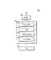
図2では、無線通信基盤構成要素200は、コントローラ220と通信可能に接続された送信機210を備える通信構成を有する。一実施形態では、無線通信基盤構成要素は、図1の基地ユニットのうちの1つの基地ユニットに対応し、通信構成は、アンテナ構成である。送信機は、概して、送信機のサービスエリア内で、1以上のユーザ端末と通信する。図2では、コントローラは、ソフトウェア、又はメモリ230に記憶されたファームウェアにより制御されるデジタルプロセッサとして、最も簡単に具体化される。代替的には、コントローラは、ハードウェアに相当する装置として、又はハードウェアとソフトウェアとの組み合わせとして具体化され得る。コントローラは、ユーザ端末に送信すべき情報ワードに基づいてパリティビットを生成するために用いられるパリティビット生成機能222を含む。従って、ソフトウェア及びファームウェアの少なくとも一方に制御されることにより、コントローラは、情報ワードに基づいてパリティビットを生成するように構成される。図3の処理フロー図300の310では、無線通信基盤構成要素は、情報ワード、例えば転送ブロックに基づいて、パリティビット、例えば、巡回冗長検査(CRC)を生成する。図2の223では、パリティビットは、情報ワードと結合される。 In FIG. 2, the wireless
図2では、コントローラは、パリティビットに基づいて、無線通信基盤構成要素の通信構成情報を符号化するために用いられるパリティビット符号化機能224を含む。コントローラは、ソフトウェア及びファームウェアの少なくとも一方に制御されることにより、無線通信基盤構成要素の通信構成に基づいてパリティビットを符号化するように構成される。他の実施形態では、他の通信構成情報は、パリティビットに符号化される。一実施形態では、コントローラは、無線通信基盤構成要素の通信構成に相当する構成指示ビットの特有のセットでパリティビットをマスクすることにより、パリティビットを符号化するように構成される。一具体化例においては、マスクは、パリティビットと構成指示ビットのセットとの排他的論理和を行うことにより実行される。マスクは、例えば、ワードをマスクする長さNとして3を選択することにより生成され、Nは、最大ハミング距離を有するPBCH CRCパリティ領域の長さ(例えば、16ビット)である。このようなマスクするワードのセットは、例えば、一般性を失うことのない1アンテナ構成に相当する 全て“0”又は全て空白のマスクワードを含む。ステートの数を拡張することにより、ステートの数が増加することにより利用可能なマスクの数が増加し、基地局のアンテナ構成に関する更なる情報が符号化可能となる。 In FIG. 2, the controller includes a parity
また、マスク領域の変更子又はパリティ領域の変更子は、上記した幾つかの例である、基地局の物理セルID、フレーム構成又はスロット構成の期間、対の送信(例えば、周波数分割複信(FDD))又は対ではない送信(例えば、時分割複信(TDD))としてのセル構成、対称又は非対称のダウンリンク周波数資源又はアップリンク周波数資源、送信されるパイロットシンボル又は基準シンボルの種類又は数、サポートされるサービスの種類(例えば、ブロードキャスト、ユニキャスト)、重畳されたチャネル送信の存在、許可制御データ、近接したスペクトル又は近接しないスペクトルの関連性、利用可能な搬送波の数又は複数の搬送波構成の場合における搬送波の関連性、及び1階層のセル構成又は複数の搬送波の階層セル構成におけるセルの種類と搬送波の種類と他のセルに対する関係等の通信構成情報に基づいて調整可能である。 In addition, the mask area modifier or the parity area modifier is a base station physical cell ID, a frame configuration or a slot configuration period, a pair of transmissions (for example, frequency division duplex (for example, FDD)) or cell configuration as non-paired transmission (eg, time division duplex (TDD)), symmetric or asymmetric downlink or uplink frequency resources, type or number of pilot symbols or reference symbols transmitted Supported service types (eg, broadcast, unicast), presence of superimposed channel transmissions, admission control data, close or non close spectrum association, number of available carriers or multiple carrier configurations In the case of the carrier, and the cell structure of one layer or the layer cell structure of multiple carriers. It is adjustable based on the cell type and the communication configuration information related such for the carrier type and other cells that.
情報ワードは、概して、ユーザ端末への送信前に、符号化されたパリティビットと結合されるか、又は関連付けされる。一実施形態では、コントローラは、パリティビットにより符号化される前又は後に、パリティビットを情報ワード、例えば、情報ワードの始め及び終わりに連結させることにより、情報ワードとパリティビットとを結合させる。代替的には、パリティビットは、情報ワードの中間部分に挿入され、又はパリティビットは、符号化の前又は後に情報ワードとインターリーブされる。 The information word is generally combined with or associated with encoded parity bits prior to transmission to the user terminal. In one embodiment, the controller combines the information word and the parity bit by concatenating the parity bit to the beginning and end of the information word, eg, the information word, before or after being encoded with the parity bit. Alternatively, the parity bits are inserted in the middle part of the information word, or the parity bits are interleaved with the information word before or after encoding.
図3のブロック320では、無線通信基盤構成要素は、情報ワードとパリティビットとを結合し、330では、無線通信基盤構成要素の通信構成に基づいてパリティビットを符号化する。代替的な実施形態では、パリティビットは、第1に符号化され、情報ワードと結合される。従って、図2では、結合機能の空間位置又は順序は、パリティビット符号化機能に対して結合機能が生じる順番を必ずしも示していない。図2のいくつかの実施形態では、コントローラは、送信する前に、情報ワードと、結合され、且つ符号化されたパリティビットとをチャネル符号化するために用いられるチャネル符号化機能を含む。図3の340において、符号化されたパリティビットと結合された情報ワードは、350における送信前にチャネル符号化される。図2では、コントローラは、チャネル符号化情報ワード及びパリティビットを、送信用の送信機に伝達する。In
図4では、無線通信ユーザ端末400は、コントローラ420に通信可能に接続された送信機410を備える。一実施形態では、ユーザ端末は、図1のリモート・ユニットのうちの1つのリモート・ユニットに対応する。送信機は、1以上の基地ユニットと通信する。図4では、コントローラは、ソフトウェア及びメモリ430に記憶されたファームウェアの少なくとも一方により制御されるデジタルプロセッサとして最も簡単に具体化される。また一方で、代替的には、コントローラは、ハードウェアに相当する装置、又はハードウェアとソフトウェアとの組み合わせとして具体化され得る。図5の処理フロー図500の510では、ユーザ端末は、符号化されたパリティビットと結合された情報ワードを無線通信構成要素から受信する。 In FIG. 4, the wireless
図4では、コントローラは、情報ワードと結合されたパリティビットを符号化するために用いられる構成指示ビットのセットを特定するために用いられる機能422を含む。コントローラは、また、パリティビットを符号化するために用いられる構成指示ビットのセットに基づいて通信構成を判定するために用いられる機能424を含む。一実施形態では、コントローラは、パリティビットを符号化するために用いられる構成指示ビットのセットに基づいて、情報ワードの構成と符号化されたパリティビットとの結合が送信される無線通信構成要素の通信構成を判定するように構成される。他の実施形態では、コントローラは、パリティビットを符号化するために用いられる構成指示ビットのセットに基づいて、無線通信ユーザ端末の通信構成を判定するように構成される。 In FIG. 4, the controller includes a
図5の520に例示的に示された特定の実施形態では、ユーザ端末は、符号化されたパリティビットからパリティビットを復号化する。一実施形態では、パリティビットは、符号化されたパリティビットと、構成指示ビットのセットとの排他的論理和を行うことにより復号化される。530において、ユーザ端末は、復号化されたパリティビットを用いて情報ワードのエラー検出を行う。一実施形態では、ユーザ端末は、構成指示ビットの各可能性のあるセットに対して排他的論理和を行う。無線通信構成要素の通信構成を示す構成指示ビットのセットは、情報ワードで検出されたエラーが比較的少ない構成指示ビットのセットに対応する。例えば、検出されたエラーは、ゼロ、又は他の構成指示ビットに関連する検出されたエラーより少なくとも少ない。無線通信構成要素の通信構成は、多くとも構成指示ビットの1セットにより示される。 In the particular embodiment exemplarily shown at 520 in FIG. 5, the user terminal decodes the parity bits from the encoded parity bits. In one embodiment, the parity bits are decoded by performing an exclusive OR of the encoded parity bit and the set of configuration indication bits. At 530, the user terminal performs error detection on the information word using the decoded parity bits. In one embodiment, the user terminal performs an exclusive OR on each possible set of configuration indication bits. A set of configuration indication bits indicating the communication configuration of the wireless communication component corresponds to a set of configuration indication bits with relatively few errors detected in the information word. For example, the detected errors are at least less than zero, or detected errors associated with other configuration indication bits. The communication configuration of the wireless communication component is indicated at most by one set of configuration indication bits.
本発明の開示及び本発明の開示の最良の形態は、当業者が本発明を実現し利用できるように説明してきたが、本明細書中に開示した例示の実施形態には等価なものが存在すること、また、修正や変更が、例示の実施形態ではなく追記の請求項によって限定される本発明の範囲及び技術思想から逸脱することなくなし得ることを理解し認識されたい。 While the disclosure of the present invention and the best mode of the present disclosure have been described to enable those skilled in the art to make and use the invention, there are equivalents to the exemplary embodiments disclosed herein. It should be understood and appreciated that modifications and changes can be made without departing from the scope and spirit of the invention which is limited by the appended claims rather than by way of example embodiment.
Claims (17)
Translated fromJapanese送受信機と、
前記送受信機と通信可能に接続されたコントローラであって、情報ワードに基づいてパリティビットを生成するように構成され、且つ、前記無線通信基盤構成要素の前記通信構成に基づいて前記パリティビットを符号化し、該符号化されたパリティビットを前記情報ワードと結合するように構成される、前記コントローラと
を備え、
前記コントローラは、前記パリティビットと、前記無線通信基盤構成要素の通信構成に対応する構成指示ビットのセットとの排他的論理和を行うことにより、前記パリティビットを符号化するように構成される、無線通信基盤構成要素。A wireless communication infrastructure component having a communication configuration,
And sendingreceiving machine,
And a controller communicatively coupled to the transmissionreceiver device is configured to generate parity bits based on the information word, and the parity bits based on the communication configuration of the wireless communication infrastructure element And the controller configured to combine the encoded parity bits with the information word,
The controller is configured to encode the parity bit by performing an exclusive OR of the parity bit and a set of configuration instruction bits corresponding to a communication configuration of the wireless communication infrastructure component; Wireless communication infrastructure component.
前記通信構成は、基準シンボル情報である、請求項1に記載の無線通信基盤構成要素。The wireless communication infrastructure component is a base station,
The wireless communication infrastructure component according to claim 1, wherein the communication configuration is reference symbol information.
前記コントローラは、前記無線通信基盤構成要素の新たな通信構成に基づいてパリティビットを符号化するように構成される、請求項1に記載の無線通信基盤構成要素。Dynamically configure new communication configurations,
The wireless communication infrastructure component of claim 1, wherein the controller is configured to encode a parity bit based on a new communication configuration of the wireless communication infrastructure component.
前記通信構成は、複数の搬送波構成の場合における搬送波情報である、請求項1に記載の無線通信基盤構成要素。The wireless communication infrastructure component is a base station,
The wireless communication infrastructure component according to claim 1, wherein the communication configuration is carrier information in the case of a plurality of carrier configurations.
前記通信構成は、重畳チャネル送信の存在を示す、請求項1に記載の無線通信基盤構成要素。The wireless communication infrastructure component is a base station,
The wireless communication infrastructure component of claim 1, wherein the communication configuration indicates the presence of a superimposed channel transmission.
送受信機と、
前記送受信機と通信可能に接続されるコントローラであって、情報ワードと結合されるパリティビットを符号化するために用いられる構成指示ビットのセットを特定するように構成されるものであり、該符号化されるとともに情報ワードと組み合わされたパリティビットは、コントローラが構成ビットを特定する前に、送受信機により無線通信基盤構成要素から受信され、
前記コントローラは、前記パリティビットを符号化するために用いられる構成指示ビットのセットに基づいて通信構成を判定するように構成され、
前記コントローラは、符号化されたパリティビットと、構成指示ビットの少なくとも2つのセットとの排他的論理和を行うことにより、符号化されたパリティビットから前記パリティを復号化して、対応するパリティビットのセットを生成し、
前記通信構成は、多くとも前記構成指示ビットの1セットにより示される、無線通信ユーザ端末。A wireless communication user terminal,
And sendingreceiving machine,
A controller communicatively coupled to the transmissionreceiver device, which the parity bits are combined with the information word is configured to identify a set of configuration indicator bits used to encode, parity bits combined with the information word with the the encoded before the controller identifies the configuration bits are received by the transmitreceive unit from the wireless communication infrastructure element,
The controller is configured to determine a communication configuration based on a set of configuration indication bits used to encode the parity bits;
The controller decodes the parity from the encoded parity bit by performing an exclusive OR of the encoded parity bit and at least two sets of configuration instruction bits, and outputs the corresponding parity bit. Generate a set
A wireless communication user terminal, wherein the communication configuration is at most indicated by one set of configuration indication bits .
前記コントローラは、前記復号化後のパリティビットを用いて、情報ワードのエラー検出を行い、情報ワードで検出されたエラーが比較的少ない場合に、前記構成指示ビットのセットは通信構成を示す、請求項13に記載の無線通信ユーザ端末。The controller is configured to decode the encoded parity bit by performing an exclusive OR of the encoded parity bit and a set of configuration indication signals;
The controller performs error detection of an information word using the decoded parity bit, and when the errors detected in the information word are relatively small, the set of configuration instruction bits indicates a communication configuration. Item 14. A wireless communication user terminal according to Item13 .
前記構成指示ビットの特定されたセットは、情報ワードの検出されたエラーが比較的少ないパリティビットのセットを生成するために用いられる構成指示ビットのセットに対応する、請求項13に記載の無線通信ユーザ端末。Before SL controller using each set of parity bits after the decoding, is configured to perform the error detection information words,
14. The wireless communication of claim13 , wherein the specified set of configuration indication bits correspondsto a set of configuration indication bits used to generate a set of parity bits with relatively few detected errors in an information word. User terminal.
Applications Claiming Priority (3)
| Application Number | Priority Date | Filing Date | Title |
|---|---|---|---|
| US12/112,577 | 2008-04-30 | ||
| US12/112,577US8458558B2 (en) | 2008-04-30 | 2008-04-30 | Multi-antenna configuration signaling in wireless communication system |
| PCT/US2009/042215WO2009134959A2 (en) | 2008-04-30 | 2009-04-30 | Multi-antenna configuration signaling in wireless communication system |
Related Child Applications (1)
| Application Number | Title | Priority Date | Filing Date |
|---|---|---|---|
| JP2012216389ADivisionJP5763031B2 (en) | 2008-04-30 | 2012-09-28 | Signal transmission of multiple antenna configurations in wireless communication systems |
Publications (2)
| Publication Number | Publication Date |
|---|---|
| JP2011522457A JP2011522457A (en) | 2011-07-28 |
| JP5147989B2true JP5147989B2 (en) | 2013-02-20 |
Family
ID=41255788
Family Applications (2)
| Application Number | Title | Priority Date | Filing Date |
|---|---|---|---|
| JP2011506502AActiveJP5147989B2 (en) | 2008-04-30 | 2009-04-30 | Signal transmission of multiple antenna configurations in wireless communication systems |
| JP2012216389AActiveJP5763031B2 (en) | 2008-04-30 | 2012-09-28 | Signal transmission of multiple antenna configurations in wireless communication systems |
Family Applications After (1)
| Application Number | Title | Priority Date | Filing Date |
|---|---|---|---|
| JP2012216389AActiveJP5763031B2 (en) | 2008-04-30 | 2012-09-28 | Signal transmission of multiple antenna configurations in wireless communication systems |
Country Status (11)
| Country | Link |
|---|---|
| US (2) | US8458558B2 (en) |
| EP (4) | EP2568641A1 (en) |
| JP (2) | JP5147989B2 (en) |
| KR (1) | KR101226366B1 (en) |
| CN (1) | CN102084596B (en) |
| BR (1) | BRPI0910434B1 (en) |
| ES (1) | ES2397686T3 (en) |
| MX (1) | MX2010011779A (en) |
| PL (1) | PL2274851T3 (en) |
| RU (1) | RU2482607C2 (en) |
| WO (1) | WO2009134959A2 (en) |
Families Citing this family (13)
| Publication number | Priority date | Publication date | Assignee | Title |
|---|---|---|---|---|
| US8144712B2 (en) | 2008-08-07 | 2012-03-27 | Motorola Mobility, Inc. | Scheduling grant information signaling in wireless communication system |
| US8676133B2 (en)* | 2008-09-19 | 2014-03-18 | Qualcomm Incorporated | Reference signal design for LTE A |
| CN101729131B (en)* | 2008-11-03 | 2014-06-04 | 夏普株式会社 | Wireless communication system and pre-coding method |
| WO2010072020A1 (en) | 2008-12-22 | 2010-07-01 | Huawei Technologies Co., Ltd. | Method for signalling in a wireless communication system |
| KR101691835B1 (en)* | 2009-05-27 | 2017-01-02 | 엘지전자 주식회사 | Method of indicating number of antennas in network broadcast system |
| EP2282418A3 (en)* | 2009-06-23 | 2011-03-09 | Alcatel Lucent | A station comprising at least two transmit antennas, and a method of transmitting therefrom |
| US20130142060A1 (en)* | 2010-02-26 | 2013-06-06 | Qualcomm Incorporated | Instantaneous noise normalized searcher metrics |
| US8675579B2 (en)* | 2010-05-03 | 2014-03-18 | Futurewei Technologies, Inc. | System and method for allocating network resources for a communications link |
| JP2011259128A (en)* | 2010-06-08 | 2011-12-22 | Nec Corp | Digital data transmission system, transmitter, receiver, and transmission method |
| WO2015030547A1 (en)* | 2013-08-31 | 2015-03-05 | 엘지전자 주식회사 | Method and apparatus for receiving signal in wireless access system supporting fdr transmission |
| JP6991234B2 (en)* | 2017-03-23 | 2022-01-12 | クアルコム,インコーポレイテッド | Parity bit channel allocation for polar coding |
| BR112019021707A2 (en) | 2017-04-20 | 2020-05-12 | Qualcomm Incorporated | DYNAMIC FROZEN BITS AND ERROR DETECTION FOR POLAR CODES |
| CN109698738B (en)* | 2017-10-24 | 2022-04-29 | 华为技术有限公司 | Communication method and communication device |
Family Cites Families (44)
| Publication number | Priority date | Publication date | Assignee | Title |
|---|---|---|---|---|
| US5862160A (en)* | 1996-12-31 | 1999-01-19 | Ericsson, Inc. | Secondary channel for communication networks |
| US6678854B1 (en)* | 1999-10-12 | 2004-01-13 | Ericsson, Inc. | Methods and systems for providing a second data signal on a frame of bits including a first data signal and an error-correcting code |
| AU2001257133A1 (en) | 2000-04-22 | 2001-11-07 | Atheros Communications, Inc. | Multi-carrier communication systems employing variable symbol rates and number of carriers |
| RU2233032C2 (en)* | 2000-05-25 | 2004-07-20 | Самсунг Электроникс Ко., Лтд. | Device and method for diversity transmission using more than two antennas |
| US6738946B1 (en)* | 2000-08-08 | 2004-05-18 | Telefonaktiebolaget L.M. Ericsson | Methods, communication devices, and computer program products for communicating information via a frame check sequence having an information block associated therewith |
| US20020194571A1 (en)* | 2001-06-13 | 2002-12-19 | Michael Parr | System and method of coding cyclic redundancy check bits to enhance frequency reuse in a communications network |
| KR100703295B1 (en)* | 2001-08-18 | 2007-04-03 | 삼성전자주식회사 | Apparatus and method for data transmission / reception using antenna array in mobile communication system |
| US7318185B2 (en)* | 2001-08-23 | 2008-01-08 | Nortel Networks Limited | Method and apparatus for scrambling based peak-to-average power ratio reduction without side information |
| US7039356B2 (en)* | 2002-03-12 | 2006-05-02 | Blue7 Communications | Selecting a set of antennas for use in a wireless communication system |
| US7149538B2 (en)* | 2003-02-13 | 2006-12-12 | Telefonaktiebolaget Lm Ericsson (Publ) | Wireless transceivers, methods, and computer program products for restricting transmission power based on signal-to-interference ratios |
| KR100981554B1 (en)* | 2003-11-13 | 2010-09-10 | 한국과학기술원 | In a mobile communication system having multiple transmit / receive antennas, a method of transmitting signals by grouping transmit antennas |
| ES2430548T3 (en) | 2003-11-17 | 2013-11-21 | Telefonaktiebolaget L M Ericsson (Publ) | Encapsulation of various protocols on an internal interface of a distributed radio base station |
| US7200405B2 (en) | 2003-11-18 | 2007-04-03 | Interdigital Technology Corporation | Method and system for providing channel assignment information used to support uplink and downlink channels |
| US7366477B2 (en)* | 2004-05-06 | 2008-04-29 | Nokia Corporation | Redundancy version implementation for an uplink enhanced dedicated channel |
| GB0421663D0 (en)* | 2004-09-29 | 2004-10-27 | Nokia Corp | Transmitting data in a wireless network |
| KR100706634B1 (en)* | 2004-11-12 | 2007-04-11 | 한국전자통신연구원 | Improved multi-antenna system |
| JP4547421B2 (en)* | 2005-04-04 | 2010-09-22 | 株式会社エヌ・ティ・ティ・ドコモ | Transmission method, reception method, radio base station and mobile station |
| US8098667B2 (en)* | 2005-06-16 | 2012-01-17 | Qualcomm Incorporated | Methods and apparatus for efficient providing of scheduling information |
| US8229008B2 (en)* | 2005-07-26 | 2012-07-24 | Nvidia Corporation | Interference mitigation for orthogonal frequency division multiplexing communication |
| JP4819897B2 (en)* | 2005-08-22 | 2011-11-24 | クゥアルコム・インコーポレイテッド | Method and apparatus for selecting a virtual antenna |
| US8068872B2 (en)* | 2005-10-06 | 2011-11-29 | Telefonaktiebolaget Lm Ericsson (Publ) | Signaling support for antenna selection using subset lists and subset masks |
| JP4979224B2 (en)* | 2005-11-08 | 2012-07-18 | シャープ株式会社 | Reception device, transmission device, and communication method |
| ATE458373T1 (en)* | 2005-12-13 | 2010-03-15 | Panasonic Corp | ALLOCATION OF BROADCAST SYSTEM INFORMATION TO TRANSPORT CHANNELS IN A MOBILE COMMUNICATIONS SYSTEM |
| CN101390322A (en)* | 2006-02-22 | 2009-03-18 | 高通股份有限公司 | Method and device for transmitting signaling information by means of channel ID |
| EP2041996A2 (en) | 2006-06-01 | 2009-04-01 | Personics Holdings Inc. | Ear input sound pressure level monitoring system |
| EP1881662A1 (en)* | 2006-07-18 | 2008-01-23 | Siemens Aktiengesellschaft | Filter adjustment depending on the occupancy of the neighbouring band |
| US8295243B2 (en) | 2006-08-21 | 2012-10-23 | Qualcomm Incorporated | Method and apparatus for random access in an orthogonal multiple-access communication system |
| US20080146242A1 (en)* | 2006-12-18 | 2008-06-19 | Nokia Corporation | Method for requesting an uplink resource allocation during a downlink data transmission |
| US7889801B2 (en)* | 2007-02-14 | 2011-02-15 | Telefonaktiebolaget L M Ericsson (Publ) | Multi transmit antenna synchronization channel transmission cell ID detection |
| WO2008134773A1 (en)* | 2007-05-01 | 2008-11-06 | Interdigital Technology Corporation | Method and apparatus for reducing modulation, coding and transport block information signaling overhead |
| WO2009053846A2 (en)* | 2007-07-30 | 2009-04-30 | Marvell Israel (Misl) Ltd. | Rate matching for a wireless communications system |
| US8290088B2 (en)* | 2007-08-07 | 2012-10-16 | Research In Motion Limited | Detecting the number of transmit antennas in a base station |
| EP2986073B1 (en)* | 2007-08-13 | 2023-04-26 | Optis Cellular Technology, LLC | Method for controlling a scheduling scheme |
| US8588155B2 (en)* | 2007-10-23 | 2013-11-19 | Lg Electronics Inc. | Method of transmitting broadcasting information |
| US20090122776A1 (en)* | 2007-11-09 | 2009-05-14 | Bjorn Folkstedt | System and method of verification of hsdpa layer 1 coding in a node |
| US8538335B2 (en)* | 2007-12-07 | 2013-09-17 | Samsung Electronics Co., Ltd | Physical broadcast channel (PBCH) transmission for reliable detection of antenna configuration |
| US8135359B2 (en)* | 2008-01-04 | 2012-03-13 | Nokia Corporation | Method and apparatus for conveying antenna configuration information |
| KR101459147B1 (en)* | 2008-02-04 | 2014-11-10 | 엘지전자 주식회사 | Method for transmitting transmission power control command in a wireless communication system |
| US9036564B2 (en)* | 2008-03-28 | 2015-05-19 | Qualcomm Incorporated | Dynamic assignment of ACK resource in a wireless communication system |
| US8522101B2 (en) | 2008-04-15 | 2013-08-27 | Qualcomm Incorporated | Physical HARQ indicator channel (PHICH) resource assignment signaling in a wireless communication environment |
| KR101481583B1 (en)* | 2008-04-18 | 2015-01-13 | 엘지전자 주식회사 | Method of transmitting and receiving downlink control information |
| US8634333B2 (en)* | 2008-05-07 | 2014-01-21 | Qualcomm Incorporated | Bundling of ACK information in a wireless communication system |
| US7986758B2 (en)* | 2008-05-30 | 2011-07-26 | Telefonaktiebolaget Lm Ericsson (Publ) | Synchronization detection using bandwidth and antenna configuration |
| US8144712B2 (en) | 2008-08-07 | 2012-03-27 | Motorola Mobility, Inc. | Scheduling grant information signaling in wireless communication system |
- 2008
- 2008-04-30USUS12/112,577patent/US8458558B2/enactiveActive
- 2009
- 2009-04-30RURU2010148784/08Apatent/RU2482607C2/enactive
- 2009-04-30KRKR1020107026946Apatent/KR101226366B1/enactiveActive
- 2009-04-30EPEP12193643Apatent/EP2568641A1/ennot_activeWithdrawn
- 2009-04-30CNCN200980114902.5Apatent/CN102084596B/enactiveActive
- 2009-04-30WOPCT/US2009/042215patent/WO2009134959A2/enactiveApplication Filing
- 2009-04-30PLPL09739761Tpatent/PL2274851T3/enunknown
- 2009-04-30BRBRPI0910434-8Apatent/BRPI0910434B1/enactiveIP Right Grant
- 2009-04-30EPEP12193645Apatent/EP2568642A1/ennot_activeWithdrawn
- 2009-04-30EPEP09739761Apatent/EP2274851B1/enactiveActive
- 2009-04-30EPEP12193646Apatent/EP2568643A1/ennot_activeWithdrawn
- 2009-04-30JPJP2011506502Apatent/JP5147989B2/enactiveActive
- 2009-04-30MXMX2010011779Apatent/MX2010011779A/enactiveIP Right Grant
- 2009-04-30ESES09739761Tpatent/ES2397686T3/enactiveActive
- 2012
- 2012-02-17USUS13/399,020patent/US8484530B2/enactiveActive
- 2012-09-28JPJP2012216389Apatent/JP5763031B2/enactiveActive
Also Published As
| Publication number | Publication date |
|---|---|
| EP2568641A1 (en) | 2013-03-13 |
| JP2013042519A (en) | 2013-02-28 |
| PL2274851T3 (en) | 2013-04-30 |
| WO2009134959A3 (en) | 2010-04-22 |
| US20120151306A1 (en) | 2012-06-14 |
| EP2274851A2 (en) | 2011-01-19 |
| CN102084596B (en) | 2014-03-05 |
| KR20110008309A (en) | 2011-01-26 |
| EP2568642A1 (en) | 2013-03-13 |
| JP2011522457A (en) | 2011-07-28 |
| MX2010011779A (en) | 2011-02-23 |
| JP5763031B2 (en) | 2015-08-12 |
| BRPI0910434B1 (en) | 2020-09-15 |
| BRPI0910434A2 (en) | 2015-09-29 |
| ES2397686T3 (en) | 2013-03-08 |
| EP2274851B1 (en) | 2013-01-02 |
| CN102084596A (en) | 2011-06-01 |
| BRPI0910434A8 (en) | 2019-01-15 |
| US20090276684A1 (en) | 2009-11-05 |
| KR101226366B1 (en) | 2013-01-24 |
| RU2010148784A (en) | 2012-06-10 |
| US8458558B2 (en) | 2013-06-04 |
| US8484530B2 (en) | 2013-07-09 |
| EP2568643A1 (en) | 2013-03-13 |
| WO2009134959A2 (en) | 2009-11-05 |
| RU2482607C2 (en) | 2013-05-20 |
Similar Documents
| Publication | Publication Date | Title |
|---|---|---|
| JP5147989B2 (en) | Signal transmission of multiple antenna configurations in wireless communication systems | |
| US12057933B2 (en) | Scheduling in communication systems with multiple service types | |
| CN109155931B (en) | Method for designing downlink control channel | |
| KR102096927B1 (en) | Apparatus and method for adaptating a number of aggregation levels for control channel elements | |
| US8374109B2 (en) | Methods of sending control information for users sharing the same resource | |
| US9520978B2 (en) | Apparatus, system, and method for signaling a quantity of antenna ports in a wireless communication system | |
| CN103944663B (en) | A kind of enhancing PBCH transmission method and device | |
| US9166759B2 (en) | Method and device for transmitting control information in wireless communication system | |
| US20090003420A1 (en) | Systems and methods for embedding a first signal in the coding of a second signal | |
| JP5379298B2 (en) | Method and apparatus for coupling processing in relay station and corresponding processing method and apparatus in base station | |
| WO2020221452A1 (en) | Antenna port indication for multi trp transmissions | |
| JP2021514152A (en) | Improved reception of control messages on the receiver | |
| WO2009057036A2 (en) | A method for signalling of reference symbols |
Legal Events
| Date | Code | Title | Description |
|---|---|---|---|
| RD04 | Notification of resignation of power of attorney | Free format text:JAPANESE INTERMEDIATE CODE: A7424 Effective date:20120227 | |
| A131 | Notification of reasons for refusal | Free format text:JAPANESE INTERMEDIATE CODE: A131 Effective date:20120508 | |
| A601 | Written request for extension of time | Free format text:JAPANESE INTERMEDIATE CODE: A601 Effective date:20120808 | |
| A602 | Written permission of extension of time | Free format text:JAPANESE INTERMEDIATE CODE: A602 Effective date:20120816 | |
| A601 | Written request for extension of time | Free format text:JAPANESE INTERMEDIATE CODE: A601 Effective date:20120910 | |
| A602 | Written permission of extension of time | Free format text:JAPANESE INTERMEDIATE CODE: A602 Effective date:20120918 | |
| A521 | Request for written amendment filed | Free format text:JAPANESE INTERMEDIATE CODE: A523 Effective date:20120928 | |
| TRDD | Decision of grant or rejection written | ||
| A01 | Written decision to grant a patent or to grant a registration (utility model) | Free format text:JAPANESE INTERMEDIATE CODE: A01 Effective date:20121030 | |
| A61 | First payment of annual fees (during grant procedure) | Free format text:JAPANESE INTERMEDIATE CODE: A61 Effective date:20121127 | |
| R150 | Certificate of patent or registration of utility model | Ref document number:5147989 Country of ref document:JP Free format text:JAPANESE INTERMEDIATE CODE: R150 Free format text:JAPANESE INTERMEDIATE CODE: R150 | |
| FPAY | Renewal fee payment (event date is renewal date of database) | Free format text:PAYMENT UNTIL: 20151207 Year of fee payment:3 | |
| R250 | Receipt of annual fees | Free format text:JAPANESE INTERMEDIATE CODE: R250 | |
| S111 | Request for change of ownership or part of ownership | Free format text:JAPANESE INTERMEDIATE CODE: R313113 | |
| S531 | Written request for registration of change of domicile | Free format text:JAPANESE INTERMEDIATE CODE: R313531 | |
| R350 | Written notification of registration of transfer | Free format text:JAPANESE INTERMEDIATE CODE: R350 | |
| R250 | Receipt of annual fees | Free format text:JAPANESE INTERMEDIATE CODE: R250 | |
| R250 | Receipt of annual fees | Free format text:JAPANESE INTERMEDIATE CODE: R250 | |
| R250 | Receipt of annual fees | Free format text:JAPANESE INTERMEDIATE CODE: R250 | |
| R250 | Receipt of annual fees | Free format text:JAPANESE INTERMEDIATE CODE: R250 | |
| R250 | Receipt of annual fees | Free format text:JAPANESE INTERMEDIATE CODE: R250 | |
| R250 | Receipt of annual fees | Free format text:JAPANESE INTERMEDIATE CODE: R250 | |
| R250 | Receipt of annual fees | Free format text:JAPANESE INTERMEDIATE CODE: R250 | |
| R250 | Receipt of annual fees | Free format text:JAPANESE INTERMEDIATE CODE: R250 | |
| R250 | Receipt of annual fees | Free format text:JAPANESE INTERMEDIATE CODE: R250 |