JP5146692B2 - System for optical localization and guidance of a rigid or semi-flexible needle to a target - Google Patents
System for optical localization and guidance of a rigid or semi-flexible needle to a targetDownload PDFInfo
- Publication number
- JP5146692B2 JP5146692B2JP2009502331AJP2009502331AJP5146692B2JP 5146692 B2JP5146692 B2JP 5146692B2JP 2009502331 AJP2009502331 AJP 2009502331AJP 2009502331 AJP2009502331 AJP 2009502331AJP 5146692 B2JP5146692 B2JP 5146692B2
- Authority
- JP
- Japan
- Prior art keywords
- needle
- camera
- tool
- patch
- distal end
- Prior art date
- Legal status (The legal status is an assumption and is not a legal conclusion. Google has not performed a legal analysis and makes no representation as to the accuracy of the status listed.)
- Active
Links
Images


Classifications
- G—PHYSICS
- G06—COMPUTING OR CALCULATING; COUNTING
- G06T—IMAGE DATA PROCESSING OR GENERATION, IN GENERAL
- G06T7/00—Image analysis
- G06T7/20—Analysis of motion
- A—HUMAN NECESSITIES
- A61—MEDICAL OR VETERINARY SCIENCE; HYGIENE
- A61B—DIAGNOSIS; SURGERY; IDENTIFICATION
- A61B34/00—Computer-aided surgery; Manipulators or robots specially adapted for use in surgery
- A61B34/20—Surgical navigation systems; Devices for tracking or guiding surgical instruments, e.g. for frameless stereotaxis
- A—HUMAN NECESSITIES
- A61—MEDICAL OR VETERINARY SCIENCE; HYGIENE
- A61B—DIAGNOSIS; SURGERY; IDENTIFICATION
- A61B6/00—Apparatus or devices for radiation diagnosis; Apparatus or devices for radiation diagnosis combined with radiation therapy equipment
- A61B6/12—Arrangements for detecting or locating foreign bodies
- G—PHYSICS
- G06—COMPUTING OR CALCULATING; COUNTING
- G06T—IMAGE DATA PROCESSING OR GENERATION, IN GENERAL
- G06T7/00—Image analysis
- G—PHYSICS
- G06—COMPUTING OR CALCULATING; COUNTING
- G06T—IMAGE DATA PROCESSING OR GENERATION, IN GENERAL
- G06T7/00—Image analysis
- G06T7/70—Determining position or orientation of objects or cameras
- G06T7/73—Determining position or orientation of objects or cameras using feature-based methods
- A—HUMAN NECESSITIES
- A61—MEDICAL OR VETERINARY SCIENCE; HYGIENE
- A61B—DIAGNOSIS; SURGERY; IDENTIFICATION
- A61B34/00—Computer-aided surgery; Manipulators or robots specially adapted for use in surgery
- A61B34/10—Computer-aided planning, simulation or modelling of surgical operations
- A61B2034/101—Computer-aided simulation of surgical operations
- A61B2034/102—Modelling of surgical devices, implants or prosthesis
- A—HUMAN NECESSITIES
- A61—MEDICAL OR VETERINARY SCIENCE; HYGIENE
- A61B—DIAGNOSIS; SURGERY; IDENTIFICATION
- A61B34/00—Computer-aided surgery; Manipulators or robots specially adapted for use in surgery
- A61B34/10—Computer-aided planning, simulation or modelling of surgical operations
- A61B2034/107—Visualisation of planned trajectories or target regions
- A—HUMAN NECESSITIES
- A61—MEDICAL OR VETERINARY SCIENCE; HYGIENE
- A61B—DIAGNOSIS; SURGERY; IDENTIFICATION
- A61B34/00—Computer-aided surgery; Manipulators or robots specially adapted for use in surgery
- A61B34/20—Surgical navigation systems; Devices for tracking or guiding surgical instruments, e.g. for frameless stereotaxis
- A61B2034/2046—Tracking techniques
- A61B2034/2055—Optical tracking systems
- A—HUMAN NECESSITIES
- A61—MEDICAL OR VETERINARY SCIENCE; HYGIENE
- A61B—DIAGNOSIS; SURGERY; IDENTIFICATION
- A61B34/00—Computer-aided surgery; Manipulators or robots specially adapted for use in surgery
- A61B34/20—Surgical navigation systems; Devices for tracking or guiding surgical instruments, e.g. for frameless stereotaxis
- A61B2034/2046—Tracking techniques
- A61B2034/2065—Tracking using image or pattern recognition
- A—HUMAN NECESSITIES
- A61—MEDICAL OR VETERINARY SCIENCE; HYGIENE
- A61B—DIAGNOSIS; SURGERY; IDENTIFICATION
- A61B34/00—Computer-aided surgery; Manipulators or robots specially adapted for use in surgery
- A61B34/20—Surgical navigation systems; Devices for tracking or guiding surgical instruments, e.g. for frameless stereotaxis
- A61B2034/2072—Reference field transducer attached to an instrument or patient
- A—HUMAN NECESSITIES
- A61—MEDICAL OR VETERINARY SCIENCE; HYGIENE
- A61B—DIAGNOSIS; SURGERY; IDENTIFICATION
- A61B90/00—Instruments, implements or accessories specially adapted for surgery or diagnosis and not covered by any of the groups A61B1/00 - A61B50/00, e.g. for luxation treatment or for protecting wound edges
- A61B90/36—Image-producing devices or illumination devices not otherwise provided for
- A61B90/37—Surgical systems with images on a monitor during operation
- A61B2090/371—Surgical systems with images on a monitor during operation with simultaneous use of two cameras
- A—HUMAN NECESSITIES
- A61—MEDICAL OR VETERINARY SCIENCE; HYGIENE
- A61B—DIAGNOSIS; SURGERY; IDENTIFICATION
- A61B90/00—Instruments, implements or accessories specially adapted for surgery or diagnosis and not covered by any of the groups A61B1/00 - A61B50/00, e.g. for luxation treatment or for protecting wound edges
- A61B90/10—Instruments, implements or accessories specially adapted for surgery or diagnosis and not covered by any of the groups A61B1/00 - A61B50/00, e.g. for luxation treatment or for protecting wound edges for stereotaxic surgery, e.g. frame-based stereotaxis
- A61B90/11—Instruments, implements or accessories specially adapted for surgery or diagnosis and not covered by any of the groups A61B1/00 - A61B50/00, e.g. for luxation treatment or for protecting wound edges for stereotaxic surgery, e.g. frame-based stereotaxis with guides for needles or instruments, e.g. arcuate slides or ball joints
- A—HUMAN NECESSITIES
- A61—MEDICAL OR VETERINARY SCIENCE; HYGIENE
- A61B—DIAGNOSIS; SURGERY; IDENTIFICATION
- A61B90/00—Instruments, implements or accessories specially adapted for surgery or diagnosis and not covered by any of the groups A61B1/00 - A61B50/00, e.g. for luxation treatment or for protecting wound edges
- A61B90/36—Image-producing devices or illumination devices not otherwise provided for
- A61B90/361—Image-producing devices, e.g. surgical cameras
- G—PHYSICS
- G06—COMPUTING OR CALCULATING; COUNTING
- G06T—IMAGE DATA PROCESSING OR GENERATION, IN GENERAL
- G06T2207/00—Indexing scheme for image analysis or image enhancement
- G06T2207/30—Subject of image; Context of image processing
- G06T2207/30004—Biomedical image processing
- G—PHYSICS
- G06—COMPUTING OR CALCULATING; COUNTING
- G06T—IMAGE DATA PROCESSING OR GENERATION, IN GENERAL
- G06T2207/00—Indexing scheme for image analysis or image enhancement
- G06T2207/30—Subject of image; Context of image processing
- G06T2207/30004—Biomedical image processing
- G06T2207/30021—Catheter; Guide wire
- G—PHYSICS
- G06—COMPUTING OR CALCULATING; COUNTING
- G06T—IMAGE DATA PROCESSING OR GENERATION, IN GENERAL
- G06T2207/00—Indexing scheme for image analysis or image enhancement
- G06T2207/30—Subject of image; Context of image processing
- G06T2207/30204—Marker
- G06T2207/30208—Marker matrix
Landscapes
- Engineering & Computer Science (AREA)
- Health & Medical Sciences (AREA)
- Life Sciences & Earth Sciences (AREA)
- Medical Informatics (AREA)
- Physics & Mathematics (AREA)
- Surgery (AREA)
- Biomedical Technology (AREA)
- Nuclear Medicine, Radiotherapy & Molecular Imaging (AREA)
- General Physics & Mathematics (AREA)
- Computer Vision & Pattern Recognition (AREA)
- Theoretical Computer Science (AREA)
- Heart & Thoracic Surgery (AREA)
- Veterinary Medicine (AREA)
- Molecular Biology (AREA)
- Animal Behavior & Ethology (AREA)
- General Health & Medical Sciences (AREA)
- Public Health (AREA)
- Robotics (AREA)
- Biophysics (AREA)
- High Energy & Nuclear Physics (AREA)
- Optics & Photonics (AREA)
- Pathology (AREA)
- Radiology & Medical Imaging (AREA)
- Multimedia (AREA)
- Length Measuring Devices By Optical Means (AREA)
- Apparatus For Radiation Diagnosis (AREA)
- Machine Tool Sensing Apparatuses (AREA)
- Manipulator (AREA)
Description
Translated fromJapanese本発明は、光学的追跡システムに関し、特に、光学的位置測定ならびに剛性または半可撓性のツールの標的への誘導のためのシステムおよび方法に関する。The present invention relates to optical tracking systems, and more particularly to systems and methods for optical position measurement and guidance of arigid or semi-flexible tool to a target.
ニードルツールは、局所治療を実施するために医療分野で頻繁に使用される。近年、これらの治療処置は、インターベンショナルラジオロジスト、すなわち、診断および治療処置を誘導し制御するために画像装置を使う専門家である医師たちによって支えられている。これらの治療処置において、ニードルは、画像装置の制御の下で身体内に挿入される。
CTおよびX線透視法で使用されるエネルギーは、電離しており、生体内臓器にとって有害なX線であるため、手術前のCTデータに基づいて標的にツールをナビゲートするために画像誘導システムが開発されてきた。このようなナビゲーションシステムは、身体の部位およびツールの位置を6つの自由度で測定し、身体部位からツール位置を差し引いて身体に対するツールの位置を決定する。治療処置の開始時に、CTデータと身体がこれらの座標を一致させるために登録される。これは、CTデータ内および身体内においても識別される少なくとも3つの基準点を一致させて行われる。このようなほとんどのシステムにおいて、ツールと身体の位置の決定には2種類の技術、すなわち、光学的追跡装置と電磁追跡装置のうちの一方が使用される。光学的追跡装置では、システムは、2台の相隔たるビデオカメラを使用し、追跡される対象に取り付けられた3台またはそれ以上の識別可能な光源をモニターすることによって、三角測量計算による最大6つの自由度(6 DOF)で対象の位置と向きを計算する。電磁追跡装置では、複数のアンテナを有するトランスミッターが複数の準静的な磁界を送信する。複数のアンテナを有するレシーバーが、これらの信号を受信し、これらの信号に基づいてトランスミッターに対するレシーバーの位置を計算する。
これらのシステムにおいて、ツールと身体の両方の位置が、ツールと身体の両方の外部にある中間参照座標系に対して決定される。電磁システムの場合、参照座標は、送信アンテナによって規定される。光学的追跡装置においては、参照座標は、カメラによって規定される。ツールの座標を身体の座標から差し引くと、身体座標におけるツールの直接的な位置が与えられる。各位置決定では本質的にその過程にいくつかの位置誤差が加わるので、身体に対するツールの位置の決定に中間座標系を使用した場合の精度は、身体座標系でツールの位置を直接測定して実現されうる精度よりも低くなる。Needle tools are frequently used in the medical field to perform local treatments. In recent years, these therapeutic procedures are supported by interventional radiologists, doctors who are specialists who use imaging devices to guide and control diagnostic and therapeutic procedures. In these therapeutic procedures, the needle is inserted into the body under the control of the imaging device.
Since the energy used in CT and fluoroscopy is ionized and is harmful to in vivo organs, an image guidance system to navigate the tool to the target based on pre-operative CT data Has been developed. Such a navigation system measures the position of the body part and the tool with six degrees of freedom and subtracts the tool position from the body part to determine the position of the tool relative to the body. At the start of the treatment procedure, the CT data and the body are registered to match these coordinates. This is done by matching at least three reference points that are also identified in the CT data and in the body. In most such systems, one of two techniques is used to determine the position of the tool and the body: an optical tracking device and an electromagnetic tracking device. In an optical tracking device, the system uses two spaced video cameras and monitors up to 6 triangulation calculations by monitoring three or more identifiable light sources attached to the tracked object. Calculate the position and orientation of the object with 6 degrees of freedom (6 DOF). In an electromagnetic tracking device, a transmitter having a plurality of antennas transmits a plurality of quasi-static magnetic fields. A receiver with multiple antennas receives these signals and calculates the position of the receiver relative to the transmitter based on these signals.
In these systems, both the tool and body positions are determined relative to an intermediate reference coordinate system that is external to both the tool and the body. For electromagnetic systems, the reference coordinates are defined by the transmitting antenna. In the optical tracking device, the reference coordinates are defined by the camera. Subtracting the tool coordinates from the body coordinates gives the direct position of the tool in body coordinates. Each position determination inherently adds some position error to the process, so the accuracy of using an intermediate coordinate system to determine the position of the tool relative to the body is determined by measuring the tool position directly in the body coordinate system. It is lower than the accuracy that can be achieved.
パルティーリ(Paltieli)に付与された米国特許第6,216,029号には、ニードルを身体容積内にある標的に自在に導くことが記載されている。この特許では、画像装置は、ハンドヘルド超音波スキャナーである。ツールのハンドルだけでなくトランスデューサーにも電磁位置センサーが実装される。両方の位置は、電磁追跡システムによって規定される参照座標フレームに対して決定される。
前述の画像誘導システムは、硬質ツールを標的に誘導するように設計される。しかし、ニードルは、それらの径が小さいため曲りやすい。特に、標的に向けて皮膚を通して押し込むとき、ニードルを操作して前進させるために加えられる力によって撓みが生じることが多い。前述のシステム内にある位置センサーは、ニードルの近位部(proximal part)に取り付けられるので、ニードルの撓みを補償せずに近位部の向きを測定すると、ニードルの遠位端(distal tip)の位置決定に誤差が生じることになる。その結果、標的までの経路の予測も外れることになる。
身体内の臓器の多くは、胸膜および腹膜などの膜で覆われている。これらの膜は、膜と外側の臓器との間の真空力によって適所に保たれる。膜が破れると、空気が膜と外側の臓器との間の空間の中に漏れて膜が沈む。肺では、この現象は、気胸と呼ばれ、皮膚を通した胸部の針生検の治療処置の約30%でごく一般的に起きるものである。
The aforementioned image guidance system is designed to guide a hard tool to a target. However, needles are easy to bend because of their small diameter. In particular, when being pushed through the skin toward the target, the force applied to manipulate and advance the needle often causes deflection. Since the position sensor in the aforementioned system is attached to the proximal part of the needle, measuring the orientation of the proximal part without compensating for needle deflection, the distal tip of the needle An error will occur in the position determination of. As a result, the prediction of the route to the target is also lost.
Many organs in the body are covered with membranes such as the pleura and peritoneum. These membranes are kept in place by the vacuum force between the membrane and the outer organ. When the membrane is torn, air leaks into the space between the membrane and the outer organ, causing the membrane to sink. In the lung, this phenomenon is called pneumothorax and occurs very commonly in about 30% of therapeutic procedures for chest needle biopsy through the skin.
したがって、身体に固定された1組の座標で直接的にツールの位置を測定することになる光学的位置測定ならびに硬質または半可撓性のツールの標的への誘導のためのシステムおよび方法が必要である。また、ニードルの撓みの補償を含む、ニードルを標的に誘導するシステムおよび方法を提供することが好都合でもある。このようなシステムは、気胸などの厄介な問題を回避する上できわめて好都合であると期待される。 Accordingly, there is a need for a system and method for optical position measurement and directing of a rigid or semi-flexible tool to a target that will directly measure the position of the tool at a set of coordinates fixed to the body It is. It would also be advantageous to provide a system and method for guiding a needle to a target that includes compensation for needle deflection. Such a system is expected to be extremely advantageous in avoiding troublesome problems such as pneumothorax.
本発明は、光学的位置測定ならびに剛性または半可撓性のツールの標的への誘導のためのシステムおよび方法である。
本発明の教示によると、少なくとも5つの自由度で身体に対して手持ち式の針の位置を測定するシステムが提供され、このシステムは、(a)身体の内部に挿入する遠位端を有する剛性または半可撓性のツール、および身体の外部で手動操作する近位部、(b)画像を生成するカメラ、(c)(i)カメラがツールの近位部とともに移動し、(ii)カメラがツールの遠位端の少なくとも一部を含む視野を有しながら導かれるようにカメラをツールに取り付ける機械的リンク機構、ならびに(d)カメラとデータ通信し、カメラの画像を処理し、ツールの少なくとも一部分の位置を決定するように構成された処理システムを備える。
本発明のさらなる特徴によると、複数の基準点を備えるために身体の外面に貼付されるように構成されたマーカー配列もまた備えられ、処理システムは、基準点に対する位置を決定する。
本発明のさらなる特徴によると、マーカー配列は、複数の基準点を担持する単一パッチとして実装される。
本発明のさらなる特徴によると、複数の基準点は、4つ1組の基準点を少なくとも1組含み、パッチは、この4つ1組の基準点を実質的に共通平面内に保持するように構成される。
本発明のさらなる特徴によると、パッチは、非光学的画像システムによって容易に検出されるように構成された複数のマーカーを含む。The present invention is a system and method for optical position measurement and guidance of arigid or semi-flexible tool to a target.
In accordance with the teachings of the present invention, a system is provided for measuring the position of a hand-held needle relative to the body with at least five degrees of freedom, the system comprising: (a) arigid having a distal end for insertion into the body. Or a semi-flexible tool, and a proximal portion that is manually manipulated outside the body, (b) a camera that produces an image, (c) (i) the camera moves with the proximal portion of the tool, and (ii) a camera A mechanical linkage that attaches the camera to the tool such that the camera is guided while having a field of view including at least a portion of the distal end of the tool, and (d) data communication with the camera, processing the camera image, A processing system is provided that is configured to determine a position of at least a portion.
According to a further feature of the present invention, there is also provided a marker array configured to be applied to the outer surface of the body to provide a plurality of reference points, and the processing system determines a position relative to the reference points.
According to a further feature of the present invention, the marker array is implemented as a single patch carrying a plurality of reference points.
According to a further feature of the present invention, the plurality of reference points includes at least one set of four reference points, and the patch holds the set of four reference points substantially in a common plane. Composed.
According to a further feature of the present invention, the patch includes a plurality of markers configured to be easily detected by a non-optical imaging system.
本発明のさらなる特徴によると、マーカーは、パッチ上の基準点と一致する。
本発明のさらなる特徴によると、パッチは、ツールの遠位端の身体内への穿通点を示すように構成される。
本発明のさらなる特徴によると、複数の基準点は、第1の組の基準点と第1の組の基準点から光学的に識別可能な第2の組の基準点とを含み、第1の組の基準点は、第2の組の基準点よりもさらに狭い間隔で配置される。
本発明のさらなる特徴によると、処理システムは、さらにツールの遠位端の現在の先端位置を導出するように構成され、この導出は、ツールの屈曲を概算するステップと、現在の先端位置を決定するための屈曲の概算を採用するステップを含む。
本発明のさらなる特徴によると、カメラと処理システムの少なくとも一部分とは、共通のプロセッサーチップ上に実装される。According to a further feature of the present invention, the marker coincides with a reference point on the patch.
According to a further feature of the present invention, the patch is configured toindicate a penetration point into the body at the distal end of the tool.
According to a further feature of the present invention, the plurality of reference points includes a first set of reference points and a second set of reference points that are optically distinguishable from the first set of reference points, The reference points of the set are arranged at a narrower interval than the reference points of the second set.
According to a further feature of the present invention, the processing system is further configured to derive a current tip position of the distal end of the tool, the derivation determining the current tip position and estimating the tool bending. Adopting a bend approximation to do.
According to a further feature of the present invention, the camera and at least a portion of the processing system are mounted on a common processor chip.
また、本発明の教示によると、身体内の標的に剛性または半可撓性のツールの遠位端を誘導する方法が提供され、そのツールは、身体外から手動操作する近位部を有し、その方法は、(a)身体の外面と標的とで規定される複数の光学的に識別可能な基準参照点(fiducial reference points)間の空間的関係を決定するステップと、(b)ツールの近位部に機械的に取り付けられるカメラを備えるステップと、(c)ツールを身体内に挿入する間に(i)複数の基準点を含む身体の外面の画像をカメラから得るステップと、(ii)遠位端の指示方向に導かれるツールの遠位端からの外挿(extrapolation)と、標的を含みツールの遠位端の指示方向に実質的に垂直な平面との交点に実質的に対応する現在の先端の投影(tip projection)を、画像内の基準点の位置から導出するステップと、(iii)少なくとも標的の位置と現在の先端の投影のグラフィック表現を表示するステップとを含む。
本発明のさらなる特徴によると、身体の外面上にある複数の基準点は、マーカー配列を身体の外面に貼付することによって規定される。
本発明のさらなる特徴によると、マーカー配列は、複数の基準点を担持する単一パッチとして実現される。
本発明のさらなる特徴によると、複数の基準点は、4つ1組の基準点を少なくとも1組含み、パッチは、この4つ1組の基準点を実質的に共通平面内に保持するように構成される。
本発明のさらなる特徴によると、基準参照点と標的の空間的関係は、非光学的画像システムを使用して決定され、パッチは、非光学的画像システムによって容易に検出されるように構成された複数のマーカーを含む。Also, in accordance with the teachings of the present invention, a method is provided for guiding a distal end of arigid or semi-flexible tool to a target within the body, the tool having a proximal portion that is manually operated from outside the body. The method comprises: (a) determining a spatial relationship between a plurality of optically identifiable reference reference points defined by an external surface of the body and a target; and (b) Providing a camera mechanically attached to the proximal portion; (c) obtaining an image of the outer surface of the body including a plurality of reference points from the camera while inserting the tool into the body; (ii) ) Substantially corresponds to the intersection of the extrapolation from the distal end of the tool guided in the pointing direction of the distal end and the plane containing the target and substantially perpendicular to the pointing direction of the distal end of the tool Do Standing of the tip projection of (tip projection), comprising the steps of: deriving from the position of the reference point in the image, and displaying a graphical representation of (iii) at least a target position and the projection of the current tip.
According to a further feature of the present invention, the plurality of reference points on the outer surface of the body are defined by applying a marker array to the outer surface of the body.
According to a further feature of the present invention, the marker array is implemented as a single patch carrying a plurality of reference points.
According to a further feature of the present invention, the plurality of reference points includes at least one set of four reference points, and the patch holds the set of four reference points substantially in a common plane. Composed.
According to a further feature of the present invention, the spatial relationship between the reference reference point and the target is determined using a non-optical imaging system, and the patch is configured to be easily detected by the non-optical imaging system. Includes multiple markers.
本発明のさらなる特徴によると、マーカーは、パッチ上の基準点と一致する。
本発明のさらなる特徴によると、ツールの身体内への挿入は、パッチを通じて行われる。
本発明のさらなる特徴によると、パッチは、ツールの遠位端の身体内への穿通点を示すように構成される。
本発明のさらなる特徴によると、ツールの遠位端の身体内への穿通点は、その方法の実行中にカメラ画像を処理することによって導出される。
本発明のさらなる特徴によると、複数の基準点は、第1の光学的に明確なマーキングを含む第1の組の基準点と、第1の光学的に明確なマーキングから光学的に識別可能な第2の光学的に明確なマーキングを含む第2の組の基準点とを含み、第1の組の基準点は、第2の組の基準点よりも穿通点により近い。
本発明のさらなる特徴によると、非光学的画像システムは、コンピュータ断層撮影システムである。
本発明のさらなる特徴によると、非光学的画像システムは、磁気共鳴画像システムである。According to a further feature of the present invention, the marker coincides with a reference point on the patch.
According to a further feature of the present invention, the insertion of the tool into the body is performed through a patch.
According to a further feature of the present invention, the patch is configured toindicate a penetration point into the body at the distal end of the tool.
According to a further feature of the present invention, the penetration point into the body at the distal end of the tool is derived by processing the camera image during the performance of the method.
According to a further feature of the present invention, the plurality of reference points are optically distinguishable from the first set of reference points including the first optically clear marking and the first optically clear marking. A second set of reference points including a second optically distinct marking, the first set of reference points being closer to the penetration point than the second set of reference points.
According to a further feature of the present invention, the non-optical imaging system is a computed tomography system.
According to a further feature of the present invention, the non-optical imaging system is a magnetic resonance imaging system.
本発明のさらなる特徴によると、非光学的画像システムは、X線透視装置であり、基準参照点と標的の空間的関係は、少なくとも2つの非平行な観察方向に導出される画像から決定される。
本発明のさらなる特徴によると、ツールは、伸長方向に細長いボディーを有し、カメラは、伸長方向を含む視野を有する細長いボディーに隣接して位置するようにツールの近位部に機械的に取り付けられる。
本発明のさらなる特徴によると、ツールを身体内に挿入する前に、(a)ツールの遠位端を基準点に対して規定された空間的関係にある参照点に接するようにするステップと、(b)現在のカメラ位置を導出するステップと、(c)現在のカメラ位置と参照点の位置からカメラから遠位端までの距離を導出するステップと、を含む、長さの較正手順が実行される。
本発明のさらなる特徴によると、ツールの遠位端の現在の先端位置が導出され、この導出するステップは、現在のカメラ位置と身体内へのツールの穿通点との組合せからツールの屈曲を概算するステップと、現在の先端位置を決定するために屈曲の概算を採用するステップとを含む。
本発明のさらなる特徴によると、グラフィック表現はカメラから得られた画像にオーバーレイとして表示される。According to a further feature of the present invention, the non-optical imaging system is a fluoroscope and the spatial relationship between the reference reference point and the target is determined from images derived in at least two non-parallel viewing directions. .
According to a further feature of the present invention, the tool has an elongated body in the extension direction and the camera is mechanically attached to the proximal portion of the tool so as to be positioned adjacent to the elongated body having a field of view including the extension direction. It is done.
According to a further feature of the present invention, prior to inserting the tool into the body, (a) bringing the distal end of the tool into contact with a reference point in a defined spatial relationship with respect to the reference point; Performing a length calibration procedure comprising: (b) deriving a current camera position; and (c) deriving a distance from the camera to the distal end from the current camera position and the position of the reference point. Is done.
According to a further feature of the present invention, the current tip position of the distal end of the tool is derived, and the deriving step approximates the bending of the tool from the combination of the current camera position and the penetration point of the tool into the body. And adopting a bend approximation to determine the current tip position.
According to a further feature of the present invention, the graphical representation is displayed as an overlay on the image obtained from the camera.
本発明のさらなる特徴によると、グラフィック表現は、画像内の対応する基準点が正常に追跡されていることを示す各基準点に関連した可視表示をさらに含む。
本発明のさらなる特徴によると、グラフィック表現は、遠位端から標的までの距離の表示をさらに含む。
本発明のさらなる特徴によると、グラフィック表現は、現在の先端位置の表現をさらに含む。
また、本発明の教示によると、身体内の標的に半可撓性ツールの遠位端を誘導する方法が提供され、そのツールは、身体外から手動操作する近位部を有し、その方法は、(a)ツールの近位部の現在位置をモニターするための位置追跡システムを採用するステップと、(b)身体内へのツールの穿通位置を決定するステップと、(c)ツールの近位部の現在位置と穿通位置とからツールの屈曲を概算し、結果として、身体内のツールの遠位端の現在の先端位置を導出するステップと、(d)少なくとも(i)標的の位置と、(ii)遠位端の指示方向に導かれるツールの遠位端からの外挿と、標的を含み遠位端の指示方向に実質的に垂直な平面との交点のグラフィック表現を表示するステップとを含む。According to a further feature of the present invention, the graphical representation further includes a visual indication associated with each reference point indicating that the corresponding reference point in the image has been successfully tracked.
According to a further feature of the present invention, the graphical representation further includes an indication of the distance from the distal end to the target.
According to a further feature of the present invention, the graphical representation further includes a representation of the current tip position.
Also in accordance with the teachings of the present invention, a method is provided for guiding a distal end of a semi-flexible tool to a target within the body, the tool having a proximal portion that is manually operated from outside the body, the method (A) employing a position tracking system for monitoring the current position of the proximal portion of the tool; (b) determining the penetration position of the tool into the body; and (c) near the tool. Approximating the bending of the tool from the current position and the penetration position of the position and, as a result, deriving the current tip position of the distal end of the tool within the body; and (d) at least (i) the position of the target (Ii) displaying a graphical representation of the intersection of the extrapolation from the distal end of the tool guided in the indicated direction of the distal end and the plane containing the target and substantially perpendicular to the indicated direction of the distal end Including.
また、本発明の教示によると、身体内の標的に剛性または半可撓性のツールの遠位端を誘導する光誘導システムとともに使用する身体の皮膚に貼付するパッチが提供され、ツールは、身体外から手動操作する近位部を有し、そのパッチは、(a)皮膚に一時的に貼付する下面、(b)1組の少なくとも4つの光学的に検出可能な基準点が備えられた上面、(c)非光学的画像システムを使ってパッチの位置確認を容易にする非光学的画像システムの動作の下で高コントラスト点を備えるように構成された複数のコントラスト生成機能、および(d)身体内へのツールの遠位端の穿通点を示すように構成された挿入形態を備える。
本発明のさらなる特徴によると、コントラスト生成機能は、X線を通さない機能として実装される。
本発明のさらなる特徴によると、X線を通さない機能は、基準点を形成するために採用されるダイ(die)に添加されたX線を通さない物質として実装される。Also, according to the teachings of the present invention, a patch is provided for application to a body skin for use with a light guidance system that guides a distal end of arigid or semi-flexible tool to a target within the body, A proximal portion manually manipulated from the outside, the patch comprising: (a) a lower surface temporarily affixed to the skin; (b) an upper surface provided with a set of at least four optically detectable reference points (C) a plurality of contrast generation functions configured to provide a high contrast point under the operation of the non-optical imaging system that facilitates patch localization using the non-optical imaging system; and (d) An insertion configuration configured toindicate the penetration point of the distal end of the tool into the body.
According to a further feature of the present invention, the contrast generation function is implemented as a function that does not pass X-rays.
According to a further feature of the present invention, the X-ray impervious function is implemented as an X-ray impervious material added to a die employed to form a reference point.
本発明は、本明細書で添付図面を参照して、単なる一例として説明される。
本発明は、光学的位置測定ならびに剛性または半可撓性のツールの標的への誘導のためのシステムおよび方法である。
本発明によるシステムおよび方法の原理と操作は、図面および付随する説明を参照すると、よりよく理解される。The present invention will now be described by way of example only with reference to the accompanying drawings.
The present invention is a system and method for optical position measurement and guidance of arigid or semi-flexible tool to a target.
The principles and operation of the system and method according to the present invention may be better understood with reference to the drawings and accompanying descriptions.
一般に、本発明は、少なくとも5つの自由度で身体に対する手持ち式のツールの位置を測定するシステムを提供する。このシステムは、身体内に挿入する遠位端を有する剛性または半可撓性のツールと、身体外から手動操作する近位部とで作動する。カメラがツールの近位部とともに移動し、かつカメラがツールの遠位端を含む視野で導かれるように、画像を生成するカメラが機械的リンク機構を介してツールに取り付けられる。処理システムが、カメラとデータ通信しており、カメラの画像を処理してツールの少なくとも一部分の位置を決定するように構成される。
また、本発明は、身体内の標的に剛性または半可撓性のツールの遠位端を誘導する方法を提供する。一般に、この方法は、身体の外面と標的に関して規定された複数の光学的に識別可能な基準参照点間の空間的関係を決定するステップを含む。ツールの近位部に機械的に取り付けられたカメラは、この場合、複数の基準点を含む身体の外面の画像を得るためにツールを身体内に挿入している間に使用される。この後、画像が処理されて、遠位端の指示方向に導かれるツールの遠位端からの外挿と、標的を含みツールの遠位端の指示方向に実質的に垂直な平面との交点に実質的に対応する現在の先端の投影を基準点の位置から導出する。この後、少なくとも標的の位置、および現在の先端の投影を示すグラフィック表現が表示され、それによって、標的へのツールの誘導が容易になる。
この段階において、本発明のシステムおよび方法は、前述の先行技術に比べて十分な利点を提供することが既に明らかである。具体的に、カメラをツールに直接取り付けることによって、ツールと身体の両方に対して外部に新たな基準系を使用することが回避される。本発明のこのような利点と他の利点は、以下の詳細な説明からさらに明らかになる。In general, the present invention provides a system for measuring the position of ahandheld tool relative to the body with at least five degrees of freedom. The system operates with arigid or semi-flexible tool having a distal end for insertion into the body and a proximal portion manually operated from outside the body. A camera that generates an image is attached to the tool via a mechanical linkage so that the camera moves with the proximal portion of the tool and is guided in a field of view that includes the distal end of the tool. A processing system is in data communication with the camera and is configured to process the camera image to determine the position of at least a portion of the tool.
The present invention also provides a method for guiding the distal end of arigid or semi-flexible tool to a target within the body. In general, the method includes determining a spatial relationship between a plurality of optically identifiable reference reference points defined with respect to a body outer surface and a target. A camera mechanically attached to the proximal portion of the tool is used in this case while inserting the tool into the body to obtain an image of the outer surface of the body including a plurality of reference points. After this, the image is processed and the extrapolation from the distal end of the tool guided in the pointing direction of the distal end and the intersection of the plane containing the target and substantially perpendicular to the pointing direction of the distal end of the tool Is derived from the position of the reference point. After this, a graphical representation showing at least the position of the target and the projection of the current tip is displayed, thereby facilitating guidance of the tool to the target.
At this stage, it is already clear that the system and method of the present invention provides significant advantages over the prior art described above. Specifically, by attaching the camera directly to the tool, the use of a new reference system external to both the tool and the body is avoided. These and other advantages of the present invention will become more apparent from the following detailed description.
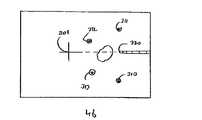
ここで図面を参照すると、本発明による装置の基本的なセットアップが図1に示される。手持ち式のツール100は、近位端110と遠位端122を有する。その遠位端は、標的150でのツールによって処置されるためにこの標的150に誘導される。追跡モジュール110は、ツールの近位端、好ましくはこの近位端のハンドルに固定状態に取り付けられる。追跡モジュールは、少なくとも適所にある、好ましくは標的150に対する方向でもあるツール120の遠位先端122の位置を示す。身体に対するツールの位置の決定は、追跡モジュールと身体の間で直接的に行われ、ツールと中間参照システムの間で中間測定を行う必要がない。追跡モジュール110の第1の好ましい実施形態において、追跡モジュールは、単一のカメラ115を含む。追跡モジュールの第2の好ましい実施形態において、追跡モジュールは、さらに第2のカメラ116を含む。これらのカメラは、標的150の一部分であり、あるいは定位置で標的150に隣接している複数の参照マーク155を画像化し、明確に識別するために使用される。同時に、カメラは、ツール120の少なくとも一部分も画像化する。
カメラ115および116は、カメラと処理システムの少なくとも一部とが共通のプロセッサーチップに実装されうるCMOSカメラなどの、自律単一チップ型のものが好ましい。この場合、チップは、典型的にはクロック発生器、タイミング発生器、行列セレクター、および/または シフトレジスター、出力ドライバー、必要に応じて露出補正機構、必要に応じて利得およびオフセット制御、ならびにビデオ信号をこの単一チップカメラに独立に生成させるために必要なその他の電子回路を含む、ビデオ信号の生成に必要なすべての電子回路を内蔵することが好ましい。ビデオという用語は、アナログ出力、デジタル出力、圧縮デジタル出力などを含む画像の流れを供給するいずれかのタイプのカメラ出力を表すために本明細書ではより広い意味で使用され、一般に考えられる連続ビデオのフレームレートでの出力を必ずしも意味しない。カメラは、周辺電子回路によって支えられるCCD技術で設計されて製造されうるが、論理セルと検出セルを同じ物理的なダイ内で結合することができるため、CMOS技術で製造されることが好ましい。カメラレンズは、単一のプラスチック成形レンズであることが好ましい。Referring now to the drawings, the basic setup of an apparatus according to the present invention is shown in FIG.Handheld tool 100 has a
Cameras 115 and 116 are preferably of autonomous single-chip type, such as CMOS cameras, where the camera and at least a portion of the processing system can be mounted on a common processor chip. In this case, the chip typically includes a clock generator, timing generator, matrix selector, and / or shift register, output driver, exposure compensation mechanism as needed, gain and offset control as needed, and video signals. It is preferable to incorporate all the electronic circuits necessary for the generation of the video signal, including other electronic circuits necessary for the single chip camera to generate them independently. The term video is used herein in a broader sense to refer to any type of camera output that provides a stream of images including analog output, digital output, compressed digital output, etc. It does not necessarily mean output at the frame rate. The camera can be designed and manufactured in CCD technology supported by peripheral electronics, but is preferably manufactured in CMOS technology because the logic and detection cells can be combined in the same physical die. The camera lens is preferably a single plastic molded lens.
追跡装置の好ましい実施形態は、図2に概略的に示される。カメラのビデオ出力信号は、フレームグラバー210に供給される。ビデオ信号の転送は、ワイヤ112を通じて行われうるが、本発明の好ましい一実施形態において、これは無線で達成される。フレームグラバー210でデジタル化されたビデオ信号は、コンピュータ200に供給され、コンピュータ200は、追跡される対象に対する追跡モジュール110の位置を決定し、ディスプレー230に表示される誘導命令を決定する。別の好ましい実施形態において、アナログ/デジタル変換器は、カメラの一部であり、コンピュータへのデータ転送は、デジタル的に行われる。コンピュータは、ノートパソコンであることが好ましい。
本発明の好ましい例示的な例で採用される数値計算との関連で、座標系が図6に示される。追跡される対象は、直交座標系(Cartesian system-of-coordinates)610を規定する。対象は、座標系620を規定するレンズによって観察される。レンズは、対象点612を画像座標系630で規定される像点632に投影している。点612は、ベクトルx=(x,y,z)によって座標系610で規定され、ベクトルk=(k,l,m)によって座標系620で規定される。この点の画像平面への投影は、ベクトル(p,q,f)である。筆者らは、対象からレンズ座標系への変換をベクトルk0=(k0,l0,m0)によって表される変換と、3×3の正規直交行列Tによって表される回転として定義する。対象とレンズ座標系の間の変換は、次の通りである。
In the context of the numerical computation employed in the preferred illustrative example of the present invention, a coordinate system is shown in FIG. The object being tracked defines a Cartesian system-of-
式(4)を使って行列の残りの値を求めるには、行列Tの4つの要素のみを決定すれば十分である。カメラの6つの自由度(位置と向き)の決定は、既知の参照マーク点を使用し、それらの対応する画像座標を測定し、式(1)〜(4)を使って変換k0と回転Tを求めることによって実行される。求められる未知数は、全部で7つある。カメラが1個しか使用されない場合、既知の対象座標系の位置を有する4つの参照マーカー612が使用されるべきである。各参照用に2つの線形独立の画像データ(piおよびqi)があるので、4つの参照マーカーがあれば十分であり、7つの未知数の場合4×2=8個の独立した式が得られる。カメラを追加した場合は、2つの異なる視点による参照マーカーの2つの画像間に位置ずれがある。これら参照マーカーのいずれの場合も、これらの位置ずれがカメラ間の位置ずれの方向に生じることを示すことは、容易である。それゆえ、参照マーカーの各々に対して新たな線形独立の測定データが1つだけあるので、合計3×3=9個の線形独立の式を有する3つの参照マーカーは、この組の式を解くには十分である。
「基準点」と呼ばれる点を備える参照マーカーは、形、色、または、きめによる視覚的に識別可能なスポットまたは曲線などのいずれかの識別可能な特徴となりうる。これらの参照マーカーは、対象のはっきり見える部分の目印でありうるか、または物理的な対象または印のような特別に追加された対象でもありうる。その他のオプションとして、能動的に照射されるマーカーが挙げられ、これは、光源、またはカメラや他の場所の近くに取り付けられた光源に由来する光を反射する反射物であってもよい。能動的に照射されるマーカーのオプションでは、ビデオの分析を簡素化してもよい場合に信号の符号化が可能になる。能動光源の場合、各マーカーは、各マーカーを明確に識別しやすくするための特殊な符号化が行われてもよい。To determine the remaining values of the matrix using equation (4), it is sufficient to determine only four elements of the matrix T. The determination of the six degrees of freedom (position and orientation) of the camera uses known reference mark points, measures their corresponding image coordinates, and transforms k0 and rotations using equations (1)-(4) This is done by determining T. There are seven unknowns required. If only one camera is used, four
A reference marker comprising points called “reference points” can be any identifiable feature such as a visually identifiable spot or curve by shape, color, or texture. These reference markers can be landmarks of a clearly visible part of the object, or can be physical objects or specially added objects such as marks. Other options include markers that are actively illuminated, which may be a light source or a reflector that reflects light from a light source mounted near a camera or other location. The actively illuminated marker option allows for signal encoding when video analysis may be simplified. In the case of an active light source, each marker may be specially coded to facilitate easy identification of each marker.
オプションとして、異なった基準点間の不明確さを回避するために、異なる形、パターン、または色を採用するなどして各組の1つまたは複数の基準点が他の基準点と見分けられるようにしてもよい。あるいは、組の基準点の向きを一意的に規定するために矢印などのマーキングが追加されてもよい。ある場合には、パッチの向きに対して装置をどの方向に保つべきかをユーザーに示し、画像処理において不明確になりかねない限界までユーザーがシステムを回転しないようにすれば十分であることが分っている。
最も好ましくは、マーカー配列は、複数の基準点を担持する身体の表面に取り付ける単一パッチとして行われる。一部の好ましい実施形態において、位置を予測する数理解析を簡素化するために、パッチは、4つの基準点1組を実質的に共通の平面内に保持するように構成される。この効果は、例えば、硬いパッチを採用したり、2つの主要方向の一方向だけに同時に屈曲しがちな限られた可撓性を有するパッチを採用したりして多くの方法で実現されてもよい。参照点の共平面性は、システムの必要条件ではなく、十分な処理能力が得られれば必要でない場合もあることに留意されたい。
本発明の好ましい一実施形態において、対象座標の参照点の位置は、例えば、治療処置のナビゲーション段階に先立って行われる較正によって既知である。較正は、機械的手段を使って実行されてもよく、またはCTデータなどの画像データに基づいて決定されてもよい。
カメラのビデオ出力における参照点の識別は、画像処理法によって決定されうる。このような方法は、当技術分野で周知であり、したがって、コンピュータ200上で実行される必要なソフトウェアコードを書き込んでビデオからの参照マーカーの座標を決定することは、当業者の通常技術の範囲内にある。Optionally, to avoid ambiguity between different reference points, each set of one or more reference points can be distinguished from other reference points, such as by employing different shapes, patterns, or colors. It may be. Alternatively, a marking such as an arrow may be added to uniquely define the orientation of the set of reference points. In some cases, it may be sufficient to indicate to the user which direction the device should be kept with respect to the patch orientation and to prevent the user from rotating the system to a limit that may be ambiguous in image processing. I know.
Most preferably, the marker array is performed as a single patch attached to the body surface carrying a plurality of reference points. In some preferred embodiments, the patch is configured to hold a set of four reference points in a substantially common plane to simplify the mathematical analysis of predicting position. This effect can be realized in many ways, for example by using a hard patch or by using a patch with limited flexibility that tends to bend in only one of the two main directions at the same time. Good. Note that the coplanarity of the reference points is not a system requirement and may not be necessary if sufficient processing power is obtained.
In a preferred embodiment of the present invention, the position of the reference point of the object coordinates is known, for example, by a calibration performed prior to the navigation phase of the therapeutic procedure. Calibration may be performed using mechanical means or may be determined based on image data such as CT data.
The identification of the reference point in the video output of the camera can be determined by image processing methods. Such methods are well known in the art, and therefore it is within the ordinary skill of a person skilled in the art to write the necessary software code to be executed on the
身体内画像用の三次元(3D)スキャナーは周知である。例えば、X線透視法、コンピュータ断層撮影法(CT)、磁気共鳴画像(MRI)、陽電子放出断層撮影法(PET)、および超音波である。また、本発明の好ましい一実施形態によると、光学的基準点を備えるための身体表面に貼付されるパッチは、標的に対するパッチ位置の登録を容易にするために非光学的画像システムによって容易に検出されるように構成された複数のマーカーを備える。典型的には、これは、使用される特別な画像技術において高コントラスト機能をもたらす適切に選定された材料の存在を要する。例えば、CTスキャナーで使用されるマーカーは、鉛の小球で作られることが好ましい。この小球は、平らなプラスチック製ディスクに埋め込まれうる。この小球が光学的基準点と既知の空間関係にあるようにパッチ内のどこかに位置決めすると、登録が十分に可能である。最も好ましくは、非光学的画像システム用のマーカーの位置は、光学的基準点と一致するので、光学的基準点は、スキャンされたデータから直接得られる。例えば、好ましい一オプションによると、前記小球の座標がスキャンされたデータとカメラの画像との両方で決定されうるようにカラーマークが小球の上に印刷される。あるいは、マーカーは、シルクスクリーン法を使ってCT(またはMRI)画像で容易に見られる適切なコントラストの染剤を印刷することによって実現される。例えば、ヨウ素を染剤に添加することは、染剤をCT画像内で容易に見えるようにするのに有効である。この後、これらのマーカーの座標は、基準点として使用されてカメラの向きとCTのボリュームデータとを登録し、CTデータで決定された標的にツールを導くことができる。共通の基準点を介して1つの座標系を別の座標系に登録する計算は、当技術分野で周知である(例えば、"Medical Image Registration by Hajnal Hill and Hawkes, CRC Press,2001"を参照されたい)。 Three-dimensional (3D) scanners for in-body images are well known. For example, fluoroscopy, computed tomography (CT), magnetic resonance imaging (MRI), positron emission tomography (PET), and ultrasound. Also according to a preferred embodiment of the present invention, a patch applied to the body surface for providing an optical reference point is easily detected by a non-optical imaging system to facilitate registration of the patch position relative to the target. A plurality of markers configured to be configured. Typically this requires the presence of a properly selected material that provides a high contrast function in the particular imaging technology used. For example, the markers used in CT scanners are preferably made of lead globules. The spheres can be embedded in a flat plastic disc. Registration is sufficiently possible if the small sphere is positioned somewhere in the patch so that it has a known spatial relationship with the optical reference point. Most preferably, the position of the marker for the non-optical imaging system coincides with the optical reference point, so that the optical reference point is obtained directly from the scanned data. For example, according to a preferred option, a color mark is printed on the sphere so that the coordinates of the sphere can be determined from both the scanned data and the camera image. Alternatively, the markers are realized by printing a suitable contrast dye that is easily seen in CT (or MRI) images using a silk screen method. For example, adding iodine to the dye is effective to make the dye easily visible in CT images. The coordinates of these markers can then be used as reference points to register the camera orientation and CT volume data and guide the tool to the target determined by the CT data. Calculations for registering one coordinate system with another through a common reference point are well known in the art (see, eg, “Medical Image Registration by Hajnal Hill and Hawkes, CRC Press, 2001”). Wanna)
基準点と標的の相対位置を決定するCTまたはMRIなどの3D画像法の代案として他の技法が使用されてもよい。非限定の一例として、標的とパッチ内のマーカーとの相対位置を決定するための2つの非平行な図がX線透視装置(これ自体は二次元画像装置)から得られる。各図において、6つの自由度のX線透視装置の位置は、基準点の光学的処理と同様の方法で、X線透視図で視覚化されたパッチ内のマーカー位置から決定され、標的位置がマークされる。2つの非平行な図の標的位置に対応する線の交点は、パッチに対する標的の位置を特定する。
ツール先端の位置と方向の算出に採用される1つのパラメーターは、身体内へのツールの穿通点である。原理上、穿通点は、ユーザーによってカメラの視野内にある身体表面の任意の位置に選定されうるものであり、この位置は、カメラ115から画像処理されることによって決定されうる。実際に、穿通点をより容易に および/または 通常は可能でないようなより高い精度で決定するためには、パッチの存在を利用することが典型的に好ましい。したがって、身体内へのツールの挿入は、パッチを通して行われることが好ましい。特に好ましい一実施において、パッチ自体は、身体内へのツール遠位端の穿通点を描くように構成される。これは、ツールが挿入される開口を事前に設けることによって実現されてもよい。このように、いったんパッチ内のマーカー位置が標的に対して登録されると、挿入点の位置が直ちに分かる。別の実施において、身体内へのツールの遠位端の穿通点は、治療処置自体の中でカメラ画像の処理によって得られてもよい。この場合、パッチは、画像処理に基づく穿通位置の算出を容易にする長方形格子などの幾何学的パターンを好都合に特徴づけてもよい。穿通位置は、穿通直前にツールの先端をこの位置と接触するようにさせて決定されてもよく、あるいはツールを前進させながら穿通後に行われる計算によって決定され、すなわち精度がより高められてもよい。
特に好ましい一手順によると、治療処置の初めに、調整ステッカー(coordinator sticker)または基準マーカーを含む材料のブロックまたは層で作られた他の「パッチ」が標的の上にある患者の皮膚に貼付される。CT(または、他のボリュームイメージング)スキャンが行われる。マーカーと標的の位置が決定され、例えば、ディスクオンキーメモリー220を介してコンピュータ200に入力される。このデータに基づいて、標的へのツールのナビゲーションが決定されうる。Other techniques may be used as an alternative to 3D imaging methods such as CT or MRI to determine the relative position of the reference point and the target. As a non-limiting example, two non-parallel views for determining the relative position of the target and the marker in the patch are obtained from a fluoroscope (which is itself a two-dimensional imager). In each figure, the position of the fluoroscope with six degrees of freedom is determined from the marker position in the patch visualized in the fluoroscopy in the same way as the optical processing of the reference point, and the target position is Marked. The intersection of the lines corresponding to the target positions in the two non-parallel figures identifies the target position relative to the patch.
One parameter employed to calculate the position and orientation of the tool tip is the penetration point of the tool into the body. In principle, the penetration point can be selected by the user at any position on the body surface within the field of view of the camera, and this position can be determined by image processing from the camera 115. In fact, it is typically preferred to utilize the presence of a patch in order to determine the penetration point more easily and / or with a higher accuracy that is not normally possible. Therefore, the insertion of the tool into the body is preferably done through the patch. In one particularly preferred implementation, the patch itself is configured to delineate the penetration point of the tool distal end into the body. This may be achieved by providing an opening in which the tool is inserted in advance. In this way, once the marker position in the patch is registered for the target, the position of the insertion point is immediately known. In another implementation, the penetration point of the distal end of the tool into the body may be obtained by processing camera images within the therapeutic procedure itself. In this case, the patch may conveniently characterize a geometric pattern such as a rectangular grid that facilitates the calculation of the penetration position based on image processing. The piercing position may be determined by bringing the tip of the tool into contact with this position immediately before piercing, or may be determined by calculations performed after piercing while the tool is advanced, i.e., the accuracy may be further increased. .
According to one particularly preferred procedure, at the beginning of the therapeutic procedure, a coordinator sticker or other “patch” made of a block or layer of material containing a reference marker is applied to the patient's skin overlying the target. The A CT (or other volume imaging) scan is performed. The positions of the marker and the target are determined and input to the
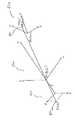
ナビゲーション中に、ツールの撓みの補償が導入されるべきである。本明細書の説明と特許請求の範囲とにおいて、ツールの無応力状態に対してある程度の曲率を生じるツールの一時的な弾性変形を表現するために「撓み」、「屈曲」、および「曲り」という用語が互換可能に使用される。以下の例では、単一カメラの追跡システムを補償する方法の好ましい例を説明する。図3aおよび図3bにおいて、撓みのないツールのシナリオが説明される。カメラモジュール110は、ツール120の少なくとも一部分が少なくとも4つのマーカー310〜313とともにカメラに写るような位置と方向でツール100の近位側に取り付けられる。ここで、カメラの座標系におけるツールの軸の形状とその長さが設計パラメーターから、あるいは較正のいずれかによって事前に知られているものと仮定される。具体的に、ツールの長さに関しては、ツールの遠位先端をパッチ表面の任意の点に接触させ、システムを駆動してカメラとパッチ間の距離を決定することによって、治療処置の初めに好都合に決定されてもよい。パッチ自体は、滅菌されているので、治療処置を行う点において問題を生じることはない。他の較正パラメーターは、以下で議論されるように、カメラに事前に格納されるか、またはデータ記憶媒体に備えられることが好ましい。調整パッチ(coordinator patch)に対する画像モジュール110の位置と向きが決定される。ツールの遠位先端122の位置は、その軸322に沿った軌跡によって決定されうる。画像の上に表示される先端は、破線322と十字形301で示されるようにカメラから出力される。撓みがない場合、先端の動きは、カメラの動きと同じである。図4aと図4bに示されるように、ツールが撓むと、撓みが補償されなければ、誤差が生じる。ツールの軌跡は、カメラに対して決定され、かつカメラは、その向きがツールの近位端の撓みによって変わるので、確定されたツール322の軸は、ツールの遠位部の実際の軸と、もはや一致しない。その結果、ツールの先端(または、標的の平面内にあるニードルの軌跡のように、ニードルの方向に沿ったいずれかの他の位置)を表わす十字形301は、ディスプレー上の間違った位置に表示される。この状態が補正されなければ、特に比較的可撓性のあるニードルでは、目標とされる標的を外すようなナビゲーションの失敗をしばしば招くこともある。
ツールの屈曲を補正するために多くのモデルが使用されてもよい。非限定の一例として、補正は、ツールが身体内に入る点320が調整パッチの平面300内にあるとの仮定に基づいて決定されてもよい。式(1)〜(4)を解くことによって、平面300の位置と向きのパラメーターが分かる。身体内のツールの経路、その先端位置、および標的平面内のその交点は、図5aおよび図5bに示されるように、前記の接線方向の軌跡として決定される。During navigation, tool deflection compensation should be introduced. In the description and claims herein, “deflection”, “bending”, and “bending” to describe a temporary elastic deformation of the tool that produces some degree of curvature with respect to the unstressed state of the tool. The term is used interchangeably. The following example describes a preferred example of a method for compensating a single camera tracking system. In FIGS. 3a and 3b, a scenario of a tool without deflection is illustrated. The
Many models may be used to compensate for tool bending. As a non-limiting example, the correction may be determined based on the assumption that the
実際の穿通位置、理論上の撓みのない入口点、まだ身体外にあるツールの長さ、およびその他のいずれかの測定済みパラメーターの任意の組合せに基づいてツールの撓みを算出するために、したがって、遠位先端の指示方向を導出するために、様々な異なったモデルが使用されてもよいことに留意されたい。実際に、遠位先端の補正された指示方向に関する特に簡単な計算は、広範な実施にきわめて有効であることが分っている。以下、この計算は、図11を参照して説明される。
具体的に、本明細書に示す場合において、ツールは、パッチの領域内の既知の位置320で身体内に穿通する。理論上は屈曲のないツールの経路は、破線322で表されるが、カメラの光軸は、破線324で表される。これらの軸は、典型的にほぼ平行であり、システムとともに提供される較正データによって規定される。撓みベクトル326は、屈曲のないツール経路322から光軸324に垂直な平面内にある穿通点320までのベクトルとして規定される。身体内におけるツールの補正された方向を計算するために、撓みベクトル326のスケーリング値(scaled value)に対応する補正ベクトル328で現在のツールハンドルの位置を反対方向に補正することによって、補正された理論上のツール位置を実現する。スケーリングファクターは、定数であってもよく、例えば、身体外のツールの長さの関数などの可変パラメーターであってもよい。ツール先端の推定された指示方向は、この場合、補正された理論上のツール位置から実際の挿入点を通過するライン330となるように選ばれる。To calculate the deflection of the tool based on any combination of the actual penetration position, the theoretically free entry point, the length of the tool still outside the body, and any other measured parameters Note that a variety of different models may be used to derive the pointing direction of the distal tip. Indeed, a particularly simple calculation regarding the corrected pointing direction of the distal tip has been found to be very effective for a wide range of implementations. Hereinafter, this calculation will be described with reference to FIG.
Specifically, in the case shown herein, the tool penetrates into the body at a known
典型的には、補正ベクトル328に対して1〜3の範囲にある一定のスケーリングファクターが有効であることが分っている。補正が完全な補正であることは、一般に決定的な意味を持たないことが分っている。事実上は、ある場合には、撓みを完全に補正しようとすると、ユーザーによる過補償 および/または 何らかの位置測定誤差の増加がもたらされることがある。様々な実際的な実施において、約1.5のスケーリングファクターを使用してきわめて有効な結果が得られている。
2個のカメラを備える追跡システムにおけるツールの撓みの補償は、よく似ており、撓んだツールの弧は、ステレオペア画像から直接決定される可能性があり、式(3)を用いてツールに沿ったいくつかの点の位置決定が簡素化される。
本発明の別の好ましい実施形態において、調整パッチは、可撓性材料から作られたステッカーとして実現され、ステッカーの片側は、患者の皮膚に貼付されるように接着剤で覆われている。ナイロンまたはポリ塩化ビニール(PVC)などのポリマーであることが好ましい可撓性材料は、可撓性材料に埋め込まれた小さい参照マーカーを有する。前述したように、これらのマーカーは、登録に使用される非光学的画像技法の下で高コントラストを提供する材料を使って実現されることが好ましい。CTの場合、これらのマーカーは、X線を通さず、例えば、典型的に1〜2mmの直径を有する鉛の小球で作られる。さらに、「印」などの光学基準点は、ステッカーの表面に印刷される。これらの印は、線、円、またはその他の形、すなわち、光学的に明確な特徴でありうる。これらは、単一色で印刷されうるか、さらに好ましくは、色区分による区別が容易な多色で印刷されうる。総じて、印は、ツールを標的にナビゲートするために使用される座標系を規定する。埋め込まれたマーカーは、ツールの位置をCTボリュームに登録するために使用される。印は、埋め込まれたマークの位置がカメラの画像から決定されるように配置される。It has been found that a constant scaling factor, typically in the range of 1-3, is valid for the
Compensation of tool deflection in a tracking system with two cameras is very similar, and the arc of the deflected tool may be determined directly from the stereo pair image and can be determined using equation (3) The location of some points along is simplified.
In another preferred embodiment of the present invention, the conditioning patch is implemented as a sticker made from a flexible material, and one side of the sticker is covered with an adhesive so as to be applied to the patient's skin. A flexible material, preferably a polymer such as nylon or polyvinyl chloride (PVC), has a small reference marker embedded in the flexible material. As previously mentioned, these markers are preferably realized using materials that provide high contrast under the non-optical imaging techniques used for registration. In the case of CT, these markers do not pass X-rays and are made, for example, of lead globules typically having a diameter of 1-2 mm. Furthermore, optical reference points such as “marks” are printed on the surface of the sticker. These indicia can be lines, circles or other shapes, i.e. optically distinct features. These can be printed in a single color, or more preferably in multiple colors that can be easily distinguished by color classification. Overall, the indicia define the coordinate system used to navigate the tool to the target. The embedded marker is used to register the tool position in the CT volume. The mark is arranged so that the position of the embedded mark is determined from the image of the camera.
追跡装置の光学系によって見られる領域のサイズは、その視野(FOV)とレンズからのステッカーの距離との関数である。カメラとステッカー間の距離が大きくなるにつれて、光学系がカバーする領域も大きくなる。システムの精度を維持するためには、基準点の間隔をできる限り開けることが好ましい。ツールを身体内に挿入する間に、カメラはステッカーに次第に近づくため、カメラのFOVがカバーする領域は次第に小さくなる。最も好ましくは、初期の位置決めと最終段階の穿通の両方に対する基準点の分布を最適にするために、光学的に明確な特徴によって指定される2つ以上の組の基準点が異なる間隔で、すなわち、ある組は、より小さい領域をカバーするようにより近い間隔で、また他の組は、より大きい領域に広がるようにさらに大きい間隔で配置される。
別の光学的特徴によると、パッチ上の一部の位置は、特定のシステム機能に関連する制御位置に指定されてもよい。システムは、次に、システムオペレーターがツールの先端を制御位置の1つと接触(または、最接近)させているかどうかをモニターし、接触(または、最接近)させていれば、割り当てられた対応するシステム機能を実行する。このようにして、パッチ上の位置に割り当てられてもよいシステム制御機能の例は、ツール長さ再較正の開始、ディスプレーの表示モードまたは他のパラメーターの変更、他のリアルタイムデータの入力またはシステムのいずれかの他の操作パラメーターの変更、および電源オフを含むが、これらに限定されない。ユーザーインタフェース入力として、パッチ上の位置へのツールの接触を使用することは、システムオペレーターが滅菌されていないコンピュータ機器に触れたり、治療処置の実施現場付近から注意をそらしたりする必要を避けるため、本発明に照らして特に好都合である。The size of the area seen by the tracking system optics is a function of its field of view (FOV) and the distance of the sticker from the lens. As the distance between the camera and the sticker increases, the area covered by the optical system also increases. In order to maintain the accuracy of the system, it is preferable to increase the distance between the reference points as much as possible. While the tool is inserted into the body, the camera gradually approaches the sticker, so that the area covered by the camera FOV becomes progressively smaller. Most preferably, in order to optimize the distribution of reference points for both initial positioning and final penetration, two or more sets of reference points specified by optically distinct features are at different intervals, i.e. Some sets are placed closer together to cover a smaller area, and other sets are arranged more evenly to cover a larger area.
According to another optical feature, some positions on the patch may be assigned to control positions associated with a particular system function. The system then monitors whether the system operator is touching (or closest) the tool tip to one of the control positions, and if it is touching (or closest), the corresponding assigned Perform system functions. In this way, examples of system control functions that may be assigned to locations on the patch include initiating tool length recalibration, changing display display mode or other parameters, entering other real-time data or system Including, but not limited to, changing any other operating parameters and powering off. Using the tool's contact to the location on the patch as user interface input avoids the need for the system operator to touch non-sterile computer equipment or divert attention from near the site of the treatment procedure, Particularly advantageous in light of the present invention.
システムは、ニードル、ポインターなどの細長いツールを導くために使用されてもよい。ツールは、剛性または半可撓性であってもよい。これに関連して、「剛性」という用語は、標的へのツールの誘導精度に著しい影響を与える程度まで通常の使用状態で屈曲しないツールを表すために使用される。これに関連して、「半可撓性」という用語は、通常の使用状態で、際立った形状の変化なしで撓むツールを表すために使用される。数値的には、「半可撓性」という用語は、通常の使用においてツールの長さの2倍よりも大きい、そして典型的にはツールの長さの少なくとも3倍の、屈曲に起因する曲率半径を維持するいずれかの細長いツールを表すために使用されてもよい。
本発明の一実施形態において、ツールの形状は、事前に分かる。別の実施形態において、ツールの形状は、画像による治療処置の間に決定される。前述の実施形態では、ツールの遠位部は、一部分に隠れているが、本発明は、遠位部がすべての操作において見える場合の用途にも適用可能である。このような実施形態において、ツールの遠位先端の位置は、ビデオ画像から直接随意的に決定される。The system may be used to guide elongated tools such as needles, pointers and the like. The tool may berigid or semi-flexible. In this context, the term “rigidity ” is used to describe a tool that does not bend in normal use to the extent that it significantly affects the accuracy with which the tool is directed to the target. In this context, the term “semi-flexible” is used to describe a tool that flexes without noticeable shape change under normal use conditions. Numerically, the term “semi-flexible” is a curvature due to bending that is greater than twice the length of the tool in normal use and typically at least three times the length of the tool. It may be used to represent any elongated tool that maintains a radius.
In one embodiment of the invention, the shape of the tool is known in advance. In another embodiment, the shape of the tool is determined during the therapeutic treatment by image. In the previous embodiment, the distal portion of the tool is hidden in part, but the invention is also applicable to applications where the distal portion is visible in all operations. In such embodiments, the position of the distal tip of the tool is optionally determined directly from the video image.
本発明の好ましい一実施形態において、画像は、コンピュータ画面に表示される。本発明の別の実施形態において、奥行き知覚を与える三次元表示を可能にするためにゴーグルが使用される。いくつかの実施形態において、身体の仮想3D画像は、身体に対するツールの位置と角度に基づいて、3Dスキャンデータとコンピュータディスプレー上の表示から生成されて身体内臓器内部のツールの経路を示すことができる。
先に述べたように、ディスプレーの内容は、標的の位置の表現と、標的を含み指示方向に実質的に垂直な平面上に投影される遠位端の指示方向に沿った現在の先端の投影とを含むことが好ましい。投影に使用される平面は、標的を含みカメラの光軸に垂直な平面であっても実際にはよいが、撓みが典型的には比較的小さいため、このような投影平面は、いずれも「指示方向に実質的に垂直な」という用語の範囲内にあるものと考えられる。
標的の位置と現在の先端の投影に加えて、標的へのツールのナビゲーションを容易にするために、ディスプレーにはほかにも様々な項目が示されることが好ましい。第1の特に好ましいオプションによると、標的の位置と現在の先端の投影のグラフィック表現は、カメラから得られた画像に対するオーバーレイとして表示される。これは、ユーザーが自己の空間定位の維持に役立つために非常に有用であることが分っている。オプションとして、画像内の対応する基準点が正常に追跡されていることを示す各基準点に関連して可視指示が表示されてもよい。オプションとして表示されてもよい他の項目として、mm単位の数値距離、および現在の先端位置の表現など、遠位端から標的までの距離の表示が挙げられる。In a preferred embodiment of the present invention, the image is displayed on a computer screen. In another embodiment of the invention, goggles are used to enable a three-dimensional display that provides depth perception. In some embodiments, a virtual 3D image of the body may be generated from 3D scan data and a display on a computer display based on the position and angle of the tool relative to the body to show the path of the tool within the body organ. it can.
As previously mentioned, the display content is a representation of the target position and the projection of the current tip along the indicated direction of the distal end projected onto a plane that includes the target and is substantially perpendicular to the indicated direction. Are preferably included. The plane used for projection may actually be a plane that includes the target and is perpendicular to the optical axis of the camera, but since such deflection is typically relatively small, all such projection planes are “ It is considered to be within the scope of the term “substantially perpendicular to the pointing direction”.
In addition to target position and current tip projection, various other items are preferably shown on the display to facilitate navigation of the tool to the target. According to a first particularly preferred option, the graphical representation of the target position and the current tip projection is displayed as an overlay to the image obtained from the camera. This has been found to be very useful to help users maintain their spatial orientation. Optionally, a visual indication may be displayed in association with each reference point indicating that the corresponding reference point in the image has been successfully tracked. Other items that may optionally be displayed include a numerical distance in mm and a display of the distance from the distal end to the target, such as a representation of the current tip position.
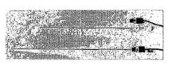
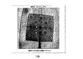
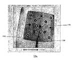
選択された標的に針をナビゲートする過程の例が図7〜図10に示される。空のプラスチック製ボックスが身体として使用され、標的はその底面に接着され、調整ステッカーは、そのカバーに貼付される。まず、身体(ボックス)がCTスキャナーによってスキャンされる。スキャンされたデータは、コンピュータプログラムに供給される。このプログラムを使って、基準点の位置(図7a)と標的の位置(図7b)がマークされる。図8に例が示されるように、小型カメラが簡単なアダプターによって針に取り付けられる。多くの場合、使用されるカメラのレンズは、図9aに見られるように画像をゆがめており、図9bに示されるように補正される必要がある。図10a〜図10dは、システムのナビゲーション画面を示す。情報は、カメラの原画像1300の上方に表示される。調整ステッカー1330は、8つの印刷されたマーカー、4つの緑色マーカー1310、および4つの青色マーカー1314を含む。原色を使用すると、画像処理中にマーカーの識別が容易になり、少なくとも医学的応用の場合、視野内の血液の存在に起因する混乱を避けるために赤色は使用しないことが好ましい。前述のように、他の種類の光学的に明確なマーキングは使用してもよい。青色マーカーは、緑色マーカーが広がる比較的広範な領域内に比較的狭い間隔で配置される。所定の孔1320には調整ステッカーを通して入る針のシャフト1120が示される。図10aでは針が屈曲しておらず、したがって、その軸1322は、針のシャフト1120と一致する。標的1302は、標的面において測定された直径が10mmのディスクを表示するように較正された青色の外側リングと、直径5mmのディスクの緑色の内側ディスクとの、いずれも標的に中心がある2つの着色された同心ディスクによって示される。また、針の先端と標的との間の距離は、テキストボックス1332内に表示される。An example of the process of navigating aneedle to a selected target is shown in FIGS. An empty plastic box is used as the body, the target is glued to the bottom surface, and the adjustment sticker is affixed to the cover. First, the body (box) is scanned by a CT scanner. The scanned data is supplied to a computer program. Using this program, the position of the reference point (FIG. 7a) and the position of the target (FIG. 7b) are marked. As an example is shown in FIG. 8, a small camera is attached to theneedle by a simple adapter. In many cases, the lens of the camera used distorts the image as seen in FIG. 9a and needs to be corrected as shown in FIG. 9b. 10a to 10d show the navigation screen of the system. The information is displayed above the
図10bに示されるように、標的の1つに針の照準を合わせると、この標的が自動的に選択され、この選択は、緑色から黄色への変化によって示される。誘導中に、システムは、針のシャフトの撓みを測定する。図10cは、シャフト1120が撓んでいる場合を示す。この撓みがあるため、針1322の予測される経路(破線で示される)は、シャフトの画像と一致しない。十字レチクル1301は、距離に依存したサイズで表示され、それによって、奥行き感を与えることが好ましく、すなわち、先端から標的間の距離が減少するとレチクルのサイズが増加する(逆の場合も同様である)。ニードルを身体内に押し込むと、カメラと調整ステッカー間の距離が減少し、視野によってカバーされるステッカーの領域が減少する。その結果、図10dに見られるように、緑色のマーカーがカメラ視野の外側で消えて、ツールを誘導する青色マーカーのみが残る。針の先端が標的の平面に達すると、十字レチクルが星形レチクル(図10dの1341)に変化して、それ以上の前進が不要であることを通告する。
針の撓みを推測する際、典型的には、実際の入口点と理論上は撓みのない入口点との差の計算に基づく同様の概念的アプローチによって前述の光学追跡装置以外の追跡技術も使用されてもよい。このような技術は、ツールの近位端に位置センサーと、身体内へのツールの実際の入口点に隣接した別の位置センサーとを埋め込むことを含むが、これらに限定されない。もう1つの方法は、身体外の針のシャフトに沿ってマークされた座標をスキャンし、さらに、その座標から身体内の経路を予測することによって身体外の撓みを予測することである。このようなスキャニング過程は、光学式立体スキャナーなどのスキャナーによって実行されてもよい。
身体内の針の経路を予測する際、CTデータは、予測経路に沿った組織の可撓性と密度など、一部の組織の機械的パラメーターを評価し、このパラメーターを使って針の撓みを予測するために使用されてもよい。As shown in FIG. 10b, when theneedle is aimed at one of the targets, this target is automatically selected, and this selection is indicated by a change from green to yellow. During guidance, the system measures the deflection of theneedle shaft. FIG. 10c shows the case where the
When estimatingneedle deflection, tracking techniques other than the optical tracking device described above are typically used with a similar conceptual approach based on calculating the difference between the actual entry point and the theoretically no entry point. May be. Such techniques include, but are not limited to, implanting a position sensor at the proximal end of the tool and another position sensor adjacent to the actual entry point of the tool into the body. Another method is to predict the deflection outside the body by scanning the marked coordinates alongthe shaft of theneedle outside the body and then predicting the path within the body from the coordinates. Such a scanning process may be performed by a scanner such as an optical stereoscopic scanner.
When predicting the path of aneedle in the body, CT data evaluates some tissue mechanical parameters, such as tissue flexibility and density along the predicted path, and uses this parameter to determineneedle deflection. It may be used to predict.
近年、インターベンション処置用のCTX線透視法が開発された。これらのスキャナーでは、単一スライスの画像が連続的に生成されて、これをリアルタイムX線透視画像装置と同様に使用することができる。本発明のシステムは、標的にツールを誘導する際にCTX線透視法に比べていくつかの利点を有する。まず、本発明のシステムは、危険なX線照射を使わずにリアルタイムでツールの連続ナビゲーションが可能である。さらに、本発明のシステムは、医師が単一CTスライスで全経路をたどらざるを得ないCTX線透視法の使用とは反対に、ツールを任意の方向、例えば、CTスライスに対して垂直にもナビゲートすることができる。 Recently, CTX fluoroscopy has been developed for interventional procedures. In these scanners, single slice images are generated continuously and can be used in the same manner as real-time fluoroscopic imaging devices. The system of the present invention has several advantages over CTX fluoroscopy in guiding the tool to the target. First, the system of the present invention enables continuous navigation of tools in real time without using dangerous x-ray exposure. Furthermore, the system of the present invention allows the tool to be moved in any direction, eg perpendicular to the CT slice, as opposed to using CTX fluoroscopy, which requires the physician to follow the entire path with a single CT slice. Can navigate.
本システムおよび本方法では、患者の身体のいずれかの必要とされる側面からツールをナビゲートすることができ、方向とは無関係であって、いずれかの特別な治療処置にとって好都合と考えられる場合は、身体の下から上向きにナビゲートすることさえできる。
カメラのレンズのゆがみは、当技術分野で周知のように多項式によって補正されることが好ましい。各レンズは、単独に補正されるべき個々のひずみを有する。本発明の好ましい実施形態において、これらの多項式は、カメラの一部分として組み立てられており、すなわち、カメラとともに提供されるデータ記憶媒体上で別途提供されるメモリーに格納される。また、これらの補正は、付属ブラケットなどの製造誤差に起因する、ツールと相対的なカメラ配列のいずれかの変動に対する目盛修正を含むことが好ましい。カメラがシステムに接続されると、多項式が読み取られてアルゴリズムに与えられ、カメラの画像がこれらの多項式によって個別に補正される。
上記の説明は、例としての機能を果たすものにすぎず、添付の特許請求の範囲で規定された本発明の範囲内で他にも多くの実施形態が考えられることは、理解されよう。The system and method allow the tool to be navigated from any required aspect of the patient's body, independent of direction, and considered convenient for any special therapeutic procedure Can even navigate upward from below the body.
Camera lens distortion is preferably corrected by a polynomial as is well known in the art. Each lens has an individual distortion to be corrected independently. In a preferred embodiment of the invention, these polynomials are assembled as part of the camera, i.e. stored in a separately provided memory on a data storage medium provided with the camera. Also, these corrections preferably include a scale correction for any variation in camera alignment relative to the tool due to manufacturing errors such as accessory brackets. When the camera is connected to the system, polynomials are read and provided to the algorithm, and the camera image is individually corrected by these polynomials.
It will be appreciated that the above description serves by way of example only and that many other embodiments are possible within the scope of the invention as defined by the appended claims.
100 ハンドヘルドツール、110 近位端(追跡モジュール、カメラモジュール、画像モジュール)、112 ワイヤ、115 カメラ、116 第2のカメラ(カメラ)、120 ツール、122 遠位端(遠位先端)、150 標的、155 複数の参照マーク、200 コンピュータ、210 フレームグラバー、220 ディスクオンキーメモリー、230 ディスプレー、300 調整パッチの平面、301 十字形、310〜313 マーカー、320 点(既知の位置、穿通点)、322 軸(破線、ツール経路)、324 光軸、326 撓みベクトル、328 補正ベクトル、330 ライン、1120 ニードルシャフト、1300 カメラの原画像、1301 十字レチクル、1302 標的、1310 マーカー、1314 青色マーカー、1320 孔、1322 軸(ニードル)、1330 調整ステッカー、1332 テキストボックス、1341 星形レチクル。100 handheld tool, 110 proximal end (tracking module, camera module, image module), 112 wire, 115 camera, 116 second camera (camera), 120 tool, 122 distal end (distal tip), 150 target, 155 Multiple reference marks, 200 computers, 210 frame grabber, 220 disc on key memory, 230 display, 300 adjustment patch plane, 301 cross, 310-313 marker, 320 points (known position, penetration point), 322 axis ( (Dashed line, tool path), 324 optical axis, 326 deflection vector, 328 correction vector, 330 lines, 1120 needle shaft, 1300 original image of camera, 1301 cross reticle, 1302 target, 1310 marker, 1314 blue Manufacturers, 1320 holes, 1322 axis (needle), 1330 Adjustment sticker, 1332 text box, 1341 star-shaped reticle.
Claims (13)
Translated fromJapanese(a)身体の内部に挿入する遠位端と、前記身体の外部で手動操作する近位部とを有する剛性または半可撓性のツールと、
(b)前記身体内への針の挿入点において前記身体の外表面に適用されるように構成され、複数の基準点を定義している光学的に検出可能な特徴によってマーカー配列を担持するパッチと、
(c)画像を生成するカメラと、
(d)(i)カメラが、前記針の前記近位部とともに移動し、(ii)前記カメラが、前記パッチが前記身体の外面に配される際に前記パッチの少なくとも一部と、前記身体内に挿入される際に前記針の遠位端を含む視野を有して向けられるように、前記針の近位部に前記カメラを取り付ける機械的リンク機構と、
(e)前記カメラとデータ通信し、前記基準点に対して前記針の少なくとも一部の位置を決定するために前記カメラの画像を処理するように構成された処理システムと、
を備える、システム。A system for measuring the position of ahand-held needle relative to the body with at least five degrees of freedom,
(A) arigid or semi-flexible tool having a distal end for insertion into the body and a proximal portion manually manipulated outside the body;
(B)a patch configured to be applied to the outer surface of the body at the point of insertion of the needle into the body and carrying a marker array with optically detectable features defining a plurality of reference points When,
(C ) a camera for generating an image;
(D )(i) the camera moves with the proximal portion of the needle, and (ii) the camera moves at least a portion of the patch when the patch is placed on the outer surface of the body, and the body as directed has a field of view including the distal end of the needle when it is inserted withina mechanical linkage for attaching the camerato the proximal portion of theneedle,
(E) a processing system in data communication with the camera and configured to process an image of the camera to determine a position of at least a portion of theneedlerelative to thereference point ;
A system comprising:
(a)前記皮膚に一時的に貼付する下面と、
(b)1組の少なくとも4つの光学的に検出可能な基準点が備えられた上面と、
(c)非光学的画像システムを使って前記パッチの位置確認を容易にする非光学的画像システムの動作の下で高コントラスト点を備えるように構成された複数のコントラスト生成機能と、
(d)前記身体の内部への前記針の前記遠位端の穿通点を示すように構成された挿入形態を備えてなるパッチ。A patch for use with the system of claim 1, comprising:
(A) a lower surface temporarily affixed to the skin;
(B) a top surface provided with a set of at least four optically detectable reference points;
(C) a plurality of contrast generation functions configured to provide a high contrast point under operation of the non-optical imaging system to facilitate localization of the patch using a non-optical imaging system;
(D) A patchcomprising an insertion configuration configured toindicate a penetration point of the distal end of theneedle into the body.
Applications Claiming Priority (4)
| Application Number | Priority Date | Filing Date | Title |
|---|---|---|---|
| US78714906P | 2006-03-30 | 2006-03-30 | |
| US85240306P | 2006-10-18 | 2006-10-18 | |
| US88760507P | 2007-02-01 | 2007-02-01 | |
| PCT/IL2007/000416WO2007113815A2 (en) | 2006-03-30 | 2007-03-29 | System and method for optical position measurement and guidance of a rigid or semi flexible tool to a target |
Publications (3)
| Publication Number | Publication Date |
|---|---|
| JP2010522573A JP2010522573A (en) | 2010-07-08 |
| JP2010522573A5 JP2010522573A5 (en) | 2012-10-11 |
| JP5146692B2true JP5146692B2 (en) | 2013-02-20 |
Family
ID=38564066
Family Applications (1)
| Application Number | Title | Priority Date | Filing Date |
|---|---|---|---|
| JP2009502331AActiveJP5146692B2 (en) | 2006-03-30 | 2007-03-29 | System for optical localization and guidance of a rigid or semi-flexible needle to a target |
Country Status (7)
| Country | Link |
|---|---|
| US (1) | US7876942B2 (en) |
| EP (2) | EP2008244B1 (en) |
| JP (1) | JP5146692B2 (en) |
| KR (1) | KR20090004899A (en) |
| CN (1) | CN101536013B (en) |
| BR (1) | BRPI0709421A2 (en) |
| WO (1) | WO2007113815A2 (en) |
Families Citing this family (121)
| Publication number | Priority date | Publication date | Assignee | Title |
|---|---|---|---|---|
| JP4719225B2 (en) | 2004-12-13 | 2011-07-06 | ジャイラス エーシーエムアイ インク | Endoscope gripping part, endoscope and manufacturing method thereof |
| WO2006078902A2 (en)* | 2005-01-19 | 2006-07-27 | Dermaspect, Llc | Devices and methods for identifying and monitoring changes of a suspect area on a patient |
| US8560047B2 (en) | 2006-06-16 | 2013-10-15 | Board Of Regents Of The University Of Nebraska | Method and apparatus for computer aided surgery |
| US7728868B2 (en) | 2006-08-02 | 2010-06-01 | Inneroptic Technology, Inc. | System and method of providing real-time dynamic imagery of a medical procedure site using multiple modalities |
| DE102008018930A1 (en)* | 2007-04-17 | 2008-11-20 | C2Cure Inc., Wilmington | Electronic component for use in imaging system i.e. camera system, for surgical instrument, has integrated circuit fastened to front side of substrate and electrically connected with continuous lines at front side |
| JP5416900B2 (en)* | 2007-11-22 | 2014-02-12 | 株式会社東芝 | Ultrasonic diagnostic apparatus and puncture support control program |
| WO2009094646A2 (en) | 2008-01-24 | 2009-07-30 | The University Of North Carolina At Chapel Hill | Methods, systems, and computer readable media for image guided ablation |
| US8340379B2 (en) | 2008-03-07 | 2012-12-25 | Inneroptic Technology, Inc. | Systems and methods for displaying guidance data based on updated deformable imaging data |
| US8363259B2 (en)* | 2008-05-24 | 2013-01-29 | Activiews Ltd. | Method for producing printed patches for optical and high-contrast guidance |
| US20090312629A1 (en)* | 2008-06-13 | 2009-12-17 | Inneroptic Technology Inc. | Correction of relative tracking errors based on a fiducial |
| ES2608820T3 (en)* | 2008-08-15 | 2017-04-17 | Stryker European Holdings I, Llc | System and method of visualization of the inside of a body |
| US8588892B2 (en) | 2008-12-02 | 2013-11-19 | Avenir Medical Inc. | Method and system for aligning a prosthesis during surgery using active sensors |
| US8374723B2 (en)* | 2008-12-31 | 2013-02-12 | Intuitive Surgical Operations, Inc. | Obtaining force information in a minimally invasive surgical procedure |
| US8611985B2 (en) | 2009-01-29 | 2013-12-17 | Imactis | Method and device for navigation of a surgical tool |
| US8641621B2 (en) | 2009-02-17 | 2014-02-04 | Inneroptic Technology, Inc. | Systems, methods, apparatuses, and computer-readable media for image management in image-guided medical procedures |
| US8554307B2 (en) | 2010-04-12 | 2013-10-08 | Inneroptic Technology, Inc. | Image annotation in image-guided medical procedures |
| US8690776B2 (en) | 2009-02-17 | 2014-04-08 | Inneroptic Technology, Inc. | Systems, methods, apparatuses, and computer-readable media for image guided surgery |
| US11464578B2 (en) | 2009-02-17 | 2022-10-11 | Inneroptic Technology, Inc. | Systems, methods, apparatuses, and computer-readable media for image management in image-guided medical procedures |
| EP2467080B1 (en)* | 2009-08-20 | 2018-04-04 | Brainlab AG | Integrated surgical device combining instrument, tracking system and navigation system |
| CN102598088A (en) | 2009-11-11 | 2012-07-18 | 艾克提维尤斯有限公司 | Systems & methods for planning and performing percutaneous needle procedures |
| WO2011063266A2 (en)* | 2009-11-19 | 2011-05-26 | The Johns Hopkins University | Low-cost image-guided navigation and intervention systems using cooperative sets of local sensors |
| US8435033B2 (en) | 2010-07-19 | 2013-05-07 | Rainbow Medical Ltd. | Dental navigation techniques |
| US20120071757A1 (en)* | 2010-09-17 | 2012-03-22 | University Of British Columbia | Ultrasound Registration |
| US8657809B2 (en) | 2010-09-29 | 2014-02-25 | Stryker Leibinger Gmbh & Co., Kg | Surgical navigation system |
| KR20130129246A (en)* | 2010-12-17 | 2013-11-27 | 아브니르 메디컬 아이엔씨. | Method and system for aligning a prosthesis during surgery |
| US9538982B2 (en)* | 2010-12-18 | 2017-01-10 | Massachusetts Institute Of Technology | User interface for ultrasound scanning system |
| DE102011012460A1 (en)* | 2011-02-25 | 2012-08-30 | Hicat Gmbh | Surgical instrument with integrated navigation control |
| US9572539B2 (en) | 2011-04-08 | 2017-02-21 | Imactis | Device and method for determining the position of an instrument in relation to medical images |
| DE102011007796B4 (en)* | 2011-04-20 | 2019-07-04 | Siemens Healthcare Gmbh | Method for determining a target position for a medical procedure |
| WO2012159123A2 (en)* | 2011-05-19 | 2012-11-22 | Alec Rivers | Automatically guided tools |
| CN103764061B (en)* | 2011-06-27 | 2017-03-08 | 内布拉斯加大学评议会 | On Tool Tracking System and Computer Assisted Surgery Method |
| US9498231B2 (en) | 2011-06-27 | 2016-11-22 | Board Of Regents Of The University Of Nebraska | On-board tool tracking system and methods of computer assisted surgery |
| US11911117B2 (en) | 2011-06-27 | 2024-02-27 | Board Of Regents Of The University Of Nebraska | On-board tool tracking system and methods of computer assisted surgery |
| US9707043B2 (en) | 2011-09-02 | 2017-07-18 | Stryker Corporation | Surgical instrument including housing, a cutting accessory that extends from the housing and actuators that establish the position of the cutting accessory relative to the housing |
| US9387008B2 (en) | 2011-09-08 | 2016-07-12 | Stryker European Holdings I, Llc | Axial surgical trajectory guide, and method of guiding a medical device |
| JP5750361B2 (en)* | 2011-11-11 | 2015-07-22 | 日本電信電話株式会社 | Work position guidance device and guidance method thereof |
| US8670816B2 (en) | 2012-01-30 | 2014-03-11 | Inneroptic Technology, Inc. | Multiple medical device guidance |
| US9314188B2 (en) | 2012-04-12 | 2016-04-19 | Intellijoint Surgical Inc. | Computer-assisted joint replacement surgery and navigation systems |
| US9439627B2 (en)* | 2012-05-22 | 2016-09-13 | Covidien Lp | Planning system and navigation system for an ablation procedure |
| US8750568B2 (en) | 2012-05-22 | 2014-06-10 | Covidien Lp | System and method for conformal ablation planning |
| US9439622B2 (en)* | 2012-05-22 | 2016-09-13 | Covidien Lp | Surgical navigation system |
| US9498182B2 (en)* | 2012-05-22 | 2016-11-22 | Covidien Lp | Systems and methods for planning and navigation |
| US9439623B2 (en)* | 2012-05-22 | 2016-09-13 | Covidien Lp | Surgical planning system and navigation system |
| DE102012209450B4 (en) | 2012-06-05 | 2019-05-29 | Siemens Healthcare Gmbh | Determining the position of a medical instrument |
| DE102012209448B4 (en) | 2012-06-05 | 2019-06-19 | Siemens Healthcare Gmbh | Determining a position of a medical instrument |
| CN104272349B (en)* | 2012-06-20 | 2018-03-02 | 皇家飞利浦有限公司 | Multiphase machine equipment tracks |
| CN104507408B (en) | 2012-06-22 | 2017-06-20 | 柯惠有限合伙公司 | For the microwave thermometric of microwave ablation system |
| CN104394764B (en) | 2012-06-28 | 2018-01-05 | 皇家飞利浦有限公司 | The private subscribers interface intervened between tissue for MR guiding |
| US20140000516A1 (en)* | 2012-06-29 | 2014-01-02 | Toyota Motor Engineering & Manufacturing North America, Inc. | Digital point marking transfer |
| AU2013286807A1 (en)* | 2012-07-03 | 2015-01-29 | The State Of Queensland Acting Through Its Department Of Health | Movement correction for medical imaging |
| EP2928406B1 (en)* | 2012-12-07 | 2019-02-20 | University of Houston System | Surgical procedure management systems |
| US9192445B2 (en)* | 2012-12-13 | 2015-11-24 | Mako Surgical Corp. | Registration and navigation using a three-dimensional tracking sensor |
| CN103040525B (en)* | 2012-12-27 | 2016-08-03 | 深圳先进技术研究院 | A kind of multimode medical image operation piloting method and system |
| WO2014110069A1 (en)* | 2013-01-11 | 2014-07-17 | The Cleveland Clinic Foundation | Alignment of manipulable sensor assembly |
| EP4309613B1 (en) | 2013-01-16 | 2025-07-23 | Stryker Corporation | Navigation systems for indicating line-of-sight errors |
| US9993273B2 (en) | 2013-01-16 | 2018-06-12 | Mako Surgical Corp. | Bone plate and tracking device using a bone plate for attaching to a patient's anatomy |
| EP2945542A1 (en)* | 2013-01-17 | 2015-11-25 | Tractus Corporation | Method, apparatus and system for complete examination of tissue with hand-held imaging devices having mounted cameras |
| EP2769689B8 (en)* | 2013-02-25 | 2018-06-27 | Stryker European Holdings I, LLC | Computer-implemented technique for calculating a position of a surgical device |
| CN104020533A (en)* | 2013-03-01 | 2014-09-03 | 鸿富锦精密工业(深圳)有限公司 | Optical communication module assembling device |
| US10314559B2 (en) | 2013-03-14 | 2019-06-11 | Inneroptic Technology, Inc. | Medical device guidance |
| US9247998B2 (en) | 2013-03-15 | 2016-02-02 | Intellijoint Surgical Inc. | System and method for intra-operative leg position measurement |
| US10105149B2 (en) | 2013-03-15 | 2018-10-23 | Board Of Regents Of The University Of Nebraska | On-board tool tracking system and methods of computer assisted surgery |
| US9119650B2 (en) | 2013-03-15 | 2015-09-01 | Covidien Lp | Microwave energy-delivery device and system |
| US9301723B2 (en) | 2013-03-15 | 2016-04-05 | Covidien Lp | Microwave energy-delivery device and system |
| US9161814B2 (en) | 2013-03-15 | 2015-10-20 | Covidien Lp | Microwave energy-delivery device and system |
| US10792067B2 (en) | 2013-06-03 | 2020-10-06 | Faculty Physicians And Surgeons Of Loma Linda University Of Medicine | Methods and apparatuses for fluoro-less or near fluoro-less percutaneous surgery access |
| CA2914991A1 (en)* | 2013-06-12 | 2014-12-18 | Sayed Nour | Positioning system for a medical device |
| WO2014210430A1 (en) | 2013-06-27 | 2014-12-31 | Tractus Corporation | Systems and methods for tissue mapping |
| US9901407B2 (en)* | 2013-08-23 | 2018-02-27 | Stryker European Holdings I, Llc | Computer-implemented technique for determining a coordinate transformation for surgical navigation |
| DE102013109486A1 (en)* | 2013-08-30 | 2015-03-05 | Surgiceye Gmbh | navigation top |
| US20160267659A1 (en)* | 2013-10-25 | 2016-09-15 | Brainlab Ag | Method and device for co-registering a medical 3d image and a spatial reference |
| US9622720B2 (en) | 2013-11-27 | 2017-04-18 | Clear Guide Medical, Inc. | Ultrasound system with stereo image guidance or tracking |
| US8880151B1 (en) | 2013-11-27 | 2014-11-04 | Clear Guide Medical, Llc | Surgical needle for a surgical system with optical recognition |
| US11033182B2 (en) | 2014-02-21 | 2021-06-15 | 3Dintegrated Aps | Set comprising a surgical instrument |
| US11227427B2 (en)* | 2014-08-11 | 2022-01-18 | Covidien Lp | Treatment procedure planning system and method |
| US9901406B2 (en) | 2014-10-02 | 2018-02-27 | Inneroptic Technology, Inc. | Affected region display associated with a medical device |
| US10188467B2 (en) | 2014-12-12 | 2019-01-29 | Inneroptic Technology, Inc. | Surgical guidance intersection display |
| RU2709118C2 (en)* | 2014-12-16 | 2019-12-16 | Конинклейке Филипс Н.В. | Pulsed light-emitting marker device |
| US10094651B2 (en) | 2015-01-15 | 2018-10-09 | CSEM Centre Suisse d'Electronique et de Microtechnique SA—Recherche et Développement | Positioning system and method |
| US9696185B2 (en) | 2015-01-15 | 2017-07-04 | Csm Centre Suisse D'electronique Et De Microtechnique Sa—Recherche Et Développement | 6D positioning system using a shadow sensor |
| EP3054311B1 (en) | 2015-01-15 | 2023-01-11 | Atracsys Sàrl | Positioning system and method |
| US11020144B2 (en) | 2015-07-21 | 2021-06-01 | 3Dintegrated Aps | Minimally invasive surgery system |
| CN108024806B (en) | 2015-07-21 | 2022-07-01 | 3D集成公司 | Cannula assembly kit, trocar assembly kit, sleeve assembly, minimally invasive surgical system and method thereof |
| US9949700B2 (en) | 2015-07-22 | 2018-04-24 | Inneroptic Technology, Inc. | Medical device approaches |
| US10082384B1 (en) | 2015-09-10 | 2018-09-25 | Stryker European Holdings I, Llc | Systems and methods for detecting fixation frame parameters |
| JP6819041B2 (en)* | 2015-09-10 | 2021-01-27 | ソニー株式会社 | Server system and server |
| EP3352834A4 (en)* | 2015-09-22 | 2019-05-08 | Faculty Physicians and Surgeons of Loma Linda University School of Medicine | Kit and method for reduced radiation procedures |
| DK178899B1 (en) | 2015-10-09 | 2017-05-08 | 3Dintegrated Aps | A depiction system |
| US10722306B2 (en)* | 2015-11-17 | 2020-07-28 | Biosense Webster (Israel) Ltd. | System for tracking guidewire with ray tracing capability |
| JP6952696B2 (en)* | 2015-12-16 | 2021-10-20 | キヤノン ユーエスエイ, インコーポレイテッドCanon U.S.A., Inc | Medical guidance device |
| US9675319B1 (en) | 2016-02-17 | 2017-06-13 | Inneroptic Technology, Inc. | Loupe display |
| AU2017268213B2 (en)* | 2016-05-16 | 2021-03-04 | TrackX Technology, LLC | System and method for image localization of effecters during a medical procedure |
| EP3463164B1 (en) | 2016-05-23 | 2023-01-11 | MAKO Surgical Corp. | Systems and methods for identifying and tracking physical objects during a robotic surgical procedure |
| US10537395B2 (en) | 2016-05-26 | 2020-01-21 | MAKO Surgical Group | Navigation tracker with kinematic connector assembly |
| CN109890300B (en)* | 2016-08-12 | 2023-02-28 | 艾鲁森特医疗股份有限公司 | Surgical device guidance and monitoring devices, systems, and methods |
| US10278778B2 (en) | 2016-10-27 | 2019-05-07 | Inneroptic Technology, Inc. | Medical device navigation using a virtual 3D space |
| US10010379B1 (en)* | 2017-02-21 | 2018-07-03 | Novarad Corporation | Augmented reality viewing and tagging for medical procedures |
| JP2020510474A (en)* | 2017-03-07 | 2020-04-09 | インテュイティブ サージカル オペレーションズ, インコーポレイテッド | System and method for controlling a tool having an articulatable distal portion |
| EP3621542B1 (en) | 2017-05-09 | 2023-03-15 | Brainlab AG | Generation of augmented reality image of a medical device |
| US10667869B2 (en)* | 2017-05-17 | 2020-06-02 | General Electric Company | Guidance system for needle procedures |
| EP3406195A1 (en)* | 2017-05-24 | 2018-11-28 | Koninklijke Philips N.V. | Device and a corresponding method for providing spatial information of an interventional device in a live 2d x-ray image |
| WO2018235255A1 (en)* | 2017-06-23 | 2018-12-27 | オリンパス株式会社 | Medical system and its operating method |
| US10695132B2 (en) | 2017-07-07 | 2020-06-30 | Canon U.S.A., Inc. | Multiple probe ablation planning |
| US11259879B2 (en) | 2017-08-01 | 2022-03-01 | Inneroptic Technology, Inc. | Selective transparency to assist medical device navigation |
| US10432912B2 (en) | 2017-09-29 | 2019-10-01 | Waymo Llc | Target, method, and system for camera calibration |
| US11197723B2 (en)* | 2017-10-09 | 2021-12-14 | Canon U.S.A., Inc. | Medical guidance system and method using localized insertion plane |
| US11065064B2 (en) | 2017-11-14 | 2021-07-20 | Biosense Webster (Israel) Ltd. | Calibration of a rigid ENT tool |
| EP3720354B1 (en)* | 2017-12-04 | 2025-01-29 | Covidien LP | Automatic ablation antenna segmentation from ct image |
| CN108052771B (en)* | 2017-12-29 | 2021-04-13 | 上海望友信息科技有限公司 | Optical reference point recognition method, system, computer-readable storage medium and apparatus |
| US11484365B2 (en) | 2018-01-23 | 2022-11-01 | Inneroptic Technology, Inc. | Medical image guidance |
| CN112566581B (en) | 2018-08-10 | 2024-03-19 | 柯惠有限合伙公司 | System for ablation visualization |
| US11287874B2 (en) | 2018-11-17 | 2022-03-29 | Novarad Corporation | Using optical codes with augmented reality displays |
| US11237627B2 (en) | 2020-01-16 | 2022-02-01 | Novarad Corporation | Alignment of medical images in augmented reality displays |
| US11540887B2 (en) | 2020-06-05 | 2023-01-03 | Stryker European Operations Limited | Technique for providing user guidance in surgical navigation |
| US12016633B2 (en) | 2020-12-30 | 2024-06-25 | Novarad Corporation | Alignment of medical images in augmented reality displays |
| DE102021206971A1 (en) | 2021-07-02 | 2023-01-05 | Carl Zeiss Meditec Ag | Method and system for optically detecting the position of at least one instrument in an operating room |
| US11948265B2 (en) | 2021-11-27 | 2024-04-02 | Novarad Corporation | Image data set alignment for an AR headset using anatomic structures and data fitting |
| US12239409B2 (en) | 2022-02-28 | 2025-03-04 | Visionsense Ltd. | Fluorescence imaging camera assembly for open surgery |
| CN115553888A (en)* | 2022-10-28 | 2023-01-03 | 苏州派尼迩医疗科技有限公司 | Puncture robot integrating 3D camera and needle inserting device and puncture method |
| EP4483823B1 (en)* | 2023-06-29 | 2025-08-27 | Siemens Healthineers AG | Medical intervention device, computer-implemented method for ascertaining and outputting a positioning indication, and computer program |
| WO2025110197A1 (en)* | 2023-11-24 | 2025-05-30 | 株式会社島津製作所 | X-ray imaging device |
Family Cites Families (13)
| Publication number | Priority date | Publication date | Assignee | Title |
|---|---|---|---|---|
| KR19990029038A (en) | 1995-07-16 | 1999-04-15 | 요아브 빨띠에리 | Free aiming of needle ceramic |
| US6221007B1 (en)* | 1996-05-03 | 2001-04-24 | Philip S. Green | System and method for endoscopic imaging and endosurgery |
| US5928137A (en)* | 1996-05-03 | 1999-07-27 | Green; Philip S. | System and method for endoscopic imaging and endosurgery |
| US6267760B1 (en)* | 1998-05-05 | 2001-07-31 | Scimed Life Systems, Inc. | Surgical method and apparatus for positioning a diagnostic or therapeutic element within the body and forming an incision in tissue with minimal blood loss |
| US6692485B1 (en)* | 1998-02-24 | 2004-02-17 | Endovia Medical, Inc. | Articulated apparatus for telemanipulator system |
| US6770081B1 (en)* | 2000-01-07 | 2004-08-03 | Intuitive Surgical, Inc. | In vivo accessories for minimally invasive robotic surgery and methods |
| ES2257539T3 (en)* | 2001-02-28 | 2006-08-01 | Rex Medical, L.P. | APPLIANCE TO SUPPLY ABLATIVE FLUID FOR THE TREATMENT OF INJURIES. |
| US7605826B2 (en)* | 2001-03-27 | 2009-10-20 | Siemens Corporate Research, Inc. | Augmented reality guided instrument positioning with depth determining graphics |
| US6733458B1 (en)* | 2001-09-25 | 2004-05-11 | Acuson Corporation | Diagnostic medical ultrasound systems and methods using image based freehand needle guidance |
| US20030179308A1 (en)* | 2002-03-19 | 2003-09-25 | Lucia Zamorano | Augmented tracking using video, computed data and/or sensing technologies |
| CA2523727A1 (en)* | 2003-04-28 | 2005-01-06 | Bracco Imaging Spa | Surgical navigation imaging system |
| EP1776057B1 (en)* | 2004-08-12 | 2009-11-18 | Hansen Medical, Inc. | Robotically controlled intravascular tissue injection system |
| US7636595B2 (en)* | 2004-10-28 | 2009-12-22 | Medtronic Navigation, Inc. | Method and apparatus for calibrating non-linear instruments |
- 2007
- 2007-03-29BRBRPI0709421-3Apatent/BRPI0709421A2/ennot_activeApplication Discontinuation
- 2007-03-29JPJP2009502331Apatent/JP5146692B2/enactiveActive
- 2007-03-29USUS11/915,333patent/US7876942B2/enactiveActive
- 2007-03-29CNCN2007800119339Apatent/CN101536013B/enactiveActive
- 2007-03-29KRKR1020087024008Apatent/KR20090004899A/ennot_activeWithdrawn
- 2007-03-29EPEP07736156.6Apatent/EP2008244B1/enactiveActive
- 2007-03-29WOPCT/IL2007/000416patent/WO2007113815A2/enactiveApplication Filing
- 2007-03-29EPEP15002943.7Apatent/EP3032456B1/enactiveActive
Also Published As
| Publication number | Publication date |
|---|---|
| EP2008244A2 (en) | 2008-12-31 |
| WO2007113815A2 (en) | 2007-10-11 |
| US7876942B2 (en) | 2011-01-25 |
| EP3032456A1 (en) | 2016-06-15 |
| CN101536013A (en) | 2009-09-16 |
| EP2008244A4 (en) | 2011-06-29 |
| EP3032456B1 (en) | 2018-04-25 |
| CN101536013B (en) | 2013-08-28 |
| KR20090004899A (en) | 2009-01-12 |
| US20080208041A1 (en) | 2008-08-28 |
| WO2007113815A3 (en) | 2009-04-16 |
| BRPI0709421A2 (en) | 2011-07-12 |
| JP2010522573A (en) | 2010-07-08 |
| EP2008244B1 (en) | 2016-04-27 |
Similar Documents
| Publication | Publication Date | Title |
|---|---|---|
| JP5146692B2 (en) | System for optical localization and guidance of a rigid or semi-flexible needle to a target | |
| US20220346886A1 (en) | Systems and methods of pose estimation and calibration of perspective imaging system in image guided surgery | |
| CN108430373B (en) | Apparatus and method for tracking the position of an endoscope in a patient | |
| US10405825B2 (en) | System and method for automatically determining calibration parameters of a fluoroscope | |
| JP2010522573A5 (en) | System for optical localization and guidance of a rigid or semi-flexible needle to a target | |
| US8102416B2 (en) | Medical apparatus | |
| US9572539B2 (en) | Device and method for determining the position of an instrument in relation to medical images | |
| EP2153794B1 (en) | System for and method of visualizing an interior of a body | |
| US8611985B2 (en) | Method and device for navigation of a surgical tool | |
| EP2800534B1 (en) | Position determining apparatus | |
| US20080119725A1 (en) | Systems and Methods for Visual Verification of CT Registration and Feedback | |
| US20190047151A1 (en) | Automatic robotic arm calibration to camera system using a laser | |
| JP2010519635A (en) | Pointing device for medical imaging | |
| JP4728456B1 (en) | Medical equipment | |
| Chan et al. | A needle tracking device for ultrasound guided percutaneous procedures | |
| JP7483468B2 (en) | Medical Equipment Identification | |
| CN115802966A (en) | System for guiding an interventional instrument to an internal target |
Legal Events
| Date | Code | Title | Description |
|---|---|---|---|
| A131 | Notification of reasons for refusal | Free format text:JAPANESE INTERMEDIATE CODE: A131 Effective date:20120306 | |
| A977 | Report on retrieval | Free format text:JAPANESE INTERMEDIATE CODE: A971007 Effective date:20120308 | |
| A601 | Written request for extension of time | Free format text:JAPANESE INTERMEDIATE CODE: A601 Effective date:20120605 | |
| A602 | Written permission of extension of time | Free format text:JAPANESE INTERMEDIATE CODE: A602 Effective date:20120612 | |
| RD02 | Notification of acceptance of power of attorney | Free format text:JAPANESE INTERMEDIATE CODE: A7422 Effective date:20120628 | |
| A524 | Written submission of copy of amendment under article 19 pct | Free format text:JAPANESE INTERMEDIATE CODE: A524 Effective date:20120704 | |
| A521 | Request for written amendment filed | Free format text:JAPANESE INTERMEDIATE CODE: A523 Effective date:20120723 | |
| TRDD | Decision of grant or rejection written | ||
| A01 | Written decision to grant a patent or to grant a registration (utility model) | Free format text:JAPANESE INTERMEDIATE CODE: A01 Effective date:20121015 | |
| A61 | First payment of annual fees (during grant procedure) | Free format text:JAPANESE INTERMEDIATE CODE: A61 Effective date:20121113 | |
| R150 | Certificate of patent or registration of utility model | Ref document number:5146692 Country of ref document:JP Free format text:JAPANESE INTERMEDIATE CODE: R150 Free format text:JAPANESE INTERMEDIATE CODE: R150 | |
| FPAY | Renewal fee payment (event date is renewal date of database) | Free format text:PAYMENT UNTIL: 20151207 Year of fee payment:3 | |
| S111 | Request for change of ownership or part of ownership | Free format text:JAPANESE INTERMEDIATE CODE: R313113 | |
| R350 | Written notification of registration of transfer | Free format text:JAPANESE INTERMEDIATE CODE: R350 | |
| R250 | Receipt of annual fees | Free format text:JAPANESE INTERMEDIATE CODE: R250 | |
| R250 | Receipt of annual fees | Free format text:JAPANESE INTERMEDIATE CODE: R250 | |
| S111 | Request for change of ownership or part of ownership | Free format text:JAPANESE INTERMEDIATE CODE: R313113 | |
| R350 | Written notification of registration of transfer | Free format text:JAPANESE INTERMEDIATE CODE: R350 | |
| R360 | Written notification for declining of transfer of rights | Free format text:JAPANESE INTERMEDIATE CODE: R360 | |
| R360 | Written notification for declining of transfer of rights | Free format text:JAPANESE INTERMEDIATE CODE: R360 | |
| R371 | Transfer withdrawn | Free format text:JAPANESE INTERMEDIATE CODE: R371 | |
| S111 | Request for change of ownership or part of ownership | Free format text:JAPANESE INTERMEDIATE CODE: R313113 | |
| R350 | Written notification of registration of transfer | Free format text:JAPANESE INTERMEDIATE CODE: R350 | |
| R250 | Receipt of annual fees | Free format text:JAPANESE INTERMEDIATE CODE: R250 | |
| R250 | Receipt of annual fees | Free format text:JAPANESE INTERMEDIATE CODE: R250 | |
| R250 | Receipt of annual fees | Free format text:JAPANESE INTERMEDIATE CODE: R250 | |
| R250 | Receipt of annual fees | Free format text:JAPANESE INTERMEDIATE CODE: R250 | |
| S111 | Request for change of ownership or part of ownership | Free format text:JAPANESE INTERMEDIATE CODE: R313113 | |
| S531 | Written request for registration of change of domicile | Free format text:JAPANESE INTERMEDIATE CODE: R313531 | |
| S533 | Written request for registration of change of name | Free format text:JAPANESE INTERMEDIATE CODE: R313533 | |
| R360 | Written notification for declining of transfer of rights | Free format text:JAPANESE INTERMEDIATE CODE: R360 | |
| R360 | Written notification for declining of transfer of rights | Free format text:JAPANESE INTERMEDIATE CODE: R360 | |
| R371 | Transfer withdrawn | Free format text:JAPANESE INTERMEDIATE CODE: R371 | |
| S111 | Request for change of ownership or part of ownership | Free format text:JAPANESE INTERMEDIATE CODE: R313113 | |
| S531 | Written request for registration of change of domicile | Free format text:JAPANESE INTERMEDIATE CODE: R313531 | |
| S533 | Written request for registration of change of name | Free format text:JAPANESE INTERMEDIATE CODE: R313533 | |
| R371 | Transfer withdrawn | Free format text:JAPANESE INTERMEDIATE CODE: R371 | |
| S111 | Request for change of ownership or part of ownership | Free format text:JAPANESE INTERMEDIATE CODE: R313113 | |
| R360 | Written notification for declining of transfer of rights | Free format text:JAPANESE INTERMEDIATE CODE: R360 | |
| R360 | Written notification for declining of transfer of rights | Free format text:JAPANESE INTERMEDIATE CODE: R360 | |
| R371 | Transfer withdrawn | Free format text:JAPANESE INTERMEDIATE CODE: R371 | |
| R360 | Written notification for declining of transfer of rights | Free format text:JAPANESE INTERMEDIATE CODE: R360 | |
| R350 | Written notification of registration of transfer | Free format text:JAPANESE INTERMEDIATE CODE: R350 | |
| R250 | Receipt of annual fees | Free format text:JAPANESE INTERMEDIATE CODE: R250 | |
| S531 | Written request for registration of change of domicile | Free format text:JAPANESE INTERMEDIATE CODE: R313531 | |
| S533 | Written request for registration of change of name | Free format text:JAPANESE INTERMEDIATE CODE: R313533 | |
| R350 | Written notification of registration of transfer | Free format text:JAPANESE INTERMEDIATE CODE: R350 | |
| R250 | Receipt of annual fees | Free format text:JAPANESE INTERMEDIATE CODE: R250 | |
| R250 | Receipt of annual fees | Free format text:JAPANESE INTERMEDIATE CODE: R250 | |
| R250 | Receipt of annual fees | Free format text:JAPANESE INTERMEDIATE CODE: R250 |