JP5146488B2 - Power feeding system and vehicle - Google Patents
Power feeding system and vehicleDownload PDFInfo
- Publication number
- JP5146488B2 JP5146488B2JP2010120226AJP2010120226AJP5146488B2JP 5146488 B2JP5146488 B2JP 5146488B2JP 2010120226 AJP2010120226 AJP 2010120226AJP 2010120226 AJP2010120226 AJP 2010120226AJP 5146488 B2JP5146488 B2JP 5146488B2
- Authority
- JP
- Japan
- Prior art keywords
- power
- impedance
- vehicle
- power supply
- resonator
- Prior art date
- Legal status (The legal status is an assumption and is not a legal conclusion. Google has not performed a legal analysis and makes no representation as to the accuracy of the status listed.)
- Active
Links
Images


Classifications
- B—PERFORMING OPERATIONS; TRANSPORTING
- B60—VEHICLES IN GENERAL
- B60L—PROPULSION OF ELECTRICALLY-PROPELLED VEHICLES; SUPPLYING ELECTRIC POWER FOR AUXILIARY EQUIPMENT OF ELECTRICALLY-PROPELLED VEHICLES; ELECTRODYNAMIC BRAKE SYSTEMS FOR VEHICLES IN GENERAL; MAGNETIC SUSPENSION OR LEVITATION FOR VEHICLES; MONITORING OPERATING VARIABLES OF ELECTRICALLY-PROPELLED VEHICLES; ELECTRIC SAFETY DEVICES FOR ELECTRICALLY-PROPELLED VEHICLES
- B60L53/00—Methods of charging batteries, specially adapted for electric vehicles; Charging stations or on-board charging equipment therefor; Exchange of energy storage elements in electric vehicles
- B60L53/10—Methods of charging batteries, specially adapted for electric vehicles; Charging stations or on-board charging equipment therefor; Exchange of energy storage elements in electric vehicles characterised by the energy transfer between the charging station and the vehicle
- B60L53/12—Inductive energy transfer
- B60L53/122—Circuits or methods for driving the primary coil, e.g. supplying electric power to the coil
- B—PERFORMING OPERATIONS; TRANSPORTING
- B60—VEHICLES IN GENERAL
- B60K—ARRANGEMENT OR MOUNTING OF PROPULSION UNITS OR OF TRANSMISSIONS IN VEHICLES; ARRANGEMENT OR MOUNTING OF PLURAL DIVERSE PRIME-MOVERS IN VEHICLES; AUXILIARY DRIVES FOR VEHICLES; INSTRUMENTATION OR DASHBOARDS FOR VEHICLES; ARRANGEMENTS IN CONNECTION WITH COOLING, AIR INTAKE, GAS EXHAUST OR FUEL SUPPLY OF PROPULSION UNITS IN VEHICLES
- B60K6/00—Arrangement or mounting of plural diverse prime-movers for mutual or common propulsion, e.g. hybrid propulsion systems comprising electric motors and internal combustion engines
- B60K6/20—Arrangement or mounting of plural diverse prime-movers for mutual or common propulsion, e.g. hybrid propulsion systems comprising electric motors and internal combustion engines the prime-movers consisting of electric motors and internal combustion engines, e.g. HEVs
- B60K6/42—Arrangement or mounting of plural diverse prime-movers for mutual or common propulsion, e.g. hybrid propulsion systems comprising electric motors and internal combustion engines the prime-movers consisting of electric motors and internal combustion engines, e.g. HEVs characterised by the architecture of the hybrid electric vehicle
- B60K6/44—Series-parallel type
- B60K6/445—Differential gearing distribution type
- B—PERFORMING OPERATIONS; TRANSPORTING
- B60—VEHICLES IN GENERAL
- B60L—PROPULSION OF ELECTRICALLY-PROPELLED VEHICLES; SUPPLYING ELECTRIC POWER FOR AUXILIARY EQUIPMENT OF ELECTRICALLY-PROPELLED VEHICLES; ELECTRODYNAMIC BRAKE SYSTEMS FOR VEHICLES IN GENERAL; MAGNETIC SUSPENSION OR LEVITATION FOR VEHICLES; MONITORING OPERATING VARIABLES OF ELECTRICALLY-PROPELLED VEHICLES; ELECTRIC SAFETY DEVICES FOR ELECTRICALLY-PROPELLED VEHICLES
- B60L50/00—Electric propulsion with power supplied within the vehicle
- B60L50/10—Electric propulsion with power supplied within the vehicle using propulsion power supplied by engine-driven generators, e.g. generators driven by combustion engines
- B60L50/16—Electric propulsion with power supplied within the vehicle using propulsion power supplied by engine-driven generators, e.g. generators driven by combustion engines with provision for separate direct mechanical propulsion
- B—PERFORMING OPERATIONS; TRANSPORTING
- B60—VEHICLES IN GENERAL
- B60L—PROPULSION OF ELECTRICALLY-PROPELLED VEHICLES; SUPPLYING ELECTRIC POWER FOR AUXILIARY EQUIPMENT OF ELECTRICALLY-PROPELLED VEHICLES; ELECTRODYNAMIC BRAKE SYSTEMS FOR VEHICLES IN GENERAL; MAGNETIC SUSPENSION OR LEVITATION FOR VEHICLES; MONITORING OPERATING VARIABLES OF ELECTRICALLY-PROPELLED VEHICLES; ELECTRIC SAFETY DEVICES FOR ELECTRICALLY-PROPELLED VEHICLES
- B60L50/00—Electric propulsion with power supplied within the vehicle
- B60L50/50—Electric propulsion with power supplied within the vehicle using propulsion power supplied by batteries or fuel cells
- B60L50/60—Electric propulsion with power supplied within the vehicle using propulsion power supplied by batteries or fuel cells using power supplied by batteries
- B60L50/61—Electric propulsion with power supplied within the vehicle using propulsion power supplied by batteries or fuel cells using power supplied by batteries by batteries charged by engine-driven generators, e.g. series hybrid electric vehicles
- B—PERFORMING OPERATIONS; TRANSPORTING
- B60—VEHICLES IN GENERAL
- B60L—PROPULSION OF ELECTRICALLY-PROPELLED VEHICLES; SUPPLYING ELECTRIC POWER FOR AUXILIARY EQUIPMENT OF ELECTRICALLY-PROPELLED VEHICLES; ELECTRODYNAMIC BRAKE SYSTEMS FOR VEHICLES IN GENERAL; MAGNETIC SUSPENSION OR LEVITATION FOR VEHICLES; MONITORING OPERATING VARIABLES OF ELECTRICALLY-PROPELLED VEHICLES; ELECTRIC SAFETY DEVICES FOR ELECTRICALLY-PROPELLED VEHICLES
- B60L53/00—Methods of charging batteries, specially adapted for electric vehicles; Charging stations or on-board charging equipment therefor; Exchange of energy storage elements in electric vehicles
- B60L53/10—Methods of charging batteries, specially adapted for electric vehicles; Charging stations or on-board charging equipment therefor; Exchange of energy storage elements in electric vehicles characterised by the energy transfer between the charging station and the vehicle
- B60L53/12—Inductive energy transfer
- H—ELECTRICITY
- H02—GENERATION; CONVERSION OR DISTRIBUTION OF ELECTRIC POWER
- H02J—CIRCUIT ARRANGEMENTS OR SYSTEMS FOR SUPPLYING OR DISTRIBUTING ELECTRIC POWER; SYSTEMS FOR STORING ELECTRIC ENERGY
- H02J50/00—Circuit arrangements or systems for wireless supply or distribution of electric power
- H02J50/10—Circuit arrangements or systems for wireless supply or distribution of electric power using inductive coupling
- H02J50/12—Circuit arrangements or systems for wireless supply or distribution of electric power using inductive coupling of the resonant type
- H—ELECTRICITY
- H02—GENERATION; CONVERSION OR DISTRIBUTION OF ELECTRIC POWER
- H02J—CIRCUIT ARRANGEMENTS OR SYSTEMS FOR SUPPLYING OR DISTRIBUTING ELECTRIC POWER; SYSTEMS FOR STORING ELECTRIC ENERGY
- H02J50/00—Circuit arrangements or systems for wireless supply or distribution of electric power
- H02J50/80—Circuit arrangements or systems for wireless supply or distribution of electric power involving the exchange of data, concerning supply or distribution of electric power, between transmitting devices and receiving devices
- B—PERFORMING OPERATIONS; TRANSPORTING
- B60—VEHICLES IN GENERAL
- B60L—PROPULSION OF ELECTRICALLY-PROPELLED VEHICLES; SUPPLYING ELECTRIC POWER FOR AUXILIARY EQUIPMENT OF ELECTRICALLY-PROPELLED VEHICLES; ELECTRODYNAMIC BRAKE SYSTEMS FOR VEHICLES IN GENERAL; MAGNETIC SUSPENSION OR LEVITATION FOR VEHICLES; MONITORING OPERATING VARIABLES OF ELECTRICALLY-PROPELLED VEHICLES; ELECTRIC SAFETY DEVICES FOR ELECTRICALLY-PROPELLED VEHICLES
- B60L2220/00—Electrical machine types; Structures or applications thereof
- B60L2220/10—Electrical machine types
- B60L2220/14—Synchronous machines
- Y—GENERAL TAGGING OF NEW TECHNOLOGICAL DEVELOPMENTS; GENERAL TAGGING OF CROSS-SECTIONAL TECHNOLOGIES SPANNING OVER SEVERAL SECTIONS OF THE IPC; TECHNICAL SUBJECTS COVERED BY FORMER USPC CROSS-REFERENCE ART COLLECTIONS [XRACs] AND DIGESTS
- Y02—TECHNOLOGIES OR APPLICATIONS FOR MITIGATION OR ADAPTATION AGAINST CLIMATE CHANGE
- Y02T—CLIMATE CHANGE MITIGATION TECHNOLOGIES RELATED TO TRANSPORTATION
- Y02T10/00—Road transport of goods or passengers
- Y02T10/60—Other road transportation technologies with climate change mitigation effect
- Y02T10/62—Hybrid vehicles
- Y—GENERAL TAGGING OF NEW TECHNOLOGICAL DEVELOPMENTS; GENERAL TAGGING OF CROSS-SECTIONAL TECHNOLOGIES SPANNING OVER SEVERAL SECTIONS OF THE IPC; TECHNICAL SUBJECTS COVERED BY FORMER USPC CROSS-REFERENCE ART COLLECTIONS [XRACs] AND DIGESTS
- Y02—TECHNOLOGIES OR APPLICATIONS FOR MITIGATION OR ADAPTATION AGAINST CLIMATE CHANGE
- Y02T—CLIMATE CHANGE MITIGATION TECHNOLOGIES RELATED TO TRANSPORTATION
- Y02T10/00—Road transport of goods or passengers
- Y02T10/60—Other road transportation technologies with climate change mitigation effect
- Y02T10/70—Energy storage systems for electromobility, e.g. batteries
- Y—GENERAL TAGGING OF NEW TECHNOLOGICAL DEVELOPMENTS; GENERAL TAGGING OF CROSS-SECTIONAL TECHNOLOGIES SPANNING OVER SEVERAL SECTIONS OF THE IPC; TECHNICAL SUBJECTS COVERED BY FORMER USPC CROSS-REFERENCE ART COLLECTIONS [XRACs] AND DIGESTS
- Y02—TECHNOLOGIES OR APPLICATIONS FOR MITIGATION OR ADAPTATION AGAINST CLIMATE CHANGE
- Y02T—CLIMATE CHANGE MITIGATION TECHNOLOGIES RELATED TO TRANSPORTATION
- Y02T10/00—Road transport of goods or passengers
- Y02T10/60—Other road transportation technologies with climate change mitigation effect
- Y02T10/7072—Electromobility specific charging systems or methods for batteries, ultracapacitors, supercapacitors or double-layer capacitors
- Y—GENERAL TAGGING OF NEW TECHNOLOGICAL DEVELOPMENTS; GENERAL TAGGING OF CROSS-SECTIONAL TECHNOLOGIES SPANNING OVER SEVERAL SECTIONS OF THE IPC; TECHNICAL SUBJECTS COVERED BY FORMER USPC CROSS-REFERENCE ART COLLECTIONS [XRACs] AND DIGESTS
- Y02—TECHNOLOGIES OR APPLICATIONS FOR MITIGATION OR ADAPTATION AGAINST CLIMATE CHANGE
- Y02T—CLIMATE CHANGE MITIGATION TECHNOLOGIES RELATED TO TRANSPORTATION
- Y02T90/00—Enabling technologies or technologies with a potential or indirect contribution to GHG emissions mitigation
- Y02T90/10—Technologies relating to charging of electric vehicles
- Y02T90/12—Electric charging stations
- Y—GENERAL TAGGING OF NEW TECHNOLOGICAL DEVELOPMENTS; GENERAL TAGGING OF CROSS-SECTIONAL TECHNOLOGIES SPANNING OVER SEVERAL SECTIONS OF THE IPC; TECHNICAL SUBJECTS COVERED BY FORMER USPC CROSS-REFERENCE ART COLLECTIONS [XRACs] AND DIGESTS
- Y02—TECHNOLOGIES OR APPLICATIONS FOR MITIGATION OR ADAPTATION AGAINST CLIMATE CHANGE
- Y02T—CLIMATE CHANGE MITIGATION TECHNOLOGIES RELATED TO TRANSPORTATION
- Y02T90/00—Enabling technologies or technologies with a potential or indirect contribution to GHG emissions mitigation
- Y02T90/10—Technologies relating to charging of electric vehicles
- Y02T90/14—Plug-in electric vehicles
- Y—GENERAL TAGGING OF NEW TECHNOLOGICAL DEVELOPMENTS; GENERAL TAGGING OF CROSS-SECTIONAL TECHNOLOGIES SPANNING OVER SEVERAL SECTIONS OF THE IPC; TECHNICAL SUBJECTS COVERED BY FORMER USPC CROSS-REFERENCE ART COLLECTIONS [XRACs] AND DIGESTS
- Y02—TECHNOLOGIES OR APPLICATIONS FOR MITIGATION OR ADAPTATION AGAINST CLIMATE CHANGE
- Y02T—CLIMATE CHANGE MITIGATION TECHNOLOGIES RELATED TO TRANSPORTATION
- Y02T90/00—Enabling technologies or technologies with a potential or indirect contribution to GHG emissions mitigation
- Y02T90/10—Technologies relating to charging of electric vehicles
- Y02T90/16—Information or communication technologies improving the operation of electric vehicles
Landscapes
- Engineering & Computer Science (AREA)
- Power Engineering (AREA)
- Mechanical Engineering (AREA)
- Transportation (AREA)
- Computer Networks & Wireless Communication (AREA)
- Combustion & Propulsion (AREA)
- Chemical & Material Sciences (AREA)
- Life Sciences & Earth Sciences (AREA)
- Sustainable Development (AREA)
- Sustainable Energy (AREA)
- Electric Propulsion And Braking For Vehicles (AREA)
- Charge And Discharge Circuits For Batteries Or The Like (AREA)
- Secondary Cells (AREA)
- Current-Collector Devices For Electrically Propelled Vehicles (AREA)
Description
Translated fromJapaneseこの発明は、給電システムおよび車両に関し、特に、給電設備の送電用共鳴器と車両に搭載される受電用共鳴器とが電磁場を介して共鳴することにより給電設備から車両へ非接触で給電する給電システムおよび車両に関する。 The present invention relates to a power feeding system and a vehicle, and in particular, power feeding that feeds power from a power feeding facility to a vehicle in a non-contact manner because a power transmitting resonator of the power feeding facility and a power receiving resonator mounted on the vehicle resonate via an electromagnetic field. The present invention relates to a system and a vehicle.
環境に配慮した車両として、電気自動車やハイブリッド自動車などの電動車両が大きく注目されている。これらの車両は、走行駆動力を発生する電動機と、その電動機に供給される電力を蓄える再充電可能な蓄電装置とを搭載する。なお、ハイブリッド自動車は、電動機とともに内燃機関をさらに動力源として搭載した自動車や、車両駆動用の直流電源として蓄電装置とともに燃料電池をさらに搭載した自動車等である。 Electric vehicles such as electric vehicles and hybrid vehicles have attracted a great deal of attention as environmentally friendly vehicles. These vehicles are equipped with an electric motor that generates driving force and a rechargeable power storage device that stores electric power supplied to the electric motor. Note that the hybrid vehicle is a vehicle in which an internal combustion engine is further mounted as a power source together with an electric motor, a vehicle in which a fuel cell is further mounted in addition to a power storage device as a DC power source for driving the vehicle.
ハイブリッド自動車においても、電気自動車と同様に、車両外部の電源から車載の蓄電装置を充電可能な車両が知られている。たとえば、家屋に設けられた電源コンセントと車両に設けられた充電口とを充電ケーブルで接続することにより、一般家庭の電源から蓄電装置を充電可能ないわゆる「プラグイン・ハイブリッド自動車」が知られている。 In hybrid vehicles, as in the case of electric vehicles, vehicles that can charge an in-vehicle power storage device from a power source outside the vehicle are known. For example, a so-called “plug-in hybrid vehicle” is known that can charge a power storage device from a general household power source by connecting a power outlet provided in a house to a charging port provided in the vehicle with a charging cable. Yes.
一方、送電方法として、電源コードや送電ケーブルを用いないワイヤレス送電が近年注目されている。このワイヤレス送電技術としては、有力なものとして、電磁誘導を用いた送電、マイクロ波を用いた送電、および共鳴法による送電の3つの技術が知られている。 On the other hand, as a power transmission method, wireless power transmission that does not use a power cord or a power transmission cable has recently attracted attention. As this wireless power transmission technology, three technologies known as power transmission using electromagnetic induction, power transmission using microwaves, and power transmission using a resonance method are known.
このうち、共鳴法は、一対の共鳴器(たとえば一対の共鳴コイル)を電磁場(近接場)において共鳴させ、電磁場を介して送電する非接触の送電技術であり、数kWの大電力を比較的長距離(たとえば数m)送電することも可能である。 Among these methods, the resonance method is a non-contact power transmission technique in which a pair of resonators (for example, a pair of resonance coils) are resonated in an electromagnetic field (near field), and power is transmitted through the electromagnetic field. It is also possible to transmit power over a long distance (for example, several meters).
この共鳴法を用いて車両外部の給電設備から車両へワイヤレスで給電する給電システムとして、たとえば、特開2009−106136号公報に開示されたものが知られている(特許文献1参照)。 As a power supply system that wirelessly supplies power to a vehicle from a power supply facility outside the vehicle using this resonance method, for example, one disclosed in Japanese Patent Application Laid-Open No. 2009-106136 is known (see Patent Document 1).
上記のような共鳴法を用いた給電システムにおいて、給電設備から車両へ効率よく給電するには、給電設備側の送電用共鳴器および車両側の受電用共鳴器によって構成される共鳴系の入力インピーダンスを、送電用共鳴器へ電力を供給する電源側のインピーダンスに整合させる必要がある。インピーダンスの整合が取れていないときは、電源装置への反射電力が大きくなり、効率のよい給電を実現することができない。 In the power supply system using the resonance method as described above, in order to efficiently supply power from the power supply facility to the vehicle, the input impedance of the resonance system configured by the power transmission resonator on the power supply facility side and the power reception resonator on the vehicle side Must be matched to the impedance of the power supply side that supplies power to the power transmission resonator. When impedance matching is not achieved, the reflected power to the power supply device becomes large, and efficient power feeding cannot be realized.
上記の特開2009−106136号公報には、インピーダンスの具体的な調整(整合)方法については特に明記されていない。また、インピーダンスの調整に際しては、できるだけ簡易な構成で実現可能とすることが望ましい。 In the above-mentioned Japanese Patent Application Laid-Open No. 2009-106136, a specific method for adjusting (matching) impedance is not particularly specified. Further, it is desirable that the impedance can be adjusted with a simple configuration as much as possible.
そこで、この発明は、かかる課題を解決するためになされたものであり、その目的は、共鳴法を用いた給電システムおよび車両において、効率のよい給電を簡易な構成で実現することである。 Accordingly, the present invention has been made to solve such a problem, and an object thereof is to realize efficient power feeding with a simple configuration in a power feeding system and a vehicle using a resonance method.
この発明によれば、給電システムは、給電設備と、給電設備から給電を受ける受電装置とを備える。給電設備は、電源装置と、送電用共鳴器と、第1の通信装置とを含む。電源装置は、所定の周波数を有する電力を発生する。送電用共鳴器は、電源装置により発生された電力を受け、車両へ非接触で送電するための電磁場を発生する。第1の通信装置は、給電設備側の電力情報を受電装置へ送信する。受電装置は、受電用共鳴器と、インピーダンス整合器と、第2の通信装置と、制御装置とを含む。受電用共鳴器は、送電用共鳴器と電磁場を介して共鳴することにより送電用共鳴器から非接触で受電する。インピーダンス整合器は、送電用共鳴器および受電用共鳴器によって構成される共鳴系のインピーダンスを調整するためのものである。第2の通信装置は、第1の通信装置から送信される電力情報を受信する。そして、制御装置は、第2の通信装置によって受信した電力情報に基づいてインピーダンス整合器を制御する。 According to this invention, a power feeding system includes a power feeding facility and a power receiving device that receives power from the power feeding facility. The power supply facility includes a power supply device, a power transmission resonator, and a first communication device. The power supply device generates power having a predetermined frequency. The power transmission resonator receives the electric power generated by the power supply device and generates an electromagnetic field for transmitting the electric power to the vehicle in a contactless manner. The first communication device transmits power information on the power supply facility side to the power receiving device. The power receiving device includes a power receiving resonator, an impedance matching device, a second communication device, and a control device. The power receiving resonator receives power from the power transmitting resonator in a non-contact manner by resonating with the power transmitting resonator via an electromagnetic field. The impedance matching unit is for adjusting the impedance of the resonance system constituted by the power transmission resonator and the power reception resonator. The second communication device receives power information transmitted from the first communication device. Then, the control device controls the impedance matching device based on the power information received by the second communication device.
好ましくは、給電設備は、電源装置の反射電力を検出する検出装置をさらに含む。第1の通信装置は、反射電力の検出値を電力情報として受電装置へ送信する。制御装置は、第2の通信装置によって受信した反射電力の検出値に基づいてインピーダンス整合器を制御する。 Preferably, the power supply facility further includes a detection device that detects reflected power of the power supply device. The first communication device transmits the detected value of the reflected power as power information to the power receiving device. The control device controls the impedance matching unit based on the detected value of the reflected power received by the second communication device.
また、好ましくは、第1の通信装置は、給電設備から受電装置へ送電される予め定められた電力値を電力情報として受電装置へ送信する。制御装置は、第2の通信装置によって受信した電力値に基づいてインピーダンス整合器を制御する。 Preferably, the first communication device transmits a predetermined power value transmitted from the power supply facility to the power receiving device as power information to the power receiving device. The control device controls the impedance matching device based on the power value received by the second communication device.
好ましくは、インピーダンス整合器は、インピーダンス可変回路を含む。制御装置は、共鳴系より電源装置側のインピーダンスに共鳴系の入力インピーダンスを整合させるようにインピーダンス可変回路のインピーダンスを調整する。 Preferably, the impedance matching device includes an impedance variable circuit. The control device adjusts the impedance of the impedance variable circuit so as to match the input impedance of the resonance system with the impedance on the power supply device side of the resonance system.
好ましくは、受電装置は、蓄電装置と、充電器と、整流器とをさらに含む。充電器は、受電用共鳴器によって受電された電力を受けて蓄電装置を充電する。整流器は、受電用共鳴器と充電器との間に設けられる。そして、インピーダンス整合器は、受電用共鳴器と整流器との間に設けられる。 Preferably, the power receiving device further includes a power storage device, a charger, and a rectifier. The charger receives the power received by the power receiving resonator and charges the power storage device. The rectifier is provided between the power receiving resonator and the charger. The impedance matching device is provided between the power receiving resonator and the rectifier.
また、この発明によれば、車両は、給電設備から非接触で給電を受ける車両である。給電設備は、車両へ非接触で送電するための電磁場を送電用共鳴器により発生するとともに給電設備側の電力情報を車両へ送信する。車両は、受電用共鳴器と、インピーダンス整合器と、通信装置と、制御装置とを備える。受電用共鳴器は、送電用共鳴器と電磁場を介して共鳴することにより送電用共鳴器から非接触で受電する。インピーダンス整合器は、送電用共鳴器および受電用共鳴器によって構成される共鳴系のインピーダンスを調整するためのものである。通信装置は、給電設備から送信される電力情報を受信する。制御装置は、通信装置によって受信した電力情報に基づいてインピーダンス整合器を制御する。 Moreover, according to this invention, a vehicle is a vehicle which receives electric power feeding non-contact from electric power feeding equipment. The power supply facility generates an electromagnetic field for power transmission to the vehicle in a contactless manner, and transmits power information on the power supply facility side to the vehicle. The vehicle includes a power receiving resonator, an impedance matching device, a communication device, and a control device. The power receiving resonator receives power from the power transmitting resonator in a non-contact manner by resonating with the power transmitting resonator via an electromagnetic field. The impedance matching unit is for adjusting the impedance of the resonance system constituted by the power transmission resonator and the power reception resonator. The communication device receives power information transmitted from the power supply facility. The control device controls the impedance matching unit based on the power information received by the communication device.
好ましくは、所定の周波数を有する電力を発生して送電用共鳴器へ供給する電源装置の反射電力が給電設備において検出されて電力情報として車両へ送信される。制御装置は、通信装置によって受信した反射電力の検出値に基づいてインピーダンス整合器を制御する。 Preferably, the reflected power of the power supply device that generates electric power having a predetermined frequency and supplies the electric power to the power transmission resonator is detected in the power supply facility and transmitted to the vehicle as electric power information. The control device controls the impedance matching unit based on the detected value of the reflected power received by the communication device.
また、好ましくは、給電設備から車両へ送電される予め定められた電力値が電力情報として給電設備から車両へ送信される。制御装置は、通信装置によって受信した電力値に基づいてインピーダンス整合器を制御する。 Preferably, a predetermined power value transmitted from the power supply facility to the vehicle is transmitted from the power supply facility to the vehicle as power information. The control device controls the impedance matching device based on the power value received by the communication device.
好ましくは、インピーダンス整合器は、インピーダンス可変回路を含む。制御装置は、共鳴系より電源側のインピーダンスに共鳴系の入力インピーダンスを整合させるようにインピーダンス可変回路のインピーダンスを調整する。 Preferably, the impedance matching device includes an impedance variable circuit. The control device adjusts the impedance of the impedance variable circuit so as to match the input impedance of the resonance system with the impedance on the power supply side of the resonance system.
好ましくは、車両は、蓄電装置と、充電器と、整流器とをさらに備える。充電器は、受電用共鳴器によって受電された電力を受けて蓄電装置を充電する。整流器は、受電用共鳴器と充電器との間に設けられる。そして、インピーダンス整合器は、受電用共鳴器と整流器との間に設けられる。 Preferably, the vehicle further includes a power storage device, a charger, and a rectifier. The charger receives the power received by the power receiving resonator and charges the power storage device. The rectifier is provided between the power receiving resonator and the charger. The impedance matching device is provided between the power receiving resonator and the rectifier.
この発明においては、給電設備側の電力情報が給電設備から受電装置へ送信される。受電装置には、送電用共鳴器および受電用共鳴器によって構成される共鳴系のインピーダンスを調整するためのインピーダンス整合器が設けられ、給電設備から受信した電力情報に基づいてインピーダンス整合器が制御される。これにより、受電装置側のみで共鳴系のインピーダンスが調整される。したがって、この発明によれば、共鳴法を用いた給電システムおよび車両において、効率のよい給電を簡易な構成で実現することができる。 In this invention, the power information on the power feeding facility side is transmitted from the power feeding facility to the power receiving apparatus. The power receiving device is provided with an impedance matching unit for adjusting the impedance of the resonance system constituted by the power transmitting resonator and the power receiving resonator, and the impedance matching unit is controlled based on the power information received from the power supply equipment. The Thereby, the impedance of the resonance system is adjusted only on the power receiving apparatus side. Therefore, according to the present invention, efficient power feeding can be realized with a simple configuration in a power feeding system and a vehicle using the resonance method.
以下、本発明の実施の形態について、図面を参照しながら詳細に説明する。なお、図中同一または相当部分には同一符号を付してその説明は繰返さない。 Hereinafter, embodiments of the present invention will be described in detail with reference to the drawings. In the drawings, the same or corresponding parts are denoted by the same reference numerals and description thereof will not be repeated.
[実施の形態1]
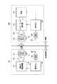
図1は、この発明の実施の形態1による給電システムの全体構成図である。図1を参照して、この給電システムは、給電設備100と、車両200とを備える。給電設備100は、高周波電源装置110と、一次コイル120と、一次自己共振コイル130と、電源ECU(Electronic Control Unit)140と、通信装置150とを含む。[Embodiment 1]
1 is an overall configuration diagram of a power feeding system according to Embodiment 1 of the present invention. With reference to FIG. 1, the power supply system includes a
高周波電源装置110は、所定の周波数を有する電力を生成して一次コイル120へ供給する。この高周波電源装置110により生成される電力は、一次自己共振コイル130と車両200の二次自己共振コイル210との磁場共鳴により一次自己共振コイル130から二次自己共振コイル210へ非接触で送電が行なわれるための高周波電力であり、その周波数は、たとえば1MHz〜10数MHzである。 The high frequency
また、高周波電源装置110は、図示されない反射電力センサを含み、高周波電源装置110から一次コイル120への電力供給時に発生する反射電力RFを反射電力センサにより検出して電源ECU140へ出力する。 In addition, high-frequency
一次コイル120は、電磁誘導により一次自己共振コイル130と磁気的に結合するように構成され、高周波電源装置110から供給される高周波電力を電磁誘導によって一次自己共振コイル130へ供給する。 The
一次自己共振コイル130は、コイル自身のインダクタンスとキャパシタC1の容量とによって形成されるLC共振コイルである。一次自己共振コイル130は、車両200の二次自己共振コイル210と電磁場を介して共鳴することにより二次自己共振コイル210へ非接触で送電する。この一次自己共振コイル130は、二次自己共振コイル210との距離や、二次自己共振コイル210と共鳴する際の共鳴周波数等に基づいて、一次自己共振コイル130と二次自己共振コイル210との共鳴強度を示すQ値およびその結合度を示すκが大きくなるようにその巻数が適宜設定される。なお、キャパシタC1を設けることなく、コイル自身の浮遊容量を一次自己共振コイル130の容量成分としてもよい。 The primary self-
電源ECU140は、上述した所定の周波数を有する電力を高周波電源装置110が生成するように高周波電源装置110を制御する。また、電源ECU140は、高周波電源装置110から反射電力RFの検出値を受け、その受けた反射電力RFの検出値を車両200へ送信するように通信装置150へ出力する。通信装置150は、車両200の通信装置260と無線通信を行なうための通信インターフェースであり、電源ECU140から受ける反射電力RFの検出値を車両200へ送信する。 The
一方、車両200は、二次自己共振コイル210と、二次コイル220と、インピーダンス整合器230と、負荷240と、車両ECU250と、通信装置260とを含む。 On the other hand,
二次自己共振コイル210は、コイル自身のインダクタンスとキャパシタC2の容量とによって形成されるLC共振コイルである。二次自己共振コイル210は、給電設備100の一次自己共振コイル130と電磁場を介して共鳴することにより一次自己共振コイル130から非接触で受電する。この二次自己共振コイル210も、一次自己共振コイル130との距離や共鳴周波数等に基づいて、Q値およびκが大きくなるようにその巻数が適宜設定される。なお、キャパシタC2を設けることなく、コイル自身の浮遊容量を二次自己共振コイル210の容量成分としてもよい。 The secondary self-
二次コイル220は、電磁誘導により二次自己共振コイル210と磁気的に結合するように構成され、二次自己共振コイル210により受電された電力を電磁誘導により取出してインピーダンス整合器230へ出力する。 The
インピーダンス整合器230は、二次コイル220と負荷240との間に設けられ、給電設備100の一次コイル120および一次自己共振コイル130ならびに車両200の二次自己共振コイル210および二次コイル220によって構成される共鳴系のインピーダンスを調整するための回路である。インピーダンス整合器230は、車両ECU250によってそのインピーダンスが変更されることによって共鳴系のインピーダンスを変更することができる。このインピーダンス整合器230の回路構成については、後ほど説明する。 The
負荷240は、給電設備100から電力の供給を受ける車両200の負荷を総括的に示したものである。負荷240は、後述のように、たとえば、二次自己共振コイル210によって受電された高周波電力を整流する整流器や、整流器により整流された電力を受ける充電器、充電器によって充電される蓄電装置などを含む。 The
車両ECU250は、負荷240を制御する。一例として、給電設備100から車両200への給電時においては、車両ECU250は、負荷240内で受電電力を受ける充電器(図示せず)により負荷240内の蓄電装置(図示せず)を充電するように充電器を制御する。 The
また、車両ECU250は、通信装置260によって受信された、高周波電源装置110の反射電力RFの検出値に基づいてインピーダンス整合器230を制御する。より詳しくは、車両ECU250は、一次コイル120および一次自己共振コイル130ならびに二次自己共振コイル210および二次コイル220によって構成される共鳴系より高周波電源装置110側のインピーダンスに共鳴系の入力インピーダンスを整合させるように、インピーダンス整合器230のインピーダンスを調整する。
通信装置260は、給電設備100の通信装置150と無線通信を行なうための通信インターフェースであり、給電設備100から受信した反射電力RFの検出値を車両ECU250へ出力する。
次に、共鳴法による非接触送電の原理について簡単に説明する。
図2は、共鳴法による送電に関する部分の等価回路図である。なお、この図2では、インピーダンス整合器230は図示されていない。図2を参照して、共鳴法では、2つの音叉が共鳴するのと同様に、同じ固有振動数を有する2つのLC共振回路が電磁場(近接場)において共鳴することによって、一方のLC共振回路から他方のLC共振回路へ電磁場を介して電力が伝送される。Next, the principle of contactless power transmission by the resonance method will be briefly described.
FIG. 2 is an equivalent circuit diagram of a portion related to power transmission by the resonance method. In FIG. 2, the
具体的には、一次コイル120に高周波電源装置110を接続し、電磁誘導により一次コイル120と磁気的に結合される一次自己共振コイル130へ高周波電力を供給する。一次自己共振コイル130は、自身と同じ共振周波数を有する二次自己共振コイル210と電磁場(近接場)を介して共鳴する。そうすると、一次自己共振コイル130から二次自己共振コイル210へ電磁場を介してエネルギー(電力)が移動する。二次自己共振コイル210へ移動したエネルギー(電力)は、電磁誘導により二次自己共振コイル210と磁気的に結合される二次コイル220によって取出され、負荷240へ供給される。 Specifically, the high frequency
入力側ポートP1と出力側ポートP2との間に設けられる、一次コイル120、一次自己共振コイル130、二次自己共振コイル210および二次コイル220によって構成される共鳴系のインピーダンスは、高周波電源装置110から負荷240へ供給される電力によって変化する。 The impedance of the resonance system constituted by the
そこで、再び図1を参照して、この実施の形態1では、給電設備100から給電を受ける車両200において、共鳴系のインピーダンスを調整するためのインピーダンス整合器230が設けられる。そして、高周波電源装置110の反射電力の検出値が給電設備100から車両200へ送信され、車両200において反射電力の検出値に基づきインピーダンス整合器230を制御することによって、共鳴系より高周波電源装置110側のインピーダンスに共鳴系の入力インピーダンスを整合させるように共鳴系のインピーダンスが調整される。より具体的には、車両200において反射電力の検出値に基づきインピーダンス整合器230を制御することによって、高周波電源装置110の反射電力が極小になるように共鳴系のインピーダンスが調整される。 Therefore, referring again to FIG. 1, in Embodiment 1, an
図3は、図1に示したインピーダンス整合器230の回路構成の一例を示した図である。図3を参照して、インピーダンス整合器230は、可変コンデンサ232,234と、コイル236とを含む。 FIG. 3 is a diagram illustrating an example of a circuit configuration of the
可変コンデンサ232は、二次コイル220(図1)に並列に接続される。可変コンデンサ234は、負荷240(図1)に並列に接続される。コイル236は、可変コンデンサ232の一端と可変コンデンサ234の一端との間に接続され、可変コンデンサ232の他端と可変コンデンサ234の他端とは、電気的に接続される。
このインピーダンス整合器230では、可変コンデンサ232,234の少なくとも一方の容量を変更することによってインピーダンスが変更される。なお、可変コンデンサ232,234の少なくとも一方を非可変のもので構成してもよいし、コイル236を可変コイルで構成してもよい。 In the
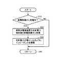
図4は、図1に示した車両ECU250により実行されるインピーダンス調整の処理手順を説明するためのフローチャートである。図4を参照して、車両ECU250は、給電設備100から受電中であるか否かを判定する(ステップS10)。給電設備100から受電中でないと判定されると(ステップS10においてNO)、車両ECU250は、以降の一連の処理を実行することなくステップS40へ処理を移行する。 FIG. 4 is a flowchart for illustrating a procedure of impedance adjustment executed by
ステップS10において、給電設備100から受電中であると判定されると(ステップS10においてNO)、車両ECU250は、給電設備100における高周波電源装置110の反射電力の検出値を通信装置260によって給電設備100から取得する(ステップS20)。 If it is determined in step S10 that power is being received from power supply facility 100 (NO in step S10),
そして、車両ECU250は、取得した反射電力の検出値に基づきインピーダンス整合器230を制御することによって、共鳴系より高周波電源装置110側のインピーダンスに共鳴系の入力インピーダンスを整合させるように共鳴系のインピーダンスを調整する。具体的には、車両ECU250は、反射電力の検出値に基づきインピーダンス整合器230を制御することによって、高周波電源装置110の反射電力が極小になるように共鳴系のインピーダンスを調整する(ステップS30)。 Then, the
図5は、図1に示した車両200の一例として示されるハイブリッド自動車の概略構成図である。図5を参照して、車両200は、蓄電装置310と、システムメインリレーSMR1と、昇圧コンバータ320と、インバータ330,332と、モータジェネレータ340,342と、エンジン350と、動力分割装置360と、駆動輪370とを含む。また、車両200は、二次自己共振コイル210と、二次コイル220と、インピーダンス整合器230と、整流器380と、充電器390と、システムメインリレーSMR2と、車両ECU250と、通信装置260とをさらに含む。 FIG. 5 is a schematic configuration diagram of a hybrid vehicle shown as an example of the
車両200は、エンジン350およびモータジェネレータ342を動力源として搭載する。エンジン350およびモータジェネレータ340,342は、動力分割装置360に連結される。そして、車両200は、エンジン350およびモータジェネレータ342の少なくとも一方が発生する駆動力によって走行する。エンジン350が発生する動力は、動力分割装置360によって2経路に分割される。すなわち、一方は駆動輪370へ伝達される経路であり、もう一方はモータジェネレータ340へ伝達される経路である。
モータジェネレータ340は、交流回転電機であり、たとえばロータに永久磁石が埋設された三相交流同期電動機から成る。モータジェネレータ340は、動力分割装置360を介してエンジン350の運動エネルギーを用いて発電する。たとえば、蓄電装置310の充電状態(「SOC(State Of Charge)」とも称される。)が予め定められた値よりも低くなると、エンジン350が始動してモータジェネレータ340により発電が行なわれ、蓄電装置310が充電される。
モータジェネレータ342も、交流回転電機であり、モータジェネレータ340と同様に、たとえばロータに永久磁石が埋設された三相交流同期電動機から成る。モータジェネレータ342は、蓄電装置310に蓄えられた電力およびモータジェネレータ340により発電された電力の少なくとも一方を用いて駆動力を発生する。そして、モータジェネレータ342の駆動力は、駆動輪370に伝達される。 The
また、車両の制動時や下り斜面での加速度低減時には、運動エネルギーや位置エネルギーとして車両に蓄えられた力学的エネルギーが駆動輪370を介してモータジェネレータ342の回転駆動に用いられ、モータジェネレータ342が発電機として作動する。これにより、モータジェネレータ342は、走行エネルギーを電力に変換して制動力を発生する回生ブレーキとして作動する。そして、モータジェネレータ342により発電された電力は、蓄電装置310に蓄えられる。 Further, when braking the vehicle or reducing acceleration on the down slope, the mechanical energy stored in the vehicle as kinetic energy or positional energy is used to drive the
動力分割装置360は、サンギヤと、ピニオンギヤと、キャリアと、リングギヤとを含む遊星歯車から成る。ピニオンギヤは、サンギヤおよびリングギヤと係合する。キャリアは、ピニオンギヤを自転可能に支持するとともに、エンジン350のクランクシャフトに連結される。サンギヤは、モータジェネレータ340の回転軸に連結される。リングギヤはモータジェネレータ342の回転軸および駆動輪270に連結される。 Power split device 360 includes a planetary gear including a sun gear, a pinion gear, a carrier, and a ring gear. The pinion gear engages with the sun gear and the ring gear. The carrier supports the pinion gear so as to be able to rotate and is coupled to the crankshaft of the engine 350. The sun gear is coupled to the rotation shaft of
システムメインリレーSMR1は、蓄電装置310と昇圧コンバータ320との間に配設され、車両ECU250からの信号に応じて蓄電装置310を昇圧コンバータ320に電気的に接続する。昇圧コンバータ320は、正極線PL2の電圧を蓄電装置310の出力電圧以上の電圧に昇圧する。なお、昇圧コンバータ320は、たとえば直流チョッパ回路から成る。インバータ330,332は、それぞれモータジェネレータ340,342を駆動する。なお、インバータ330,332は、たとえば三相ブリッジ回路から成る。 System main relay SMR1 is arranged between
二次自己共振コイル210および二次コイル220は、図1や図2で説明したとおりである。また、インピーダンス整合器230は、図1や図3で説明したとおりである。整流器380は、二次コイル220によって取出された交流電力を整流する。システムメインリレーSMR2は、整流器380と蓄電装置310との間に配設され、車両ECU250からの信号に応じて整流器380を蓄電装置310に電気的に接続する。 The secondary self-
車両ECU250は、走行モード時、システムメインリレーSMR1,SMR2をそれぞれオン,オフにする。そして、車両ECU250は、車両の走行時、アクセル開度や車両速度、その他種々のセンサからの信号に基づいて、昇圧コンバータ320およびモータジェネレータ340,342を駆動するための信号を生成し、その生成した信号を昇圧コンバータ320およびインバータ330,332へ出力する。
また、給電設備100(図1)から車両200への給電が行なわれるとき、車両ECU250は、システムメインリレーSMR2をオンにする。これにより、二次自己共振コイル210によって受電された電力が蓄電装置310へ供給される。そして、給電設備100から車両200への給電時、車両ECU250は、充電器390を制御するとともに、インピーダンス整合器230を制御することによって共鳴系のインピーダンスを上述のように調整する。 Further, when power is supplied from power supply facility 100 (FIG. 1) to
なお、システムメインリレーSMR1,SMR2をともにオンさせることによって、車両の走行中に給電設備1から受電することも可能である。 It is also possible to receive power from power supply facility 1 while the vehicle is running by turning on system main relays SMR1 and SMR2.
なお、二次自己共振コイル210からみて整流器380以降の各機器によって、図1に示した負荷240が構成される。 In addition, the
以上のように、この実施の形態1においては、高周波電源装置110の反射電力の検出値が給電設備100から車両200へ送信される。車両200には、給電設備100の一次コイル120および一次自己共振コイル130ならびに車両200の二次自己共振コイル210および二次コイル220によって構成される共鳴系のインピーダンスを調整するためのインピーダンス整合器230が設けられ、給電設備100から受信した反射電力の検出値に基づいてインピーダンス整合器230が制御される。これにより、車両200側のみで共鳴系のインピーダンスが調整される。したがって、この実施の形態1によれば、効率のよい給電を簡易な構成で実現することができる。 As described above, in the first embodiment, the detected value of the reflected power of the high frequency
[変形例]
上記の実施の形態1においては、高周波電源装置110の反射電力の検出値を給電設備100から車両200へ送信し、車両200において受信された反射電力の検出値に基づいて共鳴系のインピーダンスを調整するものとした。[Modification]
In the first embodiment, the detected value of the reflected power of the high frequency
ところで、上述したように、共鳴系のインピーダンスは、高周波電源装置110から負荷240へ供給される電力によって変化する。これは、言い換えると、高周波電源装置110から負荷240へ供給される電力に応じて共鳴系のインピーダンスは変化し、すなわち、高周波電源装置110から負荷240へ供給される電力に応じて共鳴系の最適なインピーダンスが変化する。 By the way, as described above, the impedance of the resonance system varies depending on the electric power supplied from the high frequency
そこで、高周波電源装置110から負荷240へ送電される電力が分かっていれば、その電力値を給電設備100から車両200へ送信し、車両200においてその電力値に基づいて共鳴系のインピーダンスを調整してもよい。 Therefore, if the power transmitted from high frequency
この変形例による給電システムの全体構成は、図1に示した実施の形態1による給電システムと同じである。 The overall configuration of the power feeding system according to this modification is the same as that of the power feeding system according to the first embodiment shown in FIG.
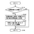
図6は、この変形例における車両ECU250により実行されるインピーダンス調整の処理手順を説明するためのフローチャートである。図6を参照して、給電設備100から受電中であると判定されると(ステップS110においてYES)、車両ECU250は、給電設備100から車両200へ送電される電力値を通信装置260によって給電設備100から取得する(ステップS120)。すなわち、この変形例においては、高周波電源装置110から負荷240へ送電される予め定められた電力値が給電設備100から車両200へ送信され、車両200の通信装置260によってその電力値が受信される。 FIG. 6 is a flowchart for illustrating a procedure of impedance adjustment executed by
そして、車両ECU250は、その取得した電力値に基づきインピーダンス整合器230を制御することによって、共鳴系のインピーダンスを調整する(ステップS130)。より詳しくは、車両ECU250は、給電設備100から取得した電力値に基づきインピーダンス整合器230を制御することによって、共鳴系より高周波電源装置110側のインピーダンスに共鳴系の入力インピーダンスを整合させるように共鳴系のインピーダンスを調整する。 Then, the
上述のように、共鳴系のインピーダンスは、高周波電源装置110から負荷240へ供給される電力によって変化する。そこで、一例として、高周波電源装置110から負荷240へ送電される電力に応じてインピーダンス整合器230によるインピーダンスの調整量を予め決定しておき、給電設備100から取得した電力値に基づいてインピーダンス整合器230を制御することによって共鳴系のインピーダンスを調整することができる。 As described above, the impedance of the resonance system varies depending on the electric power supplied from the high frequency
以上のように、この変形例によっても、実施の形態1と同様の効果を得ることが可能である。 As described above, this modification can also provide the same effects as those of the first embodiment.
[実施の形態2]
上記の実施の形態1および変形例においては、給電設備100側の電力情報(実施の形態1においては、反射電力の検出値、変形例においては、給電設備100から車両へ送電される電力値)に基づいて共鳴系のインピーダンスを調整するものとした。この実施の形態2では、給電設備100から車両200へ供給される電力を一定とし、車両200の負荷240(図1)の受電電力に基づいて共鳴系のインピーダンスが調整される。[Embodiment 2]
In the first embodiment and the modification described above, the power information on the
この実施の形態2による給電システムの全体構成は、図1に示した実施の形態1による給電システムと基本的に同じであるが、給電設備150の通信装置150および車両200の通信装置260は設けなくてもよい。 The overall configuration of the power supply system according to the second embodiment is basically the same as that of the power supply system according to the first embodiment shown in FIG. 1, but the
図7は、実施の形態2における車両ECU250により実行されるインピーダンス調整の処理手順を説明するためのフローチャートである。図7を参照して、給電設備100から受電中であると判定されると(ステップS210においてYES)、車両ECU250は、負荷240(図1)の受電電力を検出する(ステップS220)。一例として、充電器390(図5)において電力が検出され、その検出値が車両ECU250へ出力される。 FIG. 7 is a flowchart for illustrating a procedure of impedance adjustment executed by
そして、車両ECU250は、検出された負荷240の受電電力に基づきインピーダンス整合器230を制御することによって、共鳴系より高周波電源装置110側のインピーダンスに共鳴系の入力インピーダンスを整合させるように共鳴系のインピーダンスを調整する。具体的には、車両ECU250は、負荷240の受電電力に基づきインピーダンス整合器230を制御することによって、負荷240の受電電力が極大となるように共鳴系のインピーダンスを調整する(ステップS230)。 Then, the
以上のように、この実施の形態2によっても、車両200側のみで共鳴系のインピーダンスを調整できるので、効率のよい給電を簡易な構成で実現することができる。 As described above, according to the second embodiment as well, since the impedance of the resonance system can be adjusted only on the
なお、上記の実施の形態1および変形例においては、通信装置150,260を用いて給電設備100から車両200へ電力情報を送信するものとしたが、給電設備100から車両200へ送出される電力に電力情報を信号として重畳することによって給電設備100から車両200へ電力情報を送信することも可能である。 In Embodiment 1 and the modification described above, power information is transmitted from
また、上記の各実施の形態においては、一次コイル120を用いて電磁誘導により一次自己共振コイル130への給電を行ない、二次コイル220を用いて電磁誘導により二次自己共振コイル210から電力を取出すものとしたが、一次コイル120を設けることなく高周波電源装置110から一次自己共振コイル130へ直接給電し、二次コイル220を設けることなく二次自己共振コイル210から電力を直接取出してもよい。 In each of the above embodiments, the primary self-
また、上記においては、一対の自己共振コイルを共鳴させることによって送電するものとしたが、共鳴器として一対の自己共振コイルに代えて一対の高誘電体ディスクを用いてもよい。高誘電体ディスクは、高誘電率材から成り、たとえばTiO2やBaTi4O9、LiTaO3等が用いられる。In the above description, power is transmitted by resonating a pair of self-resonant coils. However, a pair of high dielectric disks may be used instead of the pair of self-resonant coils as a resonator. The high dielectric disk is made of a high dielectric constant material, and for example, TiO2 , BaTi4 O9 , LiTaO3 or the like is used.
また、上記においては、車両200の一例として、動力分割装置360によりエンジン350の動力を分割して駆動輪370とモータジェネレータ340とに伝達可能なシリーズ/パラレル型のハイブリッド自動車について説明したが、この発明は、その他の形式のハイブリッド自動車にも適用可能である。すなわち、たとえば、モータジェネレータ340を駆動するためにのみエンジン350を用い、モータジェネレータ342でのみ車両の駆動力を発生する、いわゆるシリーズ型のハイブリッド自動車や、エンジン350が生成した運動エネルギーのうち回生エネルギーのみが電気エネルギーとして回収されるハイブリッド自動車、エンジンを主動力として必要に応じてモータがアシストするモータアシスト型のハイブリッド自動車などにもこの発明は適用可能である。また、この発明は、エンジン350を備えずに電力のみで走行する電気自動車や、直流電源として蓄電装置310に加えて燃料電池をさらに備える燃料電池車にも適用可能である。 In the above description, as an example of the
なお、上記において、車両200は、この発明における「受電装置」の一実施例に対応し、高周波電源装置110は、この発明における「電源装置」の一実施例に対応する。また、一次自己共振コイル130および一次コイル120は、この発明における「送電用共鳴器」の一実施例を形成し、二次自己共振コイル210および二次コイル220は、この発明における「受電用共鳴器」の一実施例を形成する。さらに、通信装置150,260は、それぞれこの発明における「第1の通信装置」および「第2の通信装置」の一実施例に対応し、車両ECU250は、この発明における「制御装置」の一実施例に対応する。 In the above,
今回開示された実施の形態は、すべての点で例示であって制限的なものではないと考えられるべきである。本発明の範囲は、上記した実施の形態の説明ではなくて特許請求の範囲によって示され、特許請求の範囲と均等の意味および範囲内でのすべての変更が含まれることが意図される。 The embodiment disclosed this time should be considered as illustrative in all points and not restrictive. The scope of the present invention is shown not by the above description of the embodiments but by the scope of claims for patent, and is intended to include meanings equivalent to the scope of claims for patent and all modifications within the scope.
100 給電設備、110 高周波電源装置、120 一次コイル、130 一次自己共振コイル、140 電源ECU、150,260 通信装置、210 二次自己共振コイル、220 二次コイル、230 インピーダンス整合器、232,234 可変コンデンサ、236 コイル、240 負荷、250 車両ECU、310 蓄電装置、320 昇圧コンバータ、330,332 インバータ、340,342 モータジェネレータ、350 エンジン、360 動力分割装置、370 駆動輪、380 整流器、390 充電器、SMR1,SMR2 システムメインリレー。 DESCRIPTION OF
Claims (6)
Translated fromJapanese前記給電設備から給電を受ける受電装置とを備え、
前記給電設備は、
所定の周波数を有する電力を発生する電源装置と、
前記電源装置により発生された電力を受け、前記受電装置へ非接触で送電するための電磁場を発生する送電用共鳴器と、
前記給電設備側の電力情報を前記受電装置へ送信する第1の通信装置とを含み、
前記受電装置は、
前記送電用共鳴器と電磁場を介して共鳴することにより前記送電用共鳴器から非接触で受電する受電用共鳴器と、
前記受電用共鳴器によって受電された電力を受ける蓄電装置と、
前記送電用共鳴器および前記受電用共鳴器によって構成される共鳴系のインピーダンスを調整するためのインピーダンス整合器と、
前記第1の通信装置から送信される前記電力情報を受信する第2の通信装置と、
前記第2の通信装置によって受信した前記電力情報に基づいて前記インピーダンス整合器を制御する制御装置とを含み、
前記第1の通信装置は、前記給電設備から前記受電装置へ送電される予め定められた電力値を前記電力情報として前記受電装置へ送信し、
前記制御装置は、前記給電設備から前記受電装置へ送電される電力と前記インピーダンスの調整量との予め定められた関係を用いて、前記第2の通信装置によって受信された前記電力値に基づいて前記インピーダンス整合器を制御する、給電システム。Power supply equipment,
A power receiving device that receives power from the power supply facility,
The power supply equipment is
A power supply device that generates electric power having a predetermined frequency;
A power transmission resonator that receives electric power generated by the power supply device and generates an electromagnetic field for transmitting power to the power reception device in a contactless manner;
A first communication device that transmits power information on the power supply facility side to the power receiving device,
The power receiving device is:
A power receiving resonator that receives power from the power transmitting resonator in a non-contact manner by resonating with the power transmitting resonator via an electromagnetic field;
A power storage device that receives power received by the power receiving resonator;
An impedance matching unit for adjusting impedance of a resonance system constituted by the power transmission resonator and the power reception resonator;
A second communication device that receives the power information transmitted from the first communication device;
A control device that controls the impedance matching unit based on the power information received by the second communication device;
The first communication device transmits a predetermined power value transmitted from the power supply facility to the power receiving device as the power information to the power receiving device,
The control device usesa predetermined relationship between the power transmitted from the power supply facility to the power receiving device and the adjustment amount of the impedance , based on the power value received by the second communication device. A power feeding system for controlling the impedance matching unit.
前記制御装置は、前記共鳴系より前記電源装置側のインピーダンスに前記共鳴系の入力インピーダンスを整合させるように前記インピーダンス可変回路のインピーダンスを調整する、請求項1に記載の給電システム。The impedance matching unit includes an impedance variable circuit,
2. The power feeding system accordingto claim1, wherein the control device adjusts an impedance of the impedance variable circuit so as to match an input impedance of the resonance system with an impedance closer to the power supply device than the resonance system.
前記受電用共鳴器によって受電された電力を受けて前記蓄電装置を充電する充電器と、
前記受電用共鳴器と前記充電器との間に設けられる整流器とをさらに含み、
前記インピーダンス整合器は、前記受電用共鳴器と前記整流器との間に設けられる、請求項1または2に記載の給電システム。The power receiving device is:
A charger for charging said power storage device receives electric power received by thepre-Symbol power receiving resonator,
A rectifier provided between the power receiving resonator and the charger;
It said impedance matching device is provided between the rectifier and the power receiving resonator, power feeding system according to claim 1or 2.
前記送電用共鳴器と電磁場を介して共鳴することにより前記送電用共鳴器から非接触で受電する受電用共鳴器と、
前記受電用共鳴器によって受電された電力を受ける蓄電装置と、
前記送電用共鳴器および前記受電用共鳴器によって構成される共鳴系のインピーダンスを調整するためのインピーダンス整合器と、
前記給電設備から送信される前記電力情報を受信する通信装置と、
前記通信装置によって受信した前記電力情報に基づいて前記インピーダンス整合器を制御する制御装置とを備え、
前記給電設備から前記車両へ送電される予め定められた電力値が前記電力情報として前記給電設備から前記車両へ送信され、
前記制御装置は、前記給電設備から前記車両へ送電される電力と前記インピーダンスの調整量との予め定められた関係を用いて、前記通信装置によって受信された前記電力値に基づいて前記インピーダンス整合器を制御する、車両。A vehicle that receives power from a power feeding facility in a contactless manner, wherein the power feeding facility generates an electromagnetic field for transmitting power to the vehicle in a contactless manner by a power transmission resonator and transmits power information on the power feeding facility side to the vehicle. Send
A power receiving resonator that receives power from the power transmitting resonator in a non-contact manner by resonating with the power transmitting resonator via an electromagnetic field;
A power storage device that receives power received by the power receiving resonator;
An impedance matching unit for adjusting impedance of a resonance system constituted by the power transmission resonator and the power reception resonator;
A communication device for receiving the power information transmitted from the power supply facility;
A control device for controlling the impedance matching unit based on the power information received by the communication device;
A predetermined power value transmitted from the power supply facility to the vehicle is transmitted from the power supply facility to the vehicle as the power information,
The control device usesthe predetermined relationship between the power transmitted from the power supply facility to the vehicle and the adjustment amount of the impedance, and based on the power value received by the communication device, the impedance matching unit To control the vehicle.
前記制御装置は、前記共鳴系より電源側のインピーダンスに前記共鳴系の入力インピーダンスを整合させるように前記インピーダンス可変回路のインピーダンスを調整する、請求項4に記載の車両。The impedance matching unit includes an impedance variable circuit,
The vehicle according toclaim 4 , wherein the control device adjusts an impedance of the impedance variable circuit so as to match an input impedance of the resonance system with an impedance on a power source side of the resonance system.
前記受電用共鳴器と前記充電器との間に設けられる整流器とをさらに備え、
前記インピーダンス整合器は、前記受電用共鳴器と前記整流器との間に設けられる、請求項4または5に記載の車両。A charger for charging said power storage device receives electric power received by thepre-Symbol power receiving resonator,
A rectifier provided between the power receiving resonator and the charger;
The vehicle according toclaim 4 , wherein the impedance matching unit is provided between the power receiving resonator and the rectifier.
Priority Applications (5)
| Application Number | Priority Date | Filing Date | Title |
|---|---|---|---|
| JP2010120226AJP5146488B2 (en) | 2010-05-26 | 2010-05-26 | Power feeding system and vehicle |
| EP11743322.7AEP2576273B1 (en) | 2010-05-26 | 2011-05-26 | Power feeding system and vehicle |
| US13/697,133US8947046B2 (en) | 2010-05-26 | 2011-05-26 | Power feeding system and vehicle |
| CN201180025857.3ACN102905930B (en) | 2010-05-26 | 2011-05-26 | Feeding power system and vehicle |
| PCT/IB2011/001125WO2011148254A2 (en) | 2010-05-26 | 2011-05-26 | Power feeding system and vehicle |
Applications Claiming Priority (1)
| Application Number | Priority Date | Filing Date | Title |
|---|---|---|---|
| JP2010120226AJP5146488B2 (en) | 2010-05-26 | 2010-05-26 | Power feeding system and vehicle |
Publications (2)
| Publication Number | Publication Date |
|---|---|
| JP2011250555A JP2011250555A (en) | 2011-12-08 |
| JP5146488B2true JP5146488B2 (en) | 2013-02-20 |
Family
ID=44630110
Family Applications (1)
| Application Number | Title | Priority Date | Filing Date |
|---|---|---|---|
| JP2010120226AActiveJP5146488B2 (en) | 2010-05-26 | 2010-05-26 | Power feeding system and vehicle |
Country Status (5)
| Country | Link |
|---|---|
| US (1) | US8947046B2 (en) |
| EP (1) | EP2576273B1 (en) |
| JP (1) | JP5146488B2 (en) |
| CN (1) | CN102905930B (en) |
| WO (1) | WO2011148254A2 (en) |
Families Citing this family (27)
| Publication number | Priority date | Publication date | Assignee | Title |
|---|---|---|---|---|
| JP5126324B2 (en) | 2010-09-10 | 2013-01-23 | トヨタ自動車株式会社 | Power supply apparatus and control method of power supply system |
| JP2012143117A (en)* | 2011-01-06 | 2012-07-26 | Toyota Industries Corp | Non-contact power transmission device |
| JP5732870B2 (en)* | 2011-01-25 | 2015-06-10 | 株式会社明電舎 | Non-contact power supply apparatus and non-contact power supply method |
| EP2783890B1 (en)* | 2011-11-22 | 2020-02-12 | Toyota Jidosha Kabushiki Kaisha | Vehicle and power transfer system |
| KR101338654B1 (en) | 2011-12-19 | 2013-12-06 | 엘지이노텍 주식회사 | Apparatus for transmitting wireless power, apparatus for receiving wireless power, system for transmitting wireless power and method for transmitting wireless power |
| TWI587597B (en) | 2012-02-17 | 2017-06-11 | Lg伊諾特股份有限公司 | Wireless power transmitter, wireless power receiver, and power transmission method of wireless power transmitting system |
| US9735625B2 (en) | 2012-05-11 | 2017-08-15 | Toyota Jidosha Kabushiki Kaisha | Electric power transmission device, electric power reception device, vehicle, and non-contact electric power feed system |
| JP5747863B2 (en) | 2012-05-11 | 2015-07-15 | トヨタ自動車株式会社 | Vehicle, power receiving device, power transmitting device, and non-contact power feeding system |
| CN103124302A (en)* | 2012-06-08 | 2013-05-29 | 王洪洋 | Technology for reusing radio frequency reflected signals of mobile phone |
| WO2014030690A1 (en)* | 2012-08-23 | 2014-02-27 | 株式会社 豊田自動織機 | Non-contact power transmission equipment |
| US9963040B2 (en) | 2012-09-13 | 2018-05-08 | Toyota Jidosha Kabushiki Kaisha | Non-contact power supply system, and power transmission device and vehicle used therein |
| JP5643270B2 (en) | 2012-09-13 | 2014-12-17 | トヨタ自動車株式会社 | Vehicle and contactless power supply system |
| JP2014060862A (en)* | 2012-09-18 | 2014-04-03 | Toyota Industries Corp | Non-contact power transmission device |
| KR102008810B1 (en) | 2012-11-12 | 2019-08-08 | 엘지이노텍 주식회사 | Wireless power transmitting apparatus and method |
| CN103078381B (en)* | 2013-01-27 | 2015-06-17 | 中国科学院电工研究所 | Wireless charging device for electric vehicle and output control method thereof |
| JP6169380B2 (en)* | 2013-03-19 | 2017-07-26 | 日東電工株式会社 | Wireless power transmission device, heat generation control method for wireless power transmission device, and method for manufacturing wireless power transmission device |
| WO2015001672A1 (en)* | 2013-07-05 | 2015-01-08 | 株式会社 東芝 | Control apparatus and method, and wireless power transfer apparatus |
| JP6302113B2 (en)* | 2013-07-05 | 2018-03-28 | 株式会社東芝 | Control device, control method, and wireless power transmission device |
| JP6118411B2 (en)* | 2013-07-05 | 2017-04-19 | 株式会社東芝 | Control device, control method, and wireless power transmission device |
| JP6111160B2 (en) | 2013-07-18 | 2017-04-05 | 本田技研工業株式会社 | Electric vehicle |
| JP6220609B2 (en)* | 2013-09-11 | 2017-10-25 | シャープ株式会社 | Charging circuit |
| US9882419B2 (en) | 2014-02-14 | 2018-01-30 | Massachusetts Institute Of Technology | Adaptive control of wireless power transfer |
| US9800076B2 (en) | 2014-02-14 | 2017-10-24 | Massachusetts Institute Of Technology | Wireless power transfer |
| US20160181853A1 (en)* | 2014-12-23 | 2016-06-23 | Intel Corporation | Low emission coil topology for wireless charging |
| KR20220070337A (en) | 2014-12-31 | 2022-05-30 | 메사추세츠 인스티튜트 오브 테크놀로지 | Adaptive control of wireless power transfer |
| US10020793B2 (en)* | 2015-01-21 | 2018-07-10 | Qualcomm Incorporated | Integrated filters in output match elements |
| CN113162245B (en)* | 2021-03-23 | 2023-11-10 | Oppo广东移动通信有限公司 | Charging circuit, chip and device |
Family Cites Families (14)
| Publication number | Priority date | Publication date | Assignee | Title |
|---|---|---|---|---|
| JP3488166B2 (en)* | 2000-02-24 | 2004-01-19 | 日本電信電話株式会社 | Contactless IC card system, its reader / writer and contactless IC card |
| JP2002272134A (en)* | 2001-03-08 | 2002-09-20 | Mitsubishi Heavy Ind Ltd | Non-contact feeding device of high frequency power, and method therefor |
| US7825543B2 (en)* | 2005-07-12 | 2010-11-02 | Massachusetts Institute Of Technology | Wireless energy transfer |
| JP4453741B2 (en)* | 2007-10-25 | 2010-04-21 | トヨタ自動車株式会社 | Electric vehicle and vehicle power supply device |
| US20090284369A1 (en)* | 2008-05-13 | 2009-11-19 | Qualcomm Incorporated | Transmit power control for a wireless charging system |
| JP2009290644A (en)* | 2008-05-30 | 2009-12-10 | Sony Corp | Transponder, interrogator and communication device |
| JP5241381B2 (en)* | 2008-08-25 | 2013-07-17 | 株式会社日立製作所 | Power receiver |
| WO2010035321A1 (en)* | 2008-09-25 | 2010-04-01 | トヨタ自動車株式会社 | Power supply system and electric vehicle |
| US20120112691A1 (en)* | 2008-09-27 | 2012-05-10 | Kurs Andre B | Wireless energy transfer for vehicles |
| JP5375032B2 (en)* | 2008-11-04 | 2013-12-25 | 株式会社豊田自動織機 | Non-contact power transmission device and design method of non-contact power transmission device |
| CN102209647B (en)* | 2008-11-07 | 2013-11-13 | 丰田自动车株式会社 | Vehicle power supply system, electric vehicle, and vehicle power supply equipment |
| JP5114372B2 (en) | 2008-12-09 | 2013-01-09 | 株式会社豊田自動織機 | Power transmission method and non-contact power transmission apparatus in non-contact power transmission apparatus |
| JP5727146B2 (en)* | 2010-02-05 | 2015-06-03 | 日本無線株式会社 | Radar antenna device, radar antenna drive unit, and ship radar antenna power supply device |
| US8638063B2 (en)* | 2010-10-13 | 2014-01-28 | Tesla Motors, Inc. | AC current control of mobile battery chargers |
- 2010
- 2010-05-26JPJP2010120226Apatent/JP5146488B2/enactiveActive
- 2011
- 2011-05-26EPEP11743322.7Apatent/EP2576273B1/enactiveActive
- 2011-05-26USUS13/697,133patent/US8947046B2/enactiveActive
- 2011-05-26CNCN201180025857.3Apatent/CN102905930B/enactiveActive
- 2011-05-26WOPCT/IB2011/001125patent/WO2011148254A2/enactiveApplication Filing
Also Published As
| Publication number | Publication date |
|---|---|
| EP2576273A2 (en) | 2013-04-10 |
| US8947046B2 (en) | 2015-02-03 |
| CN102905930B (en) | 2015-08-12 |
| EP2576273B1 (en) | 2019-09-18 |
| US20130057207A1 (en) | 2013-03-07 |
| CN102905930A (en) | 2013-01-30 |
| WO2011148254A3 (en) | 2012-01-12 |
| JP2011250555A (en) | 2011-12-08 |
| WO2011148254A8 (en) | 2012-05-10 |
| WO2011148254A2 (en) | 2011-12-01 |
Similar Documents
| Publication | Publication Date | Title |
|---|---|---|
| JP5146488B2 (en) | Power feeding system and vehicle | |
| JP4868077B2 (en) | Power feeding system and electric vehicle | |
| JP4865001B2 (en) | Non-contact power supply equipment, non-contact power receiving device and non-contact power supply system | |
| JP5304624B2 (en) | Power supply device, vehicle, and vehicle power supply system | |
| US8380380B2 (en) | Electric power reception apparatus and electrical powered vehicle | |
| US8418823B2 (en) | Electrically powered vehicle | |
| JP4947241B2 (en) | Coil unit, contactless power receiving device, contactless power transmitting device, contactless power feeding system, and vehicle | |
| JP5287863B2 (en) | Non-contact power receiving apparatus and vehicle equipped with the same | |
| JP5703988B2 (en) | Power receiving device, power transmitting device, vehicle, and non-contact power feeding system | |
| JP5768878B2 (en) | vehicle | |
| US20120032521A1 (en) | Non-contact electric power feeding equipment and non-contact electric power feeding system | |
| JP2013005614A (en) | Power transmission equipment, power incoming equipment, vehicle, and non-contact power supply system | |
| JP2010167898A (en) | Hybrid vehicle | |
| JP5287115B2 (en) | Vehicle power reception control device and vehicle including the same | |
| CN103522902A (en) | Non-contact powered device and vehicle provided with non-contact powered device | |
| JP2010166669A (en) | Electric vehicle | |
| JP2015027224A (en) | Non-contact power receiving device |
Legal Events
| Date | Code | Title | Description |
|---|---|---|---|
| A977 | Report on retrieval | Free format text:JAPANESE INTERMEDIATE CODE: A971007 Effective date:20120406 | |
| A131 | Notification of reasons for refusal | Free format text:JAPANESE INTERMEDIATE CODE: A131 Effective date:20120417 | |
| A521 | Request for written amendment filed | Free format text:JAPANESE INTERMEDIATE CODE: A523 Effective date:20120528 | |
| A131 | Notification of reasons for refusal | Free format text:JAPANESE INTERMEDIATE CODE: A131 Effective date:20120626 | |
| A521 | Request for written amendment filed | Free format text:JAPANESE INTERMEDIATE CODE: A523 Effective date:20120824 | |
| TRDD | Decision of grant or rejection written | ||
| A01 | Written decision to grant a patent or to grant a registration (utility model) | Free format text:JAPANESE INTERMEDIATE CODE: A01 Effective date:20121030 | |
| A61 | First payment of annual fees (during grant procedure) | Free format text:JAPANESE INTERMEDIATE CODE: A61 Effective date:20121112 | |
| R151 | Written notification of patent or utility model registration | Ref document number:5146488 Country of ref document:JP Free format text:JAPANESE INTERMEDIATE CODE: R151 | |
| FPAY | Renewal fee payment (event date is renewal date of database) | Free format text:PAYMENT UNTIL: 20151207 Year of fee payment:3 |