JP5145901B2 - Robot system - Google Patents
Robot systemDownload PDFInfo
- Publication number
- JP5145901B2 JP5145901B2JP2007305205AJP2007305205AJP5145901B2JP 5145901 B2JP5145901 B2JP 5145901B2JP 2007305205 AJP2007305205 AJP 2007305205AJP 2007305205 AJP2007305205 AJP 2007305205AJP 5145901 B2JP5145901 B2JP 5145901B2
- Authority
- JP
- Japan
- Prior art keywords
- robot
- welding
- electrode grinding
- electrode
- grinding device
- Prior art date
- Legal status (The legal status is an assumption and is not a legal conclusion. Google has not performed a legal analysis and makes no representation as to the accuracy of the status listed.)
- Active
Links
Images


Landscapes
- Manipulator (AREA)
- Resistance Welding (AREA)
Description
Translated fromJapanese本発明は、7関節ロボットを使用してスポット溶接やハンドリングを行うロボットシステムに関する。 The present invention relates to a robot system that performs spot welding and handling using a seven-joint robot.
従来のスポット溶接ロボット装置では、スポットガンをロボットの手首部に備えたロボットとスポットガンの電極を研磨する電極研削機から構成されたものが開示されている(例えば、特許文献1)。図4を用いて従来のスポット溶接ロボット装置について説明する。制御装置1に接続された電極研削機2が、溶接ロボット3のアーム4の先端に取付けられた溶接ガン5の溶接電極6を研削する。
電極研削装置2は溶接ロボット3とは分離された状態で、スタンド状の固定台上に設置されている。溶接ロボット3は6関節を有する。ロボットにはモータを駆動または制御する動力用ケーブル及び信号ケーブル10が制御装置1からロボットまで配設されている。同様に電極研削装置を駆動または制御する動力用ケーブル及び信号ケーブル11も制御装置1から電極研削装置まで配設されていた。
溶接ロボット3は、ライン上を流れてくる自動車の車体等の被加工物の所定箇所にスポット溶接を施す。
電極研削機2は、周知の電極チップカッタであり、制御装置1からの指令に応じて、溶接ガン5に取付けられた溶接電極6を研削する。制御装置1は、溶接ロボット3を制御して、所定の溶接作業を行わせる従来の溶接ロボット制御装置としての機能に加えて、溶接電極6の損耗を推定し、この推定値に基づいて電極研削機2を制御し、溶接電極6を適切に研削するための機能も備える。
また、従来のハンドリングロボットとしては、治具を持ち替えながら作業するロボットが提案されている(例えば、特許文献2参照)。ハンドリングロボットは、該当する車種の部品セット治具を前記部品セット治具収納ラックの中から選択して持ち替えた上で、その選択した部品セット治具で前記部品搬送台車上のリアパネルをクランプして部品セット治具ごと前記部品セット治具位置決め装置に位置決めする機能を有し、前記ハンドリングロボットのロボットアームの先端の手首部には部品セット治具を持ち替えるためのツールチェンジャが設けられている。
The
The
The
Further, as a conventional handling robot, a robot that works while changing jigs has been proposed (see, for example, Patent Document 2). The handling robot selects and replaces the parts setting jig of the corresponding vehicle type from the parts setting jig storage rack, and then clamps the rear panel on the parts transport carriage with the selected parts setting jig. The part setting jig has a function of positioning with the part setting jig positioning device, and a tool changer for changing the part setting jig is provided at the wrist at the tip of the robot arm of the handling robot.
従来、電極研削装置や治具置き台はロボットと分離された状態である場合、生産ラインを立ち上げ時に、電極研削装置や治具置き台とロボットの供給業者は異なっているために、電極研削装置や治具置き台はロボットの近傍に設置されるにも関わらず、動力、信号供給ケーブルや固定台など分離された状態で供給されていた。従って、個別にケーブルの敷設、固定台の設置が必要であり、立ち上げ時間や管理工数の増大が問題となっており、生産ラインの稼動までの時間を短縮したいという要望があった。
また、生産ラインが短い方が、工場自体の増大を防ぎ、空調設備等の設備投資を抑制するために、ロボットシステムのフットプリントを小さくするとともに、ロボットを極力接近させて配置したいという要望がある。
また、生産数が多くなるに従って、ロボットの作業に関係のないエアーカットの時間を短縮して作業効率を上げたいといった要望もある。
しかしながら、従来のスポット溶接ロボット装置やハンドリングロボット装置では、電極研削装置と溶接ロボットが分離して構成されていたために、生産ラインの稼動までの時間を短縮できないという問題が生じていた。また、電極研削装置や治具置き台はロボットと分離された状態で、スタンド状の固定台上に設置されているため、生産設備を設計するにあたって、予めロボットの動作に支障をきたさない位置に配置する必要があるため、設備検討に時間がかかる問題も生じていた。この問題を解決するために、ロボットシミュレータを使って、事前にロボットの干渉チェックや動作チェックを行うことができるが、実機での確認作業を行う必要はあり、再度調整を行う必要があった。
また、電極研削装置設置や治具置き台の位置は作業に支障をきたさないように、作業時のロボット動作エリア外に設置するため、スポット溶接のチップ研磨作業時や治具交換作業時にはロボットは作業エリア外まで移動する必要があり、生産に寄与しない無駄な動作時間を必要といった問題も生じていた。
また、作業エリア外に電極研削装置設備エリアや治具置き台エリアが必要となり、設置面積の増加を招くといった問題も生じていた。
本発明はこのような問題点に鑑みてなされたものであり、複数台のロボットを接近配置でき、生産に寄与しない無駄な動作時間を最小にするロボットシステムを提供することを目的とする。Conventionally, when the electrode grinding device and jig stand are separated from the robot, the electrode grinding device and jig stand and the robot supplier are different when the production line is set up. Despite being installed in the vicinity of the robot, the device and jig stand were supplied in a separated state, such as power, signal supply cable, and fixed base. Therefore, it is necessary to individually lay cables and install a fixed base, and there is a problem of increase in start-up time and management man-hours, and there has been a desire to shorten the time until the production line is operated.
In addition, there is a demand for a shorter production line to reduce the footprint of the robot system and to place the robot as close as possible in order to prevent an increase in the factory itself and suppress capital investment for air conditioning equipment, etc. .
In addition, as the number of production increases, there is a demand to increase the work efficiency by reducing the time of air cut that is not related to the robot work.
However, in the conventional spot welding robot apparatus and handling robot apparatus, since the electrode grinding apparatus and the welding robot are configured separately, there has been a problem that the time until the operation of the production line cannot be shortened. In addition, since the electrode grinding device and the jig stand are separated from the robot and are installed on a stand-like fixed base, when designing the production equipment, the position of the robot will not be hindered in advance. Since it is necessary to arrange the equipment, there is a problem that it takes time to examine the equipment. In order to solve this problem, it is possible to perform robot interference check and operation check in advance using a robot simulator. However, it is necessary to perform confirmation work with an actual machine and to perform adjustment again.
In addition, the position of the electrode grinding device and the jig stand is placed outside the robot operation area at the time of work so that the work is not hindered. There is also a problem that it is necessary to move out of the work area and useless operating time that does not contribute to production.
In addition, an electrode grinding apparatus facility area and a jig stand area are required outside the work area, which causes a problem of increasing the installation area.
The present invention has been made in view of such problems, and an object of the present invention is to provide a robot system in which a plurality of robots can be arranged close to each other and wasteful operation time that does not contribute to production is minimized.
上記問題を解決するため、本発明は、次のように構成したのである。
請求項1に記載の発明は、基部に回転支持された旋回部、該旋回部に一端が水平軸周りに回転支持された下腕部、前記下腕部の他方端に一端が回転支持された肘部、前記肘部の他方端に一端が回転支持された上腕部、前記上腕部の他方端に手首部を備え、溶接を行うための器具が、溶接対象の反対側に相当するロボット背面側の前記旋回部に備えられたものである。
また、請求項2に記載の発明は、前記溶接を行うための器具が、スポット溶接を行うために電極研削装置、スポット溶接ガンの取り替え可能とするツールチェンジャ、または仮置き台の少なくともいずれか1つであるものである。
また、請求項3に記載の発明は、前記電極研削装置の制御用ケーブルを、前記ロボット制御用ケーブルと一体に配設したものである。
また、請求項4に記載の発明は、前記電極研削装置の制御用ケーブル及び動力用線状体が、前記ロボット内部に配設されているものである。In order to solve the above problem, the present invention is configured as follows.
According to the first aspect of the present invention, there is provided a swivel portion that is rotatably supported by a base portion, a lower arm portion that is supported at one end around a horizontal axis by the swivel portion, and one end that is rotatably supported at the other end of the lower arm portion. elbow, upper arm, one end to the other end of the elbow is rotatably supported, comprising a wrist unit to the other end of the upperarm, the device for performingweldingrobot back corresponding to the opposite side of the welded It is provided in theswivel part on the side .
According to a second aspect of the present invention, at least any one of an electrode grinding device, a tool changer that allows a spot welding gun to be replaced, and a temporary placing table are used for performing the welding. It is one.
According to a third aspect of the present invention, a control cable for the electrode grinding apparatus is disposed integrally with the robot control cable.
According to a fourth aspect of the present invention, a control cable and a power linear body of the electrode grinding apparatus are disposed inside the robot.
本発明によると、7関節ロボットを使用してスポット溶接を行う場合に、電極研削装置を省スペースでロボット一体に配置できるので、電極研削装置の設置検討が不要になり設備検討時間が短縮できる。また、ロボットの近傍に電極研削装置が設置できるので、電極研削装置までのロボットの移動時間を短縮できる。
また、7関節ロボットのデッドスペースに電極研削装置を配置できるので、電極研削装置面積を削減することができる。
また、7関節ロボットと電極研削装置の信号及びパワーケーブルをロボットの配線に取り込むことができるので、ユーザでの立ち上げ時の立ち上げ時間や管理工数の削減が可能になる。
また、ガン置き台を省スペースでロボット一体に配置できるので、ガン置き台の設置検討が不要になり設備検討時間が短縮できる。また、ロボットの近傍にガン置き台が設置できるので、ガン置き台までのロボットの移動時間を短縮できる。
また、仮置き台を省スペースでロボット一体に配置できるので、仮置き台の設置検討が不要になり設備検討時間が短縮できる。また、ロボットの近傍に仮置き台が設置できるので、仮置き台までのロボットの移動時間を短縮できる。According to thepresent invention, when spot welding is performed using a seven-joint robot, the electrode grinding apparatus can be arranged integrally with the robot in a space-saving manner, so that installation examination of the electrode grinding apparatus is not required, and equipment examination time can be shortened. In addition, since the electrode grinding apparatus can be installed in the vicinity of the robot, it is possible to shorten the movement time of the robot to the electrode grinding apparatus.
In addition, since the electrode grinding device can be arranged in the dead space of theseven- joint robot, the area of the electrode grinding device can be reduced.
Further, since the signal and power cable of the7- joint robot and the electrode grinding apparatus can be taken into the wiring of the robot, it is possible to reduce the start-up time and management man-hour at the time of start-up by the user.
In addition, since the table everygun can be placed on the robot together in a space-saving, cancer stand of the installation examination can be shortened facilities study time will be unnecessary. In addition, since a gun stand can be installed in the vicinity of the robot, the movement time of the robot to the gun stand can be shortened.
In addition,the temporary stand and can be arranged on the robot together in a space-saving, installation study of the temporary stage can be shortened facilities study time will be unnecessary. In addition, since a temporary table can be installed in the vicinity of the robot, the movement time of the robot to the temporary table can be shortened.
以下、本発明の実施の形態について図を参照して説明する。 Hereinafter, embodiments of the present invention will be described with reference to the drawings.
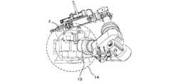
図1は、本発明のスポット溶接装置の斜視図である。図1において、3は7関節溶接ロボットであって、固定ベース4に固定されている。C1は旋回部であり第1のアーム体であり、J1軸周りに回転する。C2は下腕であり第2のアーム体であり、J2軸周りに回転する。C3は肘部であり第3のアーム体であり、J3軸周りに回転する。C4は上腕であり第4のアーム体であり、J4軸周りに回転する。C5は第5のアーム体であり、J5軸周りに回転する。C6は第6のアーム体であり、J6軸周りに回転する。C7は第7のアーム体(エンドエフェクタ)であり、J7軸周りに回転する。C5、C6及びC7で手首部を構成する。エンドエフェクタにはスポット溶接ガン5が取り付けられている。また、2は電極研削装置であり固定台9に取り外し可能にネジ止め設置されており、固定台9は7関節ロボット1のアーム体C1に取り外し可能にネジ止め設置されている。8は溶接対象物であり、たとえば自動車のボディや、パーツ部品等のスポット溶接接合が施行される対象ワークである。
本発明が特許文献1と異なる点は、スポット溶接ロボットを7軸関節で構成し、電極研削装置をスポット溶接ロボットの固定部に備えた部分である。FIG. 1 is a perspective view of the spot welding apparatus of the present invention. In FIG. 1,
The present invention is different from Patent Document 1 in that a spot welding robot is configured with a seven-axis joint and an electrode grinding apparatus is provided in a fixed portion of the spot welding robot.
7関節ロボットは、肘部C3の折り返し動作により旋回部後方に制御点を動作することが可能となる。図1では肘部の第3のアーム体C3がJ3軸周りに回転し、これに連動するように第4から第7のアーム体C4〜C7が回転することで、溶接対象8の反対側に相当するロボット背面に設置された溶接電極用研削装置2に電極部6を到達させている。 The seven-joint robot can move the control point to the rear of the turning unit by the folding operation of the elbow C3. In FIG. 1, the third arm body C3 of the elbow part rotates around the J3 axis, and the fourth to seventh arm bodies C4 to C7 rotate so as to interlock with the third arm body C3. The
次に制御装置からスポット溶接ロボット装置への配線について図1を用いて説明する。電極研削装置2は7関節溶接ロボットに付帯されるようになるため、同一経路の配線となる。本発明では一体ケーブル12に構成することを提供している。一体ケーブル12には、動力用ケーブル、信号ケーブルや流体を流すホース等が一体となって形成されている。この場合、動力用ケーブルと信号ケーブルとを、ケーブル内部で分離しても一体化したケーブルとして取り扱うことができる。
動力や冷却に流体を用いる場合も同様に一体化できるのは当然であり、全ての動力用線条体を指し、装置の要求により一体化を選択できる。
同様に、ロボット機体内の配線に電極研削装置を駆動または制御するパワーケーブルや信号ケーブルを内蔵することにより、ロボット製造時に電極研削装置用のロボット内部配線を完成させておき、ロボット完成後に、コネクタ等により電極研削装置との結合を完了するようなことが可能となる。Next, wiring from the control device to the spot welding robot device will be described with reference to FIG. Since the
Of course, when fluid is used for power and cooling, it can naturally be integrated in the same manner, and refers to all power wires, and integration can be selected according to the requirements of the apparatus.
Similarly, the power cable and signal cable for driving or controlling the electrode grinding device are built in the wiring inside the robot body, so that the robot internal wiring for the electrode grinding device is completed when the robot is manufactured. Thus, it is possible to complete the coupling with the electrode grinding apparatus.
次に、スポット溶接ロボット装置の設置状態について図2および図3を用いて説明する。図2は、スポット溶接ロボット装置の上面図であり、図3は背面図である。図2において、13のハッチングは、第2アーム体C2を投影した部分である。また、14は旋回部のアーム体C1の旋回中心を中心として第2のアーム体C2の旋回領域を示したものである。第2のアーム体C2の旋回領域は、6関節溶接ロボットの第2のアーム体の旋回領域と同等であり、必然的に占有される領域である。溶接電極研削装置2は、第2のアーム体C2の旋回領域の内側の固定台9に配置されている。
このように、必然的に占有される領域に溶接電極研削装置を配置することで、通常生産ラインで配置される複数台の溶接ロボットが互いに干渉することがなくなるので、よりワークへの接近性やスポットガンの姿勢を形成できる。
また、複数台のロボットが横方向に接近して配置される場合には、図3に示すようにロボット後方から見て、ロボットの幅寸法15内もしくは幅寸法15に近い溶接電極用研削装置設置幅寸法16で配置することで、接近配置の妨げにならずに済む。Next, the installation state of the spot welding robot apparatus will be described with reference to FIGS. FIG. 2 is a top view of the spot welding robot apparatus, and FIG. 3 is a rear view. In FIG. 2, the hatched 13 is a portion where the second arm body C2 is projected.
In this way, by arranging the welding electrode grinding device in the area that is inevitably occupied, a plurality of welding robots that are normally arranged on the production line will not interfere with each other. A spot gun posture can be formed.
In addition, when a plurality of robots are arranged close to each other in the lateral direction, as shown in FIG. 3, a welding electrode grinding device is installed in or near the
本発明ではユーザに届ける前に、ロボットにケーブル、固定台等全て取り付けられており、必要な調整も完了させておくことでユーザでの立ち上げ時間や管理工数の削減が可能になる。
また、電極研削装置と溶接ロボットとを一体に配置することが可能になるため、生産設備を設計するにあたって、予め溶接用ロボットの動作に支障をきたさない位置に配置する必要が無くなり、設備検討を短縮できる。
さらに、電極研削装置設置位置は溶接作業に支障をきたさないように、溶接作業エリア外に設置する必要が無く、ロボット近傍に設置できるため、研磨作業時には溶接ロボットは溶接作業エリア外まで移動する必要がなくなり、生産に寄与しない無駄な動作時間の削減が可能になる。
従来6軸のロボットでは自由度が不足に起因し、ロボットがアクセス困難なため周辺に設置されていた設備を、本発明のようにロボット旋回部に搭載することで、装置としてのまとまりを高めることができる。In the present invention, before delivery to the user, all of the cables, fixed bases, etc. are attached to the robot, and it is possible to reduce the startup time and management man-hours by completing the necessary adjustments.
In addition, since it is possible to arrange the electrode grinding device and the welding robot together, it is no longer necessary to place the welding machine in a position that does not hinder the operation of the welding robot in advance when designing the production equipment. Can be shortened.
Furthermore, it is not necessary to install the electrode grinding device outside the welding work area so as not to interfere with the welding work, and it can be installed near the robot, so the welding robot must move outside the welding work area during polishing work. As a result, wasteful operation time that does not contribute to production can be reduced.
A conventional 6-axis robot has a lack of flexibility, and it is difficult to access the robot, so the equipment installed in the vicinity is mounted on the robot turning part as in the present invention, thereby improving the unity of the device. Can do.
尚、電極研削装置に限らず、例えば2台以上のスポットガンを持ち替えて溶接を行う場合、ガン置き台をロボットの周辺に配置していたが、電極研削装置と同じく、溶接動作領域から離した位置にしか設置できずに、ロボット動作量が増加して、サイクルタイムが伸びるという問題があったが、本発明のように、旋回部にガン置き台を取付けることで、ガンチェンジ時にロボットの動作量が減少し、段取り変えの時間が短縮できる。
この場合、ロボット用ケーブルとガン置き台設置のチャッキング装置や入出力装置の動力及び信号ケーブル及びエア等を含む線状体の一体化が可能になる。In addition to the electrode grinding device, for example, when carrying out welding by changing two or more spot guns, the gun mount was placed around the robot, but, like the electrode grinding device, it was separated from the welding operation area. There was a problem that the robot movement amount increased and the cycle time was extended because it could only be installed at the position, but as in the present invention, by attaching a gun stand to the turning part, the robot operation at the time of the gun change The amount is reduced and the time for setup change can be shortened.
In this case, the robot cable can be integrated with the linear body including the power of the chucking device and input / output device installed on the gun stand, the signal cable, air, and the like.
また、ハンドリング用途においてワークの仮置き台をロボットの周辺に配置する例も見受けられるが、本発明のように、旋回部に仮置き台を設置することでサイクルタイムの短縮が可能となり、生産性の向上に貢献できる。
この場合、ロボット用ケーブルと仮置き台設置のジグ駆動や入出力装置の動力及び信号ケーブル及びエア等を含む線状体の一体化が可能になる。In addition, there is an example of placing a temporary table for workpieces around the robot in handling applications. However, as in the present invention, it is possible to shorten the cycle time by installing a temporary table on the swivel part. Can contribute to the improvement.
In this case, it becomes possible to integrate a robot cable and a linear body including a jig drive for installing a temporary table, power of an input / output device, a signal cable, air, and the like.
C1 第1のアーム体
C2 第2のアーム体
C3 第3のアーム体
C4 第4のアーム体
C5 第5のアーム体
C6 第6のアーム体
C7 第7のアーム体(エンドエフェクタ)
J1 関節軸
J2 関節軸
J3 関節軸
J4 関節軸
J5 関節軸
J6 関節軸
J7 関節軸
1 制御装置
2 電極研削装置
3 溶接ロボット
4 固定ベース
5 スポットガン
6 電極
7 設置距離
8 溶接対象
9 固定台
10 パワーケーブル及び信号ケーブル
11 パワーケーブル及び信号ケーブル
12 一体ケーブル
13 C2アームのベース面への投影図
14 旋回中心回りに回転させた干渉半径
15 ロボット幅寸法
16 溶接電極用研削装置設置幅寸法C1 1st arm body C2 2nd arm body C3 3rd arm body C4 4th arm body C5 5th arm body C6 6th arm body C7 7th arm body (end effector)
J1 joint axis J2 joint axis J3 joint axis J4 joint axis J5 joint axis J6 joint axis J7 joint axis 1
Claims (5)
Translated fromJapanese溶接を行うための器具が、
溶接対象の反対側に相当するロボット背面側の前記旋回部に備えられたこと
を特徴とするロボットシステム。A swivel portion rotatably supported by a base, a lower arm portion whose one end is rotatably supported around a horizontal axis, an elbow portion whose one end is rotatably supported by the other end of the lower arm portion, and the other end of the elbow portion An upper arm whose one end is rotatably supported, and a wrist at the other end of the upper arm,
An instrument for performingwelding,
A robot system characterized in that it is provided in therevolving part on the back side of the robot corresponding to the opposite side of the welding target .
Robot system accordingto claim 1to 4 wherein the control cable and a power linear body electrode grinding apparatus, characterized in that disposed inside therobot.
Priority Applications (1)
| Application Number | Priority Date | Filing Date | Title |
|---|---|---|---|
| JP2007305205AJP5145901B2 (en) | 2007-11-27 | 2007-11-27 | Robot system |
Applications Claiming Priority (1)
| Application Number | Priority Date | Filing Date | Title |
|---|---|---|---|
| JP2007305205AJP5145901B2 (en) | 2007-11-27 | 2007-11-27 | Robot system |
Publications (3)
| Publication Number | Publication Date |
|---|---|
| JP2009125783A JP2009125783A (en) | 2009-06-11 |
| JP2009125783A5 JP2009125783A5 (en) | 2011-06-16 |
| JP5145901B2true JP5145901B2 (en) | 2013-02-20 |
Family
ID=40817226
Family Applications (1)
| Application Number | Title | Priority Date | Filing Date |
|---|---|---|---|
| JP2007305205AActiveJP5145901B2 (en) | 2007-11-27 | 2007-11-27 | Robot system |
Country Status (1)
| Country | Link |
|---|---|
| JP (1) | JP5145901B2 (en) |
Cited By (1)
| Publication number | Priority date | Publication date | Assignee | Title |
|---|---|---|---|---|
| EP3064324A1 (en) | 2015-03-02 | 2016-09-07 | Kabushiki Kaisha Yaskawa Denki | Robot |
Families Citing this family (5)
| Publication number | Priority date | Publication date | Assignee | Title |
|---|---|---|---|---|
| JP5418545B2 (en) | 2011-06-24 | 2014-02-19 | 株式会社安川電機 | Painting system |
| CN104758053B (en)* | 2014-01-07 | 2018-01-05 | 上银科技股份有限公司 | The contraposition module of the centre of motion point of Minimally Invasive Surgery apparatus |
| CN103862340B (en)* | 2014-03-28 | 2016-08-17 | 中国科学院自动化研究所 | The parallel polishing system of a kind of robot |
| KR101832112B1 (en)* | 2017-11-24 | 2018-02-26 | 김영도 | Welding apparatus having device for dressing welding tip |
| CN115338739A (en)* | 2022-08-24 | 2022-11-15 | 深圳学泰科技有限公司 | A Kinematics-Based Machining and Grinding Industrial Robot |
Family Cites Families (2)
| Publication number | Priority date | Publication date | Assignee | Title |
|---|---|---|---|---|
| JPH04367379A (en)* | 1991-06-14 | 1992-12-18 | Mitsubishi Electric Corp | industrial robot equipment |
| JPH10244484A (en)* | 1997-03-04 | 1998-09-14 | Komatsu Ltd | Working robot device |
- 2007
- 2007-11-27JPJP2007305205Apatent/JP5145901B2/enactiveActive
Cited By (4)
| Publication number | Priority date | Publication date | Assignee | Title |
|---|---|---|---|---|
| EP3064324A1 (en) | 2015-03-02 | 2016-09-07 | Kabushiki Kaisha Yaskawa Denki | Robot |
| US9975239B2 (en) | 2015-03-02 | 2018-05-22 | Kabushiki Kaisha Yaskawa Denki | Robot |
| US10857671B2 (en) | 2015-03-02 | 2020-12-08 | Kabushiki Kaisha Yaskawa Denki | Robot |
| US11642781B2 (en) | 2015-03-02 | 2023-05-09 | Kabushiki Kaisha Yaskawa Denki | Robot |
Also Published As
| Publication number | Publication date |
|---|---|
| JP2009125783A (en) | 2009-06-11 |
Similar Documents
| Publication | Publication Date | Title |
|---|---|---|
| JP5145901B2 (en) | Robot system | |
| US8231117B2 (en) | Robot system | |
| US6907318B2 (en) | Multi-station robotic welding assembly | |
| JP6245096B2 (en) | Robot and robot system | |
| US7900578B2 (en) | Carrying system and processing equipment | |
| JP6013820B2 (en) | Body assembly system | |
| KR101173062B1 (en) | Floor complete weldimg system for multifarious vehicle | |
| KR101558676B1 (en) | Respot Jig | |
| US20110219906A1 (en) | Articulated manipulator | |
| BRPI0716967B1 (en) | ROTATED WORK STATION AND COMMAND PROCESS OF A WORK STATION | |
| CN202174378U (en) | Exhaust manifold air inlet flange and manifold welding servo slide table frock | |
| US6283361B1 (en) | General-purpose jig | |
| CN110545952B (en) | Robot system and work line equipped with the same | |
| KR20090024540A (en) | Automatic welding system | |
| CA2498168A1 (en) | Flexible body workstation for assembling workpieces | |
| JP7072489B2 (en) | Welding equipment and welding method | |
| JP4742496B2 (en) | Welding system | |
| TW531465B (en) | A machine tool head, a machine tool and a method for working an object | |
| KR20110085865A (en) | Robot system and positioner with positioner | |
| CN209954057U (en) | Robot welding work system | |
| KR20160063097A (en) | Welding appartus for interior parts of vehicle | |
| JP2024504278A (en) | Assemblies and equipment for machining mechanical parts | |
| JP2005081499A (en) | Articulated robot movement system | |
| JP4506321B2 (en) | Locating device and body assembly device using locating device | |
| KR20150070887A (en) | Mounting position variation apparatus for assembly device |
Legal Events
| Date | Code | Title | Description |
|---|---|---|---|
| A621 | Written request for application examination | Free format text:JAPANESE INTERMEDIATE CODE: A621 Effective date:20100119 | |
| A521 | Request for written amendment filed | Free format text:JAPANESE INTERMEDIATE CODE: A523 Effective date:20110426 | |
| RD02 | Notification of acceptance of power of attorney | Free format text:JAPANESE INTERMEDIATE CODE: A7422 Effective date:20120216 | |
| A977 | Report on retrieval | Free format text:JAPANESE INTERMEDIATE CODE: A971007 Effective date:20120329 | |
| A131 | Notification of reasons for refusal | Free format text:JAPANESE INTERMEDIATE CODE: A131 Effective date:20120403 | |
| A521 | Request for written amendment filed | Free format text:JAPANESE INTERMEDIATE CODE: A523 Effective date:20120525 | |
| TRDD | Decision of grant or rejection written | ||
| A01 | Written decision to grant a patent or to grant a registration (utility model) | Free format text:JAPANESE INTERMEDIATE CODE: A01 Effective date:20121030 | |
| A61 | First payment of annual fees (during grant procedure) | Free format text:JAPANESE INTERMEDIATE CODE: A61 Effective date:20121112 | |
| R150 | Certificate of patent or registration of utility model | Ref document number:5145901 Country of ref document:JP Free format text:JAPANESE INTERMEDIATE CODE: R150 Free format text:JAPANESE INTERMEDIATE CODE: R150 | |
| FPAY | Renewal fee payment (event date is renewal date of database) | Free format text:PAYMENT UNTIL: 20151207 Year of fee payment:3 | |
| R250 | Receipt of annual fees | Free format text:JAPANESE INTERMEDIATE CODE: R250 |