JP5145772B2 - Rack axial force calculation method - Google Patents
Rack axial force calculation methodDownload PDFInfo
- Publication number
- JP5145772B2 JP5145772B2JP2007144228AJP2007144228AJP5145772B2JP 5145772 B2JP5145772 B2JP 5145772B2JP 2007144228 AJP2007144228 AJP 2007144228AJP 2007144228 AJP2007144228 AJP 2007144228AJP 5145772 B2JP5145772 B2JP 5145772B2
- Authority
- JP
- Japan
- Prior art keywords
- axial force
- steering
- amount
- rack
- tire
- Prior art date
- Legal status (The legal status is an assumption and is not a legal conclusion. Google has not performed a legal analysis and makes no representation as to the accuracy of the status listed.)
- Expired - Fee Related
Links
Images


Landscapes
- Control Of Driving Devices And Active Controlling Of Vehicle (AREA)
Description
Translated fromJapanese本発明は、車両の操舵によりラックバーに作用する軸力を演算するためのラック軸力演算方法に関する。 The present invention relates to a rack axial force calculation method for calculating an axial force acting on a rack bar by steering a vehicle.
車両操舵装置においては一般に、運転者によりステアリングホイールの操舵が行われると、ステアリングシャフトの回転運動がラックバーの直線運動に変換される。その操舵力は、ラックバーを介してナックルアームに伝達され、それによりナックルアームがキングピン回りに回動して操舵輪の転舵が行われる。 Generally, in a vehicle steering apparatus, when the steering wheel is steered by a driver, the rotational motion of the steering shaft is converted into the linear motion of the rack bar. The steering force is transmitted to the knuckle arm via the rack bar, whereby the knuckle arm rotates around the kingpin and the steered wheels are steered.
ところで、この操舵の際には、ラックバーにその軸線方向の力(「ラック軸力」という)が負荷される。いわゆる据え切り時においては、ラック軸力は車両走行時よりも相当大きくなる。このため、この据え切り時のラック軸力にも十分に耐えうるようにラックバーの強度設計を行う必要がある。 By the way, during this steering, a force in the axial direction (referred to as “rack axial force”) is applied to the rack bar. At the time of so-called stationary, the rack axial force is considerably larger than that during vehicle travel. For this reason, it is necessary to design the strength of the rack bar so that it can sufficiently withstand the rack axial force at the time of stationary.
このようなラック軸力の算出手法として、たとえば車両の走行時において検出された操舵トルク等から車輪に加わる外力を計算し、これとつり合う力をラック軸力として演算する方法が知られている(たとえば特許文献1参照)。また、このようなラック軸力を演算可能な機構解析ソフトも一般に市販されている。
しかしながら、従来のラック軸力の演算処理においては一般に、タイヤの摩擦までは考慮されていない。つまり、いわゆるエアターンと呼ばれるように、便宜上摩擦のない路面上を車輪が操舵されると仮定し、キャンバ角等の変化により生じるラック軸力が算出される。このため、実測値との整合がとれない場合がある。 However, the conventional rack axial force calculation processing generally does not consider tire friction. That is, as called a so-called air turn, it is assumed that the wheel is steered on a road surface without friction for convenience, and the rack axial force generated by a change in camber angle or the like is calculated. For this reason, it may not be possible to match the actual measurement value.
本発明は、このような問題に鑑みてなされたものであり、車両操舵時において実測値と整合がとれる高精度なラック軸力の演算方法を提供することを目的とする。 The present invention has been made in view of such problems, and an object of the present invention is to provide a highly accurate rack axial force calculation method that can be matched with actual measurement values during vehicle steering.
上記課題を解決するために、本発明のある態様のラック軸力演算方法は、操舵によるステアリングホイールの回転運動をラックバーの直線運動に変換して操舵輪の転舵を行う車両操舵装置について、ラックバーに作用する軸力を演算する。このラック軸力演算方法は、操舵に伴うキャンバ角の変化に基づいて、操舵輪を構成するタイヤの接地面の変化量を演算する接地面演算工程と、接地面に加わる摩擦力および接地面の変化量に基づいて、操舵によりタイヤになされた摩擦による仕事量を演算する仕事量演算工程と、操舵によるラックバーの変位量を取得する変位量取得工程と、摩擦による仕事量およびラックバーの変位量に基づいて、ラックバーに作用する軸力を算出する軸力算出工程と、を備える。 In order to solve the above-described problem, a rack axial force calculation method according to an aspect of the present invention relates to a vehicle steering apparatus that converts the rotational motion of a steering wheel by steering into the linear motion of a rack bar to steer the steering wheel. The axial force acting on the rack bar is calculated. This rack axial force calculation method is based on the ground contact surface calculation step for calculating the amount of change in the contact surface of the tire constituting the steered wheel based on the change in camber angle accompanying steering, the friction force applied to the contact surface and the contact surface A work amount calculating step for calculating a work amount due to friction applied to the tire by steering based on the amount of change, a displacement amount acquiring step for acquiring a displacement amount of the rack bar due to steering, and a work amount due to friction and the displacement of the rack bar An axial force calculating step of calculating an axial force acting on the rack bar based on the amount.
ここで、「ラックバーに作用する軸力を演算する」とは、ラックバーに負荷されるラック軸力そのものを演算する場合、および実質的にラック軸力と等価とみなされる軸力を演算する場合を含み得る。後者の例としては、たとえばラックバーに連設されるタイロッドに負荷される軸力を演算し、これをラック軸力とすることが考えられる。 Here, “calculating the axial force acting on the rack bar” means calculating the axial force that is substantially equivalent to the rack axial force when calculating the rack axial force itself applied to the rack bar. May include cases. As an example of the latter, for example, it is conceivable to calculate an axial force applied to a tie rod connected to the rack bar and use this as the rack axial force.
この態様では、まず、操舵に伴うタイヤの接地面の変化量が演算される。すなわち、操舵輪にはタイヤを鉛直方向から所定量傾けるキャンバ角が設定されており、そのキャンバ角が変化すると、タイヤの接地面(接地面積や接地位置)も変化する。この工程では、そのキャンバ角の変化からタイヤの接地面を幾何学的に演算する。 In this aspect, first, the amount of change in the ground contact surface of the tire accompanying steering is calculated. That is, a camber angle for tilting the tire by a predetermined amount from the vertical direction is set for the steered wheels, and when the camber angle changes, the tire contact surface (contact area and contact position) also changes. In this step, the ground contact surface of the tire is geometrically calculated from the change in the camber angle.
タイヤの接地面には路面からの摩擦力が作用するため、操舵輪が転舵すると、その接地面には摩擦による仕事がなされることになる。つまり、接地面の摩擦力とその摩擦力に抗した移動量から操舵時のタイヤになされる仕事量が演算される。このタイヤへの仕事は操舵により発生するものであるため、その仕事量は操舵によるラックバーの仕事量と実質的に等価とみなすことができる。一方、ラックバーの仕事量は、操舵によりラックバーに作用する軸力とその変位量との積により求まる。ここでは、操舵によるラックバーの変位量を取得してその等価式に代入することにより、ラックバーの軸力を得る。 Since frictional force from the road surface acts on the ground contact surface of the tire, when the steered wheels are steered, work due to friction is performed on the ground contact surface. That is, the amount of work performed on the tire during steering is calculated from the frictional force of the ground contact surface and the amount of movement against the frictional force. Since the work on the tire is generated by steering, the work amount can be regarded as substantially equivalent to the work amount of the rack bar by steering. On the other hand, the work amount of the rack bar is obtained by the product of the axial force acting on the rack bar by steering and the displacement amount. Here, the rack bar axial force is obtained by acquiring the displacement amount of the rack bar by steering and substituting it into the equivalent equation.
この態様によれば、操舵によるタイヤの引きずりによる仕事量(エネルギー収支)を考慮してラックバーの軸力が算出されるため、一般の機構解析のようにタイヤの摩擦を考慮しない演算方法よりも高精度で実測値に整合した演算結果を得ることができる。 According to this aspect, since the axial force of the rack bar is calculated in consideration of the work amount (energy balance) due to the drag of the tire by steering, the calculation method does not consider the friction of the tire as in general mechanism analysis. It is possible to obtain a calculation result that is highly accurate and consistent with the actually measured value.
具体的には、接地面演算工程は、タイヤの路面との対向面について予め設定した座標系を基準に、その対向面を複数の微少要素に分割する要素分割工程と、キャンバ角の変化に基づいて、各微少要素のうち接地面を構成する接地面構成要素を演算する要素演算工程と、を含んでもよい。さらに、仕事量演算工程は、操舵による各接地面構成要素の移動量を演算する移動量演算工程と、各接地面構成要素に加わる摩擦力と各接地面構成要素の移動量とを乗算して得られる微少仕事量の総和を仕事量として算出する仕事量算出工程と、を含んでもよい。 Specifically, the contact surface calculation step is based on an element dividing step for dividing the facing surface into a plurality of minute elements on the basis of a coordinate system set in advance with respect to the facing surface of the tire road surface, and a change in camber angle. In addition, an element calculation step of calculating a ground plane constituent element that constitutes the ground plane among the minute elements may be included. Furthermore, the work amount calculation step multiplies the movement amount calculation step for calculating the movement amount of each ground plane component by steering, the friction force applied to each ground plane component, and the movement amount of each ground plane component. A work amount calculating step of calculating the total amount of minute work obtained as the work amount.
この態様によれば、タイヤの路面との対向面が複数に分割された微少要素にて定義される。その対向面の一部が路面と接触する接触面を構成するため、微少要素のいずれかが接地面構成要素を構成する。ここでは、接触面を微少な接地面構成要素の集合とみなす。そして、各接地面構成要素の接地状態による摩擦力の有無、その摩擦力の大きさ、操舵による各接地面構成要素の移動量から、操舵により個々の接地面構成要素になされた仕事量が求まる。各接地面構成要素の中には操舵によって接地状態と非接地状態との間で変化するものもあり得る。このような操舵の過程で発生した個々の接地面構成要素になされた仕事量の総和を求めることで、タイヤへの仕事量を算出することができる。 According to this aspect, the surface facing the road surface of the tire is defined by a minute element divided into a plurality of parts. Since a part of the facing surface constitutes a contact surface in contact with the road surface, any one of the minute elements constitutes a ground contact surface component. Here, the contact surface is regarded as a set of minute ground contact surface components. Then, from the presence / absence of frictional force depending on the grounding state of each grounding surface component, the magnitude of the frictional force, and the amount of movement of each grounding surface component by steering, the amount of work performed on each grounding surface component by steering is obtained. . Some ground plane components may change between ground and ungrounded states due to steering. The work amount applied to the tire can be calculated by obtaining the sum of the work amounts applied to the individual contact surface components generated in the steering process.
移動量演算工程は、操舵によるタイヤの転舵角に基づき演算した接地面構成要素の位置から求まる並進量を上記移動量として算出してもよい。すなわち、操舵がなされると、タイヤの接地点中心の周りに接地面構成要素が変位する。このため、その回転角から各接地面構成要素の並進量を算出でき、これを移動量としてタイヤへの仕事量を算出することができる。 In the movement amount calculation step, a translation amount obtained from the position of the contact surface component calculated based on the turning angle of the tire by steering may be calculated as the movement amount. That is, when steering is performed, the ground contact surface component is displaced around the center of the ground contact point of the tire. For this reason, the translation amount of each ground contact surface component can be calculated from the rotation angle, and the work amount to the tire can be calculated using this as the amount of movement.
本発明によれば、車両操舵時において実測値と整合がとれる高精度なラック軸力の演算方法を提供することができる。 According to the present invention, it is possible to provide a highly accurate rack axial force calculation method that can match an actual measurement value during vehicle steering.
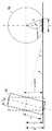
以下、図面を参照しつつ本発明を実施するための最良の形態について詳細に説明する。 図1は、本実施の形態に係るラック軸力演算方法が適用される車両操舵装置の概略構成を示す図である。 The best mode for carrying out the present invention will be described below in detail with reference to the drawings. FIG. 1 is a diagram showing a schematic configuration of a vehicle steering apparatus to which a rack axial force calculation method according to the present embodiment is applied.
車両操舵装置10において、ステアリングシャフト14は、運転者によって操作されるステアリングホイール12に連結されその回転が入力される入力軸14aと、ピニオン40へ回転を伝達する中間軸14bとに分割されている。入力軸14aと中間軸14bとは自在継手16で接続される。 In the
ラックハウジング50内には、車両の左右方向、すなわち車幅方向に延びるラックバー52が移動可能に収納されている。ピニオン40の両端は、軸受44によって回転可能に軸支される。ピニオン40は、ラックバー52の一部に形成されたラック42と噛合されている。自在継手16に接続された中間軸14bが回転すると、図示しないギヤを介してピニオン40が回転する。ラックバー52の両端には、それぞれタイロッド54の一端が接続される。タイロッド54の他端は、左右の操舵輪58を支持するナックルアーム56に連結されている。ナックルアーム56はキングピン60を支点として回転する。ステアリングホイール12が操作されてステアリングシャフト14が回転すると、この回転がピニオン40およびラック42によってラックバー52の車両左右方向の直線運動に変換される。この直線運動は、ナックルアーム56のキングピン60回りの回動に変換され、操舵輪58の転舵が行われる。 A
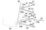
図2は、操舵輪の周辺の構成を概略的に示す図である。
操舵輪58は、いわゆるダブルジョイント式のサスペンション装置によって支持されている。すなわち、ナックルアーム56は、一対のアッパアーム61,62、一対のロアアーム63,64、タイロッド54などによって車体51に連結されている。アッパアーム61,62は、それぞれ車両幅方向に延設されていて、各内端にてゴムブッシュ61a,62aを介して車体51の一部に連結され、各外端にてボールジョイント61b,62bを介してナックルアーム56の上部に連結されている。一方、ロアアーム63,64は、それぞれ車両幅方向に延設されていて、各内端にてゴムブッシュ63a,64aを介して車体51の一部に連結され、各外端にてボールジョイント63b,64bを介してナックルアーム56の下部に連結されている。タイロッド54は、車両幅方向に延接され、その外端にてボールジョイント54aを介してナックルアーム56の中間部に連結され、内端にてボールジョイント54bを介してラックバー52に連結されている。FIG. 2 is a diagram schematically showing a configuration around a steered wheel.
The steered
このようなダブルジョイント式であることから、アッパアーム61,62およびロアアーム63,64は、各図中実線にて示す状態から操舵が行われると、キャンバ角の変化により図中破線に示すように変位する。すなわち、キングピン60の軸が図中太い一点鎖線にて示す状態から細い一点鎖線にて示す状態にその傾斜角度を変化させる。その結果、操舵輪58の振れまわりが大きくなり、タイヤの接地面が路面に引きずられる量が増え、その摩擦力によってラックバー52に負荷される軸線方向の力(ラック軸力)が大きくなる。このため、車両の設計においてはそのラック軸力がどの程度大きくなるかを正確に把握することが重要となる。 Because of such a double joint type, when the
このラック軸力は、通常は市販の機構解析ソフトを用いて求められたりするが、その演算においては一般にタイヤの摩擦は表現されない。つまり、いわゆるエアターンと呼ばれるように、便宜上摩擦のない路面上を剛体の車輪が操舵されると仮定し、キャンバ角等の変化により発生するキングピン軸周りを回転するタイヤの上下運動により生じるラック軸力が算出される。たとえば、キャンバ角等の変化により車輪が持ち上がるいわゆるジャッキアップにより生じるラック軸力が算出されることがあるが、タイヤの引きずりによる摩擦力の影響は考慮されていない。このため、実測値との整合がとれないという問題がある。そこで、本実施の形態では以下に述べるように、タイヤの引きずりを考慮した高精度なラック軸力の演算処理を行う。 The rack axial force is usually obtained by using commercially available mechanism analysis software, but the tire friction is generally not expressed in the calculation. In other words, the rack axial force generated by the vertical motion of the tire that rotates around the kingpin axis that occurs due to changes in camber angle, etc. Is calculated. For example, a rack axial force generated by so-called jack-up in which a wheel is lifted by a change in camber angle or the like may be calculated, but the influence of frictional force due to tire drag is not taken into consideration. For this reason, there is a problem that it is not possible to match the measured values. Therefore, in the present embodiment, as will be described below, highly accurate rack axial force calculation processing is performed in consideration of tire drag.
次に、本実施の形態に係るラック軸力演算方法の概要について説明する。
図3は、操舵による接地面の変化を表す説明図である。(A)はステアリングが切られていない直進時の状態を表し、(B)は右輪の内切時の状態を表し、(C)は右輪の外切時の状態を表している。図中の矢印は、タイヤの進行方向を表している。Next, an outline of the rack axial force calculation method according to the present embodiment will be described.
FIG. 3 is an explanatory diagram showing changes in the ground contact surface due to steering. (A) represents the state when the vehicle is traveling straight without steering, (B) represents the state when the right wheel is turned inward, and (C) shows the state when the right wheel is turned off. The arrow in the figure represents the traveling direction of the tire.
図3(A)に示すように、直進時においては、タイヤ70の接地面Aはほぼ長方形状となり、その幅方向および長手方向にほぼ均一な接地状態となる。ただし、キャンバ角によってタイヤ70が鉛直方向からややずれて接地するため、やや歪んだ形状にはなる。一方、図3(B)に示す内切時にはキャンバ角の変化によって接地面Aが内側に偏り、図3(C)に示す外切時には接地面Aが外側に偏る。すなわち、操舵によってタイヤ70の接地状態が図示のように変化し、その際、タイヤ70が路面との接地面Aにて引きずられる。本実施の形態では、このタイヤ70の引きずりを考慮してラック軸力の算出を行う。 As shown in FIG. 3A, when traveling straight, the ground contact surface A of the
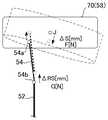
図4は、ラック軸力演算方法の概要を表す模式図である。
タイヤ70(同図は代表して右輪を示している)は、操舵によってラックバー52、タイロッド54が変位すると、点線のように転舵されてキャンバ角も変化する。このとき、タイヤ70の接地点Jも変位する。ラックバー52は、そのストロークによってタイロッド54を介して操舵輪58を回転させる仕事を行う。一方、タイヤ70は、操舵により接地面が引きずられると、摩擦による仕事を発生させる。ここでは、これらの仕事量を等価とおいてラック軸力を演算する。FIG. 4 is a schematic diagram showing an outline of a rack axial force calculation method.
When the
すなわち、マクロ的にみると、ラック軸力をG[N]、タイロッド54のストロークをRS[mm]とすると、ラックバー52による仕事量(エネルギー)E1は、下記式(1)のようになる。
E1=RS・G ・・・(1)
一方、接地点Jの引きずり量をS、接地点Jの荷重による力(垂直抗力)F、タイヤ70と路面との摩擦係数をμとすると、タイヤ70に負荷される摩擦による仕事量(エネルギー)E2は、下記式(2)のようになる。
E2=μ・F・S ・・・(2)
したがって、E1=E2として下記式(3)が成立する。
G=μ・F・S/RS ・・・(3)
ここで、摩擦係数μおよび引きずり力Fは車両重量やタイヤ70の特性から既知とすると、ラックストロークRSについてはたとえばセンサ等によって検出し、接地点Jの引きずり量Sを演算することにより、ラック軸力Gを算出することができる。That is, from a macro view, when the rack axial force is G [N] and the stroke of the
E1 = RS · G (1)
On the other hand, when the drag amount of the contact point J is S, the force (vertical drag) F due to the load of the contact point J, and the friction coefficient between the
E2 = μ · F · S (2)
Therefore, the following formula (3) is established with E1 = E2.
G = μ · F · S / RS (3)
Here, assuming that the friction coefficient μ and the drag force F are known from the vehicle weight and the characteristics of the
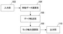
図5は、ラック軸力演算処理を行うラック軸力演算装置の概略を示すブロック図である。各ブロックは、ハードウェア的には、コンピュータのCPUやメモリをはじめとする素子や電気回路、機械装置で実現でき、ソフトウェア的にはコンピュータプログラム等によって実現されるが、ここでは、それらの連携によって実現される機能ブロックとして描いている。したがって、これらの機能ブロックはハードウェア、ソフトウェアの組合せによっていろいろなかたちで実現できることは、当業者には理解されるところである。 FIG. 5 is a block diagram showing an outline of a rack axial force calculation device that performs rack axial force calculation processing. Each block can be realized in hardware by an element such as a computer CPU and memory, an electric circuit, and a mechanical device. In software, it is realized by a computer program or the like. It is drawn as a functional block to be realized. Therefore, those skilled in the art will understand that these functional blocks can be realized in various forms by a combination of hardware and software.
本実施の形態のラック軸力演算装置は、入力部102、挙動データ演算部104、データ転送部106、ラック軸力演算部108、および出力部110を備える。
入力部102は、車両に搭載されたサスペンション装置の挙動計算に必要な各種入力情報を受け付ける。この入力情報はユーザにより入力される。挙動データ演算部104は、その入力情報に基づいてサスペンション装置の挙動計算を実行し、ラック軸力の計算に必要なパラメータを算出する。挙動データ演算部104による演算処理は、後述する公知の機構解析ソフトを用いることにより行われる。データ転送部106は、挙動データ演算部104により算出された結果データの一部をラック軸力演算部108へ転送する。ラック軸力演算部108は、転送された結果データを順次取り込んで後述するラック軸力演算方法に基づく処理を実行し、ラック軸力を演算する。出力部110は、ラック軸力演算部108による演算結果を必要に応じて画面等に出力する。The rack axial force calculation device according to the present embodiment includes an
The
次に、ラック軸力演算方法による具体的処理の流れについて説明する。
図6は、ラック軸力演算処理の流れを表すフローチャートである。図7〜図15は、そのラック軸力演算処理の過程を具体的に表す説明図である。以下、図6のフローチャートに基づき、図7〜図15の説明図を適宜参照しながら説明する。Next, a specific processing flow by the rack axial force calculation method will be described.
FIG. 6 is a flowchart showing the flow of the rack axial force calculation process. 7 to 15 are explanatory diagrams specifically showing the process of the rack axial force calculation process. Hereinafter, description will be made based on the flowchart of FIG. 6 with reference to the explanatory diagrams of FIGS.
まず、挙動データ演算部104は、ユーザの入力情報に基づき、操舵時のサスペンション装置の挙動計算を実行する(S10)。挙動データ演算部104は、たとえばADAMS(米国MSC社)等の市販の機構解析ソフト(自動車の設計/テスト専用のAdams/Carなど)を用いてその挙動計算を実行する。上述のように、このような機構解析ソフトについては公知であり当業者間においても多用されているため、その詳細な説明については省略する。ここでは、操舵輪58が設けられるサスペンションのボディ(車体)への取付点の位置情報や、フロントの車軸重量(FR軸重さ)、路面摩擦μ、比ストローク、タイヤの静荷重半径、直進時のタイヤの接地長・接地幅などのサスペンション構成部材の特性に関する情報を入力する。なお、各値は車両または車輪に固有の値であるので、入力が可能となっている。挙動データ演算部104は、その入力情報に基づいて公知の機構演算処理を行い、ラックストロークを所定の変化量で徐々に変化させたときの対応するトー角、キャンバ角、ナックルアーム56側の接地点Jの変位(詳しくは、接地長方向L、接地幅方向W、接地高さ方向Hのそれぞれの変位)、ラックストロークに基づき操舵輪58が持ち上がるいわゆるジャッキアップにより生じるラック軸力等を算出する。データ転送部106は、その演算結果をラック軸力演算部108へ出力する(S12)。 First, the behavior
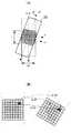
ラック軸力演算部108は、まず、タイヤ70の円柱モデルを想定してその路面との対向面についてタイヤ座標系を設定する(S14)。すなわち、図7(A)にタイヤの平面視を示すように、タイヤ70の接地点中心を原点として接地長Lの方向にX軸、接地幅Wの方向にY軸を規定した座標系を設定し、その対向面を各軸方向に1〜2mm間隔で区切って多数の微少要素に分割する。本実施の形態では、図8に示すように、X軸方向の正方向および負方向にそれぞれ150分割、Y軸方向の正方向および負方向にそれぞれ200分割の微少要素(図中斜線部にてその1つを例示)が定義されている。なお、図7(B)にタイヤの背面視を示すように、タイヤ70には車両重量等に伴う鉛直方向の荷重が負荷されるため、その静荷重半径r(タイヤの軸中心から路面までの距離)は、荷重がない場合の無負荷半径Rよりも小さくなる。無負荷半径Rは、静荷重半径r、直進時の接地長Lにより、下記式(4)から算出することができる。
R=L/2/cos(atan(2・L/r))) ・・・(4)The rack axial
R = L / 2 / cos (atan (2.L / r))) (4)
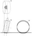
続いて、ラック軸力演算部108は、操舵時のキャンバ角の変化に応じたタイヤ70の接地範囲を演算する(S16)。図9には、左上段にタイヤ概形の平面視が示され、左下段に背面視が示され、さらに右下段に側面視が示されている。タイヤ70がその直進方向から操舵されると、背面視において点線で示す状態から実線にて示す状態に変化する。すなわち、キャンバ角θが変化し、それに伴ってタイヤ70の接地面の形状も変化する。背面視に太線にて示されるようにタイヤ70の接地幅が変化するとともに、側面視に太線にて示されるように接地長も変化する。タイヤ70の接地範囲は、このようなキャンバ角θの変化に伴うタイヤ70の幾何学的形状から求めることができる。 Subsequently, the rack axial
図10の左段に背面視を示すように、タイヤ70のキャンバ角θが変化すると、一点鎖線にて示すタイヤ70の回転軸から路面gまでの距離mは、下記式(5)のようになる。ここで、wはタイヤの半幅(幅の1/2)を表し、Rは上述した無負荷半径R、rはタイヤ静荷重半径を表している。 When the camber angle θ of the
m=(r+w・sinθ)/cosθ ・・・(5)
このため、タイヤ70においてm>Rの箇所は接地長L=0となる。一方、m≦Rの箇所はその接地長Lが下記式(6)にて表される。
L=2・m/(tan(asin(m/R))) ・・・(6)
このようにして、タイヤ70の接地幅方向に沿って上記微少要素の間隔おきに接地長Lが算出されると、各微少要素のうち接地面を構成する接地面構成要素が求まる。たとえば、Y軸方向に沿って各微少要素の間隔ごとに算出された接地長Lの2等分して、それをX軸の正負に振り分けた座標に相当する微少要素を接地面構成要素とすることができる。このような演算を、表計算等によりラックストロークRSを所定刻みΔRSで変化させつつ逐次行う。m = (r + w · sinθ) / cosθ (5)
For this reason, in the
L = 2 · m / (tan (asin (m / R))) (6)
In this way, when the ground contact length L is calculated at intervals of the minute elements along the ground contact width direction of the
図11には、この接地長の演算を表計算にて行った結果が示されている。同図の横軸はタイヤ70の幅方向の座標Yを表し、縦軸はラックストロークRSごとのキャンバ角θを表している。図の太枠内部には接地長L[mm]の演算結果が表示されている。これにより、ラックストロークRSが変化するごとに、つまりキャンバ角θが変化するごとに、各接地幅位置の接地長Lが変化していることが分かる。つまり、接地面が変化していることが分かる。 FIG. 11 shows the result of performing the calculation of the contact length by a table calculation. In the drawing, the horizontal axis represents the coordinate Y in the width direction of the
ラック軸力演算部108は、この接地幅位置と接地長Lとの関係から、各ラックストロークRS位置における接地面位置、つまり接地面構成要素の座標を求めることができる。あるラックストロークRS位置における接地面を座標軸(X,Y)に沿った画面に表示すると、図12のようになる。同図では、横軸がY座標、縦軸がX座標を表しており、接地面を構成する微少要素、つまり接地面構成要素についてのみ、その接地長Lを表記している。その結果、図示の全体がタイヤ70の対向面を表すが、濃色部分が接地面を表している。 The rack axial
ラック軸力演算部108は、以上のようにして算出された各接地面構成要素について、図13に示すトー方向への(回転方向の)座標変換を行う(S18)。操舵によるタイヤ70の転舵によって接地面が回転するためである。各接地面構成要素についてこの座標変換前の座標を(X,Y)、座標変換後の座標を(X’,Y’)とすると、下記式(7)が成立する。 The rack axial

ラック軸力演算部108は、続いて、各接地面構成要素の軌跡から図14に示す並進方向の座標変換を行う(S20)。この並進方向への座標変換は、図示のように車体を基準としたその直進方向を座標Lにて表し、これと直角な方向を座標Wにて表す。このとき、変換後の座標(L,W)について、下記式(8)および(9)が成立する。
L=X’+接地面構成要素の座標L ・・・(8)
W=Y’+接地面構成要素の座標W ・・・(9)
ラック軸力演算部108は、続いて接地面の移動のエネルギー、つまり各接地面構成要素の移動による仕事量の総和を演算する(S22)。すなわち、図15(A)に示すように、操舵によるラックバー52のストロークによりタイヤ70が転舵角αだけ回転すると、同図(B)に示すように、各接地面構成要素はその回転および並進を伴って移動量ΔSだけ移動する。つまり、仮にラックストロークRSがRS1からRS2に変化したときに、ある接地面構成要素の座標が(L1,W1)から(L2,W2)へ移動したとすると、ラックストロークの刻みΔRSは、下記式(10)のようになる。
ΔRS=(RS2−RS1) ・・・(10)
また、接地面構成要素の移動量ΔSは、下記式(11)のようになる。
ΔS={(L2−L1)2+(W2−W1)2}1/2 ・・・(11)
ここで、フロントの車軸重量F、路面摩擦μ、接地している接地面構成要素の個数Nとすると、各接地面構成要素の接地荷重ΔFは、下記式(12)のように表される。
ΔF=(F/2)/N ・・・(12)
したがって、各接地面構成要素の移動による仕事量の総和Eは、上記式(2)に基づき下記式(13)のようになる。
E=Σ(μ・ΔF・ΔS) ・・・(13)
ここで、接地面構成要素が移動前後で接地状態を維持する場合には、上記式(13)において演算される仕事量の演算に含まれる(たとえば図15(B)のΔS:ΔS2のときなど)。一方、接地面構成要素が移動前後で接地しなくなる、あるいは、新たに接地する場合には、上記式(13)において演算されない(たとえば図15(B)のΔS:ΔS1,ΔS3のときなど)。
ラック軸力演算部108は、以上の演算結果を用いてラック軸力Gを演算する(S24)。すなわち、上記式(3)から、各接地面構成要素による微少ラック軸力ΔGは、下記式(14)のようになる。
ΔG=μ・ΔF・ΔS/ΔRS ・・・(14)Subsequently, the rack axial
L = X ′ + coordinate L of the ground plane component (8)
W = Y ′ + coordinate W of the ground plane component (9)
The rack axial
ΔRS = (RS2−RS1) (10)
Further, the movement amount ΔS of the ground plane component is expressed by the following equation (11).
ΔS = {(L2−L1)2 + (W2−W1)2 }1/2 (11)
Here, if the front axle weight F, the road surface friction μ, and the number N of grounded ground plane components, the ground load ΔF of each ground plane component is expressed by the following equation (12).
ΔF = (F / 2) / N (12)
Therefore, the total amount E of work due to the movement of each ground plane component is expressed by the following equation (13) based on the above equation (2).
E = Σ (μ · ΔF · ΔS) (13)
Here, when the ground contact surface component maintains the ground contact state before and after the movement, it is included in the calculation of the work amount calculated in the above equation (13) (for example, when ΔS: ΔS2 in FIG. 15B). ). On the other hand, when the ground plane component is not grounded before and after the movement, or is newly grounded, it is not calculated in the above equation (13) (for example, ΔS: ΔS1, ΔS3 in FIG. 15B).
The rack axial
ΔG = μ · ΔF · ΔS / ΔRS (14)
したがって、タイヤの引きずりによるトータルのラック軸力Gは、下記式(15)を表計算することにより算出される。
G=ΣΔG=Σ(μ・ΔF・ΔS/ΔRS) ・・・(15)
そして、上記式(14)にて算出されたラック軸力Gと、S10にて得られたジャッキアップ分によるラック軸力とを加算することにより、最終的に実測値と整合するラック軸力が得られる。Therefore, the total rack axial force G due to tire drag is calculated by spreadsheet calculation of the following equation (15).
G = ΣΔG = Σ (μ · ΔF · ΔS / ΔRS) (15)
Then, by adding the rack axial force G calculated by the above equation (14) and the rack axial force due to the jack-up obtained in S10, the rack axial force that finally matches the actually measured value is obtained. can get.
以上に説明したように、操舵によるタイヤ70の引きずりによる仕事量(エネルギー収支)を考慮してラックバー52の軸力が算出される。このため、一般の機構解析のようにタイヤ70の摩擦を考慮しない演算方法よりも高精度で実測値に整合した演算結果を得ることができる。 As described above, the axial force of the
本発明は上述の実施の形態に限定されるものではなく、当業者の知識に基づいて各種の設計変更等の変形を実施の形態に対して加えることも可能であり、そのような変形が加えられた実施の形態も本発明の範囲に含まれうる。 The present invention is not limited to the above-described embodiments, and various modifications such as design changes can be added to the embodiments based on the knowledge of those skilled in the art. The described embodiments can also be included in the scope of the present invention.
上記実施の形態では、ラックバー52に負荷されるラック軸力そのものを演算する例を示した。変形例においては、実質的にラック軸力と等価とみなされるタイロッド54等の軸力を演算し、これをラック軸力としてもよい。
上記実施の形態では、ラックアンドピニオン式の操舵装置について言及したが、リサーキュレーティング・ボール式の操舵装置において、ラック軸力に相当するタイヤをキングピン軸周りに旋回させる力を演算するものに適用してもよい。In the above embodiment, an example in which the rack axial force itself applied to the
In the above embodiment, the rack-and-pinion type steering device has been described. However, in the recirculating ball type steering device, the present invention is applied to a device that calculates a force for turning the tire corresponding to the rack axial force around the kingpin axis. May be.
上記実施の形態では、いわゆるダブルジョイント式のサスペンション装置を搭載した車両についてラック軸力を算出する例を示した。変形例においては、本発明のラック軸力演算方法を、いわゆるシングルジョイント式その他の形式のサスペンション装置を搭載した車両について適用してもよい。ただし、シングルジョイント式のサスペンション装置によれば、操舵時においてキングピンの軸の変位量が少ないため、タイヤの引きずり量も小さい。言い換えれば、操舵時においてキングピンの軸の変位量が大きくなるダブルジョイント式のサスペンション装置のほうがタイヤの引きずり量が大きくなるため、本発明の適用の効果はより大きくなると言える。 In the embodiment described above, an example in which the rack axial force is calculated for a vehicle on which a so-called double joint type suspension device is mounted has been shown. In a modification, the rack axial force calculation method of the present invention may be applied to a vehicle equipped with a so-called single joint type or other type of suspension device. However, according to the single joint type suspension device, the amount of tire drag is small because the amount of displacement of the kingpin shaft is small during steering. In other words, it can be said that the effect of the application of the present invention becomes larger in the double joint type suspension device in which the displacement amount of the shaft of the kingpin becomes larger during steering because the drag amount of the tire becomes larger.
10 車両操舵装置、 12 ステアリングホイール、 14 ステアリングシャフト、 40 ピニオン、 42 ラック、 51 車体、 52 ラックバー、 54 タイロッド、 56 ナックルアーム、 58 操舵輪、 60 キングピン、 61,62 アッパアーム、 63,64 ロアアーム、 70 タイヤ、 102 入力部、 104 挙動データ演算部、 106 データ転送部、 108 ラック軸力演算部、 110 出力部。 DESCRIPTION OF
Claims (3)
Translated fromJapanese前記操舵に伴うキャンバ角の変化に基づいて、前記操舵輪を構成するタイヤの接地面の変化量を演算する接地面演算工程と、
前記接地面に加わる摩擦力および前記接地面の変化量に基づいて、前記操舵により前記タイヤになされた摩擦による仕事量を演算する仕事量演算工程と、
前記操舵による前記ラックバーの変位量を取得する変位量取得工程と、
前記摩擦による仕事量および前記ラックバーの変位量に基づいて、前記ラックバーに作用する軸力を算出する軸力算出工程と、
を備えたことを特徴とするラック軸力演算方法。In a rack steering force calculation method for calculating the axial force acting on the rack bar, for a vehicle steering apparatus that converts the rotational movement of the steering wheel by steering into the linear movement of the rack bar to steer the steering wheel,
Based on a change in camber angle accompanying the steering, a contact surface calculation step for calculating a change amount of a contact surface of a tire constituting the steered wheel;
Based on the frictional force applied to the contact surface and the amount of change of the contact surface, a work amount calculating step for calculating the work amount due to the friction applied to the tire by the steering,
A displacement amount acquisition step of acquiring a displacement amount of the rack bar by the steering;
An axial force calculation step of calculating an axial force acting on the rack bar based on the work amount due to the friction and the displacement amount of the rack bar;
A rack axial force calculation method comprising:
前記タイヤの路面との対向面について予め設定した座標系を基準に、その対向面を複数の微少要素に分割する要素分割工程と、
前記キャンバ角の変化に基づいて、各微少要素のうち前記接地面を構成する接地面構成要素を演算する要素演算工程と、
を含み、
前記仕事量演算工程は、
前記操舵による各接地面構成要素の移動量を演算する移動量演算工程と、
各接地面構成要素に加わる摩擦力と各接地面構成要素の移動量とを乗算して得られる微少仕事量の総和を前記仕事量として算出する仕事量算出工程と、
を含むことを特徴とする請求項1に記載のラック軸力演算方法。The ground plane calculation step includes:
An element dividing step for dividing the facing surface into a plurality of minute elements on the basis of a preset coordinate system for the facing surface with the road surface of the tire,
Based on the change of the camber angle, an element calculation step of calculating a ground plane constituent element that constitutes the ground plane among the micro elements, and
Including
The workload calculation step includes:
A movement amount calculating step for calculating a movement amount of each ground plane component by the steering;
A work amount calculating step of calculating a sum of minute work amounts obtained by multiplying the frictional force applied to each ground plane component and the amount of movement of each ground plane component as the work amount;
The rack axial force calculation method according to claim 1, further comprising:
Priority Applications (1)
| Application Number | Priority Date | Filing Date | Title |
|---|---|---|---|
| JP2007144228AJP5145772B2 (en) | 2007-05-30 | 2007-05-30 | Rack axial force calculation method |
Applications Claiming Priority (1)
| Application Number | Priority Date | Filing Date | Title |
|---|---|---|---|
| JP2007144228AJP5145772B2 (en) | 2007-05-30 | 2007-05-30 | Rack axial force calculation method |
Publications (2)
| Publication Number | Publication Date |
|---|---|
| JP2008296715A JP2008296715A (en) | 2008-12-11 |
| JP5145772B2true JP5145772B2 (en) | 2013-02-20 |
Family
ID=40170641
Family Applications (1)
| Application Number | Title | Priority Date | Filing Date |
|---|---|---|---|
| JP2007144228AExpired - Fee RelatedJP5145772B2 (en) | 2007-05-30 | 2007-05-30 | Rack axial force calculation method |
Country Status (1)
| Country | Link |
|---|---|
| JP (1) | JP5145772B2 (en) |
Families Citing this family (3)
| Publication number | Priority date | Publication date | Assignee | Title |
|---|---|---|---|---|
| JP5799577B2 (en)* | 2011-05-16 | 2015-10-28 | 日産自動車株式会社 | Vehicle steering apparatus, steering force estimation apparatus, steering control method, and steering force estimation method |
| JP5799578B2 (en)* | 2011-05-16 | 2015-10-28 | 日産自動車株式会社 | Vehicle steering apparatus and steering control method |
| JP6458584B2 (en)* | 2015-03-23 | 2019-01-30 | スズキ株式会社 | Moment analysis device for vehicle, moment analysis method for vehicle, and moment analysis program for vehicle |
- 2007
- 2007-05-30JPJP2007144228Apatent/JP5145772B2/ennot_activeExpired - Fee Related
Also Published As
| Publication number | Publication date |
|---|---|
| JP2008296715A (en) | 2008-12-11 |
Similar Documents
| Publication | Publication Date | Title |
|---|---|---|
| CN100528665C (en) | Turning radius calculation method | |
| US7779544B2 (en) | Method and device for adjusting the steering wheel of a motor vehicle | |
| JP5995040B2 (en) | Road surface friction coefficient estimating apparatus and method | |
| JP5293814B2 (en) | Sensor offset estimation device | |
| CN110720032A (en) | Method and system for dynamometer testing of motor vehicles | |
| JP5439784B2 (en) | Vehicle control device | |
| JP7413895B2 (en) | Road surface μ estimation device | |
| Mántaras et al. | Virtual test rig to improve the design and optimisation process of the vehicle steering and suspension systems | |
| JP5145772B2 (en) | Rack axial force calculation method | |
| JP5045244B2 (en) | Tire behavior calculation method | |
| CN1592842A (en) | Method and system for determining symmetry and ackermann geometry status of the steering system of a vehicle | |
| CN114954492B (en) | A vehicle dynamic wheel load measurement and driving safety assistance system | |
| JP5569355B2 (en) | Suspension behavior estimation method | |
| JP2019084839A (en) | Detection device, ball joint, steering gear box | |
| Cho | Vehicle steering returnability with maximum steering wheel angle at low speeds | |
| JP4314142B2 (en) | Steering wheel rotation test equipment | |
| CN111412886B (en) | Detection method and detection system | |
| JP5154226B2 (en) | Device for determining vehicle wheel alignment | |
| JP5218019B2 (en) | Wheel alignment measuring device | |
| US20060101656A1 (en) | Wheel position sensor | |
| CN112977615B (en) | Steering shaft assembly and vehicle | |
| JP3743937B2 (en) | Modeling method of steering system for automobile | |
| JP2015187568A (en) | Vehicle moment analysis device, vehicle moment analysis method, and vehicle moment analysis program | |
| JP3547806B2 (en) | Vehicle steering characteristic control method | |
| Klaps et al. | Steering drift and wheel movement during braking: Static and dynamic measurements |
Legal Events
| Date | Code | Title | Description |
|---|---|---|---|
| A621 | Written request for application examination | Free format text:JAPANESE INTERMEDIATE CODE: A621 Effective date:20100115 | |
| TRDD | Decision of grant or rejection written | ||
| A01 | Written decision to grant a patent or to grant a registration (utility model) | Free format text:JAPANESE INTERMEDIATE CODE: A01 Effective date:20121030 | |
| A61 | First payment of annual fees (during grant procedure) | Free format text:JAPANESE INTERMEDIATE CODE: A61 Effective date:20121112 | |
| FPAY | Renewal fee payment (event date is renewal date of database) | Free format text:PAYMENT UNTIL: 20151207 Year of fee payment:3 | |
| LAPS | Cancellation because of no payment of annual fees |