JP5141640B2 - Automated driving equipment system - Google Patents
Automated driving equipment systemDownload PDFInfo
- Publication number
- JP5141640B2 JP5141640B2JP2009132750AJP2009132750AJP5141640B2JP 5141640 B2JP5141640 B2JP 5141640B2JP 2009132750 AJP2009132750 AJP 2009132750AJP 2009132750 AJP2009132750 AJP 2009132750AJP 5141640 B2JP5141640 B2JP 5141640B2
- Authority
- JP
- Japan
- Prior art keywords
- key
- monitoring
- total number
- entry
- keys
- Prior art date
- Legal status (The legal status is an assumption and is not a legal conclusion. Google has not performed a legal analysis and makes no representation as to the accuracy of the status listed.)
- Active
Links
- 238000012544monitoring processMethods0.000claims9
- 230000004888barrier functionEffects0.000claims1
- 238000009434installationMethods0.000claims1
- 238000002360preparation methodMethods0.000claims1
Images


Landscapes
- Refuge Islands, Traffic Blockers, Or Guard Fence (AREA)
- Warehouses Or Storage Devices (AREA)
Description
Translated fromJapanese本発明は、自動運転機器システム、特に、自動運転機器の周囲を進入防護柵で囲い、進入防護柵の一部に複数の進入扉を設けた自動運転機器システムに関する。 The present invention relates to an automatic driving equipment system, and more particularly, to an automatic driving equipment system in which an automatic driving equipment is surrounded by an entrance protection fence and a plurality of entrance doors are provided in a part of the entrance protection fence.
従来から、自動倉庫や搬送車システム等の自動運転機器システムでは、スタッカークレーンや搬送車の走行路内に無断で人が進入できないように、進入防護柵が囲設される。このような進入防護柵の一部には、修理や保守点検を行う作業員等が進入防護柵内に進入できるように進入扉が設けられる(例えば、特許文献1を参照。)。 2. Description of the Related Art Conventionally, in automatic operation equipment systems such as an automatic warehouse and a transport vehicle system, an approach protection fence is enclosed so that a person cannot enter the stacker crane or the travel path of the transport vehicle without permission. An entrance door is provided in a part of such an entry protection fence so that an operator or the like who performs repair or maintenance inspection can enter the entry protection fence (see, for example, Patent Document 1).
上記従来の自動運転機器システムでは、走行路のレイアウトによっては、他の設備を分断してしまう場合がある。このような場合には、走行路によって分断された設備間を往来するために、走行路を迂回して遠回りする設備運用や走行路を横断するための歩行帯や階段等の付帯設備の設置が必要となる。 In the conventional automatic driving apparatus system, other equipment may be divided depending on the layout of the traveling path. In such a case, in order to travel between the facilities separated by the traveling road, the equipment operation detouring around the traveling road and the installation of auxiliary equipment such as walking zones and stairs for crossing the traveling road are required. Necessary.
しかし、このような設備運用や付帯設備の設置は、使い勝手の悪化やコストアップを生じさせるため、進入扉を通じて進入防護柵内の通り抜けを可能にしたいという要望がある。 However, there is a demand for enabling the passage through the entrance protection fence through the entrance door because such facility operation and installation of incidental facilities cause usability deterioration and cost increase.
本発明の課題は、自動運転機器の周囲を進入防護柵で囲い、進入防護柵の一部に複数の進入扉を設けた自動運転機器システムにおいて、進入防護柵内における進入者の安全を確保しつつ、進入扉を通じて進入防護柵内の通り抜けを可能にすることにある。 An object of the present invention is to secure the safety of an intruder in an entrance protection fence in an automated operation equipment system in which an autonomous protection device is surrounded by an entrance protection fence and a plurality of entrance doors are provided in a part of the entrance protection fence. On the other hand, it is possible to pass through the entrance protection fence through the entrance door.
本発明にかかる自動運転機器システムは、自動運転機器の周囲を進入防護柵で囲い、進入防護柵の一部に複数の進入扉を設けた自動運転機器システムであって、進入防護柵の外側に設けられた複数のキー装着部と、進入者把握装置とを備えている。進入者把握装置は、キー装着部に装着されている監視キーの総数を把握するとともに、この監視キーの総数と予め記憶されている監視キーの総数とを比較する。そして、把握した監視キーの総数と予め記憶されている監視キーの総数が異なる場合には、自動運転機器の動作を制限させる。
この自動運転機器システムでは、進入防護柵内への進入者の有無の判定を行い、進入防護柵内への進入者がいると判定された場合には、自動運転機器の動作を制限することができる。したがって、進入防護柵内における進入者の安全を確保しつつ、進入扉を通じて進入防護柵内の通り抜けを可能にすることができる。An automatic driving device system according to the present invention is an automatic driving device system in which an autonomous driving device is surrounded by an approach protection fence and a plurality of entrance doors are provided in a part of the approach protection fence. A plurality of key mounting portions provided and an intruder grasping device are provided. The intruder grasping device grasps the total number of monitoring keys attached to the key attaching unit, and compares the total number of monitoring keys with the total number of monitoring keys stored in advance. Then, when the grasped total number of monitoring keys is different from the total number of monitoring keys stored in advance, the operation of the automatic driving device is restricted.
In this automatic driving equipment system, it is judged whether there is an intruder in the entry protection fence, and if it is judged that there is an intruder in the entry protection fence, the operation of the automatic driving equipment may be restricted. it can. Therefore, it is possible to pass through the entry protection fence through the entry door while ensuring the safety of the intruder in the entry protection fence.
複数のキー装着部は、各進入扉に対応して設けられていてもよい。 The plurality of key mounting portions may be provided corresponding to each entry door.
各進入扉には、施錠機構が設けられており、施錠機構を解錠する施錠キーは、監視キーと連結、一体化又は共通化されていてもよい。
この自動運転機器システムでは、進入防護柵内への進入者が進入扉を開ける際に、進入者が監視キーを持った状態にすることができるため、監視キーを持たないで進入者が進入防護柵内に進入することを確実に防ぐことができる。Each entrance door is provided with a locking mechanism, and a locking key for unlocking the locking mechanism may be connected to, integrated with, or shared with the monitoring key.
In this autonomous driving equipment system, when an intruder enters the entrance protection fence, the intruder can have a monitoring key when opening the entrance door. It is possible to reliably prevent entry into the fence.
キー装着部は、進入防護柵の外側からのみ監視キーの装着が可能になっていてもよい。
この自動運転機器システムでは、進入防護柵内から進入者が監視キーをキー装着部に装着することができないため、監視キーがキー装着部に装着されている場合には、進入防護柵内に進入者がいない状態を確保することができる。The key mounting portion may be capable of mounting the monitoring key only from the outside of the entry protection fence.
In this automatic driving equipment system, since the intruder cannot attach the monitoring key to the key attachment part from inside the entry protection fence, when the monitoring key is attached to the key attachment part, it enters the entry protection fence. It is possible to ensure that no one is present.
把握した監視キーの総数と予め記憶されている監視キーの総数が異なる場合において自動運転機器を起動するための指令が行われたときには、把握した監視キーの総数と予め記憶されている監視キーの総数が異なることを報知するようにしてもよい。
この自動運転機器システムでは、自動運転機器を起動できない理由を明確にできるため、進入者に対して進入防護柵外へ退出することを促すことができる。When the command for starting the automatic operation device is issued when the total number of monitored keys is different from the total number of monitored keys stored in advance, the total number of monitored keys and the number of monitored keys stored in advance are You may make it alert | report that a total number differs.
In this automatic driving equipment system, since the reason why the automatic driving equipment cannot be activated can be clarified, it is possible to urge the intruder to leave the entrance protection fence.
本発明にかかる自動運転機器システムでは、進入防護柵内における進入者の安全を確保しつつ、進入扉を通じて進入防護柵内の通り抜けを可能にすることができる。 In the automatic driving equipment system according to the present invention, it is possible to pass through the entry protection fence through the entry door while ensuring the safety of the intruder in the entry protection fence.
(1)搬送車システムの基本構成
図1は、本発明にかかる自動運転機器システムの一実施形態としての搬送車システム1のレイアウト図である。搬送車システム1は、走行路2上に搬送車3を走行させるためのシステムである。搬送車3は、走行路2上を走行し、制御系10(後述)の搬送指令にしたがって、目的のステーション8から物品を積み込み、次に搬送先のステーション8の場所まで走行して物品を搬送先のステーション8に積み出す。(1) Basic Configuration of Transport Vehicle System FIG. 1 is a layout diagram of a
走行路2の両側には、走行路2内に無断で人が進入できないようにするための進入防護柵31が設けられており、その内側が、自動運転機器としての走行路2及び搬送車3の周囲を囲む離隔エリア32になっている。進入防護柵31は、人が簡単には乗り越えられない程度の高さを有している。 On both sides of the
進入防護柵31の一部には、所定の箇所(ここでは、4カ所)に進入口33及び進入扉34が設けられており、修理や保守点検を行う際に、人が進入防護柵31内に進入できるようになっている。
なお、搬送車3の種類は、本実施形態のような走行路2上を走行する有軌道台車であってもよいし、無軌道で走行する無人搬送車であってもよい。A part of the
Note that the type of the
(2)搬送車システムの基本制御系及び基本動作
図2は、搬送車システム1の制御系10を示すブロック図である。制御系10は、基本的には、メインコントロールボックス21と、搬送車3と、給電スイッチボックス22と、ローカルコントロールボックス23とが通信可能に接続されることによって構成されている。(2) Basic Control System and Basic Operation of Transport Vehicle System FIG. 2 is a block diagram showing the
メインコントロールボックス21は、主として、メイン制御装置21aを有している。メイン制御装置21aは、給電スイッチボックス22に対して搬送車3への給電指令や給電遮断指令を行い、また、搬送車3に対して搬送指令や搬送停止指令を行うための装置である。 The
給電スイッチボックス22は、電源回路22aを有している。電源回路22aは、メインコントロールボックス21からの給電指令や給電遮断指令にしたがって搬送車3への給電や給電遮断を行うための装置である。また、給電スイッチボックス22は、メンテナンスのために、自動運転(後述)停止中に、手動操作で搬送車3への給電を行うことができる。そして、このような給電の切り換えの際には、監視キー25(後述)が共通のキーとして使用される。 The power
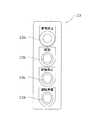
図3は、ローカルコントロールボックス23の要部を示す図である。ローカルコントロールボックス23は、各進入扉34に設けられている。ここでは、ローカルコントロールボックス23は、進入防護柵31の外側で、かつ、進入扉34の近傍に自立設置されている。 FIG. 3 is a diagram showing a main part of the
ローカルコントロールボックス23には、非常停止ボタン23aと、起動ボタン23bと、自動停止ボタン23cと、運転準備ボタン23dとが設けられている。各ボタン23a〜23dには、搬送車システム1の運転状態を表示するための表示ランプが一体的に設けられている。 The
運転準備ボタン23dは、メイン制御装置21aに給電指令を行わせるためのボタンであり、運転準備ボタン23dを押すと、メイン制御装置21aから給電スイッチボックス22へ給電指令がなされて搬送車3への給電が開始されるようになっている。そして、搬送車3への給電が開始されると、運転準備ボタン23dの表示ランプが点灯し、起動ボタン23bの表示ボタンが点滅するようになっている。 The
起動ボタン23bは、搬送車3への給電が行われていることを前提として、メイン制御装置21aに搬送指令を行わせるためのボタンである。起動ボタン23bを押すと、メイン制御装置21aから搬送車3へ搬送指令がなされて搬送車3の自動運転が開始されるようになっている。そして、搬送車3の自動運転が開始されると、起動ボタン23bの表示ランプが点滅状態から点灯状態に変わるようになっている。 The
ここで、自動運転とは、メイン制御装置21aからの搬送指令にしたがって、物品を搬送先のステーション8に積み出すといった、メイン制御装置21aに予め設定されている一連の走行動作を自動的に繰り返す運転である。一連の走行動作は、目的のステーション8から物品を搬送車3に積み込み、次に搬送先のステーション8の場所まで搬送車3を走行させることを含んでいる。 Here, the automatic operation automatically repeats a series of traveling operations set in advance in the main control device 21a, such as loading articles to the
自動停止ボタン23cは、メイン制御装置21aに搬送停止指令を行わせるためのボタンであり、自動停止ボタン23cを押すと、メイン制御装置21aから搬送車3へ搬送停止指令がなされて搬送車3が自動運転の基準位置まで移動して停止するようになっている。そして、この自動運転の停止処理が行われている間だけ自動停止ボタン23cの表示ランプが点灯し、自動運転の停止処理が完了した後は、起動ボタン23bの表示ランプが点灯状態から点滅状態に変わるようになっている。 The
非常停止ボタン23aは、不測の事態に搬送車システム1を緊急停止させるためのボタンである。 The
このような搬送車システム1では、給電を開始する際には、人が運転準備ボタン23dを押すことによって、搬送車3への給電が開始される。そして、給電が行われている状態から自動運転を開始する際には、人が起動ボタン23bを押すことによって、自動運転が開始される。また、自動運転が行われている状態から自動運転を停止する際には、人が自動停止ボタン23cを押すことによって、自動運転が停止される。 In such a
(3)進入防護柵内の通り抜け時の安全確保機能に関する構成及び動作
ところで、このような搬送車システム1が設置された工場等においては、搬送車システム1の走行路2が他の設備を分断してしまう場合がある。このような場合に、走行路2を迂回して遠回りをする設備運用や走行路2を横断するための歩行帯や階段等の付帯設備の設置を行うことなく、走行路2によって分断された設備間を往来したいという要望がある。(3) Configuration and operation regarding safety ensuring function at the time of passing through the entrance protection fence By the way, in a factory or the like where the
しかし、進入扉34を開けて進入防護柵31内に人が進入して進入防護柵31内を通り抜ける行為は、非常に危険な行為である。例えば、ある人が自動停止ボタン23cを押すことによって、自動運転を停止させた状態にして進入防護柵31内に進入したとする。この場合は、他の人が、進入防護柵31内に人が進入していることを認識しないままで、起動ボタン23bを押して自動運転を開始させてしまうおそれがある。このため、上記の要望を実現するためには、進入防護柵31内の通り抜け時において、進入防護柵31内への進入者の安全が確保される必要がある。 However, an act of opening the
<安全確保機能に関する構成>
そこで、この搬送車システム1には、以下の安全確保機能が設けられている。安全確保機能は、最初に、進入防護柵31内への進入者の有無を判定する機能を含んでいる。安全確保機能は、さらに、進入防護柵31内への進入者がいると判定された場合には、搬送車3の動作を制限して、進入防護柵31内における進入者の安全を確保しつつ、進入扉34を通じて進入防護柵31内の通り抜けを可能にする機能を含んでいる。以下、この安全確保機能に関する構成について説明する。<Configuration related to safety ensuring function>
Therefore, the
搬送車システム1には、通り抜け監視ボックス24がさらに設けられており、メインコントロールボックス21に通信可能に接続されることで制御系10を構成している。図4は、通り抜け監視ボックス24の要部を示す図である。通り抜け監視ボックス24は、各進入扉34に対応して設けられている。ここでは、各通り抜け監視ボックス24は、進入防護柵31の外側で、かつ、進入扉34の近傍に自立設置されている。 The
通り抜け監視ボックス24には、複数(ここでは、8個)のキー装着部24a〜24hが設けられている。各キー装着部24a〜24hには、監視キー25が装着できるようになっている。ここでは、各キー装着部24a〜24hには、キー穴が形成されている。このキー穴に監視キー25を挿入して右に回すことでキー穴から監視キー25を抜くことができないように、また、右に回された監視キー25を左に回すことでキー穴から監視キー25をキー穴から抜くことができるように構成されている。監視キー25は、複数(ここでは、4個)の通り抜け監視ボックス24のキー装着部24a〜24hの全数(ここでは、32個)よりも少ない数(ここでは、16個)だけ準備されている。なお、図4では、キー装着部24a〜24hのうちキー装着部24e〜24hのみに監視キー25が装着された状態が図示されている。 The pass-through
ここで、複数(ここでは、16個)の監視キー25は、全て同じキー形状を有している。また、複数(ここでは、4個)の通り抜け監視ボックス24の複数(ここでは、8個)のキー装着部24a〜24bも、監視キー25に適合するキー穴を有している。 Here, the plurality (16 in this case) of the
そして、各通り抜け監視ボックス24は、監視キー25がキー装着部24a〜24hに装着された状態であるか否かを電気的に検知できるようになっており、このような検知信号をメインコントロールボックス21へ送信するようになっている。 Each passing-through
また、キー装着部24a〜24hは、進入防護柵31内からでは人の手が届かないように配置される等によって、進入防護柵31の外側からのみ監視キー25の装着が可能になっている。 Further, the
メインコントロールボックス21には、上記のメイン制御装置21aの他に、進入者把握装置21bがさらに設けられている。進入者把握装置21bは、各通り抜け監視ボックス24からメインコントロールボックス21が受信した検知信号に基づいて、複数の進入扉34のキー装着部24a〜24hに装着されている監視キー25の総数を把握する。検知信号は、監視キー25がキー装着部24a〜24hに装着された状態であるか否かの検知信号である。進入者把握装置21bは、さらに、この監視キー25の総数と予め記憶されている監視キー25の総数(ここでは、16個)とを比較する。そして、把握した監視キー25の総数と予め記憶されている監視キー25の総数が異なる場合には、進入者把握装置21bは、メイン制御装置21aに対して、搬送車3の動作を制限するように運転制限指令を行うようになっている。 In addition to the main control device 21a, the
そして、メイン制御装置21aは、この運転制限指令を受けて、自動運転が行われている場合には、自動運転を強制的に停止させ、起動ボタン23bを押しても、その指令を受け付けずに自動運転を開始しない状態にする。メイン制御装置21aは、また、自動運転が行われていない場合や給電が行われていない場合には、起動ボタン23bや運転準備ボタン23dを押しても、その指令を受け付けずに自動運転や給電を行わない状態にする。メイン制御装置21aは、さらに、上記の場合には、起動ボタン23bや運転準備ボタン23dが押されたこと(搬送指令や給電指令)を、メインコントロールボックス21やローカルコントロールボックス23から発報させるようになっている。具体的には、メインコントロールボックス21やローカルコントロールボックス23からブザー音やシグナルタワーの光等が発報される。 Then, the main control device 21a receives the operation restriction command, and when the automatic operation is being performed, the automatic operation is forcibly stopped, and even if the
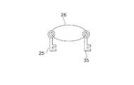
また、図5、6に示すように、各進入扉34には、進入防護柵31の外側及び内側から進入扉34を施錠するための施錠機構34aと、進入扉34の開閉状態(ここでは、施錠されているか否か)を電気的に検知するための扉スイッチ34bとが設けられている。図5は、進入扉34の構成を示す図であり、図6は、施錠キー35と監視キー25との連結構成を示す図である。 As shown in FIGS. 5 and 6, each
ここで、施錠機構34aを解錠又は施錠する施錠キー35は、全て同じキー形状を有しており、また、複数の進入扉34の施錠機構34aも、施錠キー35に適合するキー穴を有している。そして、施錠キー35は、監視キー25と同じ数(ここでは、16個)だけ準備されており、各施錠キー35は、ワイヤーや紐等の連結部材26によって、各監視キー25に連結されている。なお、施錠機構34aとしては、進入扉34のデッドボルト等からなるロック機構や南京錠等種々の形式のものが使用可能である。 Here, the locking
各扉スイッチ34bは、進入扉34又は施錠機構34aに一体化しており、施錠機構34aの開閉状態に関する検知信号をメインコントロールボックス21へ送信するようになっている。 Each
そして、進入者把握装置21bは、各扉スイッチ34bからメインコントロールボックス21が受信した検知信号に基づいて、開状態(すなわち、解錠された状態)の進入扉34が存在するか否かを判定する。進入者把握装置21bは、開状態の進入扉34が存在する場合には、メイン制御装置21aに対して、搬送車3への給電を遮断する給電遮断指令を行うようになっている。 Then, the intruder grasping device 21b determines whether or not there is an open door (that is, an unlocked state) based on the detection signal received by the
そして、メイン制御装置21aは、この給電遮断指令を受けて、自動運転実行の有無にかかわらず、起動ボタン23bや運転準備ボタン23dを押しても、その指令を受け付けずに給電を行わない状態にするようになっている。 Then, the main control device 21a receives this power supply cutoff command, and regardless of whether automatic operation is executed or not, even if the
なお、施錠機構34aの開閉状態を検知する手段としては、扉スイッチ34bに代えて、セーフティプラグを使用することも可能である。ただし、セーフティプラグを使用すると、進入扉34の実際の開閉状態とセーフティプラグの状態とが一致しないおそれがあることから、扉スイッチ34bを使用することが好ましい。 As a means for detecting the open / closed state of the
<進入防護柵内の通り抜け手順>
このような進入防護柵31内の通り抜け時の安全確保機能のための構成を備えた搬送車システム1では、以下の手順にしたがって、進入防護柵31内における進入者の安全を確保しつつ、進入防護柵31内の通り抜けを行うことができる。なお、以下の説明では、監視キー25は、各通り抜け監視ボックス24の複数(ここでは、8個)のキー装着部24a〜24hのうち4個のキー装着部24e〜24hに装着されており、自動運転が行われている状態を想定する。<Procedure for passing through the entry guard fence>
In the
まず、図7に示すように、進入防護柵31内の通り抜けをしようとする進入者は、搬送車3の自動運転を停止させるために、ローカルコントロールボックス23の自動停止ボタン23cを押す。これにより、搬送車3が自動運転の基準位置まで移動して停止するまで、自動運転ボタン23cの表示ランプが点灯する。搬送車3が停止した後は、自動停止ボタン23cの表示ランプが消灯し、起動ボタン23bの表示ランプが点灯状態から点滅状態に変わる。 First, as shown in FIG. 7, an intruder trying to pass through the
次に、図8に示すように、進入者は、進入扉34を開けるために、施錠キー35が連結された監視キー25(ここでは、キー装着部24eに装着されているもの)を左に回して抜く。これにより、通り抜け監視ボックス24のキー装着部24a〜24hに装着されている監視キー25の総数と予め記憶されている監視キー25の総数が異なる状態になる。より具体的には、キー装着部24a〜24hに装着されている監視キー25の総数が1個少ない状態になる。したがって、進入者把握装置21b(図2参照)が、進入防護柵31内への進入者がいるものと判定する。進入者把握装置21bは、さらに、メイン制御装置21a(図2参照)に対して、搬送車3の動作を制限するように運転制限指令を行う。これにより、起動ボタン23bを押しても、その指令を受け付けずに自動運転を開始しない状態になる。すなわち、進入防護柵31内における進入者の安全が確保され、進入扉34を通じて進入防護柵31内の通り抜けが可能な状態になる。 Next, as shown in FIG. 8, in order to open the
ここで、前の手順(図7参照)において、自動停止ボタン23cを押すことなく監視キー25をキー装着部24eから抜いた場合であっても、進入者把握装置21b(図2参照)が、メイン制御装置21a(図2参照)に対して運転制限指令を行う。したがって、上記と同じく、自動運転を開始しない状態になる。そして、進入者は、施錠キー35によって施錠機構34a(図5参照)を解錠し、進入扉34を開ける。これにより、扉スイッチ34b(図5参照)が進入扉34の開状態を検知するため、進入者把握装置21b(図2参照)が、メイン制御装置21a(図2参照)に対して、搬送車3への給電を遮断する給電遮断指令を行う。これにより、起動ボタン23bや運転準備ボタン23dを押しても、その指令を受け付けずに給電を行わない状態になる。なお、起動ボタン23b、自動停止ボタン23c及び運転準備ボタン23dの各表示ランプは、消灯状態に変わる。また、施錠キー35は、監視キー25に連結されているため、進入者は、監視キー25をキー装着部24a〜24h(ここでは、キー装着部24e)から抜くことなく、進入扉34を開けることができないようになっている。 Here, in the previous procedure (see FIG. 7), even if the monitoring
次に、図9に示すように、進入者は、進入防護柵31内に進入し、施錠キー35によって施錠機構34a(図5参照)を施錠し、進入扉34を閉める。ここで、施錠キー35は、監視キー25に連結されているため、進入者は、監視キー25を携帯した状態で進入防護柵31内に進入することになる。これにより、監視キー25を持たないで進入者が進入防護柵31内に進入することを確実に防ぐことができるようになっている。 Next, as shown in FIG. 9, the intruder enters the
次に、図10に示すように、進入者は、進入防護柵31内から通り抜け先の進入扉34を開けるために、施錠機構34a(図5参照)を解錠して、通り抜け先の進入扉34を開ける。そして、進入者は、進入防護柵31内を通り抜けた後に、施錠キー35によって施錠機構34a(図5参照)を施錠し、通り抜け先の進入扉34を閉める。そして、進入者は、施錠キー35が連結された監視キー25を、通り抜け先の通り抜け監視ボックス24のキー装着部24a〜24h(ここでは、キー装着部24a)に装着する。これにより、通り抜け監視ボックス24のキー装着部24a〜24hに装着されている監視キー25の総数と予め記憶されている監視キー25の総数が一致した状態になる。したがって、進入者把握装置21b(図2参照)が、進入防護柵31内への進入者がいないものと判定し、メイン制御装置21a(図2参照)に対して、運転制限指令を解除する指令を行う。この結果、運転準備ボタン23d及び起動ボタン23bが押されることによって搬送車3への給電指令及び搬送指令を受け付ける状態になる。 Next, as shown in FIG. 10, the intruder unlocks the
ここで、通り抜け監視ボックス24のキー装着部24a〜24hは、進入防護柵31の外側からのみ監視キー25の装着が可能になっており、進入防護柵31内から進入者が監視キー25をキー装着部24a〜24hに装着することができない。したがって、監視キー25がキー装着部24a〜24hに装着されている場合には、進入防護柵31内に進入者がいない状態を確保することができるようになっている。 Here, the
次に、図11に示すように、進入者は、通り抜け先のローカルコントロールボックス23の運転準備ボタン23dを押すことで、搬送車3への給電を開始し、続いて、起動ボタン23bを押すことで、自動運転を開始する。ただし、前の手順(図9、10参照)において、進入扉34の施錠が行われていない場合には、急に進入扉34が開いてしまう等の事態が生じるおそれがある。そこで、進入者把握装置21bは、各扉スイッチ34bからメインコントロールボックス21が受信した検知信号に基づいて、開状態(すなわち、解錠された状態)の進入扉34が存在することを検出すると、メイン制御装置21aに対して、搬送車3への給電を遮断する給電遮断指令を行うようになっている。 Next, as shown in FIG. 11, the intruder starts power supply to the
なお、図12に示すように、進入者が進入防護柵31内に進入している状態において、例えば、他の者が、搬送車3の運転を行うためにローカルコントロールボックス23の運転準備ボタン23dや起動ボタン23bを押したとする。この場合には、通り抜け監視ボックス24のキー装着部24a〜24hに装着されている監視キー25の総数と予め記憶されている監視キー25の総数が異なる状態になっているので、搬送車3への給電や自動運転が開始されないようになっている。しかも、この場合には、メインコントロールボックス21やローカルコントロールボックス23からブザー音等を発報することによって、把握した監視キー25の総数と予め記憶されている監視キー25の総数が異なることが報知される。これにより、搬送車システム1を起動できない理由を明確にできるため、進入者に対して進入防護柵31外へ退出することを促すことができるようになっている。 As shown in FIG. 12, in the state where the intruder has entered the
(4)特徴
自動運転機器システムとしての搬送車システム1は、自動運転機器としての走行路2及び搬送車3の周囲を進入防護柵31で囲い、進入防護柵31の一部に複数の進入扉34を設けたシステムである。搬送車システム1は、進入防護柵31の外側に設けられた複数のキー装着部24a〜24hと、進入者把握装置21bとを備えている。進入者把握装置21bは、キー装着部24a〜24hに装着されている監視キー25の総数を把握する。進入者把握装置21bは、この監視キー25の総数と予め記憶されている監視キー25の総数とを比較し、把握した監視キー25の総数と予め記憶されている監視キー25の総数が異なる場合には、搬送車3の動作を制限させる。
この搬送車システム1では、進入防護柵31内への進入者の有無の判定を行い、進入防護柵31内への進入者がいると判定された場合には、搬送車3の動作を制限することができる。この結果、進入防護柵31内における進入者の安全を確保しつつ、進入扉34を通じて進入防護柵31内の通り抜けを可能にすることができる。(4) Features The guided
In this
複数のキー装着部24a〜24hは、各進入扉34に対応して設けられている。 The plurality of key mounting
各進入扉34には、施錠機構34aが設けられており、施錠機構34aを解錠する施錠キー35は、監視キー25と連結されている。
この搬送車システム1では、進入防護柵31内への進入者が進入扉34を開ける際に、進入者が監視キー25を持った状態にすることができるため、監視キー25を持たないで進入者が進入防護柵31内に進入することを確実に防ぐことができる。Each
In this
キー装着部24a〜24hは、進入防護柵31の外側からのみ監視キー25の装着が可能になっている。
この搬送車システム1では、進入防護柵31内から進入者が監視キー25をキー装着部24a〜24hに装着することができないため、監視キー25がキー装着部24a〜24hに装着されている場合には、進入防護柵31内に進入者がいない状態を確保することができる。The
In this
把握した監視キー25の総数と予め記憶されている監視キー25の総数が異なる場合において搬送車3を起動するための指令が行われたときには、把握した監視キー25の総数と予め記憶されている監視キー25の総数が異なることを報知する。
この搬送車システム1では、搬送車3を起動できない理由を明確にできるため、進入者に対して進入防護柵31外へ退出することを促すことができる。When a command for starting the
In this
(5)他の実施形態
以上、本発明にかかる自動運転機器システムの一実施形態について説明したが、本発明は上記実施形態に限定されるものではなく、発明の要旨を逸脱しない範囲で種々の変更が可能である。(5) Other Embodiments Although one embodiment of the automatic driving equipment system according to the present invention has been described above, the present invention is not limited to the above-described embodiment, and various modifications can be made without departing from the gist of the invention. It can be changed.
自動運転機器システムとしては、搬送車システムに限定されず、旋盤等の自動運転工作機械であってもよい。
搬送車システムのレイアウト及び制御系は、上記実施形態に限定されない。The automatic driving device system is not limited to the carrier system, and may be an automatic driving machine tool such as a lathe.
The layout and control system of the transport vehicle system are not limited to the above embodiment.
監視キーは、上記実施形態に限定されず、磁気カードや電子タグ等の他の型式のキーであってもよく、この場合には、キー装着部も監視キーの型式に応じた構造を有するものであればよい。また、このような他の型式のキーを使用する場合においても、上記実施形態と同様、安全確保機能という観点において、いずれの監視キーもキー装着部によって同一の監視キーであると認識されるものにすることが好ましい。 The monitoring key is not limited to the above embodiment, and may be another type of key such as a magnetic card or an electronic tag. In this case, the key mounting portion also has a structure corresponding to the type of the monitoring key. If it is. In addition, even when such other types of keys are used, all the monitoring keys are recognized as the same monitoring key by the key mounting unit from the viewpoint of the safety ensuring function as in the above embodiment. It is preferable to make it.
上記実施形態では、施錠キーは監視キーと連結されているが、これに限定されず、監視キーと一体化したキーを使用したり、監視キーと共通化してもよい。 In the above embodiment, the locking key is connected to the monitoring key. However, the present invention is not limited to this, and a key integrated with the monitoring key may be used or may be shared with the monitoring key.
上記実施形態では、施錠機構として、南京錠等のような、施錠キーを使用して解錠や施錠を行うものが使用されているが、これに限定されず、自動運転が行われている場合のみ施錠が行われるように構成された電磁ロックのような施錠機構を使用してもよい。 In the above embodiment, a locking mechanism such as a padlock is used that unlocks and locks using a locking key, but is not limited to this, and only when automatic operation is performed. A locking mechanism such as an electromagnetic lock configured to be locked may be used.
上記実施形態では、通り抜け監視ボックス(すなわち、複数のキー装着部)は、進入防護柵の外側で、かつ、進入扉の近傍に自立設置されているが、これに限定されず、進入扉の外面等に設けられていてもよい。 In the above embodiment, the pass-through monitoring box (that is, a plurality of key mounting portions) is installed on the outside of the entry protection fence and in the vicinity of the entry door. However, the present invention is not limited to this. Etc. may be provided.
本発明は、自動運転機器の周囲を進入防護柵で囲い、進入防護柵の一部に複数の進入扉を設けた自動運転機器システムに広く適用可能である。 INDUSTRIAL APPLICABILITY The present invention can be widely applied to an automatic driving equipment system in which the periphery of an automatic driving equipment is surrounded by an entrance protection fence and a plurality of entrance doors are provided in part of the entrance protection fence.
1 搬送車システム(自動運転機器システム)
2 走行路(自動運転機器)
3 搬送車(自動運転機器)
31 進入防護柵
34 進入扉
24a〜24h キー装着部
25 監視キー
21b 進入者把握装置
34a 施錠機構
35 施錠キー1 Transport vehicle system (automated driving equipment system)
2 Traveling route (automatic driving equipment)
3 Car (automatic driving equipment)
31
Claims (4)
Translated fromJapanese前記進入防護柵の外側に、前記各進入扉に対応するように前記各進入扉のそれぞれに複数設けられたキー装着部と、
一の前記進入扉に対応するように設けられた前記キー装着部から、当該一の前記進入扉に対応するように設けられた他の前記キー装着部へ、又は、他の前記進入扉に対応するように設けられた他の前記キー装着部へ装着可能な監視キーと、
予め記憶されている監視キーの総数個準備された前記監視キーのうち、前記キー装着部に装着されている前記監視キーの総数を把握するとともに、前記監視キーの総数と予め記憶されている監視キーの総数とを比較し、前記把握した監視キーの総数と前記予め記憶されている監視キーの総数が異なる場合には、前記自動運転機器の動作を制限させる進入者把握装置と、
を備えた自動運転機器システム。Enclosure around the automatic operation device by entering fences, a automatic operation device system having a plurality of ingress doors in a part ofthe approach safety barrier,
A plurality of key attachment portions provided on each of the entry doors so as to correspond to the entry doors on the outside of the entry protection fence ,
From the key mounting part provided to correspond to one entry door to another key installation part provided to correspond to the one entry door, or to other entry door A monitoring key that can be mounted on the other key mounting portion provided to perform,
Among the monitored key has been total several preparations for monitoring key stored in advance, said to grasp the total number ofsaid monitoring key that is mounted on the key mounting part, the monitoring that is stored in advance and the total number of the monitoring key An intruder grasping device that restricts the operation of the automatic driving device, when the total number of the keys is compared with the total number of the monitored keys that are different from the total number of the monitoring keys that are stored in advance,
Automatic driving equipment system equipped with.
前記施錠機構を解錠する施錠キーは、前記監視キーと連結、一体化又は共通化されている、請求項1に記載の自動運転機器システム。Each of the entrance doors is provided with a locking mechanism,
Said locking key to unlock the locking mechanism, the connecting and monitoring key, are integrated or common, automatic operation device system according to claim1.
Priority Applications (1)
| Application Number | Priority Date | Filing Date | Title |
|---|---|---|---|
| JP2009132750AJP5141640B2 (en) | 2009-06-02 | 2009-06-02 | Automated driving equipment system |
Applications Claiming Priority (1)
| Application Number | Priority Date | Filing Date | Title |
|---|---|---|---|
| JP2009132750AJP5141640B2 (en) | 2009-06-02 | 2009-06-02 | Automated driving equipment system |
Publications (2)
| Publication Number | Publication Date |
|---|---|
| JP2010280450A JP2010280450A (en) | 2010-12-16 |
| JP5141640B2true JP5141640B2 (en) | 2013-02-13 |
Family
ID=43537596
Family Applications (1)
| Application Number | Title | Priority Date | Filing Date |
|---|---|---|---|
| JP2009132750AActiveJP5141640B2 (en) | 2009-06-02 | 2009-06-02 | Automated driving equipment system |
Country Status (1)
| Country | Link |
|---|---|
| JP (1) | JP5141640B2 (en) |
Cited By (3)
| Publication number | Priority date | Publication date | Assignee | Title |
|---|---|---|---|---|
| JP2015189560A (en)* | 2014-03-28 | 2015-11-02 | 村田機械株式会社 | Automatically driven equipment system |
| WO2024126232A1 (en)* | 2022-12-16 | 2024-06-20 | Autostore Technology AS | An automated storage and retrieval system comprising lockable barriers for safe transfer of persons into a transport vehicle on a live grid, and associated method |
| WO2024126230A1 (en)* | 2022-12-16 | 2024-06-20 | Autostore Technology AS | An automated storage and retrieval system with logically operable barriers for safe enter and exit into a transport vehicle, and an associated method |
Families Citing this family (1)
| Publication number | Priority date | Publication date | Assignee | Title |
|---|---|---|---|---|
| DE102023107535A1 (en)* | 2023-03-24 | 2024-09-26 | Gebhardt Fördertechnik GmbH | Shuttle system with a vertical conveyor module and method for rectifying a fault in a vertical conveyor module of a shuttle system |
Family Cites Families (4)
| Publication number | Priority date | Publication date | Assignee | Title |
|---|---|---|---|---|
| JPS6428101A (en)* | 1987-07-21 | 1989-01-30 | Daifuku Kk | Warehouse equipment |
| JP2667756B2 (en)* | 1992-03-06 | 1997-10-27 | 株式会社イトーキクレビオ | Maintenance safety control device in a three-dimensional warehouse |
| JP2923625B2 (en)* | 1995-10-16 | 1999-07-26 | 株式会社キトー | Stacker crane safety fence |
| JP3509393B2 (en)* | 1996-06-04 | 2004-03-22 | 株式会社ダイフク | Automatic warehouse |
- 2009
- 2009-06-02JPJP2009132750Apatent/JP5141640B2/enactiveActive
Cited By (3)
| Publication number | Priority date | Publication date | Assignee | Title |
|---|---|---|---|---|
| JP2015189560A (en)* | 2014-03-28 | 2015-11-02 | 村田機械株式会社 | Automatically driven equipment system |
| WO2024126232A1 (en)* | 2022-12-16 | 2024-06-20 | Autostore Technology AS | An automated storage and retrieval system comprising lockable barriers for safe transfer of persons into a transport vehicle on a live grid, and associated method |
| WO2024126230A1 (en)* | 2022-12-16 | 2024-06-20 | Autostore Technology AS | An automated storage and retrieval system with logically operable barriers for safe enter and exit into a transport vehicle, and an associated method |
Also Published As
| Publication number | Publication date |
|---|---|
| JP2010280450A (en) | 2010-12-16 |
Similar Documents
| Publication | Publication Date | Title |
|---|---|---|
| JP5141640B2 (en) | Automated driving equipment system | |
| EP3422502B1 (en) | Substation for medium or high voltage, containing switchgear or controlgear with unmanned operation and maintenance | |
| US8514054B2 (en) | Personnel key tracking system | |
| CN102092404B (en) | Device for preventing and detecting the falling of an object on a railway line, and method for detecting the falling of an object on the line | |
| EP3578435B1 (en) | Rail-mounted vehicle having passenger emergency escape roof hatch | |
| JP6260398B2 (en) | Automated driving equipment system | |
| KR101614861B1 (en) | Platform safety scaffolding and an electric train signal control system | |
| KR102567668B1 (en) | Worker safety management system and method for worker safety management | |
| US12195302B2 (en) | Safety monitoring device, and method for monitoring the safety of an elevator system | |
| JP2009050577A (en) | Delivery receipt system | |
| JP6117229B2 (en) | Device for controlling the operation of the machine, locking insert for such a device and the accompanying operating method | |
| KR200476125Y1 (en) | Safety System for Disconnecting Switch of Electric Car Line | |
| EP3502360B1 (en) | Construction machine equipped with battery | |
| KR102516393B1 (en) | Key safety guard, manufacturing method thereof and safety slide key door lock including the same | |
| US7446273B2 (en) | Safety lockout system for interrupting unintentional flow of electrical current controlled by a safety switch | |
| JP2923625B2 (en) | Stacker crane safety fence | |
| KR101607787B1 (en) | Entry/exit management system | |
| CN106447880A (en) | A comprehensive monitoring and jamming control system for the safety door of motor vehicle climbing to the top | |
| JP2011116272A (en) | Train protective method when installing set-off equipment, and train protective device for set-off equipment | |
| CN102748058B (en) | Device capable of automatically locking well after damage of ventilating pavilion protective window | |
| CN105118115B (en) | Enter leaving management system | |
| JPS6391710A (en) | Locking method for worker access door against automatically guided vehicle | |
| JP4929077B2 (en) | Key judgment system | |
| RU2745100C1 (en) | Parking hook (versions) | |
| JP2023048188A (en) | Safety management system |
Legal Events
| Date | Code | Title | Description |
|---|---|---|---|
| A977 | Report on retrieval | Free format text:JAPANESE INTERMEDIATE CODE: A971007 Effective date:20120719 | |
| A131 | Notification of reasons for refusal | Free format text:JAPANESE INTERMEDIATE CODE: A131 Effective date:20120731 | |
| A521 | Request for written amendment filed | Free format text:JAPANESE INTERMEDIATE CODE: A523 Effective date:20120928 | |
| TRDD | Decision of grant or rejection written | ||
| A01 | Written decision to grant a patent or to grant a registration (utility model) | Free format text:JAPANESE INTERMEDIATE CODE: A01 Effective date:20121023 | |
| A01 | Written decision to grant a patent or to grant a registration (utility model) | Free format text:JAPANESE INTERMEDIATE CODE: A01 | |
| A61 | First payment of annual fees (during grant procedure) | Free format text:JAPANESE INTERMEDIATE CODE: A61 Effective date:20121105 | |
| FPAY | Renewal fee payment (event date is renewal date of database) | Free format text:PAYMENT UNTIL: 20151130 Year of fee payment:3 | |
| R150 | Certificate of patent or registration of utility model | Ref document number:5141640 Country of ref document:JP Free format text:JAPANESE INTERMEDIATE CODE: R150 Free format text:JAPANESE INTERMEDIATE CODE: R150 | |
| R250 | Receipt of annual fees | Free format text:JAPANESE INTERMEDIATE CODE: R250 | |
| R250 | Receipt of annual fees | Free format text:JAPANESE INTERMEDIATE CODE: R250 | |
| R250 | Receipt of annual fees | Free format text:JAPANESE INTERMEDIATE CODE: R250 | |
| R250 | Receipt of annual fees | Free format text:JAPANESE INTERMEDIATE CODE: R250 | |
| R250 | Receipt of annual fees | Free format text:JAPANESE INTERMEDIATE CODE: R250 | |
| R250 | Receipt of annual fees | Free format text:JAPANESE INTERMEDIATE CODE: R250 | |
| R250 | Receipt of annual fees | Free format text:JAPANESE INTERMEDIATE CODE: R250 | |
| R250 | Receipt of annual fees | Free format text:JAPANESE INTERMEDIATE CODE: R250 | |
| R250 | Receipt of annual fees | Free format text:JAPANESE INTERMEDIATE CODE: R250 |