JP5140178B2 - Cooker - Google Patents
CookerDownload PDFInfo
- Publication number
- JP5140178B2 JP5140178B2JP2011152997AJP2011152997AJP5140178B2JP 5140178 B2JP5140178 B2JP 5140178B2JP 2011152997 AJP2011152997 AJP 2011152997AJP 2011152997 AJP2011152997 AJP 2011152997AJP 5140178 B2JP5140178 B2JP 5140178B2
- Authority
- JP
- Japan
- Prior art keywords
- heater
- fan
- blade
- protrusion
- radial direction
- Prior art date
- Legal status (The legal status is an assumption and is not a legal conclusion. Google has not performed a legal analysis and makes no representation as to the accuracy of the status listed.)
- Expired - Fee Related
Links
Images


Classifications
- F—MECHANICAL ENGINEERING; LIGHTING; HEATING; WEAPONS; BLASTING
- F24—HEATING; RANGES; VENTILATING
- F24C—DOMESTIC STOVES OR RANGES ; DETAILS OF DOMESTIC STOVES OR RANGES, OF GENERAL APPLICATION
- F24C15/00—Details
- F24C15/32—Arrangements of ducts for hot gases, e.g. in or around baking ovens
- F24C15/322—Arrangements of ducts for hot gases, e.g. in or around baking ovens with forced circulation
- F24C15/325—Arrangements of ducts for hot gases, e.g. in or around baking ovens with forced circulation electrically-heated
- F—MECHANICAL ENGINEERING; LIGHTING; HEATING; WEAPONS; BLASTING
- F24—HEATING; RANGES; VENTILATING
- F24C—DOMESTIC STOVES OR RANGES ; DETAILS OF DOMESTIC STOVES OR RANGES, OF GENERAL APPLICATION
- F24C7/00—Stoves or ranges heated by electric energy
- F24C7/06—Arrangement or mounting of electric heating elements
Landscapes
- Engineering & Computer Science (AREA)
- Chemical & Material Sciences (AREA)
- Combustion & Propulsion (AREA)
- Mechanical Engineering (AREA)
- General Engineering & Computer Science (AREA)
- Structures Of Non-Positive Displacement Pumps (AREA)
Description
Translated fromJapanese本発明は、加熱調理器に関する。 The present invention relates to a cooking device.
従来、加熱調理器としては、特開2009−24914号公報(特許文献1)に記載されているものがある。この加熱調理器は、本体ハウジングの後側にあるファンダクトの後側にファンを配置し、ファンで加熱室内の熱媒体を加熱室の吸込口から吸い込んで、径方向に吹き出して、上記熱媒体に熱交換させるようになっている。 Conventionally, as a heating cooker, there exists what is described in Unexamined-Japanese-Patent No. 2009-24914 (patent document 1). In this cooking device, a fan is disposed on the rear side of the fan duct on the rear side of the main body housing, and the heat medium in the heating chamber is sucked in from the suction port of the heating chamber by the fan and blown in the radial direction. Heat exchange.
上記ファンは、ファン本体と、ブレードとを有し、上記ブレードは、ファンの加熱室側の面からファンの軸方向の加熱室側に突出している。上記従来の加熱調理器では、上記加熱室側に突出するブレードによって、熱媒体の流動を規制して、熱媒体を、ファンの平面部に対する同一平面上かまたはそれよりも加熱室側に吹き出すようになっている。 The fan has a fan main body and a blade, and the blade protrudes from the surface of the fan on the heating chamber side toward the heating chamber in the axial direction of the fan. In the conventional cooking device, the flow of the heat medium is regulated by the blade protruding toward the heating chamber, and the heat medium is blown out on the same plane with respect to the flat portion of the fan or toward the heating chamber. It has become.
上記従来の加熱調理器では、加熱調理器の薄型化のために、上記ブレードの厚さを薄くすると、ファンの送風性能が下がって、熱媒体の熱交換を効率よく行うことができないという問題がある。また、これとは逆に、ファンの送風性能を上げるために、上記ブレードの厚さを厚くすると、ファンの軸方向の寸法が大きくなって、加熱調理器を薄型化できないという問題がある。 In the above-mentioned conventional cooking device, if the thickness of the blade is reduced in order to reduce the thickness of the cooking device, there is a problem that the fan blowing performance is lowered and heat exchange of the heat medium cannot be performed efficiently. is there. On the other hand, if the thickness of the blade is increased in order to improve the blowing performance of the fan, there is a problem that the axial dimension of the fan increases and the cooking device cannot be thinned.
そこで、本発明の課題は、ファンの送風性能が良好であると共に、ファンの軸方向の厚さが薄い加熱調理器を提供することにある。 Accordingly, an object of the present invention is to provide a cooking device that has a good fan blowing performance and a thin axial thickness of the fan.
上記課題を解決するため、この発明の加熱調理器は、
ケーシング内に位置する加熱室と、
この加熱室から熱媒体を吸い出すダクトと、
このダクトに設けられたファンと
を備え、
上記ダクトは、
板部と、
この板部から突出する突出部と
を有し、
上記ファンは、
上記突出部の先端部に回転自在に取り付けられると共に、周方向に互いに間隔をおいて位置する複数の羽根を有するファン本体と、
上記ファン本体の一方側に設けた第1ブレードと、
上記ファン本体の他方側に設けた第2ブレードと
を有し、
上記第1ブレードは、上記突出部の先端部よりも上記板部側とは反対側に位置する一方、上記第2ブレードは、上記突出部の先端部よりも上記板部側に位置して上記突出部の側方に位置し、
上記ファンを取り囲むように配置されたヒータ装置を備え、
上記第1ブレードが、上記各羽根の回転方向の後方側から上記ファン本体の軸方向の上記板部側とは反対側に突出している一方、上記第2ブレードが、上記各羽根の上記回転方向の前方側から軸方向の上記板部側に突出していることを特徴としている。In order to solve the above problems, the heating cooker of the present invention is:
A heating chamber located in the casing;
A duct for sucking out the heat medium from the heating chamber;
With a fan provided in this duct,
The duct is
A plate part;
Having a protruding portion protruding from the plate portion,
The above fans
A fan bodyhaving a plurality of vanes spaced from one another rotatably mountedRutotomoni, circumferentially distal end of the protrusion,
A first blade provided on one side of the fan body;
A second blade provided on the other side of the fan body,
The first blade is positioned on a side opposite to the plate portion side with respect to the tip portion of the protruding portion, while the second blade is positioned on the plate portion side with respect to the tip portion of the protruding portion. Located on the side of the protrusion,
A heater device arranged so as to surround the fan;
The first blade protrudes from the rear side in the rotation direction of each blade toward the opposite side to the plate portion side in the axial direction of the fan body, while the second blade is in the rotation direction of each blade. It is characterized in Rukotoof not protrude from the front side to the plate portion side in the axial direction.
尚、「上記第2ブレードは、上記突出部の先端部よりも上記板部側に位置して上記突出部の側方に位置し」という要件は、第2ブレードの一部が、突出部の先端部よりも板部側に位置して突出部の側方に位置していれば、満たされるものとする。 The requirement that “the second blade is located on the plate part side and on the side of the projecting part with respect to the tip part of the projecting part” is that the part of the second blade is the part of the projecting part. If it is located on the plate part side of the tip part and on the side of the projecting part, it is satisfied.
本発明によれば、突出部の先端部よりも板部側に位置して突出部の側方に位置する第2ブレードを有しているから、ファンの軸方向の熱媒体吸込側の表面を伝って径方向の外方側に流動する熱媒体を、第2ブレードを伝わせて、ファンの裏面側に効率よく送ることができる。 According to the present invention, since the second blade is located on the side of the projecting portion and on the side of the projecting portion from the tip portion of the projecting portion, the surface on the heat medium suction side in the axial direction of the fan is provided. The heat medium that flows to the outer side in the radial direction can be efficiently sent to the rear surface side of the fan along the second blade.
したがって、従来、熱媒体を殆ど流動させることができなくて、熱媒体の熱交換のデットスペースになっていたファンの裏面側のスペースを有効利用することができるから、ファンの送風性能を良好に保ったままで、ファンの表面側の第1ブレードの厚さを低減することができる。また、上記第2ブレードが、ファンモータを覆うために存在する突出部の側方に位置するから、第2ブレードを設けることに基づいてファンの軸方向の厚さが厚くなることはない。 Therefore, conventionally, the heat medium can hardly be flowed, and the space on the back side of the fan, which has been a dead space for heat exchange of the heat medium, can be effectively used. The thickness of the first blade on the surface side of the fan can be reduced while keeping it. Further, since the second blade is located on the side of the protruding portion that exists to cover the fan motor, the axial thickness of the fan does not increase based on the provision of the second blade.
したがって、ファンの送風性能を良好なままに維持できると共に、ファンの軸方向の厚さを低減できる。 Therefore, it is possible to maintain the fan's blowing performance as good and reduce the axial thickness of the fan.
また、一実施形態では、
上記突出部は、台状突出部であり、
上記先端部は、上記台状突出部の先端面である。In one embodiment,
The protrusion is a trapezoidal protrusion,
The tip portion is a tip surface of the trapezoidal protrusion.
上記実施形態によれば、上記突出部が、台状突出部であって、上記先端部が、上記台状突出部の先端面であるから、突出部にファン本体を安定的に固定することができる。 According to the embodiment, since the protrusion is a trapezoidal protrusion, and the tip is the tip surface of the trapezoid protrusion, the fan body can be stably fixed to the protrusion. it can.
また、上記実施形態によれば、上記突出部が、台状突出部であるから、ファンからの風が、突出部の側方に沿って流動し易くなって、ファンからの風をより効率的にヒータ装置に送ることができる。 Moreover, according to the said embodiment, since the said protrusion part is a base-like protrusion part, the wind from a fan becomes easy to flow along the side of a protrusion part, and the wind from a fan is more efficient. Can be sent to the heater device.
また、一実施形態では、
上記台状突出部は、円錐面からなる側面を有する円錐台状突出部であり、
上記第2ブレードは、上記円錐面からなる側面に沿うように延在している。In one embodiment,
The trapezoidal protrusion is a frustoconical protrusion having a side surface composed of a conical surface,
The second blade extends along a side surface composed of the conical surface.
上記実施形態によれば、上記台状突出部が、円錐面からなる側面を有するから、ファンからの風を、より円滑に台状突出部の側面に沿わせて流動させることができる。また、上記第2ブレードが、上記円錐面からなる側面に沿うように延在しているから、円錐面からなる側面に沿って流動している風を、乱流を起こさずに、効率的にヒータ装置の方に流動させることができる。 According to the embodiment, since the trapezoidal protrusion has a side surface formed of a conical surface, the wind from the fan can flow more smoothly along the side surface of the trapezoidal protrusion. In addition, since the second blade extends so as to extend along the side surface including the conical surface, the wind flowing along the side surface including the conical surface can be efficiently generated without causing turbulence. It can be made to flow toward the heater device.
また、上記実施形態によれば、台状突出部が、円錐面からなる側面を有する円錐台状突出部であって、上記第2ブレードが、上記側面に沿うように延在しているから、限られた展開寸法の中で、第2ブレードの表面積を増やすことができて、第2ブレードの送風性能を大きくすることができる。 Further, according to the embodiment, the trapezoidal protrusion is a truncated cone-shaped protrusion having a side surface formed of a conical surface, and the second blade extends along the side surface. The surface area of the second blade can be increased within a limited deployment size, and the blowing performance of the second blade can be increased.
また、一実施形態では、
上記ヒータ装置は、上記ファンの軸方向の位置が互いに異なる第1ヒータおよび第2ヒータを有し、
上記第1ヒータは、上記第1ブレードに上記ファンの径方向に重なっている一方、上記第2ヒータは、上記第2ブレードに上記径方向に重なっている。In one embodiment,
The heater device includes a first heater and a second heater in which the axial position of the fan is different from each other,
The first heater overlaps the first blade in the radial direction of the fan, while the second heater overlaps the second blade in the radial direction.
尚、「上記第1ヒータは、上記第1ブレードに上記ファンの径方向に重なっている」という要件は、第1ヒータの一部が、第1ブレードにファンの径方向に重なっていれば満たされるものとし、「上記第2ヒータは、上記第2ブレードに上記径方向に重なっている」という要件は、第2ヒータの一部が、第2ブレードにファンの径方向に重なっていれば満たされるものとする。 The requirement that “the first heater overlaps the first blade in the radial direction of the fan” is satisfied if a part of the first heater overlaps the first blade in the radial direction of the fan. The requirement that “the second heater overlaps the second blade in the radial direction” is satisfied if a part of the second heater overlaps the second blade in the radial direction of the fan. Shall be.
上記実施形態によれば、第1ヒータが、ファンの表側にある第1ブレードに径方向に重なっているから、第1ブレードによって、第1ヒータに効率よく熱媒体を送ることができて、第1ヒータの熱交換性能を優れたものにできる。 According to the above embodiment, since the first heater overlaps the first blade on the front side of the fan in the radial direction, the first blade can efficiently send the heat medium to the first heater, The heat exchange performance of one heater can be made excellent.
また、上記実施形態によれば、第2ヒータが、ファンの裏面にある第2ブレードに径方向に重なっているから、第2ブレードによって、第2ヒータに効率よく熱媒体を送ることができて、第2ヒータの熱交換性能を優れたものにできる。したがって、従来、熱媒体の熱交換のデットスペースになっていた、ファンの裏面側のスペースで、効率的に熱交換を行うことができる。 Further, according to the above embodiment, since the second heater overlaps the second blade on the back surface of the fan in the radial direction, the second blade can efficiently send the heat medium to the second heater. The heat exchange performance of the second heater can be made excellent. Therefore, heat exchange can be efficiently performed in the space on the back side of the fan, which has conventionally been a dead space for heat exchange of the heat medium.
また、一実施形態では、
ケーシング内に位置する加熱室と、
この加熱室から熱媒体を吸い出すダクトと、
このダクトに設けられたファンと
を備え、
上記ダクトは、
板部と、
この板部から突出する突出部と
を有し、
上記ファンは、
上記突出部の先端部に回転自在に取り付けられたファン本体と、
上記ファン本体の一方側に設けた第1ブレードと、
上記ファン本体の他方側に設けた第2ブレードと
を有し、
上記第1ブレードは、上記突出部の先端部よりも上記板部側とは反対側に位置する一方、上記第2ブレードは、上記突出部の先端部よりも上記板部側に位置して上記突出部の側方に位置し、
上記ファンを取り囲むように配置され、
上記ヒータ装置は、上記ファンの軸方向の位置が互いに異なる第1ヒータおよび第2ヒータを有し、
上記第1ヒータは、上記第1ブレードに上記ファンの径方向に重なっている一方、上記第2ヒータは、上記第2ブレードに上記径方向に重なっており、
上記第1ヒータおよび上記第2ヒータの夫々の上記ファンを取り囲んでいる部分は、上記軸方向に重なっており、
上記板部に固定されると共に、上記第1ヒータを固定する第1ヒータ固定部と、上記第2ヒータを固定する第2ヒータ固定部とを有するヒータ取付部材を備え、
上記ヒータ取付部材は、上記ファンの径方向に貫通する貫通穴および切欠きのうちの少なくとも一方を有している。In one embodiment,
A heating chamber located in the casing;
A duct for sucking out the heat medium from the heating chamber;
With the fan installed in this duct
With
The duct is
A plate part;
A protruding portion protruding from the plate portion,
Have
The above fans
A fan body rotatably attached to the tip of the protrusion,
A first blade provided on one side of the fan body;
A second blade provided on the other side of the fan body;
Have
The first blade is positioned on a side opposite to the plate portion side with respect to the tip portion of the protruding portion, while the second blade is positioned on the plate portion side with respect to the tip portion of the protruding portion. Located on the side of the protrusion,
Arranged to surround the fan,
The heater device includes a first heater and a second heater in which the axial position of the fan is different from each other,
The first heater overlaps the first blade in the radial direction of the fan, while the second heater overlaps the second blade in the radial direction,
The portions surrounding the respective fans of the first heater and the second heater overlap in the axial direction,
A heater attachment member fixed to the plate portion and having a first heater fixing portion for fixing the first heater and a second heater fixing portion for fixing the second heater;
The heater mounting member has at least one of a through hole and a notch penetrating in the radial direction of the fan.
本発明者は、ヒータ取付部材で、ヒータを固定した場合、そのヒータ取付部材で熱媒体の径方向の流れが遮られて、熱媒体の乱流が発生して、その乱流が、ファンによる熱媒体の良好な循環を妨げることを発見した。 When the heater is fixed by the heater mounting member, the inventor blocks the flow in the radial direction of the heat medium by the heater mounting member, and generates a turbulent flow of the heat medium. It has been found that hinders good circulation of the heat medium.
上記実施形態によれば、上記ヒータ取付部材は、径方向に貫通する貫通穴または切欠きを有しているから、この貫通穴または切欠きを介して熱媒体を径方向に流動させることができて、ファンの熱媒体の径方向の流れを円滑にすることができる。したがって、熱媒体を良好に循環させることができる。 According to the embodiment, since the heater mounting member has a through hole or a notch that penetrates in the radial direction, the heat medium can flow in the radial direction through the through hole or the notch. Thus, the radial flow of the heat medium of the fan can be made smooth. Therefore, the heat medium can be circulated well.
本発明によれば、ファンの送風性能が良好であるにも拘わらず、ファンの軸方向の厚さが薄い加熱調理器を実現できる。 ADVANTAGE OF THE INVENTION According to this invention, although the ventilation performance of a fan is favorable, the heating cooker with the thin thickness of the axial direction of a fan is realizable.
以下、本発明を図示の形態により詳細に説明する。 Hereinafter, the present invention will be described in detail with reference to the drawings.
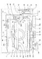
図1は、本発明の一実施形態の加熱調理器の斜視図である。 FIG. 1 is a perspective view of a heating cooker according to an embodiment of the present invention.
図1に示すように、この加熱調理器は、直方体形状のケーシング1の正面に、下端側の辺を略中心に回動する扉2が取り付けられている。この扉2の上部にハンドル3を取り付けると共に、扉2の略中央に耐熱ガラス4を取り付けている。また、扉2の右側に操作パネル5を設けている。この操作パネル5は、液晶表示部6とダイヤル7とを有している。また、ケーシング1の上側かつ右側後方に排気口8を設けている。さらに、ケーシング1の扉2の下方に、露受容器9を着脱自在に取り付けている。 As shown in FIG. 1, this cooking device is provided with a
図2は、この加熱調理器の正面から見た断面模式図である。 FIG. 2 is a schematic cross-sectional view seen from the front of the cooking device.
図2に示すように、この加熱調理器は、直方体形状のケーシング1内に、直方体形状の加熱室10が設けられている。加熱室10は、正面側に開口部を有し、加熱室10の側面,底面および天面にステンレス鋼製の遮熱板14が設けられている。加熱室10の周囲および扉2(図1に示す)の内側に断熱材(図示せず)が配置されており、加熱室10内と外部とが断熱されている。また、加熱室10内には、ステンレス製のトレイ21が設置され、トレイ21上には、被加熱物90を載置するためのステンレス鋼線製の調理網22が設置されている。上記加熱室10内の両側壁面にトレイ受部23,24を設け、このトレイ受部23,24によりトレイ21を受けている。 As shown in FIG. 2, the heating cooker includes a rectangular
また、この加熱調理器は、ケーシング1内かつ加熱室10の右側に、蒸気発生用の水を給水する水タンク30と、ポンプ31と、ポンプ31より水タンク30から供給された水を加熱して蒸気を発生させる蒸気発生装置40とを備えている。 In addition, the heating cooker heats water supplied from the
また、水タンク30の下側に設けられた接続部(図示せず)は、第1給水パイプ32の一端に設けられた受入口(図示せず)に接続可能になっている。第1給水パイプ32の他端をポンプ31の一端に接続している。このポンプ31の他端を第2給水パイプ33の一端に接続し、第2給水パイプ33の他端を蒸気発生装置40に接続している。 Further, a connection portion (not shown) provided on the lower side of the
上記加熱室10の後面の中央に、円形の吸込部20aを設けると共に、加熱室10の後面上側の左右コーナー近傍に、左上吹出部20bと右上吹出部20cを設けている。また、加熱室10の後面の吸込部20aの左右に、左中吹出部20dと右中吹出部20eを設け、加熱室10の後面下側の左右コーナー近傍に、下上吹出部20fと下上吹出部20gを設けている。また、加熱室10の右上側には、加熱室10内の雰囲気の温度を検出する庫内温度センサ76を配置している。 A
上記水タンク30の下側には、つゆ戻し桶34を配置している。また、ケーシング1内の加熱室10の下側に、電装品部50と、冷却ファン53と、その冷却ファン53を駆動する冷却ファン用モータ54とを配置している。この冷却ファン53は、底側の開口62から吸い込んだ空気によりケーシング1内の電装品部50等を冷却する。また、ケーシング1内の加熱室10の右側に、外部からの空気を吸気口57を介して加熱室10内に供給するための給気ファン55を配置している。 On the lower side of the
上記加熱室10の底面パネル10aよりも下側には、攪拌アンテナ51と、その攪拌アンテナ51を駆動する攪拌アンテナ用モータ52とが配置されている。マイクロ波発生装置の一例としてのマグネトロンで発生したマイクロ波は、導波管60によって加熱室10の下部中央に導かれ、攪拌アンテナ用モータ52によって駆動される攪拌アンテナ51によって攪拌されながら加熱室10内の上方に向かって放射されて、ターンテーブル300上に置かれた被加熱物90を加熱するようになっている。 A stirring
また、図2に示すように、加熱室10の右側面に設けられた排気口(図示せず)には、排気ダクト72の一端が接続され、この排気ダクト72の他端には排気口8が設けられている。この排気ダクト72内に排気温度センサ74を配置すると共に、排気ダクト72内の排気温度センサ74よりも加熱室10側に排気湿度センサ75を配置している。 As shown in FIG. 2, one end of an
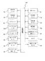
図3は、上記加熱調理器の制御ブロック図である。図3に示すように、制御装置100は、マイクロコンピュータおよび入出力回路等から構成され、図2に示す電装品部50内に配置されている。 FIG. 3 is a control block diagram of the cooking device. As shown in FIG. 3, the
上記制御装置100は、蒸気発生ヒータ42と、蒸気昇温ヒータ43と、マグネトロン61と、ヒータ装置としてのコンベクションヒータ422と、コンベクションファン用モータ83と、冷却ファン用モータ54と、攪拌アンテナ用モータ52と、操作パネル5と、排気温度センサ74と、排気湿度センサ75と、庫内温度センサ76と、蒸気発生ボックス温度センサ47と、ポンプ31と、給気ファン用モータ56と、駆動部の一例としてのターンテーブル用モータ84とが接続されている。そして、制御装置100は、排気温度センサ74,排気湿度センサ75,庫内温度センサ76および蒸気発生ボックス温度センサ47からの検出信号に基づいて、蒸気発生ヒータ42,蒸気昇温ヒータ43,マグネトロン61,コンベクションヒータ422,コンベクションファン用モータ83,冷却ファン用モータ54,攪拌アンテナ用モータ52,ポンプ31,給気ファン用モータ56およびターンテーブル用モータ84を所定のプログラムに従って制御する。 The
以下、上記構成の加熱調理器の蒸気加熱動作について、図1、図2および図3に従って説明する。 Hereinafter, the steam heating operation of the cooking device configured as described above will be described with reference to FIGS. 1, 2, and 3.
まず、操作パネル5の電源スイッチ(図示せず)が押圧されると電源がオンし、操作パネル5の操作によって、過熱水蒸気を用いたオーブン調理の運転が開始される。そうすると、制御装置100は、水タンク検知部(図示せず)により水タンク30が正常に装着されているか否かを検知して、水タンク30が正常に装着されていれば、ポンプ31の運転を開始する。そして、ポンプ31によって、水タンク30から蒸気発生装置40の蒸気発生ボックス41内に第2給水パイプ33を介して給水される。その後、蒸気発生ボックス41内に所定水量の水を給水すると、ポンプ31を停止して給水を止める。 First, when a power switch (not shown) of the
次に、蒸気発生ヒータ42に通電し、蒸気発生ボックス41内に溜まった所定量の水を蒸気発生ヒータ42によって加熱する。そして、蒸気発生ヒータ42の通電と同時に、または、蒸気発生ボックス温度センサ47により検出された蒸気発生ボックス41の温度が所定温度に達すると、コンベクションファン用モータ83によりコンベクションファンを駆動すると共に、コンベクションヒータ422に通電する。そうすると、コンベクションファンは、加熱室10内の熱媒体(蒸気を含む空気)を吸込部20aから吸い込んで、コンベクションヒータ422により加熱された熱媒体を、吸込部20a,20b,20c,20d,20e,20f,20gを介して加熱室10内に送り出す。 Next, the
次に、蒸気発生装置40の蒸気発生ボックス41内の水が沸騰すると飽和蒸気が発生し、発生した飽和蒸気は、蒸気昇温部45内の蒸気昇温ヒータ43により加熱されて100℃以上(調理内容により異なる)の過熱水蒸気となって蒸気パイプ46を介して蒸気吹出口44から加熱室10内に供給される。 Next, when the water in the steam generation box 41 of the
この過熱水蒸気は、加熱室10内の空気と共に、コンベクションファンにより吸込部20aから吸い込まれて、コンベクションヒータ422により加熱されて、吸込部20a,20b,20c,20d,20e,20f,20gから加熱室10内に吹き出し、加熱室10内の被加熱物90を包むような対流が形成される。こうして、対流する熱媒体(主に過熱水蒸気)は、順次吸込部20aに吸い込まれて、コンベクションファンダクトを通って再び加熱室10内に戻るという循環を繰り返す。 The superheated steam is sucked from the
このようにして、上記加熱室10内で過熱蒸気の対流を形成することによって、加熱室10内の温度・湿度分布を均一に維持しつつ、調理網22上に載置された被加熱物90に効率よく過熱蒸気を衝突させることが可能になり、過熱蒸気の衝突によって被加熱物90が加熱される。その場合、被加熱物90の表面に接触した過熱蒸気は、被加熱物90の表面で結露する際に潜熱を放出することによっても被加熱物90を加熱する。これにより、過熱蒸気の大量の熱を確実に且つ速やかに被加熱物90全面に均等に与えることができる。したがって、斑がなくて仕上がりのよい加熱調理を実現することができる。 In this way, by forming a convection of superheated steam in the
また、上記加熱調理運転時において、時間が経過すると、加熱室10内の蒸気量が増加し、量的に余剰となった分の蒸気は、排気口71から排気ダクト72を介して排気口8から外部に放出される。 In addition, when time elapses during the cooking operation, the amount of steam in the
調理終了後、制御装置100によって操作パネル5に調理終了のメッセージが表示され、さらに操作パネル5に設けられたブザー(図示せず)によって合図の音を鳴らす。 After cooking is finished, the
以上の説明は、過熱水蒸気を用いたオーブン料理の場合である。なお、水蒸気を用いた蒸し料理の場合は、コンベクションファンを駆動せず、コンベクションヒータ422を通電しないで、上記と同様の動作を行う。 The above explanation is the case of oven cooking using superheated steam. In the case of steamed dishes using steam, the convection fan is not driven and the
また、マイクロ波加熱動作の場合には、使用者によって操作パネル5が操作され、マイクロ波調理メニューが決定された後にスタートキー(図示せず)が押圧されると、マイクロ波加熱調理の運転が開始される。そうすると、制御装置100は、マグネトロン61を駆動して、導波管60および攪拌アンテナ51を介して被加熱物90にマイクロ波を供給し、被加熱物90を加熱する。このとき、被加熱物90が載置されたターンテーブル300を載せたテーブルトレイ200(図2参照)が、加熱室10内の底面パネル10a上に着脱自在に取り付けられる。このターンテーブル300およびテーブルトレイ200はマイクロ波を透過する。 In the case of the microwave heating operation, when the
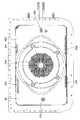
図4は、加熱室10の背面400を示す図であり、吹出部20aおよび吹出部20b,20c,20d,20e,20f,20gの詳細な形状を示す図である。 FIG. 4 is a view showing the
図4に示すように、吸込部20aは、背面の中央部に存在しており、複数の貫通穴からなっている。また、吹出部20b,20c,20d,20e,20f,20gの夫々も、複数の貫通穴で構成されている。 As shown in FIG. 4, the
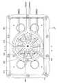
図5は、背面400の加熱調理器の前後方向(奥行き方向)の加熱室10側とは反対側に存在するコンベクションファンダクト401内のコンベクションファン410を、上記前後方向の背面400側から見たときの図である。尚、コンベクションファンダクト401は、加熱室10から熱媒体を吸い出すダクトを構成している。 FIG. 5 shows the
図5に示すように、コンベクションファン410は、コンベクションファンダクト401の背面415の中央に回転自在に据え付けられている。コンベクションファン410は、複数の羽根450を有し、その複数の羽根450は、ファンの周方向に略等間隔に配置されている。上記コンベクションファン410は、加熱室10の吸込部20aから熱媒体を吸い込んで、その吸い込んだ熱媒体を、径方向に吹き出すようになっている。 As shown in FIG. 5, the
また、この加熱調理器は、上記コンベクションヒータ422と、二つのヒータ取付部材425とを有し、コンベクションヒータ422は、コンベクションファン410の略全周を取り囲むように配置されている。上記コンベクションヒータ422は、ヒータ取付部材425によって背面415に固定されている。 The cooking device includes the
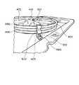
図6は、コンベクションファン410のコンベクションファンダクト401への取付構造を示す図であり、取付過程で、コンベクションファンダクト401の定位置に載置されたコンベクションファン410を示す斜視図である。 FIG. 6 is a view showing a structure for attaching the
図6に示すように、コンベクションファンダクト401の背面415は、板部420と、台状突出部の一例としての円錐台状突出部430とを有し、円錐台状突出部430は、板部420から加熱調理器の奥行き方向に突出している。上記円錐台状突出部430は、円錐面からなる側面435と、先端部の一例としての平面からなる先端面436を有している。上記コンベクションファン410の中心は、先端面436に回転自在に取り付けられるようになっている。コンベクションファン410を、先端面436に取り付けた状態で、コンベクションファン410の軸中心は、側面435の中心軸と略一致するようになっている。 As shown in FIG. 6, the
図6に示すように、上記コンベクションファン410は、ファン本体482と、第1ブレードとしての吸込側折り返し470と、第2ブレードとしての背面折り返し460とを有している。上記背面折り返し460は、図6に矢印Aで示す羽根450の回転方向の前方側からコンベクションファン410の軸方向の板部420側に突出している。上記背面折り返し460は、羽根450の径方向の途中の位置から羽根450の径方向の外端まで存在している。上記背面折り返し460は、円錐台状突出部430の先端面436よりも板部420側に位置して円錐台状突出部430の側方に位置している。上記背面折り返し460は、コンベクションファン410の軸方向の板部420側の面530から円錐台状突出部430の側面435に沿うように延在している。 As shown in FIG. 6, the
上記吸込側折り返し470は、回転方向の前方側からコンベクションファン410の軸方向の吸込側に突出している。上記吸込側折り返し470は、円錐台状突出部430の先端面436よりも板部420側とは反対側に位置している。上記吸込側折り返し470は、羽根450の径方向の略全範囲にわたって存在している。上記背面折り返し460および吸込側折り返し470の夫々は、略コンベクションファン410の軸方向に突出している。 The suction side turn-
尚、詳述しないが、上記ファン本体482は、羽根450毎にリブを有し、各リブは、羽根450の略中心を、羽根450の延在方向に延在している。上記リブは、羽根450の強度を大きくするために設けられている。 Although not described in detail, the fan
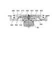
図7は、コンベクションファンダクト401に取り付けられたコンベクションファン410と、コンベクションヒータ422とを示す斜視図である。 FIG. 7 is a perspective view showing the
図7に示すように、上記コンベクションヒータ422は、第1ヒータとしての表側ヒータ480および第2ヒータとしての裏側ヒータ490を有している。表側ヒータ480と第2ヒータ480は、同じ円形の断面形状を有している。上記表側ヒータ480および裏側ヒータ490の夫々は、コンベクションファン410を取り囲むように配置されている。上記表側ヒータ480は、裏側ヒータ490よりもコンベクションファン410の軸方向の熱媒体吸込側(軸方向の板部420側とは反対側)に位置している。 As shown in FIG. 7, the
上記表側ヒータ480および裏側ヒータ490の夫々は、コンベクションファン410の軸方向に垂直な平面上に位置しており、コンベクションファンダクト401の背面415の板部420と略平行な状態になっている。 Each of the front-
上記表側ヒータ480および裏側ヒータ490の夫々のコンベクションファン410を取り囲んでいる部分は、円弧形状を有している。上記表側ヒータ480の円弧形状の部分の中心および径は、裏側ヒータ490の円弧形状の部分の中心および径と略同一になっている。上記表側ヒータ480の円弧形状の部分は、裏側ヒータ490の円弧形状の部分に、コンベクションファン410の軸方向に重なっている。上記各ヒータ取付部材425は、表側ヒータ480の円弧形状の部分と、裏側ヒータ490の円弧形状の部分とを同時に固定している。 The part surrounding each
図8は、上記ヒータ取付部材425の斜視図である。 FIG. 8 is a perspective view of the
図8に示すように、上記ヒータ取付部材425は、第1の断面半円状部501と、第1の矩形状平面部502と、第2の断面半円状部503と、第2の矩形状平面部504と、第3の矩形状平面部505とを有している。上記第1の矩形状平面部502の一端部は、第1の断面半円状部501の一端部に接続され、第2の断面半円状部503の一端部は、第1の矩形状平面部502の他端部に接続されている。また、上記第2の矩形状平面部504の一端部は、第2の断面半円状部503の他端部に接続されている。また、上記第3の矩形状平面部505の一端部は、第2の矩形状平面部504の他端部に接続されている。上記第1の矩形状平面部502と、第2の矩形状平面部504とは、同一平面上に位置している。上記第3の矩形状平面部505は、第2の矩形状平面部504の延在方向に垂直な方向に延在している。上記第2の矩形状平面部504は、その厚さ方向に延在する貫通穴510を有する一方、第3の矩形状平面部505は、その厚さ方向に延在するボルト挿通穴515を有している。 As shown in FIG. 8, the
再度、図7を参照して、各ヒータ取付部材425の第3の矩形状平面部505は、コンベクションファンダクト401の背面415の板部420に当接するように配置されている。ボルト挿通穴515の第1の矩形状平面部502側からボルト560をボルト挿通穴515に挿通して、ボルト560を板部420にねじ込むことにより、ヒータ取付部材425を板部420に固定するようになっている。 Referring to FIG. 7 again, the third rectangular
図5を参照して、表側ヒータ480の円弧形状の部分と、裏側ヒータ490の円弧形状の部分とは、同じ周方向の位相の位置の2箇所で、ヒータ取付部材425によって、拘束されている。詳しくは、図7を参照して、各ヒータ取付部材425の第1の断面半円状部501の半円筒状の凹部に表側ヒータ480を嵌め込むと共に、ヒータ取付部材425の第2の断面半円状部503の半円筒状の凹部に裏側ヒータ490を嵌め込んだ状態で、各ヒータ取付部材425を板部420に固定することにより、表側ヒータ480および裏側ヒータ490を所定の位置に固定するようになっている。図7に示すように、ヒータ取付部材425を板部420に固定した状態で、ヒータ取付部材425の貫通穴510は、コンベクションファン410の略径方向に延在している。また、ヒータ取付部材425を板部420に固定した状態で、ヒータ取付部材425の貫通穴510は、裏側ヒータ490よりもコンベクションファン410の軸方向の熱媒体吸込側とは反対側(軸方向の板部420側)に位置している。 Referring to FIG. 5, the arc-shaped portion of
図9は、図5のAA線断面図である。 9 is a cross-sectional view taken along line AA in FIG.
図9に示すように、円錐台状突出部430の裏側には凹部590が存在し、その凹部590には、コンベクションファン410のコンベクションファン用モータ83の一部が収容されている。このようにして、加熱調理器において、コンベクションファン410の軸方向の寸法を低減するようになっている。図9において、601は、コンベクションファン用モータ83の回転軸を示している。図9に示すように、回転軸601は、円錐台状突出部430の先端面436を貫通して、コンベクションファン410の中心に固定されている。 As shown in FIG. 9, a
図9に示すように、裏側ヒータ490は、コンベクションファン410の軸方向の熱媒体吸込側とは反対側の面530よりも上記軸方向の熱媒体吸込側とは反対側に位置している。また、背面折り返し460の一部は、円錐台状突出部430の側面435にコンベクションファン410の径方向に重なっている。 As shown in FIG. 9, the
また、図9に示すように、上記表側ヒータ480の略全ての部分は、吸込側折り返し470にコンベクションファン410の径方向に重なっている一方、裏側ヒータ490の一部は、背面折り返し460の一部にコンベクションファン410の径方向に重なっている。 Further, as shown in FIG. 9, almost all of the
このようにして、吸込側折り返し470で径方向に案内された熱媒体を、効率的に表側ヒータ480に到達させて、表側ヒータ480の熱交換性能を向上させるようになっていると共に、背面折り返し460で径方向に案内された熱媒体を、効率的に裏側ヒータ490に到達させて、裏側ヒータ490の熱交換性能を向上させるようになっている。 In this way, the heat medium guided in the radial direction by the suction side folding 470 is allowed to efficiently reach the
上記実施形態の加熱調理器によれば、円錐台状突出部430の先端面436よりも板部420側に位置して円錐台状突出部430の側方に位置する背面折り返し460を有しているから、コンベクションファン410の軸方向の熱媒体吸込側の表面を伝って径方向の外方側に流動する熱媒体を、背面折り返し460を伝わせて、コンベクションファン410の裏面側に効率よく送ることができる。 According to the cooking device of the above embodiment, it has the
したがって、従来、熱媒体を殆ど流動させることができなくて、熱媒体の熱交換のデットスペースになっていたコンベクションファン410の裏面側のスペースを有効利用することができるから、コンベクションファン410の送風性能を良好に保ったままで、コンベクションファン410の表面側の吸込側折り返し470の厚さを低減することができる。また、上記背面折り返し460が、コンベクションファン用モータ83を覆うために従来から存在する台状突出部430の側方に位置するから、背面折り返し460を設けることに基づいてコンベクションファン410の軸方向の厚さが厚くなることはない。 Therefore, the space on the back side of the
したがって、コンベクションファン410の送風性能を良好なままに維持できると共に、コンベクションファン410の軸方向の厚さを低減できる。 Therefore, while the ventilation performance of the
また、上記実施形態の加熱調理器によれば、突出部が、円錐台状突出部430であって、台状突出部であり、かつ、先端部が、その台状突出部としての円錐台状突出部430の先端面であるから、突出部に、ファン本体482を安定的に固定することができる。 Moreover, according to the heating cooker of the said embodiment, a protrusion part is a truncated cone-shaped
また、上記実施形態の加熱調理器によれば、上記突出部が、円錐台状突出部430であって、台状突出部であるから、コンベクションファン410からの風が、突出部の側方に沿って流動し易くなって、コンベクションファン410からの風をより効率的にコンベクションヒータ422に送ることができる。 Moreover, according to the heating cooker of the said embodiment, since the said protrusion part is the truncated cone-shaped
また、上記実施形態の加熱調理器によれば、上記台状突出部が、円錐台状突出部430であって、円錐面からなる側面435を有するから、コンベクションファン410からの風を、より円滑に側面435に沿わせて流動させることができる。また、第2ブレードである背面折り返し460が、上記円錐面からなる側面435に沿うように延在しているから、円錐面からなる側面435に沿って流動している風を、乱流を起こさずに、効率的にコンベクションヒータ422の方に流動させることができる。 Moreover, according to the heating cooker of the said embodiment, since the said trapezoid protrusion is the truncated cone-shaped
また、上記実施形態の加熱調理器によれば、台状突出部が、円錐面からなる側面435を有する円錐台状突出部430であって、第2ブレードである背面折り返し460が、上記側面435に沿うように延在しているから、限られた展開寸法の中で、背面折り返し460の表面積を増やすことができて、背面折り返し460の送風性能を大きくすることができる。 Moreover, according to the heating cooker of the said embodiment, a trapezoid protrusion part is the truncated cone-shaped
また、上記実施形態の加熱調理器によれば、表側ヒータ480が、コンベクションファン410の表側にある吸込側折り返し470に径方向に重なっているから、吸込側折り返し470によって、表側ヒータ480に効率よく熱媒体を送ることができて、表側ヒータ480の熱交換性能を優れたものにできる。 Moreover, according to the heating cooker of the said embodiment, since the
また、上記実施形態の加熱調理器によれば、裏側ヒータ490が、コンベクションファン410の裏面にある背面折り返し460に径方向に重なっているから、背面折り返し460によって、裏側ヒータ490に効率よく熱媒体を送ることができて、裏側ヒータ490の熱交換性能を優れたものにできる。したがって、従来、熱媒体の熱交換のデットスペースになっていた、コンベクションファン410の裏面側のスペースで、効率的に熱交換を行うことができる。 Moreover, according to the heating cooker of the said embodiment, since the
また、上記実施形態の加熱調理器によれば、上記ヒータ取付部材425は、略コンベクションファン410の径方向に貫通する貫通穴510を有しているから、この貫通穴510を介して熱媒体を径方向に流動させることができて、コンベクションファン410の熱媒体の径方向の流れを円滑にすることができる。したがって、熱媒体を良好に循環させることができる。仮に、ヒータ取付部材に径方向に延在する貫通穴または切欠きがなければ、ヒータ取付部材で熱媒体の径方向の流れが遮られて、ヒータ取付部材付近で熱媒体の乱流が発生して、その乱流が、ファンによる熱媒体の良好な循環を妨げることになるのである。 Moreover, according to the heating cooker of the said embodiment, since the said
また、上記実施形態の加熱調理器によれば、ヒータ取付部材425の貫通穴510が、裏側ヒータ490よりも板部420側に存在しているから、熱媒体の流れが滞りがちになり易いコンベクションファン410の裏面側での熱媒体の流れを円滑にすることができる。したがって、コンベクションファン410の送風性能の向上の効果が大きくなる。 Moreover, according to the heating cooker of the said embodiment, since the through-
尚、上記実施形態の加熱調理器では、第2ブレードとしての背面折り返し460が、図6に矢印Aで示す羽根450の回転方向の前方側からコンベクションファン410の軸方向の吸込側とは反対側(コンベクションファン410の軸方向のコンベクションファンダクト401の板部420側)に突出していたが、この発明では、第2ブレードは、コンベクションファンの軸方向の吸込側とは反対側の面の如何なる位置からファンの軸方向のダクトの板部側に突出していても良い。尚、この実施形態のように、第2ブレードが、羽根の回転方向の前方側からファンの軸方向のダクトの板部側に突出するようになっていれば、熱媒体を円滑に第2ブレードに沿わすことができて、第2ブレードでより多くの量の熱媒体を径方向に流動させることができる。 In the heating cooker of the above embodiment, the
また、上記実施形態の加熱調理器では、コンベクションヒータ422が、ヒータ480,490を二つ有していたが、この発明では、ヒータ装置は、ヒータを一つしか有していなくても良く、また、ヒータを三つ以上有していても良い。尚、ヒータを一つしか有していない場合は、例えば、断面積が大きい一重に巻かれたヒータを用いることにより、ファンの裏面側での効率的な熱交換を実現できる。また、例えば、ヒータを一つしか有していない場合に、その一つしかないヒータは、螺旋状に二重に巻かれた構成であっても良い。尚、この場合、例えば、上記実施形態で説明したヒータ取付部材425を使用して、その一つのヒータを固定することができることは言うまでもない。また、例えば、ヒータを一つしか有していない場合に、その一つしかないヒータは、螺旋状に三重以上の巻数で巻かれた構造であっても良い。 Moreover, in the heating cooker of the said embodiment, although the
また、上記実施形態の加熱調理器は、ヒータ480,490を二つ有し、かつ、その二つのヒータ480,490のコンベクションファン410を取り囲んでいる部分が、軸方向に重なっていたが、この発明は、ヒータを複数有し、そのうちの少なくとも二つのヒータのファンを取り囲む部分のファンの径方向の位置が互いに異なっていても良い。 In addition, the heating cooker of the above embodiment has two
また、上記実施形態の加熱調理器では、ヒータ取付部材425の貫通穴510が、コンベクションファン410の裏面側の裏側ヒータ490よりも更にコンベクションファン410の裏面側に位置していたが、この発明では、ヒータ取付部材の貫通穴は、ファンの略径方向に延在していれば、ヒータ取付部材の如何なる位置に存在していても良い。 Moreover, in the heating cooker of the said embodiment, although the through-
また、上記実施形態の加熱調理器では、ヒータ取付部材425が、コンベクションファン410の径方向に延在している貫通穴510を有していたが、この発明では、ヒータ取付部材は、ファンの径方向に延在している貫通穴およびファンの径方向に延在している切欠きを有していても良く、または、ファンの径方向に延在している切欠きのみを有していても良い。また、この発明では、ヒータ取付部材は、ファンの径方向に延在している二以上の貫通穴を有していても良く、ファンの径方向に延在している二以上の切欠きを有していても良い。 Moreover, in the heating cooker of the said embodiment, although the
また、上記実施形態の加熱調理器では、背面折り返し460の一部が、裏側ヒータ490にコンベクションファン410の略径方向に重なっていたが、この発明では、第2ブレードの全部が、第2ヒータにコンベクションファンの略径方向に重なっていても良く、または、第2ブレードの全部が、第2ヒータにコンベクションファンの略径方向に重なっていなくても良い。また、この発明では、第1ブレードの一部が、第1ヒータにファンの略径方向に重なっていても良く、第1ブレードの全部が、第1ヒータにファンの略径方向に重なっていても良く、第1ブレードの全部が、第1ヒータにファンの略径方向に重なっていなくても良い。 Moreover, in the heating cooker of the said embodiment, although a part of back folding | returning 460 overlapped the
また、上記実施形態の加熱調理器では、台状突出部が、円錐台状突出部430で、その側面435が、円錐面であったが、この発明では、台状突出部が、円筒台状突出部で、その側面が、円筒面であっても良い。 Moreover, in the heating cooker of the said embodiment, the trapezoid protrusion part was the truncated cone-shaped
また、上記実施形態の加熱調理器では、突出部が、円錐台状突出部430であって、台状突出部であったが、この発明では、突出部は、台状突出部でなくても良い。例えば、この発明の突出部は、台状突出部でなく、ファン本体が回転自在に取り付けられるのが、突出部の先端部を構成する球面等であっても良い。 Moreover, in the heating cooker of the said embodiment, although the protrusion part was a truncated cone-shaped
また、上記実施形態の加熱調理器では、第2ブレードとしての背面折り返し460が、コンベクションファン410の軸方向の板部420側の面530から円錐台状突出部430の側面435に沿うように延在していた。しかしながら、この発明では、第2ブレードは、突出部の先端部よりも板部側に位置して突出部の側方に位置していさえすれば良く、第2ブレードは、突出部の側方に沿って延在していなくても良い。 In the cooking device of the above embodiment, the
また、上記実施形態の加熱調理器では、コンベクションファン410が、加熱調理器の前後方向に略垂直な平面上に位置する構成であったが、この発明では、ファンは、加熱調理器の高さ方向に略垂直な平面上に位置する構成であっても良く、または、ファンは、加熱調理器の幅方向に略垂直な平面上に位置する構成で合っても良い。 Moreover, in the heating cooker of the said embodiment, although the
また、この発明の加熱調理器は、蒸気調理器、電子レンジ、オーブン等、ファンを用いて、熱媒体を循環させる構成であれば、如何なる調理器であっても良く、上記実施形態のように蒸気を利用する構成であっても良く、または、蒸気を利用しない構成であっても良い。 Further, the cooking device of the present invention may be any cooking device as long as it is configured to circulate the heat medium using a fan, such as a steam cooking device, a microwave oven, and an oven, as in the above embodiment. A configuration using steam or a configuration not using steam may be used.
1 ケーシング
10 加熱室
401 コンベクションファンダクト
410 コンベクションファン
420 板部
422 コンベクションヒータ
425 ヒータ取付部材
430 円錐台状突出部
436 円錐台状突出部の先端面
460 背面折り返し
470 吸込側折り返し
480 表側ヒータ
482 ファン本体
490 裏側ヒータ
510 ヒータ取付部材の貫通穴DESCRIPTION OF
Claims (5)
Translated fromJapaneseこの加熱室から熱媒体を吸い出すダクトと、
このダクトに設けられたファンと
を備え、
上記ダクトは、
板部と、
この板部から突出する突出部と
を有し、
上記ファンは、
上記突出部の先端部に回転自在に取り付けられると共に、周方向に互いに間隔をおいて位置する複数の羽根を有するファン本体と、
上記ファン本体の一方側に設けた第1ブレードと、
上記ファン本体の他方側に設けた第2ブレードと
を有し、
上記第1ブレードは、上記突出部の先端部よりも上記板部側とは反対側に位置する一方、上記第2ブレードは、上記突出部の先端部よりも上記板部側に位置して上記突出部の側方に位置し、
上記ファンを取り囲むように配置されたヒータ装置を備え、
上記第1ブレードが、上記各羽根の回転方向の後方側から上記ファン本体の軸方向の上記板部側とは反対側に突出している一方、上記第2ブレードが、上記各羽根の上記回転方向の前方側から軸方向の上記板部側に突出していることを特徴とする加熱調理器。A heating chamber located in the casing;
A duct for sucking out the heat medium from the heating chamber;
With a fan provided in this duct,
The duct is
A plate part;
Having a protruding portion protruding from the plate portion,
The above fans
A fan bodyhaving a plurality of vanes spaced from one another rotatably mountedRutotomoni, circumferentially distal end of the protrusion,
A first blade provided on one side of the fan body;
A second blade provided on the other side of the fan body,
The first blade is positioned on a side opposite to the plate portion side with respect to the tip portion of the protruding portion, while the second blade is positioned on the plate portion side with respect to the tip portion of the protruding portion. Located on the side of the protrusion,
A heater device arranged so as to surround the fan;
The first blade protrudes from the rear side in the rotation direction of each blade toward the opposite side to the plate portion side in the axial direction of the fan body, while the second blade is in the rotation direction of each blade. the cooking device, characterized in Rukotofrom the front side protrude to the plate portion side in the axial direction.
上記突出部は、台状突出部であり、
上記先端部は、上記台状突出部の先端面であることを特徴とする加熱調理器。The heating cooker according to claim 1, wherein
The protrusion is a trapezoidal protrusion,
The cooking device according to claim 1, wherein the tip portion is a tip surface of the trapezoidal protrusion.
上記台状突出部は、円錐面からなる側面を有する円錐台状突出部であり、
上記第2ブレードは、上記円錐面からなる側面に沿うように延在していることを特徴とする加熱調理器。The cooking device according to claim 2,
The trapezoidal protrusion is a frustoconical protrusion having a side surface composed of a conical surface,
The heating cooker, wherein the second blade extends along a side surface formed of the conical surface.
上記ヒータ装置は、上記ファンの軸方向の位置が互いに異なる第1ヒータおよび第2ヒータを有し、
上記第1ヒータは、上記第1ブレードに上記ファンの径方向に重なっている一方、上記第2ヒータは、上記第2ブレードに上記径方向に重なっていることを特徴とする加熱調理器。In the heating cooker according to any one of claims 1 to 3,
The heater device includes a first heater and a second heater in which the axial position of the fan is different from each other,
The cooking device according to claim 1, wherein the first heater overlaps the first blade in the radial direction of the fan, and the second heater overlaps the second blade in the radial direction.
この加熱室から熱媒体を吸い出すダクトと、
このダクトに設けられたファンと
を備え、
上記ダクトは、
板部と、
この板部から突出する突出部と
を有し、
上記ファンは、
上記突出部の先端部に回転自在に取り付けられたファン本体と、
上記ファン本体の一方側に設けた第1ブレードと、
上記ファン本体の他方側に設けた第2ブレードと
を有し、
上記第1ブレードは、上記突出部の先端部よりも上記板部側とは反対側に位置する一方、上記第2ブレードは、上記突出部の先端部よりも上記板部側に位置して上記突出部の側方に位置し、
上記ファンを取り囲むように配置され、
上記ヒータ装置は、上記ファンの軸方向の位置が互いに異なる第1ヒータおよび第2ヒータを有し、
上記第1ヒータは、上記第1ブレードに上記ファンの径方向に重なっている一方、上記第2ヒータは、上記第2ブレードに上記径方向に重なっており、
上記第1ヒータおよび上記第2ヒータの夫々の上記ファンを取り囲んでいる部分は、上記軸方向に重なっており、
上記板部に固定されると共に、上記第1ヒータを固定する第1ヒータ固定部と、上記第2ヒータを固定する第2ヒータ固定部とを有するヒータ取付部材を備え、
上記ヒータ取付部材は、上記ファンの径方向に貫通する貫通穴および切欠きのうちの少なくとも一方を有していることを特徴とする加熱調理器。A heating chamber located in the casing;
A duct for sucking out the heat medium from the heating chamber;
With the fan installed in this duct
With
The duct is
A plate part;
A protruding portion protruding from the plate portion,
Have
The above fans
A fan body rotatably attached to the tip of the protrusion,
A first blade provided on one side of the fan body;
A second blade provided on the other side of the fan body;
Have
The first blade is positioned on a side opposite to the plate portion side with respect to the tip portion of the protruding portion, while the second blade is positioned on the plate portion side with respect to the tip portion of the protruding portion. Located on the side of the protrusion,
Arranged to surround the fan,
The heater device includes a first heater and a second heater in which the axial position of the fan is different from each other,
The first heater overlaps the first blade in the radial direction of the fan, while the second heater overlaps the second blade in the radial direction,
The portions surrounding the respective fans of the first heater and the second heater overlap in the axial direction,
A heater attachment member fixed to the plate portion and having a first heater fixing portion for fixing the first heater and a second heater fixing portion for fixing the second heater;
The cooking device according to claim 1, wherein the heater mounting member has at least one of a through hole and a notch penetrating in a radial direction of the fan.
Priority Applications (3)
| Application Number | Priority Date | Filing Date | Title |
|---|---|---|---|
| JP2011152997AJP5140178B2 (en) | 2011-07-11 | 2011-07-11 | Cooker |
| CN201280034400.3ACN103649643B (en) | 2011-07-11 | 2012-07-10 | Heating device |
| PCT/JP2012/067579WO2013008813A1 (en) | 2011-07-11 | 2012-07-10 | Heating cooker |
Applications Claiming Priority (1)
| Application Number | Priority Date | Filing Date | Title |
|---|---|---|---|
| JP2011152997AJP5140178B2 (en) | 2011-07-11 | 2011-07-11 | Cooker |
Publications (2)
| Publication Number | Publication Date |
|---|---|
| JP2013019589A JP2013019589A (en) | 2013-01-31 |
| JP5140178B2true JP5140178B2 (en) | 2013-02-06 |
Family
ID=47506096
Family Applications (1)
| Application Number | Title | Priority Date | Filing Date |
|---|---|---|---|
| JP2011152997AExpired - Fee RelatedJP5140178B2 (en) | 2011-07-11 | 2011-07-11 | Cooker |
Country Status (3)
| Country | Link |
|---|---|
| JP (1) | JP5140178B2 (en) |
| CN (1) | CN103649643B (en) |
| WO (1) | WO2013008813A1 (en) |
Cited By (1)
| Publication number | Priority date | Publication date | Assignee | Title |
|---|---|---|---|---|
| CN104739230A (en)* | 2015-02-05 | 2015-07-01 | 宁波方太厨具有限公司 | Inner container heating type steam box |
Families Citing this family (19)
| Publication number | Priority date | Publication date | Assignee | Title |
|---|---|---|---|---|
| KR101513456B1 (en)* | 2013-04-30 | 2015-04-20 | 동부대우전자 주식회사 | Cooking apparatus |
| KR101520611B1 (en)* | 2013-04-30 | 2015-05-21 | 동부대우전자 주식회사 | Cooking apparatus |
| CN103885173B (en)* | 2014-03-13 | 2016-07-13 | 明基材料有限公司 | Light switching module |
| GB2552546A (en) | 2016-07-29 | 2018-01-31 | Johnson Matthey Plc | Oxidation catalyst for a compression ignition engine and a method of preparation therefor |
| WO2019032876A1 (en) | 2017-08-09 | 2019-02-14 | Sharkninja Operating Llc | Cooking device and components thereof |
| USD914447S1 (en) | 2018-06-19 | 2021-03-30 | Sharkninja Operating Llc | Air diffuser |
| USD883015S1 (en) | 2018-08-09 | 2020-05-05 | Sharkninja Operating Llc | Food preparation device and parts thereof |
| USD934027S1 (en) | 2018-08-09 | 2021-10-26 | Sharkninja Operating Llc | Reversible cooking rack |
| USD883014S1 (en) | 2018-08-09 | 2020-05-05 | Sharkninja Operating Llc | Food preparation device |
| USD903413S1 (en) | 2018-08-09 | 2020-12-01 | Sharkninja Operating Llc | Cooking basket |
| US11051654B2 (en) | 2019-02-25 | 2021-07-06 | Sharkninja Operating Llc | Cooking device and components thereof |
| WO2020176477A1 (en) | 2019-02-25 | 2020-09-03 | Sharkninja Operating Llc | Cooking system with guard |
| CN212346260U (en) | 2019-02-26 | 2021-01-15 | 沙克忍者运营有限责任公司 | Cooking system capable of being positioned on a support surface and mountable cooking system |
| USD982375S1 (en) | 2019-06-06 | 2023-04-04 | Sharkninja Operating Llc | Food preparation device |
| USD918654S1 (en) | 2019-06-06 | 2021-05-11 | Sharkninja Operating Llc | Grill plate |
| US11678765B2 (en) | 2020-03-30 | 2023-06-20 | Sharkninja Operating Llc | Cooking device and components thereof |
| CN113491454A (en) | 2020-04-06 | 2021-10-12 | 沙克忍者运营有限责任公司 | Cooking system positionable on a support surface |
| DE102020132482A1 (en)* | 2020-12-07 | 2022-06-09 | Welbilt Deutschland GmbH | Cooking device, in particular commercial cooking device |
| KR20240154969A (en)* | 2023-04-19 | 2024-10-28 | 엘지전자 주식회사 | Cooking appliance |
Family Cites Families (8)
| Publication number | Priority date | Publication date | Assignee | Title |
|---|---|---|---|---|
| JPS6372410U (en)* | 1986-10-29 | 1988-05-14 | ||
| JPH02213615A (en)* | 1989-02-10 | 1990-08-24 | Sanyo Electric Co Ltd | Cooker |
| JPH10267280A (en)* | 1997-03-27 | 1998-10-09 | Sanyo Electric Co Ltd | Heat circulating type heating cooker |
| CN1312435C (en)* | 2002-04-29 | 2007-04-25 | 乐金电子(天津)电器有限公司 | Ventilating and heating structure for microwave oven |
| JP2003336852A (en)* | 2002-05-20 | 2003-11-28 | Sanyo Electric Co Ltd | Heating cooker |
| JP2005114226A (en)* | 2003-10-07 | 2005-04-28 | Matsushita Electric Ind Co Ltd | Cooker |
| CN1779343A (en)* | 2004-11-26 | 2006-05-31 | 乐金电子(天津)电器有限公司 | Convection portion structure of convection electronic microwave oven |
| JP2009024914A (en)* | 2007-07-18 | 2009-02-05 | Sanyo Electric Co Ltd | Food cooking device |
- 2011
- 2011-07-11JPJP2011152997Apatent/JP5140178B2/ennot_activeExpired - Fee Related
- 2012
- 2012-07-10WOPCT/JP2012/067579patent/WO2013008813A1/enactiveApplication Filing
- 2012-07-10CNCN201280034400.3Apatent/CN103649643B/ennot_activeExpired - Fee Related
Cited By (1)
| Publication number | Priority date | Publication date | Assignee | Title |
|---|---|---|---|---|
| CN104739230A (en)* | 2015-02-05 | 2015-07-01 | 宁波方太厨具有限公司 | Inner container heating type steam box |
Also Published As
| Publication number | Publication date |
|---|---|
| CN103649643A (en) | 2014-03-19 |
| JP2013019589A (en) | 2013-01-31 |
| CN103649643B (en) | 2016-03-30 |
| WO2013008813A1 (en) | 2013-01-17 |
Similar Documents
| Publication | Publication Date | Title |
|---|---|---|
| JP5140178B2 (en) | Cooker | |
| JP6263745B2 (en) | Cooker | |
| US20110132346A1 (en) | Cooking device | |
| JP2009293820A (en) | Cabinet built-in type heating cooker | |
| CN107850312B (en) | heating cooker | |
| JP2002206748A (en) | Heating apparatus for microwave oven | |
| JP6782400B2 (en) | Cooker | |
| JP2009008297A (en) | Cooker | |
| JP6402367B2 (en) | Microwave heating device | |
| CN104456648B (en) | Micro-wave oven | |
| CN101377317B (en) | Heating cooking device | |
| JP5767901B2 (en) | Cooker | |
| JP2009008298A (en) | Cooker | |
| JP5084897B2 (en) | Cooker | |
| CN104329702A (en) | Hot blast microwave oven | |
| JP2010054097A (en) | Heating cooker | |
| JP2009264693A (en) | Heating device | |
| CN104665570B (en) | Flat board steam oven | |
| JP2007003042A (en) | Cooker | |
| JP2009008296A (en) | Cooker | |
| JP2015203518A (en) | heating cooker | |
| JP5923406B2 (en) | Cooker | |
| JP2011080710A (en) | Heating device | |
| JP2010243116A (en) | Cooker | |
| JP4576296B2 (en) | Cooker |
Legal Events
| Date | Code | Title | Description |
|---|---|---|---|
| TRDD | Decision of grant or rejection written | ||
| A01 | Written decision to grant a patent or to grant a registration (utility model) | Free format text:JAPANESE INTERMEDIATE CODE: A01 | |
| A61 | First payment of annual fees (during grant procedure) | Free format text:JAPANESE INTERMEDIATE CODE: A61 Effective date:20121116 | |
| R150 | Certificate of patent or registration of utility model | Ref document number:5140178 Country of ref document:JP Free format text:JAPANESE INTERMEDIATE CODE: R150 Free format text:JAPANESE INTERMEDIATE CODE: R150 | |
| FPAY | Renewal fee payment (event date is renewal date of database) | Free format text:PAYMENT UNTIL: 20151122 Year of fee payment:3 | |
| LAPS | Cancellation because of no payment of annual fees |