JP5138705B2 - Alternating light source to reduce specular reflection - Google Patents
Alternating light source to reduce specular reflectionDownload PDFInfo
- Publication number
- JP5138705B2 JP5138705B2JP2009547248AJP2009547248AJP5138705B2JP 5138705 B2JP5138705 B2JP 5138705B2JP 2009547248 AJP2009547248 AJP 2009547248AJP 2009547248 AJP2009547248 AJP 2009547248AJP 5138705 B2JP5138705 B2JP 5138705B2
- Authority
- JP
- Japan
- Prior art keywords
- illuminator
- image
- illuminators
- phase
- camera
- Prior art date
- Legal status (The legal status is an assumption and is not a legal conclusion. Google has not performed a legal analysis and makes no representation as to the accuracy of the status listed.)
- Expired - Fee Related
Links
Images


Classifications
- G—PHYSICS
- G03—PHOTOGRAPHY; CINEMATOGRAPHY; ANALOGOUS TECHNIQUES USING WAVES OTHER THAN OPTICAL WAVES; ELECTROGRAPHY; HOLOGRAPHY
- G03B—APPARATUS OR ARRANGEMENTS FOR TAKING PHOTOGRAPHS OR FOR PROJECTING OR VIEWING THEM; APPARATUS OR ARRANGEMENTS EMPLOYING ANALOGOUS TECHNIQUES USING WAVES OTHER THAN OPTICAL WAVES; ACCESSORIES THEREFOR
- G03B15/00—Special procedures for taking photographs; Apparatus therefor
- G03B15/02—Illuminating scene
- G—PHYSICS
- G02—OPTICS
- G02B—OPTICAL ELEMENTS, SYSTEMS OR APPARATUS
- G02B27/00—Optical systems or apparatus not provided for by any of the groups G02B1/00 - G02B26/00, G02B30/00
- G02B27/28—Optical systems or apparatus not provided for by any of the groups G02B1/00 - G02B26/00, G02B30/00 for polarising
- G—PHYSICS
- G03—PHOTOGRAPHY; CINEMATOGRAPHY; ANALOGOUS TECHNIQUES USING WAVES OTHER THAN OPTICAL WAVES; ELECTROGRAPHY; HOLOGRAPHY
- G03B—APPARATUS OR ARRANGEMENTS FOR TAKING PHOTOGRAPHS OR FOR PROJECTING OR VIEWING THEM; APPARATUS OR ARRANGEMENTS EMPLOYING ANALOGOUS TECHNIQUES USING WAVES OTHER THAN OPTICAL WAVES; ACCESSORIES THEREFOR
- G03B21/00—Projectors or projection-type viewers; Accessories therefor
- G—PHYSICS
- G03—PHOTOGRAPHY; CINEMATOGRAPHY; ANALOGOUS TECHNIQUES USING WAVES OTHER THAN OPTICAL WAVES; ELECTROGRAPHY; HOLOGRAPHY
- G03B—APPARATUS OR ARRANGEMENTS FOR TAKING PHOTOGRAPHS OR FOR PROJECTING OR VIEWING THEM; APPARATUS OR ARRANGEMENTS EMPLOYING ANALOGOUS TECHNIQUES USING WAVES OTHER THAN OPTICAL WAVES; ACCESSORIES THEREFOR
- G03B33/00—Colour photography, other than mere exposure or projection of a colour film
- G03B33/10—Simultaneous recording or projection
- G03B33/12—Simultaneous recording or projection using beam-splitting or beam-combining systems, e.g. dichroic mirrors
- G—PHYSICS
- G06—COMPUTING OR CALCULATING; COUNTING
- G06F—ELECTRIC DIGITAL DATA PROCESSING
- G06F3/00—Input arrangements for transferring data to be processed into a form capable of being handled by the computer; Output arrangements for transferring data from processing unit to output unit, e.g. interface arrangements
- G06F3/01—Input arrangements or combined input and output arrangements for interaction between user and computer
- G06F3/03—Arrangements for converting the position or the displacement of a member into a coded form
- G06F3/041—Digitisers, e.g. for touch screens or touch pads, characterised by the transducing means
- G06F3/042—Digitisers, e.g. for touch screens or touch pads, characterised by the transducing means by opto-electronic means
- G06F3/0425—Digitisers, e.g. for touch screens or touch pads, characterised by the transducing means by opto-electronic means using a single imaging device like a video camera for tracking the absolute position of a single or a plurality of objects with respect to an imaged reference surface, e.g. video camera imaging a display or a projection screen, a table or a wall surface, on which a computer generated image is displayed or projected
- G—PHYSICS
- G02—OPTICS
- G02B—OPTICAL ELEMENTS, SYSTEMS OR APPARATUS
- G02B27/00—Optical systems or apparatus not provided for by any of the groups G02B1/00 - G02B26/00, G02B30/00
- G02B27/0018—Optical systems or apparatus not provided for by any of the groups G02B1/00 - G02B26/00, G02B30/00 with means for preventing ghost images
Landscapes
- Engineering & Computer Science (AREA)
- Physics & Mathematics (AREA)
- General Physics & Mathematics (AREA)
- General Engineering & Computer Science (AREA)
- Theoretical Computer Science (AREA)
- Multimedia (AREA)
- Human Computer Interaction (AREA)
- Optics & Photonics (AREA)
- Studio Devices (AREA)
- Image Input (AREA)
- User Interface Of Digital Computer (AREA)
- Controls And Circuits For Display Device (AREA)
Description
Translated fromJapanese多くの計算システムおよびその他のデバイスの機能性は、ディスプレイを用いた、情報の有効な表示を拠り所としている。最近になって、ディスプレイは直接入力デバイスとして対話的に用いられるようにもなっている。例えば、ディスプレイに接触検知抵抗性および/または容量性アレイを装備すると、接触されているディスプレイの部分を検出することができる。 The functionality of many computing systems and other devices relies on the effective display of information using displays. Recently, displays have also been used interactively as direct input devices. For example, if the display is equipped with a touch sensitive resistive and / or capacitive array, the portion of the display that is being touched can be detected.
従来の対話型ディスプレイには、「ビジョン・キャプチャー」技術を用いるものがあり、カメラをディスプレイの背後に配置し、ディスプレイは透過性材料または半透過性材料の1又は2以上の層で構成されている。赤外線照明器もディスプレイの背後に配置されており、ディスプレイの手前にある物体またはディスプレイと接触する物体を照明する。照明光(即ち、照明器から発する光)は、物体から反射されて、カメラ内で受光され、反射光の写真を撮影する。この写真はシステムへの電子入力として取り込まれる。ディスプレイの手前に物体が置かれると、カメラが撮影するその画像に影響を及ぼすので、物体は情報をシステムに入力するために用いることができる。 Some conventional interactive displays use “vision capture” technology, with the camera placed behind the display, the display being composed of one or more layers of transmissive or translucent material. Yes. An infrared illuminator is also located behind the display and illuminates an object in front of or in contact with the display. Illumination light (that is, light emitted from the illuminator) is reflected from the object, received in the camera, and a photograph of the reflected light is taken. This photo is captured as an electronic input to the system. If an object is placed in front of the display, it affects the image that the camera takes, so the object can be used to input information into the system.
照明光の一部は、物体から反射するのではなく、ディスプレイを形成する透過性層または半透過性層の比較的平坦な表面から反射する。その結果、カメラは比較的強い強度の鏡面反射を、ディスプレイの特定区域において受光することになる。鏡面反射が非常に強いと、鏡面反射の区域内では入力物体から実際に反射するいずれの画像も区別するのが困難になる場合もあり得る。鏡面反射は、その特定の区域においてカメラを飽和させることもあり得る。その効果は、よく晴れた日に人が浅い池を見おろす状況に、いくらか類似する。人は、太陽のまばゆい反射またはその近くの区域を除いて、池の底を見ることができるであろう。 Some of the illumination light is not reflected from the object, but from the relatively flat surface of the transmissive or semi-transmissive layer that forms the display. As a result, the camera receives a relatively strong intensity specular reflection in a specific area of the display. If the specular reflection is very strong, it may be difficult to distinguish any image that actually reflects from the input object within the specular area. Specular reflection can saturate the camera in that particular area. The effect is somewhat similar to the situation where a person looks down a shallow pond on a sunny day. A person will be able to see the bottom of the pond, with the exception of the dazzling reflection of the sun or the nearby area.
したがって、鏡面反射は、対話型ディスプレイを入力として用いることができる条件(ability)に悪影響を及ぼす可能性がある。特に、カメラが鏡面反射を受ける区域に入力物体が位置付けられる場合にあてはまる。 Thus, specular reflection can adversely affect the ability to use an interactive display as an input. This is especially true when the input object is located in an area where the camera receives specular reflection.
必須ではないが、本発明の実施形態は、鏡面反射を低減または消去するために、交互に照明器を用いる対話型ディスプレイに関する。対話型ディスプレイは、多数の照明器と少なくとも1つのカメラとを含み、これらは1又は2以上の表示層の背後に置かれている。対話型ディスプレイは、当該対話型ディスプレイの照明フェーズを制御するフェーズ制御メカニズムを用いる。第1フェーズの間、第1照明器が第2照明器よりも優勢になるように制御する。例えば、第1照明器をオンにして、第2照明器をオフにすればよい。その状態において、カメラに画像を撮影させる。第2フェーズの間、第2照明器が第1照明器よりも優勢になるように制御する。 Although not required, embodiments of the present invention relate to interactive displays that use alternating illuminators to reduce or eliminate specular reflections. An interactive display includes a number of illuminators and at least one camera, which are placed behind one or more display layers. Interactive displays use a phase control mechanism that controls the lighting phase of the interactive display. During the first phase, the first illuminator is controlled to be more dominant than the second illuminator. For example, the first illuminator may be turned on and the second illuminator may be turned off. In that state, the camera is caused to take an image. During the second phase, the second illuminator is controlled to be more dominant than the first illuminator.
次いで、第1および第2画像の組み合わせを用いて、合併画像を明確に表現する。合併画像は、第2画像の一部を用いて、第1画像からの鏡面反射が目立たなくなるまたは消去さえするように、またはその逆に、形成することができる。鏡面反射が重なり合わないように光源を位置付けると、鏡面反射の影響を緩和することまたは排除することもできる。 The combined image is then clearly expressed using a combination of the first and second images. The merged image can be formed using a portion of the second image so that the specular reflection from the first image is less noticeable or even erased, or vice versa. Positioning the light source so that the specular reflections do not overlap can also mitigate or eliminate the effects of specular reflections.
この摘要は、詳細な説明において以下で更に説明する概念から選択したものを、簡略化した形態で導入するために設けられている。この摘要は、特許請求する主題の鍵となる特徴や必須の特徴を特定することを意図するのではなく、特許請求する主題の範囲を限定する際に補助として用いられることを意図するのでもない。 This summary is provided to introduce a selection of concepts in a simplified form that are further described below in the detailed description. This summary is not intended to identify key or essential features of the claimed subject matter, nor is it intended to be used as an aid in limiting the scope of the claimed subject matter. .
添付図面は、本発明の実施形態を更に特定的に説明するために用いられる。これらの図面は、本発明の典型的な実施形態のみを描画し、したがってその範囲を限定すると見なしてはならないことを理解の上で、添付図面を使用して、実施形態について一層具体的かつ詳細に記載し説明する。
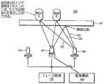
本発明の実施形態は、照明フェーズを交代することによって鏡面反射を低減する対話型ディスプレイに及ぶ。図8は、1又は2以上の表示層810の背後に1つの照明器802のみを有する対話型ディスプレイ800を用いる場合の問題点をいくつか示す。対話型ディスプレイ800は、1又は2以上の透過性または半透過性層810上に物体を配置し、これらの層810から表示光を放出することによって入力を受けるように構成されている。表示メカニズムは、図8には余り詳しく示されていないが、これとは別個に、対話型ディスプレイ800は撮像メカニズムを含む。具体的には、照明器802が光を放出する。この光は、表示動作を妨害しないように、表示される光と同じスペクトルではないのが通例である。 Embodiments of the present invention extend to interactive displays that reduce specular reflection by alternating illumination phases. FIG. 8 illustrates some of the problems when using an
照明器802は、多くの方向に光を放出する。光の一部はディスプレイから放出されるが、表示動作を妨害しない。何故なら、これは表示される画像とは周波数スペクトルが異なるからである。他の光は、表示層810の前面(即ち、図8における上面上または上面の上方)に置かれている物体から反射する。つまり、反射光はディスプレイの手前にある物体に関する情報を表す。他の光は、表示層180の平坦面から反射し、つまりディスプレイの手前にある物体に関する情報を表すのではなく、単なる鏡面反射である。 The
例えば、鏡面反射の妨害を例示するために、3本の光線821、822、および823を、照明器802から放出されたものとして示す。光線821および822は、ディスプレイ810の手前にある物体から反射し、したがって有効な入力情報を表す。一方、光線823は表示層810の平坦面から反射し、したがって鏡面反射を表す。このため、鏡面反射は、ほぼ物体Aの領域においてカメラ801によって観察することができる。したがって、物体Aはカメラ801による観察が不可能となる、または観察が困難となる場合があり得る。一方、物体Bは鏡面反射の区域に近接しておらず、したがって鏡面反射に対する心配なく観察することができる。このように、対話型ディスプレイ800は、鏡面反射に対応するディスプレイのある領域に入力物体が置かれた場合、適正に動作しない可能性がある。 For example, three
図1は、本発明の一実施形態による対話型ディスプレイ100を示す。図示するよりも多くの照明器およびカメラがあってもよいが、対話型ディスプレイ100は、2つの照明器102および103ならびに1つのカメラ101を含むように示されており、これらは各々透過性または半透過性表示層110(以後、簡単に「表示層110」と呼ぶ)の背後に配置されている。カメラ101および照明器102の表示層110に対する位置付けは、カメラ801および照明器802の表示層810に対する位置付けと同様である(図1および図8を比較されたい)。したがって、図1には示されていないが、対話型ディスプレイには、照明器102がオンのとき、カメラ101の物体Aの検出を妨害する鏡面反射がある。 FIG. 1 illustrates an
同様に、第2照明器103がオンであり第1照明器102がオフである場合も、鏡面反射が生ずるが、画像の異なる領域においてカメラ101によって感知される。要するに、照明器102および103は、表示層110背後の異なる位置に配置されている。照明器103は多くの光線を放出しているが、3本の光線121、122、および123のみが示されている。光線121は、物体Aから反射して、カメラ101に受光される。光線122は、物体Bから反射して、カメラ101に受光される。光線123は表示層110から反射することによって、鏡面反射を表し、カメラ101に受光される。照明器103がオン、照明器102がオフになると、物体AおよびBは双方ともカメラ101によって感知することができる。何故なら、これらは双方共、照明器103によって生ずる鏡面反射の区域から遠ざかるからである。しかしながら、鏡面反射の区域に近接する物体があると、その物体は、照明器103がオンである間は、カメラ101が感知するのは一層遥かに困難となる可能性がある。 Similarly, when the
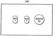
図3Aは、第1照明器102がオンであり、第2照明器103がオフであるときに、カメラ101によって取り込むことができる画像300Aの表現を示す。既に論じたように、画像300Aは、鏡面反射321の区域を有し、例えば、物体Aのように、鏡面反射321の区域がある物体を知覚する能力が損なわれる。一方、物体Bのように、鏡面反射321の区域の外側にある物体は、画像300A内部において一層容易に観察することができる。図3Bは、第1照明器102がオフであり、第2照明器103がオンであるときに、カメラ101によって取り込むことができる画像300Bを示す。画像300Bも鏡面反射322の区域を有し、鏡面反射322内部の物体を感知する能力が損なわれる。一方、物体AおよびBのように、鏡面反射322の区域の外側にある物体は、一層容易に観察することができる。 FIG. 3A shows a representation of an
図1を参照すると、対話型ディスプレイ100は、フェーズ管理メカニズム130も含む。フェーズ管理メカニズム130は、対話型ディスプレイ100の照明フェーズを管理する。図2は、フェーズ管理メカニズム130の動作例を示す状態図200を例示する。状態201において、メカニズム130は対話型ディスプレイの次のフェーズ変化を待つ(状態201)。実際には、タイミングがしかるべきときに、次のフェーズ変化を制御する。第1フェーズ(状態遷移矢印211)に遷移すると、第1照明器102が第2照明器103よりも優勢になるように制御される(状態221)。 Referring to FIG. 1, the
ここで、以下の説明においていくつかの定義を明記し、その後に図2の状態図200の主要な説明に戻ることにする。この説明および特許請求の範囲では、一つの照明器が別の照明器よりも「優勢になる」なるように制御すると言う場合、優勢な照明器に劣性な照明器よりも多くの光を放出させることができるということである。この挙動の一例では、優勢な照明器を単に「オン」にして、劣性な照明器を「オフ」にすればよい。 Here, some definitions will be specified in the following description, and then we will return to the main description of the state diagram 200 of FIG. In this description and in the claims, when one illuminator is said to be “dominant” over another illuminator, the dominant illuminator emits more light than the inferior illuminator. Is that you can. In one example of this behavior, the dominant illuminator may simply be “on” and the inferior illuminator “off”.
この説明および特許請求の範囲では、照明器を「オフ」にするという場合、オフにした照明器から光が放出していないことや、オフにした照明器に電力を供給していないことを必ずしも意味する訳ではない。照明デバイスによっては、「オフ」状態に保持されている場合に照明器に多少の電力が供給されていると、ターン・オン時間が遥かに速くなることもある。したがって、高速サンプリング対話型ディスプレイでは、照明器は、なおも光を放出している場合または給電されている場合も、オフになっていると見なすことができる。もっとも、その程度は、「オン」状態にあるときよりは、恐らくは遥かに少ない。即ち、照明器が現時点では電力遮断されていても、非常に素早く電力投入を行うことができる。したがって、非常に実現可能性が高い実施形態では、優勢な照明器をオンにし、劣性な照明器は、全く給電せずに、オフにすることもできる。 In this description and in the claims, when an illuminator is turned “off”, it is not necessarily that light is not emitted from the illuminator that is turned off or that no power is supplied to the illuminator that is turned off. It doesn't mean. Depending on the lighting device, the turn-on time may be much faster if some power is applied to the illuminator when held in the “off” state. Thus, in a fast sampling interactive display, the illuminator can be considered off even if it is still emitting light or being powered. However, it is probably much less than when it is in the “on” state. That is, even if the illuminator is currently powered off, power can be turned on very quickly. Thus, in a highly feasible embodiment, the dominant illuminator can be turned on and the inferior illuminator can be turned off without any power supply.
ここで図2の状態遷移図200に戻り、第1照明器が第2照明器に対して優勢になるように制御するときに(状態221)、カメラに第1画像を撮影させる(状態221における行為231)。例えば、図3Aの画像300Aを撮影することができる。フェーズ管理メカニズム130の指令の下で、状態遷移図は次に、次のフェーズ変化を待つ状態(201)に遷移する(状態遷移矢印241)。 Returning to the state transition diagram 200 of FIG. 2, when the first illuminator is controlled to be dominant over the second illuminator (state 221), the camera is caused to take a first image (in the state 221). Act 231). For example, the
しかるべき時点において、フェーズ管理メカニズム130は第2フェーズに遷移する(状態遷移矢印212)。この状態では、第2照明器が第1照明器に対して優勢となるように制御する(状態222)。次いで、カメラに第2画像を撮影させる(状態222における行為232)。例えば、図3Bの画像300Bを撮影することができる。フェーズ管理メカニズム130の指令の下で、状態遷移図は次に、次のフェーズ変化を待つ状態(201)に遷移する(状態遷移矢印242)。 At the appropriate time, the
状態遷移図200は第3状態および第4状態も示すが、対話型ディスプレイ100は2つのフェーズ、即ち、第1フェーズおよび第2フェーズに限定し、これらを繰り返してもよい。図4Aは、タイミング・シーケンス図400Aを示すが、ここでは、第1フェーズ401および第2フェーズを繰り返すことができる。 Although the state transition diagram 200 also shows a third state and a fourth state, the
図1に戻って、対話型ディスプレイ100は、画像構築メカニズム140も含む。画像構築メカニズム140は、第1画像の少なくとも一部および第2画像の少なくとも一部を用いて入力画像を構築するように構成されている。図1において、画像構築メカニズム140は、カメラ101にアクセスすることができ、これによって画像にアクセスするように示されている。画像構築メカニズム140は、ハードウェア、ソフトウェア、またはその組み合わせでもよく、全体的または部分的にカメラ101の中に組み込むこともでき、あるいは完全にカメラ101の外部とすることもできる。 Returning to FIG. 1, the
画像構築メカニズム140は、種々の可能な方法で画像を構築することができる。一例では、画像構築メカニズム140は、鏡面反射がない画像300Aの右半分を用いて、画像の右半分を明確に表現する。この例では、画像の左半分は、鏡面反射がない画像300Bの左半分を用いて明確に表現する。したがって、2フェーズ毎に1回、鏡面反射のない画像全体を、明確に表現することができる。最終画像の左半分および右半分は多少異なる時点における画像を表す場合もあるが、カメラのサンプリング・レートを高め、照明器の遷移速度も高めて用いて、サンプリング・レートを高めることによって、この時間を最小限に抑えることができる。あるいは、画面の手前における運動をより遅く抑えて、最終画像における中央の境界が不連続になり過ぎるのを防止することもできる。別の代替案として、画像の左半分および右半分が接続する中央境界から入力を遠ざけるように、ユーザ・インターフェースを設計してもよい。 The
別の実施形態では、種々の画像300Aおよび300Bの左半分および右半分を用いる代わりに、鏡面反射の区域を除いて1つの画像を全て用いることもできる。例えば、画像300Aでは、鏡面反射321の区域を除いて、その全体を用いることができる。次いで、画像300Bの対応する区域を用いて、鏡面反射の区域にはめ込めばよい。尚、画像300Aの鏡面反射321に対応する画像300B内の区域には鏡面反射がなく、完全に画像300Bの鏡面反射322の外側にあることは、注記するに値する。したがって、最終画像には鏡面反射が全くない。 In another embodiment, instead of using the left and right halves of the
各画像の一部を用いる限り、最終画像内に含まれるものの境界は様々に選択することができる。最終画像のいずれの所与の位置の中に含まれる区域であっても、その位置において鏡面反射がない対応する画像から選択する場合、本発明の原理を用いると格別の便益を得ることができる。しかしながら、この説明を読んだ後では、鏡面反射を消滅させるのではなく、低減させるために、本発明の原理を用いようとする者も現れると考えれる。 As long as a part of each image is used, the boundary of what is included in the final image can be variously selected. When selecting an area contained within any given position of the final image from the corresponding image without specular reflection at that position, the principles of the present invention can be used to provide extra benefits. . However, after reading this description, it is believed that some will try to use the principles of the present invention to reduce, rather than eliminate, specular reflection.
このような動機は、例えば、画像の一方からの鏡面反射が他方の画像の鏡面反射にある程度重複するというような、技術的限界による場合もある。つまり、追加の照明フェーズおよび照明器がないと、鏡面反射の重複区域では鏡面反射画像の消滅は実現可能にはならない。 Such motives may be due to technical limitations, for example, specular reflection from one of the images overlaps to some extent with the specular reflection of the other image. That is, without additional illumination phases and illuminators, the disappearance of the specular image will not be feasible in the specular overlap area.
また、本発明の原理は、最終画像において鏡面反射を完全に消滅させる場合にのみ適用されるという誤った思い込みで、本発明の原理を中心とした設計を行おうとするというような、独断的な理由が動機となる場合もある。この説明を読んだ後には、鏡面反射の区域の一部が最終画像に入るように選択されても、入力画像の少なくとも1つと比較して、最終画像において鏡面反射が低減されている限り、本発明の原理を用いると、格別な便益が得られることを当業者には認識されよう。 In addition, the principle of the present invention is an arbitrary assumption that the design is centered on the principle of the present invention with a false assumption that the specular reflection is applied only when the specular reflection is completely eliminated in the final image. The reason may be motivated. After reading this description, even if some of the specular areas are selected to enter the final image, as long as the specular reflection is reduced in the final image compared to at least one of the input images, this Those skilled in the art will recognize that particular benefits are obtained using the principles of the invention.
照明フェーズは、2つよりも多くてもよい。例えば、最初の2つの照明器からの鏡面反射がいくらか重複している場合、第3照明器をオンにする一方第1および第2照明器をオフにする第3フェーズを有すると有効となることもある。第1および/または第2フェーズでは、この第3照明器をオフにすればよい。したがって、鏡面反射を大幅に低減させた、または消滅させた画像を作成するように、3つの画像全てからの部分を選択できる可能性が一層高くなる。これらの同じ原理を用いて、第4またはそれ以上の照明フェーズがあれば、本発明の原理を考えれば、鏡面反射を低減するのに役立つことを立証することができる。 There may be more than two illumination phases. For example, if there is some overlap in specular reflections from the first two illuminators, it would be useful to have a third phase that turns on the third illuminator while turning off the first and second illuminators. There is also. In the first and / or second phase, the third illuminator may be turned off. Therefore, it is more likely that a portion from all three images can be selected to create an image with significantly reduced or eliminated specular reflection. Using these same principles, if there is a fourth or more illumination phase, it can be proved that in view of the principles of the present invention, it helps to reduce specular reflection.
照明フェーズは、単に鏡面反射を消去するのに役立つだけでなく、本発明の原理を用いて周辺光も消去するのにも役立つ。例えば、赤外線光を用いて、照明器が動作していると仮定する。多くの環境において、相当な量の周辺赤外線光があると考えられる。例えば、太陽は相当な量の赤外線光を放出する。このような周辺光も、カメラが入力物体を、周辺光から区別して検出する能力に悪影響を及ぼす可能性がある。 The illumination phase not only helps to eliminate specular reflections, but also helps to eliminate ambient light using the principles of the present invention. For example, assume that the illuminator is operating using infrared light. In many environments, there will be a significant amount of ambient infrared light. For example, the sun emits a significant amount of infrared light. Such ambient light can also adversely affect the ability of the camera to detect the input object separately from the ambient light.
図2の状態図200を参照すると、最初の2つのフェーズを用いて鏡面反射を低減または消去し、一方第3および第4フェーズを用いて周辺光を低減または消去する。フェーズ管理メカニズム130の制御の下で第3フェーズに入ると(状態遷移矢印213によって表す)、双方の照明器がオフになる(状態223)。次いで、カメラが第3画像を撮影し(状態223における行為233)、その後、遷移矢印243によって表すように、次のフェーズ変化を再度待つ。この第3状態においては、内部で発生してカメラが受光する照明は全くまたは殆どない。代わりに、外部で発生した周辺光の割合が遥かに多い。この第3画像を第1および第2画像の組み合わせから減算すると、鏡面反射および周辺光が低減または消滅した最終画像を構築することができる。これによって、ディスプレイ上またはその手前に置かれた入力物体に対する対話型ディスプレイの感度を高めることもできる。 Referring to the state diagram 200 of FIG. 2, the first two phases are used to reduce or eliminate specular reflection, while the third and fourth phases are used to reduce or eliminate ambient light. Upon entering the third phase under the control of phase management mechanism 130 (represented by state transition arrow 213), both illuminators are turned off (state 223). The camera then takes a third image (act 233 in state 223) and then waits again for the next phase change, as represented by
3つのフェーズを用いる場合、画像構築メカニズムは以下の式(1)を用いて画像を計算することができる。
最終画像=(フェーズ#1右半分画像+フェーズ#2左半分画像)−フェーズ#3画像 (1)When using three phases, the image construction mechanism can calculate the image using the following equation (1).
Final image = (
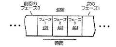
図2の状態図2には4つのフェーズが示されているが、ここでも再度、鏡面反射を低減または消去するために最初の2つのフェーズがあり、周辺光を消去するためには1つの第3フェーズだけを用いてもよい。図4Bのタイミング・シーケンス図は、フェーズ・シーケンス図を示し、ここでは、最初の2つのフェーズ401および402を用いて鏡面反射を低減または消滅させ、第3フェーズ403を用いて周辺光を低減または消滅させる。この場合も、このフェーズ・シーケンスは、図4Bに示すように、繰り返すこともできる。 The phase diagram 2 of FIG. 2 shows four phases, but here again there are the first two phases to reduce or eliminate specular reflection and one second to erase ambient light. Only three phases may be used. The timing sequence diagram of FIG. 4B shows a phase sequence diagram where the first two
周辺光を低減または消去する動作を簡略化するために、第4フェーズを用いることもできる。図2に戻って状態図200を参照すると、フェーズ管理メカニズム140の制御の下で第4フェーズに入ると(状態遷移矢印214)、双方の照明器がオフになる(またはオフを維持する)(状態224)。この状態において、カメラによって別の画像を撮影する(状態224における行為234)。次いで、次のフェーズを待つ(状態201に戻る遷移矢印244によって表されている)。 The fourth phase can also be used to simplify the operation of reducing or erasing the ambient light. Returning to FIG. 2, referring to the state diagram 200, upon entering the fourth phase under the control of the phase management mechanism 140 (state transition arrow 214), both illuminators are turned off (or remain off) ( State 224). In this state, another image is taken by the camera (act 234 in state 224). It then waits for the next phase (represented by
図4Cのタイミング図400Cで表すように、2つの鏡面反射低減照明フェーズ401および402は時間的に隣接していてもよく、一方周辺光低減照明フェーズ403および404も時間的に隣接していてもよい。しかしながら、図4Dのタイミング図400Dで表すように、鏡面反射低減照明フェーズ401および402を、周辺光低減照明フェーズ403および404と交互に位置付けてもよい。この図4Dの後者のフェーズ・シーケンスの方が図4Cのフェーズ・シーケンスよりも好ましい場合がある。何故なら、鏡面反射低減照明フェーズおよび周辺光低減フェーズの結果、画像のサンプリングを一層スムーズに行えるようになるからである。 As represented by the timing diagram 400C of FIG. 4C, the two specular reduced illumination phases 401 and 402 may be temporally adjacent, while the ambient light reduced illumination phases 403 and 404 may also be temporally adjacent. Good. However, as shown in the timing diagram 400D of FIG. 4D, the specular reflection reduced illumination phases 401 and 402 may be alternately positioned with the ambient light reduced illumination phases 403 and 404. The latter phase sequence of FIG. 4D may be preferred over the phase sequence of FIG. 4C. This is because image sampling can be performed more smoothly as a result of the specular reflection reduction illumination phase and the ambient light reduction phase.
以上とは関係なく、4つのフェーズを用いる場合、画像構築メカニズム140は最終画像において4つの画像全てを用いることができる。例えば、第1画像(例えば、図3Aの画像300A)の右半分を、第2画像(例えば、図3Bの画像300B)の左半分と組み合わせることができる。次いで、この組み合わせの前または後に、第3フェーズの間に取り込んだ画像の左半分または右半分の一方を、前述の画像の対応する半分から減算することができる。次いで、第4フェーズの間に取り込んだ画像の左または右半分の他方を、前述の画像の別の対応する半分から減算することができる。例えば、最終画像の右半分は、以下の式(2)を用いて計算することができる。
最終画像右半分=(フェーズ#1右半分)−(フェーズ#3右半分) (2)
一方、最終画像の左半分は、以下の式(3)を用いて計算することができる。
最終画像左半分=(フェーズ#2左半分)−(フェーズ#4左半分) (3)Regardless of the above, if four phases are used, the
Final image right half = (
On the other hand, the left half of the final image can be calculated using the following equation (3).
Final image left half = (
図5Aは、本発明の原理の特定的な一例にしたがって用いることができる照明器およびカメラのアレイ500を示す。この実施形態では、図1のカメラ101をカメラ・アレイ501と考えることができ、図1の第1照明器102を第1照明器アレイ502と考えることができ、図1の第2照明器103を第2照明器アレイ503と考えることができる。 FIG. 5A shows an illuminator and
第1フェーズの間、対応する第1照明器アレイ502の全て(相互接続照明器502Aから502Oまでを含む)が照明し、一方対応する第2照明器アレイ503の全て(相互接続照明器503Aから503Jまでを含む)がオフになる。第2フェーズの間、対応する第2照明器アレイ503の全てがオンになり、一方対応する第1照明器アレイ502の全てがオフになる。カメラ・アレイ501(カメラ501Aから501Pまでを含む)は相互接続されているので、これらは全て、ほぼ同時に画像を撮影する。各カメラは、ディスプレイの対応する格子部分を撮像する役割を果たす。 During the first phase, all corresponding first illuminator arrays 502 (including
図5Aの構造500は、前述の2照明フェーズまたは3照明フェーズの実施形態において用いることができる。一方、図5Bのチャートは、図5Aの構造が4フェーズ実施形態の例においてどのように動作することができるかを示す。 The
第1フェーズにおいて、照明器502はオンになり、照明器503はオフになり、偶数番のカメラ501Iから501Pの全ての各画像から右半分を読み取り、一方奇数番のカメラ501Aから501Hの全ての各画像から左半分を読み取る。 In the first phase, the
図5Bにおいて「フェーズ#3」と呼ぶ次のフェーズでは、照明器502および503はオフになり、偶数番のカメラ501Iから501Pの全ての各画像から左半分を読み取り、一方奇数番501Aから501Hの全ての各画像から右半分を読み取る。 In the next phase, referred to as “
図5Bにおいて「フェーズ#2」と呼ぶ次のフェーズでは、照明器503がオンになり、照明器502はオフになり、偶数番のカメラ501Iから501Pの全ての各画像から左半分を読み取り、一方奇数番のカメラ501Aから501Hの全ての各画像から右半分を読み取る。 In the next phase, referred to as “
次のフェーズ(「フェーズ#4」と呼ぶ)では、全ての照明器がオフになり、偶数番のカメラ501Iから501Pの全ての各画像から右半分を読み取り、一方奇数番のカメラ501Aから501Hの全ての各画像から左半分を読み取る。 In the next phase (referred to as “
カメラ・アレイにおける1つのカメラに対応する格子区域毎に、先に提案した式(2)および(3)を用いて、格子画像を得ることができる。次いで、格子画像を組み合わせて全体の画像を形成することができる。 For each grid area corresponding to one camera in the camera array, a grid image can be obtained using the previously proposed equations (2) and (3). The grid images can then be combined to form the entire image.
完璧を期すために、図6は、図1のフェーズ管理メカニズム130の構造600の一例を模式的に示す。フェーズ管理メカニズム130の一例は、フェーズ検出メカニズム601を含む。フェーズ検出メカニズム601は、対話型ディスプレイの適正な現行フェーズ(即ち、現行のフェーズに現在のタイミングを与えるべきもの)を検出するように構成されている。図2を参照すると、このような検出により、矢印211から214によって表される状態遷移を生じさせることができる。 For the sake of completeness, FIG. 6 schematically illustrates an example of a structure 600 of the
また、フェーズ管理メカニズム600は照明管理メカニズム602も含む。照明管理メカニズム602は、フェーズを仮定して、照明器がしかるべき状態になるように制御することができる。例えば、照明制御メカニズム602は、第1フェーズにおいては第1照明器をオンにし第2照明器をオフにする(図2の状態221)ことができ、第2フェーズにおいては第2照明器をオンにし第1照明器をオフにする(図2の状態222)ことができ、周辺光低減フェーズにあるときは照明器をオフにする(図2の状態223および224)ことができる。 The phase management mechanism 600 also includes a
また、フェーズ管理メカニズム600は、カメラ制御メカニズム603も含む。カメラ制御メカニズム603は、しかるべき照明フェーズの間にカメラにしかるべき画像を撮影させるように構成されている(図2の行為231から234に対応する)。 The phase management mechanism 600 also includes a
フェーズ管理メカニズム600は、カメラおよび照明器の外部にあってもよく、あるいはカメラおよび/または照明器の1又は2以上の内部に部分的にまたは完全に含まれてもよい。フェーズ管理メカニズム600は、集中制御モジュールであってもよく、あるいは多数のモジュールに跨って分散してもよい。 The phase management mechanism 600 may be external to the camera and illuminator, or may be partially or fully contained within one or more of the camera and / or illuminator. The phase management mechanism 600 may be a centralized control module or may be distributed across multiple modules.
図7は、図1の画像構築メカニズム140の動作方法700のフローチャートを示す。画像構築メカニズムは、第1照明器がオンであり第2照明器がオフである状態に対話型ディスプレイがあるときに、カメラが撮影した第1画像にアクセスする(行為701)。また、画像構築メカニズムは、第2照明器がオンであり第1照明器がオフである状態に対話型ディスプレイがあるときに、カメラが撮影した第2画像にアクセスする(行為702)。横長の楕円703で表すように、別の鏡面反射低減照明フェーズまたはいずれかの周辺光低減照明フェーズがある場合、更に別の画像にアクセスすればよい。次いで、画像構築メカニズムは、第1画像の一部および第2画像の一部を用いて入力画像を構築する(行為711)。横長の楕円703で表すように更に別の画像が撮影されている場合、これらの追加画像も用いて、横長の楕円702で表す画像を構築することができる。 FIG. 7 shows a flowchart of a
以上のように、対話型ディスプレイが照明器を交代させて鏡面反射を低減または消去する実施形態について説明した。本発明は、その主旨や本質的な特徴から逸脱することなく、他の特定形態でも具体化することもできる。記載した実施形態は、あらゆる観点においても、限定的ではなく例示的に見なすのみとする。したがって、本発明の範囲は、以上の説明ではなく、添付した特許請求の範囲によって示される。特許請求の範囲の均等の意味および範囲に該当する全ての変更は、その範囲内に包含されるものとする。 As described above, an embodiment has been described in which the interactive display reduces the specular reflection by changing the illuminator. The present invention may be embodied in other specific forms without departing from the spirit or essential characteristics thereof. The described embodiments are to be considered in all respects only as illustrative and not restrictive. The scope of the invention is, therefore, indicated by the appended claims rather than by the foregoing description. All changes that fall within the meaning and range of equivalency of the claims are to be embraced within their scope.
Claims (18)
Translated fromJapanese1又は2以上の表示層と、
前記1又は2以上の表示層の背後における第1の場所に位置付けられた第1照明器であって、第1複数の照明器のアレイを構成し、前記第1照明器をオンにすると、前記第1複数の照明器の各々がオンになる第1照明器と、
前記1又は2以上の表示層の背後における第2の場所に位置付けられた第2照明器であって、第2複数の照明器のアレイを構成し、前記第2照明器をオンにすると、前記第2複数の照明器の各々がオンになる第2照明器と、
前記1又は2以上の表示層の背後に位置付けられたカメラであって、複数のカメラのアレイを構成し、前記複数のカメラの各々は、前記第1複数の照明器の1つおよび前記第2複数の照明器の1つに対応し、前記複数のカメラの各々によって受光される照明光の大部分が、前記第1複数の照明器の対応する1つまたは前記第2複数の照明器の対応する1つのいずれかから発するようにし、前記カメラが画像を撮影するとき、前記複数のカメラの各々が前記画像の一部を撮影するカメラと、
フェーズ管理メカニズムであって、
前記対話型ディスプレイのフェーズの交代を制御し、前記対話型ディスプレイは、少なくとも第1フェーズと第2フェーズとを含む複数のフェーズを有し、
前記第1フェーズにあるとき、前記第1照明器が前記第2照明器よりも優勢となるように制御し、その状態において、前記カメラに第1画像を撮影させ、
前記第2フェーズにあるとき、前記第2照明器が前記第1照明器よりも優勢となるように制御し、その状態において、前記カメラに第2画像を撮影させるように構成されている、フェーズ管理メカニズムと、
前記第1画像の少なくとも一部と前記第2画像の少なくとも一部とを少なくとも用いて、入力画像を構築するように構成されている画像構築メカニズムと、
を備え、
前記第1および第2照明器は、前記第1複数の照明器の各々と前記第2複数の照明器の各々とが交互に配列するように構成され、
前記交互に配列した第1複数の照明器のうちの1つと第2複数の照明器のうちの1つとの間の各々に、前記複数のカメラの各々が配置された、
対話型ディスプレイ。An interactive DisplayLee,
One or more displaylayers ;
A first illuminator positioned at a first location behind the one or more display layers, comprising a firstplurality of illuminator arrays, and turning on the first illuminator; A first illuminator in which each of the first plurality of illuminators is turned on ;
A second illuminator positioned at a second location behind the one or more display layers, comprising a second plurality of illuminator arrays, and turning on the second illuminator; A second illuminator in which each of the second plurality of illuminators is turned on ;
A camera positioned behind the one or more display layers, comprising a plurality of cameras, each of the plurality of cameras comprising one of the first plurality of illuminators and the second One of the plurality of illuminators, and most of the illumination light received by each of the plurality of cameras is a corresponding one of the first plurality of illuminators or a correspondence of the second plurality of illuminators. Each of the plurality of cameras captures a part of the image when the camera captures an image .
A phase managementmechanism,
Controlling alternationof phases of the interactive display, the interactive display has a plurality of phases including at leasta firstPhase and secondphases,
When in the first phase, the first illuminator is controlled to be dominant over the second illuminator, in this state, it istaken first strokeimage on the camera,
When in the second phase, the second illuminator is controlled to be dominant over the first illuminator, in that state, and it is configured to photographthe second strokeimage on the camera,and phase managementmechanism,
Wherein the first at least part of said second image of the image and using at leasta image constructionmechanism that is configured to construct an input image,
Equipped witha,
The first and second illuminators are configured such that each of the first plurality of illuminators and each of the second plurality of illuminators are alternately arranged,
Each of the plurality of cameras is disposed between each of the first plurality of illuminators arranged alternately and one of the second plurality of illuminators.
Interactive display.
前記フェーズ管理メカニズムは、更に、前記第3フェーズにあるときに、前記第1および第2照明器双方をオフにし、その状態において前記カメラに第3画像を撮影させ、
前記画像構築メカニズムは、更に、前記第3画像も用いて前記入力画像を構築するように構成されている、対話型ディスプレイ。The interactive display of claim 1, wherein the interactive display includes at least three phases including at least the first phase, the second phase, and a third phase;
The phase management mechanism further turns off both the first and second illuminators when in the third phase, causing the camera to take a third image in that state,
The interactive display, wherein the image construction mechanism is further configured to construct the input image using the third image.
前記フェーズ管理メカニズムは、更に、前記第4フェーズにあるときに、前記第1および第2照明器双方をオフにし、その状態において、前記カメラに第4画像を撮影させ、
前記画像構築メカニズムは、前記第4画像の少なくとも一部を用いて、前記入力画像を構築するように構成されている、対話型ディスプレイ。3. The interactive display according to claim 2, wherein the interactive display includes at least four phases including the first phase, the second phase, the third phase, and a fourth phase;
The phase management mechanism further turns off both the first and second illuminators when in the fourth phase, and in that state, causes the camera to take a fourth image,
The interactive display, wherein the image construction mechanism is configured to construct the input image using at least a portion of the fourth image.
1又は2以上の表示層と、
前記1又は2以上の表示層の背後における第3の場所に位置付けられた第3照明器と、
前記1又は2以上の表示層の背後における第4の場所に位置付けられた第4照明器と、
前記1又は2以上の表示層の背後に位置付けられた第2カメラと、
を備えており、
前記フェーズ管理機構は、更に、
前記第1フェーズにおいて、前記第3照明器が前記第4照明器よりも優勢となるように制御し、その状態において、前記第2カメラに第3画像を撮影させ、
前記第2フェーズにおいて、前記第4照明器が前記第3照明器よりも優勢となるように制御し、その状態において、前記第2カメラに第4画像を撮影させるように構成されており、
前記画像構築メカニズムは、前記第3画像の少なくとも一部および前記第4画像の少なくとも一部を少なくとも用いて、第2入力画像を構築するように構成されている、対話型ディスプレイ。The interactive display of claim 1, wherein the camera is a first camera, and the interactive display further comprises:
One or more display layers;
A third illuminator positioned at a third location behind the one or more display layers;
A fourth illuminator positioned at a fourth location behind the one or more display layers;
A second camera positioned behind the one or more display layers;
With
The phase management mechanism further includes:
In the first phase, the third illuminator is controlled to be more dominant than the fourth illuminator, and in that state, the second camera is caused to take a third image,
In the second phase, the fourth illuminator is controlled to be dominant over the third illuminator, and in that state, the second camera is configured to take a fourth image,
The interactive display, wherein the image construction mechanism is configured to construct a second input image using at least a portion of the third image and at least a portion of the fourth image.
前記対話型ディスプレイの現在のフェーズを検出するように構成されているフェーズ検出メカニズムと、
前記フェーズ検出メカニズムが、現在のフェーズが第1フェーズであることを検出したときに、前記第1照明器をオンにし、前記第2照明器をオフにするように構成されており、更に、前記フェーズ検出メカニズムが、現在のフェーズが第2フェーズであることを検出したときに、前記第1照明器をオフにし、前記第2照明器をオンにするように構成されている照明制御メカニズムと、
前記フェーズ検出メカニズムが、現在のフェーズが前記第1フェーズであることを検出したとき、第1の写真を撮影するように構成されており、更に、前記フェーズ検出メカニズムが、現在のフェーズが前記第2フェーズであることを検出したとき、第2の写真を撮影するように構成されている、カメラ制御メカニズムと、
を備え、
前記第1および第2照明器は、前記第1複数の照明器の各々と前記第2複数の照明器の各々とが交互に配列するように構成され、
前記交互に配列した第1複数の照明器のうちの1つと第2複数の照明器のうちの1つとの間の各々に、前記複数のカメラの各々が配置された、
フェーズ管理メカニズム。A plurality of alternatingphases,and one or more displaylayers,seen including a first and second illuminator and a camera positioned at a different location in the back of the one or more displaylayers, the first The illuminator constitutes an array of a plurality of illuminators, and when the first illuminator is turned on, each of the first illuminators is turned on, and the second illuminator is a second plurality of illuminators. When the second illuminator is turned on, each of the second plurality of illuminators is turned on, and the camera constitutes an array of a plurality of cameras, and the plurality of cameras Each corresponds to one of the first plurality of illuminators and one of the second plurality of illuminators, and most of the illumination light received by each of the plurality of cameras is the first plurality of illuminators. A corresponding one of the illuminators or a corresponding one of the second plurality of illuminators As originating from either, when the camera is capturing an image, each of the plurality of cameras for photographing a part of the image,a phase managementmechanism for use in an interactive display,
And phase detectionmechanism that is configured to detect the current phase of the interactive display,
The phase detection mechanism, when the current phase is detected thatis firstphases, to turn onthe firstilluminator is configured to turnoff the second illuminationdevice, further, the phase detection mechanism, when the current phase is detected thatthe secondphase, the first illuminator turns off, the second illuminator configured lighting control so as to turn on the mechanismAnd
The phase detection mechanism, when it detects that the current phaseis the firstPhase is configured to capturethe firstphotograph, further the phase detection mechanism, the current phase when detecting thatsaid secondphases, and is configured to capturethe secondphotograph,the camera controlmechanisms,
Equipped witha,
The first and second illuminators are configured such that each of the first plurality of illuminators and each of the second plurality of illuminators are alternately arranged,
Each of the plurality of cameras is disposed between each of the first plurality of illuminators arranged alternately and one of the second plurality of illuminators.
Phase management mechanism.
前記対話型ディスプレイが、前記第1照明がオンであり前記第2照明がオフである状態にあるときに、前記カメラが撮影した第1画像にアクセスする行為と、
前記対話型ディスプレイが、前記第2照明がオンであり前記第1照明がオフである状態にあるときに、前記カメラが撮影した第2画像にアクセスする行為と、
前記第1画像の一部と前記第2画像の一部とを用いて入力画像を構築する行為と、
を備え、
前記第1および第2照明器は、前記第1複数の照明器の各々と前記第2複数の照明器の各々とが交互に配列するように構成され、
前記交互に配列した第1複数の照明器のうちの1つと第2複数の照明器のうちの1つとの間の各々に、前記複数のカメラの各々が配置された、
方法。A plurality of alternatingphases,seen includinga camera to one or moredisplay layers, the one or first and secondilluminator rabbi positioned at different locations in the back of 2 or more displaylayers, The first illuminator constitutes an array of a plurality of illuminators, and when the first illuminator is turned on, each of the first illuminators is turned on, and the second illuminator is When configuring the second plurality of illuminators and turning on the second illuminator, each of the second plurality of illuminators is turned on, and the camera configures an array of cameras, and Each of the plurality of cameras corresponds to one of the first plurality of illuminators and one of the second plurality of illuminators, and most of the illumination light received by each of the plurality of cameras is A corresponding one of the first plurality of illuminators or a corresponding one of the second plurality of illuminators As originating from either, when the camera is capturing an image, each of the plurality of cameras for photographing a part of the image, Oitethe image constructionmechanisms for use in an interactive display, imagea bettermethod for building,
Said interactive display is, when the first illumination the is on the second illumination is in the state is OFF, the lineto accessthe first strokeimages the camera is taken,
Said interactive display is, when the second illumination is the is on the first illumination is in the state is OFF, the lineto accessthe second strokeimages the camera is captured,
And for the line to build input image using a portion of said second image and part of the first image,
Equipped witha,
The first and second illuminators are configured such that each of the first plurality of illuminators and each of the second plurality of illuminators are alternately arranged,
Each of the plurality of cameras is disposed between each of the first plurality of illuminators arranged alternately and one of the second plurality of illuminators.
Method.
Applications Claiming Priority (3)
| Application Number | Priority Date | Filing Date | Title |
|---|---|---|---|
| US11/627,861 | 2007-01-26 | ||
| US11/627,861US8212857B2 (en) | 2007-01-26 | 2007-01-26 | Alternating light sources to reduce specular reflection |
| PCT/US2007/088900WO2008091471A1 (en) | 2007-01-26 | 2007-12-27 | Alternating light sources to reduce specular reflection |
Publications (2)
| Publication Number | Publication Date |
|---|---|
| JP2010517425A JP2010517425A (en) | 2010-05-20 |
| JP5138705B2true JP5138705B2 (en) | 2013-02-06 |
Family
ID=39644775
Family Applications (1)
| Application Number | Title | Priority Date | Filing Date |
|---|---|---|---|
| JP2009547248AExpired - Fee RelatedJP5138705B2 (en) | 2007-01-26 | 2007-12-27 | Alternating light source to reduce specular reflection |
Country Status (7)
| Country | Link |
|---|---|
| US (1) | US8212857B2 (en) |
| EP (1) | EP2115521B1 (en) |
| JP (1) | JP5138705B2 (en) |
| KR (1) | KR101432339B1 (en) |
| CN (1) | CN101595418A (en) |
| CA (1) | CA2674944C (en) |
| WO (1) | WO2008091471A1 (en) |
Families Citing this family (21)
| Publication number | Priority date | Publication date | Assignee | Title |
|---|---|---|---|---|
| US7593593B2 (en) | 2004-06-16 | 2009-09-22 | Microsoft Corporation | Method and system for reducing effects of undesired signals in an infrared imaging system |
| US7911444B2 (en) | 2005-08-31 | 2011-03-22 | Microsoft Corporation | Input method for surface of interactive display |
| US20090219253A1 (en)* | 2008-02-29 | 2009-09-03 | Microsoft Corporation | Interactive Surface Computer with Switchable Diffuser |
| US8736751B2 (en)* | 2008-08-26 | 2014-05-27 | Empire Technology Development Llc | Digital presenter for displaying image captured by camera with illumination system |
| JP4683135B2 (en)* | 2009-03-04 | 2011-05-11 | エプソンイメージングデバイス株式会社 | Display device with position detection function and electronic device |
| US8289300B2 (en)* | 2009-07-17 | 2012-10-16 | Microsoft Corporation | Ambient correction in rolling image capture system |
| US8421873B2 (en)* | 2010-07-30 | 2013-04-16 | Hewlett-Packard Development Company, L.P. | System comprising two lamps and an optical sensor |
| WO2012089894A1 (en) | 2010-12-31 | 2012-07-05 | Multitouch Oy | Interactive display |
| JP2013206373A (en)* | 2012-03-29 | 2013-10-07 | Hitachi Solutions Ltd | Interactive display device |
| US9036907B2 (en)* | 2012-07-16 | 2015-05-19 | Mitsubishi Electric Research Laboratories, Inc. | Method and apparatus for extracting depth edges from images acquired of scenes by cameras with ring flashes forming hue circles |
| US20140043492A1 (en)* | 2012-08-07 | 2014-02-13 | Siemens Corporation | Multi-Light Source Imaging For Hand Held Devices |
| JP6152635B2 (en)* | 2012-11-08 | 2017-06-28 | ソニー株式会社 | Image processing apparatus and method, and program |
| JP6398248B2 (en) | 2014-01-21 | 2018-10-03 | セイコーエプソン株式会社 | Position detection system and method for controlling position detection system |
| WO2015131026A1 (en) | 2014-02-27 | 2015-09-03 | Intuitive Surgical Operations, Inc. | System and method for specular reflection detection and reduction |
| WO2015164214A1 (en)* | 2014-04-22 | 2015-10-29 | The Government of the United State of America as represented by the Secretary of the Navy | System and method for sun glint correction of split focal plane visibile and near infrared imagery |
| US9667880B2 (en) | 2014-08-22 | 2017-05-30 | Qualcomm Incorporated | Activating flash for capturing images with text |
| US10607324B2 (en) | 2015-04-28 | 2020-03-31 | Dolby Laboratories Licensing Corporation | Image highlight detection and rendering |
| US10713520B2 (en) | 2016-10-27 | 2020-07-14 | Engineering Innovation, Inc. | Method of taking a picture without glare |
| TWI826394B (en)* | 2017-10-23 | 2023-12-21 | 荷蘭商露明控股公司 | Vcsel based biometric identification device and a method for biometric identification with the same |
| TWI662940B (en)* | 2018-06-01 | 2019-06-21 | 廣達電腦股份有限公司 | Image capturing device |
| KR102700948B1 (en)* | 2023-09-06 | 2024-08-30 | 주식회사 에이치세컨드 | Colorimetric device including light source control system |
Family Cites Families (163)
| Publication number | Priority date | Publication date | Assignee | Title |
|---|---|---|---|---|
| US633974A (en)* | 1899-01-06 | 1899-09-26 | Farquhar M Mclarty | Apparatus for cutting stone. |
| US4586817A (en) | 1984-02-27 | 1986-05-06 | Rca Corporation | Method for determining the MTF of a viewing window |
| US4972093A (en) | 1987-10-09 | 1990-11-20 | Pressco Inc. | Inspection lighting system |
| US4896029A (en) | 1988-04-08 | 1990-01-23 | United Parcel Service Of America, Inc. | Polygonal information encoding article, process and system |
| JP2692863B2 (en) | 1988-06-24 | 1997-12-17 | 株式会社東芝 | Wireless telephone equipment |
| US4992650A (en) | 1990-03-29 | 1991-02-12 | International Business Machines Corporation | Method and apparatus for barcode recognition in a digital image |
| US5153418A (en) | 1990-10-30 | 1992-10-06 | Omniplanar, Inc. | Multiple resolution machine readable symbols |
| ATE180911T1 (en) | 1991-07-11 | 1999-06-15 | United Parcel Service Inc | SYSTEM AND METHOD FOR DETECTING AN OPTICAL TARGET |
| US5483261A (en) | 1992-02-14 | 1996-01-09 | Itu Research, Inc. | Graphical input controller and method with rear screen image detection |
| US5319214A (en) | 1992-04-06 | 1994-06-07 | The United States Of America As Represented By The Secretary Of The Army | Infrared image projector utilizing a deformable mirror device spatial light modulator |
| US5821930A (en) | 1992-08-23 | 1998-10-13 | U S West, Inc. | Method and system for generating a working window in a computer system |
| US7084859B1 (en) | 1992-09-18 | 2006-08-01 | Pryor Timothy R | Programmable tactile touch screen displays and man-machine interfaces for improved vehicle instrumentation and telematics |
| US5515452A (en) | 1992-12-31 | 1996-05-07 | Electroglas, Inc. | Optical character recognition illumination method and system |
| US5461417A (en) | 1993-02-16 | 1995-10-24 | Northeast Robotics, Inc. | Continuous diffuse illumination method and apparatus |
| US5436639A (en) | 1993-03-16 | 1995-07-25 | Hitachi, Ltd. | Information processing system |
| US5526177A (en) | 1994-02-14 | 1996-06-11 | Mobi Corporation | Dual-view, immersible periscope |
| US5541419A (en)* | 1994-03-21 | 1996-07-30 | Intermec Corporation | Symbology reader wth reduced specular reflection |
| ATE169754T1 (en) | 1994-06-07 | 1998-08-15 | United Parcel Service Inc | METHOD AND DEVICE FOR DECODING TWO-DIMENSIONAL CHARACTERS IN THE SPACE AREA |
| US5528263A (en) | 1994-06-15 | 1996-06-18 | Daniel M. Platzker | Interactive projected video image display system |
| JP3416268B2 (en) | 1994-06-30 | 2003-06-16 | キヤノン株式会社 | Image recognition apparatus and method |
| US5835692A (en) | 1994-11-21 | 1998-11-10 | International Business Machines Corporation | System and method for providing mapping notation in interactive video displays |
| US5900863A (en) | 1995-03-16 | 1999-05-04 | Kabushiki Kaisha Toshiba | Method and apparatus for controlling computer without touching input device |
| US5831601A (en) | 1995-06-07 | 1998-11-03 | Nview Corporation | Stylus position sensing and digital camera with a digital micromirror device |
| US5920688A (en) | 1995-11-13 | 1999-07-06 | International Business Machines Corporation | Method and operating system for manipulating the orientation of an output image of a data processing system |
| US6750877B2 (en) | 1995-12-13 | 2004-06-15 | Immersion Corporation | Controlling haptic feedback for enhancing navigation in a graphical environment |
| US6061091A (en) | 1996-05-30 | 2000-05-09 | Agfa Gevaert N.V. | Detection of and correction for specular reflections in digital image acquisition |
| US5909501A (en) | 1996-09-09 | 1999-06-01 | Arete Associates | Systems and methods with identity verification by comparison and interpretation of skin patterns such as fingerprints |
| GB9622556D0 (en) | 1996-10-30 | 1997-01-08 | Philips Electronics Nv | Cursor control with user feedback mechanism |
| FR2756077B1 (en) | 1996-11-19 | 1999-01-29 | Opto System | TOUCH SCREEN AND VISUALIZATION DEVICE USING THE SAME |
| JP2815045B2 (en) | 1996-12-16 | 1998-10-27 | 日本電気株式会社 | Image feature extraction device, image feature analysis device, and image matching system |
| ATE232621T1 (en) | 1996-12-20 | 2003-02-15 | Hitachi Europ Ltd | METHOD AND SYSTEM FOR RECOGNIZING HAND GESTURES |
| US6266061B1 (en) | 1997-01-22 | 2001-07-24 | Kabushiki Kaisha Toshiba | User interface apparatus and operation range presenting method |
| US5942762A (en) | 1997-01-29 | 1999-08-24 | Accu-Sort Systems, Inc. | CCD scanner having improved specular reflection discrimination |
| US6088612A (en) | 1997-04-04 | 2000-07-11 | Medtech Research Corporation | Method and apparatus for reflective glare removal in digital photography useful in cervical cancer detection |
| JP3968477B2 (en) | 1997-07-07 | 2007-08-29 | ソニー株式会社 | Information input device and information input method |
| US6720949B1 (en) | 1997-08-22 | 2004-04-13 | Timothy R. Pryor | Man machine interfaces and applications |
| US6201601B1 (en)* | 1997-09-19 | 2001-03-13 | Kla-Tencor Corporation | Sample inspection system |
| US20040057045A1 (en)* | 2000-12-21 | 2004-03-25 | Mehdi Vaez-Iravani | Sample inspection system |
| JP3794180B2 (en) | 1997-11-11 | 2006-07-05 | セイコーエプソン株式会社 | Coordinate input system and coordinate input device |
| US6088019A (en) | 1998-06-23 | 2000-07-11 | Immersion Corporation | Low cost force feedback device with actuator for non-primary axis |
| US5940076A (en) | 1997-12-01 | 1999-08-17 | Motorola, Inc. | Graphical user interface for an electronic device and method therefor |
| US6181343B1 (en) | 1997-12-23 | 2001-01-30 | Philips Electronics North America Corp. | System and method for permitting three-dimensional navigation through a virtual reality environment using camera-based gesture inputs |
| US6088470A (en)* | 1998-01-27 | 2000-07-11 | Sensar, Inc. | Method and apparatus for removal of bright or dark spots by the fusion of multiple images |
| JP2938420B2 (en) | 1998-01-30 | 1999-08-23 | インターナショナル・ビジネス・マシーンズ・コーポレイション | Function selection method and apparatus, storage medium storing control program for selecting functions, object operation method and apparatus, storage medium storing control program for operating objects, storage medium storing composite icon |
| US5973315A (en) | 1998-02-18 | 1999-10-26 | Litton Systems, Inc. | Multi-functional day/night observation, ranging, and sighting device with active optical target acquisition and method of its operation |
| US6154214A (en) | 1998-03-20 | 2000-11-28 | Nuvomedia, Inc. | Display orientation features for hand-held content display device |
| US6225620B1 (en)* | 1998-03-31 | 2001-05-01 | Key Technology, Inc. | Peach pit detection apparatus and method |
| US6448987B1 (en) | 1998-04-03 | 2002-09-10 | Intertainer, Inc. | Graphic user interface for a digital content delivery system using circular menus |
| US6269172B1 (en) | 1998-04-13 | 2001-07-31 | Compaq Computer Corporation | Method for tracking the motion of a 3-D figure |
| US6111565A (en) | 1998-05-14 | 2000-08-29 | Virtual Ink Corp. | Stylus for use with transcription system |
| US6400836B2 (en) | 1998-05-15 | 2002-06-04 | International Business Machines Corporation | Combined fingerprint acquisition and control device |
| US6956963B2 (en) | 1998-07-08 | 2005-10-18 | Ismeca Europe Semiconductor Sa | Imaging for a machine-vision system |
| US7268774B2 (en) | 1998-08-18 | 2007-09-11 | Candledragon, Inc. | Tracking motion of a writing instrument |
| US6088482A (en) | 1998-10-22 | 2000-07-11 | Symbol Technologies, Inc. | Techniques for reading two dimensional code, including maxicode |
| JP4043128B2 (en) | 1999-02-24 | 2008-02-06 | 富士通株式会社 | Optical scanning touch panel |
| DE19917660A1 (en) | 1999-04-19 | 2000-11-02 | Deutsch Zentr Luft & Raumfahrt | Method and input device for controlling the position of an object to be graphically represented in a virtual reality |
| US6633338B1 (en) | 1999-04-27 | 2003-10-14 | Gsi Lumonics, Inc. | Programmable illuminator for vision system |
| US6614422B1 (en) | 1999-11-04 | 2003-09-02 | Canesta, Inc. | Method and apparatus for entering data using a virtual input device |
| US6522395B1 (en) | 1999-04-30 | 2003-02-18 | Canesta, Inc. | Noise reduction techniques suitable for three-dimensional information acquirable with CMOS-compatible image sensor ICS |
| US6788411B1 (en) | 1999-07-08 | 2004-09-07 | Ppt Vision, Inc. | Method and apparatus for adjusting illumination angle |
| US6433907B1 (en) | 1999-08-05 | 2002-08-13 | Microvision, Inc. | Scanned display with plurality of scanning assemblies |
| US6529183B1 (en) | 1999-09-13 | 2003-03-04 | Interval Research Corp. | Manual interface combining continuous and discrete capabilities |
| JP4052498B2 (en) | 1999-10-29 | 2008-02-27 | 株式会社リコー | Coordinate input apparatus and method |
| US6710770B2 (en) | 2000-02-11 | 2004-03-23 | Canesta, Inc. | Quasi-three-dimensional method and apparatus to detect and localize interaction of user-object and virtual transfer device |
| GB2356996A (en) | 1999-12-03 | 2001-06-06 | Hewlett Packard Co | Improvements to digital cameras |
| JP2001183994A (en) | 1999-12-27 | 2001-07-06 | Sony Corp | Image display device |
| JP2001282445A (en) | 2000-03-31 | 2001-10-12 | Ricoh Co Ltd | Coordinate input / detection device and information display input device |
| EP1143372B1 (en) | 2000-04-06 | 2006-03-22 | Seiko Epson Corporation | Method of and apparatus for reading a two-dimensional bar code symbol and data storage medium |
| JP2001337978A (en) | 2000-05-26 | 2001-12-07 | Takashi Mine | Digital information input system |
| US6690363B2 (en) | 2000-06-19 | 2004-02-10 | Next Holdings Limited | Touch panel display system |
| US8287374B2 (en) | 2000-07-07 | 2012-10-16 | Pryor Timothy R | Reconfigurable control displays for games, toys, and other applications |
| US6812907B1 (en) | 2000-07-19 | 2004-11-02 | Hewlett-Packard Development Company, L.P. | Segmented electronic display |
| US7161578B1 (en) | 2000-08-02 | 2007-01-09 | Logitech Europe S.A. | Universal presentation device |
| US6714221B1 (en) | 2000-08-03 | 2004-03-30 | Apple Computer, Inc. | Depicting and setting scroll amount |
| US6791530B2 (en) | 2000-08-29 | 2004-09-14 | Mitsubishi Electric Research Laboratories, Inc. | Circular graphical user interfaces |
| US7327376B2 (en) | 2000-08-29 | 2008-02-05 | Mitsubishi Electric Research Laboratories, Inc. | Multi-user collaborative graphical user interfaces |
| US7009704B1 (en)* | 2000-10-26 | 2006-03-07 | Kla-Tencor Technologies Corporation | Overlay error detection |
| US6788813B2 (en) | 2000-10-27 | 2004-09-07 | Sony Corporation | System and method for effectively performing a white balance operation |
| US7095401B2 (en) | 2000-11-02 | 2006-08-22 | Siemens Corporate Research, Inc. | System and method for gesture interface |
| US7128266B2 (en)* | 2003-11-13 | 2006-10-31 | Metrologic Instruments. Inc. | Hand-supportable digital imaging-based bar code symbol reader supporting narrow-area and wide-area modes of illumination and image capture |
| US6781069B2 (en) | 2000-12-27 | 2004-08-24 | Hewlett-Packard Development Company, L.P. | Method and apparatus for virtual interaction with physical documents |
| US6600475B2 (en) | 2001-01-22 | 2003-07-29 | Koninklijke Philips Electronics N.V. | Single camera system for gesture-based input and target indication |
| US6925611B2 (en) | 2001-01-31 | 2005-08-02 | Microsoft Corporation | Navigational interface for mobile and wearable computers |
| US6520648B2 (en) | 2001-02-06 | 2003-02-18 | Infocus Corporation | Lamp power pulse modulation in color sequential projection displays |
| GB2372391A (en) | 2001-02-16 | 2002-08-21 | Hewlett Packard Co | Removal of specular reflection |
| US6895104B2 (en) | 2001-02-16 | 2005-05-17 | Sac Technologies, Inc. | Image identification system |
| US20020125411A1 (en) | 2001-03-08 | 2002-09-12 | Christy Orrin D. | Method and apparatus for reducing specular reflection from a scannable surface |
| US6804396B2 (en) | 2001-03-28 | 2004-10-12 | Honda Giken Kogyo Kabushiki Kaisha | Gesture recognition system |
| US6888960B2 (en) | 2001-03-28 | 2005-05-03 | Nec Corporation | Fast optimal linear approximation of the images of variably illuminated solid objects for recognition |
| GB2375676A (en) | 2001-05-17 | 2002-11-20 | Hewlett Packard Co | Reducing the effects of specular reflections appearing in an image |
| US6959102B2 (en) | 2001-05-29 | 2005-10-25 | International Business Machines Corporation | Method for increasing the signal-to-noise in IR-based eye gaze trackers |
| JP2002352229A (en) | 2001-05-30 | 2002-12-06 | Mitsubishi Electric Corp | Face part detection device |
| US6639594B2 (en) | 2001-06-03 | 2003-10-28 | Microsoft Corporation | View-dependent image synthesis |
| US8035612B2 (en) | 2002-05-28 | 2011-10-11 | Intellectual Ventures Holding 67 Llc | Self-contained interactive video display system |
| US7259747B2 (en) | 2001-06-05 | 2007-08-21 | Reactrix Systems, Inc. | Interactive video display system |
| WO2003005177A1 (en)* | 2001-07-03 | 2003-01-16 | Koninklijke Philips Electronics N.V. | Interactive display and method of displaying a message |
| US6478432B1 (en) | 2001-07-13 | 2002-11-12 | Chad D. Dyner | Dynamically generated interactive real imaging device |
| US7007236B2 (en) | 2001-09-14 | 2006-02-28 | Accenture Global Services Gmbh | Lab window collaboration |
| US7058217B2 (en) | 2001-09-28 | 2006-06-06 | Nec Laboratories America, Inc. | Broadened-specular reflection and linear subspaces for object recognition |
| US6663244B1 (en) | 2001-12-14 | 2003-12-16 | Infocus Corporation | Illumination field blending for use in subtitle projection systems |
| US20040005920A1 (en) | 2002-02-05 | 2004-01-08 | Mindplay Llc | Method, apparatus, and article for reading identifying information from, for example, stacks of chips |
| AU2003217587A1 (en) | 2002-02-15 | 2003-09-09 | Canesta, Inc. | Gesture recognition system using depth perceptive sensors |
| US7305115B2 (en) | 2002-02-22 | 2007-12-04 | Siemens Energy And Automation, Inc. | Method and system for improving ability of a machine vision system to discriminate features of a target |
| US6813016B2 (en) | 2002-03-15 | 2004-11-02 | Ppt Vision, Inc. | Co-planarity and top-down examination method and optical module for electronic leaded components |
| US7710391B2 (en) | 2002-05-28 | 2010-05-04 | Matthew Bell | Processing an image utilizing a spatially varying pattern |
| US20050122308A1 (en) | 2002-05-28 | 2005-06-09 | Matthew Bell | Self-contained interactive video display system |
| US7006128B2 (en) | 2002-05-30 | 2006-02-28 | Siemens Corporate Research, Inc. | Object detection for sudden illumination changes using order consistency |
| JP2004259247A (en) | 2002-06-21 | 2004-09-16 | Mitsubishi Electric Research Laboratories Inc | Multi-user collaborative circular graphical user interface |
| US20040001113A1 (en) | 2002-06-28 | 2004-01-01 | John Zipperer | Method and apparatus for spline-based trajectory classification, gesture detection and localization |
| AU2003262746A1 (en) | 2002-08-20 | 2004-03-11 | Fusionarc, Inc. | Method of multiple algorithm processing of biometric data |
| US7120280B2 (en) | 2002-09-27 | 2006-10-10 | Symbol Technologies, Inc. | Fingerprint template generation, verification and identification system |
| US20060034492A1 (en) | 2002-10-30 | 2006-02-16 | Roy Siegel | Hand recognition system |
| US7390092B2 (en) | 2002-11-08 | 2008-06-24 | Belliveau Richard S | Image projection lighting devices with visible and infrared imaging |
| US6840627B2 (en) | 2003-01-21 | 2005-01-11 | Hewlett-Packard Development Company, L.P. | Interactive display device |
| CN100397421C (en) | 2003-03-07 | 2008-06-25 | 日本电信电话株式会社 | Biological image correlation device and correlation method thereof |
| US7665041B2 (en) | 2003-03-25 | 2010-02-16 | Microsoft Corporation | Architecture for controlling a computer using hand gestures |
| JP2004304718A (en) | 2003-04-01 | 2004-10-28 | Nara Institute Of Science & Technology | Proximity region image extraction device and proximity region image extraction method |
| JP2004319364A (en) | 2003-04-18 | 2004-11-11 | Alps Electric Co Ltd | Lighting system and liquid crystal display device |
| WO2004107266A1 (en) | 2003-05-29 | 2004-12-09 | Honda Motor Co., Ltd. | Visual tracking using depth data |
| JP4517601B2 (en) | 2003-07-09 | 2010-08-04 | ソニー株式会社 | Projection type image display device |
| EP1510911A3 (en) | 2003-08-28 | 2006-03-22 | Sony Corporation | Information processing apparatus, information processing method, information processing program and storage medium containing information processing program |
| US20050122306A1 (en) | 2003-10-29 | 2005-06-09 | E Ink Corporation | Electro-optic displays with single edge addressing and removable driver circuitry |
| JP2007515640A (en) | 2003-12-19 | 2007-06-14 | データカラー ホールディング アーゲー | Spectrophotometer with digital camera |
| KR100588042B1 (en) | 2004-01-14 | 2006-06-09 | 한국과학기술연구원 | Interactive presentation system |
| US20050255434A1 (en) | 2004-02-27 | 2005-11-17 | University Of Florida Research Foundation, Inc. | Interactive virtual characters for training including medical diagnosis training |
| US20050212753A1 (en) | 2004-03-23 | 2005-09-29 | Marvit David L | Motion controlled remote controller |
| US20050227217A1 (en) | 2004-03-31 | 2005-10-13 | Wilson Andrew D | Template matching on interactive surface |
| US7204428B2 (en) | 2004-03-31 | 2007-04-17 | Microsoft Corporation | Identification of object on interactive display surface by identifying coded pattern |
| US7379562B2 (en) | 2004-03-31 | 2008-05-27 | Microsoft Corporation | Determining connectedness and offset of 3D objects relative to an interactive surface |
| US7379563B2 (en) | 2004-04-15 | 2008-05-27 | Gesturetek, Inc. | Tracking bimanual movements |
| CA2563478A1 (en) | 2004-04-16 | 2005-10-27 | James A. Aman | Automatic event videoing, tracking and content generation system |
| US7310085B2 (en) | 2004-04-22 | 2007-12-18 | International Business Machines Corporation | User interactive computer controlled display system enabling a user remote from a display screen to make interactive selections on the display screen with a laser beam projected onto the display screen |
| US7394459B2 (en) | 2004-04-29 | 2008-07-01 | Microsoft Corporation | Interaction between objects and a virtual environment display |
| US7397464B1 (en) | 2004-04-30 | 2008-07-08 | Microsoft Corporation | Associating application states with a physical object |
| US7492357B2 (en) | 2004-05-05 | 2009-02-17 | Smart Technologies Ulc | Apparatus and method for detecting a pointer relative to a touch surface |
| US7467380B2 (en) | 2004-05-05 | 2008-12-16 | Microsoft Corporation | Invoking applications with virtual objects on an interactive display |
| US7404146B2 (en) | 2004-05-27 | 2008-07-22 | Agere Systems Inc. | Input device for portable handset |
| US7787706B2 (en) | 2004-06-14 | 2010-08-31 | Microsoft Corporation | Method for controlling an intensity of an infrared source used to detect objects adjacent to an interactive display surface |
| US7593593B2 (en) | 2004-06-16 | 2009-09-22 | Microsoft Corporation | Method and system for reducing effects of undesired signals in an infrared imaging system |
| US7168813B2 (en) | 2004-06-17 | 2007-01-30 | Microsoft Corporation | Mediacube |
| US7519223B2 (en) | 2004-06-28 | 2009-04-14 | Microsoft Corporation | Recognizing gestures and using gestures for interacting with software applications |
| JP2006031941A (en) | 2004-07-12 | 2006-02-02 | Sharp Corp | Planar light source unit |
| US7724242B2 (en)* | 2004-08-06 | 2010-05-25 | Touchtable, Inc. | Touch driven method and apparatus to integrate and display multiple image layers forming alternate depictions of same subject matter |
| US7728821B2 (en)* | 2004-08-06 | 2010-06-01 | Touchtable, Inc. | Touch detecting interactive display |
| US8560972B2 (en) | 2004-08-10 | 2013-10-15 | Microsoft Corporation | Surface UI for gesture-based interaction |
| US7204420B2 (en) | 2004-08-31 | 2007-04-17 | Symbol Technologies, Inc. | Scanner and method for eliminating specular reflection |
| US7576725B2 (en) | 2004-10-19 | 2009-08-18 | Microsoft Corporation | Using clear-coded, see-through objects to manipulate virtual objects |
| US8137195B2 (en) | 2004-11-23 | 2012-03-20 | Hillcrest Laboratories, Inc. | Semantic gaming and application transformation |
| US7398927B2 (en) | 2005-01-26 | 2008-07-15 | Datalogic Scanning, Inc. | Data reader and methods for imaging targets subject to specular reflection |
| US20060202974A1 (en) | 2005-03-10 | 2006-09-14 | Jeffrey Thielman | Surface |
| US7826687B2 (en) | 2005-03-18 | 2010-11-02 | The Invention Science Fund I, Llc | Including contextual information with a formed expression |
| US7499027B2 (en) | 2005-04-29 | 2009-03-03 | Microsoft Corporation | Using a light pointer for input on an interactive display surface |
| US7525538B2 (en) | 2005-06-28 | 2009-04-28 | Microsoft Corporation | Using same optics to image, illuminate, and project |
| US7911444B2 (en) | 2005-08-31 | 2011-03-22 | Microsoft Corporation | Input method for surface of interactive display |
| US7828527B2 (en) | 2005-09-13 | 2010-11-09 | Illinois Tool Works Inc. | Paint circulating system and method |
| US20070063981A1 (en) | 2005-09-16 | 2007-03-22 | Galyean Tinsley A Iii | System and method for providing an interactive interface |
| EP1952122A4 (en)* | 2005-10-27 | 2010-01-13 | Xitronix Corp | Method of photo-reflectance characterization of strain and active dopant in semiconductor structures |
| US8060840B2 (en) | 2005-12-29 | 2011-11-15 | Microsoft Corporation | Orientation free user interface |
| US7630002B2 (en)* | 2007-01-05 | 2009-12-08 | Microsoft Corporation | Specular reflection reduction using multiple cameras |
| US7515143B2 (en) | 2006-02-28 | 2009-04-07 | Microsoft Corporation | Uniform illumination of interactive display panel |
| US7907117B2 (en) | 2006-08-08 | 2011-03-15 | Microsoft Corporation | Virtual controller for visual displays |
| US7718821B1 (en)* | 2006-12-19 | 2010-05-18 | Loctite (R&D) Limited | Method of preparing electron deficient olefins |
| US9171454B2 (en) | 2007-11-14 | 2015-10-27 | Microsoft Technology Licensing, Llc | Magic wand |
- 2007
- 2007-01-26USUS11/627,861patent/US8212857B2/ennot_activeExpired - Fee Related
- 2007-12-27EPEP07869949.3Apatent/EP2115521B1/ennot_activeNot-in-force
- 2007-12-27KRKR1020097015667Apatent/KR101432339B1/ennot_activeExpired - Fee Related
- 2007-12-27CNCNA2007800503795Apatent/CN101595418A/enactivePending
- 2007-12-27JPJP2009547248Apatent/JP5138705B2/ennot_activeExpired - Fee Related
- 2007-12-27WOPCT/US2007/088900patent/WO2008091471A1/enactiveApplication Filing
- 2007-12-27CACA2674944Apatent/CA2674944C/ennot_activeExpired - Fee Related
Also Published As
| Publication number | Publication date |
|---|---|
| US20080180530A1 (en) | 2008-07-31 |
| KR101432339B1 (en) | 2014-08-20 |
| WO2008091471A1 (en) | 2008-07-31 |
| CA2674944C (en) | 2014-09-09 |
| KR20090113272A (en) | 2009-10-29 |
| CN101595418A (en) | 2009-12-02 |
| EP2115521A1 (en) | 2009-11-11 |
| EP2115521A4 (en) | 2010-05-26 |
| US8212857B2 (en) | 2012-07-03 |
| JP2010517425A (en) | 2010-05-20 |
| CA2674944A1 (en) | 2008-07-31 |
| EP2115521B1 (en) | 2016-11-30 |
Similar Documents
| Publication | Publication Date | Title |
|---|---|---|
| JP5138705B2 (en) | Alternating light source to reduce specular reflection | |
| JP5069374B2 (en) | Projecting an image onto a tangible user interface | |
| CN101573988B (en) | Use multiple cameras to reduce specular reflections | |
| CN110088820B (en) | Display device and operation method thereof | |
| KR101258587B1 (en) | Self-Contained Interactive Video Display System | |
| JP6068392B2 (en) | Projection capturing system and projection capturing method | |
| US9521276B2 (en) | Portable projection capture device | |
| JP6230911B2 (en) | Light projector and vision system for distance measurement | |
| BR112014002186B1 (en) | capture projection system, executable means of processing and method of collaboration in the workspace | |
| TWI467446B (en) | Optical touch pad and brightness control method thereof | |
| JP2017146564A (en) | Space display device | |
| US9471180B2 (en) | Optical touch panel system, optical apparatus and positioning method thereof | |
| US20090206243A1 (en) | Image Capturing System and Method for the Analysis of Image Data | |
| JP2003280802A (en) | Coordinate input device | |
| JP2006003414A (en) | Exhibition equipment | |
| JP2011123584A (en) | Optical position detection device and display device with position detection function | |
| CN110785768A (en) | Photosensitive detection device, display device, fingerprint detection method and method of operating display device | |
| CN120266043A (en) | Aerial floating image display device | |
| Hušek | Multi-touch Table with Image Capturing |
Legal Events
| Date | Code | Title | Description |
|---|---|---|---|
| A621 | Written request for application examination | Free format text:JAPANESE INTERMEDIATE CODE: A621 Effective date:20101222 | |
| A977 | Report on retrieval | Free format text:JAPANESE INTERMEDIATE CODE: A971007 Effective date:20120618 | |
| A131 | Notification of reasons for refusal | Free format text:JAPANESE INTERMEDIATE CODE: A131 Effective date:20120621 | |
| A521 | Request for written amendment filed | Free format text:JAPANESE INTERMEDIATE CODE: A523 Effective date:20120920 | |
| TRDD | Decision of grant or rejection written | ||
| A01 | Written decision to grant a patent or to grant a registration (utility model) | Free format text:JAPANESE INTERMEDIATE CODE: A01 Effective date:20121016 | |
| A01 | Written decision to grant a patent or to grant a registration (utility model) | Free format text:JAPANESE INTERMEDIATE CODE: A01 | |
| A61 | First payment of annual fees (during grant procedure) | Free format text:JAPANESE INTERMEDIATE CODE: A61 Effective date:20121114 | |
| R150 | Certificate of patent or registration of utility model | Ref document number:5138705 Country of ref document:JP Free format text:JAPANESE INTERMEDIATE CODE: R150 Free format text:JAPANESE INTERMEDIATE CODE: R150 | |
| FPAY | Renewal fee payment (event date is renewal date of database) | Free format text:PAYMENT UNTIL: 20151122 Year of fee payment:3 | |
| S111 | Request for change of ownership or part of ownership | Free format text:JAPANESE INTERMEDIATE CODE: R313113 | |
| R350 | Written notification of registration of transfer | Free format text:JAPANESE INTERMEDIATE CODE: R350 | |
| R250 | Receipt of annual fees | Free format text:JAPANESE INTERMEDIATE CODE: R250 | |
| R250 | Receipt of annual fees | Free format text:JAPANESE INTERMEDIATE CODE: R250 | |
| R250 | Receipt of annual fees | Free format text:JAPANESE INTERMEDIATE CODE: R250 | |
| R250 | Receipt of annual fees | Free format text:JAPANESE INTERMEDIATE CODE: R250 | |
| R250 | Receipt of annual fees | Free format text:JAPANESE INTERMEDIATE CODE: R250 | |
| LAPS | Cancellation because of no payment of annual fees |