JP5135854B2 - Shell feed type gas separation membrane module - Google Patents
Shell feed type gas separation membrane moduleDownload PDFInfo
- Publication number
- JP5135854B2 JP5135854B2JP2007095574AJP2007095574AJP5135854B2JP 5135854 B2JP5135854 B2JP 5135854B2JP 2007095574 AJP2007095574 AJP 2007095574AJP 2007095574 AJP2007095574 AJP 2007095574AJP 5135854 B2JP5135854 B2JP 5135854B2
- Authority
- JP
- Japan
- Prior art keywords
- tube plate
- hollow fiber
- container
- gas separation
- pressure
- Prior art date
- Legal status (The legal status is an assumption and is not a legal conclusion. Google has not performed a legal analysis and makes no representation as to the accuracy of the status listed.)
- Expired - Fee Related
Links
Images


Landscapes
- Separation Using Semi-Permeable Membranes (AREA)
Description
Translated fromJapanese本発明は、高圧の混合ガスを容器内の中空糸膜の外側空間へ供給してガス分離を行うためのシェルフィード型ガス分離膜モジュールに関する。とりわけ、誤操作等によって中空糸エレメント、特に管板が運転時とは逆向きに圧力を受けた場合でも、中空糸エレメントが破損しないような安全機構を容器内に備えたシェルフィード型ガス分離膜モジュールに関する。 The present invention relates to a shell feed type gas separation membrane module for performing gas separation by supplying a high-pressure mixed gas to an outer space of a hollow fiber membrane in a container. In particular, a shell-feed type gas separation membrane module equipped with a safety mechanism in the container so that the hollow fiber element is not damaged even if the hollow fiber element, particularly the tube sheet, is subjected to pressure in the direction opposite to that during operation due to erroneous operation or the like. About.
ガス分離膜モジュールは、他の分離手段に比べて、小型であり、簡便な操作で容易にガス分離ができるので種々の用途で好適に用いられている。ガス分離は、分離される混合ガスをガス分離膜モジュールへ導入し、分離膜を透過した透過ガスと透過しなかった非透過ガスとに分離することにより行われる。ガスの透過量はガス分離膜を挟んだ2つの空間の圧力差(各ガス成分の分圧差)に比例するので、ガス分離膜モジュールへ供給される混合ガスは通常加圧されている。
混合ガスを容器内の中空糸膜の外側空間へ供給してガス分離を行うシェルフィード型ガス分離膜モジュールは耐圧性が優れる。このため、シェルフィード型ガス分離膜モジュールは、特に高圧の混合ガスを供給することによってガス分離を好適に行うことができる。シェルフィード型ガス分離膜モジュールの一例が特許文献1に開示されている。The gas separation membrane module is smaller than other separation means, and can be easily separated by a simple operation, so that it is suitably used for various applications. The gas separation is performed by introducing the mixed gas to be separated into the gas separation membrane module and separating it into a permeated gas that has permeated through the separation membrane and a non-permeated gas that has not permeated. Since the gas permeation amount is proportional to the pressure difference between the two spaces sandwiching the gas separation membrane (partial pressure difference of each gas component), the mixed gas supplied to the gas separation membrane module is usually pressurized.
A shell feed type gas separation membrane module that performs gas separation by supplying a mixed gas to the outer space of the hollow fiber membrane in the container has excellent pressure resistance. For this reason, the shell feed type gas separation membrane module can perform gas separation suitably by supplying a high-pressure mixed gas. An example of a shell feed type gas separation membrane module is disclosed in
ところで、このような高圧の混合ガスをシェルフィード型ガス分離膜モジュールに導入して用いる場合に、誤操作等によって、分離膜モジュール内の中空糸エレメント、特に管板に通常運転時とは逆向きの圧力がかかる場合がある。そうなると中空糸エレメントの管板が破損したり中空糸エレメント全体が容器内で押しやられて中空糸膜が破損したりするなどの問題点があった。 By the way, when such a high-pressure mixed gas is introduced into the shell-feed type gas separation membrane module and used, the hollow fiber element in the separation membrane module, particularly the tube plate, is reverse in the normal operation due to an erroneous operation or the like. Pressure may be applied. In this case, there is a problem that the tube sheet of the hollow fiber element is broken or the entire hollow fiber element is pushed in the container and the hollow fiber membrane is broken.
本発明の目的は、運転時とは逆向きに圧力を受けた際の中空糸エレメントの破損を回避することができる安全機構を容器内に備えたシェルフィード型ガス分離膜モジュールを提供することである。本発明のシェルフィード型ガス分離膜モジュールの安全機構は、特別な部品を外付けする必要がなく、簡便な構造であって、大きいスペースを必要としない。その結果、中空糸膜の有効面積を減らす必要がないからガス分離能力を低下させることがない。 An object of the present invention is to provide a shell feed type gas separation membrane module provided with a safety mechanism in a container capable of avoiding damage to the hollow fiber element when subjected to pressure in the direction opposite to that during operation. is there. The safety mechanism of the shell feed type gas separation membrane module of the present invention does not require any special parts to be externally attached, has a simple structure, and does not require a large space. As a result, since it is not necessary to reduce the effective area of the hollow fiber membrane, the gas separation ability is not reduced.
本発明は、
多数本の中空糸膜からなる中空糸束の少なくとも一方の端部が管板によって固着・包埋されてなる中空糸エレメントが容器内に収納されており、高圧の混合ガスを容器内の中空糸膜の外側空間へ供給してガス分離を行うシェルフィード型ガス分離膜モジュールであって、
(1)管板は、運転時に供給された混合ガスの圧力を受けると、管板止めで支持され、管板で間仕切られた容器内の二つの空間の気密が保たれる、
(2)管板は、運転時とは逆向きに圧力を受けると、前記逆向きの圧力で押されて容器内で移動し、管板で間仕切られた容器内の二つの空間の気密が失われる、
ように構成されたことを特徴とするシェルフィード型ガス分離膜モジュールに関する。The present invention
A hollow fiber element in which at least one end of a hollow fiber bundle made of a plurality of hollow fiber membranes is fixed and embedded by a tube plate is housed in a container, and a high-pressure mixed gas is contained in the hollow fiber in the container. A shell-feed type gas separation membrane module that performs gas separation by supplying to the outer space of the membrane,
(1) When the tube plate receives the pressure of the mixed gas supplied during operation, the tube plate is supported by the tube plate stopper, and the two spaces in the container partitioned by the tube plate are kept airtight.
(2) When the tube plate receives pressure in the opposite direction to that during operation, the tube plate is pushed by the reverse pressure and moves in the vessel, and the airtightness of the two spaces in the vessel partitioned by the tube plate is lost. Called
It is related with the shell feed type gas separation membrane module characterized by the above.
また、本発明は、管板で間仕切られた容器内の二つの空間の気密が、容器と管板の外周面とが相対する領域に位置した気密手段によってなされていることを特徴とする前記シェルフィード型ガス分離膜モジュールに関する。 Further, the present invention is characterized in that the two spaces in the container partitioned by the tube plate are hermetically sealed by an air-tight means located in a region where the container and the outer peripheral surface of the tube plate face each other. The present invention relates to a feed type gas separation membrane module.
また、本発明は、管板で間仕切られた容器内の二つの空間の気密が、管板止めと管板とが相対する領域に位置した気密手段によってなされていることを特徴とする前記シェルフィード型ガス分離膜モジュールに関する。 In the present invention, the shell feed is characterized in that the two spaces in the container partitioned by the tube plate are hermetically sealed by an air-tight means located in a region where the tube plate stopper and the tube plate face each other. The present invention relates to a mold gas separation membrane module.
さらに、本発明は、管板が、運転時とは逆向きの圧力で押されて容器内で移動したときに、一定の移動距離で管板を止めるための移動止めを備えたことを特徴とする前記シェルフィード型ガス分離膜モジュールに関する。 Further, the present invention is characterized in that the tube sheet is provided with a detent for stopping the tube sheet at a certain moving distance when the tube sheet is moved in the container by being pushed with a pressure opposite to that during operation. The present invention relates to the shell-feed type gas separation membrane module.
さらに、本発明は、中空糸エレメントが脱着可能な状態で容器に収納されていることを特徴とする前記ガス分離膜モジュールに関する。 Furthermore, the present invention relates to the gas separation membrane module, wherein the hollow fiber element is housed in a container in a detachable state.
さらに、本発明は、中空糸膜が高分子膜からなることを特徴とする前記ガス分離膜モジュールに関する。 Furthermore, the present invention relates to the gas separation membrane module, wherein the hollow fiber membrane is made of a polymer membrane.
本発明によって、運転時とは逆向きに圧力を受けた際の中空糸エレメントの破損を回避することができる安全機構を備えたシェルフィード型ガス分離膜モジュールを提供することができる。この安全機構は、特別な部品を外付けする必要がなく、簡便な構造であって、大きいスペースを必要としない。その結果、中空糸膜の有効面積を減らす必要がないからガス分離能力を低下させることがない。 According to the present invention, it is possible to provide a shell feed type gas separation membrane module provided with a safety mechanism capable of avoiding damage to the hollow fiber element when subjected to pressure in the direction opposite to that during operation. This safety mechanism does not require any special parts to be externally attached, has a simple structure, and does not require a large space. As a result, since it is not necessary to reduce the effective area of the hollow fiber membrane, the gas separation ability is not reduced.
一般に、中空糸ガス分離膜モジュールは、選択透過性によるガス分離性能を有する中空糸膜を数百本〜数十万本集束した中空糸束と、前記中空糸束の少なくとも一方の端部において中空糸膜が開口状態を保持するように前記中空糸束を固着・包埋している樹脂製の管板とを含んで構成された中空糸エレメントを、少なくとも混合ガス導入口、透過ガス排出口、及び非透過ガス排出口を備える容器内に、中空糸膜の内側及び内側と連通した空間と中空糸膜の外側の空間とが隔絶するように装着して構成されている。 In general, a hollow fiber gas separation membrane module has a hollow fiber bundle in which hundreds to hundreds of thousands of hollow fiber membranes having gas separation performance by selective permeability are bundled, and hollow at least at one end of the hollow fiber bundle. A hollow fiber element comprising a tube tube made of resin that fixes and embeds the hollow fiber bundle so that the yarn membrane maintains an open state, and includes at least a mixed gas inlet, a permeate gas outlet, And in the container provided with the non-permeate gas discharge port, the space communicating with the inside and the inside of the hollow fiber membrane and the space outside the hollow fiber membrane are separated and configured.
シェルフィード型ガス分離膜モジュールでは、高圧の混合ガスが、混合ガス導入口から容器内部の中空糸膜の外側空間へ供給され、中空糸膜に接しながら流れて非透過ガス排出口から排出される。その間に、混合ガスの特定のガス成分が中空糸膜の内側空間へ選択的に中空糸膜を透過する。そして、中空糸膜を透過したガス成分は中空糸膜の内側及び内側と連通した空間を流れて透過ガス排出口から排出される。
シェルフィード型ガス分離膜モジュールは、ゲージ圧で概ね0.1〜30MPa程度、好ましくは0.2〜25MPa、より好ましくは1〜25MPa程度の高圧の混合ガスから特定のガス成分を分離及び回収するために好適に用いられる。例えば空気から酸素富化空気や窒素富化空気を分離回収したり、水素やヘリウムを含む混合ガスから水素やヘリウムを分離回収したり、ランドフィルガスからメタンや二酸化炭素を分離回収したり、アルコール蒸気を脱水したりする用途で好適に使用できる。In the shell feed type gas separation membrane module, a high-pressure mixed gas is supplied from the mixed gas inlet to the outer space of the hollow fiber membrane inside the container, flows while contacting the hollow fiber membrane, and is discharged from the non-permeate gas outlet. . Meanwhile, a specific gas component of the mixed gas selectively permeates through the hollow fiber membrane into the inner space of the hollow fiber membrane. And the gas component which permeate | transmitted the hollow fiber membrane flows through the space connected with the inner side of the hollow fiber membrane, and the inner side, and is discharged | emitted from a permeated gas discharge port.
The shell-feed type gas separation membrane module separates and recovers a specific gas component from a high-pressure mixed gas having a gauge pressure of about 0.1 to 30 MPa, preferably about 0.2 to 25 MPa, more preferably about 1 to 25 MPa. Therefore, it is preferably used. For example, oxygen-enriched air and nitrogen-enriched air are separated and recovered from air, hydrogen and helium are separated and recovered from a mixed gas containing hydrogen and helium, methane and carbon dioxide are separated and recovered from landfill gas, alcohol It can be suitably used for applications such as dehydrating steam.
シェルフィード型ガス分離膜モジュールにおいて、管板は容器の内部且つ中空糸膜の外側の空間と中空糸膜の内側及び内側と連通した空間とを間仕切っている。そして、少なくともガス分離を行っている時には、管板で間仕切られた容器内の二つの空間の間は気密が保たれなければならない。また、樹脂製の管板は供給される高圧の混合ガスの圧力に耐える必要がある。
特許文献1のガス分離膜モジュールの態様を参考図(図11)として示す。ここでは、供給される高圧の混合ガスの圧力に管板が耐えるようにするために、管板の表面を全面で支持する機能を有する「押え部材」が配置されることにより管板が保護されている。それに対して、管板が運転時とは逆向きに圧力を受けると、参考図からわかるように、管板は外周部のみで圧力を受け止めることになる。ある程度の圧力であれば外周部のみでも受け止めることができるかもしれない。しかし、外周部のみでより高い圧力を受けると、管板が破損するなどの問題が生じる。管板を厚くして耐圧性を改良することもできるかもしれないが、分離膜モジュール内に収納する中空糸膜の有効面積が減少して分離膜モジュールとしてのガス分離能力が低下するという問題が生じる。In the shell-feed type gas separation membrane module, the tube plate partitions the space inside the container and outside the hollow fiber membrane from the space communicating with the inside and inside of the hollow fiber membrane. And at least when performing gas separation, airtightness must be maintained between the two spaces in the container partitioned by the tube sheet. Further, the resin tube plate needs to withstand the pressure of the supplied high-pressure mixed gas.
The aspect of the gas separation membrane module of
本発明は、
多数本の中空糸膜からなる中空糸束の少なくとも一方の端部が管板によって固着・包埋されてなる中空糸エレメントが容器内に収納されており、高圧の混合ガスを容器内の中空糸膜の外側空間へ供給してガス分離を行うシェルフィード型ガス分離膜モジュールであって、
(1)管板は、運転時に供給された混合ガスの圧力を受けると、管板止めで支持され、管板で間仕切られた容器内の二つの空間の気密が保たれる、
(2)管板は、運転時とは逆向きに圧力を受けると、前記逆向きの圧力で押されて容器内で移動し、管板で間仕切られた容器内の二つの空間の気密が失われる、
ように構成されたことを特徴とするシェルフィード型ガス分離膜モジュールである。
以下、本発明を具体的な態様を示す概略図によって説明する。なお、本発明は以下に示された態様に限定されるものではない。
以下の説明において、管板により間仕切られた容器内の二つの空間のうち、容器内部の中空糸膜の外側空間は分離対象の混合ガスが流れることから、「原料ガス室」と呼び、中空糸膜の内側と連通した空間には、特定成分の透過ガスが流れることから、「透過ガス室」と呼ぶ。また、ガス分離膜モジュールを用いてガス分離を行うことを、ガス分離膜モジュールの「運転」、ガス分離を行っているときを、ガス分離膜モジュールの「運転時」と呼ぶ。The present invention
A hollow fiber element in which at least one end of a hollow fiber bundle made of a plurality of hollow fiber membranes is fixed and embedded by a tube plate is housed in a container, and a high-pressure mixed gas is contained in the hollow fiber in the container. A shell-feed type gas separation membrane module that performs gas separation by supplying to the outer space of the membrane,
(1) When the tube plate receives the pressure of the mixed gas supplied during operation, the tube plate is supported by the tube plate stopper, and the two spaces in the container partitioned by the tube plate are kept airtight.
(2) When the tube plate receives pressure in the opposite direction to that during operation, the tube plate is pushed by the reverse pressure and moves in the vessel, and the airtightness of the two spaces in the vessel partitioned by the tube plate is lost. Called
This is a shell-feed type gas separation membrane module configured as described above.
Hereinafter, the present invention will be described with reference to schematic diagrams illustrating specific embodiments. In addition, this invention is not limited to the aspect shown below.
In the following description, among the two spaces in the container partitioned by the tube sheet, the outer space of the hollow fiber membrane inside the container flows through the mixed gas to be separated. Since a permeated gas of a specific component flows in a space communicating with the inside of the membrane, it is called a “permeate gas chamber”. Further, performing gas separation using the gas separation membrane module is referred to as “operation” of the gas separation membrane module, and when performing gas separation is referred to as “during operation” of the gas separation membrane module.
図1は本発明のガス分離膜モジュールの一例に係る管板と容器内壁面との係合部を示す断面概略図である。
図1において、ガス分離性能を有する中空糸膜1を多数集束されてなる中空糸束と、前記中空糸束の少なくとも一方の端部を固着している管板2とからなる中空糸エレメントが、混合ガス導入口(図示なし)、及び非透過ガス排出口(図示なし)を有する容器3と、透過ガス排出口7を有する蓋4により構成される空間内に収納されている。中空糸膜1は、管板2を貫通し、端部が開口した状態で管板2に包埋され、固着されている。管板2は、運転時に混合ガスによって原料ガス室から透過ガス室の方向の圧力を受けるが、管板止め(多孔板)8に押し付けられ、支持されるように構成されている。このときの管板2の位置を管板2の「運転時の位置」と定義する。FIG. 1 is a schematic cross-sectional view showing an engaging portion between a tube sheet and a container inner wall surface according to an example of the gas separation membrane module of the present invention.
In FIG. 1, a hollow fiber element comprising a hollow fiber bundle formed by concentrating a number of
容器に形成されたOリング保持溝5に気密手段としてのOリング6が配置される。Oリング保持溝5は、容器と運転時の位置にある管板の外周面とが相対する領域、すなわち図1において容器の内壁面と管板の外周面とが接触している領域に形成され、Oリング6を容器と運転時の位置にある管板の外周面とが相対する領域に固定する機能を有する。容器と管板の外周面とが相対する領域において、容器の内壁面と管板の外周面との間は、管板が移動する程度の間隙が存在することが好ましい。原料ガス室と透過ガス室との完全な気密は、容器と運転時の位置にある管板の外周面とが相対する領域に位置した気密手段(Oリング6)によってなされる。 An O-
運転時には、種々の成分からなる高圧の混合ガスが、混合ガス導入口から原料ガス室へ供給され、中空糸膜1に接しながら流れて非透過ガス排出口から排出される。その間に、混合ガスの特定のガス成分が中空糸膜の内側空間へ選択的に中空糸膜を透過し、中空糸膜の開口端から透過ガス室に集まり、透過ガス排出口7から排出される。混合ガスの圧力は、一般に1〜30MPa(ゲージ圧)であり、原料ガス室と透過ガス室との圧力差は、一般に1〜20MPaである。 During operation, a high-pressure mixed gas composed of various components is supplied from the mixed gas inlet to the raw material gas chamber, flows in contact with the
誤操作等によって透過ガス排出口7からガスが導入されると、透過ガス室の圧力が、原料ガス室の圧力より高くなり、管板2は、透過ガス室から原料ガス室への方向の圧力を受ける。この状態を、「運転時とは逆向きに圧力を受ける」状態と定義する。管板2は、運転時とは逆向きに圧力を受けると、原料ガス室の方向(図の右側)へ移動するように構成されている。一定の移動距離で管板を止めるため、容器に移動止め9が設置されている。管板2が原料ガス室の方向に移動止め9で止まる所まで移動すると、管板の外周面が容器に配置されたOリング6の位置から外れるために、原料ガス室と透過ガス室との間の気密が失われる。 When gas is introduced from the permeate
図2は、本発明のガス分離膜モジュールの他の一例に係る管板と容器内壁面との係合部を示す断面概略図である。気密手段及び容器内壁面以外の部位に関しては、図1で示した例と同様である。
管板の外周面に形成したOリング保持溝5に、気密手段としてのOリング6が配置される。運転時の位置では、容器の内壁面と管板の外周面との間に、管板が移動する程度の間隙が存在することが好ましい。原料ガス室と透過ガス室との完全な気密は、容器と管板の外周面とが相対する領域に位置した気密手段(Oリング)によってなされる。
管板が運転時とは逆向きに圧力を受けると、管板は移動止め9で止まる位置まで移動する。移動した管板に配置されたOリング6は、容器内壁拡大部10と相対する。容器内壁拡大部10の内径は、運転時の位置にある管板と相対する領域の容器内壁面の内径より大きく、Oリング6と接触しないように構成されている。その結果、原料ガス室と透過ガス室との間の気密が失われる。FIG. 2 is a schematic cross-sectional view showing an engaging portion between a tube plate and a container inner wall surface according to another example of the gas separation membrane module of the present invention. The parts other than the airtight means and the inner wall surface of the container are the same as the example shown in FIG.
An O-
When the tube sheet receives pressure in the opposite direction to that during operation, the tube sheet moves to a position where it stops at the
図3は、本発明のガス分離膜モジュールのさらに他の一例に係る管板と容器内壁面との係合部を示す断面概略図である。この例では、管板止めと管板とが相対する領域に気密手段が位置している。気密手段以外の部位に関しては、図1で示した例と同様である。
管板止めとしての多孔板8の両面に形成したOリング保持溝5に気密手段としてのOリング6が配置される。運転時には管板は管板止め(多孔板)8で支持され、管板及び管板止めと気密手段とが接触していることで、原料ガス室と透過ガス室との気密を保っている。管板が、運転時とは逆向きに圧力を受けると、管板が原料ガス室方向へ移動し、管板もしくは管板止めと気密手段とが接触しなくなる。その結果、原料ガス室と透過ガス室との気密が失われる。FIG. 3 is a schematic cross-sectional view showing an engaging portion between a tube plate and a container inner wall surface according to still another example of the gas separation membrane module of the present invention. In this example, the airtight means is located in a region where the tube plate stopper and the tube plate face each other. The parts other than the airtight means are the same as in the example shown in FIG.
O-
図4は、本発明のガス分離膜モジュールのさらに他の一例に係る管板と容器内壁面との係合部を示す断面概略図である。この例では、管板止めが、多孔板ではなく、蓋の一部で構成されている。その他の構成は図3で示した例と同様である。
管板止めとしての蓋の管板止め部位に形成したOリング保持溝5に気密手段としてのOリング6が配置される。運転時には管板は蓋の管板止め部位で支持され、管板と気密手段とが接触していることで、原料ガス室と透過ガス室との気密を保っている。管板が運転時とは逆向きに圧力を受けると、管板は原料ガス室方向へ移動し、管板と気密手段とが接触しなくなるために、原料ガス室と透過ガス室との気密が失われる。FIG. 4 is a schematic cross-sectional view showing an engagement portion between a tube plate and a container inner wall surface according to still another example of the gas separation membrane module of the present invention. In this example, the tube plate stopper is not a perforated plate but a part of the lid. Other configurations are the same as the example shown in FIG.
An O-
図1〜4で示した態様では、運転時とは逆向きに圧力を受けると、管板が移動して、管板で間仕切られた容器内の二つの空間の気密が失われる。その結果、透過ガス室のガスが原料ガス室にリークし、透過ガス室と原料ガス室との圧力差が低減するので、管板の受ける力が減少して、管板の損傷を防ぐことが可能となる。 In the mode shown in FIGS. 1 to 4, when pressure is applied in the direction opposite to that during operation, the tube sheet moves, and the airtightness of the two spaces in the container partitioned by the tube sheet is lost. As a result, the gas in the permeate gas chamber leaks into the source gas chamber, and the pressure difference between the permeate gas chamber and the source gas chamber is reduced, so that the force received by the tube plate is reduced, preventing damage to the tube plate. It becomes possible.
本発明において、中空糸膜はガス分離性能を有せばどのような素材のものでも構わないが、例えば高分子材料特にポリイミド、ポリスルホン、ポリエーテルイミド、ポリフェニレンオキシド、ポリカーボネートなどの常温(23℃)でガラス状の高分子材料からなるものが、ガス分離性能が良好であるので好適である。 In the present invention, the hollow fiber membrane may be of any material as long as it has gas separation performance. For example, polymer materials, particularly polyimide, polysulfone, polyetherimide, polyphenylene oxide, polycarbonate, etc. A glassy polymer material is preferable because of good gas separation performance.
中空糸膜が多数集束されてなる中空糸束は、内部に芯管などを有する中空糸束または無芯の中空糸束のいずれであっても良く、また、それ自体公知の方法で得られた各中空糸膜が実質的に平行に配列されている中空糸束または各中空糸膜が交叉配列されている中空糸束のいずれであっても良い。中空糸束の一端は端部の開口が保持された状態で管板に固着・包埋されているが、他方の端部は樹脂等で固着・包埋することにより閉塞しても良いし、中空糸膜をループさせて中空糸膜の両端の開口が束の一方の端部で揃うように束ね、両端部を開口が保持されるように管板で固着・包埋しても良い。また、例えば、網状物またはフィルム状物によって中空糸束周囲を覆う、もしくは、中空糸束を適当な結束材料で結束することは、中空糸束がバラバラにならないで取り扱いが容易になるので好適である。 The hollow fiber bundle formed by concentrating a number of hollow fiber membranes may be either a hollow fiber bundle having a core tube or the like inside or a non-core hollow fiber bundle, and obtained by a method known per se. Either a hollow fiber bundle in which the hollow fiber membranes are arranged substantially in parallel, or a hollow fiber bundle in which the hollow fiber membranes are cross-arranged may be used. One end of the hollow fiber bundle is fixed and embedded in the tube plate in a state in which the opening of the end is held, but the other end may be closed by fixing and embedding with a resin or the like, The hollow fiber membrane may be looped and bundled so that the openings at both ends of the hollow fiber membrane are aligned at one end of the bundle, and the both ends may be fixed and embedded with a tube plate so that the opening is held. Further, for example, it is preferable to cover the periphery of the hollow fiber bundle with a net-like material or a film-like material, or to bind the hollow fiber bundle with an appropriate binding material because the hollow fiber bundle does not fall apart and is easy to handle. is there.
管板は、中空糸束を中空糸膜の開口が保持された状態で包埋して固着するものであり、ポリエチレンやポリプロピレンなどの熱可塑性樹脂、或いはエポキシ樹脂やウレタン樹脂などからなる熱硬化性樹脂によって好適に形成される。また、管板は、気密手段と共に容器内の空間を分離し、原料ガス室と透過ガス室とを隔絶する機能を有する。 The tube sheet embeds and fixes the hollow fiber bundle in a state where the opening of the hollow fiber membrane is held, and is thermosetting made of a thermoplastic resin such as polyethylene or polypropylene, or an epoxy resin or a urethane resin. It is suitably formed of resin. The tube sheet has a function of separating the space in the container together with the airtight means and isolating the source gas chamber from the permeate gas chamber.
容器は、中空糸エレメントを装着するための開口、非透過ガス排出口、及び混合ガス導入口を備えており、処理される混合ガスに対する耐性を有する材料で構成されることが好ましい。開口には透過ガス排出口を備えた蓋が配置され、ボルトやナットなどの固定手段によって固定されることが好適である。蓋と容器の間は、Oリング等の気密手段を配することが好適である。また、高圧の混合ガスを容器内に導入するのであるから、機械的な強度が十分に得られるように配慮され、金属材料や繊維強化樹脂などの複合材料で好適に形成される。 The container preferably includes an opening for mounting the hollow fiber element, a non-permeate gas discharge port, and a mixed gas introduction port, and is made of a material having resistance to the mixed gas to be processed. A lid provided with a permeate gas discharge port is disposed in the opening, and it is preferable that the opening is fixed by a fixing means such as a bolt or a nut. It is preferable to arrange an airtight means such as an O-ring between the lid and the container. In addition, since a high-pressure mixed gas is introduced into the container, it is considered that sufficient mechanical strength is obtained, and is preferably formed of a composite material such as a metal material or a fiber reinforced resin.
管板止めは、管板が運転時に透過ガス室方向への圧力を受けた際に管板を支持する機能を有しており、透過ガスの流通を妨げないものであればどのような態様でも良い。例えば、容器に段差を設ける形態、蓋の一部が管板と接触し管板止めの機能を有する形態、管板と蓋の間に多孔板を備える形態などが好適である。その中でも、管板と蓋の間に多孔板を備える形態が特に好適である。 The tube plate stopper has a function of supporting the tube plate when the tube plate is subjected to pressure in the direction of the permeate gas chamber during operation, and any mode is acceptable as long as it does not hinder the flow of the permeate gas. good. For example, a mode in which a step is provided in the container, a mode in which a part of the lid is in contact with the tube plate and has a function of fixing the tube plate, and a mode in which a porous plate is provided between the tube plate and the lid are suitable. Among these, a configuration including a porous plate between the tube plate and the lid is particularly suitable.
「管板が運転時とは逆向きに圧力を受けると、前記管板は、前記逆向きの圧力で押されて容器内で移動する」とは、管板の透過ガス室側の面に、ある圧力、或いはそれより高い圧力を受けた場合に、管板が容器内を透過ガス室側から原料ガス室側へ移動することである。すなわち、透過ガス室の圧力を増加させた場合、前記のある圧力を超えたところで、はじめて管板が原料ガス室方向に移動する。前記のある圧力とは、特に限定するものではないが、好ましくは、0.001MPa〜混合ガスの導入圧(ゲージ圧)の範囲のある圧力であり、より好ましくは、0.001MPa〜10MPa(ゲージ圧)の範囲のある圧力であり、さらに好ましくは、0.001MPa〜2MPa(ゲージ圧)の範囲のある圧力であり、特に好ましくは、0.001MPa〜0.5MPa(ゲージ圧)の範囲のある圧力である。
例えば10MPa以上のような高い圧力を受けた際にはじめて管板が移動して気密を失う場合、管板が運転時とは逆向きに高い圧力を受けるので破損する危険性が高くなる。管板が運転時とは逆向きに高い圧力を受ける場合には、高い圧力で管板が破損しないことが必要となり、管板を厚くするなどの管板の耐圧性を向上させる対策が必要となるため、中空糸膜の有効面積が減少するので、好ましくない。
例えば0.5MPa以下のような低い圧力を受けた時点で管板が移動して気密を失う場合には、管板に必要とされる耐圧性を低くできるので、管板を薄くすることが可能となり、中空糸膜の有効面積を広くすることができるので好適である。
管板が移動する圧力は、管板と容器との間隙を調整する、Oリングの太さや硬さを調整する等の手段により調整が可能である。"When the tube sheet receives pressure in the opposite direction to that during operation, the tube sheet is pushed by the opposite pressure and moves in the container" means that the surface of the tube sheet on the permeate gas chamber side is When a certain pressure or higher pressure is applied, the tube plate moves in the container from the permeate gas chamber side to the source gas chamber side. That is, when the pressure in the permeate gas chamber is increased, the tube plate moves in the direction toward the source gas chamber only when the pressure exceeds the certain pressure. The above-mentioned pressure is not particularly limited, but is preferably a pressure having a range of 0.001 MPa to a mixed gas introduction pressure (gauge pressure), more preferably 0.001 MPa to 10 MPa (gauge). Pressure), more preferably a pressure in the range of 0.001 MPa to 2 MPa (gauge pressure), and particularly preferably in a range of 0.001 MPa to 0.5 MPa (gauge pressure). Pressure.
For example, when the tube sheet moves and loses airtightness only when it receives a high pressure such as 10 MPa or more, the tube sheet receives a high pressure in the opposite direction to that during operation, so that the risk of breakage increases. When the tube sheet receives high pressure in the opposite direction to that during operation, it is necessary that the tube sheet is not damaged by high pressure, and measures to improve the pressure resistance of the tube sheet, such as thickening the tube sheet, are necessary. Therefore, the effective area of the hollow fiber membrane decreases, which is not preferable.
For example, when the tube sheet moves and loses airtightness when it receives a low pressure of 0.5 MPa or less, the pressure resistance required for the tube sheet can be reduced, so the tube sheet can be made thin. Thus, the effective area of the hollow fiber membrane can be increased, which is preferable.
The pressure at which the tube plate moves can be adjusted by means such as adjusting the gap between the tube plate and the container, and adjusting the thickness and hardness of the O-ring.
本発明において、気密手段は、管板が運転時の位置にあるときに、管板及び容器或いは管板止めなどと接触することによって、原料ガス室と透過ガス室との気密を保つ機能を有するものである。管板が運転時とは逆向きに高い圧力を受けると、管板が原料ガス室方向へ移動することで、気密手段が管板及び容器或いは管板止めなどと接触しなくなるために、原料ガス室と透過ガス室との気密が失われるように構成される。気密手段としては、前記機能を有するものであれば、特に限定されるものではないが、Oリング、Vパッキンなどが好適に用いられる。気密手段は、管板の移動により、例えば管板と接触した状態と接触しない状態の両状態を取り、それらの状態を何度か繰り返しても、管板と接触した状態では原料ガス室と透過ガス室との気密を保つ部材であることが求められるため、繰り返し使用ができる弾性樹脂製のOリング、Vパッキンなどが好適である。 In the present invention, the airtight means has a function of maintaining the airtightness between the source gas chamber and the permeate gas chamber by contacting the tube plate and the container or the tube plate stopper when the tube plate is in the operating position. Is. When the tube plate receives a high pressure in the opposite direction to that during operation, the tube plate moves toward the source gas chamber, so that the airtight means does not come into contact with the tube plate and the container or the tube plate stopper. The airtightness between the chamber and the permeate gas chamber is configured to be lost. The airtight means is not particularly limited as long as it has the above function, but an O-ring, V packing, or the like is preferably used. The airtight means takes both the state where it is in contact with the tube sheet and the state where it is not in contact with the movement of the tube sheet. Since it is required to be a member that keeps airtight with the gas chamber, an elastic resin O-ring, V packing, and the like that can be used repeatedly are suitable.
本発明のガス分離膜モジュールにおいては、管板が運転時と逆向きの圧力を受けた場合に、管板が大きく移動して中空糸膜が破損することを防ぐために、一定の移動距離で管板を止めるための移動止めを備えることが好ましい。移動止めは、管板の原料ガス室方向への移動を止めることの出来る物であればどのようなものでも構わないが、例えば、容器に移動止めとして段差や突出部を設けたものでもよい。移動止めは、移動止めと管板との接触面積を大きくすることで管板に加わる圧力を低減するため、管板の移動方向に対してテーパーを設け、管板にも同じテーパーを設けて、移動止めと管板とが斜めに接触する構造が好ましい。 In the gas separation membrane module of the present invention, in order to prevent the tube sheet from moving greatly and damaging the hollow fiber membrane when the tube plate receives a pressure opposite to that during operation, the tube is moved at a constant moving distance. It is preferable to provide a detent for stopping the plate. Any detent may be used as long as it can stop the movement of the tube plate in the direction of the source gas chamber. For example, the container may be provided with a step or protrusion as a detent. In order to reduce the pressure applied to the tube plate by increasing the contact area between the detent and the tube plate, the detent is provided with a taper in the direction of movement of the tube plate, and the tube plate is also provided with the same taper. A structure in which the detent and the tube sheet are in contact with each other is preferable.
例えば、中空糸エレメントを円筒状の容器内に収納するに際して、容器と管板との間の嵌合を容易にするために容器と管板との間に円筒状の補助部材を用いるのが好適である。容器内壁面は大きいため、精度の高い加工が困難である。また、管板が精度の高い加工が困難である場合もある。したがって、気密手段を保持する部位、例えば、Oリング保持溝などを補助部材に設置すれば、精密な加工が容易となり、原料ガス室と透過ガス室との気密を良好に保つことが容易になる。中空糸エレメントを容器内に装着した際には、補助部材は、容器と管板の間に設置され、容器内壁に固定されることが好ましい。また、補助部材内壁面と管板の外周面とが相対している領域に気密手段を設置することが好ましい。また、管板止め及び移動止めを補助部材と結合させ、中空糸エレメントと一体化させることも好適である。 For example, when the hollow fiber element is housed in a cylindrical container, it is preferable to use a cylindrical auxiliary member between the container and the tube sheet in order to facilitate the fitting between the container and the tube sheet. It is. Since the inner wall surface of the container is large, it is difficult to process with high accuracy. In addition, it may be difficult to process the tube sheet with high accuracy. Therefore, if a portion for holding the airtight means, for example, an O-ring holding groove or the like is installed in the auxiliary member, precise processing becomes easy, and it becomes easy to keep the airtightness between the source gas chamber and the permeating gas chamber good. . When the hollow fiber element is mounted in the container, the auxiliary member is preferably installed between the container and the tube plate and fixed to the inner wall of the container. Moreover, it is preferable to install an airtight means in the area | region where the inner wall surface of an auxiliary member and the outer peripheral surface of a tube sheet are facing. It is also preferable that the tube plate stopper and the movement stopper are combined with the auxiliary member and integrated with the hollow fiber element.
〔実施例1〕
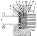
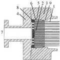
ガス分離膜モジュールの模式図を図5〜9に示す。図5が中空糸エレメントの模式図、図6が中空糸エレメントの管板付近の拡大図、図7が容器の模式図、図8が中空糸エレメントを容器内に収納した状態での模式図、図9が管板と容器の係合部分を示す断面概略図である。
中空糸エレメントの模式図を図5に示す。多数本のポリイミド製の中空糸膜1をループさせて中空糸膜の両端の開口が束の一方の端部で揃うように束ね、その端部を管板2が前記多数本の中空糸膜の開口を保持するようにして包埋して固着した。管板2の略中心部にねじを形成した樹脂製の芯管接続部15を包埋し、アルミ合金製の芯管14を芯管接続部15にねじ止めすることで中空糸束の略中心部に配置した。管板2はエポキシ樹脂製であって、直径は250mm、厚さは85mmとした。フィルム状物11によって、中空糸束の側面の面積の70%を覆った。そのフィルム状物11は、ステンレス製のキャップ12を介して芯管14に固定された。中空糸束の側面のうちフィルム状物11で覆われていない部分(管板2とフィルム状物11との間)を、網状物によって覆った。[Example 1]
The schematic diagram of a gas separation membrane module is shown in FIGS. FIG. 5 is a schematic diagram of a hollow fiber element, FIG. 6 is an enlarged view of the vicinity of a tube plate of the hollow fiber element, FIG. 7 is a schematic diagram of a container, and FIG. 8 is a schematic diagram in a state where the hollow fiber element is housed in the container. FIG. 9 is a schematic cross-sectional view showing an engagement portion between the tube plate and the container.
A schematic diagram of the hollow fiber element is shown in FIG. A large number of polyimide
図5に示した中空糸エレメントの管板付近の拡大図を図6に示す。管板の外周面には、ステンレス製の円筒状の補助部材13を設置した。補助部材には、ステンレス製の管板止め(多孔板)8、ステンレス製の移動止め9をボルトにより結合した。補助部材には、内面と外面に形成したOリング保持溝5に気密手段としてのOリング6を配置した。補助部材外面に配置されたOリングは、補助部材と容器との間の気密を保つ機能を有する。運転時には、多孔板で支持される管板が補助部材内面のOリングと接触するため、原料ガス室と透過ガス室との気密が保たれる。 FIG. 6 shows an enlarged view of the vicinity of the tube sheet of the hollow fiber element shown in FIG. A cylindrical
容器の模式図を図7に示す。鉄鋼製の容器3は、円筒状であり、中空糸エレメントを出し入れする開口17、芯管14を容器に固定し且つ芯管内のガス流路からのガスを容器外へ導く機能を備えた芯管固定部18、及び混合ガス導入口19を備える。 A schematic diagram of the container is shown in FIG. The
図5に示した中空糸エレメントを図7に示した容器内に収容した状態の模式図を図8に示す。中空糸エレメントは、中空糸エレメントを出し入れする開口17から容器内に挿入して収納され、中空糸エレメントの管板とは反対側の芯管14の端部を、芯管14の端部に形成されたOリング固定溝5に配置したOリングとともに芯管固定部18に接続し、中空糸エレメントの管板2は補助部材及び補助部材外壁のOリング固定溝に配置したOリングと共に容器内の開口17の所定位置に配置した。そして、中空糸エレメントが収納された容器の開口17には、管板2の外側に多孔板8を挿入し、更にその外側に透過ガス排出口7を備えた蓋4を配し、蓋4をボルトによって固定した。収納された状態での管板と容器内壁との係合を断面概略図として図9に示す。なお、この中空糸エレメントは、容器に脱着可能なものである。 FIG. 8 shows a schematic diagram of the state in which the hollow fiber element shown in FIG. 5 is accommodated in the container shown in FIG. The hollow fiber element is inserted into the container through the
運転時について説明する。混合ガス導入口19から導入された高圧の混合ガスは、原料ガス室を中空糸膜の表面に接しながら流れて、芯管14の孔16、ガス流路及び端部の孔を経由し、芯管固定部18を介して容器の外側の空間へ排出された。混合ガスが中空糸膜に接して流れる際、混合ガスの特定の成分ガスが中空糸膜を選択的に透過する。中空糸膜を選択的に透過した透過ガスは、中空糸膜内を流れて中空糸膜の開口から透過ガス室に集められ、蓋4に形成された透過ガス排出口7から排出された。 The operation will be described. The high-pressure mixed gas introduced from the mixed
前記ガス分離膜モジュールにおいて、管板が運転時とは逆向きに圧力を受ける場合を検討した。透過ガス排出口から徐々に圧力を上げながら圧縮空気を供給すると、0.2MPa(ゲージ圧)の圧力で安全機構が作動し、透過ガス室と原料ガス室との気密が破れ、透過ガス室から原料ガス室にガスがリークした。そのまま透過ガス排出口から供給する圧縮空気の圧力を上昇させても、ガスがリークするため透過ガス室と原料ガス室との圧力差が大きくならず、中空糸エレメントは破損しなかった。 In the gas separation membrane module, the case where the tube plate receives pressure in the direction opposite to that during operation was examined. When compressed air is supplied while gradually increasing the pressure from the permeate gas discharge port, the safety mechanism is activated at a pressure of 0.2 MPa (gauge pressure), the airtightness between the permeate gas chamber and the raw material gas chamber is broken, and from the permeate gas chamber Gas leaked into the source gas chamber. Even if the pressure of the compressed air supplied from the permeate gas discharge port was increased as it was, the gas leaked, so the pressure difference between the permeate gas chamber and the raw material gas chamber was not increased, and the hollow fiber element was not damaged.
〔比較例〕
比較例として、本発明の安全機構を有さず、図10の断面概略図で示すように管板を容器に固定した以外は実施例1と同様のガス分離膜モジュールにおいて、管板が運転時とは逆向きに圧力を受ける場合を検討した。
透過ガス排出口から3MPaの圧力で圧縮空気を供給したところ、管板が破損した。[Comparative Example]
As a comparative example, in the same gas separation membrane module as in Example 1, except that the safety mechanism of the present invention was not provided and the tube sheet was fixed to the container as shown in the schematic cross-sectional view of FIG. The case of receiving pressure in the opposite direction was studied.
When compressed air was supplied from the permeate gas outlet at a pressure of 3 MPa, the tube sheet was damaged.
本発明において、運転時とは逆向きに圧力を受けた際の中空糸エレメントの破損を回避することができる安全機構を容器内に備えたシェルフィード型ガス分離膜モジュールを提供することができる。本発明のシェルフィード型ガス分離膜モジュールの安全機構は、特別な部品を外付けする必要がなく、簡便な構造であって、特別なスペースを必要しない。その結果、中空糸膜の有効面積を減らす必要がないからガス分離能力を低下させることがない。
In the present invention, it is possible to provide a shell-feed type gas separation membrane module provided with a safety mechanism in a container capable of avoiding damage to the hollow fiber element when subjected to pressure in the direction opposite to that during operation. The safety mechanism of the shell feed type gas separation membrane module of the present invention does not require any special parts, and has a simple structure and does not require any special space. As a result, since it is not necessary to reduce the effective area of the hollow fiber membrane, the gas separation ability is not reduced.
1:中空糸膜
2:管板
3:容器
4:蓋
5:Oリング保持溝
6:気密手段(Oリング)
7:透過ガス排出口
8:管板止め(多孔板)
9:移動止め
10:容器内壁拡大部
11:フィルム状物
12:キャップ
13:補助部材
14:芯管
15:芯管接続部
16:芯管部穴
17:容器開口
18:芯管固定部
19:混合ガス導入口
20:蓋体
21:容器
21a:容器の段部
22:隔壁(管板)
22b、22d、22f、22h:環状部材
26:分離流体室(透過ガス室)
28:中空糸(中空糸膜)
30:隔壁の段部
32:環状部材の凸部
34:押え部材
34a:押え部材本体
34b:多孔質層
36:押え部材の孔
38:ボルト
40:シールリング(Oリング)1: hollow fiber membrane 2: tube sheet 3: container 4: lid 5: O-ring holding groove 6: airtight means (O-ring)
7: Permeate gas outlet 8: Tube plate stopper (perforated plate)
9: Detent 10: Container inner wall enlargement part 11: Film-like object 12: Cap 13: Auxiliary member 14: Core tube 15: Core tube connection part 16: Core pipe part hole 17: Container opening 18: Core pipe fixing part 19: Mixed gas inlet 20: Lid 21:
22b, 22d, 22f, 22h: annular member 26: separation fluid chamber (permeate gas chamber)
28: Hollow fiber (hollow fiber membrane)
30: Step part 32 of the partition wall: Convex part 34 of the annular member: Presser member 34a: Presser member body 34b: Porous layer 36:
Claims (6)
Translated fromJapanese(1)管板は、運転時に供給された混合ガスの圧力を受けると、管板止めで支持され、管板で間仕切られた容器内の二つの空間の気密が保たれる、
(2)管板は、運転時とは逆向きに圧力を受けると、前記逆向きの圧力で押されて容器内で移動し、管板で間仕切られた容器内の二つの空間の気密が失われる、
ように構成されたことを特徴とするシェルフィード型ガス分離膜モジュール。A hollow fiber element in which at least one end of a hollow fiber bundle made of a plurality of hollow fiber membranes is fixed and embedded by a tube plate is housed in a container, and a high-pressure mixed gas is contained in the hollow fiber in the container. A shell-feed type gas separation membrane module that performs gas separation by supplying to the outer space of the membrane,
(1) When the tube plate receives the pressure of the mixed gas supplied during operation, the tube plate is supported by the tube plate stopper, and the two spaces in the container partitioned by the tube plate are kept airtight.
(2) When the tube plate receives pressure in the opposite direction to that during operation, the tube plate is pushed by the reverse pressure and moves in the vessel, and the airtightness of the two spaces in the vessel partitioned by the tube plate is lost. Called
A shell feed type gas separation membrane module, characterized in that it is configured as described above.
Priority Applications (3)
| Application Number | Priority Date | Filing Date | Title |
|---|---|---|---|
| JP2007095574AJP5135854B2 (en) | 2007-03-30 | 2007-03-30 | Shell feed type gas separation membrane module |
| US12/521,745US8182592B2 (en) | 2006-12-29 | 2007-12-27 | Shell feed type gas separation membrane module |
| PCT/JP2007/075140WO2008081877A1 (en) | 2006-12-29 | 2007-12-27 | Shell feed type gas separation membrane module |
Applications Claiming Priority (1)
| Application Number | Priority Date | Filing Date | Title |
|---|---|---|---|
| JP2007095574AJP5135854B2 (en) | 2007-03-30 | 2007-03-30 | Shell feed type gas separation membrane module |
Publications (2)
| Publication Number | Publication Date |
|---|---|
| JP2008253869A JP2008253869A (en) | 2008-10-23 |
| JP5135854B2true JP5135854B2 (en) | 2013-02-06 |
Family
ID=39978018
Family Applications (1)
| Application Number | Title | Priority Date | Filing Date |
|---|---|---|---|
| JP2007095574AExpired - Fee RelatedJP5135854B2 (en) | 2006-12-29 | 2007-03-30 | Shell feed type gas separation membrane module |
Country Status (1)
| Country | Link |
|---|---|
| JP (1) | JP5135854B2 (en) |
Families Citing this family (1)
| Publication number | Priority date | Publication date | Assignee | Title |
|---|---|---|---|---|
| KR101721849B1 (en)* | 2016-06-24 | 2017-04-04 | 한국산업기술시험원 | Gas separation membrane module |
Family Cites Families (6)
| Publication number | Priority date | Publication date | Assignee | Title |
|---|---|---|---|---|
| JPS59154306U (en)* | 1983-03-31 | 1984-10-16 | 日東電工株式会社 | fluid separation device |
| US4675109A (en)* | 1985-05-08 | 1987-06-23 | E. I. Du Pont De Nemours And Company | Reverse osmosis permeator |
| JPS63224714A (en)* | 1987-03-13 | 1988-09-19 | Ube Ind Ltd | gas separation equipment |
| JP3236103B2 (en)* | 1993-02-05 | 2001-12-10 | ダイセル化学工業株式会社 | Hollow fiber membrane module |
| JP2003159517A (en)* | 2001-11-27 | 2003-06-03 | Ube Ind Ltd | Hollow fiber separation membrane module |
| JP2005218901A (en)* | 2004-02-03 | 2005-08-18 | Nitto Denko Corp | Separation membrane module and liquid separation apparatus using the same |
- 2007
- 2007-03-30JPJP2007095574Apatent/JP5135854B2/ennot_activeExpired - Fee Related
Also Published As
| Publication number | Publication date |
|---|---|
| JP2008253869A (en) | 2008-10-23 |
Similar Documents
| Publication | Publication Date | Title |
|---|---|---|
| US8182592B2 (en) | Shell feed type gas separation membrane module | |
| US9199191B2 (en) | Gas separation membrane module and method of replacing a hollow fiber element | |
| US7338601B2 (en) | Membrane separation assemblies | |
| EP1175253B1 (en) | Hollow-fiber membrane devices and methods of assembly | |
| WO2014024961A1 (en) | Gas-separating membrane module | |
| JP7201043B2 (en) | Separation membrane module | |
| WO2013084804A1 (en) | Support structure for cylindrical tube, and sealing method for cylindrical tube | |
| JP5135854B2 (en) | Shell feed type gas separation membrane module | |
| JP5742913B2 (en) | Shell feed type gas separation membrane module | |
| EP0288725A2 (en) | Apparatus and method for protecting gas separation membranes from damage due to a reversal of differential pressure | |
| JP6069891B2 (en) | Gas separation membrane module | |
| JP3972528B2 (en) | Fluid separation membrane module and separation method | |
| RU2771559C2 (en) | Device for filtering and separating liquid mixtures under pressure by means of membranes | |
| JP2003159517A (en) | Hollow fiber separation membrane module | |
| KR101902458B1 (en) | Hollowfiber Membrane Moldule | |
| US10744462B2 (en) | Separation membrane module | |
| US11654401B2 (en) | Gas separation membrane cartridge with clamshell retainer | |
| JP6051687B2 (en) | Gas separation membrane module | |
| KR20180099621A (en) | Gas Separation Membrane Module for Reactive Gas Service | |
| JP2017177071A (en) | Separation membrane module and hollow fiber membrane element | |
| JPH0739715A (en) | Gas separator | |
| WO2023162747A1 (en) | Separation membrane module, separation membrane module unit, and method for operating same | |
| JP2014061492A (en) | Hollow fiber element and gas separation membrane module having the same | |
| JP2003010648A (en) | Hollow fiber separation membrane module and gas separation method | |
| JP2001079359A (en) | Method for fixing membrane module and liquid processing apparatus |
Legal Events
| Date | Code | Title | Description |
|---|---|---|---|
| A621 | Written request for application examination | Free format text:JAPANESE INTERMEDIATE CODE: A621 Effective date:20091214 | |
| TRDD | Decision of grant or rejection written | ||
| A01 | Written decision to grant a patent or to grant a registration (utility model) | Free format text:JAPANESE INTERMEDIATE CODE: A01 Effective date:20121016 | |
| A01 | Written decision to grant a patent or to grant a registration (utility model) | Free format text:JAPANESE INTERMEDIATE CODE: A01 | |
| A61 | First payment of annual fees (during grant procedure) | Free format text:JAPANESE INTERMEDIATE CODE: A61 Effective date:20121029 | |
| R150 | Certificate of patent or registration of utility model | Free format text:JAPANESE INTERMEDIATE CODE: R150 | |
| FPAY | Renewal fee payment (event date is renewal date of database) | Free format text:PAYMENT UNTIL: 20151122 Year of fee payment:3 | |
| R250 | Receipt of annual fees | Free format text:JAPANESE INTERMEDIATE CODE: R250 | |
| R250 | Receipt of annual fees | Free format text:JAPANESE INTERMEDIATE CODE: R250 | |
| R250 | Receipt of annual fees | Free format text:JAPANESE INTERMEDIATE CODE: R250 | |
| LAPS | Cancellation because of no payment of annual fees |