JP5128058B2 - Multi-shot stroke surgical instrument including an electroactive polymer anti-backup mechanism - Google Patents
Multi-shot stroke surgical instrument including an electroactive polymer anti-backup mechanismDownload PDFInfo
- Publication number
- JP5128058B2 JP5128058B2JP2005217100AJP2005217100AJP5128058B2JP 5128058 B2JP5128058 B2JP 5128058B2JP 2005217100 AJP2005217100 AJP 2005217100AJP 2005217100 AJP2005217100 AJP 2005217100AJP 5128058 B2JP5128058 B2JP 5128058B2
- Authority
- JP
- Japan
- Prior art keywords
- firing
- backup
- handle
- actuator
- constant
- Prior art date
- Legal status (The legal status is an assumption and is not a legal conclusion. Google has not performed a legal analysis and makes no representation as to the accuracy of the status listed.)
- Expired - Fee Related
Links
- 229920001746electroactive polymerPolymers0.000titleclaimsdescription20
- 230000007246mechanismEffects0.000titleabstractdescription61
- 238000010304firingMethods0.000claimsabstractdescription166
- 230000033001locomotionEffects0.000claimsabstractdescription34
- 239000012636effectorSubstances0.000claimsabstractdescription27
- 239000000758substrateSubstances0.000claimsdescription33
- 230000004044responseEffects0.000claimsdescription6
- 238000000034methodMethods0.000abstractdescription14
- 229920000642polymerPolymers0.000abstractdescription9
- 230000000903blocking effectEffects0.000description17
- 230000006835compressionEffects0.000description17
- 238000007906compressionMethods0.000description17
- 239000000835fiberSubstances0.000description12
- 230000002093peripheral effectEffects0.000description10
- 210000001519tissueAnatomy0.000description8
- 230000008859changeEffects0.000description7
- 230000008878couplingEffects0.000description7
- 238000010168coupling processMethods0.000description7
- 238000005859coupling reactionMethods0.000description7
- 239000012530fluidSubstances0.000description7
- 229910000831SteelInorganic materials0.000description6
- 239000010959steelSubstances0.000description6
- 230000008901benefitEffects0.000description5
- 230000005540biological transmissionEffects0.000description4
- 239000000463materialSubstances0.000description4
- BASFCYQUMIYNBI-UHFFFAOYSA-NplatinumChemical compound[Pt]BASFCYQUMIYNBI-UHFFFAOYSA-N0.000description4
- 229920005594polymer fiberPolymers0.000description3
- 238000001356surgical procedureMethods0.000description3
- 238000004804windingMethods0.000description3
- 230000005355Hall effectEffects0.000description2
- 230000009471actionEffects0.000description2
- 239000002131composite materialSubstances0.000description2
- 229920001940conductive polymerPolymers0.000description2
- 239000004020conductorSubstances0.000description2
- 230000007812deficiencyEffects0.000description2
- 230000000694effectsEffects0.000description2
- 229910052697platinumInorganic materials0.000description2
- 230000002265preventionEffects0.000description2
- 241001631457CannulaSpecies0.000description1
- 210000001015abdomenAnatomy0.000description1
- 239000000853adhesiveSubstances0.000description1
- 230000001070adhesive effectEffects0.000description1
- 238000007664blowingMethods0.000description1
- 230000008602contractionEffects0.000description1
- 239000003814drugSubstances0.000description1
- 229940079593drugDrugs0.000description1
- 238000002651drug therapyMethods0.000description1
- 230000005684electric fieldEffects0.000description1
- 238000012976endoscopic surgical procedureMethods0.000description1
- 238000005516engineering processMethods0.000description1
- 239000004744fabricSubstances0.000description1
- 238000001415gene therapyMethods0.000description1
- 238000003780insertionMethods0.000description1
- 230000037431insertionEffects0.000description1
- 150000002500ionsChemical class0.000description1
- 238000012830laparoscopic surgical procedureMethods0.000description1
- 230000007257malfunctionEffects0.000description1
- 230000004048modificationEffects0.000description1
- 238000012986modificationMethods0.000description1
- 210000003205muscleAnatomy0.000description1
- 210000000056organAnatomy0.000description1
- 230000002980postoperative effectEffects0.000description1
- 230000008569processEffects0.000description1
- 230000002250progressing effectEffects0.000description1
- 238000011084recoveryMethods0.000description1
- 238000007789sealingMethods0.000description1
- 230000008961swellingEffects0.000description1
- 230000001225therapeutic effectEffects0.000description1
- 239000010409thin filmSubstances0.000description1
- 238000002604ultrasonographyMethods0.000description1
- 210000001835visceraAnatomy0.000description1
Images


Classifications
- A—HUMAN NECESSITIES
- A61—MEDICAL OR VETERINARY SCIENCE; HYGIENE
- A61B—DIAGNOSIS; SURGERY; IDENTIFICATION
- A61B17/00—Surgical instruments, devices or methods
- A61B17/068—Surgical staplers, e.g. containing multiple staples or clamps
- A61B17/072—Surgical staplers, e.g. containing multiple staples or clamps for applying a row of staples in a single action, e.g. the staples being applied simultaneously
- A61B17/07207—Surgical staplers, e.g. containing multiple staples or clamps for applying a row of staples in a single action, e.g. the staples being applied simultaneously the staples being applied sequentially
- A—HUMAN NECESSITIES
- A61—MEDICAL OR VETERINARY SCIENCE; HYGIENE
- A61B—DIAGNOSIS; SURGERY; IDENTIFICATION
- A61B17/00—Surgical instruments, devices or methods
- A61B17/068—Surgical staplers, e.g. containing multiple staples or clamps
- A—HUMAN NECESSITIES
- A61—MEDICAL OR VETERINARY SCIENCE; HYGIENE
- A61B—DIAGNOSIS; SURGERY; IDENTIFICATION
- A61B17/00—Surgical instruments, devices or methods
- A61B17/28—Surgical forceps
- A61B17/29—Forceps for use in minimally invasive surgery
- A61B17/2909—Handles
- A—HUMAN NECESSITIES
- A61—MEDICAL OR VETERINARY SCIENCE; HYGIENE
- A61B—DIAGNOSIS; SURGERY; IDENTIFICATION
- A61B17/00—Surgical instruments, devices or methods
- A61B2017/00367—Details of actuation of instruments, e.g. relations between pushing buttons, or the like, and activation of the tool, working tip, or the like
- A61B2017/00398—Details of actuation of instruments, e.g. relations between pushing buttons, or the like, and activation of the tool, working tip, or the like using powered actuators, e.g. stepper motors, solenoids
- A—HUMAN NECESSITIES
- A61—MEDICAL OR VETERINARY SCIENCE; HYGIENE
- A61B—DIAGNOSIS; SURGERY; IDENTIFICATION
- A61B17/00—Surgical instruments, devices or methods
- A61B2017/00367—Details of actuation of instruments, e.g. relations between pushing buttons, or the like, and activation of the tool, working tip, or the like
- A61B2017/00407—Ratchet means
- A—HUMAN NECESSITIES
- A61—MEDICAL OR VETERINARY SCIENCE; HYGIENE
- A61B—DIAGNOSIS; SURGERY; IDENTIFICATION
- A61B17/00—Surgical instruments, devices or methods
- A61B2017/00831—Material properties
- A61B2017/00867—Material properties shape memory effect
- A61B2017/00871—Material properties shape memory effect polymeric
Landscapes
- Health & Medical Sciences (AREA)
- Life Sciences & Earth Sciences (AREA)
- Surgery (AREA)
- Heart & Thoracic Surgery (AREA)
- Engineering & Computer Science (AREA)
- Biomedical Technology (AREA)
- Nuclear Medicine, Radiotherapy & Molecular Imaging (AREA)
- Medical Informatics (AREA)
- Molecular Biology (AREA)
- Animal Behavior & Ethology (AREA)
- General Health & Medical Sciences (AREA)
- Public Health (AREA)
- Veterinary Medicine (AREA)
- Surgical Instruments (AREA)
- Saccharide Compounds (AREA)
Abstract
Description
Translated fromJapanese本特許出願は2004年7月28日に出願されていて、シェルトンIV世(Shelton IV)に譲渡されている「サージカル・インストルメント・インコーポレイティング・アン・エレクトリカリー・アクチュエイテッド・アーティキュレーション・メカニズム(SURGICAL INSTRUMENT INCORPORATING AN ELECTRICALLY ACTUATED ARTICULATION MECHANISM)」を発明の名称とする米国仮特許出願第60/591,694号の恩典を主張している。 This patent application was filed on July 28, 2004 and is assigned to “Surgery Instrument Incorporating An Electrically Actuated Articulation Mechanism” assigned to Shelton IV. Claims the benefit of US Provisional Patent Application No. 60 / 591,694, whose title is "SURGICAL INSTRUMENT INCORPORATING AN ELECTRICALLY ACTUATED ARTICULATION MECHANISM".
本発明は一般に組織に数列のステープルを供給すると共にそれらのステープルの列の間の組織を切断することのできる外科ステープル器具に関連しており、特に、これらのステープル器具に関連する種々の改善および偶発的な発射を排除するこれらのステープル器具における種々の部品を形成するためのプロセスにおける種々の改善に関連している。 The present invention generally relates to surgical stapling instruments that are capable of supplying several rows of staples to tissue and cutting tissue between the rows of staples, and in particular, various improvements and associated with these stapling devices. Associated with various improvements in the process for forming the various parts in these stapling instruments that eliminate accidental firing.
内視鏡式および腹腔鏡式の外科器具はその比較的に小さな切開部分が術後の回復時間および合併症を減少する傾向が高いことにより従来の切開式の外科装置よりも好まれる場合が多い。すなわち、これらの内視鏡式および腹腔鏡式の外科処置は比較的に人気があり、これらの方法をさらに開発する刺激を与えている。例えば、腹腔鏡式の処置において、手術は一定の小さな切開部分を通して腹部の内部において行なわれる。同様に、内視鏡の処置において、手術は皮膚の小さな入口の創傷部分を通して挿入した細い内視鏡管により何らかの身体の中空の内臓の中において行なわれる。 Endoscopic and laparoscopic surgical instruments are often preferred over traditional open surgical devices due to their relatively small incision tending to reduce post-operative recovery time and complications . That is, these endoscopic and laparoscopic surgical procedures are relatively popular and provide a stimulus for further development of these methods. For example, in laparoscopic procedures, surgery is performed inside the abdomen through a small incision. Similarly, in endoscopic procedures, surgery is performed in the hollow internal organs of some body by means of a thin endoscopic tube inserted through a small entrance wound in the skin.
腹腔鏡式および内視鏡式の処置は一般にその手術領域にガスを吹き込むことを必要とする。従って、そのガスが切開部分を通して体内に流入または流出しないことを確実にするためにその体内に挿入するあらゆる器具を密封する必要がある。さらに、腹腔鏡式および内視鏡式の処置は外科医が切開部分から遠く外れている種々の器官、組織および/または脈管に作用することを必要とする場合が多い。従って、これらの処置において使用する器具は一般的に長く細いと共にその器具の基端部から機能的に制御可能である。 Laparoscopic and endoscopic procedures generally require blowing gas into the surgical area. Therefore, any instrument inserted into the body must be sealed to ensure that the gas does not enter or exit the body through the incision. Furthermore, laparoscopic and endoscopic procedures often require the surgeon to act on various organs, tissues and / or vessels that are far from the incision. Thus, the instruments used in these procedures are generally long and thin and functionally controllable from the proximal end of the instrument.
相当な開発が一定のトロカールのカニューレによる一定の所望の部位における先端部のエンド・エフェクターの正確な配置のために適している一定範囲の内視鏡式の外科器具において進んでいる。これらの先端部のエンド・エフェクターは一定の診断用または治療用の効果を達成するために多数の方法で組織に係合する(例えば、エンドカッター、グラスパー、カッター、ステープラー、クリップ・アプライヤー、アクセス装置、薬物/遺伝子療法配給装置、および超音波、RF、レーザー等を使用するエネルギー装置等)。 Considerable development is progressing in a range of endoscopic surgical instruments that are suitable for the precise placement of the tip end effector at a desired site with a trocar cannula. These tip end effectors engage the tissue in a number of ways to achieve a certain diagnostic or therapeutic effect (eg, end cutters, graspers, cutters, staplers, clip appliers, access Devices, drug / gene therapy delivery devices, and energy devices using ultrasound, RF, lasers, etc.).
既知の外科ステープラーは同時に組織に一定の長手方向の切開部分を作成してその切開部分のそれぞれの対向している側に数列のステープルを供給する一定のエンド・エフェクターを含む。さらに、このエンド・エフェクターは一対の協同作用するあご部材を含み、これらのあご部材は、この器具が内視鏡式または腹腔鏡式の用途に対応することを目的としている場合に、一定のカニューレの通路を通過することができる。これらのあご部材の内の1個は少なくとも2個の横方向に離間しているステープルの列を有する一定のステープル・カートリッジを受容している。また、別のあご部材は上記カートリッジの中のステープルの各列に対して整合しているステープル形成用のポケットを有している一定のアンビルを定めている。さらに、上記器具は複数の往復動式のくさびを含み、これらは先端側に駆動される場合に、上記ステープル・カートリッジの中のそれぞれの開口部を通過してそれぞれのステープルを上記アンビルに向けて発射するためにこれらのステープルを支持している各ドライバーに係合する。 Known surgical staplers simultaneously include an end effector that creates a longitudinal incision in tissue and supplies several rows of staples to each opposing side of the incision. In addition, the end effector includes a pair of cooperating jaw members that can be used with certain cannulas when the instrument is intended for endoscopic or laparoscopic applications. Can pass through. One of these jaw members receives a staple cartridge having at least two laterally spaced rows of staples. Another jaw member defines an anvil having staple forming pockets aligned with each row of staples in the cartridge. The instrument further includes a plurality of reciprocating wedges that, when driven distally, pass through respective openings in the staple cartridge to direct the respective staples toward the anvil. Engage with each driver supporting these staples for firing.
一般に、単一の閉鎖ストロークの後に単一の発射ストロークを行なうことが切断処理をしてステープル処理を行なうための好都合で効率的な方法である。しかしながら、一部の場合において、多数回の発射ストロークが望まれることがある。例えば、外科医は一定の範囲のあご部材の寸法による切断の所望の長さに対応する一定の長さのステープル・カートリッジを選択する。この場合に、ステープル・カートリッジが長くなるほど発射ストロークが長くなる。従って、その発射を行なうために、一定の比較的に短いステープル・カートリッジに比べて多数の組織を切断して多数のステープルを駆動するために上記のような比較的に長いステープル・カートリッジに対応する一定の比較的に大きな力を生じるために一定の手絞り型のトリガーが必要とされる。従って、その力の量が一部の外科医の手の強度を超えないように、比較的に少量で比較的に短いカートリッジに匹敵することが望ましいと考えられる。加えて、上記のような比較的に大形のステープル・カートリッジになじまない一部の外科医は一定の予想外に大きな力が必要とされる場合に食い込みやその他の機能不全が生じることを問題にする可能性がある。 In general, a single firing stroke followed by a single firing stroke is a convenient and efficient method for cutting and stapling. However, in some cases, multiple firing strokes may be desired. For example, the surgeon selects a length of staple cartridge that corresponds to the desired length of cut with a range of jaw member dimensions. In this case, the longer the staple cartridge, the longer the firing stroke. Thus, to perform its firing, it accommodates a relatively long staple cartridge as described above to drive a large number of staples by cutting a large number of tissues compared to a certain relatively short staple cartridge. A constant hand drawn trigger is required to generate a certain relatively large force. Therefore, it may be desirable to compare a relatively short cartridge with a relatively short cartridge so that the amount of force does not exceed the strength of some surgeon's hands. In addition, some surgeons who are not familiar with the relatively large staple cartridges mentioned above have problems with biting and other malfunctions when certain unexpectedly high forces are required. there's a possibility that.
開示内容の全体において本明細書において参考文献として含まれる2003年9月29日に出願されているシェルトン(Shelton)他に譲渡されている「サージカル・ステープリング・インストルメント・ウィズ・マルチストローク・ファイアリング・インコーポレイティング・アン・アンチ−バックアップ・メカニズム(SURGICAL STAPLING INSTRUMENT WITH MULTISTROKE FIRING INCORPORATING AN ANTI-BACKUP MECHANISM)」を発明の名称とする同時係属で共有の米国特許出願公開第2005/0067457A1号、すなわち、米国特許出願第10/673,929号において、一定の有利な抗バックアップ機構が、一定の発射部材が各発射ストローク中に先端側に移動する時に機械的に分離して、その発射トリガーが各発射ストロークの間に解除されている時に係合することにより、偶発的な後退を防止している。この場合に、完全な発射の移動時に、上記の抗バックアップ機構を分離する一定の機械的な結合がはずれて、一定の後退用のばねが発射部材を後退させることを可能にする。これにより、多数回の発射ストロークの利点が自動的な後退動作との組み合わせにおいて実現されている。 “Surgical Stapling Instrument with Multi-Stroke Fire” assigned to Shelton et al. Filed on Sep. 29, 2003, which is incorporated herein by reference in its entirety. US Patent Application Publication No. 2005 / 0067457A1, co-pending and co-pending US Patent Application Publication No. 2005 / 0067457A1, whose title is “SURGICAL STAPLING INSTRUMENT WITH MULTISTROKE FIRING INCORPORATING AN ANTI-BACKUP MECHANISM”, In US patent application Ser. No. 10 / 673,929, an advantageous anti-backup mechanism is mechanically separated when a firing member moves distally during each firing stroke, and its firing trigger is associated with each firing. Engage when released during a stroke And by, so as to prevent inadvertent retraction. In this case, during a full firing movement, the mechanical coupling separating the anti-backup mechanism is disengaged, allowing a retracting spring to retract the firing member. Thereby, the advantages of multiple firing strokes are realized in combination with automatic reverse movement.
さらに最近において、一定の類似している抗バックアップ機構がシェルトン(Shelton)他に譲渡されている「サージカル・ステープリング・インストルメント・インコーポレイティング・ア・マルチ−ストローク・ファイアリング・メカニズム・ウィズ・リターン・スプリング・ロータリー・マニュアル・レトラクション・システム(SURGICAL STAPLING INSTRUMENT INCORPORATING MULTI-STROKE FIRING MECHANISM WITH RETURN SPRING ROTARY MANUAL RETRACTION SYSTEM)」を発明の名称とする米国特許出願第11/052,387号およびスウェイズ(Swayze)他に譲渡されている「サージカル・ステープリング・インストルメント・インコーポレイティング・ア・ファイアリング・メカニズム・ハビング・ア・リンクド・ラック・トランスミッション(SURGICAL STAPLING INSTRUMENT INCORPORATING A FIRING MECHANISM HAVING A LINKED RACK TRANSMISSION)」を発明の名称とする米国特許出願第11/052,632号において開示されており、これら両方の開示はその内容全体が本明細書において参考文献として含まれる。 More recently, certain similar anti-backup mechanisms have been transferred to Shelton et al. “Surgical Stapling Instrument Incorporating A Multi-Stroke Firing Mechanism With Return. US Patent Application No. 11 / 052,387 and Swayze with the title “SURGICAL STAPLING INSTRUMENT INCORPORATING MULTI-STROKE FIRING MECHANISM WITH RETURN SPRING ROTARY MANUAL RETRACTION SYSTEM” ) "Surgical Stapling Instrument INCORPORATING A, Surgical Stapling Instrument Incorporating a Fireing Mechanism" FIRING MECHANISM HAVING A LINKED RACK TRANSMISSION) is disclosed in US patent application Ser. No. 11 / 052,632, both of which are incorporated herein by reference in their entirety.
上記の機械制御型の抗バックアップ機構は相当な臨床における有用性を提供しているが、さらに付加的な機能性を可能にする偶発的な後退を防止するための別の方法を提供することが望ましいと考えられる。
従って、各ストロークの間の偶発的な発射動作の後退の信頼性の高い変更可能な防止を伴う増大した発射動作の移動および/または減少した発射のための力に対応して多数回の発射を行なう一定の改善された外科ステープルおよび切断用の器具に対して相当な要望が存在している。 Thus, multiple firings in response to increased firing motion movement and / or reduced firing force with reliable changeable prevention of accidental firing motion retraction during each stroke. There is a considerable need for certain improved surgical stapling and cutting instruments to perform.
本発明は外科医により必要とされる過度の手の力を伴わずに一定の長いエンド・エフェクターを作動する一定の多数回発射ストローク式のハンドルを好都合に含む一定の外科ステープルおよび切断用の器具を提供することにより従来技術における上記およびその他の欠陥を解消している。この場合に、各発射部品の後退のバイアス力が完全な発射の移動後の一定の発射機構の後退を補助する。さらに、有利なことに、一定の電気的なアクチュエータが各発射ストロークの間における各発射部品の偶発的な後退を防止することを補助する。 The present invention provides a surgical stapling and cutting instrument that advantageously includes a multi-firing stroke handle that operates a long end effector without the excessive hand force required by the surgeon. By providing, the above and other deficiencies in the prior art are eliminated. In this case, the retraction bias force of each firing component assists the retraction of a constant firing mechanism after a full firing movement. In addition, advantageously, certain electrical actuators help prevent accidental retraction of each firing component during each firing stroke.
本発明の上記およびその他の目的および利点が以下の添付図面およびそれらの説明により明らかになる。 The above and other objects and advantages of the present invention will become apparent from the following accompanying drawings and description thereof.
従って、本発明によれば、各ストロークの間の偶発的な発射動作の後退の信頼性の高い変更可能な防止を伴う増大した発射動作の移動および/または減少した発射のための力に対応して多数回の発射を行なう一定の改善された外科ステープルおよび切断用の器具が提供できる。 Thus, the present invention accommodates increased firing movement movement and / or reduced firing force with reliable changeable prevention of accidental firing movement retraction during each stroke. An improved surgical stapling and cutting instrument with multiple firings can be provided.
本明細書に含まれていてその一部を構成している以下の添付図面は本発明の幾つかの実施例を示しており、上記本発明の概略的な説明、および以下のそれぞれの実施形態の詳細な説明と共に、本発明の原理を説明するために役立っている。 The following accompanying drawings, which are incorporated in and constitute a part of this specification, illustrate several embodiments of the present invention, and provide a schematic description of the invention described above and each of the following embodiments: Together with a detailed description of the present invention serves to explain the principles of the present invention.
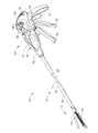
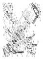
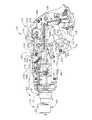
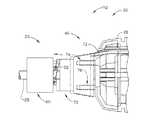
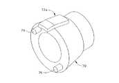
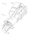
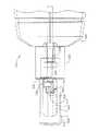
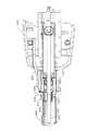
図1において、内視鏡式および腹腔鏡式の使用のために適している一定の外科装置が示されており、この装置は一定の多数回発射ストローク式機構、それぞれの発射部品の自動後退機構、および各発射ストロークの間における偶発的な後退を防止するための本発明に一貫している一定の好都合に電気的に作動する抗バックアップ機構を有利に組み合わせている。また、図2、3および3Aにおいて、図1における抗バックアップ機構の一例の態様が示されている。特に、一定の電気−機械式の(混成型の)抗バックアップ機構が上記の米国特許出願第11/052,387号および同第11/052,632号において詳細に記載されている完全に機械的な実施例を改良しており、これらの文献は共に本明細書におけるこの例示的な態様に共通するハンドルの閉鎖および発射の各動作をさらに完全に説明している。また、図4乃至図6において、電気作動型の抗バックアップ機構の一例の態様は図2,3および3Aにおいて示されている実施例に類似する放出のための一定の電気活性ポリマー(EAP)作動型の抗バックアップ・カム・チューブにより阻止される後退を防止するために一定のばね付勢型の係止プレートのみに依存している一定の抗バックアップ機構の機械的な発射の移動端部および手動の放出機構に対応する機械的な部分をさらに省いている。さらに、図7乃至図11において、上記の電気作動型の抗バックアップ機構の一例の態様は放出するために一定のEAP型アクチュエータにより緩められている発射機構を結合するために密接に巻かれている一定のコイルを採用している。また、図12乃至図15において、上記の電気作動型の抗バックアップ機構の一例の態様は係止するために拡張し、一定の周囲の外殻部分により内側に押し出されて発射ロッドに対して結合して接触しながら、解除するために収縮する一定のEAP分割型円筒形スリーブを採用している。一方、図16および図17においては、上記の電気作動型の抗バックアップ機構の一例の態様が収縮して発射ロッドに対して内側に結合して接触し、解除するために拡張する一定のEAP型の円筒形スリーブを採用している。 In FIG. 1, a surgical device is shown that is suitable for endoscopic and laparoscopic use, which includes a constant multi-stroke mechanism, an automatic retraction mechanism for each firing component. , And certain advantageously electrically operated anti-backup mechanisms consistent with the present invention to prevent accidental retraction during each firing stroke. 2, 3 and 3A show an example of the anti-backup mechanism in FIG. In particular, certain electro-mechanical (mixed) anti-backup mechanisms are fully mechanically described in detail in the above-mentioned US patent application Ser. Nos. 11 / 052,387 and 11 / 052,632. Both of these references have more fully described the handle closure and firing operations common to this exemplary embodiment herein. Also in FIGS. 4-6, an example embodiment of an electro-actuated anti-backup mechanism is a constant electro-active polymer (EAP) actuation for release similar to the embodiment shown in FIGS. 2, 3 and 3A. Mechanical firing moving end and manual of constant anti-backup mechanism relying only on constant spring-biased locking plate to prevent retraction blocked by mold anti-backup cam tube The mechanical part corresponding to the release mechanism is further omitted. Further, in FIGS. 7-11, an example embodiment of the above-described electrically actuated anti-backup mechanism is closely wound to couple a firing mechanism that is loosened by a certain EAP actuator to release. A constant coil is used. Also in FIGS. 12-15, an example embodiment of the above-described electrically actuated anti-backup mechanism expands to lock and is pushed inward by a surrounding shell portion and coupled to the firing rod A constant EAP split cylindrical sleeve that contracts to release while in contact is employed. On the other hand, in FIGS. 16 and 17, an embodiment of the above-described electrically actuated anti-backup mechanism is contracted to be in contact with the firing rod inwardly contacting and expanding to release The cylindrical sleeve is adopted.
各図面において、同一の参照番号または符号は幾つかの図面を通して同一の構成部品を示しており、図1において、一定の外科ステープルおよび切断用の器具10は一定のエンド・エフェクターの多数回ストローク式の発射機構を含み、この機構はこの例示的な態様において一定のステープル供給装置12である。一定のアンビル14が一定の細長い(ステープル)チャネル16に対するその旋回式の取付部分の回りに繰り返し可能に開閉できる。このステープル供給組立体12は細長い軸部18に対して基端側に取り付けられており、この軸部18はさらに一定のハンドル20に対して基端側に取り付けられている。特に、細長い軸部18の一定のフレーム基板21はその基端部においてハンドル20に回転可能に係合しており、その先端部においてステープル・チャネル16に取り付けられている。さらに、上記の軸部18およびステープル供給装置12は一体になって一定の実行部分22を形成している。このステープル供給組立体12はフレーム基板21を囲む一定の閉鎖チューブ24を先端側に進行させることにより閉鎖される。このような実行部分22における閉鎖状態のステープル供給組立体12はハンドル20を外部から操作することにより一定のトロカールのカニューレ(図示されていない)の中に挿入することに適している一定の小さな断面積を与えている。この実行部分22を位置決めした後に、ステープル供給組立体12は閉じられて組織に対してクランプされる。その後、一定の発射ロッド25として示されている一定の発射部材がフレーム基板21の中を先端側に進行してステープル供給組立体12の中において切断およびステープル処理を行なう。 In each of the drawings, the same reference numerals or symbols indicate the same components throughout the several views, and in FIG. 1, a surgical stapling and cutting
上記ハンドル20は、実行部分22を軸部18の長手軸の回りに回転させる一定の回転ノブ27等のような、ハンドル・ハウジング26に取り付けられている種々のユーザー制御手段を有している。また、ハンドル・ハウジング27に対する一定の取付位置の回りにピストル・グリップ30の前方において旋回する一定の閉鎖トリガー28を押すことにより、閉鎖チューブ24が先端側に移動してステープル供給組立体12が閉鎖する。さらに、この閉鎖トリガー28の前方において旋回する多数回ストローク式の発射トリガー32は発射ロッド25を先端側に進行させることにより、ステープル供給組立体12にその中にクランプされている組織を同時に切断およびステープル処理させる。外科医の手による1回のストローク当たりに必要とされる力の量を減少するために多数回の発射ストロークが採用されているので、左右のインジケータ・ホイール34,36(後者が図2において示されている)が回転してその発射の進行の指示手段を与えている。例えば、完全な発射の移動が3回の完全な発射のストロークを必要とし、上記のインジケータ・ホイール34,36が各ストローク当たりに1回転の1/3まで回転する場合があり得る。必要であれば、一定の手動後退レバー38が一定の電気−機械式の混成型抗バックアップ機構40を手動により分離することにより完全な発射の移動の前に後退を可能にし、さらに、結合または一定の後退のバイアス力における不足が存在する場合に後退のための補助を行なうことができる。また、閉鎖解除ボタン41が閉鎖トリガー28のクランプ時に外側に存在しており、部分的な発射が生じないようになっており、このことは閉鎖トリガー28のクランプ状態の解除を阻止する。 The
ハンドル20における後退のバイアス力が発射後の発射ロッド25を後退させる。一方、発射トリガーが別のストロークのために放出されると、抗バックアップ機構40が偶発的な後退を阻止するために発射ロッド25に係合する。好都合なことに、一定の抗バックアップ用の電気的なアクチュエータ42が一定の係止状態と係止解除状態との間において選択的に移動するために発射ロッド25の近くに位置決めされている。一定のコントロール・モジュール44が抗バックアップ用の電気的なアクチュエータ42を活性化する。すなわち、電力が外部の電源または一定の電力ボタン48を介してコントロール・モジュール44に接続している図示の電池46等により供給可能であり、この電力ボタン48は活性化時に照明される。上記コントロール・モジュール44は一定の発射解除センサー50により示されているように発射の係止および係止解除の時を決定するために上記外科切断およびステープル用の器具10の動作をモニターし、発射放出センサー50は発射トリガー32の上側の部分において一定の磁気標的52として仮想線で示されており、この標的52はハンドル・ハウジング26の内側に取り付けられている一定のホール効果型のトランスデューサ54に対して移動する。なお、上記発射ロッド25の係止または解除を保証する状況を感知するために別のセンサーが使用可能であることを認識する必要がある。 A reverse bias force on the
図1の抗バックアップ機構40の一例の態様が図2および図3において示されており、この態様は一定の貫通穴58を伴う一定の抗バックアップ・プレート56(図2)を含み、このプレート56は発射ロッド25を囲っていて係止プレート58よりも先端側に位置決めされている一定の弾性部材60により補助されて、当該発射ロッド25が先端側に進行する時に一定の横方向の無結合状態(「係止解除状態」)の位置まで前方に移動し、発射ロッド25が後退する時に一定の角度を付けた結合状態(「係止状態」)の位置まで後方に移動する。一定の下方タブ取付部材62(図2)がフレーム基板21の基端部における一定の下方リップ部分64から基端側に延在していて、抗バックアップ用の係止プレート56の下方のエッジ部分における一定の孔66の中を貫通している。この下方タブ取付部材62は抗バックアップ用の係止プレート56の下方部分をフレーム基板21よりも基端側に引っ張り、発射ロッド25が先端側に進行する時にその抗バックアップ用の係止プレート56を垂直にし、発射ロッド25が後退する時に後方に移動して一定の結合状態になることを可能にする。 An example embodiment of the
抗バックアップ用の弾性的な付勢部材68が発射ロッド25を囲っていて、係止プレート56の先端側に位置決めされている。この付勢部材68と係止プレート56との間の係合は係止プレート56の上部が逆方向に係止するように押し出すために両方の上部のエッジ部分の間に接合が生じる程度に制限されている。さらに、上記付勢部材68の先端側がフレーム基板21に接合していて、基端側にのみ拡張することを可能にしている。また、係止プレート56の基端側において、一定の抗バックアップ用のカム・チューブ70が発射ロッド25を囲っていて、長手方向に移動するように拘束されている。特に、一定の基端側に配向している抗バックアップ用のカム・ヨーク72は抗バックアップ用のカム・チューブ70の上部の基端側の表面に取り付けられて、ハンドル・ハウジング26の中に摺動自在に受容されていて、回転動作を拘束すると共にこの態様において一定の機械的な解除アクチュエータとして作用している。また、上記の抗バックアップ・カム・チューブ70はそれ自体で抗バックアップ・カム・ヨーク72により先端側に進行できるが、EAP型の円筒形のアクチュエータ74,76として示されている一対の電気的なアクチュエータにより進行できることが好都合である。なお、これらの抗バックアップ・カム・チューブ70およびEAP型の円筒形のアクチュエータ74,76は図4乃至図6における抗バックアップ機構40の一例の態様に共通しており、この場合に、一定の短小化したカム・ヨーク72aが抗バックアップ・カム・チューブ70を案内するためにのみ作用しており、解除のための機械的な作動のために連結していない。図3Aにおいて、幾つかの形態の内の一つを選択することにより係止プレート56の受動的および/または能動的な付勢(バイアス力の付加)を組み込むことができることが考慮されている。この場合に、上記の抗バックアップ・カム・ヨーク72が手動による使用者の入力による機械的な解除動作を伝達するために作用するか、発射の移動の自動的な端部が備えられている。 An anti-backup elastic biasing
図4の態様は弾性部材60が発射ロッド25aの一定の細い部分80を把持していてこれにより先端側に拘束されている一定の細い先端側のコイル78を有する一定の抗バックアップ用の圧縮ばね60aを含む点において異なっている。この抗バックアップ用の圧縮ばね60aはまた抗バックアップ用の係止プレート56に接触するように寸法付けられている一定の広げられた基端側のコイル部分82も有している。この結果、この抗バックアップ用の圧縮ばね60aは発射ロッド25aまたは抗バックアップ・カム・チューブ72aにより解消される全時間の係止用のバイアス力を供給する。 The embodiment of FIG. 4 is a constant anti-backup compression spring having a thin
図3Aにおいて、EAP型のアクチュエータ74,76はそれぞれゆるい収縮した形状を有しており、この形状は弾性部材60を抗バックアップ用の係止プレート56に対して基端側に押し当てて抗バックアップ・カム・チューブ70をハンドル・ハウジング26に対して基端側に押し出すことを可能にする。これらのEAP型のアクチュエータ74,76がエネルギー供給されると、これらのEAP型アクチュエータ74,76は仮想線で示されているように長手方向に拡張して、同様に仮想線で示されている抗バックアップ・カム・チューブ70を先端側に進行させる。なお、図2,3および3Aの態様が一定のゆるい収縮した状態および一定の活性化した拡張した状態を有する一定のEAP型のアクチュエータ(例えば、電気的に刺激される時に長手方向に拡張するように構成されている一定の貫通穴を伴う円筒形の積層状のEAPラミネート体等)により形成されている弾性部材60を伴って構成できることも考慮されている。これにより、係止用のバイアス力が発射のための力を減少するために選択的に除去可能になる。さらに、上記発射トリガー32は弾性部材60に対して係止プレート56を移動するために比較的に少ない力を必要とする。あるいは、弾性部材60は一定のゆるい収縮した状態および一定の活性化した拡張状態を有することができる。さらに、この弾性部材60はEAP繊維のアクチュエータの中に長手方向に包まれている一定の組み合わせ式の圧縮ばねとすることができ、あるいは一定のEAPの積層化したラミネート体のアクチュエータにより補助および/または拘束することも可能である。 In FIG. 3A, each of the
上記の電気活性ポリマー(EAP)は一組の導電体をドーピングしたポリマーであり、電圧が加えられるとその形状を変える。本質的に、この導電性のポリマーは特定の形態のイオン性の流体またはゲルおよび電極に対して組み合わされている。この場合に、この導電性のポリマーの中または外への流体/ゲルからのイオンの流れは加えられる電位により誘発され、この流れがそのポリマーの形状の変化を生じる。この電位は使用するポリマーおよびイオン性の流体に応じて1V乃至4Vの範囲内である。これらのEAPの一部は電圧が加えられる時に収縮し、他の一部は拡張する。また、これらのEAPは電圧を加える時に生じる効果を変えるためにばねまたは柔軟なプレート等のような種々の機械的な手段と組み合わせることも可能である。 The electroactive polymer (EAP) is a polymer doped with a set of conductors that changes shape when a voltage is applied. In essence, this conductive polymer is combined for a particular form of ionic fluid or gel and electrode. In this case, the flow of ions from the fluid / gel into or out of the conductive polymer is induced by an applied potential, which causes a change in the shape of the polymer. This potential is in the range of 1V to 4V depending on the polymer used and the ionic fluid. Some of these EAPs contract when voltage is applied, and others expand. These EAPs can also be combined with various mechanical means such as springs or flexible plates to change the effects that occur when applying a voltage.
上記EAPは2個の基本的な型があり、それぞれの型に多数の形態がある。これら2種類の基本的な型は一定の繊維の束および一定の積層体の態様である。さらに、この繊維の束は約30ミクロン乃至50ミクロンの繊維により構成されている。また、これらの繊維は種々の織物と同様に一定の束に織ることができ、このことによりEAP織り糸と呼ばれる場合が多い。この種のEAPは電圧が加えられると収縮する。さらに、電極は通常において一定の中央のワイヤ・コアと一定の導電性の外側シースであり、このシースはまた上記繊維の束の周囲のイオン性の流体を収容するために作用する。一定の市場において入手可能な繊維のEAP材料の一例がサンタ・フェ・サイエンス・アンド・テクノロジー社(Santa Fe Science and Technology)により製造されていて、パニオン(PANION)繊維として販売されており、米国特許第6,667,825号において記載されており、この文献はその内容全体において本明細書において参考文献として含まれる。 The EAP has two basic types, and each type has many forms. These two basic types are constant fiber bundles and constant laminate embodiments. Further, the fiber bundle is composed of fibers of about 30 to 50 microns. Also, these fibers can be woven into a fixed bundle, similar to various fabrics, and are often referred to as EAP yarns. This type of EAP contracts when a voltage is applied. In addition, the electrode is usually a central wire core and a conductive outer sheath, which also serves to contain the ionic fluid around the fiber bundle. An example of a fiber EAP material available in certain markets is manufactured by Santa Fe Science and Technology and sold as PANION fiber, US patent No. 6,667,825, which is hereby incorporated by reference in its entirety.
別の種類は一定の積層構造である。この構造はEAPポリマーの一定の層、イオン性ゲルの一定の層およびこの積層体のいずれかの面に取り付けられている2個の柔軟なプレートにより構成されている。一定の電圧が加えられると、上記正方形の積層体のプレートが一方向に拡張してその垂直の方向に収縮する。一定の市場において入手可能な積層体(プレート)のEAP材料の一例がSRIラボラトリーズ社(SRI Laboratories)の一事業部であるアーティフィシャル・マッスル社(Artificial Muscle)から入手可能である。プレート状のEAP材料はまた日本国のエアメックス社(EAMEX)からも入手可能であり、薄膜EAPとして呼ばれている。 Another type is a layered structure. This structure consists of a layer of EAP polymer, a layer of ionic gel, and two flexible plates attached to either side of the laminate. When a certain voltage is applied, the square laminate plate expands in one direction and contracts in the vertical direction. An example of a laminate (plate) EAP material available in certain markets is available from Artificial Muscle, a division of SRI Laboratories. Plate-like EAP material is also available from Airmex Corporation (EAMEX) of Japan and is referred to as thin film EAP.
上記EAPはエネルギー供給される時に容積を変化せず、これらは単に一方向に拡張または収縮してこれを横切る方向に逆のことを行なうことに注目する必要がある。この積層体の態様は一定の剛性の構造に当接している一方の側を含み、別の側を一定のピストンのように使用することによりその基本的な形態において使用できる。また、この材料を一定の柔軟なプレートのいずれかの面に接着することも可能である。この場合に、この柔軟なプレートのEAPの一方の面がエネルギー供給されると、このEAPが拡張して、そのプレートを逆の方向に曲げる。このことにより、そのプレートはそのエネルギー供給される面に応じていずれの方向にも曲げることが可能になる。 It should be noted that the EAPs do not change volume when energized, they simply expand or contract in one direction and do the opposite in the direction across it. This laminate embodiment can be used in its basic form by including one side abutting a structure of constant stiffness and using the other side like a piston. It is also possible to adhere this material to either side of a flexible plate. In this case, when one side of the EAP of the flexible plate is energized, the EAP expands and bends the plate in the opposite direction. This allows the plate to bend in either direction depending on the surface to which energy is supplied.
一定のEAP型アクチュエータは通常において協同して作用する多数個の層または一体に束ねられた繊維により構成されている。さらに、このEAPの機械的な構成はそのEAPアクチュエータおよびその動作能力を決定する。また、このEAPは長いストランドの状態で形成して単一の中央の電極の周囲に巻きつけることができる。さらに、一定の柔軟な外部の外側スリーブがそのアクチュエータの別の電極を形成すると共にこの装置の機能において必要なイオン性の流体を収容する。このような構成において、一定の電場がこれらの電極に加えられると、これらのEAPのストランドは短縮する。このEAP型アクチュエータの構成は一定の繊維EAP型アクチュエータとして呼ばれている。同様に、上記積層体の構成は一定の柔軟なプレートのいずれかの面における多数個の層の形態で配置することができ、あるいは単にその能力を高めるためにそれ自体の上に層状に配置することも可能である。一般的な繊維の構造は2%乃至4%の一定の有効ひずみを有しており、この場合に、典型的な積層体の態様はさらに高い電圧を利用して20%乃至30%を達成する。しかしながら、これらの性能の範囲は確定的でないことを認識する必要がある。 Certain EAP-type actuators are usually composed of multiple layers or fibers bundled together that work together. Furthermore, the mechanical configuration of this EAP determines its EAP actuator and its operating capability. The EAP can also be formed in a long strand and wrapped around a single central electrode. In addition, a flexible outer outer sleeve forms another electrode of the actuator and contains the ionic fluid required for the function of the device. In such a configuration, when a constant electric field is applied to these electrodes, these EAP strands shorten. The configuration of this EAP actuator is called a constant fiber EAP actuator. Similarly, the laminate configuration can be arranged in the form of multiple layers on either side of a flexible plate, or simply layered on itself to increase its capacity. It is also possible. Typical fiber structures have a constant effective strain of 2% to 4%, in which case the typical laminate embodiment achieves 20% to 30% using higher voltages. . However, it should be recognized that these performance ranges are not deterministic.
例えば、一定の積層体のEAP複合物は一定の正のプレート電極の層を一定のEAP層に取り付けて、このEAPの層をさらに一定のイオン性のセルの層に取り付け、さらにイオン性のセルの層を一定の負のプレート電極の層に取り付けることより形成できる。さらに、複数の積層体のEAP複合物をこれらの間に接着剤の各層を置くことにより一山に固定して一定のEAP型のプレート・アクチュエータを形成できる。なお、いずれかの方向に選択的に曲がることのできる逆のEAP型のアクチュエータも形成可能であることを認識する必要がある。 For example, a stack of EAP composites can have a layer of positive plate electrodes attached to a layer of EAP, this layer of EAP can be further attached to a layer of ionic cells, Can be formed by attaching the layer to a negative plate electrode layer. In addition, a plurality of laminate EAP composites can be secured in a stack by placing each layer of adhesive between them to form a fixed EAP type plate actuator. It should be recognized that an inverted EAP actuator that can be selectively bent in either direction can also be formed.
一定の収縮性のEAP繊維型アクチュエータは一定の長手方向のプラチナ・カソード・ワイヤを含むことができ、このカソード・ワイヤは一定の絶縁性のポリマーの基端側のキャップの中を通り、一定の正のアノードとして作用するために導電体がドーピングされている一定のプラスチック・シリンダーの中に形成されている一定の細長い円筒形のキャビティの中に延在している。また、このプラチナ・カソード・ワイヤの先端部は一定の絶縁性のポリマーの先端側のキャップの中に埋め込まれている。さらに、複数の収縮性のポリマー繊維が上記カソード・ワイヤに平行に配列されていてこれを囲っており、それぞれの端部がそれぞれの端部のキャップの中に埋め込まれている。また、上記のプラスチック・シリンダーの壁部が収縮性のポリマー繊維とカソード・ワイヤとの間の空間を充たすイオン性の流体またはゲルの中に密封するために上記円筒形のキャビティを封入するためにそれぞれの端部のキャップの周囲に取り付けられている。この結果、一定の電圧がこのプラスチック・シリンダーの壁部(アノード)とカソード・ワイヤとの間に加えられると、イオン性の流体が収縮しているポリマー繊維の中に入り、それぞれの外径を追随する長さの収縮を伴って膨潤させることにより、各端部のキャップを互いに引き寄せる。 A shrinkable EAP fiber actuator can include a longitudinal platinum cathode wire that passes through a proximal cap of a dielectric polymer and is constant. It extends into an elongated cylindrical cavity formed in a plastic cylinder doped with a conductor to act as a positive anode. The tip of the platinum cathode wire is embedded in a cap on the tip side of a certain insulating polymer. Further, a plurality of shrinkable polymer fibers are arranged parallel to and surround the cathode wire, each end being embedded in a cap at each end. The plastic cylinder wall also encloses the cylindrical cavity for sealing in an ionic fluid or gel that fills the space between the shrinkable polymer fiber and the cathode wire. Attached around the cap at each end. As a result, when a constant voltage is applied between the plastic cylinder wall (anode) and the cathode wire, the ionic fluid enters the shrinking polymer fibers and reduces the respective outer diameter. The caps at each end are pulled together by swelling with the following length of contraction.
図2および図3において、上記の米国特許出願第11/052,387号および同第11/052,632号に共通しているハンドル20の各構成部品は抗バックアップ・カム・チューブ72の閉鎖および発射および機械的な作動を行なう。このフレーム基板はハンドル20に回転可能に係合していて、回転ノブ27をねじることにより、実行部分22が回転するようになっている。この回転ノブ27のそれぞれの半分の外殻部分は一定の内側の突出部分90(図2)を含み、この突出部分90は閉鎖チューブ24の中のそれぞれの比較的に長い側方の開口部92の中に入り内側に移動してフレーム基板21に係合し、このことにより、実行部分22の回転位置が決定される。この場合に、上記の比較的に長い開口部92の長手方向の長さは閉鎖チューブ24の長手方向の閉鎖動作を可能にするために十分に長い。 2 and 3, the components of the
閉鎖トリガー28はハンドル・ハウジング26の中に横方向に係合している一定の閉鎖トリガー・ピン93の回りに回転する。これにより、閉鎖トリガー・ピン95の上方の閉鎖トリガー28の上側の部分94が一定の閉鎖リンク98を介して一定の閉鎖ヨーク96を前方に押し出す。この閉鎖リンク98はその先端部において閉鎖ヨーク96に一定の閉鎖ヨーク・ピン100を介して旋回可能に取り付けられていて、その基端部において一定の閉鎖リンク・ピンにより旋回可能に取り付けられている。上記閉鎖トリガー28は一定の閉鎖トリガー引張ばね104によりその開口位置に押し動かされており、この引張ばねは閉鎖トリガー28の上側の部分94およびハンドル・ハウジング26よりも基端側に接続している。 The
上記閉鎖トリガー28の上側の部分94は一定の後方ノッチ部分108を伴う一定の基端側頂上部分106を含む。また、上記の閉鎖解除ボタン41および一定の旋回式の係止アーム110が一定の中央の横方向のピボット部材112により接続している。さらに、一定の圧縮ばね114が閉鎖解除ボタン41を基端側に(右側から見た場合に中央の横方向のピボット部材112の回りに時計方向に)付勢している。この場合に、閉鎖トリガー28が解除されてその上側の部分94が後退すると、旋回式の係止アーム110が基端側の頂上部分106の上に乗り上げて閉鎖解除ボタン41の中に引き込まれる。一方、閉鎖トリガー28が完全に押された位置に到達する場合に、上記後方のノッチ部分108が旋回式の係止アーム110の下方に存在することを認識する必要があり、この係止アーム110は圧縮ばね114の力によりその後方のノッチ部分108の中に落下してこれに対して係止される。このように、それぞれの発射用の部品が後退している状態において、閉鎖解除ボタン41を手で押すことにより、旋回式の係止アーム110が上方に回転して、閉鎖トリガー28がクランプ状態から解除される。 The
上記の閉鎖トリガー28が基端側にクランプされた後に、発射ロッド25は左右のインジケータ・ホイール34,36において外科医に見える発射の移動量を伴ってピストル・グリップ30に引き動かされている多数回ストローク式の発射トリガー32に応じてハンドル20から先端側に移動する。この発射トリガー32は一定の発射トリガー・ピン118の回りに旋回し、この発射トリガー・ピン118は横方向に配向していてハンドル・ハウジング26に横方向にまたいで係合している。 After the
一定の連結伝達型の発射機構120が最初に後退して、一定の組み合わせ式の引張/圧縮ばね122によりその位置が保持されており、このばね122はハンドル20のピストル・グリップ30の中に拘束されていて、その不動端部124はハウジング26に接続しており、移動端部126は一定のスチール・バンド130の下方に曲がっている基端側の後退している端部128に接続している。 An articulated
上記スチール・バンド130の先端側に配置されている端部132は一定の連結型のラック140を形成している複数のリンク136a乃至136dの内の一定の前方のリンク136aにおける取付部分134に取り付けられている。さらに、一定のラック・ガイド・チューブ141が先端側に進行する時に上記複数のリンク136a乃至136dを受容するように形付けられている一定の基端側に開口している内部キャビティ142および最先端側のリンク136aに取り付けられている発射ロッド25の通過を可能にするように形付けられている一定の比較的に小形の先端側開口部143を有している。さらに、左右の把持部分144,145が上記ラック・ガイド・チューブ141の中に形成されているそれぞれの基端側側面の凹部149に係合するためにそれぞれ閉鎖ヨーク96および一定のラック・チャネル・カバー148の中の細長いスロット146,147を通してハンドル・ハウジング26から対向して内側に延在している。これにより、この連結型のラック140は柔軟であるが、上記実行部分22の中の発射ロッド25を通して相当な発射力を伝達できる一定の直線状で剛性のラック組立体を形成する基端側の複数のリンクを有すると共に、ハンドル20の長手方向の長さを最小にするためにピストル・グリップ30の中に容易に後退する。なお、上記組み合わせ式の引張/圧縮ばね122が利用可能な発射の移動量を増大していると共に単一のばねに半分だけその最小の長さを減少していることを認識する必要がある。 The
上述したように、上記の抗バックアップ・カム・ヨーク72は抗バックアップ係止プレート56の機械的な解除を行なうために移動する。自動的な発射は一定のタング150を含む先端側のリンク136dに基づいており、このタング150はその先端側のリンク136dが閉鎖ヨーク96の中に形成されている一定のラック・チャネル152の中に進行する時に上方に突出する。すなわち、このタング150は一定の抗バックアップ解除レバー156における一定の下部基端側カム154を活性化するために整合している。この場合に、ハンドル・ハウジング26の中に形成されている種々の構造が上記抗バックアップ解除レバー156の移動を拘束する。例えば、ハンドル・ハウジング26の左右半分の外殻部分の間にそれぞれ形勢されている一定のピン・レセプタクル158および円形ピン160が上記の下部基端側カム154よりも先端側の抗バックアップ解除レバー156の中に形成されている一定の長手方向に細長い孔162の中に受容されており、これにより、長手方向の移動ならびに円形ピン160の回りの回転を可能にしている。さらに、ハンドル・ハウジング26の右半分の外殻部分の中において、一定の基端側に開口している通路164が一定の基端側の水平の部分166を含み、この部分166が抗バックアップ解除レバー156の基端部の近くにおける一定の右側後方のピン170を受容している一定の上方および先端側に傾斜している部分168に対して連絡しており、これにより、抗バックアップ解除レバー156がその移動において最も先端側の部分に到達する時に一定の上方の回転が与えられる。また、抗バックアップ解除レバー156よりも基端側のハンドル・ハウジング26の右半分の外殻部分の中において形成されている一定の遮断構造172は上記の基端側に開口している通路164の中の右側後方のピン170を維持するために組み立てられた後に抗バックアップ解除レバー156の基端側の移動を阻止する。 As described above, the
従って、上記抗バックアップ解除レバー156の先端部174は先端側および下方に押し動かされて、一定の右側前方のピン176をハンドル・ハウジング26の右半分の外殻部分の中に形成されている先端側に開口している段構造178の中に落下させ、この段構造178は上記右側前方のピン176と長手方向に細長い孔162との間の抗バックアップ解除レバー156における一定の左側のフック182に掛けられている一定の圧縮ばね180によりその係合状態に駆動される。さらに、この圧縮ばね180の別の端部は上記閉鎖ヨーク96のすぐ上方のさらに基端側で下方の位置においてハンドル・ハウジング26の右半分の外殻部分の中に形成されている一定のフック184に取り付けられている。従って、この圧縮ばね180は抗バックアップ解除レバー156の先端部174を下方および後方に引っ張り、このことにより、先端側に進行する時に右側後方のピン176が先端側に開口している段構造178の中に係止する。 Accordingly, the
移動後に、上記の抗バックアップ解除レバー156は抗バックアップ係止プレート56を垂直に保持して留まるので、連結型ラック140の後退が可能になる。その後、エンド・エフェクター12のクランプを解除する時に閉鎖ヨーク96が後退すると、その閉鎖ヨーク96において上方に突出しているリセット・タング186が抗バックアップ解除レバー156の下部先端側のカム188に接触して、右側前方のピン176を先端側に開口している段構造178から持ち上げるので、抗バックアップ用の弾性部材60が抗バックアップ・カム・チューブ70および抗バックアップ解除レバー156をそれぞれの後退した位置まで基端側に押すことができるようになる。 After the movement, the
上記発射トリガー32は発射トリガー・ピン118の回りに旋回し、当該発射トリガー32の上側の部分190を先端側および基端側に往復動させて、その発射トリガー32の上側の部分190およびハウジング26の間に基端側に接続している一定の基端側に配置された発射トリガー引張ばね192を伸ばす。この発射トリガー32の上側の部分190は発射トリガー32が解除される時に離脱する一定のばね付勢型の側部のつめ機構194により発射トリガーを押す間ごとに連結型ラック140に係合する。 The firing
特に、上記リンク136a乃至136dのそれぞれの中の基端側および右側に向いている傾斜した表面198により形成されている一定の傾斜した右側トラック196が側部のつめ機構194により係合する。さらに、つめ摺動部(シャトル)200は左右の下部ガイド202を有しており、これらのガイド202はラック・チャネル152の下方の閉鎖ヨーク96の中に形成されている一定の左側トラック204およびラック・チャネル152に平行でラック・チャネル・カバー148に取り付けられている一定の閉鎖ヨーク・レール208の中に形成されている右側トラック206の中においてそれぞれ摺動し、上記ラック・チャネル・カバー148はつめ摺動部200の移動経路よりも先端側にある閉鎖ヨーク96の中のラック・チャネル152の右側に開口している部分を閉鎖する。図3および図6において、一定の圧縮ばね212が閉鎖ヨーク・レール208の一定の上部基端側の位置における一定のフック214とつめ摺動部200の先端の右側における一定のフック216との間に取り付けられており、このばね212はつめ摺動部200が基端側に引っ張られて発射トリガー32の上側の部分190に接触している状態を保つ。 In particular, a constant inclined
一定のつめ遮断部218が一定の垂直後方ピン220の回りに旋回する状態でつめ摺動部200に支持されており、この垂直後方ピン220はつめ遮断部218およびつめ摺動部200の左の基端側の角部を貫通している。さらに、一定のキック−アウト遮断凹部222が遮断部218の上面の先端側の部分に形成されていて、一定の垂直ピン226によりその中において旋回可能にピン止めされている一定のキック−アウト遮断部224を受容しており、垂直ピン226の下部の先端部分がつめ摺動部200の上面における一定のつめ型ばね凹部228の中に延在している。このつめ型ばね凹部228の中のつめ型ばね230は垂直前方ピン226の右側に延在していて、つめ遮断部218を押して上方から見た場合に反時計方向に回転することにより傾斜した右側トラック196に係合させる。また、キック−アウト遮断凹部222の中の一定の小形のコイルばね232がキック−アウト遮断部224を押して上方から見た場合に時計方向に回転させることにより、その基端部がラック・チャネル152の上方の閉鎖ヨーク96の中に形成されている一定の形付けしたリップ部分234に接触する。 A certain
上記小形のコイルばね232よりも強いつめ型ばね230の機械的な利点はつめ遮断部218が時計方向に回転しているキック−アウト遮断部224に対して係合する傾向を有することを意味する。従って、発射トリガー32が完全に押し込まれて解除され始めると、キック−アウト遮断部224がつめ摺動部200の後退と共に形付けしたリップ部分234の中の一定の隆起部分236に衝突して、そのキック−アウト遮断部224が押されて上方から見た場合に時計方向に回転することにより、つめ遮断部218を連結型ラック140との係合状態からキック−アウトまたは解除する。この場合に、キック−アウト遮断凹部222の形状はキック−アウト遮断部224の形付けしたリップ部分234に対する垂直の配向に到る時計方向の回転を停止して、完全な後退状態になるまでその離脱状態を維持することにより歯車のノイズを排除している。 The mechanical advantage of the pawl spring 230 that is stronger than the
上述したように、外科ステープルおよび切断用の器具10は発射位置の指示、発射機構の手動解除および連結型ラック140の手動の後退を行なう一定の手動による後退能力を含む。この場合に、一定の前方の遊び歯車240が連結ラック140の一定の歯付きの上部左側の表面242に係合する。この前方の遊び歯車240はまた比較的に小形の右側のラチェット歯車246を有する一定の後方の遊び歯車244に係合する。これらの前方の遊び歯車240および後方の遊び歯車244は共に前記の遊び車軸248および後方の遊び車軸250においてそれぞれハンドル・ハウジング26に回転可能に連結している。この後方の遊び車軸250のそれぞれの端部はハンドル・ハウジング26の左右のハウジングの半分の外殻部分の中を貫通していて、左右のインジケータ・ホイール34,36に取り付けられている。さらに、この後方の遊び車軸250はハンドル・ハウジング26の中において自由に回転して後方の遊び歯車244に対して一定の鍵型の係合状態を有しているので、インジケータ・ホイール34,36は後方の遊び歯車244と共に回転する。このような連結型ラック140、前方の遊び歯車240および後方の遊び歯車の間の歯車の関係は歯付きの上部表面242が適当に強い歯の寸法を有して後方の遊び歯車244が連結型ラック140の完全な発射の移動中に1回転を超えないように適宜に選択することができる。 As described above, the surgical stapling and cutting
上記後方の遊び歯車244の小形の右側ラチェット歯車246は手動式後退レバー38の一定のハブ260の中に延在していて、一定の垂直の長手方向に配列されているスロット262に対して特別に配列されてそのハブ260を二等分している。さらに、このハブ260の横方向の貫通穴264が一定の上方の凹部266に連通している。この上方の凹部266の前方の部分はその上方の凹部266の先端部の中に形成されている一定の右側の横方向のピン270の回りに旋回する一定の基端側に配向されている係止用のつめ268を受容するように形付けられている。一方、この上方の凹部266の後方の部分は係止用のつめ268を下方に押して右側の小形のラチェット歯車246に係合させるL字形のばねタブ272を受容するように形付けられている。一定の持上げ構造274がハンドル・ハウジング26の右半分の外殻部分から上方の凹部266の中に突入して、手動式後退レバー38が下がる時に係止用のつめ268を小形の右側ラチェット歯車246の係合から持ち上げる。この場合に、一定のコイルばね276が手動式の後退レバー38を押し下げる。一方、この手動式の後退レバー38が上昇すると、係止用のつめ268は時計方向に(右側から見た場合)回転して、持上げ構造274により持ち上げられなくなり、小形の右側ラチェット歯車246に係合して、後方の遊び歯車244を右側から見た場合に反時計方向に回転させる。これにより、前方の遊び歯車240が時計方向に応答して、連結型ラック140を後退させる。加えて、右側湾曲隆起部278がハブ260から突出していて、手動式の後退レバー38が回転する時に抗バックアップ機構40を機械的に解除するために抗バックアップ解除レバー156に接触してこれを先端側に移動するように寸法付けられている。 The small
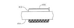
図7乃至図11において、一定の外科ステープルおよび切断用の器具310のための電気作動型の抗バックアップ機構40の一例の態様は一定の発射ロッド314を密接に囲っている一定の巻付型の抗バックアップばね312を含む。特に、この巻付型抗バックアップばね312の先端部316は長手方向に延在している。特に図8において、一定のフレーム基板322の中に形成されている一定の上方に開口しているアクチュエータ凹部320は一定の先端側の垂直のスロット326を伴う一定の概ね方形のプリズム開口部324を含み、このスロット326は巻付型の抗バックアップばね312の先端部316を受容してその回転を阻止する。さらに、上記の上方に開口しているアクチュエータ凹部320の左側の垂直なスロット328が当該上方に開口しているアクチュエータ凹部320の右の基端側の面に対して位置決めされている一定のEAP型遮断アクチュエータ330により左側に回転する時に巻付型抗バックアップばね312のひっくり返した基端部328を受容するように配列されている。図11において、上記のひっくり返した基端部328が左側に回転する時に締め付ける一定の方向に巻付型の抗バックアップばね312が巻かれている。なお、このEAP型アクチュエータ330のエネルギー供給された状態(例えば、横方向に拡張しているか、横方向に収縮している状態)および巻付型抗バックアップばね312の締め付けの方向がバイアス付勢された係止状態またはバイアス付勢された係止解除状態に対応して選択可能であることを認識する必要がある。 7-11, an example embodiment of an electrically actuated
あるいは、一定の巻き付けたばね(図示されていない)が、長さの変化を行なうためにその巻き付けたばねの長さに沿って一定の電気的なアクチュエータを伴って、長手方向に短小化されて一定の半径方向に拡張した係止解除状態になることができ、さらに、長手方向に伸ばされて一定の半径方向に収縮した係止状態になることができることを認識する必要がある。あるいは、上記の巻き付けたばねの一端部を一定のフレーム基板に対して固定して、一定の電気的なアクチュエータによりその巻き付けたばねの自由な端部を上記の変化を行なうためにフレーム基板に対して移動することができる。 Alternatively, a constant wound spring (not shown) is shortened in the longitudinal direction with a constant electrical actuator along the length of the wound spring to effect a change in length. It should be recognized that the unlocked state can be expanded radially, and that it can be extended in the longitudinal direction and contracted in a certain radial direction. Alternatively, one end of the wound spring is fixed with respect to a fixed frame substrate, and the free end of the wound spring is moved with respect to the frame substrate to perform the above change by a fixed electric actuator. can do.
特に図8において、一定の固定型のカラー332は一定の先端側の導電性の周辺リング334を有しており、このリング334には一定の接触部材336が打ち込まれており、この接触部材336はフレーム基板322により形成されている一定の電気的な接地経路と共にEAP型遮断アクチュエータ330に対応する1個の電極として作用する。図7乃至図10において、一定の基端側に突出しているアーム338が固定型カラー332の上部基端側の表面に取り付けられていてハンドル・ハウジング340に係合して固定型カラー332の回転または長手方向の移動を阻止している。図8および図9において、一定の閉鎖スリーブ342が閉鎖時の移動中に接触部材336の延伸部分に適合するように寸法付けられている細長い上部孔344を有している。この場合に、一定の回転ノブ(図示されていない)が閉鎖スリーブ342の細長い上部孔344およびフレーム基板322の中の上方に開口しているアクチュエータ凹部320に重なっていることを認識する必要がある。 In particular, in FIG. 8, the fixed
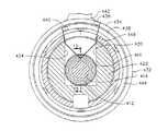
次に、図12乃至図15において、一定の外科ステープルおよび切断用の器具410のための電気作動型の抗バックアップ機構40の一例の態様は一定の発射ロッド414を密接に囲っていてエネルギー供給される時に半径方向に拡張する一定のEAP分割型の円筒形のアクチュエータ412を含む。さらに、一定の剛性のスリーブ316が上記EAP分割型の円筒形のアクチュエータ412を囲っていて、内側に拡張させて発射ロッド414に対して結合して接触させている。特に図12において、一定のフレーム基板422の中に形成されている一定の上方に開口しているアクチュエータ凹部420は一定の概ね方形のプリズム開口部424を含む。さらに、一定の固定型のカラー432は第1の接触部材436が打ち込まれている一定の外側で先端側の導電性の周辺リング434および第2の接触部材440が打ち込まれている一定の内側で先端側の導電性の周辺リング438を有しており、これらの接触部材はEAP分割型の円筒形のアクチュエータ412のための電極(すなわち、カソードおよびアノード)としてそれぞれ作用する。さらに、一定の基端側に突出しているアーム442が固定型カラー432の一定の上部基端側の表面に取り付けられていて一定のハンドル・ハウジング444に係合して固定型カラー432の回転および長手方向の移動を阻止している。さらに、図12乃至図14において、一定の閉鎖スリーブ446は閉鎖状態の移動中に各接触部材436,440の延伸部分に適合するように寸法付けられている一定の細長い上部孔448を有している。この場合に、一定の回転ノブ(図示されていない)が閉鎖スリーブ446の細長い上部孔448およびフレーム基板422の中の上方に開口しているアクチュエータ凹部420に重なっていることを認識する必要がある。 Next, in FIGS. 12-15, an example embodiment of an electrically operated
図16および図17において、一定の外科ステープルおよび切断用の器具510のための電気作動型の抗バックアップ機構40の一例の態様は一定の発射ロッド514を密接に囲っていて、当該発射ロッド514に対して結合して接触する状態を形成する一定の緩和されて収縮した状態を有し、エネルギー供給される時にその結合して接触した状態から半径方向に拡張する一定のEAP型の円筒形のアクチュエータ412を含む。この場合に、一定のフレーム基板522の中に形成されている一定の上方に開口しているアクチュエータ凹部520は一定の概ね方形のプリズム開口部524を含む。さらに、一定の固定型のカラー532は第1の接触部材536が打ち込まれている一定の外側で先端側の導電性の周辺リング534および第2の接触部材540が打ち込まれている一定の内側で先端側の導電性の周辺リング538を有しており、これらの接触部材はEAP分割型の円筒形のアクチュエータ512のための電極(すなわち、カソードおよびアノード)としてそれぞれ作用する。さらに、一定の基端側に突出しているアーム542が固定型カラー532の一定の上部基端側の表面に取り付けられていて一定のハンドル・ハウジング(図示されていない)に係合して固定型カラー532の回転および長手方向の移動を阻止している。さらに、図16において、一定の閉鎖スリーブ546は閉鎖状態の移動中に各接触部材536,540の延伸部分に適合するように寸法付けられている一定の細長い上部孔548を有している。この場合に、一定の回転ノブ(図示されていない)が閉鎖スリーブ546の細長い上部孔548およびフレーム基板522の中の上方に開口しているアクチュエータ凹部520に重なっていることを認識する必要がある。 16 and 17, an example embodiment of an electrically actuated
以上において、本発明が幾つかの実施形態の説明により例証されていて、これらの例示的な実施形態が相当に詳細に説明されているが、添付の特許請求の各項の範囲をこれらの詳細に制限するか何らかの意味で限定することは本特許出願人の意図するところではない。すなわち、さらに別の利点および変更が当業界における熟練者において容易に明らかになると考えられる。 While the invention has been illustrated by way of example in the description of several embodiments, and these exemplary embodiments have been described in considerable detail, the scope of the appended claims should be considered as those details. It is not intended by the applicant of this patent to limit to or in any way. That is, further advantages and modifications will be readily apparent to those skilled in the art.
上記用語の「基端側(proximal)」および「先端側(distal)」は一定の臨床医が一定の器具のハンドルを把持することに関連して本明細書において用いられていることを認識する必要がある。従って、エンド・エフェクター12はさらに基端側のハンドル20に対して先端側である。また、「前方(front)」および「後方(back)」等のような類似の用語は先端側および基端側に対してそれぞれ同様に対応している。さらに、便宜上および明瞭化のために、「垂直(vertical)」および「水平(horizontal)」等のような空間的な用語は書く図面に関連して本明細書において用いられていることを認識する必要がある。しかしながら、種々の外科器具が多様な配向および位置において用いられ、これらの用語は限定および絶対化を目的としていない。 The above terms “proximal” and “distal” recognize that certain clinicians are used herein in connection with grasping the handle of certain instruments. There is a need. Accordingly, the
本発明は内視鏡式の処置および装置に関して論じられているが、「内視鏡(式)(endoscopic)」等のような用語の本明細書における使用が本発明を一定の内視鏡管(すなわち、トロカール)と共にのみ使用するための一定の外科ステープルおよび切断用の器具に限定すると解釈するべきではない。これに反して、本発明は種々の腹腔鏡式の処置ならびに切開式の処置を含むがこれらに限定されない接近手段が一定の小さな切開部分に限定されている任意の処置または方法において有用性を見出すことができると考えられる。 Although the present invention is discussed in terms of endoscopic procedures and devices, the use of terms such as “endoscopic” and the like herein makes the present invention an endoscope tube. (Ie, trocar) should not be construed as limited to certain surgical staples and cutting instruments for use only. On the contrary, the present invention finds utility in any procedure or method in which the access means, including but not limited to various laparoscopic procedures as well as open procedures, are limited to certain small incisions. It is considered possible.
本発明に一貫している適用例は単一回発射ストローク型の器具ならびに一定の連結型のラックではなく一定の連続固定型のラックを伴う器具を含むことができる。 Applications consistent with the present invention can include single firing stroke type instruments as well as instruments with a fixed fixed rack rather than a fixed linkage rack.
別の例として、一定のロッキング・ブーツ型の抗バックアップ・レバーを配置して結合状態に接触させることができる。さらに、一定の手動式のロッキング・ブーツ型の抗バックアップ・レバーが2004年6月30日に出願されているホワイタクル(Whitacre)他に譲渡されている「サージカル・ステープリング・インストルメント・インコーポレイテイング・ア・マルチストローク・ファイアリング・メカニズム・ハビング・ア・ロータリー・トランスミッション(SURGICAL STAPLING INSTRUMENT INCORPORATING A MULTISTROKE FIRING MECHANISM HAVING A ROTARY TRANSMISSION)」を発明の名称とする米国特許出願第10/881,105号において開示されており、この文献の開示はその内容全体が本明細書において参考文献として含まれる。 As another example, a locking boot type anti-backup lever can be placed in contact with the coupled state. In addition, certain manual rocking boot-type anti-backup levers have been transferred to Whitcre et al., Filed June 30, 2004, “Surgical Stapling Instrument Incorporating. US Patent Application No. 10 / 881,105 entitled “SURGICAL STAPLING INSTRUMENT INCORPORATING A MULTISTROKE FIRING MECHANISM HAVING A ROTARY TRANSMISSION” The disclosure of this document is hereby incorporated by reference in its entirety.
本発明は外科医により必要とされる過度の手の力を伴わずに一定の長いエンド・エフェクターを作動する一定の多数回発射ストローク式のハンドルを好都合に含む一定の外科ステープルおよび切断用の器具に適用できる。 The present invention provides a surgical stapling and cutting instrument that advantageously includes a multi-fire stroke handle that operates a long end effector without the excessive hand force required by the surgeon. Applicable.
本発明の具体的な実施態様は以下のとおりである。
(1)外科器具において、
一定のエンド・エフェクター、
前記エンド・エフェクターに先端側において連結している一定の長手方向に往復動する発射ロッド、
前記エンド・エフェクターに取り付けられている一定の先端部を有していて前記発射ロッドを案内するように操作可能に構成されている一定の軸部、
前記軸部の一定の基端部に取り付けられていて一連のストロークにおいて前記発射ロッドを先端側に進行させるように操作可能に構成されている一定のハンドル、および
前記ハンドルに対して物理的に取り付けられていて一定の電気的な信号に応じて前記発射部材と共に一定の無結合状態の位置と一定の結合状態の位置との間において移動することによりその長手方向の移動を阻止する一定の電気的なアクチュエータを備えている外科器具。
(2)前記電気的なアクチュエータが一定の電気活性なポリマーのアクチュエータを含む実施態様1に記載の外科器具。
(3)前記電気的なアクチュエータがさらに前記発射ロッドを囲んでいて当該発射ロッドに対して垂直な係止解除状態にある時に無結合状態の接触をしてその垂直状態から一定の角度で傾斜している時の係止状態にある時に結合状態の接触をするように寸法付けられている一定の係止プレートの貫通穴を含み、当該電気的なアクチュエータが前記係止プレートを前記係止解除状態および係止状態から成る群の内の一定の選択された状態から別の状態に移動するように位置決めされている実施態様1に記載の外科器具。
(4)さらに、前記係止プレートを係止状態に付勢する一定の弾性部材を備えており、当該弾性部材と反対側の前記発射ロッドの先端側への移動によりその係止プレートが係止解除状態に移動し、前記電気的なアクチュエータが前記弾性部材を活性化する場合に選択的に対向して打ち勝つための一定の抗バックアップ・カム・チューブの位置を含む実施態様3に記載の外科器具。
(5)前記電気的なアクチュエータが活性化時に前記抗バックアップ・カム・チューブを前記ハンドルから先端側に押し出すために長手方向に拡張するように操作可能に構成されている電気活性なポリマーのアクチュエータを含む実施態様4に記載の外科器具。Specific embodiments of the present invention are as follows.
(1) In surgical instruments,
A certain end effector,
A firing rod reciprocating in a certain longitudinal direction connected to the end effector at the distal end side;
A shaft having a tip attached to the end effector and configured to be operable to guide the firing rod;
A fixed handle attached to a fixed base end of the shaft and configured to be operable to advance the firing rod toward the distal end in a series of strokes; and physically attached to the handle A constant electrical movement that moves with the firing member between a constant uncoupled position and a constant coupled position in response to a constant electrical signal to prevent longitudinal movement thereof. Surgical instrument with a flexible actuator.
The surgical instrument of claim 1, wherein the electrical actuator comprises an electroactive polymer actuator.
(3) When the electric actuator further surrounds the firing rod and is in the unlocked state perpendicular to the firing rod, the electrical actuator is brought into a non-coupled state and tilted at a certain angle from the vertical state. A locking plate through-hole dimensioned to make a combined contact when in a locked state, the electrical actuator holding the locking plate in the unlocked state The surgical instrument of claim 1, wherein the surgical instrument is positioned to move from one selected state to another state of the group consisting of and a locked state.
(4) Furthermore, a certain elastic member that urges the locking plate to the locked state is provided, and the locking plate is locked by the movement of the firing rod on the side opposite to the elastic member to the tip side. The surgical instrument of embodiment 3, including a position of an anti-backup cam tube for moving to a release state and selectively overcoming when the electrical actuator activates the resilient member. .
(5) an electroactive polymer actuator configured to be operable to extend longitudinally to push the anti-backup cam tube from the handle to the distal side when the electric actuator is activated; Embodiment 5. The surgical instrument of embodiment 4, comprising.
(6)さらに、
前記抗バックアップ・カム・チューブに取り付けられている一定の基端側に突出しているヨーク、および
前記抗バックアップ・カム・チューブを手動により作動して前記係止プレートを解除するために前記基端側に突出しているヨークに一定の解除動作を伝達するように操作可能に構成されている一定の手動解除機構を備えている実施態様4に記載の外科器具。
(7)さらに、使用者の作動に対応して操作可能に構成されている一定の手動解除制御手段を備えており、前記手動解除機構がその手動解除制御手段から前記解除動作を伝達するように操作可能に構成されている実施態様6に記載の外科器具。
(8)さらに、前記発射ロッドに対して前記ハンドルの中の動作のために連結されている一定の係止解除要素、前記基端側に突出しているヨークを先端側に押し出して前記係止プレートを係止解除するために前記発射ロッドの完全な発射の移動に対応する一定の先端側の位置まで前記係止解除要素に対応して移動する一定の抗バックアップ解除レバーを備えている実施態様6に記載の外科器具。
(9)前記電気的なアクチュエータが前記発射ロッドを半径方向に含む一定の巻き付けられたばね、および前記発射ロッドに結合して接触している一定の比較的に小さな直径の一定の係止状態および前記発射ロッドに無結合の状態で接触している一定の比較的に大きな直径の一定の係止解除状態から成る群における選択された一つとその別の状態との間において前記巻き付けられたばねの内径を変化するように操作可能に構成されている一定の電気的な装置を含む実施態様1に記載の外科器具。
(10)前記巻き付けられたばねがさらに前記軸部により回転に対抗して保持されている第1の端部および一定の半径方向に延伸している端部を含み、前記電気的なアクチュエータが前記半径方向に延伸している端部を回転して前記選択された状態を実行するように位置決めされている一定の電気活性なポリマーのアクチュエータを含む実施態様9に記載の外科器具。(6) Furthermore,
A proximally protruding yoke attached to the anti-backup cam tube, and the proximal side for manually actuating the anti-backup cam tube to release the locking plate Embodiment 5. The surgical instrument of embodiment 4, comprising a manual release mechanism configured to be operable to transmit a release action to the yoke projecting on.
(7) Further, it is provided with a certain manual release control means configured to be operable in response to the operation of the user, so that the manual release mechanism transmits the release operation from the manual release control means. Embodiment 7. The surgical instrument of embodiment 6, wherein the surgical instrument is configured to be operable.
(8) Further, a certain unlocking element connected to the firing rod for operation in the handle, and a yoke protruding to the proximal end side are pushed to the distal end side to push the locking plate Embodiment 6 comprising an anti-backup release lever that moves in response to the unlocking element to a position on the distal end corresponding to a full firing movement of the firing rod to unlock The surgical instrument described in 1.
(9) a wound spring in which the electrical actuator includes the firing rod in a radial direction, and a relatively small diameter constant locking state coupled to and in contact with the firing rod; and The inner diameter of the wound spring between a selected one in the group consisting of a constant unlocked state of a relatively large diameter and in contact with the firing rod in an uncoupled state; The surgical instrument of embodiment 1, comprising an electrical device operably configured to change.
(10) The wound spring further includes a first end portion held against the rotation by the shaft portion and an end portion extending in a certain radial direction, and the electric actuator includes the radius. The surgical instrument of
(11)前記軸部がさらに前記ハンドルにより長手方向に位置決めされている一定のフレーム基板を含み、前記電気的なアクチュエータが前記発射ロッドを囲み前記フレーム基板に取り付けられている一定の電機活性なポリマーのスリーブを含む実施態様1に記載の外科器具。
(12)前記電気活性なポリマーのスリーブが一定の電力供給状態および一定の無電力供給状態の内の選択された一つの状態にある時の結合している接触状態に対応する一定の内径および前記の選択されない状態にある時の結合していない接触状態に対応する一定の外径を有するように操作可能に構成されている実施態様11に記載の外科器具。
(13)一定の無電力供給状態の緩和した状態にある時の前記電気活性なポリマーのスリーブが結合していない係止解除の接触状態に対応する前記発射ロッドよりも大きい一定の内径を有し、一定の電力供給状態が前記電気活性なポリマーのスリーブの一定の半径方向の厚さを拡張し、この場合に、前記軸部が前記電気活性なポリマーのスリーブの外側への拡張を拘束して電力供給時にその電気活性なポリマーのスリーブを前記発射ロッドに対して結合している接触状態にするように操作可能に構成されている実施態様11に記載の外科器具。
(14)前記エンド・エフェクターが一定のステープル供給組立体を含む実施態様1に記載の外科器具。
(15)さらに、
一定のエンド・エフェクター、
一定のハンドル、
前記ハンドルに前記エンド・エフェクターを取り付けている一定のフレーム基板および前記ハンドルと前記エンド・エフェクターとの間における長手方向の往復動作のために案内されている一定の発射部材を含む一定の細長い軸部、
前記ハンドルに対して移動するために取り付けられている一定の発射トリガー、
前記発射トリガーの各発射ストロークと共に増進的に前記発射部材を先端側に進行させるように操作可能に構成されている前記ハンドルの中の一定の多数回ストローク発射式の機構、
前記発射部材を一定の後退した位置に押し動かす一定の後退バイアス用の部材、および
前記発射トリガーの各発射ストロークの間に前記発射部材の偶発的な後退を防止するためにその発射部材を電気的に係止および係止解除するための一定の手段を備えている実施態様1に記載の外科器具。(11) An electroactive polymer, wherein the shaft portion further includes a frame substrate positioned longitudinally by the handle, and the electric actuator surrounds the firing rod and is attached to the frame substrate The surgical instrument of claim 1, including any of the sleeves.
(12) a constant inner diameter corresponding to a combined contact state when the electroactive polymer sleeve is in a selected one of a constant power supply state and a constant non-power supply state; and The surgical instrument of embodiment 11, wherein the surgical instrument is operably configured to have a constant outer diameter corresponding to an uncoupled contact condition when in a non-selected condition.
(13) having a constant inner diameter larger than the firing rod corresponding to the unlocked contact state where the electroactive polymer sleeve is not coupled when in a relaxed state of a constant no-power supply state; A constant power supply condition expands a constant radial thickness of the electroactive polymer sleeve, in which case the shank constrains the expansion of the electroactive polymer sleeve to the outside. The surgical instrument of claim 11, wherein the surgical instrument is operatively configured to place the electroactive polymer sleeve in contact with the firing rod when powered.
14. The surgical instrument of embodiment 1, wherein the end effector includes a staple supply assembly.
(15) Furthermore,
A certain end effector,
Set handle,
An elongate shaft comprising a frame substrate mounting the end effector to the handle and a firing member guided for longitudinal reciprocation between the handle and the end effector; ,
A constant firing trigger attached to move relative to the handle;
A fixed multi-stroke firing mechanism in the handle configured to be operable to progressively advance the firing member forward with each firing stroke of the firing trigger;
A constant reverse biasing member that pushes the firing member to a certain retracted position, and the firing member is electrically connected to prevent accidental retraction of the firing member during each firing stroke of the firing trigger. The surgical instrument of embodiment 1, comprising certain means for locking and unlocking.
(16)外科器具において、
一定のエンド・エフェクター、
一定のハンドル、
前記ハンドルに前記エンド・エフェクターを取り付けている一定のフレーム基板および前記ハンドルと前記エンド・エフェクターとの間における長手方向の往復動作のために案内されている一定の発射部材を含む一定の細長い軸部、
前記ハンドルに対して移動するために取り付けられている一定の発射トリガー、
前記発射トリガーの各発射ストロークと共に増進的に前記発射部材を先端側に進行させるように操作可能に構成されている前記ハンドルの中の一定の多数回ストローク発射式の機構、
前記発射部材に一定の後退用のバイアス力を加えるために前記ハンドルの中に位置決めされている一定の後退バイアス用の部材、
前記発射部材と共に一定の係止状態と一定の係止解除状態との間において移動するように操作可能に構成されている一定の電気的なアクチュエータを含む一定の抗バックアップ機構、および
前記電気的なアクチュエータを活性化するように操作可能に構成されている制御回路を備えている外科器具。
(17)前記抗バックアップ機構がさらに、
垂直である時に前記発射ロッドから離脱して傾斜しているときに係止されるように寸法付けられている一定の貫通穴を有する一定の係止プレート、
前記係止プレートを一定の後方の傾斜した角度の位置まで付勢する一定のばね、
前記ばねに対向している一定のカム部材、および
前記カム部材および前記係止プレートをさらに前記係止状態に移動するように位置決めされている一定の電気活性なポリマーのアクチュエータを備えている実施態様16に記載の外科器具。
(18)さらに、前記軸部により回転に対抗して保持されている第1の端部および一定の半径方向に延伸している端部を含む一定の巻き付けられたばねを備えており、前記電気的なアクチュエータが前記半径方向に延伸している端部を回転して前記巻き付けられたばねの内径を変化することにより前記係止状態および前記係止解除状態から成る群から選択される状態の一定の変化を実行するように位置決めされている一定の電気活性なポリマーのアクチュエータを含む実施態様16に記載の外科器具。
(19)前記細長い軸部がさらに前記ハンドルにより長手方向に位置決めされている一定のフレーム基板を含み、前記電気的なアクチュエータが前記発射ロッドを含み前記フレーム基板に取り付けられていて一定の電力供給状態および一定の無電力供給状態の内の選択された一つにある時の結合している接触状態に対応する一定の内径および前記選択されない状態にある時の結合していない接触状態に対応する一定の比較的に大きな内径を有するように操作可能に構成されている一定の電気活性なポリマーのスリーブを含む実施態様16に記載の外科器具。
(20)一定の無電力供給状態の緩和した状態にある時の前記電気活性なポリマーのスリーブが結合していない係止解除の接触状態に対応する前記発射ロッドよりも大きい一定の内径を有し、一定の電力供給状態が前記電気活性なポリマーのスリーブの一定の半径方向の厚さを拡張し、この場合に、前記フレーム基板が前記電気活性なポリマーのスリーブの外側への拡張を拘束して電力供給時にその電気活性なポリマーのスリーブを前記発射ロッドに対して結合している接触状態にするように操作可能に構成されている実施態様19に記載の外科器具。(16) In surgical instruments,
A certain end effector,
Set handle,
An elongate shaft comprising a frame substrate mounting the end effector to the handle and a firing member guided for longitudinal reciprocation between the handle and the end effector; ,
A constant firing trigger attached to move relative to the handle;
A fixed multi-stroke firing mechanism in the handle configured to be operable to progressively advance the firing member forward with each firing stroke of the firing trigger;
A constant reverse biasing member positioned within the handle to apply a constant reverse biasing force to the firing member;
An anti-backup mechanism including an electrical actuator operatively configured to move with the firing member between a locked state and a locked state; and the electrical A surgical instrument comprising a control circuit operatively configured to activate an actuator.
(17) The anti-backup mechanism further includes
A locking plate having a through-hole dimensioned to be locked when tilted away from the firing rod when being vertical;
A constant spring that biases the locking plate to a position at a fixed rearward angle;
An embodiment comprising: a cam member facing the spring; and an electroactive polymer actuator positioned to further move the cam member and the locking plate to the locked state. The surgical instrument according to
(18) and a constant wound spring including a first end held against rotation by the shaft and an end extending in a radial direction. A constant change in a state selected from the group consisting of the locked state and the unlocked state by changing the inner diameter of the wrapped spring by rotating the radially extending end of the actuator.
(19) The elongate shaft portion further includes a frame substrate positioned longitudinally by the handle, and the electric actuator includes the firing rod and is attached to the frame substrate, and is in a constant power supply state. And a constant inner diameter corresponding to a coupled contact state when in a selected one of a certain unpowered state and a constant corresponding to an uncoupled contact state when in the
(20) having a constant inner diameter larger than the firing rod corresponding to the unlocked contact state in which the electroactive polymer sleeve is not coupled when in a relaxed state of a constant no-power supply state; A constant power supply condition extends a constant radial thickness of the electroactive polymer sleeve, in which case the frame substrate constrains the expansion of the electroactive polymer sleeve to the outside.
10 外科ステープルおよび切断用の器具
12 エンド・エフェクター(ステープル供給組立体)
14 アンビル
16 細長い(ステープル)通路
18 細長い軸部
20 ハンドル
21 フレーム基板
22 実行部分
24 閉鎖チューブ
25 発射ロッド
25a 発射ロッド
26 ハンドル・ハウジング
27 回転ノブ
28 閉鎖トリガー
30 ピストル・グリップ
32 多数回ストローク式発射トリガー
34,36 左右のインジケータ・ホイール
38 手動後退レバー
40 機械−電気混成型抗バックアップ機構
41 閉鎖解除ボタン
42 抗バックアップ用電気式アクチュエータ
44 制御モジュール
46 電池
48 電力ボタン
50 発射トリガー位置センサー
54 ホール効果式トランスデューサ
56 抗バックアップ用係止プレート
58 係止プレートの貫通穴
60 弾性部材
60a 抗バックアップ用圧縮ばね
62 下方タブ取付部材
64 フレーム基板の基端側下方リップ部
66 抗バックアップ用係止プレートの下方エッジ部分の孔
70 抗バックアップ用カム・チューブ
72 基端側に配向している抗バックアップ用カム・ヨーク
72a 短小化したカム・ヨーク
74,76 EAP型の円筒形のアクチュエータ
78 細い先端側コイル
80 発射ロッドの細化した部分
82 広げられた基端側コイル
90 回転ノブの中の内側突出部
92 閉鎖チューブの中の比較的に長い側部開口部
93 閉鎖トリガー・ピン
94 閉鎖トリガーの上側部分
96 閉鎖ヨーク
98 閉鎖リンク
100 閉鎖ヨーク・ピン
102 閉鎖リンク・ピン
104 閉鎖トリガー引張ばね
106 基端側頂上部分
108 後方ノッチ部
110 旋回式係止アーム
112 中央の側方ピボット部材
114 圧縮ばね
118 発射トリガー・ピン
120 連結伝達型発射機構
122 組み合わせ式の引張/圧縮ばね
124 不動端部
126 ばねの移動端部
128 スチール・バンドの基端側の後退している端部
130 スチール・バンド
132 スチール・バンドの先端側に配置されている端部
134 スチール・バンド用の前方リンクにおける取付部分
136a乃至136d リンク(フロント・リンク136a)
140 連結型ラック
141 ラック・ガイド・チューブ
142 基端側に開口している内部キャビティ
143 比較的に小形の先端側開口部
144,145 左右の把持部分
146,147 閉鎖ヨーク・カバーの中の細長いスロット
148 ラック・チャネル・カバー
149 基端側側面の凹部
150 タング
152 ラック・チャネル
154 抗バックアップ用放出レバーにおける下部基端側のカム
156 抗バックアップ用放出レバー
158 ピン・レセプタクル
160 円形ピン
162 縦方向に細長い孔
164 基端側に開口しているチャネル(通路)
166 基端側に水平な部分
168 上方および先端側に角度の付いた部分
170 右側後方のピン
172 遮断構造
174 抗バックアップ用放出レバーの先端部
176 右側前方のピン
178 先端側に開口している段構造
180 圧縮ばね
182 左側フック
184 右側外殻部分の中のフック
186 上方に突出しているリセット・タング
188 下部先端側のカム
190 発射トリガーの上側部分
192 発射トリガー用引張ばね
194 ばね付勢側部つめ機構
196 傾斜した右側トラック
198 基端側および右側に面している傾斜した表面
200 つめ摺動部(シャトル)
202 左右の下部ガイド
204 左側トラック
206 右側トラック
208 閉鎖ヨーク・レール
212 圧縮ばね
214 閉鎖ヨーク・レール上の上部基端側の位置におけるフック
216 つめ摺動部の先端の右側におけるフック
218 つめ遮断部
220 つめ遮断部とつめ摺動部との間の垂直後方のピン
222 キック−アウト遮断凹部
224 キック−アウト遮断部
226 キック−アウト遮断部の中の垂直ピン
228 つめ型ばね凹部
230 つめ型ばね
232 小形コイルばね
234 形付けしたリップ
236 形付けしたリップの中の隆起部分
240 前方遊び歯車
242 歯付きの上部左側表面
244 後方遊び歯車
246 小形右側ラチェット歯車
248 前方遊び車軸
250 後方遊び車軸
260 手動後退レバーのハブ
262 垂直縦方向に整列したスロット
264 ハブの横方向の貫通孔
266 上部凹部
268 基端側に配向している係止用のつめ
270 右側横ピン
272 L字形ばねタブ
274 持上げ構造
276 コイルばね
278 右側湾曲隆起部
310 外科ステープルおよび切断用の器具
312 巻付型抗バックアップばね
314 発射ロッド
316 巻付型抗バックアップばねの先端部
320 上方に開口したアクチュエータ凹部
322 フレーム基板
324 方形のプリズム開口部
326 先端側の垂直スロット
328 左側垂直スロット
328 ひっくり返した基端部
330 EAP型遮断アクチュエータ
332 固定カラー
334 先端側導電性周辺リング
336 接触部材
338 基端側に突出しているアーム
340 ハンドル・ハウジング
342 閉鎖スリーブ
344 細長い上部孔
410 外科ステープルおよび切断用の器具
412 EAP分割型円筒形アクチュエータ
414 発射ロッド
416 剛性のスリーブ
420 上方に開口しているアクチュエータ凹部
422 フレーム基板
424 方形のプリズム開口部
432 固定カラー
434 外側先端側導電性周辺リング
436 第1の接触部材
438 内側先端側導電性周辺リング
440 第2の接触部材
442 基端側に突出しているアーム
444 ハンドル・ハウジング
446 閉鎖スリーブ
448 細長い上部孔
510 外科ステープルおよび切断用の器具
512 EAP型円筒形アクチュエータ
514 発射ロッド
520 上方に開口しているアクチュエータ凹部
522 フレーム基板
524 方形のプリズム開口部
532 固定カラー
534 外側先端側導電性周辺リング
536 第1の接触部材
538 内側先端側導電性周辺リング
540 第2の接触部材
542 基端側に突出しているアーム
546 閉鎖スリーブ
548 細長い上部孔
10 Surgical Stapling and
14 Anvil 16 Elongated (staple) passage 18 Elongated shaft portion 20 Handle 21 Frame substrate 22 Execution portion 24 Closing tube 25 Firing rod 25a Firing rod 26 Handle housing 27 Rotating knob 28 Closure trigger 30 Pistol grip 32 Multiple stroke firing trigger 34, 36 Left and right indicator wheels 38 Manual reversing lever 40 Mechanical-electric hybrid anti-backup mechanism 41 Closure release button 42 Anti-backup electric actuator 44 Control module 46 Battery 48 Power button 50 Launch trigger position sensor 54 Hall effect transducer 56 Anti-backup locking plate 58 Locking plate through-hole 60 Elastic member 60a Anti-backup compression spring 62 Lower tab mounting member 64 Base frame side lower side Anti-backup cam tube 72 Anti-backup cam yoke 72a oriented toward the base end Shortened cam yoke 74, 76 EAP type Cylindrical actuator 78 thin distal coil 80 firing rod thinned portion 82 widened proximal coil 90 inner protrusion 92 in rotary knob relatively long side opening 93 in closure tube Closure trigger pin 94 Closure trigger upper portion 96 Closure yoke 98 Closure link 100 Closure yoke pin 102 Closure link pin 104 Closure trigger tension spring 106 Proximal top portion 108 Back notch 110 Pivoting locking arm 112 Central Side pivot member 114 Compression spring 118 Firing trigger pin 120 Connection transmission type Shooting mechanism 122 Combined tension / compression spring 124 Non-moving end 126 Spring moving end 128 Steel band proximal end 130 Steel band 132 Located on the distal end of the steel band Ends 134 Attachment portions 136a to 136d on the front link for the steel band link (front link 136a)
140
166
202 Left and right lower guides 204 Left track 206 Right track 208 Closure yoke rail 212 Compression spring 214 Hook 216 at the upper proximal end position on the closure yoke rail 218 Hook 218 pawl blocking portion 220 at the right end of the sliding part Vertical rear pin 222 between the pawl blocking portion and the pawl sliding portion 222 Kick-out blocking recess 224 Kick-out blocking portion 226 Vertical pin 228 in the kick-out blocking portion 230 Pawl spring recess 230 Pawl spring 232 Small Coil spring 234 shaped lip 236 raised portion 240 in shaped lip forward play gear 242 toothed upper left surface 244 rear play gear 246 small right ratchet gear 248 forward play axle 250 rear play axle 260 Hub 262 Vertically aligned threads Lot 264 Hub transverse through hole 266 Upper recess 268 Proximal locking pawl 270 Right lateral pin 272 L-shaped spring tab 274 Lifting structure 276 Coil spring 278 Right curved ridge 310 Surgical staple and Cutting tool 312 Wound anti-backup spring 314 Firing rod 316 Winding anti-backup spring tip 320 Actuator recess 322 opened upward Frame substrate 324 Square prism opening 326 Tip vertical slot 328 Left vertical slot 328 inverted base end 330 EAP type shut-off actuator 332 fixed collar 334 distal end conductive peripheral ring 336 contact member 338 proximal end projecting arm 340 handle housing 342 closure sleeve 344 elongate upper hole 410 surgical step Pull and cutting instrument 412 EAP split cylindrical actuator 414 Firing rod 416 Rigid sleeve 420 Opening actuator recess 422 Frame substrate 424 Square prism opening 432 Fixed collar 434 Outer tip side conductive peripheral ring 436 First contact member 438 Inner distal conductive peripheral ring 440 Second contact member 442 Proximal projecting arm 444 Handle housing 446 Closure sleeve 448 Elongated upper hole 510 Surgical staple and cutting instrument 512 EAP type Cylindrical actuator 514 Firing rod 520 Actuator recess 522 opened upward Frame substrate 524 Square prism opening 532 Fixed collar 534 Outside tip side conductive peripheral ring 536 First contact member 538 Inside End side conductive peripheral ring 540 second contact member protrudes into 542 proximal arm 546 closure sleeve 548 elongated upper hole
Claims (1)
Translated fromJapaneseエンド・エフェクターと、
前記エンド・エフェクターに先端側において連結している長手方向に往復動する発射部材と、
前記エンド・エフェクターに取り付けられている先端部を有していて前記発射部材を案内するように操作可能に構成されている軸部と、
前記軸部の基端部に取り付けられていて一連のストロークにおいて前記発射部材を先端側に進行させるように操作可能に構成されているハンドルと、
前記ハンドルに対して物理的に取り付けられていて電気的な信号に応じて長手方向の移動を阻止するために前記発射部材に対する無結合状態の位置と結合状態の位置との間を移動する電気的なアクチュエータと、
を含み、
前記電気的なアクチュエータは、電気活性なポリマーのアクチュエータを含み、
前記軸部は、前記ハンドルによって長手方向に位置決めされるフレーム基板を更に含み、前記電気活性なポリマーのアクチュエータは、前記フレーム基板に取り付けられて前記発射部材を少なくとも部分的に囲む電気活性なポリマーのスリーブを含む、外科器具。In surgical instruments,
End effector,
A firing member reciprocating in the longitudinal direction connected to the end effector on the distal end side;
A shaft portion having a tip attached to the end effector and configured to be operable to guide the firing member;
A handle attached to the proximal end of the shaft and configured to be operable to advance the firing member toward the distal end in a series of strokes;
Electrically attached to the handle and moving between an uncoupled position and a coupled position with respect to the firing member to prevent longitudinal movement in response to an electrical signal An actuator,
Including
The electrical actuator includes an electroactive polymer actuator;
The shank further includes a frame substrate longitudinally positioned by the handle, and the electroactive polymer actuator is attached to the frame substrate and at least partially surrounds the firing member. Surgical instruments, including sleeves.
Applications Claiming Priority (4)
| Application Number | Priority Date | Filing Date | Title |
|---|---|---|---|
| US59169404P | 2004-07-28 | 2004-07-28 | |
| US60/591,694 | 2004-07-28 | ||
| US11/181,046US7513408B2 (en) | 2004-07-28 | 2005-07-14 | Multiple firing stroke surgical instrument incorporating electroactive polymer anti-backup mechanism |
| US11/181,046 | 2005-07-14 |
Publications (3)
| Publication Number | Publication Date |
|---|---|
| JP2006034981A JP2006034981A (en) | 2006-02-09 |
| JP2006034981A5 JP2006034981A5 (en) | 2011-03-31 |
| JP5128058B2true JP5128058B2 (en) | 2013-01-23 |
Family
ID=35285607
Family Applications (1)
| Application Number | Title | Priority Date | Filing Date |
|---|---|---|---|
| JP2005217100AExpired - Fee RelatedJP5128058B2 (en) | 2004-07-28 | 2005-07-27 | Multi-shot stroke surgical instrument including an electroactive polymer anti-backup mechanism |
Country Status (8)
| Country | Link |
|---|---|
| US (1) | US7513408B2 (en) |
| EP (1) | EP1621140B1 (en) |
| JP (1) | JP5128058B2 (en) |
| KR (1) | KR20060048877A (en) |
| AT (1) | ATE469607T1 (en) |
| AU (1) | AU2005203222B2 (en) |
| DE (1) | DE602005021583D1 (en) |
| MX (1) | MXPA05008047A (en) |
Families Citing this family (812)
| Publication number | Priority date | Publication date | Assignee | Title |
|---|---|---|---|---|
| US5865361A (en) | 1997-09-23 | 1999-02-02 | United States Surgical Corporation | Surgical stapling apparatus |
| US20070084897A1 (en) | 2003-05-20 | 2007-04-19 | Shelton Frederick E Iv | Articulating surgical stapling instrument incorporating a two-piece e-beam firing mechanism |
| US9060770B2 (en) | 2003-05-20 | 2015-06-23 | Ethicon Endo-Surgery, Inc. | Robotically-driven surgical instrument with E-beam driver |
| US7513408B2 (en) | 2004-07-28 | 2009-04-07 | Ethicon Endo-Surgery, Inc. | Multiple firing stroke surgical instrument incorporating electroactive polymer anti-backup mechanism |
| US7410086B2 (en) | 2004-07-28 | 2008-08-12 | Ethicon Endo-Surgery, Inc. | Electroactive polymer-based actuation mechanism for circular stapler |
| US8905977B2 (en)* | 2004-07-28 | 2014-12-09 | Ethicon Endo-Surgery, Inc. | Surgical stapling instrument having an electroactive polymer actuated medical substance dispenser |
| US8215531B2 (en) | 2004-07-28 | 2012-07-10 | Ethicon Endo-Surgery, Inc. | Surgical stapling instrument having a medical substance dispenser |
| US11890012B2 (en) | 2004-07-28 | 2024-02-06 | Cilag Gmbh International | Staple cartridge comprising cartridge body and attached support |
| US20060025812A1 (en)* | 2004-07-28 | 2006-02-02 | Ethicon Endo-Surgery, Inc. | Surgical instrument incorporating an electrically actuated pivoting articulation mechanism |
| US7506790B2 (en)* | 2004-07-28 | 2009-03-24 | Ethicon Endo-Surgery, Inc. | Surgical instrument incorporating an electrically actuated articulation mechanism |
| US7879070B2 (en) | 2004-07-28 | 2011-02-01 | Ethicon Endo-Surgery, Inc. | Electroactive polymer-based actuation mechanism for grasper |
| US11998198B2 (en) | 2004-07-28 | 2024-06-04 | Cilag Gmbh International | Surgical stapling instrument incorporating a two-piece E-beam firing mechanism |
| US8057508B2 (en)* | 2004-07-28 | 2011-11-15 | Ethicon Endo-Surgery, Inc. | Surgical instrument incorporating an electrically actuated articulation locking mechanism |
| US9072535B2 (en) | 2011-05-27 | 2015-07-07 | Ethicon Endo-Surgery, Inc. | Surgical stapling instruments with rotatable staple deployment arrangements |
| US7487899B2 (en)* | 2004-07-28 | 2009-02-10 | Ethicon Endo-Surgery, Inc. | Surgical instrument incorporating EAP complete firing system lockout mechanism |
| US7857183B2 (en)* | 2004-07-28 | 2010-12-28 | Ethicon Endo-Surgery, Inc. | Surgical instrument incorporating an electrically actuated articulation mechanism |
| US7407074B2 (en) | 2004-07-28 | 2008-08-05 | Ethicon Endo-Surgery, Inc. | Electroactive polymer-based actuation mechanism for multi-fire surgical fastening instrument |
| US7784663B2 (en) | 2005-03-17 | 2010-08-31 | Ethicon Endo-Surgery, Inc. | Surgical stapling instrument having load sensing control circuitry |
| US8573462B2 (en) | 2006-05-19 | 2013-11-05 | Ethicon Endo-Surgery, Inc. | Electrical surgical instrument with optimized power supply and drive |
| US7479608B2 (en) | 2006-05-19 | 2009-01-20 | Ethicon Endo-Surgery, Inc. | Force switch |
| US11751873B2 (en) | 2005-07-26 | 2023-09-12 | Cilag Gmbh International | Electrically powered surgical instrument with manual release |
| US10314583B2 (en) | 2005-07-26 | 2019-06-11 | Ethicon Llc | Electrically self-powered surgical instrument with manual release |
| US8579176B2 (en) | 2005-07-26 | 2013-11-12 | Ethicon Endo-Surgery, Inc. | Surgical stapling and cutting device and method for using the device |
| US8627995B2 (en)* | 2006-05-19 | 2014-01-14 | Ethicon Endo-Sugery, Inc. | Electrically self-powered surgical instrument with cryptographic identification of interchangeable part |
| US7500979B2 (en)* | 2005-08-31 | 2009-03-10 | Ethicon Endo-Surgery, Inc. | Surgical stapling device with multiple stacked actuator wedge cams for driving staple drivers |
| US9237891B2 (en) | 2005-08-31 | 2016-01-19 | Ethicon Endo-Surgery, Inc. | Robotically-controlled surgical stapling devices that produce formed staples having different lengths |
| US7673781B2 (en) | 2005-08-31 | 2010-03-09 | Ethicon Endo-Surgery, Inc. | Surgical stapling device with staple driver that supports multiple wire diameter staples |
| US7934630B2 (en) | 2005-08-31 | 2011-05-03 | Ethicon Endo-Surgery, Inc. | Staple cartridges for forming staples having differing formed staple heights |
| US8800838B2 (en) | 2005-08-31 | 2014-08-12 | Ethicon Endo-Surgery, Inc. | Robotically-controlled cable-based surgical end effectors |
| US11246590B2 (en) | 2005-08-31 | 2022-02-15 | Cilag Gmbh International | Staple cartridge including staple drivers having different unfired heights |
| US10159482B2 (en) | 2005-08-31 | 2018-12-25 | Ethicon Llc | Fastener cartridge assembly comprising a fixed anvil and different staple heights |
| US7669746B2 (en) | 2005-08-31 | 2010-03-02 | Ethicon Endo-Surgery, Inc. | Staple cartridges for forming staples having differing formed staple heights |
| US11484312B2 (en) | 2005-08-31 | 2022-11-01 | Cilag Gmbh International | Staple cartridge comprising a staple driver arrangement |
| US7467740B2 (en)* | 2005-09-21 | 2008-12-23 | Ethicon Endo-Surgery, Inc. | Surgical stapling instruments having flexible channel and anvil features for adjustable staple heights |
| US7673783B2 (en)* | 2005-11-04 | 2010-03-09 | Ethicon Endo-Surgery, Inc. | Surgical stapling instruments structured for delivery of medical agents |
| US20070106317A1 (en) | 2005-11-09 | 2007-05-10 | Shelton Frederick E Iv | Hydraulically and electrically actuated articulation joints for surgical instruments |
| US8763879B2 (en) | 2006-01-31 | 2014-07-01 | Ethicon Endo-Surgery, Inc. | Accessing data stored in a memory of surgical instrument |
| US20120292367A1 (en) | 2006-01-31 | 2012-11-22 | Ethicon Endo-Surgery, Inc. | Robotically-controlled end effector |
| US7644848B2 (en) | 2006-01-31 | 2010-01-12 | Ethicon Endo-Surgery, Inc. | Electronic lockouts and surgical instrument including same |
| US7575144B2 (en) | 2006-01-31 | 2009-08-18 | Ethicon Endo-Surgery, Inc. | Surgical fastener and cutter with single cable actuator |
| US7845537B2 (en) | 2006-01-31 | 2010-12-07 | Ethicon Endo-Surgery, Inc. | Surgical instrument having recording capabilities |
| US11224427B2 (en) | 2006-01-31 | 2022-01-18 | Cilag Gmbh International | Surgical stapling system including a console and retraction assembly |
| US20110024477A1 (en) | 2009-02-06 | 2011-02-03 | Hall Steven G | Driven Surgical Stapler Improvements |
| US7464849B2 (en) | 2006-01-31 | 2008-12-16 | Ethicon Endo-Surgery, Inc. | Electro-mechanical surgical instrument with closure system and anvil alignment components |
| US8161977B2 (en) | 2006-01-31 | 2012-04-24 | Ethicon Endo-Surgery, Inc. | Accessing data stored in a memory of a surgical instrument |
| US8820603B2 (en) | 2006-01-31 | 2014-09-02 | Ethicon Endo-Surgery, Inc. | Accessing data stored in a memory of a surgical instrument |
| US7464846B2 (en) | 2006-01-31 | 2008-12-16 | Ethicon Endo-Surgery, Inc. | Surgical instrument having a removable battery |
| US11278279B2 (en) | 2006-01-31 | 2022-03-22 | Cilag Gmbh International | Surgical instrument assembly |
| US8186555B2 (en) | 2006-01-31 | 2012-05-29 | Ethicon Endo-Surgery, Inc. | Motor-driven surgical cutting and fastening instrument with mechanical closure system |
| US9861359B2 (en) | 2006-01-31 | 2018-01-09 | Ethicon Llc | Powered surgical instruments with firing system lockout arrangements |
| US7568603B2 (en) | 2006-01-31 | 2009-08-04 | Ethicon Endo-Surgery, Inc. | Motor-driven surgical cutting and fastening instrument with articulatable end effector |
| US7770775B2 (en) | 2006-01-31 | 2010-08-10 | Ethicon Endo-Surgery, Inc. | Motor-driven surgical cutting and fastening instrument with adaptive user feedback |
| US7766210B2 (en) | 2006-01-31 | 2010-08-03 | Ethicon Endo-Surgery, Inc. | Motor-driven surgical cutting and fastening instrument with user feedback system |
| US20110295295A1 (en) | 2006-01-31 | 2011-12-01 | Ethicon Endo-Surgery, Inc. | Robotically-controlled surgical instrument having recording capabilities |
| US7753904B2 (en)* | 2006-01-31 | 2010-07-13 | Ethicon Endo-Surgery, Inc. | Endoscopic surgical instrument with a handle that can articulate with respect to the shaft |
| US8708213B2 (en) | 2006-01-31 | 2014-04-29 | Ethicon Endo-Surgery, Inc. | Surgical instrument having a feedback system |
| US11793518B2 (en) | 2006-01-31 | 2023-10-24 | Cilag Gmbh International | Powered surgical instruments with firing system lockout arrangements |
| US8992422B2 (en) | 2006-03-23 | 2015-03-31 | Ethicon Endo-Surgery, Inc. | Robotically-controlled endoscopic accessory channel |
| US8721630B2 (en) | 2006-03-23 | 2014-05-13 | Ethicon Endo-Surgery, Inc. | Methods and devices for controlling articulation |
| US8236010B2 (en) | 2006-03-23 | 2012-08-07 | Ethicon Endo-Surgery, Inc. | Surgical fastener and cutter with mimicking end effector |
| EP2018248B1 (en) | 2006-05-19 | 2015-11-04 | Applied Medical Resources Corporation | Surgical stapler |
| US8322455B2 (en) | 2006-06-27 | 2012-12-04 | Ethicon Endo-Surgery, Inc. | Manually driven surgical cutting and fastening instrument |
| US20080029574A1 (en)* | 2006-08-02 | 2008-02-07 | Shelton Frederick E | Pneumatically powered surgical cutting and fastening instrument with actuator at distal end |
| US7431189B2 (en)* | 2006-08-02 | 2008-10-07 | Ethicon Endo-Surgery, Inc. | Pneumatically powered surgical cutting and fastening instrument with mechanical linkage coupling end effector and trigger motion |
| US7740159B2 (en) | 2006-08-02 | 2010-06-22 | Ethicon Endo-Surgery, Inc. | Pneumatically powered surgical cutting and fastening instrument with a variable control of the actuating rate of firing with mechanical power assist |
| US7506791B2 (en) | 2006-09-29 | 2009-03-24 | Ethicon Endo-Surgery, Inc. | Surgical stapling instrument with mechanical mechanism for limiting maximum tissue compression |
| US20110087276A1 (en) | 2009-10-09 | 2011-04-14 | Ethicon Endo-Surgery, Inc. | Method for forming a staple |
| US10130359B2 (en) | 2006-09-29 | 2018-11-20 | Ethicon Llc | Method for forming a staple |
| US10568652B2 (en) | 2006-09-29 | 2020-02-25 | Ethicon Llc | Surgical staples having attached drivers of different heights and stapling instruments for deploying the same |
| US11980366B2 (en) | 2006-10-03 | 2024-05-14 | Cilag Gmbh International | Surgical instrument |
| US8336751B2 (en)* | 2006-10-06 | 2012-12-25 | Covidien Lp | Grasping jaw mechanism |
| US8584921B2 (en) | 2006-10-06 | 2013-11-19 | Covidien Lp | Surgical instrument with articulating tool assembly |
| US11291441B2 (en) | 2007-01-10 | 2022-04-05 | Cilag Gmbh International | Surgical instrument with wireless communication between control unit and remote sensor |
| US8459520B2 (en) | 2007-01-10 | 2013-06-11 | Ethicon Endo-Surgery, Inc. | Surgical instrument with wireless communication between control unit and remote sensor |
| US8632535B2 (en) | 2007-01-10 | 2014-01-21 | Ethicon Endo-Surgery, Inc. | Interlock and surgical instrument including same |
| US8652120B2 (en) | 2007-01-10 | 2014-02-18 | Ethicon Endo-Surgery, Inc. | Surgical instrument with wireless communication between control unit and sensor transponders |
| US8684253B2 (en) | 2007-01-10 | 2014-04-01 | Ethicon Endo-Surgery, Inc. | Surgical instrument with wireless communication between a control unit of a robotic system and remote sensor |
| US20080169333A1 (en) | 2007-01-11 | 2008-07-17 | Shelton Frederick E | Surgical stapler end effector with tapered distal end |
| US11039836B2 (en) | 2007-01-11 | 2021-06-22 | Cilag Gmbh International | Staple cartridge for use with a surgical stapling instrument |
| US7753246B2 (en) | 2007-01-31 | 2010-07-13 | Tyco Healthcare Group Lp | Surgical instrument with replaceable loading unit |
| US7950562B2 (en) | 2007-01-31 | 2011-05-31 | Tyco Healthcare Group Lp | Surgical instrument with replaceable loading unit |
| US7673782B2 (en) | 2007-03-15 | 2010-03-09 | Ethicon Endo-Surgery, Inc. | Surgical stapling instrument having a releasable buttress material |
| US7490749B2 (en)* | 2007-03-28 | 2009-02-17 | Ethicon Endo-Surgery, Inc. | Surgical stapling and cutting instrument with manually retractable firing member |
| US8056787B2 (en)* | 2007-03-28 | 2011-11-15 | Ethicon Endo-Surgery, Inc. | Surgical stapling and cutting instrument with travel-indicating retraction member |
| US8893946B2 (en) | 2007-03-28 | 2014-11-25 | Ethicon Endo-Surgery, Inc. | Laparoscopic tissue thickness and clamp load measuring devices |
| US7549564B2 (en)* | 2007-06-22 | 2009-06-23 | Ethicon Endo-Surgery, Inc. | Surgical stapling instrument with an articulating end effector |
| US7810693B2 (en)* | 2007-05-30 | 2010-10-12 | Ethicon Endo-Surgery, Inc. | Surgical stapling and cutting instrument with articulatable end effector |
| US7798386B2 (en) | 2007-05-30 | 2010-09-21 | Ethicon Endo-Surgery, Inc. | Surgical instrument articulation joint cover |
| US8157145B2 (en)* | 2007-05-31 | 2012-04-17 | Ethicon Endo-Surgery, Inc. | Pneumatically powered surgical cutting and fastening instrument with electrical feedback |
| US7832408B2 (en) | 2007-06-04 | 2010-11-16 | Ethicon Endo-Surgery, Inc. | Surgical instrument having a directional switching mechanism |
| US8931682B2 (en) | 2007-06-04 | 2015-01-13 | Ethicon Endo-Surgery, Inc. | Robotically-controlled shaft based rotary drive systems for surgical instruments |
| US11564682B2 (en) | 2007-06-04 | 2023-01-31 | Cilag Gmbh International | Surgical stapler device |
| US8534528B2 (en) | 2007-06-04 | 2013-09-17 | Ethicon Endo-Surgery, Inc. | Surgical instrument having a multiple rate directional switching mechanism |
| US7905380B2 (en) | 2007-06-04 | 2011-03-15 | Ethicon Endo-Surgery, Inc. | Surgical instrument having a multiple rate directional switching mechanism |
| US7753245B2 (en) | 2007-06-22 | 2010-07-13 | Ethicon Endo-Surgery, Inc. | Surgical stapling instruments |
| US7658311B2 (en) | 2007-06-22 | 2010-02-09 | Ethicon Endo-Surgery, Inc. | Surgical stapling instrument with a geared return mechanism |
| US8408439B2 (en) | 2007-06-22 | 2013-04-02 | Ethicon Endo-Surgery, Inc. | Surgical stapling instrument with an articulatable end effector |
| US7604150B2 (en) | 2007-06-22 | 2009-10-20 | Ethicon Endo-Surgery, Inc. | Surgical stapling instrument with an anti-back up mechanism |
| US7597229B2 (en) | 2007-06-22 | 2009-10-06 | Ethicon Endo-Surgery, Inc. | End effector closure system for a surgical stapling instrument |
| US11849941B2 (en) | 2007-06-29 | 2023-12-26 | Cilag Gmbh International | Staple cartridge having staple cavities extending at a transverse angle relative to a longitudinal cartridge axis |
| US8061576B2 (en) | 2007-08-31 | 2011-11-22 | Tyco Healthcare Group Lp | Surgical instrument |
| US7624902B2 (en) | 2007-08-31 | 2009-12-01 | Tyco Healthcare Group Lp | Surgical stapling apparatus |
| US9050120B2 (en)* | 2007-09-30 | 2015-06-09 | Intuitive Surgical Operations, Inc. | Apparatus and method of user interface with alternate tool mode for robotic surgical tools |
| US8540133B2 (en) | 2008-09-19 | 2013-09-24 | Ethicon Endo-Surgery, Inc. | Staple cartridge |
| US7766209B2 (en) | 2008-02-13 | 2010-08-03 | Ethicon Endo-Surgery, Inc. | Surgical stapling instrument with improved firing trigger arrangement |
| US8561870B2 (en) | 2008-02-13 | 2013-10-22 | Ethicon Endo-Surgery, Inc. | Surgical stapling instrument |
| US8453908B2 (en) | 2008-02-13 | 2013-06-04 | Ethicon Endo-Surgery, Inc. | Surgical stapling instrument with improved firing trigger arrangement |
| US8573465B2 (en) | 2008-02-14 | 2013-11-05 | Ethicon Endo-Surgery, Inc. | Robotically-controlled surgical end effector system with rotary actuated closure systems |
| US8636736B2 (en) | 2008-02-14 | 2014-01-28 | Ethicon Endo-Surgery, Inc. | Motorized surgical cutting and fastening instrument |
| US7913891B2 (en)* | 2008-02-14 | 2011-03-29 | Ethicon Endo-Surgery, Inc. | Disposable loading unit with user feedback features and surgical instrument for use therewith |
| US11986183B2 (en) | 2008-02-14 | 2024-05-21 | Cilag Gmbh International | Surgical cutting and fastening instrument comprising a plurality of sensors to measure an electrical parameter |
| US7819297B2 (en) | 2008-02-14 | 2010-10-26 | Ethicon Endo-Surgery, Inc. | Surgical stapling apparatus with reprocessible handle assembly |
| US7793812B2 (en) | 2008-02-14 | 2010-09-14 | Ethicon Endo-Surgery, Inc. | Disposable motor-driven loading unit for use with a surgical cutting and stapling apparatus |
| US8622274B2 (en) | 2008-02-14 | 2014-01-07 | Ethicon Endo-Surgery, Inc. | Motorized cutting and fastening instrument having control circuit for optimizing battery usage |
| US7819298B2 (en) | 2008-02-14 | 2010-10-26 | Ethicon Endo-Surgery, Inc. | Surgical stapling apparatus with control features operable with one hand |
| US8758391B2 (en) | 2008-02-14 | 2014-06-24 | Ethicon Endo-Surgery, Inc. | Interchangeable tools for surgical instruments |
| US7857185B2 (en) | 2008-02-14 | 2010-12-28 | Ethicon Endo-Surgery, Inc. | Disposable loading unit for surgical stapling apparatus |
| US7861906B2 (en) | 2008-02-14 | 2011-01-04 | Ethicon Endo-Surgery, Inc. | Surgical stapling apparatus with articulatable components |
| US9179912B2 (en) | 2008-02-14 | 2015-11-10 | Ethicon Endo-Surgery, Inc. | Robotically-controlled motorized surgical cutting and fastening instrument |
| US7866527B2 (en) | 2008-02-14 | 2011-01-11 | Ethicon Endo-Surgery, Inc. | Surgical stapling apparatus with interlockable firing system |
| US8752749B2 (en) | 2008-02-14 | 2014-06-17 | Ethicon Endo-Surgery, Inc. | Robotically-controlled disposable motor-driven loading unit |
| US7819296B2 (en) | 2008-02-14 | 2010-10-26 | Ethicon Endo-Surgery, Inc. | Surgical stapling apparatus with retractable firing systems |
| US8584919B2 (en) | 2008-02-14 | 2013-11-19 | Ethicon Endo-Sugery, Inc. | Surgical stapling apparatus with load-sensitive firing mechanism |
| US7810692B2 (en)* | 2008-02-14 | 2010-10-12 | Ethicon Endo-Surgery, Inc. | Disposable loading unit with firing indicator |
| US8657174B2 (en) | 2008-02-14 | 2014-02-25 | Ethicon Endo-Surgery, Inc. | Motorized surgical cutting and fastening instrument having handle based power source |
| JP5410110B2 (en) | 2008-02-14 | 2014-02-05 | エシコン・エンド−サージェリィ・インコーポレイテッド | Surgical cutting / fixing instrument with RF electrode |
| US8459525B2 (en) | 2008-02-14 | 2013-06-11 | Ethicon Endo-Sugery, Inc. | Motorized surgical cutting and fastening instrument having a magnetic drive train torque limiting device |
| US11272927B2 (en) | 2008-02-15 | 2022-03-15 | Cilag Gmbh International | Layer arrangements for surgical staple cartridges |
| US9585657B2 (en) | 2008-02-15 | 2017-03-07 | Ethicon Endo-Surgery, Llc | Actuator for releasing a layer of material from a surgical end effector |
| US8608044B2 (en)* | 2008-02-15 | 2013-12-17 | Ethicon Endo-Surgery, Inc. | Feedback and lockout mechanism for surgical instrument |
| US20090206131A1 (en) | 2008-02-15 | 2009-08-20 | Ethicon Endo-Surgery, Inc. | End effector coupling arrangements for a surgical cutting and stapling instrument |
| US8733611B2 (en) | 2008-03-12 | 2014-05-27 | Covidien Lp | Ratcheting mechanism for surgical stapling device |
| US7789283B2 (en) | 2008-06-06 | 2010-09-07 | Tyco Healthcare Group Lp | Knife/firing rod connection for surgical instrument |
| US7942303B2 (en) | 2008-06-06 | 2011-05-17 | Tyco Healthcare Group Lp | Knife lockout mechanisms for surgical instrument |
| US8701959B2 (en) | 2008-06-06 | 2014-04-22 | Covidien Lp | Mechanically pivoting cartridge channel for surgical instrument |
| US20100069942A1 (en)* | 2008-09-18 | 2010-03-18 | Ethicon Endo-Surgery, Inc. | Surgical instrument with apparatus for measuring elapsed time between actions |
| US7954686B2 (en) | 2008-09-19 | 2011-06-07 | Ethicon Endo-Surgery, Inc. | Surgical stapler with apparatus for adjusting staple height |
| PL3476312T3 (en) | 2008-09-19 | 2024-03-11 | Ethicon Llc | Surgical stapler with apparatus for adjusting staple height |
| US7896214B2 (en) | 2008-09-23 | 2011-03-01 | Tyco Healthcare Group Lp | Tissue stop for surgical instrument |
| US7988028B2 (en) | 2008-09-23 | 2011-08-02 | Tyco Healthcare Group Lp | Surgical instrument having an asymmetric dynamic clamping member |
| US8210411B2 (en) | 2008-09-23 | 2012-07-03 | Ethicon Endo-Surgery, Inc. | Motor-driven surgical cutting instrument |
| US8215532B2 (en) | 2008-09-23 | 2012-07-10 | Tyco Healthcare Group Lp | Tissue stop for surgical instrument |
| US11648005B2 (en) | 2008-09-23 | 2023-05-16 | Cilag Gmbh International | Robotically-controlled motorized surgical instrument with an end effector |
| US8628544B2 (en) | 2008-09-23 | 2014-01-14 | Covidien Lp | Knife bar for surgical instrument |
| US9386983B2 (en) | 2008-09-23 | 2016-07-12 | Ethicon Endo-Surgery, Llc | Robotically-controlled motorized surgical instrument |
| US9005230B2 (en) | 2008-09-23 | 2015-04-14 | Ethicon Endo-Surgery, Inc. | Motorized surgical instrument |
| US9050083B2 (en) | 2008-09-23 | 2015-06-09 | Ethicon Endo-Surgery, Inc. | Motorized surgical instrument |
| US8608045B2 (en) | 2008-10-10 | 2013-12-17 | Ethicon Endo-Sugery, Inc. | Powered surgical cutting and stapling apparatus with manually retractable firing system |
| US9713471B2 (en) | 2009-01-26 | 2017-07-25 | Ethicon Endo-Surgery, Inc. | Surgical device with tandem fasteners |
| US8439244B2 (en)* | 2010-01-20 | 2013-05-14 | Ethicon Endo-Surgery, Inc. | Surgical stapler fastening device with movable anvil |
| US8453905B2 (en)* | 2009-01-26 | 2013-06-04 | Ethicon Endo-Surgery, Inc. | Surgical fastener for applying a large staple through a small delivery port |
| US9713468B2 (en) | 2009-01-26 | 2017-07-25 | Ethicon Endo-Surgery, Inc. | Surgical stapler for applying a large staple through a small delivery port and a method of using the stapler to secure a tissue fold |
| US8469252B2 (en)* | 2009-01-26 | 2013-06-25 | Ethicon Endo-Surgery, Inc. | Surgical stapler fastening device with adjustable anvil |
| US8397971B2 (en) | 2009-02-05 | 2013-03-19 | Ethicon Endo-Surgery, Inc. | Sterilizable surgical instrument |
| US8414577B2 (en) | 2009-02-05 | 2013-04-09 | Ethicon Endo-Surgery, Inc. | Surgical instruments and components for use in sterile environments |
| US8517239B2 (en) | 2009-02-05 | 2013-08-27 | Ethicon Endo-Surgery, Inc. | Surgical stapling instrument comprising a magnetic element driver |
| US8453907B2 (en) | 2009-02-06 | 2013-06-04 | Ethicon Endo-Surgery, Inc. | Motor driven surgical fastener device with cutting member reversing mechanism |
| US8444036B2 (en) | 2009-02-06 | 2013-05-21 | Ethicon Endo-Surgery, Inc. | Motor driven surgical fastener device with mechanisms for adjusting a tissue gap within the end effector |
| RU2525225C2 (en) | 2009-02-06 | 2014-08-10 | Этикон Эндо-Серджери, Инк. | Improvement of drive surgical suturing instrument |
| US8066167B2 (en) | 2009-03-23 | 2011-11-29 | Ethicon Endo-Surgery, Inc. | Circular surgical stapling instrument with anvil locking system |
| US8292154B2 (en) | 2009-04-16 | 2012-10-23 | Tyco Healthcare Group Lp | Surgical apparatus for applying tissue fasteners |
| US8127976B2 (en) | 2009-05-08 | 2012-03-06 | Tyco Healthcare Group Lp | Stapler cartridge and channel interlock |
| US8132706B2 (en) | 2009-06-05 | 2012-03-13 | Tyco Healthcare Group Lp | Surgical stapling apparatus having articulation mechanism |
| US8342378B2 (en) | 2009-08-17 | 2013-01-01 | Covidien Lp | One handed stapler |
| US8418907B2 (en) | 2009-11-05 | 2013-04-16 | Covidien Lp | Surgical stapler having cartridge with adjustable cam mechanism |
| US8220688B2 (en) | 2009-12-24 | 2012-07-17 | Ethicon Endo-Surgery, Inc. | Motor-driven surgical cutting instrument with electric actuator directional control assembly |
| US8851354B2 (en) | 2009-12-24 | 2014-10-07 | Ethicon Endo-Surgery, Inc. | Surgical cutting instrument that analyzes tissue thickness |
| US8267300B2 (en) | 2009-12-30 | 2012-09-18 | Ethicon Endo-Surgery, Inc. | Dampening device for endoscopic surgical stapler |
| US8608046B2 (en) | 2010-01-07 | 2013-12-17 | Ethicon Endo-Surgery, Inc. | Test device for a surgical tool |
| US8348127B2 (en) | 2010-04-07 | 2013-01-08 | Covidien Lp | Surgical fastener applying apparatus |
| US8403946B2 (en) | 2010-07-28 | 2013-03-26 | Covidien Lp | Articulating clip applier cartridge |
| US8968337B2 (en) | 2010-07-28 | 2015-03-03 | Covidien Lp | Articulating clip applier |
| US8783543B2 (en) | 2010-07-30 | 2014-07-22 | Ethicon Endo-Surgery, Inc. | Tissue acquisition arrangements and methods for surgical stapling devices |
| US8789740B2 (en) | 2010-07-30 | 2014-07-29 | Ethicon Endo-Surgery, Inc. | Linear cutting and stapling device with selectively disengageable cutting member |
| US8360296B2 (en) | 2010-09-09 | 2013-01-29 | Ethicon Endo-Surgery, Inc. | Surgical stapling head assembly with firing lockout for a surgical stapler |
| US9289212B2 (en) | 2010-09-17 | 2016-03-22 | Ethicon Endo-Surgery, Inc. | Surgical instruments and batteries for surgical instruments |
| US8632525B2 (en) | 2010-09-17 | 2014-01-21 | Ethicon Endo-Surgery, Inc. | Power control arrangements for surgical instruments and batteries |
| US20120078244A1 (en) | 2010-09-24 | 2012-03-29 | Worrell Barry C | Control features for articulating surgical device |
| US9364233B2 (en) | 2010-09-30 | 2016-06-14 | Ethicon Endo-Surgery, Llc | Tissue thickness compensators for circular surgical staplers |
| US9788834B2 (en) | 2010-09-30 | 2017-10-17 | Ethicon Llc | Layer comprising deployable attachment members |
| US9277919B2 (en) | 2010-09-30 | 2016-03-08 | Ethicon Endo-Surgery, Llc | Tissue thickness compensator comprising fibers to produce a resilient load |
| US8893949B2 (en) | 2010-09-30 | 2014-11-25 | Ethicon Endo-Surgery, Inc. | Surgical stapler with floating anvil |
| US11812965B2 (en) | 2010-09-30 | 2023-11-14 | Cilag Gmbh International | Layer of material for a surgical end effector |
| US9301753B2 (en) | 2010-09-30 | 2016-04-05 | Ethicon Endo-Surgery, Llc | Expandable tissue thickness compensator |
| US9307989B2 (en) | 2012-03-28 | 2016-04-12 | Ethicon Endo-Surgery, Llc | Tissue stapler having a thickness compensator incorportating a hydrophobic agent |
| US9220501B2 (en) | 2010-09-30 | 2015-12-29 | Ethicon Endo-Surgery, Inc. | Tissue thickness compensators |
| US11925354B2 (en) | 2010-09-30 | 2024-03-12 | Cilag Gmbh International | Staple cartridge comprising staples positioned within a compressible portion thereof |
| US9629814B2 (en) | 2010-09-30 | 2017-04-25 | Ethicon Endo-Surgery, Llc | Tissue thickness compensator configured to redistribute compressive forces |
| US9232941B2 (en) | 2010-09-30 | 2016-01-12 | Ethicon Endo-Surgery, Inc. | Tissue thickness compensator comprising a reservoir |
| US10945731B2 (en) | 2010-09-30 | 2021-03-16 | Ethicon Llc | Tissue thickness compensator comprising controlled release and expansion |
| RU2013119928A (en) | 2010-09-30 | 2014-11-10 | Этикон Эндо-Серджери, Инк. | A STAPLING SYSTEM CONTAINING A RETAINING MATRIX AND A LEVELING MATRIX |
| US9016542B2 (en) | 2010-09-30 | 2015-04-28 | Ethicon Endo-Surgery, Inc. | Staple cartridge comprising compressible distortion resistant components |
| US9301752B2 (en) | 2010-09-30 | 2016-04-05 | Ethicon Endo-Surgery, Llc | Tissue thickness compensator comprising a plurality of capsules |
| US9314246B2 (en) | 2010-09-30 | 2016-04-19 | Ethicon Endo-Surgery, Llc | Tissue stapler having a thickness compensator incorporating an anti-inflammatory agent |
| US9055941B2 (en) | 2011-09-23 | 2015-06-16 | Ethicon Endo-Surgery, Inc. | Staple cartridge including collapsible deck |
| US9351730B2 (en) | 2011-04-29 | 2016-05-31 | Ethicon Endo-Surgery, Llc | Tissue thickness compensator comprising channels |
| US12213666B2 (en) | 2010-09-30 | 2025-02-04 | Cilag Gmbh International | Tissue thickness compensator comprising layers |
| US9386988B2 (en) | 2010-09-30 | 2016-07-12 | Ethicon End-Surgery, LLC | Retainer assembly including a tissue thickness compensator |
| US11298125B2 (en) | 2010-09-30 | 2022-04-12 | Cilag Gmbh International | Tissue stapler having a thickness compensator |
| US9332974B2 (en) | 2010-09-30 | 2016-05-10 | Ethicon Endo-Surgery, Llc | Layered tissue thickness compensator |
| US8899461B2 (en) | 2010-10-01 | 2014-12-02 | Covidien Lp | Tissue stop for surgical instrument |
| US8695866B2 (en) | 2010-10-01 | 2014-04-15 | Ethicon Endo-Surgery, Inc. | Surgical instrument having a power control circuit |
| US8308041B2 (en) | 2010-11-10 | 2012-11-13 | Tyco Healthcare Group Lp | Staple formed over the wire wound closure procedure |
| US8986287B2 (en) | 2011-02-14 | 2015-03-24 | Adrian E. Park | Adjustable laparoscopic instrument handle |
| US9211122B2 (en) | 2011-03-14 | 2015-12-15 | Ethicon Endo-Surgery, Inc. | Surgical access devices with anvil introduction and specimen retrieval structures |
| AU2012250197B2 (en) | 2011-04-29 | 2017-08-10 | Ethicon Endo-Surgery, Inc. | Staple cartridge comprising staples positioned within a compressible portion thereof |
| US11207064B2 (en) | 2011-05-27 | 2021-12-28 | Cilag Gmbh International | Automated end effector component reloading system for use with a robotic system |
| US9289209B2 (en) | 2011-06-09 | 2016-03-22 | Covidien Lp | Surgical fastener applying apparatus |
| US9451959B2 (en) | 2011-06-09 | 2016-09-27 | Covidien Lp | Surgical fastener applying apparatus |
| US9271728B2 (en) | 2011-06-09 | 2016-03-01 | Covidien Lp | Surgical fastener applying apparatus |
| US8763876B2 (en) | 2011-06-30 | 2014-07-01 | Covidien Lp | Surgical instrument and cartridge for use therewith |
| US20130012958A1 (en) | 2011-07-08 | 2013-01-10 | Stanislaw Marczyk | Surgical Device with Articulation and Wrist Rotation |
| US9724095B2 (en) | 2011-08-08 | 2017-08-08 | Covidien Lp | Surgical fastener applying apparatus |
| US9539007B2 (en) | 2011-08-08 | 2017-01-10 | Covidien Lp | Surgical fastener applying aparatus |
| US9155537B2 (en) | 2011-08-08 | 2015-10-13 | Covidien Lp | Surgical fastener applying apparatus |
| US9050084B2 (en) | 2011-09-23 | 2015-06-09 | Ethicon Endo-Surgery, Inc. | Staple cartridge including collapsible deck arrangement |
| US9016539B2 (en) | 2011-10-25 | 2015-04-28 | Covidien Lp | Multi-use loading unit |
| US8740036B2 (en) | 2011-12-01 | 2014-06-03 | Covidien Lp | Surgical instrument with actuator spring arm |
| KR101330256B1 (en)* | 2011-12-21 | 2013-11-15 | 국립암센터 | Flexible surgical tool for laparoscopic operation |
| US10299815B2 (en) | 2012-01-19 | 2019-05-28 | Covidien Lp | Surgical instrument with clam releases mechanism |
| US8864010B2 (en) | 2012-01-20 | 2014-10-21 | Covidien Lp | Curved guide member for articulating instruments |
| US9044230B2 (en) | 2012-02-13 | 2015-06-02 | Ethicon Endo-Surgery, Inc. | Surgical cutting and fastening instrument with apparatus for determining cartridge and firing motion status |
| US8979827B2 (en) | 2012-03-14 | 2015-03-17 | Covidien Lp | Surgical instrument with articulation mechanism |
| US8992547B2 (en) | 2012-03-21 | 2015-03-31 | Ethicon Endo-Surgery, Inc. | Methods and devices for creating tissue plications |
| US9078653B2 (en) | 2012-03-26 | 2015-07-14 | Ethicon Endo-Surgery, Inc. | Surgical stapling device with lockout system for preventing actuation in the absence of an installed staple cartridge |
| JP6224070B2 (en) | 2012-03-28 | 2017-11-01 | エシコン・エンド−サージェリィ・インコーポレイテッドEthicon Endo−Surgery,Inc. | Retainer assembly including tissue thickness compensator |
| MX358135B (en) | 2012-03-28 | 2018-08-06 | Ethicon Endo Surgery Inc | Tissue thickness compensator comprising a plurality of layers. |
| BR112014024098B1 (en) | 2012-03-28 | 2021-05-25 | Ethicon Endo-Surgery, Inc. | staple cartridge |
| US9198662B2 (en) | 2012-03-28 | 2015-12-01 | Ethicon Endo-Surgery, Inc. | Tissue thickness compensator having improved visibility |
| US9526497B2 (en) | 2012-05-07 | 2016-12-27 | Covidien Lp | Surgical instrument with articulation mechanism |
| US9101358B2 (en) | 2012-06-15 | 2015-08-11 | Ethicon Endo-Surgery, Inc. | Articulatable surgical instrument comprising a firing drive |
| US9028494B2 (en) | 2012-06-28 | 2015-05-12 | Ethicon Endo-Surgery, Inc. | Interchangeable end effector coupling arrangement |
| US20140001231A1 (en) | 2012-06-28 | 2014-01-02 | Ethicon Endo-Surgery, Inc. | Firing system lockout arrangements for surgical instruments |
| US12383267B2 (en) | 2012-06-28 | 2025-08-12 | Cilag Gmbh International | Robotically powered surgical device with manually-actuatable reversing system |
| US9119657B2 (en) | 2012-06-28 | 2015-09-01 | Ethicon Endo-Surgery, Inc. | Rotary actuatable closure arrangement for surgical end effector |
| BR112014032776B1 (en) | 2012-06-28 | 2021-09-08 | Ethicon Endo-Surgery, Inc | SURGICAL INSTRUMENT SYSTEM AND SURGICAL KIT FOR USE WITH A SURGICAL INSTRUMENT SYSTEM |
| US8747238B2 (en) | 2012-06-28 | 2014-06-10 | Ethicon Endo-Surgery, Inc. | Rotary drive shaft assemblies for surgical instruments with articulatable end effectors |
| US9072536B2 (en) | 2012-06-28 | 2015-07-07 | Ethicon Endo-Surgery, Inc. | Differential locking arrangements for rotary powered surgical instruments |
| US9282974B2 (en) | 2012-06-28 | 2016-03-15 | Ethicon Endo-Surgery, Llc | Empty clip cartridge lockout |
| US9125662B2 (en) | 2012-06-28 | 2015-09-08 | Ethicon Endo-Surgery, Inc. | Multi-axis articulating and rotating surgical tools |
| US9289256B2 (en) | 2012-06-28 | 2016-03-22 | Ethicon Endo-Surgery, Llc | Surgical end effectors having angled tissue-contacting surfaces |
| US11278284B2 (en) | 2012-06-28 | 2022-03-22 | Cilag Gmbh International | Rotary drive arrangements for surgical instruments |
| US9408606B2 (en) | 2012-06-28 | 2016-08-09 | Ethicon Endo-Surgery, Llc | Robotically powered surgical device with manually-actuatable reversing system |
| US20140005718A1 (en) | 2012-06-28 | 2014-01-02 | Ethicon Endo-Surgery, Inc. | Multi-functional powered surgical device with external dissection features |
| US9561038B2 (en) | 2012-06-28 | 2017-02-07 | Ethicon Endo-Surgery, Llc | Interchangeable clip applier |
| US9101385B2 (en) | 2012-06-28 | 2015-08-11 | Ethicon Endo-Surgery, Inc. | Electrode connections for rotary driven surgical tools |
| JP6290201B2 (en) | 2012-06-28 | 2018-03-07 | エシコン・エンド−サージェリィ・インコーポレイテッドEthicon Endo−Surgery,Inc. | Lockout for empty clip cartridge |
| US9232944B2 (en) | 2012-06-29 | 2016-01-12 | Covidien Lp | Surgical instrument and bushing |
| US9364217B2 (en) | 2012-10-16 | 2016-06-14 | Covidien Lp | In-situ loaded stapler |
| US9345480B2 (en) | 2013-01-18 | 2016-05-24 | Covidien Lp | Surgical instrument and cartridge members for use therewith |
| US9386984B2 (en) | 2013-02-08 | 2016-07-12 | Ethicon Endo-Surgery, Llc | Staple cartridge comprising a releasable cover |
| US10092292B2 (en) | 2013-02-28 | 2018-10-09 | Ethicon Llc | Staple forming features for surgical stapling instrument |
| BR112015021082B1 (en) | 2013-03-01 | 2022-05-10 | Ethicon Endo-Surgery, Inc | surgical instrument |
| US9468438B2 (en) | 2013-03-01 | 2016-10-18 | Eticon Endo-Surgery, LLC | Sensor straightened end effector during removal through trocar |
| RU2672520C2 (en) | 2013-03-01 | 2018-11-15 | Этикон Эндо-Серджери, Инк. | Hingedly turnable surgical instruments with conducting ways for signal transfer |
| US10561432B2 (en) | 2013-03-05 | 2020-02-18 | Covidien Lp | Pivoting screw for use with a pair of jaw members of a surgical instrument |
| US9717498B2 (en) | 2013-03-13 | 2017-08-01 | Covidien Lp | Surgical stapling apparatus |
| US12161322B2 (en) | 2013-03-13 | 2024-12-10 | Covidien Lp | Surgical stapling apparatus |
| US9814463B2 (en) | 2013-03-13 | 2017-11-14 | Covidien Lp | Surgical stapling apparatus |
| US9629628B2 (en) | 2013-03-13 | 2017-04-25 | Covidien Lp | Surgical stapling apparatus |
| US9345481B2 (en) | 2013-03-13 | 2016-05-24 | Ethicon Endo-Surgery, Llc | Staple cartridge tissue thickness sensor system |
| US9668729B2 (en) | 2013-03-13 | 2017-06-06 | Covidien Lp | Surgical stapling apparatus |
| EP2967564B1 (en) | 2013-03-14 | 2018-09-12 | Applied Medical Resources Corporation | Surgical stapler with partial pockets |
| US9629629B2 (en) | 2013-03-14 | 2017-04-25 | Ethicon Endo-Surgey, LLC | Control systems for surgical instruments |
| US9808244B2 (en) | 2013-03-14 | 2017-11-07 | Ethicon Llc | Sensor arrangements for absolute positioning system for surgical instruments |
| US9820742B2 (en) | 2013-03-15 | 2017-11-21 | Applied Medical Resources Corporation | Surgical stapler with expandable jaw |
| KR102526549B1 (en) | 2013-03-15 | 2023-04-27 | 어플라이드 메디컬 리소시스 코포레이션 | Surgical stapler having actuation mechanism with rotatable shaft |
| US9510827B2 (en) | 2013-03-25 | 2016-12-06 | Covidien Lp | Micro surgical instrument and loading unit for use therewith |
| US9332984B2 (en) | 2013-03-27 | 2016-05-10 | Ethicon Endo-Surgery, Llc | Fastener cartridge assemblies |
| US9795384B2 (en) | 2013-03-27 | 2017-10-24 | Ethicon Llc | Fastener cartridge comprising a tissue thickness compensator and a gap setting element |
| US9572577B2 (en) | 2013-03-27 | 2017-02-21 | Ethicon Endo-Surgery, Llc | Fastener cartridge comprising a tissue thickness compensator including openings therein |
| BR112015026109B1 (en) | 2013-04-16 | 2022-02-22 | Ethicon Endo-Surgery, Inc | surgical instrument |
| US9826976B2 (en) | 2013-04-16 | 2017-11-28 | Ethicon Llc | Motor driven surgical instruments with lockable dual drive shafts |
| US9574644B2 (en) | 2013-05-30 | 2017-02-21 | Ethicon Endo-Surgery, Llc | Power module for use with a surgical instrument |
| US9445810B2 (en) | 2013-06-12 | 2016-09-20 | Covidien Lp | Stapling device with grasping jaw mechanism |
| US9775609B2 (en) | 2013-08-23 | 2017-10-03 | Ethicon Llc | Tamper proof circuit for surgical instrument battery pack |
| MX369362B (en) | 2013-08-23 | 2019-11-06 | Ethicon Endo Surgery Llc | Firing member retraction devices for powered surgical instruments. |
| US9662108B2 (en) | 2013-08-30 | 2017-05-30 | Covidien Lp | Surgical stapling apparatus |
| US9579117B2 (en)* | 2013-09-25 | 2017-02-28 | Covidien Lp | Multi-function surgical instruments |
| JP6366708B2 (en) | 2013-11-04 | 2018-08-01 | コヴィディエン リミテッド パートナーシップ | Surgical fastener application device |
| CN105682568B (en) | 2013-11-04 | 2018-10-23 | 柯惠Lp公司 | Surgical fasteners bringing device |
| CN105682567B (en) | 2013-11-04 | 2021-09-10 | 柯惠Lp公司 | Surgical fastener applying apparatus |
| US9867613B2 (en) | 2013-12-19 | 2018-01-16 | Covidien Lp | Surgical staples and end effectors for deploying the same |
| US20150173756A1 (en) | 2013-12-23 | 2015-06-25 | Ethicon Endo-Surgery, Inc. | Surgical cutting and stapling methods |
| US9681870B2 (en) | 2013-12-23 | 2017-06-20 | Ethicon Llc | Articulatable surgical instruments with separate and distinct closing and firing systems |
| US9642620B2 (en) | 2013-12-23 | 2017-05-09 | Ethicon Endo-Surgery, Llc | Surgical cutting and stapling instruments with articulatable end effectors |
| US20150173749A1 (en) | 2013-12-23 | 2015-06-25 | Ethicon Endo-Surgery, Inc. | Surgical staples and staple cartridges |
| US9839428B2 (en) | 2013-12-23 | 2017-12-12 | Ethicon Llc | Surgical cutting and stapling instruments with independent jaw control features |
| US9724092B2 (en) | 2013-12-23 | 2017-08-08 | Ethicon Llc | Modular surgical instruments |
| US9962161B2 (en) | 2014-02-12 | 2018-05-08 | Ethicon Llc | Deliverable surgical instrument |
| US9848874B2 (en) | 2014-02-14 | 2017-12-26 | Covidien Lp | Small diameter endoscopic stapler |
| US9707005B2 (en) | 2014-02-14 | 2017-07-18 | Ethicon Llc | Lockout mechanisms for surgical devices |
| US20140166724A1 (en) | 2014-02-24 | 2014-06-19 | Ethicon Endo-Surgery, Inc. | Staple cartridge including a barbed staple |
| JP6462004B2 (en) | 2014-02-24 | 2019-01-30 | エシコン エルエルシー | Fastening system with launcher lockout |
| US20150272580A1 (en) | 2014-03-26 | 2015-10-01 | Ethicon Endo-Surgery, Inc. | Verification of number of battery exchanges/procedure count |
| US12232723B2 (en) | 2014-03-26 | 2025-02-25 | Cilag Gmbh International | Systems and methods for controlling a segmented circuit |
| US10013049B2 (en) | 2014-03-26 | 2018-07-03 | Ethicon Llc | Power management through sleep options of segmented circuit and wake up control |
| BR112016021943B1 (en) | 2014-03-26 | 2022-06-14 | Ethicon Endo-Surgery, Llc | SURGICAL INSTRUMENT FOR USE BY AN OPERATOR IN A SURGICAL PROCEDURE |
| US9913642B2 (en) | 2014-03-26 | 2018-03-13 | Ethicon Llc | Surgical instrument comprising a sensor system |
| US10004497B2 (en) | 2014-03-26 | 2018-06-26 | Ethicon Llc | Interface systems for use with surgical instruments |
| US9757126B2 (en) | 2014-03-31 | 2017-09-12 | Covidien Lp | Surgical stapling apparatus with firing lockout mechanism |
| US20150297225A1 (en) | 2014-04-16 | 2015-10-22 | Ethicon Endo-Surgery, Inc. | Fastener cartridges including extensions having different configurations |
| CN106456159B (en) | 2014-04-16 | 2019-03-08 | 伊西康内外科有限责任公司 | Fastener Cartridge Assembly and Nail Retainer Cover Arrangement |
| US10327764B2 (en) | 2014-09-26 | 2019-06-25 | Ethicon Llc | Method for creating a flexible staple line |
| BR112016023825B1 (en) | 2014-04-16 | 2022-08-02 | Ethicon Endo-Surgery, Llc | STAPLE CARTRIDGE FOR USE WITH A SURGICAL STAPLER AND STAPLE CARTRIDGE FOR USE WITH A SURGICAL INSTRUMENT |
| CN106456176B (en) | 2014-04-16 | 2019-06-28 | 伊西康内外科有限责任公司 | Fastener Cartridge Including Extensions With Different Configurations |
| US10470768B2 (en) | 2014-04-16 | 2019-11-12 | Ethicon Llc | Fastener cartridge including a layer attached thereto |
| US9668733B2 (en) | 2014-04-21 | 2017-06-06 | Covidien Lp | Stapling device with features to prevent inadvertent firing of staples |
| US9861366B2 (en) | 2014-05-06 | 2018-01-09 | Covidien Lp | Ejecting assembly for a surgical stapler |
| EP3142569B1 (en) | 2014-05-15 | 2023-12-27 | Covidien LP | Surgical fastener applying apparatus |
| ES2861258T3 (en) | 2014-06-11 | 2021-10-06 | Applied Med Resources | Circumferential Shot Surgical Stapler |
| US10045781B2 (en) | 2014-06-13 | 2018-08-14 | Ethicon Llc | Closure lockout systems for surgical instruments |
| US9788835B2 (en) | 2014-09-02 | 2017-10-17 | Ethicon Llc | Devices and methods for facilitating ejection of surgical fasteners from cartridges |
| US10004500B2 (en)* | 2014-09-02 | 2018-06-26 | Ethicon Llc | Devices and methods for manually retracting a drive shaft, drive beam, and associated components of a surgical fastening device |
| US10135242B2 (en) | 2014-09-05 | 2018-11-20 | Ethicon Llc | Smart cartridge wake up operation and data retention |
| BR112017004361B1 (en) | 2014-09-05 | 2023-04-11 | Ethicon Llc | ELECTRONIC SYSTEM FOR A SURGICAL INSTRUMENT |
| US11311294B2 (en) | 2014-09-05 | 2022-04-26 | Cilag Gmbh International | Powered medical device including measurement of closure state of jaws |
| KR102773368B1 (en) | 2014-09-15 | 2025-02-27 | 어플라이드 메디컬 리소시스 코포레이션 | Surgical stapler with self-adjusting staple height |
| US10105142B2 (en) | 2014-09-18 | 2018-10-23 | Ethicon Llc | Surgical stapler with plurality of cutting elements |
| CN107427300B (en) | 2014-09-26 | 2020-12-04 | 伊西康有限责任公司 | Surgical suture buttresses and auxiliary materials |
| US11523821B2 (en) | 2014-09-26 | 2022-12-13 | Cilag Gmbh International | Method for creating a flexible staple line |
| US10076325B2 (en) | 2014-10-13 | 2018-09-18 | Ethicon Llc | Surgical stapling apparatus comprising a tissue stop |
| US9924944B2 (en) | 2014-10-16 | 2018-03-27 | Ethicon Llc | Staple cartridge comprising an adjunct material |
| US10517594B2 (en) | 2014-10-29 | 2019-12-31 | Ethicon Llc | Cartridge assemblies for surgical staplers |
| US11141153B2 (en) | 2014-10-29 | 2021-10-12 | Cilag Gmbh International | Staple cartridges comprising driver arrangements |
| US9844376B2 (en) | 2014-11-06 | 2017-12-19 | Ethicon Llc | Staple cartridge comprising a releasable adjunct material |
| US10736636B2 (en) | 2014-12-10 | 2020-08-11 | Ethicon Llc | Articulatable surgical instrument system |
| US9943309B2 (en) | 2014-12-18 | 2018-04-17 | Ethicon Llc | Surgical instruments with articulatable end effectors and movable firing beam support arrangements |
| MX389118B (en) | 2014-12-18 | 2025-03-20 | Ethicon Llc | SURGICAL INSTRUMENT WITH AN ANVIL THAT CAN BE SELECTIVELY MOVED ON A DISCRETE, NON-MOBILE AXIS RELATIVE TO A STAPLE CARTRIDGE. |
| US9844375B2 (en) | 2014-12-18 | 2017-12-19 | Ethicon Llc | Drive arrangements for articulatable surgical instruments |
| US9844374B2 (en) | 2014-12-18 | 2017-12-19 | Ethicon Llc | Surgical instrument systems comprising an articulatable end effector and means for adjusting the firing stroke of a firing member |
| US10188385B2 (en) | 2014-12-18 | 2019-01-29 | Ethicon Llc | Surgical instrument system comprising lockable systems |
| US10085748B2 (en) | 2014-12-18 | 2018-10-02 | Ethicon Llc | Locking arrangements for detachable shaft assemblies with articulatable surgical end effectors |
| US10117649B2 (en) | 2014-12-18 | 2018-11-06 | Ethicon Llc | Surgical instrument assembly comprising a lockable articulation system |
| US9987000B2 (en) | 2014-12-18 | 2018-06-05 | Ethicon Llc | Surgical instrument assembly comprising a flexible articulation system |
| US10039545B2 (en) | 2015-02-23 | 2018-08-07 | Covidien Lp | Double fire stapling |
| US10285698B2 (en) | 2015-02-26 | 2019-05-14 | Covidien Lp | Surgical apparatus |
| US10085749B2 (en) | 2015-02-26 | 2018-10-02 | Covidien Lp | Surgical apparatus with conductor strain relief |
| US9993258B2 (en) | 2015-02-27 | 2018-06-12 | Ethicon Llc | Adaptable surgical instrument handle |
| US10180463B2 (en) | 2015-02-27 | 2019-01-15 | Ethicon Llc | Surgical apparatus configured to assess whether a performance parameter of the surgical apparatus is within an acceptable performance band |
| US10159483B2 (en) | 2015-02-27 | 2018-12-25 | Ethicon Llc | Surgical apparatus configured to track an end-of-life parameter |
| US11154301B2 (en) | 2015-02-27 | 2021-10-26 | Cilag Gmbh International | Modular stapling assembly |
| US10687806B2 (en) | 2015-03-06 | 2020-06-23 | Ethicon Llc | Adaptive tissue compression techniques to adjust closure rates for multiple tissue types |
| US9993248B2 (en) | 2015-03-06 | 2018-06-12 | Ethicon Endo-Surgery, Llc | Smart sensors with local signal processing |
| US9901342B2 (en) | 2015-03-06 | 2018-02-27 | Ethicon Endo-Surgery, Llc | Signal and power communication system positioned on a rotatable shaft |
| US9808246B2 (en) | 2015-03-06 | 2017-11-07 | Ethicon Endo-Surgery, Llc | Method of operating a powered surgical instrument |
| US10441279B2 (en) | 2015-03-06 | 2019-10-15 | Ethicon Llc | Multiple level thresholds to modify operation of powered surgical instruments |
| US9924961B2 (en) | 2015-03-06 | 2018-03-27 | Ethicon Endo-Surgery, Llc | Interactive feedback system for powered surgical instruments |
| US10617412B2 (en) | 2015-03-06 | 2020-04-14 | Ethicon Llc | System for detecting the mis-insertion of a staple cartridge into a surgical stapler |
| US9895148B2 (en) | 2015-03-06 | 2018-02-20 | Ethicon Endo-Surgery, Llc | Monitoring speed control and precision incrementing of motor for powered surgical instruments |
| US10245033B2 (en) | 2015-03-06 | 2019-04-02 | Ethicon Llc | Surgical instrument comprising a lockable battery housing |
| US10548504B2 (en) | 2015-03-06 | 2020-02-04 | Ethicon Llc | Overlaid multi sensor radio frequency (RF) electrode system to measure tissue compression |
| JP2020121162A (en) | 2015-03-06 | 2020-08-13 | エシコン エルエルシーEthicon LLC | Time dependent evaluation of sensor data to determine stability element, creep element and viscoelastic element of measurement |
| US10045776B2 (en) | 2015-03-06 | 2018-08-14 | Ethicon Llc | Control techniques and sub-processor contained within modular shaft with select control processing from handle |
| US9918717B2 (en) | 2015-03-18 | 2018-03-20 | Covidien Lp | Pivot mechanism for surgical device |
| US10433844B2 (en) | 2015-03-31 | 2019-10-08 | Ethicon Llc | Surgical instrument with selectively disengageable threaded drive systems |
| US10463368B2 (en) | 2015-04-10 | 2019-11-05 | Covidien Lp | Endoscopic stapler |
| US10117650B2 (en) | 2015-05-05 | 2018-11-06 | Covidien Lp | Adapter assembly and loading units for surgical stapling devices |
| US10299789B2 (en) | 2015-05-05 | 2019-05-28 | Covidie LP | Adapter assembly for surgical stapling devices |
| US10039532B2 (en) | 2015-05-06 | 2018-08-07 | Covidien Lp | Surgical instrument with articulation assembly |
| EP4245227A3 (en) | 2015-05-08 | 2024-01-17 | Bolder Surgical, LLC | Surgical stapler |
| CN107635481B (en) | 2015-05-25 | 2021-01-05 | 柯惠有限合伙公司 | Minor diameter surgical suturing device |
| US10349941B2 (en) | 2015-05-27 | 2019-07-16 | Covidien Lp | Multi-fire lead screw stapling device |
| US10172615B2 (en) | 2015-05-27 | 2019-01-08 | Covidien Lp | Multi-fire push rod stapling device |
| US10154841B2 (en) | 2015-06-18 | 2018-12-18 | Ethicon Llc | Surgical stapling instruments with lockout arrangements for preventing firing system actuation when a cartridge is spent or missing |
| US10548599B2 (en) | 2015-07-20 | 2020-02-04 | Covidien Lp | Endoscopic stapler and staple |
| US9987012B2 (en) | 2015-07-21 | 2018-06-05 | Covidien Lp | Small diameter cartridge design for a surgical stapling instrument |
| US10064622B2 (en) | 2015-07-29 | 2018-09-04 | Covidien Lp | Surgical stapling loading unit with stroke counter and lockout |
| US10045782B2 (en) | 2015-07-30 | 2018-08-14 | Covidien Lp | Surgical stapling loading unit with stroke counter and lockout |
| EP3331455B1 (en) | 2015-08-06 | 2019-10-09 | Applied Medical Resources Corporation | Surgical stapler having locking articulation joint |
| US10835249B2 (en) | 2015-08-17 | 2020-11-17 | Ethicon Llc | Implantable layers for a surgical instrument |
| MX2022009705A (en) | 2015-08-26 | 2022-11-07 | Ethicon Llc | Surgical staples comprising hardness variations for improved fastening of tissue. |
| US10980538B2 (en) | 2015-08-26 | 2021-04-20 | Ethicon Llc | Surgical stapling configurations for curved and circular stapling instruments |
| MX2018002392A (en) | 2015-08-26 | 2018-08-01 | Ethicon Llc | Staple cartridge assembly comprising various tissue compression gaps and staple forming gaps. |
| RU2725081C2 (en) | 2015-08-26 | 2020-06-29 | ЭТИКОН ЭлЭлСи | Strips with surgical staples allowing the presence of staples with variable properties and providing simple loading of the cartridge |
| US10238390B2 (en) | 2015-09-02 | 2019-03-26 | Ethicon Llc | Surgical staple cartridges with driver arrangements for establishing herringbone staple patterns |
| MX2022006189A (en) | 2015-09-02 | 2022-06-16 | Ethicon Llc | Surgical staple configurations with camming surfaces located between portions supporting surgical staples. |
| US10327769B2 (en) | 2015-09-23 | 2019-06-25 | Ethicon Llc | Surgical stapler having motor control based on a drive system component |
| US10105139B2 (en) | 2015-09-23 | 2018-10-23 | Ethicon Llc | Surgical stapler having downstream current-based motor control |
| US10363036B2 (en) | 2015-09-23 | 2019-07-30 | Ethicon Llc | Surgical stapler having force-based motor control |
| US10238386B2 (en) | 2015-09-23 | 2019-03-26 | Ethicon Llc | Surgical stapler having motor control based on an electrical parameter related to a motor current |
| US10076326B2 (en) | 2015-09-23 | 2018-09-18 | Ethicon Llc | Surgical stapler having current mirror-based motor control |
| US10085751B2 (en) | 2015-09-23 | 2018-10-02 | Ethicon Llc | Surgical stapler having temperature-based motor control |
| US10299878B2 (en) | 2015-09-25 | 2019-05-28 | Ethicon Llc | Implantable adjunct systems for determining adjunct skew |
| US10478188B2 (en) | 2015-09-30 | 2019-11-19 | Ethicon Llc | Implantable layer comprising a constricted configuration |
| US11890015B2 (en) | 2015-09-30 | 2024-02-06 | Cilag Gmbh International | Compressible adjunct with crossing spacer fibers |
| US10433846B2 (en) | 2015-09-30 | 2019-10-08 | Ethicon Llc | Compressible adjunct with crossing spacer fibers |
| US10980539B2 (en) | 2015-09-30 | 2021-04-20 | Ethicon Llc | Implantable adjunct comprising bonded layers |
| US10213204B2 (en) | 2015-10-02 | 2019-02-26 | Covidien Lp | Micro surgical instrument and loading unit for use therewith |
| US10772632B2 (en) | 2015-10-28 | 2020-09-15 | Covidien Lp | Surgical stapling device with triple leg staples |
| US10595864B2 (en) | 2015-11-24 | 2020-03-24 | Covidien Lp | Adapter assembly for interconnecting electromechanical surgical devices and surgical loading units, and surgical systems thereof |
| US10111660B2 (en) | 2015-12-03 | 2018-10-30 | Covidien Lp | Surgical stapler flexible distal tip |
| US10265068B2 (en) | 2015-12-30 | 2019-04-23 | Ethicon Llc | Surgical instruments with separable motors and motor control circuits |
| US10368865B2 (en) | 2015-12-30 | 2019-08-06 | Ethicon Llc | Mechanisms for compensating for drivetrain failure in powered surgical instruments |
| US10292704B2 (en) | 2015-12-30 | 2019-05-21 | Ethicon Llc | Mechanisms for compensating for battery pack failure in powered surgical instruments |
| US10966717B2 (en) | 2016-01-07 | 2021-04-06 | Covidien Lp | Surgical fastener apparatus |
| US10660623B2 (en) | 2016-01-15 | 2020-05-26 | Covidien Lp | Centering mechanism for articulation joint |
| BR112018016098B1 (en) | 2016-02-09 | 2023-02-23 | Ethicon Llc | SURGICAL INSTRUMENT |
| US10413291B2 (en) | 2016-02-09 | 2019-09-17 | Ethicon Llc | Surgical instrument articulation mechanism with slotted secondary constraint |
| US11213293B2 (en) | 2016-02-09 | 2022-01-04 | Cilag Gmbh International | Articulatable surgical instruments with single articulation link arrangements |
| US10349937B2 (en) | 2016-02-10 | 2019-07-16 | Covidien Lp | Surgical stapler with articulation locking mechanism |
| US10420559B2 (en) | 2016-02-11 | 2019-09-24 | Covidien Lp | Surgical stapler with small diameter endoscopic portion |
| US11224426B2 (en) | 2016-02-12 | 2022-01-18 | Cilag Gmbh International | Mechanisms for compensating for drivetrain failure in powered surgical instruments |
| US10448948B2 (en) | 2016-02-12 | 2019-10-22 | Ethicon Llc | Mechanisms for compensating for drivetrain failure in powered surgical instruments |
| US10258331B2 (en) | 2016-02-12 | 2019-04-16 | Ethicon Llc | Mechanisms for compensating for drivetrain failure in powered surgical instruments |
| US10413297B2 (en) | 2016-04-01 | 2019-09-17 | Ethicon Llc | Surgical stapling system configured to apply annular rows of staples having different heights |
| JP7010838B2 (en) | 2016-04-01 | 2022-01-26 | エシコン エルエルシー | Surgical staple fasteners |
| US10420552B2 (en) | 2016-04-01 | 2019-09-24 | Ethicon Llc | Surgical stapling system configured to provide selective cutting of tissue |
| US10531874B2 (en) | 2016-04-01 | 2020-01-14 | Ethicon Llc | Surgical cutting and stapling end effector with anvil concentric drive member |
| US11284890B2 (en) | 2016-04-01 | 2022-03-29 | Cilag Gmbh International | Circular stapling system comprising an incisable tissue support |
| US10617413B2 (en) | 2016-04-01 | 2020-04-14 | Ethicon Llc | Closure system arrangements for surgical cutting and stapling devices with separate and distinct firing shafts |
| KR102388183B1 (en) | 2016-04-12 | 2022-04-19 | 어플라이드 메디컬 리소시스 코포레이션 | Reload Shaft Assembly for Surgical Stapler |
| WO2017180706A1 (en) | 2016-04-12 | 2017-10-19 | Applied Medical Resources Corporation | Surgical stapler having articulation mechanism |
| AU2017250206B2 (en) | 2016-04-12 | 2022-03-24 | Applied Medical Resources Corporation | Surgical stapler having a powered handle |
| US10492783B2 (en) | 2016-04-15 | 2019-12-03 | Ethicon, Llc | Surgical instrument with improved stop/start control during a firing motion |
| US10426467B2 (en) | 2016-04-15 | 2019-10-01 | Ethicon Llc | Surgical instrument with detection sensors |
| US10357247B2 (en) | 2016-04-15 | 2019-07-23 | Ethicon Llc | Surgical instrument with multiple program responses during a firing motion |
| US10828028B2 (en) | 2016-04-15 | 2020-11-10 | Ethicon Llc | Surgical instrument with multiple program responses during a firing motion |
| US11179150B2 (en) | 2016-04-15 | 2021-11-23 | Cilag Gmbh International | Systems and methods for controlling a surgical stapling and cutting instrument |
| US11607239B2 (en) | 2016-04-15 | 2023-03-21 | Cilag Gmbh International | Systems and methods for controlling a surgical stapling and cutting instrument |
| US10335145B2 (en) | 2016-04-15 | 2019-07-02 | Ethicon Llc | Modular surgical instrument with configurable operating mode |
| US10456137B2 (en) | 2016-04-15 | 2019-10-29 | Ethicon Llc | Staple formation detection mechanisms |
| US10405859B2 (en) | 2016-04-15 | 2019-09-10 | Ethicon Llc | Surgical instrument with adjustable stop/start control during a firing motion |
| US11317917B2 (en) | 2016-04-18 | 2022-05-03 | Cilag Gmbh International | Surgical stapling system comprising a lockable firing assembly |
| US10363037B2 (en) | 2016-04-18 | 2019-07-30 | Ethicon Llc | Surgical instrument system comprising a magnetic lockout |
| US20170296173A1 (en) | 2016-04-18 | 2017-10-19 | Ethicon Endo-Surgery, Llc | Method for operating a surgical instrument |
| US10561419B2 (en) | 2016-05-04 | 2020-02-18 | Covidien Lp | Powered end effector assembly with pivotable channel |
| US11065022B2 (en) | 2016-05-17 | 2021-07-20 | Covidien Lp | Cutting member for a surgical instrument |
| JP6957532B2 (en) | 2016-06-24 | 2021-11-02 | エシコン エルエルシーEthicon LLC | Staple cartridges including wire staples and punched staples |
| JP6980705B2 (en) | 2016-06-24 | 2021-12-15 | エシコン エルエルシーEthicon LLC | Stapling system for use with wire staples and punched staples |
| US10893863B2 (en) | 2016-06-24 | 2021-01-19 | Ethicon Llc | Staple cartridge comprising offset longitudinal staple rows |
| USD850617S1 (en) | 2016-06-24 | 2019-06-04 | Ethicon Llc | Surgical fastener cartridge |
| USD822206S1 (en) | 2016-06-24 | 2018-07-03 | Ethicon Llc | Surgical fastener |
| USD847989S1 (en) | 2016-06-24 | 2019-05-07 | Ethicon Llc | Surgical fastener cartridge |
| USD826405S1 (en) | 2016-06-24 | 2018-08-21 | Ethicon Llc | Surgical fastener |
| US10500000B2 (en) | 2016-08-16 | 2019-12-10 | Ethicon Llc | Surgical tool with manual control of end effector jaws |
| US11642126B2 (en) | 2016-11-04 | 2023-05-09 | Covidien Lp | Surgical stapling apparatus with tissue pockets |
| US10631857B2 (en) | 2016-11-04 | 2020-04-28 | Covidien Lp | Loading unit for surgical instruments with low profile pushers |
| US10492784B2 (en) | 2016-11-08 | 2019-12-03 | Covidien Lp | Surgical tool assembly with compact firing assembly |
| US10463371B2 (en) | 2016-11-29 | 2019-11-05 | Covidien Lp | Reload assembly with spent reload indicator |
| US10945727B2 (en) | 2016-12-21 | 2021-03-16 | Ethicon Llc | Staple cartridge with deformable driver retention features |
| US10582928B2 (en) | 2016-12-21 | 2020-03-10 | Ethicon Llc | Articulation lock arrangements for locking an end effector in an articulated position in response to actuation of a jaw closure system |
| US10426471B2 (en) | 2016-12-21 | 2019-10-01 | Ethicon Llc | Surgical instrument with multiple failure response modes |
| CN110087565A (en) | 2016-12-21 | 2019-08-02 | 爱惜康有限责任公司 | Surgical stapling system |
| US10542982B2 (en) | 2016-12-21 | 2020-01-28 | Ethicon Llc | Shaft assembly comprising first and second articulation lockouts |
| JP6983893B2 (en) | 2016-12-21 | 2021-12-17 | エシコン エルエルシーEthicon LLC | Lockout configuration for surgical end effectors and replaceable tool assemblies |
| US20180168615A1 (en) | 2016-12-21 | 2018-06-21 | Ethicon Endo-Surgery, Llc | Method of deforming staples from two different types of staple cartridges with the same surgical stapling instrument |
| JP2020501815A (en) | 2016-12-21 | 2020-01-23 | エシコン エルエルシーEthicon LLC | Surgical stapling system |
| BR112019012255B1 (en)* | 2016-12-21 | 2024-02-06 | Ethicon Llc | SURGICAL INSTRUMENT WITH SEPARATE AND DISTINCT CLOSING AND TRIGGERING SYSTEMS |
| MX2019007295A (en) | 2016-12-21 | 2019-10-15 | Ethicon Llc | Surgical instrument system comprising an end effector lockout and a firing assembly lockout. |
| US10993715B2 (en) | 2016-12-21 | 2021-05-04 | Ethicon Llc | Staple cartridge comprising staples with different clamping breadths |
| US10980536B2 (en) | 2016-12-21 | 2021-04-20 | Ethicon Llc | No-cartridge and spent cartridge lockout arrangements for surgical staplers |
| US10973516B2 (en) | 2016-12-21 | 2021-04-13 | Ethicon Llc | Surgical end effectors and adaptable firing members therefor |
| US10758229B2 (en) | 2016-12-21 | 2020-09-01 | Ethicon Llc | Surgical instrument comprising improved jaw control |
| US11684367B2 (en) | 2016-12-21 | 2023-06-27 | Cilag Gmbh International | Stepped assembly having and end-of-life indicator |
| US11134942B2 (en) | 2016-12-21 | 2021-10-05 | Cilag Gmbh International | Surgical stapling instruments and staple-forming anvils |
| US11419606B2 (en) | 2016-12-21 | 2022-08-23 | Cilag Gmbh International | Shaft assembly comprising a clutch configured to adapt the output of a rotary firing member to two different systems |
| US10813638B2 (en) | 2016-12-21 | 2020-10-27 | Ethicon Llc | Surgical end effectors with expandable tissue stop arrangements |
| JP7010956B2 (en) | 2016-12-21 | 2022-01-26 | エシコン エルエルシー | How to staple tissue |
| US10695055B2 (en) | 2016-12-21 | 2020-06-30 | Ethicon Llc | Firing assembly comprising a lockout |
| US11090048B2 (en) | 2016-12-21 | 2021-08-17 | Cilag Gmbh International | Method for resetting a fuse of a surgical instrument shaft |
| US20180168648A1 (en) | 2016-12-21 | 2018-06-21 | Ethicon Endo-Surgery, Llc | Durability features for end effectors and firing assemblies of surgical stapling instruments |
| US10485543B2 (en) | 2016-12-21 | 2019-11-26 | Ethicon Llc | Anvil having a knife slot width |
| US10568625B2 (en) | 2016-12-21 | 2020-02-25 | Ethicon Llc | Staple cartridges and arrangements of staples and staple cavities therein |
| US10898186B2 (en) | 2016-12-21 | 2021-01-26 | Ethicon Llc | Staple forming pocket arrangements comprising primary sidewalls and pocket sidewalls |
| US10687810B2 (en) | 2016-12-21 | 2020-06-23 | Ethicon Llc | Stepped staple cartridge with tissue retention and gap setting features |
| US20180168625A1 (en) | 2016-12-21 | 2018-06-21 | Ethicon Endo-Surgery, Llc | Surgical stapling instruments with smart staple cartridges |
| JP7010957B2 (en) | 2016-12-21 | 2022-01-26 | エシコン エルエルシー | Shaft assembly with lockout |
| US10709901B2 (en) | 2017-01-05 | 2020-07-14 | Covidien Lp | Implantable fasteners, applicators, and methods for brachytherapy |
| US10952767B2 (en) | 2017-02-06 | 2021-03-23 | Covidien Lp | Connector clip for securing an introducer to a surgical fastener applying apparatus |
| US20180235618A1 (en) | 2017-02-22 | 2018-08-23 | Covidien Lp | Loading unit for surgical instruments with low profile pushers |
| US11350915B2 (en) | 2017-02-23 | 2022-06-07 | Covidien Lp | Surgical stapler with small diameter endoscopic portion |
| US10849621B2 (en) | 2017-02-23 | 2020-12-01 | Covidien Lp | Surgical stapler with small diameter endoscopic portion |
| US10299790B2 (en) | 2017-03-03 | 2019-05-28 | Covidien Lp | Adapter with centering mechanism for articulation joint |
| US10660641B2 (en) | 2017-03-16 | 2020-05-26 | Covidien Lp | Adapter with centering mechanism for articulation joint |
| US10603035B2 (en) | 2017-05-02 | 2020-03-31 | Covidien Lp | Surgical loading unit including an articulating end effector |
| US11324502B2 (en) | 2017-05-02 | 2022-05-10 | Covidien Lp | Surgical loading unit including an articulating end effector |
| US10524784B2 (en) | 2017-05-05 | 2020-01-07 | Covidien Lp | Surgical staples with expandable backspan |
| US10390826B2 (en) | 2017-05-08 | 2019-08-27 | Covidien Lp | Surgical stapling device with elongated tool assembly and methods of use |
| US10420551B2 (en) | 2017-05-30 | 2019-09-24 | Covidien Lp | Authentication and information system for reusable surgical instruments |
| US10478185B2 (en) | 2017-06-02 | 2019-11-19 | Covidien Lp | Tool assembly with minimal dead space |
| USD879809S1 (en) | 2017-06-20 | 2020-03-31 | Ethicon Llc | Display panel with changeable graphical user interface |
| US10888321B2 (en) | 2017-06-20 | 2021-01-12 | Ethicon Llc | Systems and methods for controlling velocity of a displacement member of a surgical stapling and cutting instrument |
| US11090046B2 (en) | 2017-06-20 | 2021-08-17 | Cilag Gmbh International | Systems and methods for controlling displacement member motion of a surgical stapling and cutting instrument |
| USD879808S1 (en) | 2017-06-20 | 2020-03-31 | Ethicon Llc | Display panel with graphical user interface |
| USD890784S1 (en) | 2017-06-20 | 2020-07-21 | Ethicon Llc | Display panel with changeable graphical user interface |
| US10881396B2 (en) | 2017-06-20 | 2021-01-05 | Ethicon Llc | Surgical instrument with variable duration trigger arrangement |
| US11382638B2 (en) | 2017-06-20 | 2022-07-12 | Cilag Gmbh International | Closed loop feedback control of motor velocity of a surgical stapling and cutting instrument based on measured time over a specified displacement distance |
| US11517325B2 (en) | 2017-06-20 | 2022-12-06 | Cilag Gmbh International | Closed loop feedback control of motor velocity of a surgical stapling and cutting instrument based on measured displacement distance traveled over a specified time interval |
| US10624633B2 (en) | 2017-06-20 | 2020-04-21 | Ethicon Llc | Systems and methods for controlling motor velocity of a surgical stapling and cutting instrument |
| US10881399B2 (en) | 2017-06-20 | 2021-01-05 | Ethicon Llc | Techniques for adaptive control of motor velocity of a surgical stapling and cutting instrument |
| US10307170B2 (en) | 2017-06-20 | 2019-06-04 | Ethicon Llc | Method for closed loop control of motor velocity of a surgical stapling and cutting instrument |
| US10390841B2 (en) | 2017-06-20 | 2019-08-27 | Ethicon Llc | Control of motor velocity of a surgical stapling and cutting instrument based on angle of articulation |
| US10646220B2 (en) | 2017-06-20 | 2020-05-12 | Ethicon Llc | Systems and methods for controlling displacement member velocity for a surgical instrument |
| US10368864B2 (en) | 2017-06-20 | 2019-08-06 | Ethicon Llc | Systems and methods for controlling displaying motor velocity for a surgical instrument |
| US10327767B2 (en) | 2017-06-20 | 2019-06-25 | Ethicon Llc | Control of motor velocity of a surgical stapling and cutting instrument based on angle of articulation |
| US11653914B2 (en) | 2017-06-20 | 2023-05-23 | Cilag Gmbh International | Systems and methods for controlling motor velocity of a surgical stapling and cutting instrument according to articulation angle of end effector |
| US11071554B2 (en) | 2017-06-20 | 2021-07-27 | Cilag Gmbh International | Closed loop feedback control of motor velocity of a surgical stapling and cutting instrument based on magnitude of velocity error measurements |
| US10779820B2 (en) | 2017-06-20 | 2020-09-22 | Ethicon Llc | Systems and methods for controlling motor speed according to user input for a surgical instrument |
| US10980537B2 (en) | 2017-06-20 | 2021-04-20 | Ethicon Llc | Closed loop feedback control of motor velocity of a surgical stapling and cutting instrument based on measured time over a specified number of shaft rotations |
| US10813639B2 (en) | 2017-06-20 | 2020-10-27 | Ethicon Llc | Closed loop feedback control of motor velocity of a surgical stapling and cutting instrument based on system conditions |
| US11090049B2 (en) | 2017-06-27 | 2021-08-17 | Cilag Gmbh International | Staple forming pocket arrangements |
| US10993716B2 (en) | 2017-06-27 | 2021-05-04 | Ethicon Llc | Surgical anvil arrangements |
| US10772629B2 (en) | 2017-06-27 | 2020-09-15 | Ethicon Llc | Surgical anvil arrangements |
| US11324503B2 (en) | 2017-06-27 | 2022-05-10 | Cilag Gmbh International | Surgical firing member arrangements |
| US10856869B2 (en) | 2017-06-27 | 2020-12-08 | Ethicon Llc | Surgical anvil arrangements |
| US11266405B2 (en) | 2017-06-27 | 2022-03-08 | Cilag Gmbh International | Surgical anvil manufacturing methods |
| USD869655S1 (en) | 2017-06-28 | 2019-12-10 | Ethicon Llc | Surgical fastener cartridge |
| US11484310B2 (en) | 2017-06-28 | 2022-11-01 | Cilag Gmbh International | Surgical instrument comprising a shaft including a closure tube profile |
| USD906355S1 (en) | 2017-06-28 | 2020-12-29 | Ethicon Llc | Display screen or portion thereof with a graphical user interface for a surgical instrument |
| US10765427B2 (en) | 2017-06-28 | 2020-09-08 | Ethicon Llc | Method for articulating a surgical instrument |
| US11564686B2 (en) | 2017-06-28 | 2023-01-31 | Cilag Gmbh International | Surgical shaft assemblies with flexible interfaces |
| US10758232B2 (en) | 2017-06-28 | 2020-09-01 | Ethicon Llc | Surgical instrument with positive jaw opening features |
| USD854151S1 (en) | 2017-06-28 | 2019-07-16 | Ethicon Llc | Surgical instrument shaft |
| EP3420947B1 (en) | 2017-06-28 | 2022-05-25 | Cilag GmbH International | Surgical instrument comprising selectively actuatable rotatable couplers |
| US11259805B2 (en) | 2017-06-28 | 2022-03-01 | Cilag Gmbh International | Surgical instrument comprising firing member supports |
| USD851762S1 (en) | 2017-06-28 | 2019-06-18 | Ethicon Llc | Anvil |
| US10903685B2 (en) | 2017-06-28 | 2021-01-26 | Ethicon Llc | Surgical shaft assemblies with slip ring assemblies forming capacitive channels |
| US10211586B2 (en) | 2017-06-28 | 2019-02-19 | Ethicon Llc | Surgical shaft assemblies with watertight housings |
| US10716614B2 (en) | 2017-06-28 | 2020-07-21 | Ethicon Llc | Surgical shaft assemblies with slip ring assemblies with increased contact pressure |
| US11246592B2 (en) | 2017-06-28 | 2022-02-15 | Cilag Gmbh International | Surgical instrument comprising an articulation system lockable to a frame |
| US11007022B2 (en) | 2017-06-29 | 2021-05-18 | Ethicon Llc | Closed loop velocity control techniques based on sensed tissue parameters for robotic surgical instrument |
| US10258418B2 (en) | 2017-06-29 | 2019-04-16 | Ethicon Llc | System for controlling articulation forces |
| US10898183B2 (en) | 2017-06-29 | 2021-01-26 | Ethicon Llc | Robotic surgical instrument with closed loop feedback techniques for advancement of closure member during firing |
| US10932772B2 (en) | 2017-06-29 | 2021-03-02 | Ethicon Llc | Methods for closed loop velocity control for robotic surgical instrument |
| US10398434B2 (en) | 2017-06-29 | 2019-09-03 | Ethicon Llc | Closed loop velocity control of closure member for robotic surgical instrument |
| US11304695B2 (en) | 2017-08-03 | 2022-04-19 | Cilag Gmbh International | Surgical system shaft interconnection |
| US11471155B2 (en) | 2017-08-03 | 2022-10-18 | Cilag Gmbh International | Surgical system bailout |
| US11974742B2 (en) | 2017-08-03 | 2024-05-07 | Cilag Gmbh International | Surgical system comprising an articulation bailout |
| US11944300B2 (en) | 2017-08-03 | 2024-04-02 | Cilag Gmbh International | Method for operating a surgical system bailout |
| US10624636B2 (en) | 2017-08-23 | 2020-04-21 | Covidien Lp | Surgical stapling device with floating staple cartridge |
| US10806452B2 (en) | 2017-08-24 | 2020-10-20 | Covidien Lp | Loading unit for a surgical stapling instrument |
| USD907648S1 (en) | 2017-09-29 | 2021-01-12 | Ethicon Llc | Display screen or portion thereof with animated graphical user interface |
| US10796471B2 (en) | 2017-09-29 | 2020-10-06 | Ethicon Llc | Systems and methods of displaying a knife position for a surgical instrument |
| USD917500S1 (en) | 2017-09-29 | 2021-04-27 | Ethicon Llc | Display screen or portion thereof with graphical user interface |
| US10729501B2 (en) | 2017-09-29 | 2020-08-04 | Ethicon Llc | Systems and methods for language selection of a surgical instrument |
| US10765429B2 (en) | 2017-09-29 | 2020-09-08 | Ethicon Llc | Systems and methods for providing alerts according to the operational state of a surgical instrument |
| US11399829B2 (en) | 2017-09-29 | 2022-08-02 | Cilag Gmbh International | Systems and methods of initiating a power shutdown mode for a surgical instrument |
| USD907647S1 (en) | 2017-09-29 | 2021-01-12 | Ethicon Llc | Display screen or portion thereof with animated graphical user interface |
| US10743872B2 (en) | 2017-09-29 | 2020-08-18 | Ethicon Llc | System and methods for controlling a display of a surgical instrument |
| US11090075B2 (en) | 2017-10-30 | 2021-08-17 | Cilag Gmbh International | Articulation features for surgical end effector |
| US11134944B2 (en) | 2017-10-30 | 2021-10-05 | Cilag Gmbh International | Surgical stapler knife motion controls |
| US10842490B2 (en) | 2017-10-31 | 2020-11-24 | Ethicon Llc | Cartridge body design with force reduction based on firing completion |
| US10779903B2 (en) | 2017-10-31 | 2020-09-22 | Ethicon Llc | Positive shaft rotation lock activated by jaw closure |
| US10925603B2 (en) | 2017-11-14 | 2021-02-23 | Covidien Lp | Reload with articulation stabilization system |
| US10863987B2 (en) | 2017-11-16 | 2020-12-15 | Covidien Lp | Surgical instrument with imaging device |
| US10779825B2 (en) | 2017-12-15 | 2020-09-22 | Ethicon Llc | Adapters with end effector position sensing and control arrangements for use in connection with electromechanical surgical instruments |
| US10966718B2 (en) | 2017-12-15 | 2021-04-06 | Ethicon Llc | Dynamic clamping assemblies with improved wear characteristics for use in connection with electromechanical surgical instruments |
| US10743874B2 (en) | 2017-12-15 | 2020-08-18 | Ethicon Llc | Sealed adapters for use with electromechanical surgical instruments |
| US11033267B2 (en) | 2017-12-15 | 2021-06-15 | Ethicon Llc | Systems and methods of controlling a clamping member firing rate of a surgical instrument |
| US10828033B2 (en) | 2017-12-15 | 2020-11-10 | Ethicon Llc | Handheld electromechanical surgical instruments with improved motor control arrangements for positioning components of an adapter coupled thereto |
| US11006955B2 (en) | 2017-12-15 | 2021-05-18 | Ethicon Llc | End effectors with positive jaw opening features for use with adapters for electromechanical surgical instruments |
| US11071543B2 (en) | 2017-12-15 | 2021-07-27 | Cilag Gmbh International | Surgical end effectors with clamping assemblies configured to increase jaw aperture ranges |
| US10869666B2 (en) | 2017-12-15 | 2020-12-22 | Ethicon Llc | Adapters with control systems for controlling multiple motors of an electromechanical surgical instrument |
| US11197670B2 (en) | 2017-12-15 | 2021-12-14 | Cilag Gmbh International | Surgical end effectors with pivotal jaws configured to touch at their respective distal ends when fully closed |
| US10687813B2 (en) | 2017-12-15 | 2020-06-23 | Ethicon Llc | Adapters with firing stroke sensing arrangements for use in connection with electromechanical surgical instruments |
| US10779826B2 (en) | 2017-12-15 | 2020-09-22 | Ethicon Llc | Methods of operating surgical end effectors |
| US10743875B2 (en) | 2017-12-15 | 2020-08-18 | Ethicon Llc | Surgical end effectors with jaw stiffener arrangements configured to permit monitoring of firing member |
| USD910847S1 (en) | 2017-12-19 | 2021-02-16 | Ethicon Llc | Surgical instrument assembly |
| US11020112B2 (en) | 2017-12-19 | 2021-06-01 | Ethicon Llc | Surgical tools configured for interchangeable use with different controller interfaces |
| US10716565B2 (en) | 2017-12-19 | 2020-07-21 | Ethicon Llc | Surgical instruments with dual articulation drivers |
| US10835330B2 (en) | 2017-12-19 | 2020-11-17 | Ethicon Llc | Method for determining the position of a rotatable jaw of a surgical instrument attachment assembly |
| US11045270B2 (en) | 2017-12-19 | 2021-06-29 | Cilag Gmbh International | Robotic attachment comprising exterior drive actuator |
| US10729509B2 (en) | 2017-12-19 | 2020-08-04 | Ethicon Llc | Surgical instrument comprising closure and firing locking mechanism |
| US11311290B2 (en) | 2017-12-21 | 2022-04-26 | Cilag Gmbh International | Surgical instrument comprising an end effector dampener |
| US11179151B2 (en) | 2017-12-21 | 2021-11-23 | Cilag Gmbh International | Surgical instrument comprising a display |
| US11129680B2 (en) | 2017-12-21 | 2021-09-28 | Cilag Gmbh International | Surgical instrument comprising a projector |
| US12336705B2 (en) | 2017-12-21 | 2025-06-24 | Cilag Gmbh International | Continuous use self-propelled stapling instrument |
| US11076853B2 (en) | 2017-12-21 | 2021-08-03 | Cilag Gmbh International | Systems and methods of displaying a knife position during transection for a surgical instrument |
| US10945732B2 (en) | 2018-01-17 | 2021-03-16 | Covidien Lp | Surgical stapler with self-returning assembly |
| KR20250038836A (en) | 2018-02-27 | 2025-03-19 | 어플라이드 메디컬 리소시스 코포레이션 | Surgical stapler having a powered handle |
| CA3090020A1 (en) | 2018-03-02 | 2019-09-06 | Covidien Lp | Surgical stapling instrument |
| US10849622B2 (en) | 2018-06-21 | 2020-12-01 | Covidien Lp | Articulated stapling with fire lock |
| US10736631B2 (en) | 2018-08-07 | 2020-08-11 | Covidien Lp | End effector with staple cartridge ejector |
| US11207065B2 (en) | 2018-08-20 | 2021-12-28 | Cilag Gmbh International | Method for fabricating surgical stapler anvils |
| US11045192B2 (en) | 2018-08-20 | 2021-06-29 | Cilag Gmbh International | Fabricating techniques for surgical stapler anvils |
| US11324501B2 (en) | 2018-08-20 | 2022-05-10 | Cilag Gmbh International | Surgical stapling devices with improved closure members |
| US20200054321A1 (en) | 2018-08-20 | 2020-02-20 | Ethicon Llc | Surgical instruments with progressive jaw closure arrangements |
| US11083458B2 (en) | 2018-08-20 | 2021-08-10 | Cilag Gmbh International | Powered surgical instruments with clutching arrangements to convert linear drive motions to rotary drive motions |
| US10856870B2 (en) | 2018-08-20 | 2020-12-08 | Ethicon Llc | Switching arrangements for motor powered articulatable surgical instruments |
| US10779821B2 (en) | 2018-08-20 | 2020-09-22 | Ethicon Llc | Surgical stapler anvils with tissue stop features configured to avoid tissue pinch |
| US11253256B2 (en) | 2018-08-20 | 2022-02-22 | Cilag Gmbh International | Articulatable motor powered surgical instruments with dedicated articulation motor arrangements |
| US10912559B2 (en) | 2018-08-20 | 2021-02-09 | Ethicon Llc | Reinforced deformable anvil tip for surgical stapler anvil |
| US11291440B2 (en) | 2018-08-20 | 2022-04-05 | Cilag Gmbh International | Method for operating a powered articulatable surgical instrument |
| US10842492B2 (en) | 2018-08-20 | 2020-11-24 | Ethicon Llc | Powered articulatable surgical instruments with clutching and locking arrangements for linking an articulation drive system to a firing drive system |
| USD914878S1 (en) | 2018-08-20 | 2021-03-30 | Ethicon Llc | Surgical instrument anvil |
| US11039834B2 (en) | 2018-08-20 | 2021-06-22 | Cilag Gmbh International | Surgical stapler anvils with staple directing protrusions and tissue stability features |
| US10849620B2 (en) | 2018-09-14 | 2020-12-01 | Covidien Lp | Connector mechanisms for surgical stapling instruments |
| US11510669B2 (en) | 2020-09-29 | 2022-11-29 | Covidien Lp | Hand-held surgical instruments |
| US11090051B2 (en) | 2018-10-23 | 2021-08-17 | Covidien Lp | Surgical stapling device with floating staple cartridge |
| US11197673B2 (en) | 2018-10-30 | 2021-12-14 | Covidien Lp | Surgical stapling instruments and end effector assemblies thereof |
| US10912563B2 (en) | 2019-01-02 | 2021-02-09 | Covidien Lp | Stapling device including tool assembly stabilizing member |
| EP3930588B1 (en) | 2019-02-27 | 2025-09-03 | Applied Medical Resources Corporation | Surgical stapling instrument having a two-position lockout mechanism |
| US11344297B2 (en) | 2019-02-28 | 2022-05-31 | Covidien Lp | Surgical stapling device with independently movable jaws |
| US11259808B2 (en) | 2019-03-13 | 2022-03-01 | Covidien Lp | Tool assemblies with a gap locking member |
| US11696761B2 (en) | 2019-03-25 | 2023-07-11 | Cilag Gmbh International | Firing drive arrangements for surgical systems |
| US11147551B2 (en) | 2019-03-25 | 2021-10-19 | Cilag Gmbh International | Firing drive arrangements for surgical systems |
| US11147553B2 (en) | 2019-03-25 | 2021-10-19 | Cilag Gmbh International | Firing drive arrangements for surgical systems |
| US11172929B2 (en) | 2019-03-25 | 2021-11-16 | Cilag Gmbh International | Articulation drive arrangements for surgical systems |
| KR20210145248A (en) | 2019-03-29 | 2021-12-01 | 어플라이드 메디컬 리소시스 코포레이션 | Reload cover for surgical stapling system |
| US11284892B2 (en) | 2019-04-02 | 2022-03-29 | Covidien Lp | Loading unit and adapter with modified coupling assembly |
| US11284893B2 (en) | 2019-04-02 | 2022-03-29 | Covidien Lp | Stapling device with articulating tool assembly |
| US11241228B2 (en) | 2019-04-05 | 2022-02-08 | Covidien Lp | Surgical instrument including an adapter assembly and an articulating surgical loading unit |
| US11903581B2 (en) | 2019-04-30 | 2024-02-20 | Cilag Gmbh International | Methods for stapling tissue using a surgical instrument |
| US11648009B2 (en) | 2019-04-30 | 2023-05-16 | Cilag Gmbh International | Rotatable jaw tip for a surgical instrument |
| US11426251B2 (en) | 2019-04-30 | 2022-08-30 | Cilag Gmbh International | Articulation directional lights on a surgical instrument |
| US11432816B2 (en) | 2019-04-30 | 2022-09-06 | Cilag Gmbh International | Articulation pin for a surgical instrument |
| US11452528B2 (en) | 2019-04-30 | 2022-09-27 | Cilag Gmbh International | Articulation actuators for a surgical instrument |
| US11471157B2 (en) | 2019-04-30 | 2022-10-18 | Cilag Gmbh International | Articulation control mapping for a surgical instrument |
| US11253254B2 (en) | 2019-04-30 | 2022-02-22 | Cilag Gmbh International | Shaft rotation actuator on a surgical instrument |
| US11497492B2 (en) | 2019-06-28 | 2022-11-15 | Cilag Gmbh International | Surgical instrument including an articulation lock |
| US11399837B2 (en) | 2019-06-28 | 2022-08-02 | Cilag Gmbh International | Mechanisms for motor control adjustments of a motorized surgical instrument |
| US11241235B2 (en) | 2019-06-28 | 2022-02-08 | Cilag Gmbh International | Method of using multiple RFID chips with a surgical assembly |
| US11464601B2 (en) | 2019-06-28 | 2022-10-11 | Cilag Gmbh International | Surgical instrument comprising an RFID system for tracking a movable component |
| US11376098B2 (en) | 2019-06-28 | 2022-07-05 | Cilag Gmbh International | Surgical instrument system comprising an RFID system |
| US11684434B2 (en) | 2019-06-28 | 2023-06-27 | Cilag Gmbh International | Surgical RFID assemblies for instrument operational setting control |
| US11291451B2 (en) | 2019-06-28 | 2022-04-05 | Cilag Gmbh International | Surgical instrument with battery compatibility verification functionality |
| US11224497B2 (en) | 2019-06-28 | 2022-01-18 | Cilag Gmbh International | Surgical systems with multiple RFID tags |
| US11771419B2 (en) | 2019-06-28 | 2023-10-03 | Cilag Gmbh International | Packaging for a replaceable component of a surgical stapling system |
| US11638587B2 (en) | 2019-06-28 | 2023-05-02 | Cilag Gmbh International | RFID identification systems for surgical instruments |
| US11478241B2 (en) | 2019-06-28 | 2022-10-25 | Cilag Gmbh International | Staple cartridge including projections |
| US11426167B2 (en) | 2019-06-28 | 2022-08-30 | Cilag Gmbh International | Mechanisms for proper anvil attachment surgical stapling head assembly |
| US11627959B2 (en) | 2019-06-28 | 2023-04-18 | Cilag Gmbh International | Surgical instruments including manual and powered system lockouts |
| US11051807B2 (en) | 2019-06-28 | 2021-07-06 | Cilag Gmbh International | Packaging assembly including a particulate trap |
| US11259803B2 (en) | 2019-06-28 | 2022-03-01 | Cilag Gmbh International | Surgical stapling system having an information encryption protocol |
| US11660163B2 (en) | 2019-06-28 | 2023-05-30 | Cilag Gmbh International | Surgical system with RFID tags for updating motor assembly parameters |
| US11246678B2 (en) | 2019-06-28 | 2022-02-15 | Cilag Gmbh International | Surgical stapling system having a frangible RFID tag |
| US11298127B2 (en) | 2019-06-28 | 2022-04-12 | Cilag GmbH Interational | Surgical stapling system having a lockout mechanism for an incompatible cartridge |
| US12004740B2 (en) | 2019-06-28 | 2024-06-11 | Cilag Gmbh International | Surgical stapling system having an information decryption protocol |
| US11523822B2 (en) | 2019-06-28 | 2022-12-13 | Cilag Gmbh International | Battery pack including a circuit interrupter |
| US11553971B2 (en) | 2019-06-28 | 2023-01-17 | Cilag Gmbh International | Surgical RFID assemblies for display and communication |
| US11298132B2 (en) | 2019-06-28 | 2022-04-12 | Cilag GmbH Inlernational | Staple cartridge including a honeycomb extension |
| US11219455B2 (en) | 2019-06-28 | 2022-01-11 | Cilag Gmbh International | Surgical instrument including a lockout key |
| US11224424B2 (en) | 2019-08-02 | 2022-01-18 | Covidien Lp | Linear stapling device with vertically movable knife |
| US11406385B2 (en) | 2019-10-11 | 2022-08-09 | Covidien Lp | Stapling device with a gap locking member |
| US11123068B2 (en) | 2019-11-08 | 2021-09-21 | Covidien Lp | Surgical staple cartridge |
| US11098463B2 (en) | 2019-11-11 | 2021-08-24 | Caterpillar Inc. | Electrically activated polymer based locking system for earth moving equipment and method |
| US11534163B2 (en) | 2019-11-21 | 2022-12-27 | Covidien Lp | Surgical stapling instruments |
| US11974743B2 (en) | 2019-12-02 | 2024-05-07 | Covidien Lp | Linear stapling device with a gap locking member |
| US11707274B2 (en) | 2019-12-06 | 2023-07-25 | Covidien Lp | Articulating mechanism for surgical instrument |
| US11109862B2 (en) | 2019-12-12 | 2021-09-07 | Covidien Lp | Surgical stapling device with flexible shaft |
| US12383260B2 (en) | 2019-12-13 | 2025-08-12 | Covidien Lp | Surgical stapler with universal tip reload |
| US11737747B2 (en) | 2019-12-17 | 2023-08-29 | Covidien Lp | Hand-held surgical instruments |
| US11446029B2 (en) | 2019-12-19 | 2022-09-20 | Cilag Gmbh International | Staple cartridge comprising projections extending from a curved deck surface |
| US11911032B2 (en) | 2019-12-19 | 2024-02-27 | Cilag Gmbh International | Staple cartridge comprising a seating cam |
| US11464512B2 (en) | 2019-12-19 | 2022-10-11 | Cilag Gmbh International | Staple cartridge comprising a curved deck surface |
| US11607219B2 (en) | 2019-12-19 | 2023-03-21 | Cilag Gmbh International | Staple cartridge comprising a detachable tissue cutting knife |
| US11844520B2 (en) | 2019-12-19 | 2023-12-19 | Cilag Gmbh International | Staple cartridge comprising driver retention members |
| US11701111B2 (en) | 2019-12-19 | 2023-07-18 | Cilag Gmbh International | Method for operating a surgical stapling instrument |
| US12035913B2 (en) | 2019-12-19 | 2024-07-16 | Cilag Gmbh International | Staple cartridge comprising a deployable knife |
| US11931033B2 (en) | 2019-12-19 | 2024-03-19 | Cilag Gmbh International | Staple cartridge comprising a latch lockout |
| US11529139B2 (en) | 2019-12-19 | 2022-12-20 | Cilag Gmbh International | Motor driven surgical instrument |
| US11559304B2 (en) | 2019-12-19 | 2023-01-24 | Cilag Gmbh International | Surgical instrument comprising a rapid closure mechanism |
| US11291447B2 (en) | 2019-12-19 | 2022-04-05 | Cilag Gmbh International | Stapling instrument comprising independent jaw closing and staple firing systems |
| US11234698B2 (en) | 2019-12-19 | 2022-02-01 | Cilag Gmbh International | Stapling system comprising a clamp lockout and a firing lockout |
| US11529137B2 (en) | 2019-12-19 | 2022-12-20 | Cilag Gmbh International | Staple cartridge comprising driver retention members |
| US11304696B2 (en) | 2019-12-19 | 2022-04-19 | Cilag Gmbh International | Surgical instrument comprising a powered articulation system |
| US11576672B2 (en) | 2019-12-19 | 2023-02-14 | Cilag Gmbh International | Surgical instrument comprising a closure system including a closure member and an opening member driven by a drive screw |
| US11504122B2 (en) | 2019-12-19 | 2022-11-22 | Cilag Gmbh International | Surgical instrument comprising a nested firing member |
| US11963711B2 (en) | 2019-12-31 | 2024-04-23 | Applied Medical Resources Corporation | Electrosurgical system with tissue and maximum current identification |
| US11452524B2 (en) | 2020-01-31 | 2022-09-27 | Covidien Lp | Surgical stapling device with lockout |
| US11278282B2 (en) | 2020-01-31 | 2022-03-22 | Covidien Lp | Stapling device with selective cutting |
| US12156651B2 (en) | 2020-02-03 | 2024-12-03 | Covidien Lp | Surgical stapling device |
| CN115103642A (en) | 2020-02-14 | 2022-09-23 | 柯惠有限合伙公司 | surgical stapler |
| JP2023523507A (en) | 2020-02-14 | 2023-06-06 | コヴィディエン リミテッド パートナーシップ | A cartridge holder for surgical staples and having ridges on the peripheral wall for gripping tissue |
| US11344301B2 (en) | 2020-03-02 | 2022-05-31 | Covidien Lp | Surgical stapling device with replaceable reload assembly |
| US11344302B2 (en) | 2020-03-05 | 2022-05-31 | Covidien Lp | Articulation mechanism for surgical stapling device |
| US11707278B2 (en) | 2020-03-06 | 2023-07-25 | Covidien Lp | Surgical stapler tool assembly to minimize bleeding |
| US11246593B2 (en) | 2020-03-06 | 2022-02-15 | Covidien Lp | Staple cartridge |
| US11317911B2 (en) | 2020-03-10 | 2022-05-03 | Covidien Lp | Tool assembly with replaceable cartridge assembly |
| US11357505B2 (en) | 2020-03-10 | 2022-06-14 | Covidien Lp | Surgical stapling apparatus with firing lockout mechanism |
| US11406383B2 (en) | 2020-03-17 | 2022-08-09 | Covidien Lp | Fire assisted powered EGIA handle |
| US12108953B2 (en) | 2020-03-24 | 2024-10-08 | Covidien Lp | Surgical stapling device with replaceable staple cartridge |
| US11331098B2 (en) | 2020-04-01 | 2022-05-17 | Covidien Lp | Sled detection device |
| US11426159B2 (en) | 2020-04-01 | 2022-08-30 | Covidien Lp | Sled detection device |
| US11504117B2 (en) | 2020-04-02 | 2022-11-22 | Covidien Lp | Hand-held surgical instruments |
| US11937794B2 (en) | 2020-05-11 | 2024-03-26 | Covidien Lp | Powered handle assembly for surgical devices |
| US11191537B1 (en) | 2020-05-12 | 2021-12-07 | Covidien Lp | Stapling device with continuously parallel jaws |
| US11406387B2 (en) | 2020-05-12 | 2022-08-09 | Covidien Lp | Surgical stapling device with replaceable staple cartridge |
| US11534167B2 (en) | 2020-05-28 | 2022-12-27 | Covidien Lp | Electrotaxis-conducive stapling |
| USD966512S1 (en) | 2020-06-02 | 2022-10-11 | Cilag Gmbh International | Staple cartridge |
| USD975851S1 (en) | 2020-06-02 | 2023-01-17 | Cilag Gmbh International | Staple cartridge |
| USD975278S1 (en) | 2020-06-02 | 2023-01-10 | Cilag Gmbh International | Staple cartridge |
| USD976401S1 (en) | 2020-06-02 | 2023-01-24 | Cilag Gmbh International | Staple cartridge |
| USD967421S1 (en) | 2020-06-02 | 2022-10-18 | Cilag Gmbh International | Staple cartridge |
| USD975850S1 (en) | 2020-06-02 | 2023-01-17 | Cilag Gmbh International | Staple cartridge |
| USD974560S1 (en) | 2020-06-02 | 2023-01-03 | Cilag Gmbh International | Staple cartridge |
| US11191538B1 (en) | 2020-06-08 | 2021-12-07 | Covidien Lp | Surgical stapling device with parallel jaw closure |
| US11844517B2 (en) | 2020-06-25 | 2023-12-19 | Covidien Lp | Linear stapling device with continuously parallel jaws |
| US11324500B2 (en) | 2020-06-30 | 2022-05-10 | Covidien Lp | Surgical stapling device |
| US12023027B2 (en) | 2020-07-02 | 2024-07-02 | Covidien Lp | Surgical stapling device with compressible staple cartridge |
| US11517305B2 (en) | 2020-07-09 | 2022-12-06 | Covidien Lp | Contoured staple pusher |
| US11446028B2 (en) | 2020-07-09 | 2022-09-20 | Covidien Lp | Tool assembly with pivotable clamping beam |
| US12349902B2 (en) | 2020-07-09 | 2025-07-08 | Covidien Lp | Powered handle assembly for surgical devices |
| EP4185215A4 (en) | 2020-07-21 | 2024-04-03 | Covidien LP | Shipping cover for staple cartridge |
| US11871925B2 (en) | 2020-07-28 | 2024-01-16 | Cilag Gmbh International | Surgical instruments with dual spherical articulation joint arrangements |
| US11266402B2 (en) | 2020-07-30 | 2022-03-08 | Covidien Lp | Sensing curved tip for surgical stapling instruments |
| US11439392B2 (en) | 2020-08-03 | 2022-09-13 | Covidien Lp | Surgical stapling device and fastener for pathological exam |
| US11395654B2 (en) | 2020-08-07 | 2022-07-26 | Covidien Lp | Surgical stapling device with articulation braking assembly |
| US11602342B2 (en) | 2020-08-27 | 2023-03-14 | Covidien Lp | Surgical stapling device with laser probe |
| US11678878B2 (en) | 2020-09-16 | 2023-06-20 | Covidien Lp | Articulation mechanism for surgical stapling device |
| US11660092B2 (en) | 2020-09-29 | 2023-05-30 | Covidien Lp | Adapter for securing loading units to handle assemblies of surgical stapling instruments |
| US11406384B2 (en) | 2020-10-05 | 2022-08-09 | Covidien Lp | Stapling device with drive assembly stop member |
| US11576674B2 (en) | 2020-10-06 | 2023-02-14 | Covidien Lp | Surgical stapling device with articulation lock assembly |
| US11730475B2 (en) | 2020-10-29 | 2023-08-22 | Applied Medical Resources Corporation | Surgical stapler having a powered handle |
| US11534259B2 (en) | 2020-10-29 | 2022-12-27 | Cilag Gmbh International | Surgical instrument comprising an articulation indicator |
| USD1013170S1 (en) | 2020-10-29 | 2024-01-30 | Cilag Gmbh International | Surgical instrument assembly |
| US11517390B2 (en) | 2020-10-29 | 2022-12-06 | Cilag Gmbh International | Surgical instrument comprising a limited travel switch |
| US11896217B2 (en) | 2020-10-29 | 2024-02-13 | Cilag Gmbh International | Surgical instrument comprising an articulation lock |
| US11717289B2 (en) | 2020-10-29 | 2023-08-08 | Cilag Gmbh International | Surgical instrument comprising an indicator which indicates that an articulation drive is actuatable |
| US11844518B2 (en) | 2020-10-29 | 2023-12-19 | Cilag Gmbh International | Method for operating a surgical instrument |
| USD980425S1 (en) | 2020-10-29 | 2023-03-07 | Cilag Gmbh International | Surgical instrument assembly |
| US11452526B2 (en) | 2020-10-29 | 2022-09-27 | Cilag Gmbh International | Surgical instrument comprising a staged voltage regulation start-up system |
| US11617577B2 (en) | 2020-10-29 | 2023-04-04 | Cilag Gmbh International | Surgical instrument comprising a sensor configured to sense whether an articulation drive of the surgical instrument is actuatable |
| EP4236819A1 (en) | 2020-10-29 | 2023-09-06 | Applied Medical Resources Corporation | Material combinations and processing methods for a surgical instrument |
| US11779330B2 (en) | 2020-10-29 | 2023-10-10 | Cilag Gmbh International | Surgical instrument comprising a jaw alignment system |
| US11931025B2 (en) | 2020-10-29 | 2024-03-19 | Cilag Gmbh International | Surgical instrument comprising a releasable closure drive lock |
| US12053175B2 (en) | 2020-10-29 | 2024-08-06 | Cilag Gmbh International | Surgical instrument comprising a stowed closure actuator stop |
| KR20230096077A (en) | 2020-10-29 | 2023-06-29 | 어플라이드 메디컬 리소시스 코포레이션 | Working Shaft Retaining Mechanism for Surgical Stapler |
| US11890007B2 (en) | 2020-11-18 | 2024-02-06 | Covidien Lp | Stapling device with flex cable and tensioning mechanism |
| US11849943B2 (en) | 2020-12-02 | 2023-12-26 | Cilag Gmbh International | Surgical instrument with cartridge release mechanisms |
| US11653915B2 (en) | 2020-12-02 | 2023-05-23 | Cilag Gmbh International | Surgical instruments with sled location detection and adjustment features |
| US11944296B2 (en) | 2020-12-02 | 2024-04-02 | Cilag Gmbh International | Powered surgical instruments with external connectors |
| US11890010B2 (en) | 2020-12-02 | 2024-02-06 | Cllag GmbH International | Dual-sided reinforced reload for surgical instruments |
| US11653920B2 (en) | 2020-12-02 | 2023-05-23 | Cilag Gmbh International | Powered surgical instruments with communication interfaces through sterile barrier |
| US11744581B2 (en) | 2020-12-02 | 2023-09-05 | Cilag Gmbh International | Powered surgical instruments with multi-phase tissue treatment |
| US11627960B2 (en) | 2020-12-02 | 2023-04-18 | Cilag Gmbh International | Powered surgical instruments with smart reload with separately attachable exteriorly mounted wiring connections |
| US11737751B2 (en) | 2020-12-02 | 2023-08-29 | Cilag Gmbh International | Devices and methods of managing energy dissipated within sterile barriers of surgical instrument housings |
| US11678882B2 (en) | 2020-12-02 | 2023-06-20 | Cilag Gmbh International | Surgical instruments with interactive features to remedy incidental sled movements |
| US11737774B2 (en) | 2020-12-04 | 2023-08-29 | Covidien Lp | Surgical instrument with articulation assembly |
| US11819200B2 (en) | 2020-12-15 | 2023-11-21 | Covidien Lp | Surgical instrument with articulation assembly |
| US11553914B2 (en) | 2020-12-22 | 2023-01-17 | Covidien Lp | Surgical stapling device with parallel jaw closure |
| WO2022140080A1 (en) | 2020-12-23 | 2022-06-30 | Covidien Lp | Surgical instrument including a decoupling mechanism |
| US11759206B2 (en) | 2021-01-05 | 2023-09-19 | Covidien Lp | Surgical stapling device with firing lockout mechanism |
| US11744582B2 (en) | 2021-01-05 | 2023-09-05 | Covidien Lp | Surgical stapling device with firing lockout mechanism |
| US12279767B2 (en) | 2021-01-14 | 2025-04-22 | Applied Medical Resources Corporation | Surgical stapler having shaft recognition mechanism |
| US11759207B2 (en) | 2021-01-27 | 2023-09-19 | Covidien Lp | Surgical stapling apparatus with adjustable height clamping member |
| US11517313B2 (en) | 2021-01-27 | 2022-12-06 | Covidien Lp | Surgical stapling device with laminated drive member |
| US11751869B2 (en) | 2021-02-26 | 2023-09-12 | Cilag Gmbh International | Monitoring of multiple sensors over time to detect moving characteristics of tissue |
| US11744583B2 (en) | 2021-02-26 | 2023-09-05 | Cilag Gmbh International | Distal communication array to tune frequency of RF systems |
| US11925349B2 (en) | 2021-02-26 | 2024-03-12 | Cilag Gmbh International | Adjustment to transfer parameters to improve available power |
| US11749877B2 (en) | 2021-02-26 | 2023-09-05 | Cilag Gmbh International | Stapling instrument comprising a signal antenna |
| US11950779B2 (en) | 2021-02-26 | 2024-04-09 | Cilag Gmbh International | Method of powering and communicating with a staple cartridge |
| US11950777B2 (en) | 2021-02-26 | 2024-04-09 | Cilag Gmbh International | Staple cartridge comprising an information access control system |
| US11980362B2 (en) | 2021-02-26 | 2024-05-14 | Cilag Gmbh International | Surgical instrument system comprising a power transfer coil |
| US11730473B2 (en) | 2021-02-26 | 2023-08-22 | Cilag Gmbh International | Monitoring of manufacturing life-cycle |
| US12324580B2 (en) | 2021-02-26 | 2025-06-10 | Cilag Gmbh International | Method of powering and communicating with a staple cartridge |
| US11696757B2 (en) | 2021-02-26 | 2023-07-11 | Cilag Gmbh International | Monitoring of internal systems to detect and track cartridge motion status |
| US11723657B2 (en) | 2021-02-26 | 2023-08-15 | Cilag Gmbh International | Adjustable communication based on available bandwidth and power capacity |
| US11812964B2 (en) | 2021-02-26 | 2023-11-14 | Cilag Gmbh International | Staple cartridge comprising a power management circuit |
| US11877763B2 (en)* | 2021-02-26 | 2024-01-23 | Olympus Medical Systems Corp. | Surgical tool with reduced actuation force |
| US12108951B2 (en) | 2021-02-26 | 2024-10-08 | Cilag Gmbh International | Staple cartridge comprising a sensing array and a temperature control system |
| US11701113B2 (en) | 2021-02-26 | 2023-07-18 | Cilag Gmbh International | Stapling instrument comprising a separate power antenna and a data transfer antenna |
| US11793514B2 (en) | 2021-02-26 | 2023-10-24 | Cilag Gmbh International | Staple cartridge comprising sensor array which may be embedded in cartridge body |
| US11717300B2 (en) | 2021-03-11 | 2023-08-08 | Covidien Lp | Surgical stapling apparatus with integrated visualization |
| US11723658B2 (en) | 2021-03-22 | 2023-08-15 | Cilag Gmbh International | Staple cartridge comprising a firing lockout |
| US11717291B2 (en) | 2021-03-22 | 2023-08-08 | Cilag Gmbh International | Staple cartridge comprising staples configured to apply different tissue compression |
| US11806011B2 (en) | 2021-03-22 | 2023-11-07 | Cilag Gmbh International | Stapling instrument comprising tissue compression systems |
| US11826012B2 (en) | 2021-03-22 | 2023-11-28 | Cilag Gmbh International | Stapling instrument comprising a pulsed motor-driven firing rack |
| US11737749B2 (en) | 2021-03-22 | 2023-08-29 | Cilag Gmbh International | Surgical stapling instrument comprising a retraction system |
| US11826042B2 (en) | 2021-03-22 | 2023-11-28 | Cilag Gmbh International | Surgical instrument comprising a firing drive including a selectable leverage mechanism |
| US11759202B2 (en) | 2021-03-22 | 2023-09-19 | Cilag Gmbh International | Staple cartridge comprising an implantable layer |
| US11786239B2 (en) | 2021-03-24 | 2023-10-17 | Cilag Gmbh International | Surgical instrument articulation joint arrangements comprising multiple moving linkage features |
| US11896218B2 (en) | 2021-03-24 | 2024-02-13 | Cilag Gmbh International | Method of using a powered stapling device |
| US11849944B2 (en) | 2021-03-24 | 2023-12-26 | Cilag Gmbh International | Drivers for fastener cartridge assemblies having rotary drive screws |
| US11903582B2 (en) | 2021-03-24 | 2024-02-20 | Cilag Gmbh International | Leveraging surfaces for cartridge installation |
| US11832816B2 (en) | 2021-03-24 | 2023-12-05 | Cilag Gmbh International | Surgical stapling assembly comprising nonplanar staples and planar staples |
| US11896219B2 (en) | 2021-03-24 | 2024-02-13 | Cilag Gmbh International | Mating features between drivers and underside of a cartridge deck |
| US11793516B2 (en) | 2021-03-24 | 2023-10-24 | Cilag Gmbh International | Surgical staple cartridge comprising longitudinal support beam |
| US11857183B2 (en) | 2021-03-24 | 2024-01-02 | Cilag Gmbh International | Stapling assembly components having metal substrates and plastic bodies |
| US11744603B2 (en) | 2021-03-24 | 2023-09-05 | Cilag Gmbh International | Multi-axis pivot joints for surgical instruments and methods for manufacturing same |
| US12102323B2 (en) | 2021-03-24 | 2024-10-01 | Cilag Gmbh International | Rotary-driven surgical stapling assembly comprising a floatable component |
| US11786243B2 (en) | 2021-03-24 | 2023-10-17 | Cilag Gmbh International | Firing members having flexible portions for adapting to a load during a surgical firing stroke |
| US11944336B2 (en) | 2021-03-24 | 2024-04-02 | Cilag Gmbh International | Joint arrangements for multi-planar alignment and support of operational drive shafts in articulatable surgical instruments |
| US11849945B2 (en) | 2021-03-24 | 2023-12-26 | Cilag Gmbh International | Rotary-driven surgical stapling assembly comprising eccentrically driven firing member |
| US11974750B2 (en) | 2021-03-26 | 2024-05-07 | Covidien Lp | Surgical staple cartridge |
| US11497495B2 (en) | 2021-03-31 | 2022-11-15 | Covidien Lp | Continuous stapler strip for use with a surgical stapling device |
| US11666330B2 (en) | 2021-04-05 | 2023-06-06 | Covidien Lp | Surgical stapling device with lockout mechanism |
| US11576670B2 (en) | 2021-05-06 | 2023-02-14 | Covidien Lp | Surgical stapling device with optimized drive assembly |
| US11812956B2 (en) | 2021-05-18 | 2023-11-14 | Covidien Lp | Dual firing radial stapling device |
| US11696755B2 (en) | 2021-05-19 | 2023-07-11 | Covidien Lp | Surgical stapling device with reload assembly removal lockout |
| CN117337154A (en) | 2021-05-21 | 2024-01-02 | 柯惠有限合伙公司 | Articulated assemblies for surgical devices |
| US11771423B2 (en) | 2021-05-25 | 2023-10-03 | Covidien Lp | Powered stapling device with manual retraction |
| US11510673B1 (en) | 2021-05-25 | 2022-11-29 | Covidien Lp | Powered stapling device with manual retraction |
| US11701119B2 (en) | 2021-05-26 | 2023-07-18 | Covidien Lp | Powered stapling device with rack release |
| US11826047B2 (en) | 2021-05-28 | 2023-11-28 | Cilag Gmbh International | Stapling instrument comprising jaw mounts |
| US11576675B2 (en) | 2021-06-07 | 2023-02-14 | Covidien Lp | Staple cartridge with knife |
| US11617579B2 (en) | 2021-06-29 | 2023-04-04 | Covidien Lp | Ultra low profile surgical stapling instrument for tissue resections |
| US11707275B2 (en) | 2021-06-29 | 2023-07-25 | Covidien Lp | Asymmetrical surgical stapling device |
| US11602344B2 (en) | 2021-06-30 | 2023-03-14 | Covidien Lp | Surgical stapling apparatus with firing lockout assembly |
| US11540831B1 (en) | 2021-08-12 | 2023-01-03 | Covidien Lp | Staple cartridge with actuation sled detection |
| US11779334B2 (en) | 2021-08-19 | 2023-10-10 | Covidien Lp | Surgical stapling device including a manual retraction assembly |
| US11707277B2 (en) | 2021-08-20 | 2023-07-25 | Covidien Lp | Articulating surgical stapling apparatus with pivotable knife bar guide assembly |
| US12023028B2 (en) | 2021-08-20 | 2024-07-02 | Covidien Lp | Articulating surgical stapling apparatus with pivotable knife bar guide assembly |
| US11576671B1 (en) | 2021-08-20 | 2023-02-14 | Covidien Lp | Small diameter linear surgical stapling apparatus |
| US11864761B2 (en) | 2021-09-14 | 2024-01-09 | Covidien Lp | Surgical instrument with illumination mechanism |
| US11653922B2 (en) | 2021-09-29 | 2023-05-23 | Covidien Lp | Surgical stapling device with firing lockout mechanism |
| US11660094B2 (en) | 2021-09-29 | 2023-05-30 | Covidien Lp | Surgical fastening instrument with two-part surgical fasteners |
| US11849949B2 (en) | 2021-09-30 | 2023-12-26 | Covidien Lp | Surgical stapling device with firing lockout member |
| US12035909B2 (en) | 2021-10-13 | 2024-07-16 | Covidien Lp | Surgical stapling device with firing lockout mechanism |
| US11957337B2 (en) | 2021-10-18 | 2024-04-16 | Cilag Gmbh International | Surgical stapling assembly with offset ramped drive surfaces |
| US12279845B2 (en) | 2021-10-18 | 2025-04-22 | Cilag Gmbh International | Cable-driven actuation system for robotic surgical tool attachment |
| US11877745B2 (en) | 2021-10-18 | 2024-01-23 | Cilag Gmbh International | Surgical stapling assembly having longitudinally-repeating staple leg clusters |
| US11980363B2 (en) | 2021-10-18 | 2024-05-14 | Cilag Gmbh International | Row-to-row staple array variations |
| US12239317B2 (en) | 2021-10-18 | 2025-03-04 | Cilag Gmbh International | Anvil comprising an arrangement of forming pockets proximal to tissue stop |
| US12251105B2 (en) | 2021-10-20 | 2025-03-18 | Cilag Gmbh International | Lockout arrangements for surgical instruments |
| US12089841B2 (en) | 2021-10-28 | 2024-09-17 | Cilag CmbH International | Staple cartridge identification systems |
| US11937816B2 (en) | 2021-10-28 | 2024-03-26 | Cilag Gmbh International | Electrical lead arrangements for surgical instruments |
| US12432790B2 (en) | 2021-10-28 | 2025-09-30 | Cilag Gmbh International | Method and device for transmitting UART communications over a security short range wireless communication |
| US12268389B2 (en) | 2021-11-12 | 2025-04-08 | Covidien Lp | Surgical stapling device with firing lockout |
| US12137905B2 (en) | 2022-05-16 | 2024-11-12 | Covidien Lp | Gas-powered continuous feed surgical fastening device |
| US12193666B2 (en) | 2022-05-27 | 2025-01-14 | Covidien Lp | Replaceable staple cartridge with retractable knife |
Family Cites Families (138)
| Publication number | Priority date | Publication date | Assignee | Title |
|---|---|---|---|---|
| US2711461A (en)* | 1953-12-24 | 1955-06-21 | Singer Mfg Co | Portable electric tool handle assemblies |
| US5071052A (en) | 1988-09-22 | 1991-12-10 | United States Surgical Corporation | Surgical fastening apparatus with activation lockout |
| US5031814A (en)* | 1989-05-26 | 1991-07-16 | United States Surgical Corporation | Locking mechanism for surgical fastening apparatus |
| US5413268A (en)* | 1989-05-26 | 1995-05-09 | United States Surgical Corporation | Apparatus and method for placing stables in laparoscopic or endoscopic procedures |
| US5202914A (en)* | 1990-09-13 | 1993-04-13 | Pitney Bowes Inc. | System for resetting a postage meter |
| US5389102A (en)* | 1990-09-13 | 1995-02-14 | United States Surgical Corporation | Apparatus and method for subcuticular stapling of body tissue |
| US5263205A (en) | 1990-10-15 | 1993-11-23 | Leunissen Henry P | Spray device for toilet |
| BR9107241A (en)* | 1990-12-18 | 1994-02-16 | Minnesota Mining & Mfg | CLAMP CARTRIDGE SET ADAPTED FOR USE IN A SURGICAL STAPLER |
| US5171249A (en) | 1991-04-04 | 1992-12-15 | Ethicon, Inc. | Endoscopic multiple ligating clip applier |
| JPH05208014A (en) | 1991-04-10 | 1993-08-20 | Olympus Optical Co Ltd | Treating tool |
| US5413267A (en)* | 1991-05-14 | 1995-05-09 | United States Surgical Corporation | Surgical stapler with spent cartridge sensing and lockout means |
| US5137198A (en)* | 1991-05-16 | 1992-08-11 | Ethicon, Inc. | Fast closure device for linear surgical stapling instrument |
| US5397046A (en) | 1991-10-18 | 1995-03-14 | United States Surgical Corporation | Lockout mechanism for surgical apparatus |
| JPH05123325A (en)* | 1991-11-01 | 1993-05-21 | Olympus Optical Co Ltd | Treating tool |
| EP0619749B1 (en)* | 1991-11-12 | 2000-04-26 | Surgical Technologies, Inc. | Remote display of patient monitored data |
| US5383880A (en) | 1992-01-17 | 1995-01-24 | Ethicon, Inc. | Endoscopic surgical system with sensing means |
| US5271543A (en)* | 1992-02-07 | 1993-12-21 | Ethicon, Inc. | Surgical anastomosis stapling instrument with flexible support shaft and anvil adjusting mechanism |
| US5484095A (en)* | 1992-03-31 | 1996-01-16 | United States Surgical Corporation | Apparatus for endoscopically applying staples individually to body tissue |
| US5389098A (en)* | 1992-05-19 | 1995-02-14 | Olympus Optical Co., Ltd. | Surgical device for stapling and/or fastening body tissues |
| US5263629A (en) | 1992-06-29 | 1993-11-23 | Ethicon, Inc. | Method and apparatus for achieving hemostasis along a staple line |
| US5381943A (en) | 1992-10-09 | 1995-01-17 | Ethicon, Inc. | Endoscopic surgical stapling instrument with pivotable and rotatable staple cartridge |
| US5601224A (en)* | 1992-10-09 | 1997-02-11 | Ethicon, Inc. | Surgical instrument |
| US5330451A (en)* | 1992-12-17 | 1994-07-19 | Shelhigh, Inc. | Multi purpose perfusion cannula |
| US5807393A (en)* | 1992-12-22 | 1998-09-15 | Ethicon Endo-Surgery, Inc. | Surgical tissue treating device with locking mechanism |
| US5403312A (en)* | 1993-07-22 | 1995-04-04 | Ethicon, Inc. | Electrosurgical hemostatic device |
| US5290240A (en)* | 1993-02-03 | 1994-03-01 | Pharmetrix Corporation | Electrochemical controlled dispensing assembly and method for selective and controlled delivery of a dispensing fluid |
| US5397324A (en)* | 1993-03-10 | 1995-03-14 | Carroll; Brendan J. | Surgical stapler instrument and method for vascular hemostasis |
| US5431668A (en)* | 1993-04-29 | 1995-07-11 | Ethicon, Inc. | Ligating clip applier |
| US5688270A (en)* | 1993-07-22 | 1997-11-18 | Ethicon Endo-Surgery,Inc. | Electrosurgical hemostatic device with recessed and/or offset electrodes |
| US5693051A (en)* | 1993-07-22 | 1997-12-02 | Ethicon Endo-Surgery, Inc. | Electrosurgical hemostatic device with adaptive electrodes |
| US5441193A (en)* | 1993-09-23 | 1995-08-15 | United States Surgical Corporation | Surgical fastener applying apparatus with resilient film |
| US5542594A (en) | 1993-10-06 | 1996-08-06 | United States Surgical Corporation | Surgical stapling apparatus with biocompatible surgical fabric |
| US5487499A (en)* | 1993-10-08 | 1996-01-30 | United States Surgical Corporation | Surgical apparatus for applying surgical fasteners including a counter |
| US5465895A (en) | 1994-02-03 | 1995-11-14 | Ethicon Endo-Surgery, Inc. | Surgical stapler instrument |
| US5503638A (en)* | 1994-02-10 | 1996-04-02 | Bio-Vascular, Inc. | Soft tissue stapling buttress |
| US5529235A (en) | 1994-04-28 | 1996-06-25 | Ethicon Endo-Surgery, Inc. | Identification device for surgical instrument |
| US5814057A (en)* | 1994-06-03 | 1998-09-29 | Gunze Limited | Supporting element for staple region |
| US5779130A (en)* | 1994-08-05 | 1998-07-14 | United States Surgical Corporation | Self-contained powered surgical apparatus |
| IT1281184B1 (en)* | 1994-09-19 | 1998-02-17 | Giorgio Trozzi Amministratore | EQUIPMENT FOR INTRAOPERATIVE RADIOTHERAPY BY MEANS OF LINEAR ACCELERATORS THAT CAN BE USED DIRECTLY IN THE OPERATING ROOM |
| US5901895A (en)* | 1994-10-05 | 1999-05-11 | United States Surgical Corporation | Articulating apparatus for applying surgical fasteners to body tissue |
| US5601582A (en)* | 1994-11-16 | 1997-02-11 | Wilson-Cook Medical Inc. | Cutting catheter |
| US5632432A (en) | 1994-12-19 | 1997-05-27 | Ethicon Endo-Surgery, Inc. | Surgical instrument |
| US5665285A (en) | 1995-01-24 | 1997-09-09 | Mitsubishi Yuka Badische Co., Ltd. | Method for producing a molded foam article with an integral skin |
| US5735445A (en)* | 1995-03-07 | 1998-04-07 | United States Surgical Corporation | Surgical stapler |
| DE19509115C2 (en) | 1995-03-16 | 1997-11-27 | Deutsche Forsch Luft Raumfahrt | Surgical device for preparing an anastomosis using minimally invasive surgical techniques |
| US5624452A (en)* | 1995-04-07 | 1997-04-29 | Ethicon Endo-Surgery, Inc. | Hemostatic surgical cutting or stapling instrument |
| US5661887A (en) | 1995-04-20 | 1997-09-02 | Emhart Inc. | Blind rivet set verification system and method |
| JPH08298902A (en) | 1995-05-09 | 1996-11-19 | Shimano Inc | Apparatus for switching bail-posture of spinning reel |
| US5902312A (en)* | 1995-07-03 | 1999-05-11 | Frater; Dirk A. | System for mounting bolster material on tissue staplers |
| US5702409A (en) | 1995-07-21 | 1997-12-30 | W. L. Gore & Associates, Inc. | Device and method for reinforcing surgical staples |
| US5810855A (en) | 1995-07-21 | 1998-09-22 | Gore Enterprise Holdings, Inc. | Endoscopic device and method for reinforcing surgical staples |
| US6032849A (en)* | 1995-08-28 | 2000-03-07 | United States Surgical | Surgical stapler |
| US5653721A (en)* | 1995-10-19 | 1997-08-05 | Ethicon Endo-Surgery, Inc. | Override mechanism for an actuator on a surgical instrument |
| US5941442A (en)* | 1995-10-27 | 1999-08-24 | United States Surgical | Surgical stapler |
| US5797537A (en)* | 1996-02-20 | 1998-08-25 | Richard-Allan Medical Industries, Inc. | Articulated surgical instrument with improved firing mechanism |
| US6010054A (en)* | 1996-02-20 | 2000-01-04 | Imagyn Medical Technologies | Linear stapling instrument with improved staple cartridge |
| US6119913A (en) | 1996-06-14 | 2000-09-19 | Boston Scientific Corporation | Endoscopic stapler |
| US6440146B2 (en) | 1996-07-23 | 2002-08-27 | United States Surgical Corporation | Anastomosis instrument and method |
| US6109500A (en)* | 1996-10-04 | 2000-08-29 | United States Surgical Corporation | Lockout mechanism for a surgical stapler |
| US5769892A (en)* | 1996-10-22 | 1998-06-23 | Mitroflow International Inc. | Surgical stapler sleeve for reinforcing staple lines |
| US6586859B2 (en)* | 2000-04-05 | 2003-07-01 | Sri International | Electroactive polymer animated devices |
| US5855565A (en)* | 1997-02-21 | 1999-01-05 | Bar-Cohen; Yaniv | Cardiovascular mechanically expanding catheter |
| US5865361A (en) | 1997-09-23 | 1999-02-02 | United States Surgical Corporation | Surgical stapling apparatus |
| US5959852A (en) | 1997-12-19 | 1999-09-28 | Rockwell International | Unity power factor power supply for use with variable frequency power sources |
| US6508815B1 (en)* | 1998-05-08 | 2003-01-21 | Novacept | Radio-frequency generator for powering an ablation device |
| US6517565B1 (en) | 1999-06-02 | 2003-02-11 | Power Medical Interventions, Inc. | Carriage assembly for controlling a steering wire steering mechanism within a flexible shaft |
| US6264087B1 (en) | 1999-07-12 | 2001-07-24 | Powermed, Inc. | Expanding parallel jaw device for use with an electromechanical driver device |
| US6716233B1 (en)* | 1999-06-02 | 2004-04-06 | Power Medical Interventions, Inc. | Electromechanical driver and remote surgical instrument attachment having computer assisted control capabilities |
| SE519023C2 (en) | 1999-06-21 | 2002-12-23 | Micromuscle Ab | Catheter-borne microsurgical tool kit |
| US6577899B2 (en)* | 2000-01-21 | 2003-06-10 | Medtronic Minimed, Inc. | Microprocessor controlled ambulatory medical apparatus with hand held communication device |
| US6488197B1 (en) | 2000-02-22 | 2002-12-03 | Power Medical Interventions, Inc. | Fluid delivery device for use with anastomosing resecting and stapling instruments |
| WO2005018428A2 (en)* | 2000-04-03 | 2005-03-03 | Neoguide Systems, Inc. | Activated polymer articulated instruments and methods of insertion |
| AU2001275511A1 (en)* | 2000-06-07 | 2001-12-17 | Stereotaxis, Inc. | Guide for medical devices |
| US6840246B2 (en)* | 2000-06-20 | 2005-01-11 | University Of Maryland, Baltimore | Apparatuses and methods for performing minimally invasive diagnostic and surgical procedures inside of a beating heart |
| AU2001288462A1 (en) | 2000-08-30 | 2002-03-13 | Cerebral Vascular Applications Inc. | Medical instrument |
| US7485124B2 (en) | 2000-10-19 | 2009-02-03 | Ethicon Endo-Surgery, Inc. | Surgical instrument having a fastener delivery mechanism |
| US6503259B2 (en)* | 2000-12-27 | 2003-01-07 | Ethicon, Inc. | Expandable anastomotic device |
| DE60218814T2 (en) | 2001-01-03 | 2007-12-06 | Santa Fe Science and Technology, Inc., Santa Fe | STABLE, CONJUGATED POLYMER-CONTAINING ELECTROCHROMIC DEVICES WITH IONIC LIQUIDS |
| US6554829B2 (en)* | 2001-01-24 | 2003-04-29 | Ethicon, Inc. | Electrosurgical instrument with minimally invasive jaws |
| US6652521B2 (en) | 2001-01-24 | 2003-11-25 | Ethicon, Inc. | Surgical instrument with a bi-directional cutting element |
| US20030207606A1 (en) | 2001-02-22 | 2003-11-06 | Ho Su Yueh | Locking and releasable electrical receptacle/connector |
| DE10113560A1 (en)* | 2001-03-21 | 2002-09-26 | Bosch Gmbh Robert | Injection valve, especially for internal combustion engine, has control gradient of control exerted by valve control unit on piezoelectric actuator dependent on fluid feed pressure |
| JP2002314298A (en)* | 2001-04-18 | 2002-10-25 | Matsushita Electric Ind Co Ltd | Electronic component mounting equipment |
| ATE551955T1 (en) | 2001-04-20 | 2012-04-15 | Tyco Healthcare | SURGICAL DEVICE HAVING BIPOLAR OR ULTRASONIC FEATURES |
| US6656193B2 (en) | 2001-05-07 | 2003-12-02 | Ethicon Endo-Surgery, Inc. | Device for attachment of buttress material to a surgical fastening device |
| US6503257B2 (en)* | 2001-05-07 | 2003-01-07 | Ethicon Endo-Surgery, Inc. | Method for releasing buttress material attached to a surgical fastening device |
| US6595852B2 (en)* | 2001-06-20 | 2003-07-22 | Chung-Hsin Wang | Video gaming system and method |
| US6923804B2 (en) | 2001-07-12 | 2005-08-02 | Neothermia Corporation | Electrosurgical generator |
| US6740079B1 (en)* | 2001-07-12 | 2004-05-25 | Neothermia Corporation | Electrosurgical generator |
| WO2003013374A1 (en)* | 2001-08-06 | 2003-02-20 | Penn State Research Foundation | Multifunctional tool and method for minimally invasive surgery |
| US6835173B2 (en)* | 2001-10-05 | 2004-12-28 | Scimed Life Systems, Inc. | Robotic endoscope |
| US6905497B2 (en) | 2001-10-22 | 2005-06-14 | Surgrx, Inc. | Jaw structure for electrosurgical instrument |
| EP2298187B1 (en) | 2002-04-16 | 2017-06-07 | Covidien LP | Surgical stapler and method |
| WO2003090630A2 (en) | 2002-04-25 | 2003-11-06 | Tyco Healthcare Group, Lp | Surgical instruments including micro-electromechanical systems (mems) |
| JP4316491B2 (en) | 2002-05-10 | 2009-08-19 | タイコ ヘルスケア グループ エルピー | Wound closure material applicator and stapler |
| US7063671B2 (en) | 2002-06-21 | 2006-06-20 | Boston Scientific Scimed, Inc. | Electronically activated capture device |
| US8287561B2 (en)* | 2002-06-28 | 2012-10-16 | Boston Scientific Scimed, Inc. | Balloon-type actuator for surgical applications |
| US6969395B2 (en) | 2002-08-07 | 2005-11-29 | Boston Scientific Scimed, Inc. | Electroactive polymer actuated medical devices |
| JP4049217B2 (en)* | 2002-10-02 | 2008-02-20 | イーメックス株式会社 | Conductive polymer molded article and apparatus using laminate |
| AU2003279854B2 (en)* | 2002-10-04 | 2008-12-18 | Covidien Lp | Tool assembly for a surgical stapling device |
| US7211092B2 (en)* | 2002-11-19 | 2007-05-01 | Pilling Weck Incorporated | Automated-feed surgical clip applier and related methods |
| CA2507803C (en) | 2002-11-29 | 2012-12-04 | John R. Liddicoat | Apparatus and method for manipulating tissue |
| US7559449B2 (en) | 2003-03-26 | 2009-07-14 | Tyco Healthcare Group Lp | Energy stored in spring with controlled release |
| US7140528B2 (en)* | 2003-05-20 | 2006-11-28 | Ethicon Endo-Surgery, Inc. | Surgical stapling instrument having an electroactive polymer actuated single lockout mechanism for prevention of firing |
| US6988649B2 (en)* | 2003-05-20 | 2006-01-24 | Ethicon Endo-Surgery, Inc. | Surgical stapling instrument having a spent cartridge lockout |
| US7044352B2 (en)* | 2003-05-20 | 2006-05-16 | Ethicon Endo-Surgery, Inc. | Surgical stapling instrument having a single lockout mechanism for prevention of firing |
| US6978921B2 (en)* | 2003-05-20 | 2005-12-27 | Ethicon Endo-Surgery, Inc. | Surgical stapling instrument incorporating an E-beam firing mechanism |
| US7380696B2 (en)* | 2003-05-20 | 2008-06-03 | Ethicon Endo-Surgery, Inc. | Articulating surgical stapling instrument incorporating a two-piece E-beam firing mechanism |
| US7055731B2 (en)* | 2003-07-09 | 2006-06-06 | Ethicon Endo-Surgery Inc. | Surgical stapling instrument incorporating a tapered firing bar for increased flexibility around the articulation joint |
| US7111769B2 (en)* | 2003-07-09 | 2006-09-26 | Ethicon Endo-Surgery, Inc. | Surgical instrument incorporating an articulation mechanism having rotation about the longitudinal axis |
| US6786382B1 (en) | 2003-07-09 | 2004-09-07 | Ethicon Endo-Surgery, Inc. | Surgical stapling instrument incorporating an articulation joint for a firing bar track |
| US6964363B2 (en)* | 2003-07-09 | 2005-11-15 | Ethicon Endo-Surgery, Inc. | Surgical stapling instrument having articulation joint support plates for supporting a firing bar |
| US7213736B2 (en)* | 2003-07-09 | 2007-05-08 | Ethicon Endo-Surgery, Inc. | Surgical stapling instrument incorporating an electroactive polymer actuated firing bar track through an articulation joint |
| US6981628B2 (en)* | 2003-07-09 | 2006-01-03 | Ethicon Endo-Surgery, Inc. | Surgical instrument with a lateral-moving articulation control |
| DE10341975A1 (en)* | 2003-09-11 | 2005-04-21 | Bosch Gmbh Robert | Torque limiting device for an electric motor |
| US7000819B2 (en)* | 2003-09-29 | 2006-02-21 | Ethicon Endo-Surgery, Inc. | Surgical stapling instrument having multistroke firing incorporating a traction-biased ratcheting mechanism |
| US6905057B2 (en)* | 2003-09-29 | 2005-06-14 | Ethicon Endo-Surgery, Inc. | Surgical stapling instrument incorporating a firing mechanism having a linked rack transmission |
| US7364061B2 (en)* | 2003-09-29 | 2008-04-29 | Ethicon Endo-Surgery, Inc. | Surgical stapling instrument incorporating a multistroke firing position indicator and retraction mechanism |
| US6959852B2 (en)* | 2003-09-29 | 2005-11-01 | Ethicon Endo-Surgery, Inc. | Surgical stapling instrument with multistroke firing incorporating an anti-backup mechanism |
| US7083075B2 (en) | 2003-09-29 | 2006-08-01 | Ethicon Endo-Surgery, Inc. | Multi-stroke mechanism with automatic end of stroke retraction |
| US7367485B2 (en) | 2004-06-30 | 2008-05-06 | Ethicon Endo-Surgery, Inc. | Surgical stapling instrument incorporating a multistroke firing mechanism having a rotary transmission |
| US7407074B2 (en)* | 2004-07-28 | 2008-08-05 | Ethicon Endo-Surgery, Inc. | Electroactive polymer-based actuation mechanism for multi-fire surgical fastening instrument |
| US7879070B2 (en)* | 2004-07-28 | 2011-02-01 | Ethicon Endo-Surgery, Inc. | Electroactive polymer-based actuation mechanism for grasper |
| AU2005203215B2 (en) | 2004-07-28 | 2011-06-09 | Ethicon Endo-Surgery, Inc. | Surgical instrument incorporating an electrically actuated pivoting articulation mechanism |
| US8057508B2 (en)* | 2004-07-28 | 2011-11-15 | Ethicon Endo-Surgery, Inc. | Surgical instrument incorporating an electrically actuated articulation locking mechanism |
| US7513408B2 (en) | 2004-07-28 | 2009-04-07 | Ethicon Endo-Surgery, Inc. | Multiple firing stroke surgical instrument incorporating electroactive polymer anti-backup mechanism |
| US7407077B2 (en)* | 2004-07-28 | 2008-08-05 | Ethicon Endo-Surgery, Inc. | Electroactive polymer-based actuation mechanism for linear surgical stapler |
| US7410086B2 (en)* | 2004-07-28 | 2008-08-12 | Ethicon Endo-Surgery, Inc. | Electroactive polymer-based actuation mechanism for circular stapler |
| US7143925B2 (en)* | 2004-07-28 | 2006-12-05 | Ethicon Endo-Surgery, Inc. | Surgical instrument incorporating EAP blocking lockout mechanism |
| US7143926B2 (en) | 2005-02-07 | 2006-12-05 | Ethicon Endo-Surgery, Inc. | Surgical stapling instrument incorporating a multi-stroke firing mechanism with return spring rotary manual retraction system |
| US20060025812A1 (en) | 2004-07-28 | 2006-02-02 | Ethicon Endo-Surgery, Inc. | Surgical instrument incorporating an electrically actuated pivoting articulation mechanism |
| US7147138B2 (en) | 2004-07-28 | 2006-12-12 | Ethicon Endo-Surgery, Inc. | Surgical stapling instrument having an electroactive polymer actuated buttress deployment mechanism |
| US7857183B2 (en)* | 2004-07-28 | 2010-12-28 | Ethicon Endo-Surgery, Inc. | Surgical instrument incorporating an electrically actuated articulation mechanism |
| US7506790B2 (en) | 2004-07-28 | 2009-03-24 | Ethicon Endo-Surgery, Inc. | Surgical instrument incorporating an electrically actuated articulation mechanism |
| US8905977B2 (en)* | 2004-07-28 | 2014-12-09 | Ethicon Endo-Surgery, Inc. | Surgical stapling instrument having an electroactive polymer actuated medical substance dispenser |
| US7487899B2 (en)* | 2004-07-28 | 2009-02-10 | Ethicon Endo-Surgery, Inc. | Surgical instrument incorporating EAP complete firing system lockout mechanism |
| US7559450B2 (en) | 2005-02-18 | 2009-07-14 | Ethicon Endo-Surgery, Inc. | Surgical instrument incorporating a fluid transfer controlled articulation mechanism |
| US7784663B2 (en) | 2005-03-17 | 2010-08-31 | Ethicon Endo-Surgery, Inc. | Surgical stapling instrument having load sensing control circuitry |
- 2005
- 2005-07-14USUS11/181,046patent/US7513408B2/ennot_activeExpired - Lifetime
- 2005-07-22AUAU2005203222Apatent/AU2005203222B2/ennot_activeCeased
- 2005-07-27DEDE602005021583Tpatent/DE602005021583D1/ennot_activeExpired - Lifetime
- 2005-07-27ATAT05254684Tpatent/ATE469607T1/ennot_activeIP Right Cessation
- 2005-07-27JPJP2005217100Apatent/JP5128058B2/ennot_activeExpired - Fee Related
- 2005-07-27EPEP05254684Apatent/EP1621140B1/ennot_activeExpired - Lifetime
- 2005-07-28MXMXPA05008047Apatent/MXPA05008047A/ennot_activeApplication Discontinuation
- 2005-07-28KRKR1020050069012Apatent/KR20060048877A/ennot_activeWithdrawn
Also Published As
| Publication number | Publication date |
|---|---|
| DE602005021583D1 (en) | 2010-07-15 |
| ATE469607T1 (en) | 2010-06-15 |
| JP2006034981A (en) | 2006-02-09 |
| AU2005203222A1 (en) | 2006-02-16 |
| EP1621140A2 (en) | 2006-02-01 |
| AU2005203222B2 (en) | 2011-06-30 |
| EP1621140A3 (en) | 2008-04-23 |
| US20060060630A1 (en) | 2006-03-23 |
| KR20060048877A (en) | 2006-05-18 |
| EP1621140B1 (en) | 2010-06-02 |
| US7513408B2 (en) | 2009-04-07 |
| MXPA05008047A (en) | 2006-02-10 |
Similar Documents
| Publication | Publication Date | Title |
|---|---|---|
| JP5128058B2 (en) | Multi-shot stroke surgical instrument including an electroactive polymer anti-backup mechanism | |
| JP4828173B2 (en) | Surgeon instrument including EAP full firing system lockout mechanism | |
| CA2512977C (en) | Multiple firing stroke surgical instrument incorporating electroactive polymer anti-backup mechanism | |
| EP1621138B1 (en) | Surgical instrument incorporating EAP blocking lockout mechanism | |
| US7213736B2 (en) | Surgical stapling instrument incorporating an electroactive polymer actuated firing bar track through an articulation joint | |
| AU2005203215B2 (en) | Surgical instrument incorporating an electrically actuated pivoting articulation mechanism | |
| CA2514215C (en) | Surgical instrument incorporating an electrically actuated articulation mechanism | |
| AU2005203217B2 (en) | Surgical instrument incorporating an electrically actuated articulation mechanism | |
| US20060025809A1 (en) | Surgical instrument incorporating an electrically actuated articulation mechanism |
Legal Events
| Date | Code | Title | Description |
|---|---|---|---|
| A521 | Request for written amendment filed | Free format text:JAPANESE INTERMEDIATE CODE: A523 Effective date:20051104 | |
| RD04 | Notification of resignation of power of attorney | Free format text:JAPANESE INTERMEDIATE CODE: A7424 Effective date:20071129 | |
| A621 | Written request for application examination | Free format text:JAPANESE INTERMEDIATE CODE: A621 Effective date:20080725 | |
| RD04 | Notification of resignation of power of attorney | Free format text:JAPANESE INTERMEDIATE CODE: A7424 Effective date:20080925 | |
| A521 | Request for written amendment filed | Free format text:JAPANESE INTERMEDIATE CODE: A523 Effective date:20110209 | |
| A131 | Notification of reasons for refusal | Free format text:JAPANESE INTERMEDIATE CODE: A131 Effective date:20110308 | |
| A977 | Report on retrieval | Free format text:JAPANESE INTERMEDIATE CODE: A971007 Effective date:20110310 | |
| A601 | Written request for extension of time | Free format text:JAPANESE INTERMEDIATE CODE: A601 Effective date:20110608 | |
| A602 | Written permission of extension of time | Free format text:JAPANESE INTERMEDIATE CODE: A602 Effective date:20110616 | |
| A601 | Written request for extension of time | Free format text:JAPANESE INTERMEDIATE CODE: A601 Effective date:20110708 | |
| A602 | Written permission of extension of time | Free format text:JAPANESE INTERMEDIATE CODE: A602 Effective date:20110713 | |
| A601 | Written request for extension of time | Free format text:JAPANESE INTERMEDIATE CODE: A601 Effective date:20110808 | |
| A602 | Written permission of extension of time | Free format text:JAPANESE INTERMEDIATE CODE: A602 Effective date:20110811 | |
| A521 | Request for written amendment filed | Free format text:JAPANESE INTERMEDIATE CODE: A523 Effective date:20110905 | |
| A131 | Notification of reasons for refusal | Free format text:JAPANESE INTERMEDIATE CODE: A131 Effective date:20111004 | |
| A601 | Written request for extension of time | Free format text:JAPANESE INTERMEDIATE CODE: A601 Effective date:20120104 | |
| A602 | Written permission of extension of time | Free format text:JAPANESE INTERMEDIATE CODE: A602 Effective date:20120110 | |
| A521 | Request for written amendment filed | Free format text:JAPANESE INTERMEDIATE CODE: A523 Effective date:20120131 | |
| A02 | Decision of refusal | Free format text:JAPANESE INTERMEDIATE CODE: A02 Effective date:20120327 | |
| A521 | Request for written amendment filed | Free format text:JAPANESE INTERMEDIATE CODE: A523 Effective date:20120720 | |
| A911 | Transfer to examiner for re-examination before appeal (zenchi) | Free format text:JAPANESE INTERMEDIATE CODE: A911 Effective date:20120911 | |
| TRDD | Decision of grant or rejection written | ||
| A01 | Written decision to grant a patent or to grant a registration (utility model) | Free format text:JAPANESE INTERMEDIATE CODE: A01 Effective date:20121002 | |
| A01 | Written decision to grant a patent or to grant a registration (utility model) | Free format text:JAPANESE INTERMEDIATE CODE: A01 | |
| A61 | First payment of annual fees (during grant procedure) | Free format text:JAPANESE INTERMEDIATE CODE: A61 Effective date:20121031 | |
| R150 | Certificate of patent or registration of utility model | Free format text:JAPANESE INTERMEDIATE CODE: R150 Ref document number:5128058 Country of ref document:JP Free format text:JAPANESE INTERMEDIATE CODE: R150 | |
| FPAY | Renewal fee payment (event date is renewal date of database) | Free format text:PAYMENT UNTIL: 20151109 Year of fee payment:3 | |
| R250 | Receipt of annual fees | Free format text:JAPANESE INTERMEDIATE CODE: R250 | |
| R250 | Receipt of annual fees | Free format text:JAPANESE INTERMEDIATE CODE: R250 | |
| R250 | Receipt of annual fees | Free format text:JAPANESE INTERMEDIATE CODE: R250 | |
| R250 | Receipt of annual fees | Free format text:JAPANESE INTERMEDIATE CODE: R250 | |
| R250 | Receipt of annual fees | Free format text:JAPANESE INTERMEDIATE CODE: R250 | |
| R250 | Receipt of annual fees | Free format text:JAPANESE INTERMEDIATE CODE: R250 | |
| R250 | Receipt of annual fees | Free format text:JAPANESE INTERMEDIATE CODE: R250 | |
| R250 | Receipt of annual fees | Free format text:JAPANESE INTERMEDIATE CODE: R250 | |
| LAPS | Cancellation because of no payment of annual fees |