JP5126894B2 - Apparatus for heat-treating moving biological tissue and related method - Google Patents
Apparatus for heat-treating moving biological tissue and related methodDownload PDFInfo
- Publication number
- JP5126894B2 JP5126894B2JP2008532699AJP2008532699AJP5126894B2JP 5126894 B2JP5126894 B2JP 5126894B2JP 2008532699 AJP2008532699 AJP 2008532699AJP 2008532699 AJP2008532699 AJP 2008532699AJP 5126894 B2JP5126894 B2JP 5126894B2
- Authority
- JP
- Japan
- Prior art keywords
- target area
- time
- temperature
- center point
- heat treatment
- Prior art date
- Legal status (The legal status is an assumption and is not a legal conclusion. Google has not performed a legal analysis and makes no representation as to the accuracy of the status listed.)
- Expired - Fee Related
Links
- 238000000034methodMethods0.000titleclaimsdescription85
- 230000033001locomotionEffects0.000claimsabstractdescription226
- 238000005259measurementMethods0.000claimsabstractdescription60
- 238000012545processingMethods0.000claimsdescription70
- 230000008569processEffects0.000claimsdescription50
- 238000006073displacement reactionMethods0.000claimsdescription48
- 238000010438heat treatmentMethods0.000claimsdescription37
- 238000003384imaging methodMethods0.000claimsdescription32
- 238000004364calculation methodMethods0.000claimsdescription28
- 230000000737periodic effectEffects0.000claimsdescription26
- 230000008859changeEffects0.000claimsdescription14
- 230000005855radiationEffects0.000claimsdescription13
- 230000002123temporal effectEffects0.000claimsdescription11
- 238000007669thermal treatmentMethods0.000abstractdescription2
- 230000003466anti-cipated effectEffects0.000abstract1
- 230000002977hyperthermial effectEffects0.000abstract1
- 238000012937correctionMethods0.000description75
- 210000001519tissueAnatomy0.000description66
- 238000011156evaluationMethods0.000description59
- 238000009529body temperature measurementMethods0.000description45
- 238000002595magnetic resonance imagingMethods0.000description37
- 238000010792warmingMethods0.000description21
- 210000003205muscleAnatomy0.000description16
- 238000007781pre-processingMethods0.000description9
- 238000012544monitoring processMethods0.000description8
- 230000017074necrotic cell deathEffects0.000description8
- 238000002604ultrasonographyMethods0.000description8
- 239000011159matrix materialSubstances0.000description7
- 238000013459approachMethods0.000description6
- 238000002474experimental methodMethods0.000description6
- 230000000241respiratory effectEffects0.000description6
- 238000012360testing methodMethods0.000description6
- 238000012546transferMethods0.000description6
- 230000008901benefitEffects0.000description4
- 210000000056organAnatomy0.000description3
- 230000004044responseEffects0.000description3
- 238000005070samplingMethods0.000description3
- 230000036962time dependentEffects0.000description3
- 230000009466transformationEffects0.000description3
- 206010020843HyperthermiaDiseases0.000description2
- 238000010521absorption reactionMethods0.000description2
- 238000004458analytical methodMethods0.000description2
- 230000005540biological transmissionEffects0.000description2
- 238000009792diffusion processMethods0.000description2
- 230000036031hyperthermiaEffects0.000description2
- 238000012986modificationMethods0.000description2
- 230000004048modificationEffects0.000description2
- 238000013421nuclear magnetic resonance imagingMethods0.000description2
- 238000003672processing methodMethods0.000description2
- 238000002560therapeutic procedureMethods0.000description2
- 238000013519translationMethods0.000description2
- 238000005481NMR spectroscopyMethods0.000description1
- 206010037660PyrexiaDiseases0.000description1
- 210000001015abdomenAnatomy0.000description1
- 238000009825accumulationMethods0.000description1
- 210000003484anatomyAnatomy0.000description1
- 238000012512characterization methodMethods0.000description1
- 238000010276constructionMethods0.000description1
- 230000001419dependent effectEffects0.000description1
- 230000000694effectsEffects0.000description1
- VJYFKVYYMZPMAB-UHFFFAOYSA-NethoprophosChemical compoundCCCSP(=O)(OCC)SCCCVJYFKVYYMZPMAB-UHFFFAOYSA-N0.000description1
- 238000001914filtrationMethods0.000description1
- 230000006698inductionEffects0.000description1
- 230000010365information processingEffects0.000description1
- 210000003734kidneyAnatomy0.000description1
- 210000004185liverAnatomy0.000description1
- 230000005389magnetismEffects0.000description1
- 238000013507mappingMethods0.000description1
- 150000007523nucleic acidsChemical class0.000description1
- 102000039446nucleic acidsHuman genes0.000description1
- 108020004707nucleic acidsProteins0.000description1
- 239000013307optical fiberSubstances0.000description1
- 230000036961partial effectEffects0.000description1
- 108091008695photoreceptorsProteins0.000description1
- 230000008707rearrangementEffects0.000description1
- 230000029058respiratory gaseous exchangeEffects0.000description1
- 238000012800visualizationMethods0.000description1
- XLYOFNOQVPJJNP-UHFFFAOYSA-NwaterSubstancesOXLYOFNOQVPJJNP-UHFFFAOYSA-N0.000description1
Images


Classifications
- A—HUMAN NECESSITIES
- A61—MEDICAL OR VETERINARY SCIENCE; HYGIENE
- A61N—ELECTROTHERAPY; MAGNETOTHERAPY; RADIATION THERAPY; ULTRASOUND THERAPY
- A61N7/00—Ultrasound therapy
- A61N7/02—Localised ultrasound hyperthermia
- A—HUMAN NECESSITIES
- A61—MEDICAL OR VETERINARY SCIENCE; HYGIENE
- A61B—DIAGNOSIS; SURGERY; IDENTIFICATION
- A61B17/00—Surgical instruments, devices or methods
- A61B2017/00681—Aspects not otherwise provided for
- A61B2017/00694—Aspects not otherwise provided for with means correcting for movement of or for synchronisation with the body
Landscapes
- Health & Medical Sciences (AREA)
- Engineering & Computer Science (AREA)
- Biomedical Technology (AREA)
- Nuclear Medicine, Radiotherapy & Molecular Imaging (AREA)
- Radiology & Medical Imaging (AREA)
- Life Sciences & Earth Sciences (AREA)
- Animal Behavior & Ethology (AREA)
- General Health & Medical Sciences (AREA)
- Public Health (AREA)
- Veterinary Medicine (AREA)
- Magnetic Resonance Imaging Apparatus (AREA)
- Thermotherapy And Cooling Therapy Devices (AREA)
- Surgical Instruments (AREA)
Abstract
Description
Translated fromJapanese本発明は生物組織の温熱処理の分野に関する。 The present invention relates to the field of thermothermal treatment of biological tissues.
温熱処理は生物組織の局所治療のために現在使用されている技術である。温熱処理は、エネルギー源(レーザー、マイクロ波、電波、超音波)を用いて、生物組織の標的領域を加温するステップからなる。 Hyperthermia is a technique currently used for local treatment of biological tissues. The thermal treatment includes a step of heating a target region of a biological tissue using an energy source (laser, microwave, radio wave, ultrasonic wave).
一般的に、局所温熱処理を用いる治療により、侵襲性が最小限である医学的手順が可能となる。使用される様々なタイプのエネルギーの中で、標的領域を非侵襲的かつ組織中深く加温することから、集束超音波(FUS)が特に興味深い。 In general, treatment using local hyperthermia allows medical procedures that are minimally invasive. Of the various types of energy used, focused ultrasound (FUS) is of particular interest because it warms the target area non-invasively and deeply into the tissue.
処置中、標的領域およびその周囲環境の温度は、正確かつ連続的な制御を受ける必要がある。処理装置が完全に非侵襲的であるためには、温度分布並びに詳細な解剖学的データを示すマップを得るために、例えば、核磁気共鳴映像法(MRI)を用いることが可能である。 During the procedure, the temperature of the target area and its surrounding environment needs to be subject to accurate and continuous control. In order for the processing device to be completely non-invasive, for example, nuclear magnetic resonance imaging (MRI) can be used to obtain a map showing the temperature distribution as well as detailed anatomical data.
それでもやはり、この非侵襲的システムは位置が固定されたシステムであり、その一方で、生物組織および処理される標的領域は、あらゆる異なるタイプの運動を示す。 Nevertheless, this non-invasive system is a fixed position system, while biological tissue and the target area to be processed exhibit all different types of movement.
米国特許第5,938,600号は、運動している生物組織の処理方法および関連する方法を示している。本方法によれば、運動している標的領域の運動を、MRIシステムを使用して自動的に測定し、次に、そのようにして測定される運動を表す信号を発生させることが可能である。この信号は、超音波装置が、運動している標的領域により決定される中心領域へと超音波を発することを可能にする。しかしながら、このタイプの処理方法は、標的領域の運動の部分的な補正を可能にするにすぎず、生物組織のある領域は不要な放射を受ける可能性がある。 US Pat. No. 5,938,600 shows a method for treating moving biological tissue and related methods. According to the method, it is possible to automatically measure the motion of a moving target area using an MRI system and then generate a signal representing the motion so measured. . This signal allows the ultrasound device to emit ultrasound to a central area determined by the moving target area. However, this type of processing method only allows partial correction of the movement of the target area, and certain areas of biological tissue may receive unwanted radiation.
したがって、本発明の目的の1つは、上記制約の少なくとも1つを解決し得る装置によって、運動している生物組織を処理する改善された装置を提供することである。 Accordingly, one object of the present invention is to provide an improved device for treating moving biological tissue with a device that can overcome at least one of the above constraints.
この目的のために、生物組織の運動している標的領域を処理する熱処理装置が提供される。この装置は、標的領域からの測定信号を用いて標的領域の位置を推定する計算手段を含み、位置決定タイムラグ時における標的領域の運動を補正するために、推定位置および測定信号の測定と処理中心点の位置決定の間の位置決定タイムラグに基づいて標的領域内の処理中心点の位置を決定する制御手段をさらに含むことを特徴とする。 For this purpose, a heat treatment apparatus for treating a moving target area of biological tissue is provided. The apparatus includes a calculation means for estimating the position of the target area using the measurement signal from the target area, and the measurement position and the processing center of the estimated position and the measurement signal in order to correct the movement of the target area during the positioning time lag. Control means for determining the position of the processing center point in the target area based on the position determination time lag between the position determination of the points is further characterized.
いくつかの好ましいが非限定的な熱処理装置の態様は以下の通りである。
計算手段を使用する標的領域の位置の推定のために、位置決定タイムラグは待ち時間を含み、その結果、制御手段は、待ち時間中の標的領域の運動を補正するために適している。
位置決定タイムラグは標的領域の運動の予測時間を含み、その結果、制御手段は、予測時間中の標的領域の運動を予測および補正するために適している。
この処理装置は、制御手段を伝達する待ち時間の測定手段をさらに含む。
処理装置は、標的領域の一連の測定信号に基づき標的領域の運動をモデリングするモデリング手段をさらに含み、運動のモデリングは周期的であり得る。
モデリング手段は、時間位置に基づき標的領域の空間位置を提供する手段を含み、空間位置および時間位置が標的領域の位置を規定している。
計算手段は、標的領域の測定信号に対する処理用アルゴリズムを用いて標的領域の推定空間位置を測定する手段を含む。
計算手段は、標的領域の運動のモデリングにしたがって、推定空間位置の対応する標的領域の推定時間位置を測定する手段を含む。
制御手段は、標的領域の実時間位置にしたがって処理中心点の位置決定をする手段を含み、実空間位置は、標的領域の運動のモデリングにしたがって、実時間位置に基づいており、推定時間位置に対応する実時間位置は待ち時間によって増大される。
制御手段はさらに、標的領域の運動を予測するために標的領域の第1および第2の測定信号からそれぞれ第1および第2の推定時間位置に対する計算手段による連続した推定の間の処理中心点の位置決定をする手段を含む。
制御手段は、予測空間位置にしたがって処理中心点の位置決定をする手段を含み、予測空間位置は、標的領域の運動のモデリングによる予測時間位置の要素であり、推定時間位置に対応する、予測時間位置は、待ち時間によって増大される。
計算手段は、標的領域の測定信号に対する処理用アルゴリズムを用いて標的領域の推定変位ベクトル場を測定する手段を含む。
制御手段は、推定変位ベクトル場の要素として、標的領域内の処理中心点の位置を決定する手段を含む。
標的領域の測定信号は、標的領域の解剖学的画像を提供するためにイメージング手段によって測定される。
イメージング手段はさらに、参照位相画像を用いて標的領域の温度変化をモニタリングするために、標的領域の測定信号を用いて標的領域の位相画像を提供する手段を含んでもよい。
計算手段はさらに、標的領域の運動による温度の誤差を補正するための参照位相画像を修正する手段を含んでもよい。
計算手段はさらに、例えば、保存されている位相画像を用いて参照位相画像を修正する手段を含んでもよい。
処理装置はさらに、標的領域の温度の空間分布が温度の空間分布における設定にしたがって、標的領域内の処理中心点に照射される放射線の調節手段を含み、この調節手段は、標的領域における温度の空間分布の要素および比例項・積分項・微分項を含む調節式にしたがう、温度の空間分布の設定として照射される放射を調節する手段を含む。
標的領域に対する熱処理は非侵襲的である。Some preferred but non-limiting embodiments of the heat treatment apparatus are as follows.
For the estimation of the position of the target area using the calculation means, the positioning time lag includes a waiting time, so that the control means is suitable for correcting the movement of the target area during the waiting time.
The position determination time lag includes the predicted time of the motion of the target area, so that the control means is suitable for predicting and correcting the motion of the target area during the predicted time.
The processing apparatus further includes a waiting time measuring means for transmitting the control means.
The processing device further comprises modeling means for modeling the movement of the target area based on a series of measurement signals of the target area, and the movement modeling may be periodic.
The modeling means includes means for providing a spatial position of the target area based on the temporal position, the spatial position and the temporal position defining the position of the target area.
The calculation means includes means for measuring the estimated spatial position of the target area using a processing algorithm for the measurement signal of the target area.
The calculating means includes means for measuring an estimated time position of a corresponding target area corresponding to the estimated spatial position according to the modeling of the movement of the target area.
The control means includes means for determining the position of the processing center point according to the real time position of the target area, the real space position is based on the real time position according to the modeling of the movement of the target area, and the estimated time position The corresponding real-time position is increased by the waiting time.
The control means further includes a processing center point between successive estimates by the calculating means for the first and second estimated time positions from the first and second measurement signals of the target area, respectively, to predict the movement of the target area. Means for determining the position.
The control means includes means for determining the position of the processing center point according to the predicted spatial position, and the predicted spatial position is an element of the predicted time position obtained by modeling the motion of the target region, and corresponds to the estimated time position. The position is increased by waiting time.
The calculation means includes means for measuring the estimated displacement vector field of the target area using a processing algorithm for the measurement signal of the target area.
The control means includes means for determining the position of the processing center point in the target area as an element of the estimated displacement vector field.
The measurement signal of the target area is measured by the imaging means to provide an anatomical image of the target area.
The imaging means may further include means for providing a target region phase image using the target region measurement signal to monitor temperature changes in the target region using the reference phase image.
The calculating means may further include means for correcting the reference phase image for correcting temperature errors due to movement of the target area.
The calculating means may further include means for correcting the reference phase image using the stored phase image, for example.
The processing device further includes means for adjusting the radiation irradiated to the processing center point in the target area according to the setting of the spatial distribution of the temperature of the target area in accordance with the setting in the spatial distribution of the temperature, the adjusting means comprising: Means for adjusting the emitted radiation as a setting of the spatial distribution of the temperature according to an adjustment formula including the elements of the spatial distribution and the proportional, integral and derivative terms.
The heat treatment on the target area is non-invasive.
以下のステップを含むことを特徴とする生物組織の運動している標的領域に対する熱処理装置がIにはさらに提供される。
標的領域の測定信号を得るために標的領域を測定するステップ
計算手段を用いて、標的領域の測定信号に基づき標的領域の位置を推定するステップ
位置決定タイムラグ時における標的領域の運動を補正するために、推定位置および標的領域の測定信号の測定と処理中心点の位置決定の間の位置決定タイムラグとに基づき、制御手段を用いて標的領域内の処理中心点の位置決定をするステップI is further provided with a heat treatment apparatus for a moving target area of biological tissue characterized by comprising the following steps:
The step of measuring the target area to obtain the measurement signal of the target area The step of estimating the position of the target area based on the measurement signal of the target area using the calculation means In order to correct the movement of the target area during the positioning time lag Determining the position of the processing center point in the target area using the control means based on the measurement of the estimated position and the measurement signal of the target area and the position determination time lag between the position determination of the processing center point
いくつかの好ましいが非限定的な熱処理装置の態様は以下の通りである。位置決定タイムラグは、待ち時間時における標的領域の運動を補正するために、計算手段(6)を用いて標的領域の位置を推定することによる待ち時間を含む。
位置決定タイムラグは、予測時間時における標的領域の運動を予測および補正するために、標的領域の運動の予測時間を含む。
この方法はさらに、測定手段(10)を用いてリアルタイムで待ち時間を測定するステップを含む。
この方法はさらに、標的領域の運動をモデリングする期間を測定し得る間に、標的領域の一連の測定信号に基づき、標的領域の運動をモデリングするステップを含む。
標的領域の位置は、時間位置の要素として空間位置を用いてモデリングされる。
標的領域の位置の推定は以下のステップを含む。
標的領域の測定信号を処理するアルゴリズムを用いて、標的領域の推定空間位置を決定するステップ
標的領域の運動のモデリングにしたがって、推定空間位置に対応する推定時間位置を決定するステップ
処理中心点の位置決定は以下のステップを含む。
標的領域の実時間位置を決定するステップ(推定時間位置に対応する実時間位置は待ち時間によって増大される、
標的領域の運動のモデリングにしたがって、実時間位置に基づき、標的領域の実時間位置を決定するステップ
実空間位置にしたがって、処理中心点の位置を決定するステップ
処理中心点の位置決定は以下のさらなるステップを含む。
標的領域の予測時間位置を決定するステップ(推定時間位置に対応する予測時間位置は待ち時間および予測時間によって増大される)
標的領域の運動のモデリングにしたがって、予測時間位置に基づき、標的領域の予測時間位置を決定するステップ
予測空間位置に基づき、処理中心点の位置を決定するステップ
処理中心点(P)の位置を決定するさらなるステップは、新たな推定時間位置が決定されるまで繰り返される。
この方法はさらに、標的領域の測定信号を処理するアルゴリズムを用いて、標的領域の推定変位ベクトル場を決定するステップを含み、処理中心点は推定変位ベクトル場に基づき標的領域内に位置される。
標的領域の測定信号は、処理中心点の位置を決定するための標的領域の解剖学的画像を提供し、さらに、標的領域の位相画像をも提供し得る。
この方法はさらに以下のステップを含む。参照位相画像を決定するステップ
標的領域における温度変化をモニタリングするために、得られた位相画像と参照位相画像を比較するステップ
参照位相画像は、保存されている位相画像から決定される。
この方法はさらに、標的領域における温度の空間分布が、温度の空間分布の設定と一致するように、標的領域内の処理中心点(P)に照射される放射線を調節するステップを含む。
照射される放射線は、比例項・積分項・微分項を含む調節式にしたがって、標的領域における温度の空間分布および温度の空間分布の設定に基づき調節される。
処理方法は非侵襲的に行われる。Some preferred but non-limiting embodiments of the heat treatment apparatus are as follows. The position determination time lag includes the waiting time by estimating the position of the target area using the calculation means (6) in order to correct the movement of the target area during the waiting time.
The position determination time lag includes the predicted time of motion of the target region in order to predict and correct the motion of the target region at the predicted time.
The method further comprises measuring the waiting time in real time using the measuring means (10).
The method further includes modeling the movement of the target area based on a series of measurement signals of the target area, while the time period for modeling the movement of the target area may be measured.
The location of the target region is modeled using spatial location as a temporal location element.
Estimating the location of the target area includes the following steps.
Determining the estimated spatial position of the target area using an algorithm that processes the measurement signal of the target area determining the estimated time position corresponding to the estimated spatial position according to the modeling of the motion of the target area position of the processing center point The determination includes the following steps.
Determining the real time position of the target region (the real time position corresponding to the estimated time position is increased by the waiting time;
The step of determining the real time position of the target area based on the real time position according to the modeling of the movement of the target area The step of determining the position of the processing center point according to the real space position Includes steps.
Determining a predicted time position of the target region (the predicted time position corresponding to the estimated time position is increased by the waiting time and the predicted time);
The step of determining the predicted time position of the target region based on the predicted time position according to the modeling of the motion of the target region The step of determining the position of the processing center point based on the predicted spatial position The position of the processing center point (P) is determined This further step is repeated until a new estimated time position is determined.
The method further includes determining an estimated displacement vector field of the target region using an algorithm that processes the measurement signal of the target region, and the processing center point is located within the target region based on the estimated displacement vector field.
The target area measurement signal provides an anatomical image of the target area for determining the position of the processing center point, and may also provide a phase image of the target area.
The method further includes the following steps. Determining a reference phase image Comparing the obtained phase image with a reference phase image to monitor temperature changes in the target region The reference phase image is determined from the stored phase image.
The method further includes adjusting the radiation applied to the processing center point (P) in the target area so that the spatial distribution of temperature in the target area matches the setting of the spatial distribution of temperature.
The irradiated radiation is adjusted based on the temperature distribution in the target region and the setting of the temperature spatial distribution in accordance with an adjustment formula including a proportional term, an integral term, and a differential term.
The processing method is performed non-invasively.
その他の特徴および利点は、以下の本明細書中の記載において明らかとなるが、それは純粋に説明のためのものであって、非限定的であり、別紙に含まれる図に対するものとしてのみ、読みとられるべきである。 Other features and advantages will become apparent in the description herein below, which is purely illustrative and non-limiting and should be read only as for the figures included in the attachment. Should be taken.
本発明による運動している生物組織を処理する装置およびその機能に関する説明
図1は、標的領域の特徴付け(例えば、その運動)に使用される標的領域の測定信号を提供するために、処理される生物組織の標的領域に対する測定手段を含む、生物組織のための処理装置を表す。非侵襲的処理のために、例えば、測定手段としてMRI2イメージング手段を用いて、処理される生物組織の標的領域の画像を提供することができる。このMRI2イメージング装置は、例えば、1.5テスラの磁石を含むことができ、処理される組織の標的領域の、二次元的または三次元的である、モジュール画像(または解剖学的画像)および位相画像(または熱画像)を提供することができる。好ましくは、MRIイメージング装置は、ミリメートル単位の空間分解能、1℃単位の正確性および二次的時間分解能で選択され得る。DESCRIPTION OF APPARATUS FOR PROCESSING MOBILE BIOLOGICAL TISSUE AND ITS FUNCTIONS According to the Invention FIG. 1 is processed to provide a target area measurement signal used for target area characterization (eg, movement). Represents a processing device for biological tissue, including means for measuring the target area of the biological tissue. For non-invasive processing, for example, MRI2 imaging means can be used as a measurement means to provide an image of the target area of the biological tissue being processed. The MRI2 imaging device can include, for example, a 1.5 Tesla magnet, and is a two-dimensional or three-dimensional, modular (or anatomical) image and phase of the target region of the tissue being processed. An image (or thermal image) can be provided. Preferably, the MRI imaging device may be selected with a spatial resolution in millimeters, an accuracy of 1 ° C. and a secondary temporal resolution.
本発明の処理装置1はさらに、マトリックス変換器3およびそのマトリックス変換器3に供給するマルチチャンネルジェネレーター4の形態でエネルギー発生手段を含む。変換器3は、MRIイメージング装置2の磁石ベッド中に一体化されており、標的領域の処理中心点Pの方向に超音波を集中させる機能を果たす。我々は、例えば、約1mmの波長の大きさの点で1.5MHzの超音波を集中させる機能を果たす256エレメントのマトリックス変換器を選択し得る。処理中心点Pにおける音圧およびその位置は、マルチチャンネルジェネレーター4によって発生される信号に関して調整可能な振幅および遅延時間を有する。同様に、処理中心点Pの位置は、100ミリ秒毎に15×15×30mm3の体積に対して調整することができる。The
マトリックス変換器3は単純な変換器と交換してもよい。そのような場合、処理中心点の移動は、例えば、油圧移動システムにより機械的に行わねばならないので、マトリックス変換器の場合よりも遅い反応を示すことになる。 The
熱処理装置1はさらに、マトリックス変換器3を介して処理中心点Pの位置を変更するようにマルチチャンネルジェネレーター4を制御するために、これらのデータの要素としてMRIイメージング装置2から得られるデータを、その入力部において受け取ることができるマネージングユニット5を含む。 In order to control the
実際、MRIイメージング装置2の磁石内部に取得される測定値は、マネージングユニット5の計算手段6に伝達される。これらの計算手段6は、MRIイメージング装置2から得られるデータを処理し、それらをマネージングユニットの制御手段7に伝達することを目的としている。制御手段7は計算手段6から得られるデータを使用し、例えば光ファイバーの仲介によって、次なる標的ポイントの座標および出力をマルチチャンネルジェネレーター4に伝達する。マルチチャンネルジェネレーター4は、マトリックス変換器3が選択されたポイントにおいて集束超音波を照射するように、位相超音波電気信号を発生して増幅する。処理中心点Pの内部で誘発される温度の上昇は、例えば、壊死を得るのに必要な、所望の熱量を得ることを可能にする。 Actually, the measurement value acquired inside the magnet of the
計算手段6はしたがって、MRIイメージング装置2によって出されるデータを処理するために、特に、標的領域の位置を評価するために、使用される。 The calculation means 6 is therefore used for processing the data emitted by the
第1の計算ステップは、MRI2イメージング装置の磁石内部に取得される測定値を変換することにある。この目的のために、画像再構築装置8が、例えば、標的領域の画像を再構築するために、MRIイメージング手段2から得られる様々なデータに対するフーリエ変換およびフィルタリングのために使用される。 The first calculation step consists in converting the measured values obtained inside the magnet of the MRI2 imaging device. For this purpose, the
調べられている標的領域の可視化を可能にするこれらの画像は、次に、標的領域の位置を評価するために、処理手段9を用いて移送される。実際、運動していると考えられる生物組織、および処理される標的領域も動いており、したがって、標的領域の運動の要素として、一定時間に亘り標的領域の処理中心点Pの位置を補正し得るように、標的領域の移動の正確な推定が必要である。このタイプの補正は、組織へのより正確な照射、およびその結果として、より効率的な処置を可能にする。 These images enabling the visualization of the target area being examined are then transferred using the processing means 9 in order to evaluate the position of the target area. In fact, the biological tissue considered to be moving, and the target area to be processed are also moving, and therefore the position of the processing center point P of the target area can be corrected over a period of time as an element of target area movement. Thus, an accurate estimation of the movement of the target area is necessary. This type of correction allows more accurate irradiation of the tissue and consequently more efficient treatment.
MRI画像を用いて生物組織の運動を評価する、様々なイメージング技術が存在し、例えば、MRIイメージング2データから再構築された解剖学的画像を用いてこれらの組織の移動を推定することが可能である。いくつかの画像再設定アルゴリズムが、参照画像上の対応する座標によって再設定される各画像ポイントの座標と対応している。 There are various imaging techniques that use MRI images to evaluate the movement of biological tissues, for example, it is possible to estimate the movement of these tissues using anatomical images reconstructed from
リアルタイム処理による制約の一部として、三次元画像の現実的入手は、必要となる連続的取得の技術的制限により、非常に難しい。代替的方法は、三次元空間において運動している対象によって生じる二次元的画像における移動を推定するステップにある。断面の位置および方向性は、画像の一部として運動の軸を有するように選択されるべきである。本明細書において記載される標的領域の移動推定が二次元画像に基づく場合、本発明は二次元的移動領域の推定に限定されることがないので、三次元的移動領域の推定に容易に適用することができる。 As part of the constraints of real-time processing, the realistic acquisition of 3D images is very difficult due to the necessary technical limitations of continuous acquisition. An alternative method consists in estimating the movement in the two-dimensional image caused by the object moving in three-dimensional space. The position and orientation of the cross section should be selected to have an axis of motion as part of the image. When the movement estimation of the target area described in this specification is based on a two-dimensional image, the present invention is not limited to the estimation of the two-dimensional movement area, and can be easily applied to the estimation of the three-dimensional movement area. can do.
画像を再設定するアルゴリズムの中で、いくつかの手法が顕著になっている。いくつかのアルゴリズムは、実際に、画像の全体的変換における推定に基づいている一方、その他のものは、画像の局所的変換に対する情報を使用する。最も効率的な再設定方法は、参照画像と再設定画像の間で最大の類似性を提供するものではなく、むしろ、器官の実際の運動に最も近似する移動領域の推定を提供する。使用されるプロセスはしたがって、最初に、画像中に存在する主要な運動全体を使用し、次に、器官の移動を局所的に規定する中にその本質がある。全体アプローチにより得られる結果に基づく局所アプローチを用いて運動を評価することが目的である。 Among the algorithms for resetting the image, several methods have become prominent. Some algorithms are actually based on estimates in the overall transformation of the image, while others use information on the local transformation of the image. The most efficient resetting method does not provide the maximum similarity between the reference image and the resetting image, but rather provides an estimate of the moving region that most closely approximates the actual motion of the organ. The process used is therefore first used by the entire main motion present in the image and then its essence in defining the movement of the organ locally. The purpose is to evaluate the motion using a local approach based on the results obtained by the global approach.
全体アプローチにより得られる結果に基づく局所アプローチを用いて運動を評価することが目的である。次に、Horn&Schunckの階層的アプローチによって、その規則的条件から、組織の実際の運動と一致する隣接する画素と同様の移動ベクトルを与え、組織の局所移動の優れた予測を行うことができる。 The purpose is to evaluate the motion using a local approach based on the results obtained by the global approach. Next, the Horn & Schunkck's hierarchical approach can give a similar motion vector to the neighboring pixels that match the actual motion of the tissue from its regular condition, and make an excellent prediction of the local motion of the tissue.
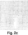
図2aおよび2eはこの画像再設定プロセスを表す。図2aおよび2bは、それぞれ息を吐くときの始めと終わりに得られる、自由に呼吸しているヒトの腹部の解剖学的画像である。図2cは、画像再設定アルゴリズムを用いて評価された二次元ベクトル場を表す。図2dは、再設定画像(図2bの画像、息を吐くときの終わりの時点)から参照画像(図2aの画像、息を吐くときの始めの時点)を取り去ることにより得られる。図2eは、再設定画像から参照画像を取り去ることにより得られる画像を表しており、これは、画像の再設定が正しく行われていることを示す。 Figures 2a and 2e represent this image resetting process. Figures 2a and 2b are anatomical images of a freely breathing human abdomen, obtained at the beginning and end of exhalation, respectively. FIG. 2c represents a two-dimensional vector field evaluated using an image reset algorithm. FIG. 2d is obtained by removing the reference image (the image of FIG. 2a, the start time when exhaling) from the reset image (the image of FIG. 2b, the end time when exhaling). FIG. 2e represents an image obtained by removing the reference image from the reset image, which indicates that the image reset has been performed correctly.
これらの異なる処理技術はしたがって、MRIイメージング2手段によって伝達されるデータから得られる画像を用いて、処理される標的領域の運動に関する多数のデータ並びに標的領域の位置の評価を決定することを可能にし得る。 These different processing techniques therefore make it possible to use the images obtained from the data transmitted by the
生物組織が医学的状況において扱われる場合、様々な移動を受ける可能性があり、処理中心点Pの位置は、最初に規定された標的領域の内部に常に位置するように、再び調整されなければならない。本発明による処理装置1のマネージングユニット5はしたがって、処理が行われている生物組織に起こり得る異なる運動を補正するために使用される。生物組織の運動、したがって、標的領域の運動は、それらの時間的発現に応じて、主として2つのカテゴリーに分類することができる。実際、例えば、筋肉が収縮する場合に生じるような偶発的運動が存在し、又、例えば、肝臓および腎臓と関する事例のような、例えば、呼吸サイクルまたは心臓サイクルと関連付けられるいわゆる周期的運動も存在する。それらが実際にはより複雑な弾性的な運動であったとしても、それらの各運動は堅固な運動(並進運動および/または回転運動の両方を含む)として見られ得ることに我々は気付くことができる。 When biological tissue is handled in a medical situation, it can undergo various movements and the position of the processing center point P must be adjusted again so that it is always located within the initially defined target area. Don't be. The managing
これらの2つのタイプの運動(偶発的または周期的)のそれぞれに対して、使用される補正ストラテジーを適合させる必要がある。 It is necessary to adapt the correction strategy used for each of these two types of movement (incidental or periodic).
実際、例えば、偶発的運動を補正するためには、利用可能な最終的解剖学的画像の時点で、計算手段を用いて、例えば、推定変位ベクトル場を使用するのが適当である。変位ベクトル場のこの推定のおかげで、処理中心点Pの位置は、その位置に関連する推定変位に従うことにより補正される。 In fact, for example, to correct for accidental motion, it is appropriate to use, for example, an estimated displacement vector field with a computing means at the time of the final anatomical image available. Thanks to this estimation of the displacement vector field, the position of the processing center point P is corrected by following the estimated displacement associated with that position.
周期的運動の特徴的な反復は、処理中心点Pの位置決定がより正確なものであるように、偶発的な運動に関して用いられる補正的な方法を適合させることを可能にする。実際、先のストラテジーは、標的領域の実際の運動が、最後に得られた画像上の推定される運動と同等であることを必要とする。この仮定により、時間間隔は、MRIイメージング手段2から生じるデータの移送とこの画像中に存在する情報の利用可能性の間で無視してよいと考えられる。MRIイメージング手段2から生じるデータの送達と処理中心点Pの位置決定における補正の間のこの待ち時間は、典型的には、取得時間、画像再構築時間、移送時間、および、標的領域の位置を調べる計算時間からなる。このタイムラグ典型的には2秒間であり、呼吸運動の周期は5秒間であり、偶発的な運動を補正するために採用されるストラテジーが、標的領域の実際の運動に対して位相的にほぼ逆である、推定される運動を生じる。結果として、この補正ストラテジーは、周期的運動を補正するために使用される場合には、処理中心点Pの位置決定エラーを倍加させる可能性がある。 The characteristic repetition of the periodic movement makes it possible to adapt the corrective method used for accidental movement so that the positioning of the processing center point P is more accurate. In fact, the previous strategy requires that the actual motion of the target region is equivalent to the estimated motion on the last obtained image. With this assumption, the time interval is considered negligible between the transfer of data originating from the MRI imaging means 2 and the availability of information present in this image. This waiting time between the delivery of data originating from the MRI imaging means 2 and the correction in determining the position of the processing center point P typically represents the acquisition time, the image reconstruction time, the transfer time and the position of the target area. It consists of calculation time to check. This time lag is typically 2 seconds, the period of the respiratory motion is 5 seconds, and the strategy employed to correct the accidental motion is approximately in phase opposite to the actual motion of the target area. Produces an estimated motion that is As a result, this correction strategy can double the processing center point P positioning error when used to correct periodic motion.
これらの理由により、補正を必要とする待ち時間を定量することにより周期的運動を補正することが必須である。補正ストラテジーは、例えば、画像中に存在する全体の優勢な運動のバリエーションの分析に基づく。 For these reasons, it is essential to correct the periodic motion by quantifying the waiting time that requires correction. The correction strategy is based, for example, on an analysis of the overall dominant motion variation present in the image.
周期的運動の補正には、後述するいくつかのステップを必要とする。 The correction of the periodic motion requires several steps described later.
処理される標的領域の優勢な運動のモデル分析をまず行うことは重要である。このモデリングステップは、標的領域の生物組織の運動が分析される間の前処理段階の間に起動されるモデリング手段を用いて行われる。呼吸サイクルにより、特に、標的領域は、特定の周期性により特徴付けられる運動に従う。呼吸サイクルは完全に規則的なものではないため、平均的周期を確立するために、前処理ステップの間に得られる平均的な数の周期が測定される。これらの周期の各々は、呼吸サイクルにおける正確なサンプリングを行うために、確立された平均的周期へと調整され得る。 It is important to first perform a model analysis of the dominant motion of the target area being processed. This modeling step is performed using modeling means that are activated during the pre-processing phase while the movement of biological tissue in the target area is analyzed. With the respiratory cycle, in particular the target area follows a movement characterized by a certain periodicity. Since the respiratory cycle is not completely regular, the average number of periods obtained during the preprocessing step is measured to establish the average period. Each of these periods can be adjusted to an established average period to provide accurate sampling in the respiratory cycle.
次いで、標的領域の優勢な運動を、以下の数式によりN桁のフーリエ級数に分解される周期的運動へと変換することができる。 The dominant motion of the target region can then be converted into a periodic motion that is decomposed into an N-digit Fourier series by the following equation:

この数式中、anおよびbnは、各調和の要素である。実際に、N=3は、平均的周期に関する効率的なモデリングのための良い値である。これより高い調和は、実際に、0.1ミリメートルを下回る幅を有する。During this equation,a n andb n are the elements of each harmonic. In fact, N = 3 is a good value for efficient modeling with respect to the average period. The higher harmonics actually have a width of less than 0.1 millimeter.
係数anおよびbnの決定は、前処理ステップの間に得られる、異なる点Kを用いた最小二乗法に基づいて行われる。 The determination of the coefficients an and bn is based on the least square method with different points K obtained during the preprocessing step.
本発明の実施形態の1つによれば、モデリング手段はさらに、処理ステップの間の標的領域の運動をモデリングすることができる。 According to one embodiment of the present invention, the modeling means can further model the movement of the target area during the processing step.
さらに、我々は、非周期的運動をモデリングすることができるモデリング手段を使用することができ、これらの運動は、偶発的な運動と比較して比較的長周期の時間に亘り特徴付けられる。 Furthermore, we can use modeling tools that can model non-periodic movements, which are characterized over a relatively long period of time compared to accidental movements.
モデリングされる標的領域の運動は、処理中心点Pの位置に関する我々の補正において、我々はより厳密であり得る。 The movement of the modeled target region can be more rigorous in our correction for the position of the processing center point P.
処理中心点Pの再配置に関する第1のステップは、例えば、標的領域の位置における情報を得るために、前述の方法でイメージング手段2の測定信号を分析することにある。 The first step relating to the rearrangement of the processing center point P consists in analyzing the measurement signal of the imaging means 2 in the manner described above, for example, in order to obtain information on the position of the target region.
MRIイメージング手段2から生成された解剖学的画像に基づいて、標的領域の空間位置をまず決定することが重要である。空間位置は、画像とおよび参照画像の間の標的領域の変位Dを分析することから生じる。 It is important to first determine the spatial position of the target region based on the anatomical image generated from the MRI imaging means 2. The spatial position arises from analyzing the displacement D of the target area between the image and the reference image.
第2のステップは、標的領域の画像に相当する時間位置を決定することにある。最後の画像のこの時間位置tiは、先に決定された空間位置の因数として決定され、結果として、平均的周期に相当するドミナントDの変位の因子である数式D=M(ti)の解を決定することにより、決定される。The second step consists in determining a time position corresponding to the image of the target area. This time position ti of the last image is determined as a factor of the previously determined spatial position and, as a result, of the formula D = M (ti ), which is a factor of the displacement of the dominant D corresponding to the average period. It is determined by determining the solution.
しかし、標的領域の運動における三角法の多項式M(t)モデリングはいくつかの根を有し、すなわち、適切な判断がなされないことは、周期期間が長くなるまたは短くなることに関する原因である。この判断の欠如が起こらないようするために、すなわち、標的領域に関し保存されている変位データを参照することが必要である。L個(例えばLを5に設定する)の最新の動態における優勢な変位と正確かつ安定した方法で得られた画像上の標的領域の位置を時間的に配置するため三角法の多項式の間のユークリッド距離を計算することができる。 However, trigonometric polynomial M (t) modeling in the motion of the target area has several roots, i.e., lack of proper judgment is a cause for longer or shorter period periods. In order to avoid this lack of judgment, it is necessary to refer to the displacement data stored for the target area. Between the triangulation polynomials to temporally position the position of the target area on the image obtained in an accurate and stable manner with the dominant displacement in the latest dynamics of L (eg set L to 5) Euclidean distance can be calculated.
ひとたび時間位置が決定されると、運動の可動化に関する標的領域位置が正確に規定される。それにもかかわらず、この評価された位置は、MRIイメージング手段2が画像を得ており、その標的領域の実際の位置は得ていない時点での標的領域の位置に相当する。実際、MRIイメージング手段2から生じたデータを移送し処理するためにかかる待ち時間中に、標的領域の運動は停止しない。位置情報が入手できた時点での標的領域の実際の位置は、調べた位置とは異なる。したがって、この待ち時間の間に起こる運動を補正することが不可欠である。 Once the time position is determined, the target area position for movement mobilization is accurately defined. Nevertheless, this evaluated position corresponds to the position of the target area at the time when the MRI imaging means 2 has obtained an image and the actual position of the target area has not been obtained. In fact, the movement of the target area does not stop during the waiting time taken to transfer and process the data generated from the MRI imaging means 2. The actual position of the target area when the position information is available is different from the examined position. It is therefore essential to compensate for the movement that occurs during this waiting time.
したがって、処理中心点Pを位置決定するために、マネージングユニット5の制御手段7は、標的領域の実際の位置を決定することができ、処理中心点Pをこの実際の位置の因数として位置決定ることができる。 Therefore, in order to determine the processing center point P, the control means 7 of the managing
第一に、制御手段は、位置を計算するために不可欠な待ち時間がそこに付加される評価された時間位置に相当する、実時間位置を決定する。 First, the control means determines a real-time position that corresponds to the estimated time position to which the waiting time essential for calculating the position is added.
ひとたび実時間位置が決定されると、相当する実空間位置を決定し、この実空間位置の因数として処理中心点Pを位置決定するために、標的領域の運動に関するモデリングが用いられる。 Once the real-time position is determined, modeling with respect to the movement of the target region is used to determine the corresponding real space position and to locate the processing center point P as a factor of this real space position.
実時間位置を決定するために、例えば、待ち時間を、前処理ステップの間に測定される待ち時間の平均的値に等しくすることにより、待ち時間が一定であると考えることができる。 In order to determine the real-time position, the latency can be considered constant, for example by making the latency equal to the average value of the latency measured during the preprocessing step.
本発明の別の実施形態によれば、処理装置1は、MRIイメージング手段2のデータを用いて標的領域の位置を調べるために不可欠な、各動態における待ち時間の値を正確に測定するために、測定手段10と共に提供される。処理装置1は、例えば、MRIイメージング手段2のデータが計算手段6により受け取られた時と評価された時間位置が決定される時の間の時間を測定するマイクロコントローラー10を含む。後述するように、かかる測定手段10の使用は、後者が、計算手段に関して必要とされる異なる計算時間に非常に依存することを前提として、待ち時間の正確な補正を可能にし、動態が変わるごとに作業能力が異なることを考慮すると、これらの計算時間は、場合により変化する。 According to another embodiment of the present invention, the
待ち時間の間の標的領域の運動の補正以外に、制御手段7は標的領域の運動を予測することができる。 Besides correcting the movement of the target area during the waiting time, the control means 7 can predict the movement of the target area.
MRIイメージング手段2による2つの連続したデータ取得の間には、実際に特定のタイムラグが存在し、したがって、標的領域の実空間位置を2連続で決定する間には、タイムラグが存在する。それにもかかわらず、例えば、マイクロコントローラー10により測定される標的領域の評価された時間位置および待ち時間に関する知見は、標的領域の優勢な運動を多項式モデリングすることで、次回のMRIデータを処理するまでの間の優勢な変位を予測することを可能にする。 There is actually a specific time lag between two consecutive data acquisitions by the MRI imaging means 2, and therefore there is a time lag between determining two real space positions of the target region in succession. Nevertheless, for example, knowledge of the estimated time position and latency of the target area measured by the
標的領域の実空間位置を最後に決定してから、「予測時間」と称される一定の時間が経過しているという事実にも関わらず、標的領域内の処理中心点Pを再配置しようと試みる場合には、予測時間位置における標的領域の運動のモデリングに相当する、予測空間位置を決定することで十分であり、この予測時間位置は、待ち時間および予測時間により強化された、最後に評価された時間位置に等しい。 In spite of the fact that a certain time called “prediction time” has elapsed since the real space position of the target area was last determined, the processing center point P in the target area is to be rearranged. When trying, it is sufficient to determine the predicted spatial position, which corresponds to the modeling of the motion of the target region at the predicted time position, and this predicted time position is finally evaluated by latency and predicted time. Equal to the time position.
可能な限り、処理中心点を再配置するために、いくつかの予測を選択することが好ましい。好ましくは、制御手段は、新たに評価された時間位置が計算手段6に関し決定されるまでの予測を用いて処理中心点Pを再配置するものとする。 It is preferable to select several predictions to relocate the processing center points whenever possible. Preferably, the control means rearranges the processing center point P using a prediction until a newly evaluated time position is determined with respect to the calculation means 6.
全ての場面で、計算手段6の性能によって待ち時間がわずかである場合には、例えばそれを無視することができるということが留意されねばならない。この場合、制御手段7は、ラグのみの予測を考慮に入れて(待ち時間はゼロと考えられる)、処理中心点Pを位置決定することにより、標的領域の運動を補正するものとする。 It should be noted that in all cases, if the waiting time is small due to the performance of the calculation means 6, it can be ignored, for example. In this case, the control means 7 shall correct the motion of the target area by taking into account the prediction of only the lag (the waiting time is considered to be zero) and locating the processing center point P.
剛性であって弾性がないと考えられている組織の運動に関しては、全体的な優勢な運動に関する知見は、全体的な対象の変位場を決定するために十分であり、その優勢な運動のモデリングも同様に十分である。 For tissue motions that are considered rigid and inelastic, knowledge of the overall dominant motion is sufficient to determine the displacement field of the overall object, and modeling that dominant motion Is equally sufficient.
一方、伸縮運動等のより複雑な組織の運動に関しては、運動マップを作成するものとする。このマップは、医療処置の前に行われた前処理ステップの間に評価された変位場(図2c中に存在する)で保存された記憶を含む。その処理の間に、そのマップは、その局部的に関連する変位場を推定するために最も近い、全体的な優勢な運動を探索する。それは、位置の調査が行われる変位場に基づく。 On the other hand, a motion map is created for more complicated tissue motion such as stretching motion. This map includes storage saved with displacement fields (present in FIG. 2c) evaluated during preprocessing steps performed prior to the medical procedure. During that process, the map searches for the closest overall dominant motion to estimate its locally relevant displacement field. It is based on the displacement field where the position is investigated.
さらに、システムの安定性を増加させるためには、待ち時間を最大限に低減することが重要である。これを行うため、標的領域の優勢な運動を規定するために、標的領域のリアルタイムの測定信号を送達する別の測定手段(例えば、ナビゲータ・エコーまたは超音波エコー等)を用いてもよい。この優勢な運動は、変位場がRMI画像から作成されるマップから得られる場合に、剛性の運動を補正し、または選択を可能にするために直接的に用いることができる。 Furthermore, it is important to reduce the waiting time to the maximum in order to increase the stability of the system. To do this, another measurement means (eg navigator echo or ultrasound echo) that delivers real-time measurement signals of the target area may be used to define the dominant movement of the target area. This dominant motion can be used directly to correct for rigid motion or allow selection if the displacement field is obtained from a map created from RMI images.
標的領域のリアルタイムの測定信号により、優れた時間解像度を有する運動の評価が獲得され、RMI測定信号は運動の正確な空間評価を提供し、標的領域の異なる測定信号を組み合わせて、各運動測定ツールの空間的および時間的な優位点を利用したアプローチを提供する。 The real-time measurement signal of the target area gives an evaluation of the movement with excellent temporal resolution, the RMI measurement signal provides an accurate spatial evaluation of the movement, and the different measurement signals of the target area can be combined into each movement measurement tool Provides an approach that takes advantage of the spatial and temporal advantages of.
本発明の別の実施形態によれば、処理装置のMRIイメージング手段2は、標的領域の解剖学的画像データを提供することができるだけでなく、標的領域の熱画像データを提供するように設計することもできる。かかる熱画像は、標的領域の温度の空間分布を示すことを可能にする。 According to another embodiment of the present invention, the MRI imaging means 2 of the processing device is designed not only to provide anatomical image data of the target area, but also to provide thermal image data of the target area. You can also. Such a thermal image makes it possible to show the spatial distribution of the temperature of the target area.
核磁気共鳴イメージングは、実際、体内の水分子中に含まれるプロトンの磁気的な特性を検出することに基づく。核磁気共鳴により画像を構築するシステムは、調べられる領域の各容積単位(voxel)は複素数Meifと関係し、Mは分子であり、fは巨視的磁性におけるベクトルの位相である。要素Mは、解剖学に関する情報を提供し、いわゆる解剖学的画像の構築を可能にする。MRIに導かれる温度測定の原理は、温度マッピングを計算するためのコントラスト変化を分析することにより動力学的画像取得を行うことに基づく。動力学的温度測定を、特に、より値の高いところで(1.5テスラ)行うために最も通常的な方法は、様々な時間において得た位相画像のコントラストを比較することである。(運動のアーチファクトまたはその余地がない)特定の十分に規定された条件下では、2つの連続的な画像間の位相における差異は、温度差に直接的に比例する。Nuclear magnetic resonance imaging is actually based on detecting the magnetic properties of protons contained in water molecules in the body. In a system that constructs an image by nuclear magnetic resonance, each volume unit (voxel) of the region being examined is associated with a complex number Meif , M is a molecule, and f is the phase of a vector in macroscopic magnetism. Element M provides information about the anatomy and allows the construction of so-called anatomical images. The principle of temperature measurement guided by MRI is based on performing kinetic image acquisition by analyzing the contrast change to calculate the temperature mapping. The most common way to make kinetic temperature measurements, especially at higher values (1.5 Tesla), is to compare the contrast of the phase images obtained at different times. Under certain well-defined conditions (without motion artifacts or room for it), the difference in phase between two successive images is directly proportional to the temperature difference.
式中、ΔTは温度差、γは磁気回転比(γ≒42,58.2πMHz/T)、α 温度係数(=0.01ppm/K)、TE エコー遅延、B0 磁石の磁気誘導である。この計算は、温度マップを得るために、各画像の画素に関して行われる。Wherein, [Delta] T is the temperature difference, gamma is the gyromagnetic ratio (γ ≒ 42,58.2πMHz / T), α the temperature coefficient(= 0.01ppm / K), T E echo delay is the magnetic inductionB 0 magnet . This calculation is performed on the pixels of each image to obtain a temperature map.
標的領域の温度測定に関するこのモニタリングにより、次いで、処理される生物組織の壊死の程度を調べるために、熱量を決定することが可能になる。 This monitoring of the target area temperature measurement then makes it possible to determine the amount of heat in order to examine the degree of necrosis of the biological tissue being processed.
それにもかかわらず、温度測定のこのモニタリング方法は、生物組織の標的領域における可能性ある運動に対し感受性である。したがって、温度変化を正確にモニタリングするためには、偶発的なものであるか、または周期的なものである、標的領域の様々な運動によって生じる温度測定のアーチファクトを補正することが不可欠である Nevertheless, this monitoring method of temperature measurement is sensitive to possible movements in the target area of biological tissue. Therefore, in order to accurately monitor temperature changes, it is essential to correct for temperature measurement artifacts caused by various movements of the target area, which are accidental or periodic
実際、運動がtn−1とtnの間で偶発的に生じる場合、この偶発的な運動に続いて計算された温度マップは正確ではない。単純な方法は、tn(fn)の時点で得られた位相画像を新たな参照位相画像とすることにある。i>nである時間tiにおける温度マップは、以下の数式により計算される。In fact, if the motion occurs accidentally between tn-1 and tn , the temperature map calculated following this accidental motion is not accurate. A simple method is to use the phase image obtained at time tn (fn ) as a new reference phase image. The temperature map at time ti where i> n is calculated by the following mathematical formula.
式中、DT’は、運動に対する補正後の温度のn−1マップである。 Where DT 'is an n-1 map of the corrected temperature for motion.
周期的運動により生じた温度アーチファクトを補正するために、医療処置の前に行われる前処理ステップにおける運動の因数としての温度画像の妨害を分析することが可能である。運動マップは、医療処置として同様の順序を含むが、その間に発熱療法が用いられない前処理ステップの間に得られた画像から構築される。例えば、50画像の取得により、正確な呼吸サイクルのサンプリングが可能になる。選択される参照位相画像は、時間的に連続したもののうち最初のものである。前処理ステップの間、解剖学的画像 は、相当する位相画像と共にマップ中に保存される。医療処置の間、現在の解剖学的画像 は、マップ中に保存されている解剖学的画像と比較される。最も類似するマップ中の画像が選択され、相当する位相画像が温度計算の参照として選択される。次いで、解剖学的画像並びに温度画像中の療法で補正を行うために、臓器における変位が解剖学的画像上で推定される。 In order to correct for temperature artifacts caused by periodic motion, it is possible to analyze the disturbance of the temperature image as a factor of motion in a pre-processing step performed before the medical procedure. The motion map is constructed from images obtained during a pre-processing step that includes a similar sequence as a medical procedure, but during which no fever therapy is used. For example, acquisition of 50 images allows for accurate respiratory cycle sampling. The selected reference phase image is the first of the temporally continuous images. During the preprocessing step, the anatomical image is saved in the map along with the corresponding phase image. During the medical procedure, the current anatomical image is compared with the anatomical image stored in the map. The most similar image in the map is selected and the corresponding phase image is selected as a reference for temperature calculation. The displacement in the organ is then estimated on the anatomical image for correction with the therapy in the anatomical image as well as the temperature image.
さらに、温度変化のモニタリングおよびすなわち標的領域に対する熱量モニタリングが正確に行われる場合、すなわち、標的領域の様々な運動により引き起こされる温度アーチファクトに対する補正によって、処理装置1の中核をなす、標的領域の処理中心点Pに対し照射される放射の調節手段を予測することができる。 Furthermore, if the temperature change monitoring and the heat quantity monitoring for the target area are performed accurately, i.e. by correcting for temperature artifacts caused by various movements of the target area, the processing center of the target area is the core of the processing device 1 A means for adjusting the radiation emitted to the point P can be predicted.
MRIイメージング手段2から生じる熱画像は、標的領域にかかる熱量にしたがって生じ、標的領域内の温度の空間分布が、温度の空間分布に関する制御信号に関連するように、処理中心点Pでの標的領域の放射を調節することは価値があり得る。 The thermal image generated from the MRI imaging means 2 is generated according to the amount of heat applied to the target area, and the target area at the processing center point P is such that the spatial distribution of temperature in the target area is related to a control signal relating to the spatial distribution of temperature It can be worth adjusting the radiation.
温度画像から生じる温度測定値情報は、標的領域の温度の正確な制御を可能にし、生物組織の標的領域に関して所望の温度を確保することを可能にするために、調節手段を用いて調節することができる。 The temperature measurement information resulting from the temperature image can be adjusted using adjustment means to allow precise control of the temperature of the target area and to ensure the desired temperature with respect to the target area of the biological tissue. Can do.
標的領域がスポット的な手順で処理され得る場合、温度は、比例・積分・微分自動制御(PID)を用いて、MRI温度画像から調整することができる。この技術は、温度ξの誤差要因を最小化するPID項を含む微分方程式(数5)に基づく。 If the target area can be processed in a spot-like procedure, the temperature can be adjusted from the MRI temperature image using proportional-integral-derivative automatic control (PID). This technique is based on a differential equation (Equation 5) that includes a PID term that minimizes the error factor of temperature ξ.
ξパラメーターは、標的領域の温度θと測定される温度Tの間の差を表す。 The ξ parameter represents the difference between the temperature θ of the target area and the measured temperature T.
比例的な項は、測定された温度と標的領域温度の瞬間的な誤差と等しい。積分的な項は、誤差の合計および過去の温度により規定される。派生する項は、所望の温度を得るために温度において存在するバリエーションにより決定される。 The proportional term is equal to the instantaneous error between the measured temperature and the target area temperature. The integral term is defined by the total error and the past temperature. The derived term is determined by the variations present in the temperature to obtain the desired temperature.
パラメーターは、操作者により定義され、PID制御での3つの項の相対的な重要性に影響を及ぼす。この自動制御は、標的領域の温度に対する安定的な収束を確実にする。 Parameters are defined by the operator and affect the relative importance of the three terms in PID control. This automatic control ensures a stable convergence with respect to the temperature of the target area.
PID制御はさらに、生物組織の反応を予測するために、温度移送の数式(数6)と組み合わされる。この数式は、温度の核酸および組織による超音波の吸収を考慮する。 PID control is further combined with a temperature transfer equation (Equation 6) to predict biological tissue response. This formula takes into account the absorption of ultrasound by temperature nucleic acids and tissues.
PIDの微分方程式は、その指数が式(数7)により規定される値ごとに選択されるとき、温度に由来する項を正しく調整するために、尊重される。 The PID differential equation is respected in order to correctly adjust the term derived from temperature when its exponent is selected for each value defined by equation (Equation 7).
可動性の組織の決定された点での温度を制御するために、中央の参照位置を再設定する補正された温度マップを用いて、PIDフィードバック制御アルゴリズムが計算される。この温度マップを用いて、温度制御に必要とされる指数に関する計算の全てが、静止した生物組織について同様になされる。測定処理点または予測処理点のそれぞれの位置決定に関して、放射指数が次いで調整され得る。 In order to control the temperature at the determined point of the mobile tissue, a PID feedback control algorithm is calculated using a corrected temperature map that resets the central reference position. Using this temperature map, all calculations related to the index required for temperature control are similarly made for stationary biological tissue. For each position determination of the measurement processing point or the prediction processing point, the radiation index can then be adjusted.
わずか1ミリメートルの小さな中心点の処理を伴う、数ミリメートルを含む大容量を処理するために、ひとつの方法は、処理中心点を進路に沿って移動させることにある。温度の空間制御に関し、音響出力量は、標的領域容積における全ての点に関し、数式(数7)により規定される。しかし、処理中心点Pを移動させるために(電子的なまたは機械的な)いかなる技術が用いられても、この出力を各点で発生させ、かつ同時に規定することは技術的に困難である。この問題を回避するために、点rにおいて時間tFのフィードバック制御サイクルの間に移送されるエネルギー量Eが、数式(数8)により定義される。 To handle large volumes, including a few millimeters, with a small center point processing of only 1 millimeter, one method is to move the processing center point along the path. Regarding the spatial control of temperature, the amount of sound output is defined by the equation (Equation 7) for all points in the target area volume. However, whatever technique (electronic or mechanical) is used to move the processing center point P, it is technically difficult to generate this output at each point and define it simultaneously. In order to avoid this problem, the amount of energy E transferred during the feedback control cycle at time tF at point r is defined by the equation (Equation 8).
このエネルギーは各点へと連続的に、それぞれの遅延と共に送達され、出力値は適当に選択される。セキュリティー因子を向上させるために、高レベルのエネルギーを必要とする点は、高レベルの出力を用いるよりも、長い中心周期にわたり加熱される。そのように、かかるフィードバックサイクルの遅延は、出される最大出力を制限するために必要とされるエネルギーに相当する、重み付けされた値を伴う、いくつかの長さへと分割される。温度制御の量を最適化するために、フィードバックサイクル、すなわち、動態を得る際の遅延は、可能な限り短くなるよう選択される。 This energy is delivered continuously to each point with a respective delay, and the output value is selected appropriately. Points that require a high level of energy to improve the security factor are heated over a longer central period than using a high level of power. As such, the delay of such a feedback cycle is divided into several lengths with weighted values that correspond to the energy required to limit the maximum power delivered. In order to optimize the amount of temperature control, the feedback cycle, ie the delay in obtaining kinetics, is chosen to be as short as possible.
制御手段は、計算または予測のいずれかにより、処理中心点Pが標的領域の運動を追跡するようにさせ、したがって、処理中心点Pが処理容量に関し追跡する経路を可能な限り大きくさせる経路もまた改変される。この経路を規定する各点は、制御手段を用いて本明細書中に記載されるのと同様の方法で補正される。この方法において、放射は正しく調節されてサンプリングされ、効率的な容積測定処理を有することを可能にする。 The control means causes the processing center point P to track the movement of the target region, either by calculation or prediction, and thus the path that makes the processing center point P track in terms of processing capacity as large as possible. Will be modified. Each point defining this path is corrected in the same manner as described herein using control means. In this way, the radiation is sampled correctly and makes it possible to have an efficient volumetric process.
本発明の装置を用いた運動中の生物組織の処理の評価
図3に示すように、本発明の処理装置は、人工的に可動性に作られ、MRIイメージング装置11中に置かれた、変換器12を用いた集束超音波を用いて処理して、ex−vivoのブタ筋肉に関し評価された。標的領域13は、伝達ドライブ14により遠隔移動される。シミュレートされた運動は、ドライブが手動で移動される場合は偶発的であり、モーター15により移動される場合には周期的である。モーター15の電圧を変えることにより、運動の周期性を次いで選択することが可能である。さらに、標的領域13の運動は、それが停止の前に置かれたスライドするまたは弾性を有するガイド上に置かれる場合、剛性であり得る。Evaluation of Processing of Biological Tissue During Exercise Using the Apparatus of the Present Invention As shown in FIG. 3, the processing apparatus of the present invention is artificially made mobile and placed in an
剛性運動である、標的領域13の平行移動を調査する場合、ドライブの位置は、ミリメートル測定ストリップ16を用いて測定される。2つの発光する光ダイオード17および2つの光受容体が、0.5mmの正確さでストリップの位置を特定する。標的領域の変位時間をマイクロ秒まで測定する20MHzのPICマイクロコントローラー18により、計測ストリップの計測がなされる。計測ストリップの位置がそれぞれ変化した後、標的領域の時間および位置が、例えば、RS232接続を用いて、数マイクロ秒のうちにモニタリングパネルへと伝達される。リアルタイムでの標的領域13の位置におけるこれらの時間測定は、MRIから生じる画像を用いて、推定変位および予測変位の質を調べるための参照としての役割を果たす。 When investigating the translation of the
処理点の補正標的領域の運動の補正に関して、処理装置の性能をまず調べることが不可欠である。MRI画像上の推定される運動(待ち時間に関する補正を行わないことを意味する)と、伝達ドライブに対し取り付けられた計測ストリップ上のマイクロコントローラーによって測定される実際の運動を伴って予測される運動(すなわち、予測される運動および待ち時間を考慮に入れて補正された運動の両方)とを比較することは、価値がある。 Correction of processing points It is essential to first check the performance of the processing device with respect to the correction of the movement of the target area. Predicted motion with estimated motion on MRI image (meaning no correction for latency) and actual motion measured by a microcontroller on a measurement strip attached to the transmission drive It is worth comparing (ie, both predicted motion and motion corrected to take into account latency).
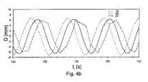
第一の技術は、運動の周期性が手順を通じて完全に一定であることを支持することにある。前処理ステップの優勢な予測変位における3次からなる多項式が、運動を補正するために用いられる。この多項式は、初期動態における実際の運動とよく一致する。それでもなお、下方のモーターの角速度における1%の偏差にもかかわらず、再更新されない多項式関数に対してモデリングされた予測される運動は、実際の運動から直ちに異なるものとなる。図4aおよび4bは、計測ストリップ上で測定される実変位(曲線19)、解剖学的画像における推定変位(曲線20)並びに一定の多項式関数に関してモデリングされた予測変位(曲線21)を示す。 The first technique is to support that the periodicity of movement is completely constant throughout the procedure. A third order polynomial in the prevailing predicted displacement of the preprocessing step is used to correct the motion. This polynomial is in good agreement with the actual motion in the initial dynamics. Nevertheless, despite the 1% deviation in the angular velocity of the lower motor, the predicted motion modeled for the polynomial function that is not re-updated is immediately different from the actual motion. Figures 4a and 4b show the actual displacement measured on the measurement strip (curve 19), the estimated displacement in the anatomical image (curve 20) and the predicted displacement modeled with respect to certain polynomial functions (curve 21).
実際の運動および予測される運動の間の標準偏差は、実験開始時には非常に小さく(0.33mm)、2分後には4.5mmまで迅速に増大する。この技術は、運動の予測を可能な限り頻繁に再更新することが不可欠であることを示す。 The standard deviation between actual and predicted motion is very small (0.33 mm) at the start of the experiment and increases rapidly to 4.5 mm after 2 minutes. This technique shows that it is essential to re-update motion predictions as often as possible.
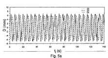
補正における別の測定によれば、待ち時間は一定であると考えられる。ex−vivoの筋肉が、本発明の実験において、振幅14mm、周期約5.6秒の周期的平行移動運動に供された。用いた試験用の台において、平均的待ち時間補正は約1.9秒である。図5aおよび5bにおいて、この測定は、計測ストリップ上で測定される実変位を表す曲線22、および、解剖学的画像上で推定変位を示す曲線23、および、一定の待ち時間の値を用いて各動態に関して再更新される、予測変位を示す曲線24を用いて説明される。 According to another measurement in the correction, the waiting time is considered constant. Ex-vivo muscles were subjected to periodic translational motion with an amplitude of 14 mm and a period of about 5.6 seconds in the experiments of the present invention. In the test bench used, the average latency correction is about 1.9 seconds. In FIGS. 5a and 5b, this measurement is made using a
測定される運動および予測される運動の間で測定される標準偏差は、実験開始時点の1mmと終了時点の2mmの間で揺れ動くため、この方法は先の方法よりも効率的である。 This method is more efficient than the previous method because the standard deviation measured between the measured and predicted movements swings between 1 mm at the start of the experiment and 2 mm at the end of the experiment.
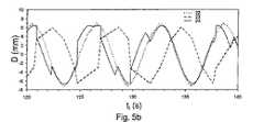
補正されるべきタイムラグは、主として、動態に関する取得の遅れ(1秒間)、および移送時間、および0.3秒間〜1.1秒間(平均0.9秒間)の間で変化する計算時間からなる。情報処理時間におけるこのぶれは、部分的には、実際の時間システムではない操作システムの使用に関連している。移送時間におけるこのぶれは、予測される運動に影響を及ぼす、推定される運動の時間的な配置における妨害を誘導する。そのようなものとして、予測される運動は、連続的で継ぎ目のない三角法曲線からなる。 The time lag to be corrected mainly consists of acquisition delay with respect to dynamics (1 second) and transfer time and calculation time varying between 0.3 seconds and 1.1 seconds (average 0.9 seconds). This shake in information processing time is in part related to the use of an operating system that is not an actual time system. This fluctuation in transfer time induces disturbances in the temporal placement of the estimated motion that affects the predicted motion. As such, the predicted motion consists of continuous, seamless trigonometric curves.
補正における別の測定によれば、待ち時間は、マイクロコントローラーを用いて、最後に時間測定された動態の開始時間と、処理の終わりの時間を比較することにより得られる.上記に類似して、ex−vivoの筋肉が、振幅14mm、周期約5.6秒の周期的平行移動運動に供された。この測定を説明する図6aおよび6bにおいて、曲線25は計測ストリップ上で測定される実変位を表し、一方、曲線26は、および、解剖学的画像上で推定変位を示し、および、曲線27は、測定された待ち時間の値を用いて各動態に関して再更新される、予測変位を示す。 According to another measurement in the correction, the waiting time is obtained by using a microcontroller to compare the last timed kinetic start time with the end time of the process. Similar to the above, ex-vivo muscles were subjected to periodic translational motion with an amplitude of 14 mm and a period of about 5.6 seconds. In FIGS. 6a and 6b illustrating this measurement, curve 25 represents the actual displacement measured on the measurement strip, while
測定される運動と予測される運動の間で測定される標準偏差は0.33mmであるため、この方法は非常に効率的である。予測される運動は、運動の周期性を調節する、微小な切れ目を除けば、連続的である。 This method is very efficient because the standard deviation measured between measured and predicted motion is 0.33 mm. The predicted motion is continuous, except for a small break that regulates the periodicity of the motion.
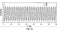
上記に示されるように、弾性運動を補正するためには、優勢な変位はもはや十分ではない。それでもなお、それは、マップから適当なベクトル場を選択する基準として用いられるものとする。図7aおよび7bは、各動態に関し測定される待ち時間を用いて、先に評価された平行移動運動に関するマップを参照する技術を用いて得られる、予測される運動を示す。曲線28は、計測ストリップ上で測定される実変位を表す。曲線29は、解剖学的画像上で推定変位を示し、曲線30は予測変位を示す。 As indicated above, the dominant displacement is no longer sufficient to correct the elastic motion. Nevertheless, it shall be used as a basis for selecting an appropriate vector field from the map. FIGS. 7a and 7b show the predicted motion obtained using a technique that refers to a map for previously estimated translational motion using the latency measured for each dynamic. Curve 28 represents the actual displacement measured on the measurement strip. Curve 29 shows the estimated displacement on the anatomical image, and
予測変位は、マップ中の50のベクトル場に相当する50の値に分解される。この予測される運動の分解は、運動における判断の予測を1分おきにのみ減少させる。実際の運動と予測される運動の間の標準偏差は、優勢な運動を用いた0.33mmに代わり、0.41mmである。 The predicted displacement is decomposed into 50 values corresponding to 50 vector fields in the map. This predicted motion resolution reduces the prediction of motion decisions only every minute. The standard deviation between actual and predicted motion is 0.41 mm instead of 0.33 mm using the dominant motion.
これらの各種の調査により、補正が行われない場合に、試験後に生じ、測定される平均的な処理中心点の位置決定エラーは4.76mmであることがわかる。 These various studies show that the average processing center point positioning error that occurs and is measured after the test when no correction is made is 4.76 mm.
このエラーの理論的評価は、実際の運動をその最初の調和を用いて近似し、時間起点をシフトさせることによりなされ得る。すなわち数式は(数9)となる。A theoretical evaluation of this error can be made by approximating the actual motion with its initial harmonics and shifting the time origin. That is, the formula is (Equation9 ).
したがって、この運動により引き起こされる理論的エラーは数式(数10)となる。 Therefore, the theoretical error caused by this motion is expressed by the following equation (Equation 10).
中心点が、最後に入手できる画像の推定される運動にしたがって位置付けされる場合、実験的なエラー読み取りは平均して7.54mmである。 If the center point is located according to the estimated motion of the last available image, the experimental error reading averages 7.54 mm.
このエラーの理論的な評価は、待ち時間の補正を一定である(1.9秒間)として行うことができる。誘導される位相の差異は、数式11となる。 The theoretical evaluation of this error can be performed assuming that the latency correction is constant (1.9 seconds). The induced phase difference is given by
この位相の差異により引き起こされる理論的なエラーは、数式(数12)となる。 The theoretical error caused by this phase difference is expressed by Equation (12).
補正された待ち時間が正しく測定される場合、測定される試験エラーは0.33mmである。理論的には、予測される運動と実際の運動の間には、もはや位相の差異は存在しない。 If the corrected latency is measured correctly, the measured test error is 0.33 mm. Theoretically, there is no longer a phase difference between the predicted motion and the actual motion.
以下の表は、理論的な、および、得られる実験的な標準偏差を比較する。 The following table compares the theoretical and experimental standard deviations obtained.
予測される運動は、運動補正を行わない位置決定よりも少なくとも14倍正確に、処理中心点の位置決定予測を可能にする。 The predicted motion allows a processing center point position prediction to be at least 14 times more accurate than position determination without motion correction.
最終的に、周期的運動の補正は動態の取得の遅延よりも大きい周期を伴う運動の補正のみを目的とするということが特筆され得る。実際、Shanon−Nyquist定理により、完全な周期を再構築し得るためには、周期ごとに2つの最小の動態のサンプリングが不可欠である。示される実験において、作られる運動の周期は約5.6秒間であり、したがって、1秒あたり1動態の取得は、運動の良好な再構築を可能にした。 Finally, it can be noted that periodic motion correction is only intended to correct motion with a period greater than the delay in acquisition of dynamics. Indeed, in order to be able to reconstruct a complete period according to the Shannon-Nyquist theorem, it is essential to sample two minimum dynamics per period. In the experiment shown, the period of motion created was about 5.6 seconds, thus the acquisition of 1 kinetic per second allowed a good reconstruction of the motion.
次いで、処理点の補正に加えた温度測定アーチファクトの補正にしたがって、処理装置が、標的領域の運動による温度測定アーチファクトを補正することができる場合、その処理装置の性能を調べることが不可欠である。したがって、ex−vivoの筋肉を、加温ステップの間に、それを各種のタイプの運動に連続的に供しながら、集束超音波装置を用いて加温した。 Then, if the processing device can correct the temperature measurement artifacts due to the movement of the target area according to the correction of the temperature measurement artifact in addition to the correction of the processing point, it is essential to examine the performance of the processing device. Therefore, ex-vivo muscles were warmed using a focused ultrasound device during the warming step, while subjecting them to various types of exercise continuously.
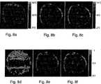
ex−vivoの筋肉は最初に、14mmの偶発的な平行移動運動に供された。その筋肉を、電力75Wを発生する超音波変換器を用いて50秒間加温した。偶発的な運動は、熱量(実験終了時点)が半分となる点で行われた。図8a〜8cは、温度測定または処理点の位置補正を行わない、温度測定補正を行うが処理点の位置補正は行わない、および、最終的に、温度測定および処理点の位置補正を行ったマップにおける温度を表す。同様に、図8d〜8fは、それぞれ、温度測定および処理点の位置補正を行わない、温度測定補正は行うが処理点の位置補正は行わない、および、最終的に、温度測定および処理点の位置補正を行った熱測定のマップを表す。 The ex-vivo muscle was first subjected to a 14 mm accidental translational movement. The muscle was warmed for 50 seconds using an ultrasonic transducer that generated 75 W of power. Accidental exercise was performed at a point where the amount of heat (at the end of the experiment) was halved. 8a-8c do not perform temperature measurement or process point position correction, perform temperature measurement correction but do not perform process point position correction, and finally perform temperature measurement and process point position correction. Represents the temperature in the map. Similarly, FIGS. 8d to 8f do not perform temperature measurement and processing point position correction, perform temperature measurement correction but do not perform processing point position correction, and finally, temperature measurement and processing point position correction, respectively. The map of the heat measurement which performed position correction is represented.
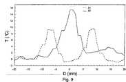
図9は、処理点の位置補正を行った場合(曲線32)、および行わない場合(曲線31)の、温度マップ上に表された中心点を通過する垂直軸に沿った温度の空間分布を示す。 FIG. 9 shows the spatial distribution of the temperature along the vertical axis passing through the center point represented on the temperature map when the position correction of the processing point is performed (curve 32) and when it is not performed (curve 31). Show.
図10は、処理点の位置補正を行った場合(曲線35)、および行わない場合(運動前の曲線33、運動後の曲線34)の、加温された領域内の温度の時間変化を示す。 FIG. 10 shows the time change of the temperature in the heated region when the position correction of the processing point is performed (curve 35) and when it is not performed (
温度測定の補正を行わずに生じる温度エラーは、40℃に到達し得る。このアーチファクトは、完全に加温プロセスを覆い隠す。同様に、計算された熱量を使用することはできない。 Temperature errors that occur without correction of temperature measurements can reach 40 ° C. This artifact completely obscures the warming process. Similarly, the calculated amount of heat cannot be used.
処理中心点の補正がなされない場合、先に加温され冷却されつつある領域および新たな標的加温領域の2つの加熱領域は同時に現れる。これらの2つの領域は、行われた運動により14mm離れて存在する。これらのいずれも、組織の壊死をもたらさない、なぜなら、局所的なエネルギーの蓄積が十分ではなかったためである。 If the processing center point is not corrected, the two heating regions of the region that has been heated and cooled first and the new target heating region appear simultaneously. These two areas are 14 mm apart due to the movements made. None of these results in tissue necrosis because the local energy accumulation was not sufficient.
処理中心点の変位が標的領域の運動を補正するとき、加温された領域のスポットが観察される。連続的な対数的な様式の温度上昇は、加温が運動により影響を受けないことを示す。同様に、円形の形態は、運動が適切に補正されたことを示す。同じ組織領域上にエネルギーが依然として潜在し、壊死が引き起こされた。 When the displacement of the processing center point corrects the movement of the target area, a spot in the heated area is observed. A continuous logarithmic mode of temperature increase indicates that warming is not affected by exercise. Similarly, the circular form indicates that the motion has been properly corrected. Energy was still latent on the same tissue area, causing necrosis.
ex−vivoの筋肉を、次いで、周期が約5.6秒間に等しい振幅14mmの周期的な平行移動運動に供した。筋肉を、電力100Wを発生する超音波変換器により1分間加温した。図11a〜11fは、温度マップ(図11a〜11c)および熱量(図11d〜11f)を、温度測定および処理中心点の位置補正を行わないもの(図11aおよび11d)、温度測定を行うが処理中心点の位置補正を行わないもの(図11bおよび11e)、並びに、最終的に温度測定および処理中心点の位置補正を行ったもの(図11cおよび11f)で比較する。 The ex-vivo muscles were then subjected to a periodic translational motion with an amplitude of 14 mm whose period was equal to approximately 5.6 seconds. The muscles were warmed for 1 minute by an ultrasonic transducer generating 100 W of power. FIGS. 11a to 11f show temperature maps (FIGS. 11a to 11c) and heat quantities (FIGS. 11d to 11f) that do not perform temperature measurement and processing center position correction (FIGS. 11a and 11d), but perform temperature measurement but process A comparison is made between those without center point position correction (FIGS. 11b and 11e) and those with temperature measurement and process center point position correction finally (FIGS. 11c and 11f).
図12は、処理点の位置補正を行ったもの(曲線37)および行わないもの(曲線36)の、温度マップ上に存在する加温された領域を通過する垂直軸(筋肉運動の軸に相当する)に沿った温度の空間分布を示す。 FIG. 12 shows a vertical axis (corresponding to an axis of muscle movement) passing through a heated region existing on the temperature map, with and without the correction of the position of the processing point (curve 37) and without (curve 36). Shows the spatial distribution of temperature along
図13は、処理点の位置補正を行ったもの(曲線39)および行わないもの(曲線38)の、試験の間に加温された領域の温度における時間変化を示す。 FIG. 13 shows the time change in the temperature of the region heated during the test, with and without the treatment point position correction (curve 39) and without (curve 38).
上記のように、温度測定の補正を行わずに生じる温度エラーは40℃に到達し得る。このアーチファクトは、行われた加温を完全に覆い隠す。同様に、計算された同じ熱量を使用することはできない。 As mentioned above, the temperature error that occurs without correcting the temperature measurement can reach 40 ° C. This artifact completely obscures the warming performed. Similarly, the same calculated amount of heat cannot be used.
中心点の補正がなされない場合、加温された領域は14mm離れて広がる。引き起こされた加温は、組織壊死をもたらさない、なぜなら、温度の上昇が不十分だからである。 If the center point is not corrected, the heated area will be 14 mm apart. The induced warming does not result in tissue necrosis because the temperature rise is insufficient.
中心点の変位が標的の運動を補正するとき、円形の加温領域は、運動が適正に補正されていることを示す。連続的な対数的な様式の温度上昇は、加温が運動により影響を受けないことを示す。組織により到達される温度は、上記の2倍高かった。同じ組織領域上にエネルギーが依然として潜在し、壊死が引き起こされた。 When the center point displacement corrects the target motion, the circular warming region indicates that the motion is properly corrected. A continuous logarithmic mode of temperature increase indicates that warming is not affected by exercise. The temperature reached by the tissue was twice as high as above. Energy was still latent on the same tissue area, causing necrosis.
最もよく多く起こる場合であり、かつ最も補正が困難である場合は、弾性周期運動の場合である。かかる変位を調べるために、vivoの筋肉を、約5.6秒間の周期性を有する周期的な押しつぶし運動に供した。筋肉を、電力100Wを発生する超音波変換器により1分間加温した。 The most frequent case and the most difficult to correct is the case of elastic periodic motion. To examine such displacement, the vivo muscles were subjected to a periodic crushing motion with a periodicity of about 5.6 seconds. The muscles were warmed for 1 minute by an ultrasonic transducer generating 100 W of power.
図14aおよび14bはそれぞれ、主要な参照画像により推定されるベクトル場の変位を伴う異なる運動位置において得られる解剖学的画像を示す。 FIGS. 14a and 14b each show anatomical images obtained at different motion positions with displacement of the vector field estimated by the main reference image.
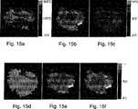
図15a〜15fは、温度マップ(図15a〜15c)および熱量(図15d〜15f)を、温度測定および処理中心点の位置補正を行わないもの(図15aおよび15d)、温度測定を行うが処理中心点の位置補正を行わないもの(図15bおよび15e)、並びに、最終的に温度測定および処理中心点の位置補正を行ったもの(図15cおよび15f)で比較する。 FIGS. 15a to 15f show temperature maps (FIGS. 15a to 15c) and calories (FIGS. 15d to 15f), which do not perform temperature measurement and processing center position correction (FIGS. 15a and 15d), perform temperature measurement but process A comparison is made between those without center point position correction (FIGS. 15b and 15e) and those with final temperature measurement and processing center position correction (FIGS. 15c and 15f).
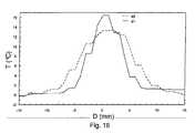
図16は、処理点の位置補正を行ったもの(曲線41)および行わないもの(曲線40)の、温度マップ上に存在する加温領域を通過する垂直軸に沿った温度における空間分布を示す。 FIG. 16 shows the spatial distribution of the temperature along the vertical axis passing through the heating region existing on the temperature map, with and without the correction (curve 41) with the processing point position corrected (curve 41). .
図17は、処理点の位置補正を行ったもの(曲線42)および行わないもの(曲線43)の、試験の間に加温された領域の温度における時間変化を示す。 FIG. 17 shows the time change in the temperature of the region heated during the test, with and without the processing point position correction (curve 42) and without (curve 43).
温度測定の補正を行わないで生じる温度エラーは、1分間で300℃に到達し得る。2πを上回る位相の変化は、2つの連続的な動態の間で見られ、経時的に蓄積する温度エラーを引き起こす。このアーチファクトは、加温を完全に覆い隠す。同様に、計算された同じ熱量を使用することはできない。 A temperature error that occurs without correcting the temperature measurement can reach 300 ° C. in one minute. A phase change of more than 2π is seen between two successive dynamics and causes a temperature error that accumulates over time. This artifact completely obscures the warming. Similarly, the same calculated amount of heat cannot be used.
中心点の補正がなされない場合、加温された領域は12mm離れて広がる。引き起こされた加温は、組織壊死をもたらさない、なぜなら、温度の上昇がそうするためには不十分だからである。 If the center point is not corrected, the heated area will be 12 mm apart. The warming caused does not result in tissue necrosis because the increase in temperature is not sufficient to do so.
中心点の変位が標的の運動を補正するとき、円形の加温領域は、運動が正確に補正されていることを示す。 When the center point displacement corrects the target motion, the circular warming region indicates that the motion is correctly corrected.
連続的な対数的な様式の温度上昇は、加温が運動により影響を受けないことを示す。組織により到達される温度は、先のものよりも高い。同じ組織領域上にエネルギーが依然として潜在し、壊死が引き起こされた。 A continuous logarithmic mode of temperature increase indicates that warming is not affected by exercise. The temperature reached by the tissue is higher than the previous one. Energy was still latent on the same tissue area, causing necrosis.
処理点の位置の補正を伴う温度の制御フィードバックここで上記に示される、変位のモニタリングを伴う熱処理装置は、組織の位置に関わらず所望の点に常に集中される一定の力を用いた収束を可能にする。さらに、温度測定の補正は、運動を行わずに得られるものと同様に良好な質の温度マップを提供する。これらの補正された温度マップは、本明細書中で上述される温度における制御フィードバックを行うことを助けることができる。このように、場所温度および空間温度の制御技術が、剛性周期運動へと供されるex−vivoの筋肉へと適用された。 Temperature control feedback with correction of the position of the treatment point The heat treatment device with displacement monitoring shown here above converges with a constant force that is always concentrated at the desired point regardless of the position of the tissue. to enable. Furthermore, the correction of the temperature measurement provides a good quality temperature map similar to that obtained without exercise. These corrected temperature maps can help provide control feedback at the temperatures described hereinabove. Thus, location and space temperature control techniques have been applied to ex-vivo muscles that are subjected to rigid periodic motion.
可動性の組織における固定化された点での温度を制御するために、運動の主要な位置で再設定され補正された温度マップを用いて、上述のスポット温度フィードバック制御アルゴリズムPIDが実行される。そのようなものとして、組織が可動性ではない場合に、温度フィードバック制御を提供するために不可欠な指数に関する全ての計算がなされる。ひとたび必要とされる指数が決定されると、中心点の位置は、上述の周期的運動の予測されるアルゴリズムを用いて、100msごとに調整される。 In order to control the temperature at the fixed point in the mobile tissue, the above-described spot temperature feedback control algorithm PID is executed using a temperature map reset and corrected at the main position of motion. As such, all calculations are made for the index that is essential to provide temperature feedback control when the tissue is not mobile. Once the required index is determined, the position of the center point is adjusted every 100 ms using the periodic motion prediction algorithm described above.
図18aおよび18bは、可動性ではないex−vivoの筋肉(図18a)、および剛性周期運動に供したもの(図18b)の温度の制御を比較する。6秒間の運動周期および14mmの振幅は、50の動態における前処理ステップ上で再構築される。上記のように、各動態は、1.5×1.5×4.5mm3のボクセルを有するdin 1sを保有する。Figures 18a and 18b compare the temperature control of non-movable ex-vivo muscles (Figure 18a) and those subjected to rigid periodic motion (Figure 18b). A 6 second motion period and an amplitude of 14 mm are reconstructed on a pretreatment step at 50 kinetics. As described above, each dynamic possesses din 1s with 1.5 × 1.5 × 4.5 mm3 voxels.
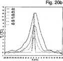
制御フィードバックを行うために選択される応答時間は8秒間である。フーリエ変換を用いて組織の挙動を予測するために用いられる組織パラメーターは、拡散係数に関して0.1mm2/sであり、吸収係数に関して0.006K/Jである。The response time selected to provide control feedback is 8 seconds. The tissue parameters used to predict tissue behavior using the Fourier transform are 0.1 mm2 / s for the diffusion coefficient and 0.006 K / J for the absorption coefficient.
組織の運動を伴うおよび伴わない両方で、160秒間〜300秒間の12℃の設定温度が、0.45℃の範囲内で達成される。使用される配列の本質的なノイズが0.3℃であるという事実を考慮して、温度測定および温度におけるフィードバック制御計算の補正は、得られる上昇温度においてノイズをほとんど引き起こさない。 A set temperature of 12 ° C. between 160 seconds and 300 seconds, with and without tissue motion, is achieved within the range of 0.45 ° C. In view of the fact that the intrinsic noise of the array used is 0.3 ° C., the correction of the temperature measurement and the feedback control calculation in temperature causes little noise in the resulting elevated temperature.
図19a〜19dは、運動を伴って(図19aおよび19c)および運動を伴わずに(図19bおよび19d)行われる2つのスポット制御フィードバックにおける、114秒の動態(図19aおよび19b)および183秒の動態(図19cおよび19d)に相当する温度マップを表す。 19a-
画像の再設定および温度測定アーチファクト補正のための技術により、運動している組織において得られた動態は、可動性でない組織上で得られたものから識別することが困難である。さらに、中心点周辺の円形の形状により示されるように、両方の場合は、等価の温度を有する。このことは、中心点が、変位に関わらず組織内部に正しく位置していることを示す。逆の場合では、加温は運動方向へ伸張する(図11b参照)。 Due to techniques for image resetting and temperature measurement artifact correction, the dynamics obtained in moving tissue are difficult to distinguish from those obtained on non-movable tissue. Furthermore, both cases have equivalent temperatures, as indicated by the circular shape around the center point. This indicates that the center point is correctly located inside the tissue regardless of the displacement. In the opposite case, the warming extends in the direction of motion (see FIG. 11b).
これら2つの試験の間での温度の空間分布を、よりよい予測と共に定量するために、図20a〜20dは、103秒(曲線46)、124秒(曲線45)および178秒(曲線44)の動態に関する、可動性でないex−vivoの筋肉上の2つの軸XおよびZに沿った(図20aのXおよび図20cのZ)温度を表し、あるいは剛性周期運動へと供される(図20bのXおよび図20dのZ)。 In order to quantify the spatial distribution of temperature between these two tests, with better predictions, FIGS. 20a-20d are 103 seconds (curve 46), 124 seconds (curve 45) and 178 seconds (curve 44). Represents the temperature along the two axes X and Z (X in FIG. 20a and Z in FIG. 20c) on the non-movable ex-vivo muscle in terms of dynamics, or subjected to rigid periodic motion (FIG. 20b) X and Z in FIG. 20d).
これらのグラフの各々において、設定温度(103秒における曲線49、124秒における曲線48、および178秒における曲線47)が予測によって尊重されることが特筆され得る。さらに、加温の幅が軸XおよびZに沿って同様であり、14mmの運動がZ軸に沿うことがわかる場合であっても、処理中心点は正しく再設定された。 It can be noted that in each of these graphs, the set temperature (
一方、運動を伴わない加温を、運動へと供された加温と比較することにより、軸XおよびZに対する温度の空間分布が約10%上昇する。この広がりは両軸上で同時に見られ、処理中心点の位置決定予測を欠いては説明できず、むしろ、処理点の電子的変位に関する二次的極大を付加することにより説明することができる。これらの二次的極大以外に、運動モニタリングを伴う温度制御は、可動性でない組織上での場合同様に、可動性の組織上でもよく機能する。 On the other hand, comparing the warming without motion with the warming applied to the motion increases the spatial distribution of temperature about axes X and Z by about 10%. This spread is seen on both axes simultaneously and cannot be explained without the prediction of the position of the processing center point, but rather can be explained by adding a secondary maximum with respect to the electronic displacement of the processing point. Besides these secondary maxima, temperature control with motion monitoring works as well on mobile tissue as it does on non-mobile tissue.
温度におけるスポットフィードバック制御の場合と同様に、可動性の組織での温度における空間フィードバック制御を行うことができる。上述のように、補正され再設定された温度マップを用いる。次いで、再設定された画像から選択されるものと中心点を一致させるために、温度空間フィードバック制御のアルゴリズムにより提供される経路が修正される。これにより、経路のそれぞれの点が、その遅延が100ミリ秒に近くなる一連の点へと、さらに分割される。これらの点のそれぞれが、次いで、その他の加温プロセスによるものと同様に、計算された運動の予測値によって変換される。この方法で、温度制御アルゴリズムにより規定される点のそれぞれにおいて降下されたエネルギーおよび中心点の位置は、良好な時間サンプリングを伴う運動にしたがって調整される。 As in the case of spot feedback control at temperature, spatial feedback control at temperature in a mobile tissue can be performed. As described above, a corrected and reset temperature map is used. The path provided by the temperature space feedback control algorithm is then modified to match the center point with that selected from the reset image. This further divides each point of the path into a series of points whose delay is close to 100 milliseconds. Each of these points is then transformed by the calculated motion predictions, as well as by other warming processes. In this way, the energy dropped at each of the points defined by the temperature control algorithm and the position of the center point are adjusted according to the motion with good time sampling.
図21aおよび21bは、可動性でない組織あるいは周期的平行移動を伴う運動の両者における、温度の空間フィードバック制御により行われる、2つの加温プロセスを比較する。中心点が垂直方向にX軸に沿って9mmの範囲で偏位し得るように、運動の振幅はZ軸に沿って8mmに低減される。この方法においては、組織が運動において極端な位置に配置している場合であっても、中心点はその中央の位置から6mmを超えて偏位することがない。ボクセルの幅は1.5mmであり、温度制御はZ軸の7つの中央のボクセル上、すなわち9mmの幅の部分で行われる。曲線52、51および50はそれぞれ、設定された温度に関するこれら7ボクセル上の温度の最低、平均、および最高の値を表す。 Figures 21a and 21b compare the two warming processes performed by spatial feedback control of temperature in both non-mobile tissue or motion with periodic translation. The amplitude of motion is reduced to 8 mm along the Z axis so that the center point can be displaced vertically in the range of 9 mm along the X axis. In this method, even if the tissue is placed at an extreme position in motion, the center point does not deviate more than 6 mm from the center position. The width of the voxel is 1.5 mm, and the temperature control is performed on the seven central voxels on the Z-axis, that is, the portion having a width of 9 mm.
温度上昇は、0.5℃の正確性を伴って、全体の制御領域を通じて設定されたレベルに従う。7つのフィードバック制御ボクセルにおける最高温度と最低温度の間の差異は、可動性でない組織に関し1.2℃であり、可動性の組織に関し1.3℃である。運動モニタリング技術を用いての、組織の変位は、温度測定に、または加温制御の正確性に、ほとんどいかなるノイズをも持ち込まない。 The temperature rise follows the level set throughout the entire control region with an accuracy of 0.5 ° C. The difference between the highest and lowest temperatures in the seven feedback control voxels is 1.2 ° C. for non-mobile tissue and 1.3 ° C. for mobile tissue. Tissue displacement using motion monitoring techniques introduces almost no noise to temperature measurements or to the accuracy of warming control.
図22a〜22dは、運動を伴って(図22aおよび22c)および運動を伴わずに(図22bおよび22d)行われるこれら2つのスポット温度フィードバック制御における、141秒(図22aおよび22b)および215秒(図22cおよび22d)の動態に相当する温度マップを表す。X軸に沿った9mmの延長された部分は、組織が垂直方向の8mmの周期的運動に供された場合であっても、非常にはっきりと識別されるように見える。加温された部分が変形されないため、中心点は運動を良好に追跡する。 Figures 22a-22d show 141 seconds (Figures 22a and 22b) and 215 seconds in these two spot temperature feedback controls performed with motion (Figures 22a and 22c) and without motion (Figures 22b and 22d). FIG. 22 represents a temperature map corresponding to the kinetics of FIGS. 22c and 22d. The 9 mm extended portion along the X-axis appears to be very clearly identified even when the tissue is subjected to a vertical 8 mm periodic motion. Since the heated part is not deformed, the center point follows the movement well.
温度の空間制御に関するより詳細な観察のために、図23a〜23dは、145秒(曲線55)、172秒(曲線54)および219秒(曲線53)の動態に関する、可動性でないex−vivoの筋肉における(図23aのXおよび図23cのZ)、あるいはまた、剛性周期運動に供した(図23bのXおよび図23dのZ)、2つの軸XおよびZに沿った温度を表す。 For a more detailed observation on the spatial control of temperature, FIGS. 23a-23d are non-movable ex-vivo kinetics for 145 seconds (curve 55), 172 seconds (curve 54) and 219 seconds (curve 53). Represents the temperature along the two axes X and Z in the muscle (X in FIG. 23a and Z in FIG. 23c) or also subjected to rigid periodic motion (X in FIG. 23b and Z in FIG. 23d).
すなわち、熱拡散効果がその影響を弱める場合、または、組織が軸Zに対し垂直方向に沿って移動する場合であっても、軸Xに沿った各動態に関し、設定された温度プラトーに相当して得られる温度上昇(145秒での曲線58、172秒での曲線57、および219秒での曲線56)が得られる。上記の通り、運動している組織に対する加温の空間分布は、非可動性の組織に対する加温と比較して、軸XおよびZに沿ってわずかに大きい。このことは、中心点がその中央の位置からさらに離れている時により大きいものである極大部分の存在によって説明することもできる。 That is, even if the thermal diffusion effect weakens the influence, or even when the tissue moves along the direction perpendicular to the axis Z, it corresponds to the set temperature plateau for each dynamic along the axis X. The resulting temperature rise (
さらに、非可動性の組織に対して行う加温のためには、中心点はZ軸にそって2分の1ボクセル移動する。この重大な結果を伴わないわずかな移動は、使用されるMRI画像の空間解像は処理ポイントの大きさと可能な限り近い明確な大きさとなる。 In addition, the center point moves one-half voxel along the Z axis for warming performed on non-movable tissue. This slight movement without significant consequences makes the spatial resolution of the MRI image used a clear size as close as possible to the size of the processing point.
読者は、説明されている主題およびその利点に関して、本発明と関連する重要な事実から逸脱することなく、多くの改変がなされることを認識し得る。結果として、この種類の改変の全てが、本発明および熱処理方法に付随する関連の処理方法にしたがう、運動している生物組織のための熱処理装置の範囲に組み入れられることが意図される。 The reader may recognize that many modifications can be made to the subject matter described and its advantages without departing from the important facts associated with the present invention. As a result, all of this type of modification is intended to be incorporated into the scope of heat treatment equipment for moving biological tissue in accordance with the present invention and related treatment methods associated with heat treatment methods.
Claims (41)
Translated fromJapanese前記計算手段(6)によって推定された前記標的領域の位置と、前記測定信号の測定と処理中心点の位置決定との間の位置決定タイムラグと、に基づいて前記標的領域の内部にある処理中心点(P)の位置を決定する制御手段(7)をさらに含むことを特徴とする熱処理装置。Using the measurement signal of the target area including the calculation means (6) for estimating the position ofthe targetregion, a heat treatment apparatusfor heat treating a target area in motion of the biological tissue,
The positionof the target area estimated by said calculating means(6), positioning time lagand the processing centeron the inside ofthe target region based on the betweenthe positioning of the measuring and processing center point of the measuring signal A heat treatment apparatus further comprising control means (7) for determining the position of the point (P).
標的領域測定手段が、前記標的領域の測定信号を得るために前記標的領域を測定するステップと、
計算手段(6)が、前記標的領域の測定に基づき前記標的領域の位置を推定するステップと、
制御手段(7)が、前記計算手段(6)によって推定された前記標的領域の位置と、前記測定信号の測定と処理中心点の位置決定との間の位置決定タイムラグと、に基づいて前記標的領域の内部にある処理中心点(P)の位置を決定するステップとを含むことを特徴とする方法。A method ofoperating a heat treatment apparatusfor heattreating a moving target regionof a biological tissue,
Target area measuring means, and measuringthe target area in order to obtain a measurement signal of the target region,
Calculating means (6)includes the steps of estimating the position of the target area based on the measurement of the target region,
Control means (7) isthe positionof the target area estimated by said calculating means(6),wherein the target on the basis ofthe position determination timelag, to betweenthe measurement and position determination of the process center of the measurement signal Determining the positionof a processing center point (P) withinthe region.
前記計算手段(6)が、前記標的領域の測定信号を処理するアルゴリズムを用いて前記標的領域の推定空間位置を決定するステップと、
前記計算手段(6)が、前記標的領域の運動のモデリングにしたがって、推定空間位置に対応する推定時間位置を決定するステップとを含むことを特徴とする、請求項28に記載の方法。The estimation of the location of the target area is
Said calculating means (6), andaway step to determine the estimated spatial position of the target area using an algorithm for processing the measurement signal of the target region,
29. Method according to claim 28, characterized in thatsaid calculating means (6) comprises the step of determining an estimated time position corresponding to an estimated spatial position according to a modeling of the movement of the target area.
前記制御手段(7)が、前記標的領域の実時間位置を決定するステップであって、前記推定時間位置に対応する実時間位置は待ち時間によって増大するステップと、
前記制御手段(7)が、前記標的領域の運動のモデリングにしたがって、実時間位置に基づいて標的領域の実時間位置を決定するステップと、
前記制御手段(7)が、実空間位置にしたがって前記処理中心点(P)の位置を決定するステップとを含むことを特徴とする、請求項29に記載の方法。The position determination of the processing center point (P) is as follows:
The control means (7) determining a real time position of the target region, wherein the real time position corresponding to the estimated time position is increased by a waiting time;
The control means (7) determining a real-time position of the target area based on a real-time position according to the modeling of the movement of the target area;
30. Method according to claim 29, characterized in that thecontrol means (7) comprises determining the position of the processing center point (P) according tothe real space position.
前記制御手段(7)が、前記標的領域の予測時間位置を決定するステップであって、前記推定時間位置に対応する予測時間位置は待ち時間および予測時間によって増大するステップと、
前記制御手段(7)が、前記標的領域の運動のモデリングにしたがって、予測時間位置に基づいて前記標的領域の予測時間位置を決定するステップと、
前記制御手段(7)が、実空間位置にしたがって前記処理中心点(P)の位置を決定するステップとを含むことを特徴とする、請求項30に記載の方法。The position determination of the processing center point (P) is as follows:
The control means (7) determining a predicted time position of the target region, wherein a predicted time position corresponding to the estimated time position is increased by a waiting time and a predicted time;
The control means (7) determining a predicted time position of the target area based on a predicted time position according to a modeling of the movement of the target area;
31. Method according to claim 30, characterized in that thecontrol means (7) comprises determining the position of the processing center point (P) according tothe real space position.
比較手段が、前記標的領域の温度変化を監視するために前記イメージング手段(2)が提供した前記位相画像と前記参照位相画像とを比較するステップとを含むことを特徴とする、請求項36に記載の方法。A step of determining a reference phase image by areference phase image determination means ;
Comparing means, characterized in that it comprises a stepof comparingthe imaging means (2) the phase image and the reference phaseimage provided to monitor the temperature change of the target area, to claim 36 The method described.
Applications Claiming Priority (3)
| Application Number | Priority Date | Filing Date | Title |
|---|---|---|---|
| FR0509885 | 2005-09-28 | ||
| FR0509885AFR2891153B1 (en) | 2005-09-28 | 2005-09-28 | DEVICE FOR THERMALLY PROCESSING BIOLOGICAL TISSUE IN MOTION |
| PCT/EP2006/065832WO2007036409A1 (en) | 2005-09-28 | 2006-08-30 | Device for heat treating moving biological tissues, and related method |
Publications (3)
| Publication Number | Publication Date |
|---|---|
| JP2009509600A JP2009509600A (en) | 2009-03-12 |
| JP2009509600A5 JP2009509600A5 (en) | 2009-08-27 |
| JP5126894B2true JP5126894B2 (en) | 2013-01-23 |
Family
ID=36282622
Family Applications (1)
| Application Number | Title | Priority Date | Filing Date |
|---|---|---|---|
| JP2008532699AExpired - Fee RelatedJP5126894B2 (en) | 2005-09-28 | 2006-08-30 | Apparatus for heat-treating moving biological tissue and related method |
Country Status (7)
| Country | Link |
|---|---|
| US (1) | US20090131782A1 (en) |
| EP (1) | EP1933729B1 (en) |
| JP (1) | JP5126894B2 (en) |
| AT (1) | ATE529055T1 (en) |
| CA (1) | CA2623887C (en) |
| FR (1) | FR2891153B1 (en) |
| WO (1) | WO2007036409A1 (en) |
Families Citing this family (13)
| Publication number | Priority date | Publication date | Assignee | Title |
|---|---|---|---|---|
| US9146289B2 (en)* | 2009-12-23 | 2015-09-29 | General Electric Company | Targeted thermal treatment of human tissue through respiratory cycles using ARMA modeling |
| CN102686278B (en)* | 2009-12-28 | 2016-01-13 | 皇家飞利浦电子股份有限公司 | Therapeutic equipment |
| EP2500741A1 (en) | 2011-03-17 | 2012-09-19 | Koninklijke Philips Electronics N.V. | Magnetic resonance measurement of ultrasound properties |
| FR2975886B1 (en)* | 2011-05-30 | 2013-06-28 | Univ Bordeaux Segalen | METHOD OF TARGETING A REGION OF INTEREST OF A BIOLOGICAL TISSUE OF A PATIENT AND ASSOCIATED DEVICE |
| US10307619B2 (en)* | 2012-02-06 | 2019-06-04 | Insightec, Ltd. | Reference-library extension during imaging of moving organs |
| US10420608B2 (en) | 2014-05-20 | 2019-09-24 | Verily Life Sciences Llc | System for laser ablation surgery |
| DE102014218924A1 (en)* | 2014-09-19 | 2016-03-24 | Siemens Aktiengesellschaft | Determining a position of an object using MRI scans |
| CN111032856A (en)* | 2017-08-07 | 2020-04-17 | 诺维信公司 | Use of FCA control based on pH |
| US10634559B2 (en)* | 2018-04-18 | 2020-04-28 | Raytheon Company | Spectrally-scanned hyperspectral electro-optical sensor for instantaneous situational awareness |
| JP6943826B2 (en) | 2018-09-28 | 2021-10-06 | 三菱パワー株式会社 | Internal state estimation method and equipment for thermal equipment |
| WO2020094226A1 (en)* | 2018-11-07 | 2020-05-14 | Brainlab Ag | Compartmentalized dynamic atlas |
| CN112947091B (en)* | 2021-03-26 | 2022-06-10 | 福州大学 | PID control-based method for optimizing heat production of magnetic nanoparticles in biological tissues |
| CN113341715A (en)* | 2021-06-04 | 2021-09-03 | 福州大学 | Proportional-integral control-based method for analyzing heat generation of diffusion magnetofluid in biological tissue |
Family Cites Families (18)
| Publication number | Priority date | Publication date | Assignee | Title |
|---|---|---|---|---|
| US5178135A (en)* | 1987-04-16 | 1993-01-12 | Olympus Optical Co., Ltd. | Therapeutical apparatus of extracorporeal type |
| JPS63260546A (en)* | 1987-04-17 | 1988-10-27 | オリンパス光学工業株式会社 | Ultrasonic treatment apparatus |
| JP3325300B2 (en)* | 1992-02-28 | 2002-09-17 | 株式会社東芝 | Ultrasound therapy equipment |
| DE69634976T2 (en)* | 1995-12-14 | 2006-04-20 | Koninklijke Philips Electronics N.V. | METHOD AND DEVICE FOR HEATING WITH ULTRASOUND, CONTROLLED BY IMAGING WITH MAGNETIC RESONANCE |
| FR2779548B1 (en)* | 1998-06-05 | 2000-11-10 | Thomson Csf | PROCESS FOR DYNAMIC MONITORING OF THE DEVELOPMENT OF DEFORMABLE MEDIA, AND FOR PREDICTION OF THEIR DEVELOPMENT |
| US6501981B1 (en)* | 1999-03-16 | 2002-12-31 | Accuray, Inc. | Apparatus and method for compensating for respiratory and patient motions during treatment |
| US6675034B2 (en)* | 2001-04-19 | 2004-01-06 | Sunnybrook And Women's Health Sciences Centre | Magnetic resonance imaging using direct, continuous real-time imaging for motion compensation |
| JP4060615B2 (en)* | 2002-03-05 | 2008-03-12 | 株式会社東芝 | Image processing apparatus and ultrasonic diagnostic apparatus |
| US7769427B2 (en)* | 2002-07-16 | 2010-08-03 | Magnetics, Inc. | Apparatus and method for catheter guidance control and imaging |
| JP4202697B2 (en)* | 2002-08-12 | 2008-12-24 | 株式会社東芝 | Ultrasonic diagnostic apparatus, ultrasonic image display apparatus, and ultrasonic image display method |
| DE10245943B4 (en)* | 2002-09-30 | 2008-06-26 | Siemens Ag | Method for generating CT images of a periodically moved organ and CT apparatus for carrying out such a method |
| US6994673B2 (en)* | 2003-01-16 | 2006-02-07 | Ge Ultrasound Israel, Ltd | Method and apparatus for quantitative myocardial assessment |
| US20060293598A1 (en)* | 2003-02-28 | 2006-12-28 | Koninklijke Philips Electronics, N.V. | Motion-tracking improvements for hifu ultrasound therapy |
| EP2386246A1 (en)* | 2003-05-21 | 2011-11-16 | Koninklijke Philips Electronics N.V. | Apparatus and method for navigating a catheter |
| DE602004030110D1 (en)* | 2003-05-21 | 2010-12-30 | Philips Intellectual Property | DEVICE FOR NAVIGATING A CATHETER |
| WO2005030330A1 (en)* | 2003-09-30 | 2005-04-07 | Koninklijke Philips Electronics, N.V. | Target tracking method and apparatus for radiation treatment planning and delivery |
| FR2869548B1 (en)* | 2004-04-29 | 2006-07-28 | Centre Nat Rech Scient Cnrse | THERMAL TREATMENT ASSEMBLY FOR BIOLOGICAL TISSUES. |
| US8095203B2 (en)* | 2004-07-23 | 2012-01-10 | Varian Medical Systems, Inc. | Data processing for real-time tracking of a target in radiation therapy |
- 2005
- 2005-09-28FRFR0509885Apatent/FR2891153B1/ennot_activeExpired - Fee Related
- 2006
- 2006-08-30WOPCT/EP2006/065832patent/WO2007036409A1/enactiveApplication Filing
- 2006-08-30ATAT06778412Tpatent/ATE529055T1/ennot_activeIP Right Cessation
- 2006-08-30EPEP06778412Apatent/EP1933729B1/ennot_activeCeased
- 2006-08-30JPJP2008532699Apatent/JP5126894B2/ennot_activeExpired - Fee Related
- 2006-08-30USUS11/992,902patent/US20090131782A1/ennot_activeAbandoned
- 2006-08-30CACA2623887Apatent/CA2623887C/ennot_activeExpired - Fee Related
Also Published As
| Publication number | Publication date |
|---|---|
| EP1933729A1 (en) | 2008-06-25 |
| EP1933729B1 (en) | 2011-10-19 |
| US20090131782A1 (en) | 2009-05-21 |
| CA2623887A1 (en) | 2007-04-05 |
| JP2009509600A (en) | 2009-03-12 |
| ATE529055T1 (en) | 2011-11-15 |
| FR2891153B1 (en) | 2008-08-22 |
| CA2623887C (en) | 2014-04-01 |
| FR2891153A1 (en) | 2007-03-30 |
| WO2007036409A1 (en) | 2007-04-05 |
Similar Documents
| Publication | Publication Date | Title |
|---|---|---|
| JP5126894B2 (en) | Apparatus for heat-treating moving biological tissue and related method | |
| US10677866B1 (en) | Systems and methods for correcting measurement artifacts in MR thermometry | |
| CN104812324B (en) | temperature distribution determining device | |
| De Senneville et al. | Real‐time adaptive methods for treatment of mobile organs by MRI‐controlled high‐intensity focused ultrasound | |
| US9541621B2 (en) | Techniques for correcting measurement artifacts in magnetic resonance thermometry | |
| US7505805B2 (en) | Self-referencing/body motion tracking non-invasive internal temperature distribution measurement method and apparatus using magnetic resonance tomographic imaging technique | |
| CN104602761B (en) | acoustic radiation force magnetic resonance imaging | |
| CN105358065B (en) | temperature distribution determining device | |
| JP3118278B2 (en) | Noninvasive Myocardial Motion Analysis by Phase Difference Magnetic Resonance Imaging of Myocardial Velocity | |
| CN109196369A (en) | Motion tracking during noninvasive laser therapy | |
| CN104244818A (en) | Reference-based motion tracking during non-invasive therapy | |
| JP2010524513A (en) | Method for optimizing wave convergence with an aberration insertion member | |
| CN115346029B (en) | Real-time navigation method and system for ultrasound transducer for transcranial ultrasound stimulation | |
| US20200069971A1 (en) | Position measurement device, treatment system including the same, and position measurement method | |
| Fuentes et al. | An inverse problem approach to recovery of in vivo nanoparticle concentrations from thermal image monitoring of MR-guided laser induced thermal therapy | |
| Kuo et al. | Fast Fourier transform combined with phase leading compensator for respiratory motion compensation system | |
| JP4270878B2 (en) | Equipment for heat treatment of biological tissue | |
| JP7487061B2 (en) | Magnetic resonance imaging apparatus and subject positioning method | |
| CN103596505A (en) | Method and apparatus for displaying thermal risk indicator | |
| US20040176680A1 (en) | Assembly for heat treatment of biological tissues | |
| De Senneville et al. | On-line mobile organ tracking for non-invasive local hyperthermia | |
| White et al. | A pre-treatment planning strategy for high-intensity focused ultrasound (HIFU) treatments | |
| Zhao | Real-time temperature imaging using ultrasonic change in backscattered energy | |
| Feng et al. | MRTI-based optimization and real-time laser surgical control for cancer treatment using fast inverse analysis techniques | |
| JP2006288848A (en) | Apparatus for diagnosing medical image |
Legal Events
| Date | Code | Title | Description |
|---|---|---|---|
| A521 | Request for written amendment filed | Free format text:JAPANESE INTERMEDIATE CODE: A523 Effective date:20090708 | |
| A621 | Written request for application examination | Free format text:JAPANESE INTERMEDIATE CODE: A621 Effective date:20090708 | |
| A977 | Report on retrieval | Free format text:JAPANESE INTERMEDIATE CODE: A971007 Effective date:20111118 | |
| A131 | Notification of reasons for refusal | Free format text:JAPANESE INTERMEDIATE CODE: A131 Effective date:20111129 | |
| A521 | Request for written amendment filed | Free format text:JAPANESE INTERMEDIATE CODE: A523 Effective date:20120228 | |
| TRDD | Decision of grant or rejection written | ||
| A01 | Written decision to grant a patent or to grant a registration (utility model) | Free format text:JAPANESE INTERMEDIATE CODE: A01 Effective date:20121002 | |
| A01 | Written decision to grant a patent or to grant a registration (utility model) | Free format text:JAPANESE INTERMEDIATE CODE: A01 | |
| A61 | First payment of annual fees (during grant procedure) | Free format text:JAPANESE INTERMEDIATE CODE: A61 Effective date:20121025 | |
| R150 | Certificate of patent or registration of utility model | Free format text:JAPANESE INTERMEDIATE CODE: R150 Ref document number:5126894 Country of ref document:JP Free format text:JAPANESE INTERMEDIATE CODE: R150 | |
| FPAY | Renewal fee payment (event date is renewal date of database) | Free format text:PAYMENT UNTIL: 20151109 Year of fee payment:3 | |
| R250 | Receipt of annual fees | Free format text:JAPANESE INTERMEDIATE CODE: R250 | |
| R250 | Receipt of annual fees | Free format text:JAPANESE INTERMEDIATE CODE: R250 | |
| R250 | Receipt of annual fees | Free format text:JAPANESE INTERMEDIATE CODE: R250 | |
| R250 | Receipt of annual fees | Free format text:JAPANESE INTERMEDIATE CODE: R250 | |
| LAPS | Cancellation because of no payment of annual fees |