JP5126682B2 - Head mounted display - Google Patents
Head mounted displayDownload PDFInfo
- Publication number
- JP5126682B2 JP5126682B2JP2008313887AJP2008313887AJP5126682B2JP 5126682 B2JP5126682 B2JP 5126682B2JP 2008313887 AJP2008313887 AJP 2008313887AJP 2008313887 AJP2008313887 AJP 2008313887AJP 5126682 B2JP5126682 B2JP 5126682B2
- Authority
- JP
- Japan
- Prior art keywords
- generation unit
- image generation
- unit
- head
- image
- Prior art date
- Legal status (The legal status is an assumption and is not a legal conclusion. Google has not performed a legal analysis and makes no representation as to the accuracy of the status listed.)
- Expired - Fee Related
Links
- 238000001514detection methodMethods0.000claimsdescription13
- 230000008878couplingEffects0.000claimsdescription10
- 238000010168coupling processMethods0.000claimsdescription10
- 238000005859coupling reactionMethods0.000claimsdescription10
- 238000000926separation methodMethods0.000claimsdescription4
- 238000013459approachMethods0.000claimsdescription3
- 210000003128headAnatomy0.000description36
- 210000005252bulbus oculiAnatomy0.000description4
- 230000006378damageEffects0.000description4
- 238000013461designMethods0.000description4
- 238000004891communicationMethods0.000description3
- 210000001508eyeAnatomy0.000description3
- 230000003287optical effectEffects0.000description3
- 230000002093peripheral effectEffects0.000description3
- 238000003825pressingMethods0.000description3
- 230000008054signal transmissionEffects0.000description3
- XEEYBQQBJWHFJM-UHFFFAOYSA-NIronChemical compound[Fe]XEEYBQQBJWHFJM-UHFFFAOYSA-N0.000description2
- 208000027418Wounds and injuryDiseases0.000description2
- 238000010586diagramMethods0.000description2
- 230000006870functionEffects0.000description2
- 208000014674injuryDiseases0.000description2
- 239000000463materialSubstances0.000description2
- 238000012545processingMethods0.000description2
- 210000001747pupilAnatomy0.000description2
- 230000005540biological transmissionEffects0.000description1
- 230000015572biosynthetic processEffects0.000description1
- 239000012141concentrateSubstances0.000description1
- 230000005674electromagnetic inductionEffects0.000description1
- 239000011521glassSubstances0.000description1
- 230000005484gravityEffects0.000description1
- 229910052742ironInorganic materials0.000description1
- 239000000696magnetic materialSubstances0.000description1
- 238000004519manufacturing processMethods0.000description1
- 238000000034methodMethods0.000description1
- 230000000149penetrating effectEffects0.000description1
- 230000002265preventionEffects0.000description1
- 238000003860storageMethods0.000description1
Images


Classifications
- G—PHYSICS
- G02—OPTICS
- G02B—OPTICAL ELEMENTS, SYSTEMS OR APPARATUS
- G02B27/00—Optical systems or apparatus not provided for by any of the groups G02B1/00 - G02B26/00, G02B30/00
- G02B27/01—Head-up displays
- G02B27/017—Head mounted
- G02B27/0176—Head mounted characterised by mechanical features
- G—PHYSICS
- G02—OPTICS
- G02B—OPTICAL ELEMENTS, SYSTEMS OR APPARATUS
- G02B27/00—Optical systems or apparatus not provided for by any of the groups G02B1/00 - G02B26/00, G02B30/00
- G02B27/01—Head-up displays
- G02B27/0149—Head-up displays characterised by mechanical features
- G02B2027/0167—Emergency system, e.g. to prevent injuries
Landscapes
- Physics & Mathematics (AREA)
- General Physics & Mathematics (AREA)
- Optics & Photonics (AREA)
Description
Translated fromJapanese本発明は、ユーザの頭部に装着して、画像を見ることができるヘッドマウントディスプレイに関するものである。 The present invention relates to a head-mounted display that can be worn on a user's head and view an image.
従来から、特許文献1や特許文献2に示されるようなヘッドマウントディスプレイが知られている。このようなヘッドマウントディスプレイ50は、図11に示されるように、ユーザの頭部に装着される頭部装着部51と、頭部装着部51の前側方に取り付けられた画像生成部52とから構成されている。図11に示される頭部装着部51は、ノーズパッド51a及びイヤーパッド51bを有し、メガネのフレーム形状をしている。画像生成部52で生成された画像光は、直接ユーザの眼球に照射されるようになっている。ユーザは、画像生成部52が生成する画像を視認すると同時に、外界を視認することができる。 Conventionally, head-mounted displays as shown in
このようなヘッドマウントディスプレイ50は、今後、生産工場の作業現場等で多用されることが想定される。例えば、画像生成部52に指示書や設計図等を表示させれば、作業者は、必要に応じて指示書や設計図等を閲覧することにより、より確実な作業を行うことができる。作業者は、紙媒体の指示書や設計図を手に取って閲覧する必要がないので、作業を中止することなく、作業をしながら、画像表示部52に表示された指示書や設計図を見ることができるので、作業性が向上するだけでなく、作業ミスを防止することが可能となる。 Such a head mounted
しかし、作業者が集中して作業を行い、顔を被作業物に近づけ過ぎると、この被作業物と画像表示部52が衝突し、画像表示部52が破損するだけでなく、ノーズパッド51a等で作業者の鼻や眼球を傷付けてしまう危険性がある。 However, if the worker concentrates on the work and brings the face too close to the work piece, the work piece and the
そこで、特許文献3に示されるように、頭部装着部と画像生成部との間に弾性部材を設けたヘッドマウントディスプレイが提案されている。しかしながら、被作業物と画像表示部が衝突した際の衝撃を、前記弾性部材が吸収することにより低減するはできるが、ユーザが怪我をする可能性及び、画像表示部が破損する可能性を完全に排除することができなかった。 Therefore, as shown in Patent Document 3, a head mounted display in which an elastic member is provided between the head mounting portion and the image generating portion has been proposed. However, although the impact when the work piece collides with the image display unit can be reduced by absorbing the elastic member, the possibility that the user may be injured and the image display unit may be damaged completely. Could not be eliminated.
本発明は、上記問題を解決し、ユーザの怪我及び画像表示部の破損を防止することができるヘッドマウントディスプレイを提供するためになされたものである。 The present invention has been made to provide a head-mounted display that can solve the above-described problems and prevent injury to the user and damage to the image display unit.
上記課題を解決するためになされた請求項1に記載の発明は、ユーザの頭部に装着される頭部装着部と、
前記頭部装着部の前側方に取り付けられ、前記ユーザに画像を視認させる画像生成部を有するヘッドマウントディスプレイにおいて、
障害物が前記画像生成部に近接又は接触した際に、前記画像生成部を前記頭部装着部から脱落させる脱落手段を設けたことを特徴とする。The invention according to
In the head mounted display having an image generation unit attached to the front side of the head mounting unit and allowing the user to visually recognize an image,
A drop-off means is provided for dropping the image generation unit from the head-mounted unit when an obstacle approaches or contacts the image generation unit.
請求項2に記載の脱落手段は、請求項1に記載の発明において、
頭部装着部に設けられた取付部材と、
常時は画像生成部を前記取付部材に結合させているが、作動力が付与されると、画像生成部と前記取付部材との結合を解除するロック手段と、
電力が投入された際に、前記ロック手段に作動力を付与する作動力付与手段と、
障害物の画像生成部への近接を検知する近接検知手段と、
前記近接検知手段が障害物の画像生成部への近接を検知した際に、前記作動力付与手段に電力を投入する電力入力手段とから構成されることを特徴とする。The drop-off means according to
A mounting member provided in the head mounting portion;
Normally, the image generating unit is coupled to the mounting member, but when an actuation force is applied, a lock unit that releases the coupling between the image generating unit and the mounting member;
An operating force applying means for applying an operating force to the locking means when electric power is applied;
Proximity detection means for detecting the proximity of the obstacle to the image generation unit;
When the proximity detection unit detects the proximity of the obstacle to the image generation unit, the proximity detection unit includes a power input unit that supplies power to the operating force application unit.
請求項3に記載の脱落手段は、請求項1に記載の発明において、
頭部装着部に設けられた取付部材と、
前記取付部材及び画像生成部の一方に取り付けられた磁性部材と、
前記取付部材及び画像生成部の他方に取り付けられ、前記磁性部材と磁力により結合させるマグネットと、
電力が投入された際に、前記磁性部材と前記マグネットとを離間させることにより、磁力による結合を解除させる離間手段と、
障害物の画像生成部への近接を検知する近接検知手段と、
障害物の画像生成部への近接を検知した際に、前記離間手段に電力を投入するリリースドライバとから構成されることを特徴とする。The drop-off means according to claim 3 is the invention according to
A mounting member provided in the head mounting portion;
A magnetic member attached to one of the attachment member and the image generator;
A magnet attached to the other of the attachment member and the image generation unit, and coupled to the magnetic member by a magnetic force;
Separating means for releasing the coupling by magnetic force by separating the magnetic member and the magnet when power is applied;
Proximity detection means for detecting the proximity of the obstacle to the image generation unit;
It is characterized by comprising a release driver for supplying power to the separating means when the proximity of the obstacle to the image generation unit is detected.
請求項4に記載の脱落手段は、請求項1に記載の発明において、
頭部装着部に設けられた取付部材と、
前記取付部材及び画像生成部の一方に突設され、その途中部分に係合凹部を有する係合突起と、
前記取付部材及び画像生成部の他方に凹陥形成され、前記係合手段が侵入する係合穴と、
前記係合侵入穴の両側方から、前記係合穴内に突出するようにスライド自在に配設され、その先端が前記係合突起の係合凹部に係合することで、前記係合突起を挟持する一対の挟持部材と、
前記一対の挟持部材を、互いに近接させる方向に付勢する付勢部材とから構成されることを特徴とする。The drop-off means according to claim 4 is the invention according to
A mounting member provided in the head mounting portion;
An engagement protrusion that protrudes from one of the attachment member and the image generation unit and has an engagement recess in the middle of the attachment member;
An engagement hole formed in a recess in the other of the attachment member and the image generation unit, and into which the engagement means enters,
It is slidably disposed so as to protrude into the engagement hole from both sides of the engagement entry hole, and the tip of the engagement protrusion engages with the engagement recess of the engagement protrusion, thereby holding the engagement protrusion. A pair of clamping members that
The pair of sandwiching members is constituted by a biasing member that biases the pair of sandwiching members in a direction in which the pair of clamping members are brought close to each other.
上記課題を解決するためになされた請求項1に記載の発明は、障害物が前記画像生成部に近接又は接触した際に、前記画像生成部を前記頭部装着部から脱落させる脱落手段を設けたことを特徴とする。
このため、障害物が前記画像生成部に近接又は接触した際に、画像生成部が、頭部装着部から脱落するので、画像表示部の破損や、作業者の怪我を防止することが可能となる。In order to solve the above-mentioned problem, the invention according to
For this reason, when the obstacle comes close to or comes into contact with the image generation unit, the image generation unit falls out of the head-mounted unit, so that it is possible to prevent damage to the image display unit and injury to the operator. Become.
請求項2に記載の脱落手段は、請求項1に記載の発明において、頭部装着部に設けられた取付部材と、常時は画像生成部を前記取付部材に結合させているが、作動力が付与されると、画像生成部と前記取付部材との結合を解除するロック手段と、電力が投入された際に、前記ロック手段に作動力を付与する作動力付与手段と、障害物の画像生成部への近接を検知する近接検知手段と、前記近接検知手段が障害物の画像生成部への近接を検知した際に、前記作動力付与手段に電力を投入する電力入力手段とから構成したことを特徴とする。
このため、障害物が前記画像生成部に接触する前に、確実に、前記画像生成部を前記頭部装着部から脱落させる脱落手段を実現することが可能となる。According to a second aspect of the present invention, in the invention according to the first aspect, the drop-off means connects the mounting member provided on the head mounting portion and the image generating portion to the mounting member at all times. When applied, a lock unit that releases the coupling between the image generation unit and the mounting member, an operation force application unit that applies an operation force to the lock unit when power is applied, and an image generation of an obstacle Proximity detecting means for detecting proximity to a part, and power input means for supplying power to the operating force applying means when the proximity detecting means detects the proximity of an obstacle to the image generating part. It is characterized by.
For this reason, it is possible to realize a drop-off means for reliably dropping the image generation unit from the head mounting unit before an obstacle comes into contact with the image generation unit.
請求項3に記載の脱落手段は、請求項1に記載の発明において、頭部装着部に設けられた取付部材と、前記取付部材及び画像生成部の一方に取り付けられた磁性部材と、前記取付部材及び画像生成部の他方に取り付けられ、前記磁性部材と磁力により結合させるマグネットと、電力が投入された際に、前記磁性部材と前記マグネットを離間させることにより、磁力による結合を解除させる離間手段と、障害物の画像生成部への近接を検知する近接検知手段と、障害物の画像生成部への近接を検知した際に、前記離間手段に電力を投入するリリースドライバとから構成したことを特徴とする。
このため、障害物が前記画像生成部に接触する前に、確実に、前記画像生成部を前記頭部装着部から脱落させる脱落手段を実現することが可能となる。According to a third aspect of the present invention, in the invention according to the first aspect, the drop-off means includes an attachment member provided in the head mounting portion, a magnetic member attached to one of the attachment member and the image generation portion, and the attachment. A magnet that is attached to the other of the member and the image generation unit and that is coupled to the magnetic member by magnetic force, and a separation unit that releases the coupling by magnetic force by separating the magnetic member and the magnet when power is applied. And a proximity detection means for detecting the proximity of the obstacle to the image generation unit, and a release driver for supplying power to the separation means when the proximity of the obstacle to the image generation unit is detected. Features.
For this reason, it is possible to realize a drop-off means for reliably dropping the image generation unit from the head mounting unit before an obstacle comes into contact with the image generation unit.
請求項4に記載の脱落手段は、請求項1に記載の発明において、頭部装着部に設けられた取付部材と、前記取付部材及び画像生成部の一方に突設され、その途中部分に係合凹部を有する係合突起と、前記取付部材及び画像生成部の他方に凹陥形成され、前記係合手段が侵入する係合穴と、前記係合侵入穴の両側方から、前記係合穴内に突出するようにスライド自在に配設され、その先端が前記係合突起の係合凹部に係合することで、前記係合突起を挟持する一対の挟持部材と、前記一対の挟持部材を、互いに近接させる方向に付勢する付勢部材とから構成したことを特徴とする。
このため、電子・電気部品を使用することなく、機械的な構造のみで、脱落手段を実現することができ、過大にコストアップにならずに、脱落手段を備えたヘッドマウントディスプレイを提供することが可能となる。According to a fourth aspect of the present invention, in the first aspect of the present invention, the drop-off means is protruded from one of the attachment member provided in the head mounting portion and the attachment member and the image generation portion, and is engaged in the middle portion thereof. An engagement protrusion having a concavity, a recess formed in the other of the attachment member and the image generation unit, the engagement hole into which the engagement means enters, and from both sides of the engagement entry hole into the engagement hole A pair of sandwiching members that sandwich the engaging projection and the pair of sandwiching members are arranged with each other by being slidably disposed so as to project and having a tip engaged with the engaging recess of the engaging projection. It is characterized by comprising an urging member that urges in the direction of approaching.
For this reason, it is possible to realize a drop-off means with only a mechanical structure without using electronic / electrical parts, and to provide a head mounted display equipped with a drop-off means without excessively increasing the cost. Is possible.
(ヘッドマウントディスプレイの構造)
以下に、図面を参照しつつ本発明の好ましい実施の形態を示す。図1は本発明のヘッドマウントディスプレイ本体10の全体図である。ヘッドマウントディスプレイ100(図2に示す)は、ヘッドマウントディスプレイ本体10と制御部40とから構成されている。ヘッドマウントディスプレイ本体10は、ユーザの頭部に装着される頭部装着部1と、ユーザに画像を視認させる画像生成部2とから構成されている。図1に示される頭部装着部1は、眼鏡のフレーム形状をしていて、フロントフレーム1a、テンプル1b、ノーズパッド1c、イヤーパッド1dとから構成されている。フロントフレーム1aの中央部には、ノーズパッド1cが取り付けられている。フロントフレーム1aの両端には、テンプル1bが、フロントフレーム1aに対して略垂直の状態から内側に折り畳めるように、回動自在に取り付けられている。(Head-mounted display structure)
Hereinafter, preferred embodiments of the present invention will be described with reference to the drawings. FIG. 1 is an overall view of a head mounted display
制御部40は、ユーザの腰等のユーザの身体に取り付けられるようになっている。制御部40と画像生成部2とはケーブル8で接続している。なお、ケーブル8内には、画像・制御信号伝送線8aが配設されている。 The
頭部装着部1の前側方には、取付部材3を介して、画像生成部2が取り付けられている。図1に示された実施形態では、取付部材3は、テンプル1bの前端に固着しているが、フロントフレーム1aの、テンプル1bに隣接する端部に固着している構造であっても差し支えない。画像生成部2の前端には、障害物の画像生成部2への近接を、非接触で検知する近接検知手段として作用する近接センサー4が設けられている。近接センサー4には、電磁誘導を利用した高周波発信型、磁石を用いた磁気型、静電容量の変化を利用した静電気容量型、赤外線の反射光をセンシングする赤外線検知型、超音波の反射波を検知する超音波検知型等の近接センサーが含まれる。 An
画像生成部2の後端からケーブル8が、延出している。テンプル1bには、線材支持部材9が取り付けられている。線材支持部材9には、支持穴9aが連通形成されている。ケーブル8は、線材支持部材9の支持穴9aを挿通し、線材支持部材9で支持されている。イヤーパッド1dには、線材支持部1fが形成され、当該線材支持部1fで、ケーブル8を支持している。 A
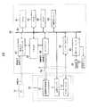
図2は本発明のヘッドマウントディスプレイ100のブロック図である。画像生成部2は、制御部40を有している。制御部40は、CPU41、RAM42、ROM43、不揮発性メモリー44、周辺インターフェース46、画像入力インターフェース47、VRAM48、コントローラ49、リリースドライバ65を有していて、これらは相互にバス55で接続されている。また、近接センサー4も、バス55に接続している。 FIG. 2 is a block diagram of the head mounted
CPU(Central ProceSSing Unitの略)41は、RAM(Random AcceSS Memoryの略)42、ROM(Read Only Memoryの略)43と協動して、各種演算、処理を行うものである。 A CPU (abbreviation of Central ProcessSSing Unit) 41 performs various calculations and processes in cooperation with a RAM (abbreviation of Random AccessSS Memory) 42 and a ROM (abbreviation of Read Only Memory) 43.
RAM42は、CPU41によって処理されるプログラムや、CPU41で処理するデータを、そのアドレス空間に一時的に保存するものである。 The
ROM43には、ヘッドマウントディスプレイ本体10を制御する各種プログラムやパラメータが保存されている。当該各種プログラムが、CPU41で処理されることにより、各種機能を実現している。 Various programs and parameters for controlling the head mounted display
不揮発性メモリー44は、ヘッドマウントディスプレイ1の各種設定を保存するものである。 The
コントローラ49は、走査画像光照射部30及び、VRAM48、バス55と接続している。コントローラ49は、所謂GPU(Graphics Processing Unit)を有し、無線LANを介してPC91等から取得した「画像データ」や「画像信号」に基づいて、ピクセルデータである「照射画像データ」を生成し、VRAM48に保存するとともに、前記「照射画像データ」を「画像信号」として走査画像光照射部30に出力する。また、コントローラ49は、別体である走査画像光照射部30に、画像・制御信号伝送線8aを介して「制御信号」を出力する。制御信号には、走査画像光照射部30の電力の投入・遮断、画像位置の調整等の制御信号が含まれる。 The controller 49 is connected to the scanned image
画像入力インターフェース47は、VRAM48及びバス55と接続している。画像入力インターフェース47は無線インターフェースを有していて、パーソナルコンピュータ91や、ローカルエリアネットワーク(LAN)等の「画像信号」や「画像データ」を出力する機器又はネットワークに無線LANにより接続している。画像入力部インターフェース47には、「画像信号」や「画像データ」が、入力されるようになっている。画像入力部に「画像信号」や「画像データ」が入力された場合には、画像入力インターフェース47は、当該「画像信号」や「画像データ」の物理的や論理的な形式を変換して「画像データ」としてVRAM48に保存する。 The image input interface 47 is connected to the
周辺インターフェース46は、操作部60、電源ランプ61、バス55と接続し、信号の物理的、論理的な形式を変換する。操作部60は、ヘッドマウントディスプレイ100の操作を行うためのものである。前記操作には、ヘッドマウントディスプレイ100をON・OFF状態にする操作が含まれる。電源ランプ61は、ヘッドマウントディスプレイ100がON状態の時に点灯するようになっている。 The
近接センサー4が、被検出物体の近接を検出した場合には、「検出信号」を、バス55に出力する。当該「検出信号」はRAM42の記憶領域に保存される。近接センサー4は、障害物の画像生成部2へ近接を検知する近接検知手段となっている。 When the proximity sensor 4 detects the proximity of the detected object, a “detection signal” is output to the
リリースドライバ65は、アクチュエータ7に、電力を供給する駆動回路である。リリースドライバ65は、近接センサー4が障害物の画像生成部2への近接を検知した際に、アクチュエータ7に電力を投入する電力入力手段となっている。 The
走査画像光照射部30は、強度が画像に応じて変調された光を2次元に走査した走査画像光を生成し、当該走査画像光をユーザの眼球に直接照射し、ユーザに画像を視認させる装置であり、図3に示されるような構成をしている。走査画像光照射部30は、光源31、コリメート光学系32、走査光生成部33、接眼レンズ34、ミラー35を有している。 The scanning image
光源31は、コントローラ49がドットクロック毎に読み出した「画像信号」に応じて強度変調してレーザ光等の光を生成する装置である。 The
コリメート光学系32は、光源31が生成した光を、平行光化し、走査光生成部33に出射する。 The collimating
走査光生成部33は、入射された光を、画像として照射するために、コントローラ49から出力された信号に基づき、当該光を水平方向と垂直方向に走査して走査画像光を生成する。 In order to irradiate the incident light as an image, the scanning
接眼レンズ34は、正の屈折力を持つレンズ系34a、34bを有している。走査光生成部33から出射された走査画像光は、レンズ系34aによって、それぞれの走査画像光が、その走査画像光の中心線を相互に略平行にされる。略平行にされた走査画像光は、レンズ系34bによって、これらの走査画像光の中心線がユーザの瞳孔Eaに収束するように集光され、ミラー35で反射されて、ユーザの瞳孔Eaに収束する。 The
本実施形態では、制御部40と画像生成部2と別体にして、制御部40をユーザの身体に取り付けているが、制御部40を画像生成部2内に設け一体構造とした、実施態であっても差し支えない。このとき、ケーブル8は落下防止ケーブルに置き換えられ、テンプル1bに取り付けられる。 In this embodiment, the
(第1の実施形態)
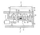
図4に本発明の要部斜視図を示し、図5に本発明の要部断面図を示して、以下、第1の実施形態について本発明を説明する。図4に示されるように、取付部材3は、垂直板部3aと、この垂直板部3aの下端から水平に延出する取付部3bとから構成されている。図5に示される実施形態では、取付部3bの上方に平行に離間して垂直板部3aの途中部分に接続した閉塞板部3cが形成されている。垂直板部3aの上部は、テンプル1bの前端に固着される固着部3dとなっている。(First embodiment)
FIG. 4 shows a perspective view of the main part of the present invention, FIG. 5 shows a cross-sectional view of the main part of the present invention, and the present invention will be described below for the first embodiment. As shown in FIG. 4, the attachment member 3 includes a
取付部3bには、ピン穴3e及びロック穴3fが連通形成されている。図に示される実施形態では、ロック穴3fの断面形状は、長方形状(正方形を含む)となっている。また、図4に示される実施形態では、ピン穴3e及びロック穴3fは、所定の間隔をおいてそれぞれ2つ形成されている。 A
図4に示されるように、画像生成部2の後部上面には、上方に開口した、取付凹部2aが凹陥形成されている。取付凹部2aは、取付部材3の取付部3bの外縁形状に対応した形状になっていて、前記取付部3bが取付凹部2a内に侵入することができるようになっている。取付凹部2aの底面には、所定間隔をおいて2つのピン2bが突設されている。ピン2bは、取付部材3のピン穴3eに侵入するようになっている。ピン2bの先端形状は、ピン穴3e内に侵入し易いように、尖鋭な形状となっている。取付凹部2aの底面には、所定間隔をおいて、2つの貫通穴2cが形成されている。取付凹部2aの底面には、コイルスプリング2dが取り付けられている。このコイルスプリング2dは、上下方向に圧縮されるようになっている。 As shown in FIG. 4, a mounting
図5に示されるように、画像生成部2の内部には、ロック部材5が横方向にスライド自在に収納されている。ロック部材5には、所定間隔をおいて、板状のロック部5aが形成されている。図5に示されるように、ロック部5aは、取付凹部2aの底面に形成された貫通穴2cを貫通して、この貫通穴2cから外部に突出している。ロック部5aの先端の片面には、ロック部5aの先端から基端側に向けて徐々に横幅が広くなっている形状のロック突起5bが突設されている。ロック突起5bには、ロック部5aの先端から基端方向に向かって、傾斜面5dが形成されている。ロック突起5bの下端には、ロック部5aと垂直に交わる水平な面の係止面5cが形成されている。 As shown in FIG. 5, the
画像生成部2の内部には、スプリング6が収納されている。スプリング6の一端は、画像生成部2の内壁に取り付けられ、スプリング6の他端は、ロック部材5に取り付けられている。スプリング6は、ロック部材5を、ロック突起5bが突設されている側に、付勢している。 A spring 6 is housed inside the
画像生成部2の内部には、アクチュエータ7が収納され、取り付けられている。このアクチュエータ7は、電動式のものであり、横方向にスライドするシャフト7aを有している。シャフト7aの先端は、ロック部材5に固着している。アクチュエータ7に電力を投入すると、シャフト7aが、ロック突起5bの突設方向と反対側にスライドする。アクチュエータ7は、電力が投入された際に、後述するロック手段に作動力を付与する作動力付与手段となっている。 An actuator 7 is housed and attached inside the
頭部装着部1と画像生成部2が分離している状態から、画像生成部2を頭部装着部1に取り付けるには、ピン2bをピン穴3eに挿入させるようにして、画像生成部2を取付部材3側に移動させる。すると、ピン2bがピン穴3eにガイドされながら、ロック部5aの先端が、ロック穴3f内に侵入する。この際に、ロック突起5bの傾斜面5dが、ロック穴3fの側面と当接し、スライド部材5がロック突起5bの突設方向と反対方向にスライドしながら、ロック突起5bがロック穴3f内に侵入し、ロック突起5bの係止面5cがロック穴3fを乗り越えると、スプリング6の付勢力により、スライド部材5がロック突起5bの突設されている側にスライドし、ロック状態となり(図5の状態)、画像生成部2が取付部材3に結合される。この際に、コイルスプリング2dは、取付部3bと当接して、圧縮される。ロック状態では、係止面5cが取付部3bの上面と密接し、ロック突起5bがロック穴3fを乗り越えることができないので、画像生成部2が取付部材3から外れることがない。 In order to attach the
画像生成部2が取付部材3を介して頭部装着部1に取り付けられている状態において、アクチュエータ7に電力が投入されると、シャフト7aがスライドして、ロック部材5が、ロック突起5bの突設方向と反対側にスライドし、ロック突起5bがロック穴3efを乗り越えることができる状態となり、画像生成部2と取付部材3との結合状態が解除され、コイルスプリング2dの付勢力や重力により、画像生成部2が取付部材3から離脱する。 When power is applied to the actuator 7 in a state where the
このように、ロック部材5と、取付部材3に形成されたロック穴3fとから、常時は画像生成部2を取付部材3に結合させているが、作動力が付与されると、画像生成部2と取付部材3との結合を解除するロック手段が構成されている。ロック手段は、図4や図5に示されるような構造に限定されず、常時は画像生成部2を取付部材3に結合させているが、作動力が付与されると、画像生成部2と取付部材3との結合を解除する構造のものであれば全て含まれる。 As described above, the
近接センサー4が障害物の近接を検知すると、CPU41からリリースドライバ65に信号が投入され、リリースドライバ65がアクチュエータ7に電力を投入する。すると、シャフト7aがスライドすることにより、前述したように、画像生成部2が取付部材3から脱落し、障害物と画像生成部2とが衝突することがない。画像生成部2が取付部材3から脱落しても、線材支持部材9により、ケーブル8が支持されているので、画像生成部2が落下することがなく、ケーブル8で吊された状態となる。このため、画像生成部2が破損することがない。 When the proximity sensor 4 detects the proximity of an obstacle, a signal is input from the
(第2の実施形態)
図6に第2の実施形態の要部斜視図を示し、図7に要部断面図を示す。第2の実施形態の頭部装着部1の構造は、第1の実施形態の頭部装着部1と同一である。以下、第1の実施形態と異なる点について、第2の実施形態のヘッドマウントディスプレイを説明する。図6に示されるように、取付部材13は、垂直板部13aと、この垂直板部13aの下端から水平に延出する水平板部13bとから構成されている。垂直板部13aの上部は、テンプル1bの前端に固着される固着部13dとなっている。(Second Embodiment)
FIG. 6 shows a perspective view of relevant parts of the second embodiment, and FIG. 7 shows a cross-sectional view of relevant parts. The structure of the
水平板部13bの下面には、鉄板等の板状の磁性部材14が取り付けられている。 A plate-like
図6に示されるように、画像生成部2の後部上面には、上方に開口した、取付凹部2eが凹陥形成されている。取付凹部2eは、取付部材13の水平部13b及び磁性部材14の外縁形状に対応した形状になっていて、水平部13b及び磁性部材14が取付凹部2e内に侵入することができるようになっている。 As shown in FIG. 6, a mounting
取付凹部2eの底面には、板状のマグネットであるマグネット16が取り付けられている。このため、マグネット16の磁力により、取付部材13に取り付けられた磁性部材14を吸着し、画像生成部2が取付部材13に結合されるようになっている。 A
図6、図7に示される第2の実施形態では、2つの貫通穴16aが、マグネット16に貫通形成されている。図7に示されるように、取付凹部2eの底面の貫通穴16aに対応する位置には、画像生成部2の内部に連通する連通穴2fが形成されている。 In the second embodiment shown in FIGS. 6 and 7, two through
図7に示されるように、画像生成部2の内部には、アクチュエータ15が収納され取り付けられている。図7に示される第2の実施形態では、アクチュエータ15は、上下方向にスライドするプッシャー15aを有するプッシュソレノイドである。アクチュエータ15に電力が投入されると、プッシャー15aが上方にスライドし、マグネット16の貫通穴16aから突出し、磁性部材14を押圧する。磁性部材14がプッシャー15aで押圧されると、磁性部材14とマグネット16が離間し、磁性部材14とマグネット16との磁力による結合が解除され、画像生成部2が取付部材13から脱落するようになっている。 As shown in FIG. 7, an
このように、図6、図7に示される第2の実施形態では、プッシャー15aを有するアクチュエータ15により、磁性部材14とマグネット16を離間させ、磁性部材14とマグネット16との磁力による結合を解除させる離間手段を構成しているが、離間手段はこのような構成に限定されず、磁性部材14とマグネット16を離間させる構造のものであれば全て含まれる。 As described above, in the second embodiment shown in FIGS. 6 and 7, the
近接センサー4が障害物の近接を検知すると、リリースドライバ65に信号が投入され、リリースドライバ65がアクチュエータ15に電力を投入する。すると、プッシャー15aが、磁性部材14を押圧し、前述したように、画像生成部2が取付部材13から脱落し、障害物と画像生成部2とが衝突することがない。画像生成部2が取付部材13から脱落しても、線材支持部材9により、ケーブル8が支持されているので、画像生成部2が落下することがなく、ケーブル8で吊された状態となる。このため、画像生成部2が破損することがない。 When the proximity sensor 4 detects the proximity of an obstacle, a signal is input to the
なお、取付部材13の水平部13bの下面に、磁性部材14を取り付けた実施形態について第2の実施形態を説明したが、取付部材13を磁性材で構成すれば磁性部材14は不要である。また、マグネット16を、取付部材13側に取り付け、磁性部材14を画像生成部2側に取り付けた実施形態であっても差し支えない。 In addition, although 2nd Embodiment was described about embodiment which attached the
(第3の実施形態)
図8に第3の実施形態の要部斜視図を示し、図9に要部横断面図を示し、図10に要部縦断面図を示す。第3の実施形態の頭部装着部1の構造は、第1の実施形態の頭部装着部1と同一である。以下、第1の実施形態と異なる点について、第3の実施形態のヘッドマウントディスプレイ本体10を説明する。なお、第3の実施形態では、近接センサー4やリリースドライバ65、アクチュエータは不要である。(Third embodiment)
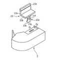
FIG. 8 shows a perspective view of the main part of the third embodiment, FIG. 9 shows a cross-sectional view of the main part, and FIG. 10 shows a vertical cross-sectional view of the main part. The structure of the
図8に示されるように、取付部材23は、垂直板部23aと、この垂直板部23aの下端から水平に延出する水平板部23bとから構成されている。垂直板部23aの上部は、テンプル1bの前端に固着される固着部23dとなっている。 As shown in FIG. 8, the
水平板部23bの下面から下方に、係合突起23eが突設されている。係合突起23eの途中部分の両側には、係合凹部23fが形成されている。係合突起23eの先端23hは、係合突起23eの係合凹部23fが形成されている部分の幅よりも広くなっている。係合突起23eの表面の係合凹部23fが形成されている位置には、押圧突起23gが突設されている。図8〜10に示される実施形態では、押圧突起23gは、係合突起23eの両面に、上下に突設されている。 An engaging
図8に示されるように、画像生成部2の基部には、上方に開口した、取付凹部2gが凹陥形成されている。取付凹部2gは、取付部材23の水平部23bの外縁形状に対応した形状になっていて、前記水平部23bが取付凹部2g内に侵入することができるようになっている。取付凹部2gの底面には、画像生成部2の内部に連通する係合穴2hが形成されている。係合穴2hは、長穴形状若しくは長方形状をしている。係合穴2hに、係合突起23eが侵入可能になっている。 As shown in FIG. 8, a mounting recess 2 g that opens upward is formed in the base of the
図10に示されるように、画像生成部2の内部には、一対のスライド部材24が、その先端で対向して、係合穴2hの下方両方向から、係合穴2hの直下に突出するように、横方向スライド自在に配設されている。一対のスライド部材24の先端24aは、係合穴2hの直下に位置している。略円弧形状の板バネ25が、一対のスライド部材24の先端24a部分に、ピン26で取り付けられている。板バネ25は、係合穴2h方向に膨出している。板バネ25によって、一対のスライド部材24が、互いに近接する方向に付勢され、一対のスライド部材24が、引き合わされるようになっている。図9の(A)に示されるように、板バネ25は、スライド部材24から離間している。 As shown in FIG. 10, a pair of
画像生成部2を、取付部材23を介して、頭部装着部1に取り付けるには、係合突起23eを、係合穴2h内に挿入させる(図10の(A)の状態)。すると、係合突起23eの先端23hが、互いに引き合わされているスライド部材24の先端24aを押し拡げ、係合突起23eの先端部23hが、一対のスライド部材24の先端24aを乗り越えると、一対のスライド部材24の先端24aが、係合突起23eの係合凹部23fを挟持する(図10の(B)の状態)。スライド部材24の先端24aの形状は、係合突起23eの係合凹部23fに対応した形状となっている。このため、一対のスライド部材24の先端24aが、係合突起23eの係合凹部23fと係合し、画像生成部2と取付部材23とが結合する。係合凹部23fとスライド部材24とが係合している状態では、図9の(A)に示されるように、一対のスライド部材24と、係合突起23eとが一直線に配置されている。 In order to attach the
係合突起23eの先端23hが、互いに引き合わされているスライド部材24の先端24aを押し拡げる際に、押圧突起23gが板バネ25を押圧し、図10の(B)に示されるように、板バネ25が変形する。係合突起23eと、一対のスライド部材24が係合している状態では、板バネ25が、係合突起23eを上方に付勢している。 When the
画像生成部2が、取付部材23に結合している状態で、画像生成部2に障害物が当接すると、図9の(B)に示されるように係合突起23eに対して、スライド部材24が傾き(B)、係合凹部23fとスライド部材24との係合状態が解除される(図9の(C)の状態)。係合凹部23fとスライド部材24との係合状態が解除されると、係合突起23eは、板バネ25により、上方に付勢されているので、係合突起23eが、係合穴2hから脱出し、画面生成部2が、取付部材23から脱落する。障害物が接触した瞬間に、板バネ25により係合突起23eが係合穴2hからすばやく押し出されるので、画面生成部2が眼に接触するのを防止できる When an obstacle is brought into contact with the
例えば工場の加工現場等の機械作業を行う場所で、作業支援等の目的でヘッドマウントディスプレイが用いられる場合に、第3の実施形態で提供される様な脱落手段が無いと、機械にケーブル8が巻き込まれたときに画像生成部2と頭部装着部1とが一体となって引っ張られるので、ユーザがその機械に巻き込まれる可能性がある。しかし、第3の実施形態のように脱落手段を有していれば、機械にケーブル8が巻き込まれても、画像生成部2が頭部装着部1から脱落するので、ユーザがその機械に巻き込まれる危険を防止することが可能となる。 For example, when a head-mounted display is used for the purpose of work support at a place where machine work such as a factory processing site is performed, if there is no drop-off means as provided in the third embodiment, the
以上の説明では、画像生成部2は、強度が画像に応じて変調された光を2次元に走査した走査画像光を生成し、当該走査画像光をユーザの眼球に直接照射し、ユーザに画像を視認させる装置であるが、本発明の画像生成部2はこれに限定されず、LCD等の表示装置を用い、ユーザに画像を視認させるものであれば全て含まれる。 In the above description, the
以上説明した、ヘッドマウントディスプレイは、1つの画像生成部2が、頭部装着部1の側前部に取り付けられているが、2つの画像生成部2が頭部装着部1の両側前部に取り付けられ、ユーザが両眼で画像を視認することができるヘッドマウントディスプレイであっても差し支えない。また、以上説明したヘッドマウントディスプレイの、頭部装着部1は、眼鏡のフレーム形状をしているが、頭部装着部1は、この形状に限定されず、ヘルメット形状等であってもよく、ユーザの頭部に装着される構造のものであれはすべて含まる。このような構造のヘッドマウントディスプレイにも、本発明を適用することができることは言うまでもない。 In the head-mounted display described above, one
以上、現時点において、もっとも、実践的であり、かつ好ましいと思われる実施形態に関連して本発明を説明したが、本発明は、本願明細書中に開示された実施形態に限定されるものではなく、請求の範囲および明細書全体から読み取れる発明の要旨あるいは思想に反しない範囲で適宜変更可能であり、そのような変更を伴うヘッドマウントディスプレイもまた技術的範囲に包含されるものとして理解されなければならない。 Although the present invention has been described above in connection with the most practical and preferred embodiments at the present time, the present invention is not limited to the embodiments disclosed herein. However, the present invention can be appropriately changed without departing from the gist or concept of the invention that can be read from the claims and the entire specification, and a head-mounted display accompanying such a change should also be understood as being included in the technical scope. I must.
1 頭部装着部
1a フロントフレーム
1b テンプル
1c ノーズパッド
1d イヤーパッド
1f 線材支持部
2 画像生成部
2a 取付凹部(第2の実施形態)
2b ピン
2c 貫通穴
2d コイルスプリング
2e 取付凹部(第2の実施形態)
2f 連通穴
2g 取り付け凹部(第3の実施形態)
2h 係合穴
3 取付部材
3a 垂直板部
3b 取付部
3c 閉塞板部
3d 固着部
3e ピン穴
3f ロック穴
4 近接センサー
5 ロック突起材
5a ロック部
5b ロック突起
5c 係止面
5d 傾斜面
6 スプリング
7 アクチュエータ
7a シャフト
8 ケーブル
8a 画像・制御信号伝送線
9 線材支持部材
9a 支持穴
10 ヘッドマウントディスプレイ本体
13 取付部材(第2の実施形態)
13a 垂直板部
13b 水平板部
13d 固着部
14 磁性部材
15 アクチュエータ(第2の実施形態)
15a プッシャー
16 マグネット
16a 貫通形成
23 取付部材(第3の実施形態)
23a 垂直板部
23b 水平板部
23d 固着部
23e 係合突起
23f 係合凹部
23g 係合突起
23h 係合突起の先端
24 スライド部材
24a スライド部材の先端
25 板バネ
26 ピン
30 走査画像光照射部
31 光源
32 コリメート光学系
33 走査光生成部
34 接眼レンズ
34a レンズ系
34b レンズ系
35 ミラー
40 制御部
41 CPU
42 RAM
43 ROM
44 不揮発性メモリー
46 周辺インターフェース
47 画像入力インターフェース
48 VRAM
49 コントローラ
55 バス
60 操作部
61 電源ランプ
65 リリースドライバ
91 パーソナルコンピュータ
50 従来のヘッドマウントディスプレイ
51 頭部装着部
51a ノーズパッド
51b イヤーパッド
52 画像生成部
52a ハーフミラー
55 バス
100 ヘッドマウントディスプレイ
E 眼球DESCRIPTION OF
2f communication hole 2g mounting recess (third embodiment)
2h engagement hole 3
13a
23a
42 RAM
43 ROM
44
49
Claims (4)
Translated fromJapanese前記頭部装着部の前側方に取り付けられ、前記ユーザに画像を視認させる画像生成部を有するヘッドマウントディスプレイにおいて、
障害物が前記画像生成部に近接又は接触した際に、前記画像生成部を前記頭部装着部から脱落させる脱落手段を設けたことを特徴とするヘッドマウントディスプレイ。A head mounting part to be mounted on the user's head;
In the head mounted display having an image generation unit attached to the front side of the head mounting unit and allowing the user to visually recognize an image,
A head-mounted display provided with a drop-off means for dropping the image generation unit from the head-mounted unit when an obstacle approaches or contacts the image generation unit.
頭部装着部に設けられた取付部材と、
常時は画像生成部を前記取付部材に結合させているが、作動力が付与されると、画像生成部と前記取付部材との結合を解除するロック手段と、
電力が投入された際に、前記ロック手段に作動力を付与する作動力付与手段と、
障害物の画像生成部への近接を検知する近接検知手段と、
前記近接検知手段が障害物の画像生成部への近接を検知した際に、前記作動力付与手段に電力を投入する電力入力手段とから構成されることを特徴とする請求項1に記載のヘッドマウントディスプレイ。The drop-off means is
A mounting member provided in the head mounting portion;
Normally, the image generating unit is coupled to the mounting member, but when an actuation force is applied, a lock unit that releases the coupling between the image generating unit and the mounting member;
An operating force applying means for applying an operating force to the locking means when electric power is applied;
Proximity detection means for detecting the proximity of the obstacle to the image generation unit;
2. The head according to claim 1, further comprising: a power input unit that supplies power to the operating force applying unit when the proximity detecting unit detects the proximity of the obstacle to the image generation unit. Mount display.
頭部装着部に設けられた取付部材と、
前記取付部材及び画像生成部の一方に取り付けられた磁性部材と、
前記取付部材及び画像生成部の他方に取り付けられ、前記磁性部材と磁力により結合させるマグネットと、
電力が投入された際に、前記磁性部材と前記マグネットとを離間させることにより、磁力による結合を解除させる離間手段と、
障害物の画像生成部への近接を検知する近接検知手段と、
障害物の画像生成部への近接を検知した際に、前記離間手段に電力を投入するリリースドライバとから構成されることを特徴とする請求項1に記載のヘッドマウントディスプレイ。The drop-off means is
A mounting member provided in the head mounting portion;
A magnetic member attached to one of the attachment member and the image generator;
A magnet attached to the other of the attachment member and the image generation unit, and coupled to the magnetic member by a magnetic force;
Separating means for releasing the coupling by magnetic force by separating the magnetic member and the magnet when power is applied;
Proximity detection means for detecting the proximity of the obstacle to the image generation unit;
The head-mounted display according to claim 1, further comprising a release driver that turns on power to the separation unit when the proximity of the obstacle to the image generation unit is detected.
頭部装着部に設けられた取付部材と、
前記取付部材及び画像生成部の一方に突設され、その途中部分に係合凹部を有する係合突起と、
前記取付部材及び画像生成部の他方に凹陥形成され、前記係合手段が侵入する係合穴と、
前記係合侵入穴の両側方から、前記係合穴内に突出するようにスライド自在に配設され、その先端が前記係合突起の係合凹部に係合することで、前記係合突起を挟持する一対の挟持部材と、
前記一対の挟持部材を、互いに近接させる方向に付勢する付勢部材とから構成されることを特徴とする請求項1に記載のヘッドマウントディスプレイ。The drop-off means is
A mounting member provided in the head mounting portion;
An engagement protrusion that protrudes from one of the attachment member and the image generation unit and has an engagement recess in the middle of the attachment member;
An engagement hole formed in a recess in the other of the attachment member and the image generation unit, and into which the engagement means enters,
It is slidably disposed so as to protrude into the engagement hole from both sides of the engagement entry hole, and the tip of the engagement protrusion engages with the engagement recess of the engagement protrusion, thereby holding the engagement protrusion. A pair of clamping members that
The head-mounted display according to claim 1, wherein the pair of sandwiching members includes a biasing member that biases the pair of sandwiching members toward each other.
Priority Applications (2)
| Application Number | Priority Date | Filing Date | Title |
|---|---|---|---|
| JP2008313887AJP5126682B2 (en) | 2008-12-10 | 2008-12-10 | Head mounted display |
| PCT/JP2009/070377WO2010067758A1 (en) | 2008-12-10 | 2009-12-04 | Head-mounted display |
Applications Claiming Priority (1)
| Application Number | Priority Date | Filing Date | Title |
|---|---|---|---|
| JP2008313887AJP5126682B2 (en) | 2008-12-10 | 2008-12-10 | Head mounted display |
Publications (2)
| Publication Number | Publication Date |
|---|---|
| JP2010141453A JP2010141453A (en) | 2010-06-24 |
| JP5126682B2true JP5126682B2 (en) | 2013-01-23 |
Family
ID=42242746
Family Applications (1)
| Application Number | Title | Priority Date | Filing Date |
|---|---|---|---|
| JP2008313887AExpired - Fee RelatedJP5126682B2 (en) | 2008-12-10 | 2008-12-10 | Head mounted display |
Country Status (2)
| Country | Link |
|---|---|
| JP (1) | JP5126682B2 (en) |
| WO (1) | WO2010067758A1 (en) |
Cited By (6)
| Publication number | Priority date | Publication date | Assignee | Title |
|---|---|---|---|---|
| JP2613044B2 (en) | 1987-02-25 | 1997-05-21 | 横浜ゴム株式会社 | Pneumatic radial tire |
| JP2614459B2 (en) | 1987-09-28 | 1997-05-28 | 横浜ゴム株式会社 | Flat radial tire |
| WO2015108234A1 (en)* | 2014-01-15 | 2015-07-23 | Lg Electronics Inc. | Detachable head mount display device and method for controlling the same |
| US11106034B2 (en)* | 2019-05-07 | 2021-08-31 | Apple Inc. | Adjustment mechanism for head-mounted display |
| US12298519B2 (en) | 2018-09-24 | 2025-05-13 | Apple Inc. | Display system with interchangeable lens |
| US12360367B2 (en) | 2019-06-21 | 2025-07-15 | Apple Inc. | Display and vision correction system with removable lens |
Families Citing this family (8)
| Publication number | Priority date | Publication date | Assignee | Title |
|---|---|---|---|---|
| JP5617375B2 (en) | 2010-06-22 | 2014-11-05 | ソニー株式会社 | Image display device, display control method, and program |
| JP5594258B2 (en) | 2011-08-23 | 2014-09-24 | ブラザー工業株式会社 | Head mounted display |
| JP6206437B2 (en)* | 2015-03-30 | 2017-10-04 | ブラザー工業株式会社 | Image display device and head mounted display |
| TWI530709B (en)* | 2015-06-05 | 2016-04-21 | 中強光電股份有限公司 | Head-mounted display |
| US10952479B2 (en) | 2018-09-25 | 2021-03-23 | Sony Corporation | Protection for head mounted display device |
| CN209801114U (en)* | 2019-04-18 | 2019-12-17 | 上海肇观电子科技有限公司 | connecting piece, auxiliary assembly, wearable equipment and wearable equipment external member |
| KR102375545B1 (en) | 2019-04-18 | 2022-03-16 | 넥스트브이피유 (상하이) 코포레이트 리미티드 | Connectors, assistive devices, wearable devices and wearable device sets |
| CN112860078A (en)* | 2021-02-19 | 2021-05-28 | 歌尔光学科技有限公司 | Head-mounted display device control method, head-mounted display device, and storage medium |
Family Cites Families (5)
| Publication number | Priority date | Publication date | Assignee | Title |
|---|---|---|---|---|
| JPH05304646A (en)* | 1992-04-24 | 1993-11-16 | Sony Corp | Video display device |
| GB2301216A (en)* | 1995-05-25 | 1996-11-27 | Philips Electronics Uk Ltd | Display headset |
| JP4321083B2 (en)* | 2003-01-31 | 2009-08-26 | 株式会社ニコン | Head mounted display |
| JP4192612B2 (en)* | 2003-01-31 | 2008-12-10 | 株式会社ニコン | Head mounted display device |
| JP3117396U (en)* | 2005-10-06 | 2006-01-05 | 株式会社島津製作所 | Head mounted display |
- 2008
- 2008-12-10JPJP2008313887Apatent/JP5126682B2/ennot_activeExpired - Fee Related
- 2009
- 2009-12-04WOPCT/JP2009/070377patent/WO2010067758A1/enactiveApplication Filing
Cited By (8)
| Publication number | Priority date | Publication date | Assignee | Title |
|---|---|---|---|---|
| JP2613044B2 (en) | 1987-02-25 | 1997-05-21 | 横浜ゴム株式会社 | Pneumatic radial tire |
| JP2614459B2 (en) | 1987-09-28 | 1997-05-28 | 横浜ゴム株式会社 | Flat radial tire |
| WO2015108234A1 (en)* | 2014-01-15 | 2015-07-23 | Lg Electronics Inc. | Detachable head mount display device and method for controlling the same |
| US9348142B2 (en) | 2014-01-15 | 2016-05-24 | Lg Electronics Inc. | Detachable head mount display device and method for controlling the same |
| US9599823B2 (en) | 2014-01-15 | 2017-03-21 | Lg Electronics Inc. | Detachable head mount display device and method for controlling the same |
| US12298519B2 (en) | 2018-09-24 | 2025-05-13 | Apple Inc. | Display system with interchangeable lens |
| US11106034B2 (en)* | 2019-05-07 | 2021-08-31 | Apple Inc. | Adjustment mechanism for head-mounted display |
| US12360367B2 (en) | 2019-06-21 | 2025-07-15 | Apple Inc. | Display and vision correction system with removable lens |
Also Published As
| Publication number | Publication date |
|---|---|
| JP2010141453A (en) | 2010-06-24 |
| WO2010067758A1 (en) | 2010-06-17 |
Similar Documents
| Publication | Publication Date | Title |
|---|---|---|
| JP5126682B2 (en) | Head mounted display | |
| JP5800616B2 (en) | Manipulator system | |
| JP5223689B2 (en) | Head mounted display device and driving method thereof | |
| US10718950B2 (en) | Head-mounted display apparatus | |
| JP2019080354A (en) | Head-mounted display | |
| JP4675469B2 (en) | Thermal printer unit and thermal printer device | |
| JP6492531B2 (en) | Display device and control method of display device | |
| JP2010147727A (en) | Mounting instrument for head-mounted display, head-mounted display, and endoscopic surgery system | |
| WO2010101081A1 (en) | Head-mounted display apparatus, image control method, and image control program | |
| JP2015055638A (en) | Head-mounted display capable of adjusting image viewing distance | |
| JP2013206412A (en) | Head-mounted display and computer program | |
| WO2017110370A1 (en) | Image projection device | |
| JP2015213226A (en) | Wearable display and display control program therefor | |
| JP2011180414A (en) | Fixing structure of camera unit | |
| JP4022921B2 (en) | Retina scanning display device | |
| JP5530326B2 (en) | Support member for equipment mounting | |
| JP6011563B2 (en) | Image display device and head mounted display | |
| WO2013128573A1 (en) | Display device and display method | |
| JP2012063627A (en) | Head-mounted type display device | |
| JP2011065392A (en) | Head mounted display | |
| JP4973423B2 (en) | Head-mounted image display device | |
| US20240310640A1 (en) | Head-mounted display | |
| JP6347067B2 (en) | Eyeglass type display device | |
| JP6314339B2 (en) | Eyeglass type display device | |
| JP5375481B2 (en) | Head mounted display |
Legal Events
| Date | Code | Title | Description |
|---|---|---|---|
| A621 | Written request for application examination | Free format text:JAPANESE INTERMEDIATE CODE: A621 Effective date:20110310 | |
| TRDD | Decision of grant or rejection written | ||
| A01 | Written decision to grant a patent or to grant a registration (utility model) | Free format text:JAPANESE INTERMEDIATE CODE: A01 Effective date:20121005 | |
| A01 | Written decision to grant a patent or to grant a registration (utility model) | Free format text:JAPANESE INTERMEDIATE CODE: A01 | |
| A61 | First payment of annual fees (during grant procedure) | Free format text:JAPANESE INTERMEDIATE CODE: A61 Effective date:20121018 | |
| R150 | Certificate of patent or registration of utility model | Free format text:JAPANESE INTERMEDIATE CODE: R150 Ref document number:5126682 Country of ref document:JP Free format text:JAPANESE INTERMEDIATE CODE: R150 | |
| FPAY | Renewal fee payment (event date is renewal date of database) | Free format text:PAYMENT UNTIL: 20151109 Year of fee payment:3 | |
| LAPS | Cancellation because of no payment of annual fees |