JP5124103B2 - Computer system - Google Patents
Computer systemDownload PDFInfo
- Publication number
- JP5124103B2 JP5124103B2JP2006136869AJP2006136869AJP5124103B2JP 5124103 B2JP5124103 B2JP 5124103B2JP 2006136869 AJP2006136869 AJP 2006136869AJP 2006136869 AJP2006136869 AJP 2006136869AJP 5124103 B2JP5124103 B2JP 5124103B2
- Authority
- JP
- Japan
- Prior art keywords
- storage system
- logical unit
- storage
- logical
- host computer
- Prior art date
- Legal status (The legal status is an assumption and is not a legal conclusion. Google has not performed a legal analysis and makes no representation as to the accuracy of the status listed.)
- Expired - Fee Related
Links
Images


Classifications
- G—PHYSICS
- G06—COMPUTING OR CALCULATING; COUNTING
- G06F—ELECTRIC DIGITAL DATA PROCESSING
- G06F3/00—Input arrangements for transferring data to be processed into a form capable of being handled by the computer; Output arrangements for transferring data from processing unit to output unit, e.g. interface arrangements
- G06F3/06—Digital input from, or digital output to, record carriers, e.g. RAID, emulated record carriers or networked record carriers
- G06F3/0601—Interfaces specially adapted for storage systems
- G06F3/0628—Interfaces specially adapted for storage systems making use of a particular technique
- G06F3/0662—Virtualisation aspects
- G06F3/0665—Virtualisation aspects at area level, e.g. provisioning of virtual or logical volumes
- G—PHYSICS
- G06—COMPUTING OR CALCULATING; COUNTING
- G06F—ELECTRIC DIGITAL DATA PROCESSING
- G06F3/00—Input arrangements for transferring data to be processed into a form capable of being handled by the computer; Output arrangements for transferring data from processing unit to output unit, e.g. interface arrangements
- G06F3/06—Digital input from, or digital output to, record carriers, e.g. RAID, emulated record carriers or networked record carriers
- G06F3/0601—Interfaces specially adapted for storage systems
- G06F3/0602—Interfaces specially adapted for storage systems specifically adapted to achieve a particular effect
- G06F3/0608—Saving storage space on storage systems
- G—PHYSICS
- G06—COMPUTING OR CALCULATING; COUNTING
- G06F—ELECTRIC DIGITAL DATA PROCESSING
- G06F3/00—Input arrangements for transferring data to be processed into a form capable of being handled by the computer; Output arrangements for transferring data from processing unit to output unit, e.g. interface arrangements
- G06F3/06—Digital input from, or digital output to, record carriers, e.g. RAID, emulated record carriers or networked record carriers
- G06F3/0601—Interfaces specially adapted for storage systems
- G06F3/0602—Interfaces specially adapted for storage systems specifically adapted to achieve a particular effect
- G06F3/061—Improving I/O performance
- G06F3/0613—Improving I/O performance in relation to throughput
- G—PHYSICS
- G06—COMPUTING OR CALCULATING; COUNTING
- G06F—ELECTRIC DIGITAL DATA PROCESSING
- G06F3/00—Input arrangements for transferring data to be processed into a form capable of being handled by the computer; Output arrangements for transferring data from processing unit to output unit, e.g. interface arrangements
- G06F3/06—Digital input from, or digital output to, record carriers, e.g. RAID, emulated record carriers or networked record carriers
- G06F3/0601—Interfaces specially adapted for storage systems
- G06F3/0628—Interfaces specially adapted for storage systems making use of a particular technique
- G06F3/0629—Configuration or reconfiguration of storage systems
- G06F3/0635—Configuration or reconfiguration of storage systems by changing the path, e.g. traffic rerouting, path reconfiguration
- G—PHYSICS
- G06—COMPUTING OR CALCULATING; COUNTING
- G06F—ELECTRIC DIGITAL DATA PROCESSING
- G06F3/00—Input arrangements for transferring data to be processed into a form capable of being handled by the computer; Output arrangements for transferring data from processing unit to output unit, e.g. interface arrangements
- G06F3/06—Digital input from, or digital output to, record carriers, e.g. RAID, emulated record carriers or networked record carriers
- G06F3/0601—Interfaces specially adapted for storage systems
- G06F3/0628—Interfaces specially adapted for storage systems making use of a particular technique
- G06F3/0646—Horizontal data movement in storage systems, i.e. moving data in between storage devices or systems
- G06F3/0647—Migration mechanisms
- G—PHYSICS
- G06—COMPUTING OR CALCULATING; COUNTING
- G06F—ELECTRIC DIGITAL DATA PROCESSING
- G06F3/00—Input arrangements for transferring data to be processed into a form capable of being handled by the computer; Output arrangements for transferring data from processing unit to output unit, e.g. interface arrangements
- G06F3/06—Digital input from, or digital output to, record carriers, e.g. RAID, emulated record carriers or networked record carriers
- G06F3/0601—Interfaces specially adapted for storage systems
- G06F3/0668—Interfaces specially adapted for storage systems adopting a particular infrastructure
- G06F3/067—Distributed or networked storage systems, e.g. storage area networks [SAN], network attached storage [NAS]
Landscapes
- Engineering & Computer Science (AREA)
- Theoretical Computer Science (AREA)
- Human Computer Interaction (AREA)
- Physics & Mathematics (AREA)
- General Engineering & Computer Science (AREA)
- General Physics & Mathematics (AREA)
- Computer Networks & Wireless Communication (AREA)
- Information Retrieval, Db Structures And Fs Structures Therefor (AREA)
- Memory System Of A Hierarchy Structure (AREA)
Description
Translated fromJapanese本発明はストレージ仮想化技術を適用したストレージシステムを有する計算機システムに関する。 The present invention relates to a computer system having a storage system to which a storage virtualization technology is applied.
インターネットビジネスの拡大、手続きの電子化など、急速に情報システムが進展する中、コンピュータが送受信するデータ量は、飛躍的に増加している。このようなデータ量の飛躍的増加に加え、ディスク装置へのデータバックアップ(Disk−to−DiskBackup)や監査対応などによる企業の業務活動記録(取引情報やメールなど)の長期保管など、ストレージに格納するデータ量も飛躍的に増加を続けている。これに伴い、企業情報システムにおいて、各部門/各システムのストレージの増強を図る一方で、複雑化するITインフラストラクチャの管理の簡素化や効率化が求められている。特にストレージの管理を簡素化し、データの価値に応じ最適なストレージを活用してトータルコストの最適化を図る技術に対する期待が高まっている。 With the rapid development of information systems, such as the expansion of the Internet business and the digitization of procedures, the amount of data transmitted and received by computers has increased dramatically. In addition to this dramatic increase in data volume, data backup to disk devices (Disk-to-Disk Backup) and long-term storage of corporate business activity records (transaction information, e-mail, etc.) by auditing etc. are stored in storage. The amount of data to be continued continues to increase dramatically. Along with this, in the enterprise information system, while the storage of each department / each system is to be increased, the management of the complicated IT infrastructure is required to be simplified and efficient. In particular, there is an increasing expectation for a technology that simplifies storage management and optimizes the total cost by utilizing the optimal storage according to the value of data.
大規模ストレージを有するシステムの管理コストを低減する方法として、特開平2005-011277号公報に開示されているようなストレージ仮想化技術を挙げることができる。特開平2005-011277号公報では、ホスト計算機に接続するストレージシステム(以下、第一のストレージシステムと称する。)を一つ以上の外部ストレージシステム(以下、第二のストレージシステムと称する。)に接続し、第二のストレージシステムが有するデバイス(以下、外部デバイスと称する。)をあたかも第一のストレージシステム内の論理デバイスであるかのように仮想化してホスト計算機に提供するストレージ仮想化技術(以下、外部ストレージ接続技術とも称する)が開示されている。第一のストレージシステムは、ホスト計算機からの論理デバイスへの入出力要求を受信すると、アクセス先のデバイスが第二のストレージシステム内の外部デバイスに対応しているのか、或いは第一のストレージシステムが搭載するディスク装置などの物理デバイス(内部デバイス)に対応しているのかを判定し、判定結果に従って適当なアクセス先に入出力要求を振り分ける。 An example of a method for reducing the management cost of a system having a large-scale storage is a storage virtualization technique as disclosed in Japanese Patent Laid-Open No. 2005-011277. In Japanese Patent Laid-Open No. 2005-011277, a storage system (hereinafter referred to as a first storage system) connected to a host computer is connected to one or more external storage systems (hereinafter referred to as a second storage system). A storage virtualization technology (hereinafter referred to as an external device) that is virtualized as if it is a logical device in the first storage system and provided to the host computer (hereinafter referred to as an external device). , Also referred to as external storage connection technology). When the first storage system receives an input / output request to the logical device from the host computer, the access destination device corresponds to an external device in the second storage system, or the first storage system It is determined whether it corresponds to a physical device (internal device) such as a mounted disk device, and I / O requests are distributed to appropriate access destinations according to the determination result.
特開平2005-011277号公報に示す外部ストレージ接続技術を利用したストレージシステムを用いると、性能、信頼性、価格などの属性の異なる複数のストレージシステムを統合したシステムを構築できる。例えば、外部ストレージ接続技術を利用した高コスト・高機能・高信頼な第一のストレージシステムと、低コスト・低機能・低信頼な第二のストレージシステムとを接続し、記憶領域を論理的に階層化することによって、データの更新日時やデータの価値に応じた最適なデータ配置が可能となる。階層化された記憶領域を有するストレージシステムを用いることで、監査対応などを目的として、日々の業務で発生する取引情報やメールなどの大量の情報を、各情報が持つ価値に応じて最適なコストで長期間保存することが可能となる。 When a storage system using the external storage connection technology disclosed in Japanese Patent Laid-Open No. 2005-011277 is used, a system in which a plurality of storage systems having different attributes such as performance, reliability, and price can be integrated can be constructed. For example, a high-cost, high-function, high-reliability first storage system that uses external storage connection technology and a low-cost, low-function, low-reliability second storage system are connected to logically store the storage area. Hierarchization enables optimal data placement according to the date and time of data update and the value of the data. By using a storage system with a tiered storage area, for the purpose of auditing etc., the optimal cost according to the value each information has for a large amount of information such as transaction information and e-mail generated in daily work Can be stored for a long time.
ところで、ストレージシステムの寿命を超えた数十年の長期にわたって大容量のデータを保存するには、データの保存期間中に計算機システムを構成する機器を交換する作業が必要になる。特開平2005-011277号公報では、外部ストレージ接続技術を適用した第一のストレージシステム(以下、移動元ストレージと称する。)を他の第一のストレージシステム(以下、移動先ストレージと称する。)に交換するために、移動元ストレージが有する論理ユニット(以下、移動元論理ユニットと称する。)内のデータを、移動先ストレージが有する論理ユニット(以下、移動先論理ユニットと称する。)へコピーして移動することが開示されている。
しかし、移動元論理ユニットから移動先論理ユニットへのコピー処理によって、移動元ストレージが行うデバイスの入出力処理にスループット低下などの悪影響を及ぼすことが懸念される。更に、移動元論理ユニット内のデータを全て移動先論理ユニットにコピーする必要があるため、移動元ストレージから移動先ストレージへのデバイス引継ぎに多くの時間を要するという問題が生じる。 However, there is a concern that copy processing from the migration source logical unit to the migration destination logical unit may adversely affect the device input / output processing performed by the migration source storage, such as a reduction in throughput. Furthermore, since it is necessary to copy all the data in the migration source logical unit to the migration destination logical unit, there arises a problem that it takes a lot of time to take over the device from the migration source storage to the migration destination storage.
また、ストレージ階層の複雑化を背景として、移動元論理ユニットと外部デバイスとが一対一に対応している場合のみならず、両者が一対一に対応していない場合も想定され得るところである。特に、移動元論理ユニットと外部デバイスとが一対一に対応してない場合においても、ホスト計算機が認識する記憶領域の単位である論理ユニット単位でのデータ移動を可能にすることが望ましい。 Further, with the background of the complexity of the storage hierarchy, not only the case where the source logical unit and the external device correspond one-to-one but also the case where the two do not correspond one-to-one can be assumed. In particular, even when the migration source logical unit and the external device do not have a one-to-one correspondence, it is desirable to enable data migration in units of logical units that are units of storage areas recognized by the host computer.
本発明の目的は、ストレージ仮想化技術を適用した計算機システムにおいて、計算機システムの構成変更に伴う論理ユニット単位でのデータ移動を、ストレージシステムの性能低下を抑制しつつ、可能とすることにある。 An object of the present invention is to enable data movement in units of logical units accompanying a change in the configuration of a computer system while suppressing deterioration in the performance of the storage system in a computer system to which a storage virtualization technology is applied.
本発明の他の目的は、ストレージ仮想化技術を適用した計算機システムにおいて、外部ボリュームを複数のストレージシステムによって共有することにある。 Another object of the present invention is to share an external volume by a plurality of storage systems in a computer system to which a storage virtualization technology is applied.
上記の課題を解決するため、本発明の計算機システムは、ホスト計算機と、外部ボリュームを有する外部ストレージシステムと、外部ボリュームを仮想化してなる第一の拡張デバイスと、第一の拡張デバイスを仮想化してなる、ホスト計算機から認識可能な第一の論理ユニットとを有する第一のストレージシステムと、外部ボリュームを仮想化してなる第二の拡張デバイスと、第二の拡張デバイスを仮想化してなる、ホスト計算機から認識可能な第二の論理ユニットとを有する第二のストレージシステムと、を備える。 In order to solve the above problems, a computer system of the present invention includes a host computer, an external storage system having an external volume, a first expansion device that virtualizes the external volume, and a first expansion device that is virtualized. A first storage system having a first logical unit recognizable from a host computer, a second expansion device obtained by virtualizing an external volume, and a host obtained by virtualizing the second expansion device And a second storage system having a second logical unit recognizable from the computer.
ここで、例えば、外部ストレージシステムは、外部ボリュームを構成する各記憶領域について、第一又は第二のストレージシステムのうち何れか一方のみの排他的アクセスを制御する。 Here, for example, the external storage system controls exclusive access to only one of the first and second storage systems for each storage area constituting the external volume.
ホスト計算機は、例えば、外部ボリュームを構成する各記憶領域についてアクセス権を有するストレージシステムに接続するためにパス切り替えを実行する。 For example, the host computer executes path switching in order to connect each storage area constituting the external volume to a storage system having an access right.
外部ボリュームは、第一及び第二のストレージシステムの双方からアクセスされる共用領域を含むものであってもよい。 The external volume may include a shared area accessed from both the first and second storage systems.
本発明の他の側面に関る計算機システムは、ホスト計算機と、外部ボリュームを有する外部ストレージシステムと、外部ボリュームを仮想化してなる第一の拡張デバイスと、ホスト計算機から認識できるように中間記憶階層を介して第一の拡張デバイスを仮想化してなる第一の論理ユニットとを有する第一のストレージシステムと、ホスト計算機及び外部ストレージシステムに接続可能な第二のストレージシステムと、を備える。第二のストレージシステムは、第一の論理ユニットを第一のストレージシステムから第二のストレージシステムに移動させる指示を受けると、外部ボリュームを仮想化する第二の拡張デバイスを第二のストレージシステム内に作成し、第一の論理ユニットを仮想化する第三の拡張デバイスを第二のストレージシステム内に作成し、第一の論理ユニットと第三の拡張デバイスを接続するパスを定義し、ホスト計算機から認識できるように第二のストレージシステム内の中間記憶階層を介して第三の拡張デバイスを仮想化してなる第二の論理ユニットを作成し、第二の論理ユニットとホスト計算機とを接続するパスを、第一の論理ユニットとホスト計算機とを接続するパスの交替パスとして設定する。ホスト計算機は、交替パスを経由して、第二の論理ユニットから第二のストレージシステム内の中間記憶階層、第一及び第二のストレージシステムを接続するパス、第一の論理ユニット、及び第一のストレージシステム内の中間記憶階層を介して外部ボリュームにアクセスする。ホスト計算機から第二の論理ユニットに書き込まれたデータが全て外部ボリュームに書き込まれると、第二のストレージシステムは、第三の拡張デバイスと第二の論理ユニットとの対応関係を解除して、第二の拡張デバイスを第二の論理ユニットに対応付ける。 A computer system according to another aspect of the present invention includes a host computer, an external storage system having an external volume, a first expansion device obtained by virtualizing the external volume, and an intermediate storage hierarchy so that the host computer can recognize it. And a second storage system that can be connected to the host computer and the external storage system. When the second storage system receives an instruction to move the first logical unit from the first storage system to the second storage system, the second storage system virtualizes the second expansion device in the second storage system. Create a third expansion device that virtualizes the first logical unit in the second storage system, define a path to connect the first logical unit and the third expansion device, and Create a second logical unit by virtualizing the third expansion device via the intermediate storage hierarchy in the second storage system so that it can be recognized from the path, and connect the second logical unit and the host computer. Is set as an alternate path for connecting the first logical unit and the host computer. The host computer passes through the alternate path from the second logical unit to the intermediate storage hierarchy in the second storage system, the path connecting the first and second storage systems, the first logical unit, and the first logical unit. The external volume is accessed through the intermediate storage hierarchy in the storage system. When all data written from the host computer to the second logical unit is written to the external volume, the second storage system releases the correspondence between the third expansion device and the second logical unit, and Associate the second expansion device with the second logical unit.
第一のストレージシステムは、第一の論理ボリュームに読み書きされるデータを一時的に格納するディスクキャッシュを更に備えており、第一のストレージシステムは、第一の論理ユニットを第一のストレージシステムから第二のストレージシステムに移動させる指示を受けると、第一のストレージシステムの動作モードをキャッシュスルーモードに設定する。 The first storage system further includes a disk cache that temporarily stores data to be read from and written to the first logical volume. The first storage system removes the first logical unit from the first storage system. When an instruction to move to the second storage system is received, the operation mode of the first storage system is set to the cache through mode.
第一のストレージシステム内の中間記憶階層は、第一の拡張デバイスを仮想化するための仮想デバイスを含み、第一の論理ユニットは、仮想デバイスの一部を仮想化したものである。 The intermediate storage hierarchy in the first storage system includes a virtual device for virtualizing the first expansion device, and the first logical unit is a virtualized part of the virtual device.
第一のストレージシステムは、外部ボリュームを構成する記憶領域のうち仮想デバイスの一部に対応する記憶領域へのアクセスが禁止される。 In the first storage system, access to a storage area corresponding to a part of the virtual device among the storage areas constituting the external volume is prohibited.
第一のストレージシステム内の中間記憶階層は、第一の拡張デバイスを仮想化するための論理デバイスを含み、第一の論理ユニットは、複数の論理デバイスを一つにまとめて仮想化したものである。 The intermediate storage hierarchy in the first storage system includes a logical device for virtualizing the first expansion device, and the first logical unit is a virtualization of a plurality of logical devices combined into one. is there.
第一のストレージシステム内の中間記憶階層は、第一の拡張デバイスの記憶領域にRAID構成を適用することにより、拡張デバイスを仮想化する仮想デバイスを含み、第一の論理ユニットは、仮想デバイスの一部を仮想化したものである。 The intermediate storage hierarchy in the first storage system includes a virtual device that virtualizes the expansion device by applying a RAID configuration to the storage area of the first expansion device, and the first logical unit includes the virtual device A part is virtualized.
外部ボリュームは、ホスト計算機が読み書きするユーザデータを格納する第一の記憶領域と、第一の論理ユニットの管理情報を格納する第一の記憶領域を含み、第一のストレージシステム内の中間記憶階層は、第一の拡張デバイスを仮想化するための論理デバイスを含み、論理デバイスは、外部ボリュームの第一の記憶領域を仮想化する第一の記憶領域と、外部ボリュームの第二の記憶領域を仮想化する第二の記憶領域とを含み、第一の論理ユニットは、論理デバイスの第一の記憶領域を仮想化したものである。 The external volume includes a first storage area for storing user data read / written by the host computer and a first storage area for storing management information of the first logical unit, and an intermediate storage hierarchy in the first storage system Includes a logical device for virtualizing the first expansion device, and the logical device includes a first storage area for virtualizing the first storage area of the external volume and a second storage area for the external volume. The first logical unit is a virtualized first storage area of the logical device.
第二のストレージシステムは、外部ボリュームの第二の記憶領域に格納されている管理情報を第二の論理ユニットの属性情報として設定する。 The second storage system sets management information stored in the second storage area of the external volume as attribute information of the second logical unit.
本発明の計算機システムは、複数の第一の論理ユニットを第一のストレージシステムから第二のストレージシステムに移動させる機能を備えてもよい。 The computer system of the present invention may have a function of moving a plurality of first logical units from the first storage system to the second storage system.
本発明の計算機システムは、第一の論理ユニットの一部を第一のストレージシステムから第二のストレージシステムに移動させる機能を備えてもよい。 The computer system of the present invention may have a function of moving a part of the first logical unit from the first storage system to the second storage system.
本発明の計算機システムにおいて、第一の論理ユニットは、複数のファイルシステムを格納しており、論理ユニットの一部は、複数のファイルシステムのうち何れか一つ以上のファイルシステムである。 In the computer system of the present invention, the first logical unit stores a plurality of file systems, and a part of the logical unit is any one or more of the plurality of file systems.
本発明の計算機システムにおいて、外部ストレージシステムは、外部ボリュームを構成する記憶領域のうち第一の論理ユニットの一部に対応する記憶領域については、第二のストレージシステムからのアクセスを排他的に受け付け、外部ボリュームを構成する記憶領域のうち第一の論理ユニットの一部を除く部分に対応する記憶領域については、第一のストレージシステムからのアクセスを排他的に受け付ける。 In the computer system of the present invention, the external storage system exclusively accepts access from the second storage system for storage areas corresponding to a part of the first logical unit among the storage areas constituting the external volume. For the storage area corresponding to the part of the storage area constituting the external volume excluding a part of the first logical unit, access from the first storage system is exclusively received.
本発明の計算機システムにおいて、ホスト計算機は、外部ボリュームを構成する各記憶領域についてアクセス権を有するストレージシステムに接続するためにパス切り替えを実行する。 In the computer system of the present invention, the host computer executes path switching to connect each storage area constituting the external volume to a storage system having access rights.
本発明の計算機システムにおいて、第二のストレージシステムが第三の拡張デバイスに書き込むデータを暗号化する機能はオフに設定されており、第一のストレージシステムが第一の拡張デバイスに書き込むデータを暗号化する機能はオンに設定されている。 In the computer system of the present invention, the function for encrypting the data to be written to the third expansion device by the second storage system is set to off, and the data to be written to the first expansion device by the first storage system is encrypted. The function to be turned on is set to on.
本発明の計算機システムは、ホスト計算機と、外部ボリュームを有する外部ストレージシステムと、外部ボリュームを仮想化してなる第一の拡張デバイスと、ホスト計算機から認識できるように中間記憶階層を介して第一の拡張デバイスを仮想化してなる第一の論理ユニットとを有する複数の第一のストレージシステムと、ホスト計算機及び外部ストレージシステムに接続可能な第二のストレージシステムと、第一及び第二のストレージシステムに接続する管理サーバと、を備える。管理サーバは、複数の第一のストレージシステムのうち障害又は性能低下が生じたストレージシステムを移動元ストレージシステムとして設定し、移動元ストレージシステムが有する第一の論理ユニットを移動元論理ユニットとして設定し、第二のストレージシステムを移動先ストレージシステムとして設定する。移動先ストレージシステムは、外部ボリュームを仮想化する第二の拡張デバイスを移動先ストレージシステム内に作成し、移動元論理ユニットを仮想化する第三の拡張デバイスを移動先ストレージシステム内に作成し、移動元論理ユニットと第三の拡張デバイスを接続するパスを定義し、ホスト計算機から認識できるように移動先ストレージシステム内の中間記憶階層を介して第三の拡張デバイスを仮想化してなる移動先論理ユニットを作成し、移動先論理ユニットとホスト計算機とを接続するパスを、移動元論理ユニットとホスト計算機とを接続するパスの交替パスとして設定する。ホスト計算機は、交替パスを経由して、移動先論理ユニットから移動先ストレージシステム内の中間記憶階層、移動先ストレージシステムと移動元ストレージシステムとを接続するパス、移動元論理ユニット、及び移動元ストレージシステム内の中間記憶階層を介して外部ボリュームにアクセスする。ホスト計算機から移動先論理ユニットに書き込まれたデータが全て外部ボリュームに書き込まれると、第二のストレージシステムは、第三の拡張デバイスと移動先論理ユニットとの対応関係を解除して、第二の拡張デバイスを移動先論理ユニットに対応付ける。 The computer system of the present invention includes a host computer, an external storage system having an external volume, a first expansion device obtained by virtualizing the external volume, and a first storage device via an intermediate storage hierarchy so that the host computer can recognize the first volume. A plurality of first storage systems having a first logical unit obtained by virtualizing an expansion device; a second storage system connectable to a host computer and an external storage system; and first and second storage systems A management server to be connected. The management server sets the storage system in which a failure or performance degradation has occurred among the plurality of first storage systems as the migration source storage system, and sets the first logical unit of the migration source storage system as the migration source logical unit. The second storage system is set as the migration destination storage system. The migration destination storage system creates a second expansion device that virtualizes the external volume in the migration destination storage system, creates a third expansion device that virtualizes the migration source logical unit in the migration destination storage system, Define the path that connects the migration source logical unit and the third expansion device, and move the destination expansion logic by virtualizing the third expansion device via the intermediate storage hierarchy in the migration destination storage system so that it can be recognized by the host computer A unit is created, and a path connecting the destination logical unit and the host computer is set as an alternate path for connecting the source logical unit and the host computer. The host computer passes the alternate path from the migration destination logical unit to the intermediate storage hierarchy in the migration destination storage system, the path connecting the migration destination storage system and the migration source storage system, the migration source logical unit, and the migration source storage. An external volume is accessed through an intermediate storage hierarchy in the system. When all data written from the host computer to the destination logical unit is written to the external volume, the second storage system releases the correspondence between the third expansion device and the destination logical unit, and Associate the expansion device with the destination logical unit.
本発明の計算機システムは、ホスト計算機と、外部ボリュームを有する外部ストレージシステムと、外部ボリュームを仮想化してなる第一の拡張デバイスと、ホスト計算機から認識できるように中間記憶階層を介して第一の拡張デバイスを仮想化してなる第一の論理ユニットとを有する第一のストレージシステムと、外部ボリュームを仮想化してなる第二の拡張デバイスと、ホスト計算機から認識できるように中間記憶階層を介して第二の拡張デバイスを仮想化してなる第二の論理ユニットとを有する第二のストレージシステムと、を備える。第一の拡張デバイスは、第二の論理ユニットを仮想化したものである。第二の論理ユニットとホスト計算機とを接続するパスは、第一の論理ユニットとホスト計算機とを接続するパスの交替パスとして設定されている。ホスト計算機は、第一の論理ユニットから第一のストレージシステム内の中間記憶階層、第一及び第二のストレージシステムを接続するパス、第二の論理ユニット、及び第二のストレージシステム内の中間記憶階層を介して外部ボリュームにアクセスする。ホスト計算機から第一の論理ユニットに書き込まれたデータが全て外部ボリュームに書き込まれると、ホスト計算機は、交替パスを経由して、第二の論理ユニットにアクセスする。 The computer system of the present invention includes a host computer, an external storage system having an external volume, a first expansion device obtained by virtualizing the external volume, and a first storage device via an intermediate storage hierarchy so that the host computer can recognize the first volume. A first storage system having a first logical unit obtained by virtualizing an expansion device, a second expansion device obtained by virtualizing an external volume, and an intermediate storage hierarchy so that the host computer can recognize the second storage device. A second storage system having a second logical unit obtained by virtualizing the second expansion device. The first expansion device is a virtualized second logical unit. The path connecting the second logical unit and the host computer is set as an alternate path for connecting the first logical unit and the host computer. The host computer includes an intermediate storage hierarchy in the first storage system from the first logical unit, a path connecting the first and second storage systems, a second logical unit, and an intermediate storage in the second storage system. Access external volumes through the hierarchy. When all data written from the host computer to the first logical unit is written to the external volume, the host computer accesses the second logical unit via the alternate path.
本発明によれば、ストレージ仮想化技術を適用した計算機システムにおいて、計算機システムの構成変更に伴う論理ユニット単位でのデータ移動を、ストレージシステムの性能低下を抑制しつつ、可能とすることができる。 According to the present invention, in a computer system to which a storage virtualization technology is applied, it is possible to move data in units of logical units accompanying a change in the configuration of the computer system while suppressing a decrease in performance of the storage system.
また本発明によれば、ストレージ仮想化技術を適用した計算機システムにおいて、外部ボリュームを複数のストレージシステムによって共有することができる。 Further, according to the present invention, an external volume can be shared by a plurality of storage systems in a computer system to which a storage virtualization technology is applied.
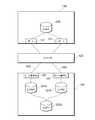
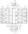
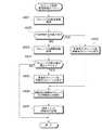
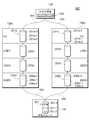
以下、各図を参照しながら本発明の実施形態について説明する。まず、図1を参照しながら本実施形態に関わる論理ユニット移動処理の原理を説明する。本実施形態に関わる計算機システム500は、ホスト計算機100と、複数のストレージシステム130a,130bと、外部ストレージシステム150とを備える。 Embodiments of the present invention will be described below with reference to the drawings. First, the principle of logical unit migration processing according to this embodiment will be described with reference to FIG. A
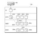
ストレージシステム130aは、一つ以上の論理ユニット(LU)201aを備える。この論理ユニット201aには、LUN(Logical Unit Number)がアサインされる。論理ユニット201aは、論理的な記憶領域として、ホスト計算機100に提供される。ホスト計算機100は、論理ユニット201aへのデータの書込みや、論理ユニット201aからのデータの読み出しを行うことができる。論理ユニット201aの下層には、複数の中間記憶階層(LDEV/VDEV/EDEV)が設けられている。この中間記憶階層は、論理ユニット201aと外部ボリューム301との間を対応つけるための論理的な記憶資源である。ホスト計算機100からのアクセスは、論理ユニット201aから中間記憶階層を介して外部ボリューム301に伝えられる。 The
ストレージシステム130a内の中間記憶階層には、例えば、論理デバイス(LDEV)202a、仮想デバイス(VDEV)203a、及び拡張デバイス(EDEV)206aを含めることができる。これらの各デバイスは必ずしも必須ではなく、一部のデバイスを省略してもよい。また、これらの各デバイスに加えて他のデバイス(例えば、後述するデバイスグループ(DEVGr)など)を更に含めてもよい(図3参照)。 The intermediate storage hierarchy in the
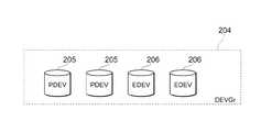
尚、図3に示すように、ストレージシステム130が物理デバイス(PDEV)205を有する場合には、物理デバイス205と拡張デバイス206とは、共に同一の中間記憶階層に属する。 As shown in FIG. 3, when the
説明の便宜上、論理ユニットが属する記憶階層を「LDEV階層」と称する場合がある。同様に、論理デバイスが属する記憶階層を「LDEV階層」と称し、仮想デバイスが属する記憶階層を「VDEV階層」と称し、物理デバイス及び/又は拡張デバイスが属する記憶階層を「PDEV/EDEV階層」と称する場合がある。 For convenience of explanation, a storage hierarchy to which a logical unit belongs may be referred to as an “LDEV hierarchy”. Similarly, a storage hierarchy to which a logical device belongs is referred to as an “LDEV hierarchy”, a storage hierarchy to which a virtual device belongs is referred to as a “VDEV hierarchy”, and a storage hierarchy to which a physical device and / or an expansion device belongs is referred to as a “PDEV / EDEV hierarchy”. Sometimes called.
ストレージシステム130aは、パス401を介してホスト計算機100に接続するための一つ以上のポート131aと、ポート131aに割り当てられる論理ユニット201aと、論理ユニット201aにマッピングされる論理デバイス202aと、論理デバイス202aにマッピングされる仮想デバイス203aと、仮想デバイス203aにマッピングされる拡張デバイス206aとを備えている。ここで、「マッピング」とは、あるデバイスのアドレス空間と、他のデバイスのアドレス空間とを対応付けることをいう。本明細書において、あるデバイスを他のデバイスにマッピングすることは、あるデバイスを他のデバイスに対応付ける(又は割り当てる)ことと同義である。 The
ストレージシステム130aは、パス402を介して外部ストレージシステム150に接続している。外部ストレージシステム150は、ディスクドライブ等の実記憶領域を有する物理デバイス上に定義された外部ボリューム301を有する。 The
ここで、拡張デバイス206aは、ストレージシステム130aの外部に存在する記憶資源である外部ボリューム301を仮想化したものである。つまり、拡張デバイス206aは外部記憶資源を仮想化してなる記憶階層である。 Here, the
仮想デバイス203aは、上位記憶階層(例えば、LU/LDEV)と下位記憶階層(例えば、DEVGr/EDEV)とを接続する記憶階層である。下位記憶階層が物理デバイスである場合には、仮想デバイス203aは、例えば、複数の物理デバイスのそれぞれが提供する記憶領域をRAID構成してなる記憶階層である。一方、下位記憶階層が拡張デバイス206aである場合には、仮想デバイス203aは、例えば、複数の拡張デバイス206aのそれぞれの記憶領域の全部又は一部を集合してなる記憶領域、或いは拡張デバイス206aの記憶領域の一部を抜き出してなる記憶領域である。 The
論理デバイス202aは、例えば、複数の仮想デバイス203aのそれぞれの記憶領域の全部又は一部を集合してなる記憶領域、或いは仮想デバイス203aの記憶領域の一部を抜き出してなる記憶領域である。ホスト計算機100がオープン系システムの場合、ホスト計算機100は、論理デバイス202aを一つの物理的なデバイスとして認識し、LUNや論理ブロックアドレスを指定することにより、所望の論理デバイス202aにアクセスする。ホスト計算機100がメインフレーム系システムの場合、ホスト計算機100は、論理デバイス202aを直接認識する。 The
論理ユニット201aは、外部ボリューム301を仮想化したものであって、且つホスト計算機100が認識する論理的な記憶領域である。例えば、ホスト計算機100がUNIX(登録商標)系システムである場合には、論理ユニット201aは、デバイスファイル(Device File)に対応付けられる。一方、ホスト計算機100がWindows(登録商標)系システムである場合には、論理ユニット201aは、ドライブレター(ドライブ名)に対応付けられる。論理ユニット201aには、固有のLUN(Logical Unit Number)がアサインされる。 The
論理ユニット移動処理を説明するための便宜上、論理ユニット201aと論理デバイス202aとの対応関係は一対一とし、論理デバイス202aと仮想デバイス203aとの対応関係は一対一とし、仮想デバイス203aと拡張デバイス206aとの対応関係は一対一とし、拡張デバイス206aと外部ボリューム301との対応関係は一対一とする。かかる対応関係の下では、ホスト計算機100が認識する論理ユニット201aの記憶容量は、外部ボリューム301の記憶容量に等しい。 For convenience in explaining the logical unit migration processing, the correspondence between the
一方、ストレージシステム130bは、ストレージシステム130aと同様に階層化された複数の記憶階層を有している。ストレージシステム130bは、パス403を介してホスト計算機100に接続するための一つ以上のポート131bと、ポート131bに割り当てられる論理ユニット201bと、論理ユニット201bにマッピングされる論理デバイス202bと、論理デバイス202bにマッピングされる仮想デバイス203bと、仮想デバイス203bにマッピングされる拡張デバイス206c,206bとを備えている。 On the other hand, the
論理ユニット移動処理を説明するための便宜上、論理ユニット201bと論理デバイス202bとの対応関係は一対一とし、論理デバイス202bと仮想デバイス203bとの対応関係は一対一とし、仮想デバイス203bと拡張デバイス206cとの対応関係は一対一とし、仮想デバイス203bと拡張デバイス206bとの対応関係は一対一とし、拡張デバイス206cと論理ユニット201aとの対応関係は一対一とし、拡張デバイス206bと外部ボリューム301との対応関係は一対一とする。また、拡張デバイス206cと拡張デバイス206bとは、同一の記憶容量を有しており、拡張デバイス206cと拡張デバイス206bとのうち何れか一方が択一的に仮想デバイス203bにマッピングされるものとする。 For convenience of explaining the logical unit migration processing, the correspondence between the
次に、ストレージシステム130a(移動元ストレージ)内の論理ユニット201a(移動元論理ユニット)にあるデータをストレージシステム130b(移動先ストレージ)内の論理ユニット201b(移動先論理ユニット)に移動する処理について概説する。論理ユニット移動処理は、下記の(1)〜(9)の処理手順を含む。 Next, a process of moving data in the
(1)ストレージシステム130bは、外部ボリューム301と、ストレージシステム130bとの間を外部接続するためのパス405を定義し、外部ボリューム301を仮想化するための拡張デバイス206bをストレージシステム130b内に作成する。(1) The
(2)ストレージシステム130bは、外部ボリューム301の記憶容量と同一の記憶容量を有する仮想デバイス203bをストレージシステム130b内に作成する。(2) The
(3)ストレージシステム130bは、論理ユニット201aとストレージシステム130bとの間を外部接続するためのパス404を定義し、論理ユニット201aを仮想化するための拡張デバイス206cをストレージシステム130b内に作成する。(3) The
(4)ストレージシステム130bは、拡張デバイス206cを仮想デバイス203bにマッピングする。(4) The
(5)ストレージシステム130bは、論理デバイス202aの論理構成と同一の論理構成を有する論理デバイス202bをストレージシステム130b内に作成する。仮想デバイス203bは、論理デバイス202bにマッピングされる。(5) The
(6)ストレージシステム130bは、論理ユニット201aの論理構成と同一の論理構成を有する論理ユニット201bをストレージシステム130b内に作成し、ホスト計算機100と論理ユニット201bとを接続するためのパス403を定義する。論理デバイス202bは、論理ユニット201bにマッピングされる。(6) The
(7)ホスト計算機100は、外部ボリューム301にアクセスするための経路として、パス401からパス403に切り替える。このとき、パス401を削除する等して、ホスト計算機100から論理ユニット201aへのアクセスを禁止する。尚、パス401からパス403へのパス切り替えは、ストレージシステム130a,130b,又は管理サーバ110等が行っても良い。また、必ずしもパス401を削除する必要はなく、例えば、パス401をパス403の交替パス(例えば、システム障害時に使用するためのパス)として設定し、パス401の状態を無効としたまま、パス401を残しても良い。(7) The
上記の処理により、論理ユニット201bは、論理ユニット201aを仮想化したものであるだけでなく、外部ボリューム301をも仮想化したものでもあるので、論理ユニット移動処理中における、ホスト計算機100から論理ユニット201aへのデータ入出力経路は、パス403→ストレージシステム130b内の記憶階層(LU/LDEV/VDEV/EDEV)→パス404→ストレージシステム130a内の記憶階層(LU/LDEV/VDEV/EDEV)→パス402→外部ボリューム301となる。 With the above processing, the
尚、論理ユニット移動処理に関与するストレージシステム130a,130bに暗号化機能が搭載されている場合、二つのストレージシステム130a,130bの暗号化機能がオンに設定されていると、外部ボリューム301に書き込まれたデータを復号できなくなる場合がある。このような場合には、ストレージシステム130bの暗号化機能をオフに設定し、ストレージシステム130aの暗号化機能をオンに設定する。つまり、ストレージシステム130bによって、拡張デバイス206cに書き込まれるデータは暗号化されず、ストレージシステム130aによって拡張デバイス206aに書き込まれるデータは暗号化されない。暗号化機能をこのように設定することで、外部ボリューム301に書き込まれるデータが暗号化される回数を一回のみにすることができるので、外部ボリューム301に書き込まれたデータを復号することができる。 If the encryption function is installed in the
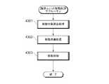
(8)ストレージシステム130aは、ストレージシステム130aのディスクキャッシュに蓄積されている全てのダーティデータを外部ボリューム301にデステージするためにストレージシステム130aの動作モードをキャッシュスルーモード(ライトスルーモード)に設定する。ダーティデータとは、ディスクキャッシュから外部ボリューム301にデステージされていない未反映データをいう。キャッシュスルーモードとは、ホスト計算機100からのデータ書き込み要求を受けてデータをディスクキャッシュに格納し、更にデバイス(内部デバイス又は外部デバイス)にもそのデータを書き込んでから、ホスト計算機100にデータ更新完了報告をする動作をいう。尚、ストレージシステム130aは、自発的に動作モードをキャッシュスルーモードに設定してもよく、或いは外部(例えば、ストレージシステム130b、ホスト計算機100、又は後述する管理サーバ110など)からの指示に基づいて、動作モードをキャッシュスルーモードに設定してもよい。(8) The
(9)ストレージシステム130aのディスクキャッシュに蓄積されているダーティデータの全てを外部ボリューム301にデステージできたならば、ストレージシステム130bは、拡張デバイス206cと仮想デバイス203bとの間のマッピング関係を解除し、拡張デバイス206bを仮想デバイス203bにマッピングする。更に、ストレージシステム130bは、パス404を削除する。(9) If all of the dirty data stored in the disk cache of the
かかる方法によれば、ホスト計算機100から論理ユニット201aへのデータ入出力処理を継続させたまま論理ユニット201aを移動させることができる。これにより、ホスト計算機100からのI/O要求に起因する複数のストレージシステム130間の負荷変動の発生に応じて外部ボリュームへのI/O処理担当を複数のストレージシステム130a,130b間で切り替えることで、計算機システム500の負荷分散を実現できる。しかも、ストレージシステム130a、130bのうち移動元ストレージの動作モードをキャッシュスルーモードに設定し、移動先ストレージの動作モードをライトアフタモードに設定することによりディスクキャッシュを用いた非同期ライト処理が可能となるので、論理ユニット移動処理に伴うストレージシステム130aの性能低下を抑制できる。 According to this method, the
尚、移動先のストレージシステム130bの動作モードをキャッシュスルーモードに設定しても、論理ユニット201aを移動させることはできるが、移動元のストレージシステム130a内に蓄積されているダーティデータの全てを外部ボリューム301にデステージしない限り、論理ユニット201aの移動処理は完了しない。そこで、論理ユニット201aの移動処理時間を短くするには、移動元のストレージシステム130aの動作モードをキャッシュスルーモードに設定するのが好ましい。 Even if the operation mode of the migration
また、図1に示すシステム構成では、それぞれのストレージシステム130a,130bは、外部ボリューム301を仮想化してなる拡張デバイス206を有するが、内部デバイス(物理デバイス)を有しない。本発明に関わる論理ユニット移動処理は、図1に示すようなシステム構成への適用に限られるものではなく、例えば、外部ボリューム仮想化機能を有しないストレージシステム130a,130bが内蔵するディスク装置等の物理デバイスによって提供される論理ユニットを移動させる処理にも適用できる。 Further, in the system configuration shown in FIG. 1, each
上記の論理ユニット移動処理の説明においては、説明の便宜上、それぞれの中間記憶階層相互間のマッピング関係を一対一とする場合を例示したが、それぞれの中間記憶階層相互間のマッピング関係は必ずしも一対一の関係に限られるものではない。例えば、それぞれの中間記憶階層相互間のマッピング関係として、例えば、CVS(Custom Volume Size)、LUSE(LU Size Expansion)、外部ボリュームRAID、VMA(Volume Management Area)付きボリューム、メインフレームボリューム、VDEV連結、VDEV離散、AOU(Allocation on Use)、スナップショットなどの各種のバリエーションが考えられる。詳細については、後述の実施例において説明する(図4乃至図22参照)。 In the above description of the logical unit migration processing, for convenience of explanation, the case where the mapping relationship between the respective intermediate storage hierarchies is set to be one-to-one is illustrated. It is not limited to this relationship. For example, as a mapping relationship between the respective intermediate storage tiers, for example, CVS (Custom Volume Size), LUSE (LU Size Expansion), external volume RAID, volume with VMA (Volume Management Area), mainframe volume, VDEV connection, Various variations such as VDEV discrete, AOU (Allocation on Use), and snapshots are conceivable. Details will be described in an embodiment described later (see FIGS. 4 to 22).
図2は本実施例に関わる計算機システム500のネットワーク構成を示す。
計算機システム500は、複数のホスト計算機100a,100b、一つ以上の管理サーバ110、一つ以上のファイバチャネルスイッチ120、複数のストレージシステム130a,130b、複数の管理端末140a,140b、及び複数の外部ストレージシステム150a,150bを備える。以下の説明では、ホスト計算機100a,100bを区別しないときには、ホスト計算機100と総称する。ストレージシステム130a,130bを区別しないときには、ストレージシステム130と総称する。管理端末140a,140bを区別しないときには、管理端末140と総称する。外部ストレージシステム150a,150bを区別しないときには、ストレージシステム150と総称する。FIG. 2 shows a network configuration of a
The
ホスト計算機100、ストレージシステム130、及び外部ストレージシステム150は、それぞれポート107,131,151を介してファイバチャネルスイッチ120のポート121に接続される。また、ホスト計算機100、ストレージシステム130、外部ストレージシステム150、及びファイバチャネルスイッチ120は、それぞれインタフェース制御部106、138,157,123から、IPネットワーク175を介して管理サーバ110に接続される。管理サーバ110は、これらのネットワークノード(ホスト計算機100、ストレージシステム130、外部ストレージシステム150、及びファイバチャネルスイッチ120)を管理する。 The
尚、本実施例では、ストレージシステム130は、管理端末140を介して管理サーバ110に接続するネットワーク構成を有するものとするが、ストレージシステム130がIPネットワーク175に直接接続するネットワーク構成であってもよい。 In this embodiment, the
ホスト計算機100は、CPU101、メモリ102、記憶装置103、入力装置104、ディスプレイ105、インタフェース制御部106、及びポート107を有する。記憶装置103は、例えば、ディスク装置、光磁気ディスク装置等である。ホスト計算機100は、記憶装置103に格納されたオペレーティングシステムやアプリケーションプログラムなどのソフトウェアをメモリ102に読み上げ、CPU101によりそのソフトウェアを読み出して実行させることで、情報処理を実行する。入力装置104は、キーボード又はマウス等である。ホスト計算機100は、入出力装置104を介してホスト管理者などからの入力を受け付け、ディスプレイ105に情報処理結果等を表示する。インタフェース制御部106は、IPネットワーク175に接続するためのLANアダプタ等である。ポート107は、ストレージシステム130に接続するためのホストバスアダプタ等である。 The
管理サーバ110は、CPU111、メモリ112、記憶装置113、入力装置114、ディスプレイ115、及びインタフェース制御部116を有する。記憶装置113は、例えば、ディスク装置、光磁気ディスク装置等である。管理サーバ110は、記憶装置113に格納されたストレージ管理ソフトウェアなどをメモリ112に読み上げ、CPU111によりそのストレージ管理ソフトウェアを読み出して実行することにより、計算機システム500全体を保守管理する。CPU111によってストレージ管理ソフトウェアが実行されると、管理サーバ110は、インタフェース制御部116からIPネットワーク175を介して、計算機システム500内の各ネットワークノードから構成情報、リソース利用率、性能監視情報、障害ログなどを収集する。そして、管理サーバ110は、収集したそれらの情報をディスプレイ115等の出力装置に出力して、ストレージ管理者に提示する。また、管理サーバ110は、キーボードやマウス等の入力装置114を介してストレージ管理者から保守管理に関する指示を受け付け、その指示をネットワークノードに送信する。 The
ストレージシステム130は、ストレージネットワークに接続するための一つ以上のポート131、ディスク装置137へのデータ入出力処理を制御するための一つ以上の制御プロセッサ132、それぞれの制御プロセッサ132のワークエリアとして機能する一つ以上のメモリ133、ディスク装置137に入出力されるデータを一時的に格納するための一つ以上のディスクキャッシュ134、ストレージシステム130の構成情報等を格納するための一つ以上の制御メモリ135、ディスク装置137に接続するためのインタフェースとして機能する一つ以上のポート136、データを格納するためのディスク装置137を有する。 The
制御プロセッサ132は、ポート131を介してホスト計算機100から受信した入出力要求に含まれる情報(ポートID、及びLUN)基づいて、アクセス先の論理ユニットを特定する。アクセス先の論理ユニットがディスク装置137(内部デバイス)に対応しているならば、制御プロセッサ132は、ディスク装置137へのデータ入出力を制御する。アクセス先の論理ユニットが外部ストレージシステム150(外部デバイス)に対応しているならば、制御プロセッサ132は、外部ストレージシステム150へのデータ入出力を制御する。 The
尚、本実施例では、ポート131として、SCSI(Small Computer System Interface)を上位プロトコルとするファイバチャネルインタフェースに対応するポートを想定しているが、ポート131は、SCSIを上位プロトコルとするIPネットワークインタフェースに対応するポートであってもよい。 In this embodiment, the
ストレージシステム130は、次のような記憶階層を有する。複数のディスク装置137によるディスクアレイが構成され、このディスクアレイは、制御プロセッサ132によって物理デバイスとして管理される。更に、制御プロセッサ132は、ストレージシステム130内に搭載した物理デバイスに論理デバイスを割り当てる(つまり、制御プロセッサ132は、物理デバイスと論理デバイスとを対応付ける。)。論理デバイスは、ストレージシステム130内で管理され、そのLDEV番号は、ストレージシステム130毎に独立に管理される。 The
論理デバイスは、各ポート131に割り当てられたLUNに対応付けられ、ストレージシステム130内のデバイスとしてホスト計算機100に提供される。即ち、ホスト計算機100が認識するのは、ストレージシステム130内の論理デバイスであり、ホスト計算機100は、ポート131に割り当てられた論理デバイスを識別するためのLUNを用いて、ストレージシステム130に格納されているデータにアクセスする。 The logical device is associated with the LUN assigned to each
尚、本実施例では、制御プロセッサ132は、外部ストレージ150内の論理デバイスを外部デバイスとして管理し、ストレージシステム130内のデバイス(内部デバイス)として仮想化する。つまり、ストレージシステム130によって管理される外部デバイスは、仮想デバイスである。外部ストレージ接続技術を用いて、ストレージシステム130内に取り込まれた外部デバイスは、ストレージシステム130内の物理デバイスと同様にストレージシステム130内の論理デバイスとして管理される。 In this embodiment, the
以上のような記憶階層を実現するため、制御プロセッサ132は、ストレージシステム130内における論理デバイス、物理デバイス、及びディスク装置137と、外部ストレージシステム150内における論理デバイス、及びディスク装置156との対応関係を管理する。そして、制御プロセッサ132は、ホスト計算機100からのI/O要求を、ストレージシステム130内のディスク装置137へのアクセス要求、又は外部ストレージシステム150内のディスク装置156へのアクセス要求に変換する。 In order to realize the storage hierarchy as described above, the
尚、前述の通り、本実施例におけるストレージシステム130は、複数のディスク装置137の記憶領域をまとめて一つ以上の物理デバイスを定義し(つまり、複数のディスク装置137の記憶領域をまとめて一つ以上の物理デバイスに対応付ける。)、一つの物理デバイスに一つの論理デバイスを割り当てて、その記憶領域をホスト計算機100に提供する。個々のディスク装置137をそれぞれ一つの物理デバイスに対応付けてもよい。 As described above, the
制御プロセッサ132は、デバイスへのデータ入出力処理だけでなく、ボリューム間のデータ複製やデータ再配置などを制御する。制御プロセッサ132は、インタフェース制御部138を介して管理端末140に接続しており、ストレージ管理者によって管理端末140に入力された構成変更指示を受信し、ストレージシステム130の構成変更を行うこともできる。 The
ディスクキャッシュ134は、ホスト計算機100とディスク装置137との間で入出力されるデータを一時的に格納する。ストレージシステム130がホスト計算機100から受信したデータをディスクキャッシュ134に格納し、ライト完了報告をホスト計算機100に返信してから、その後、データをディスク装置137にデステージする処理は、ライトアフタ処理と称される。 The
ストレージシステム130がライトアフタ処理を行うように構成されている場合、ディスクキャッシュ134に格納されているデータがディスク装置137に書き込まれる前に消失することを防止するために、ディスクキャッシュ134を電源バックアップしたり、或いはディスクキャッシュ134を二重化したりする等して、耐障害性を向上させるのが好ましい。 When the
制御メモリ135には、ストレージシステム130の構成情報(例えば、デバイス間の対応関係を管理するためのマッピング情報、キャッシュスルーモードの設定情報など)が格納されている。制御メモリ135に格納されている構成情報が消失すると、制御プロセッサ132は、ディスク装置137へのアクセスできなくなるので、制御メモリ135を電源バックアップしたり、或いは制御メモリ135を二重化したりする等して、耐障害性を向上させるのが好ましい。 The
管理端末140は、インタフェース制御部141、CPU142、メモリ143、記憶装置144、入力装置145、ディスプレイ146、及びインタフェース制御部147を有する。インタフェース制御部141は、ストレージシステム130に接続するための通信インタフェースである。記憶装置144は、例えば、ディスク装置又は光磁気ディスク装置等である。入力装置145は、キーボード又はマウス等である。ディスプレイ146は、ストレージ管理用のユーザインターフェース環境を提供するものであり、例えば、ストレージシステム130の構成情報や管理情報などを表示する。CPU142は、記憶装置144に格納されているストレージ管理プログラムをメモリ143に読み出して実行することにより、構成情報の参照、構成変更の変更、特定機能の動作指示などを行う。 The management terminal 140 includes an
尚、本実例では、管理端末140を介さずに、ストレージシステム130を管理サーバ110に直接接続し、管理サーバ110上で動作する管理ソフトウェアによって、ストレージシステム130を管理するネットワーク構成を採用してもよい。 In this example, a network configuration may be adopted in which the
外部ストレージシステム150は、ファイバチャネルスイッチ120を介してストレージ130のポート131に接続するための一つ以上のポート151、ディスク装置156へのデータ入出力処理を制御するための一つ以上の制御プロセッサ152、それぞれの制御プロセッサ152のワークエリアとして機能する一つ以上のメモリ153、ディスク装置156に入出力されるデータを一時的に格納するための一つ以上のディスクキャッシュ154、制御プロセッサ152がディスク装置156に接続するためのインタフェースとして機能する一つ以上のポート155、データを格納するための一つ以上のディスクドライブ156、IPネットワークに接続するためのインタフェースとして機能するインタフェース制御部157を有する。 The
尚、本実施例では、ストレージシステム130に装備されているポート131と、外部ストレージシステム150に装備されているポート151とをファイバチャネルスイッチ120を介して接続するネットワーク構成を採用しているので、ホスト計算機100からの外部ストレージシステム150への直接的なアクセスを抑止するために、ファイバチャネルスイッチ120にゾーニングを設定することが望ましい。ストレージネットワーク上に必ずしもファイバチャネルスイッチ120を設置する必要はなく、例えば、ストレージシステムに装備されているポート131と、外部ストレージシステム150に装備されているポート151とを直接接続するようなネットワーク構成を採用してもよい。 In this embodiment, since the network configuration in which the
図3は本実施例に関わるストレージシステム130内に構築される記憶階層を示す。図1乃至図2に示す符号と同一符号の論理資源又は物理資源は、同一のものを示すものとしてその詳細な説明を省略する。 FIG. 3 shows a storage hierarchy constructed in the
ホスト計算機100は、リンクマネージャ108、及びRAIDマネージ109を備える。リンクマネージャ108は、ストレージシステム130へのアクセス経路を切り替えるためのソフトウェアプログラムである。RAIDマネージャ109は、ストレージシステム130の記憶資源を管理するためのストレージ管理ソフトウェアであり、ストレージシステム130に各種の指示(例えば、論理ユニット移動指示)を与える。 The
ストレージシステム130に装備されているあるポート131は、ストレージネットワーク510を介してホスト計算機100に接続する一方、他のポート131は、ストレージネットワーク510を介して外部ストレージシステム150に接続している。ストレージネットワーク510は、一つ以上のファイバチャネルスイッチ120を含むFC−SAN(Fibre Channel Storage Area Network)等のネットワークである。 One
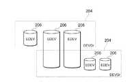
ストレージシステム130は、論理ユニット201、論理デバイス202、仮想デバイス203、デバイスグループ204、物理デバイス205、及び拡張デバイス206から成る記憶階層を有する。デバイスグループ204は、例えば、複数の物理デバイス205又は拡張デバイス206のうち何れか一方又は両者のそれぞれの記憶領域の全部又は一部を集合してなる記憶領域、或いは物理デバイス205又は拡張デバイス206のうち何れか一方又は両者の記憶領域の一部を抜き出してなる記憶領域である。 The
尚、物理デバイス205は、ストレージシステム130が有するディスク装置137の記憶領域(内部デバイス)を仮想化したものであるのに対し、拡張デバイス206は、外部ストレージシステム150が有するディスク装置156の記憶領域(外部デバイス)を仮想化したものである点で異なるが、両者は共に実デバイスを仮想化したものである点では共通なので、同一階層(最下層)に属している。 The
ストレージシステム130は、ポート131に割り当てられるCMD(Command Device)207を備える。CMD207は、ホスト計算機100とストレージシステム130との間でコマンドやステータスを受け渡すために用いられる論理ユニットである。ホスト計算機100からストレージシステム130に送信されるコマンドは、CMD207に書き込まれる。ストレージシステム130は、CMD207に書き込まれるコマンドに対応する処理を実行し、その実行結果をステータスとしてCMD207に書き込む。ホスト計算機100は、CMD207に書き込まれるステータスを読み出して確認し、次に実行すべきコマンドをCMD207に書き込む。このようにして、ホスト計算機100は、ストレージシステム130に各種の指示を与えることができる。 The
ホスト計算機100がストレージシステム130に与える指示内容としては、例えば、論理ユニット単位でのデバイス移動指示(論理ユニット移動指示)又は論理デバイス単位でのデバイス移動指示(論理デバイス移動指示)がある。論理ユニット移動処理の概要については、上述した通りである。移動元の論理ユニット201がLUSE構成を有している場合には、ホスト計算機100はストレージシステム130に論理デバイス移動指示を与えることができる。LUSE構成を有する論理ユニット201では、複数の論理デバイス202が一つの論理ユニット201にマッピングされているので(図5参照)、複数の論理デバイス202のうち一つの論理デバイス202(例えば、論理ユニット201の先頭アドレスに割り当てられている論理デバイス202)を指定することで、その論理ユニット201にマッピングされている他の全ての論理デバイス202も移動対象として指定することもできる。 Examples of the instruction content that the
尚、ストレージシステム130は、所定の条件(例えば、ストレージシステム130に障害が発生した場合、又はストレージシステム130の性能が低下した場合など)が満たされたことを契機として、自発的に(ホスト計算機100からの指示を待つことなく)、論理ユニット移動処理を実行してもよい。ストレージシステム130に障害が発生した場合又はストレージシステム130の性能が低下した場合を契機として、論理ユニットを移動させる処理の概要については、後述する。 Note that the
また、管理サーバ110がIPネットワーク175及び管理端末140を経由して、ストレージシステム130に論理ユニット移動指示を与えてもよい。つまり、ホスト計算機100からインバンド経由(ストレージネットワーク経由)でストレージシステム130に論理ユニット移動指示を与えてもよく、或いは管理サーバ110からアウトバンド経由(IPネットワーク経由)でストレージシステム130に論理ユニット移動指示を与えてもよい。 Further, the
次に、図4乃至図22を参照しながら各記憶階層相互間のマッピング関係のバリエーションについて説明を加える。 Next, a variation of the mapping relationship between the storage hierarchies will be described with reference to FIGS.
(1)CVS
図4に示すように一つの仮想デバイス203を複数のVDEV領域203−1,203−2,203−3に分割し、それぞれのVDEV領域203−1,203−2,203−3に一つの論理デバイス202を割り当てるマッピング関係をCVSと称する。それぞれのVDEV領域203−1,203−2,203−3のサイズは、必ずしも同一である必要はない。(1) CVS
As shown in FIG. 4, one
(2)LUSE
図5に示すように複数の論理デバイス202の記憶領域を集めて一つの論理ユニット201に割り当てるマッピング関係をLUSEと称する。(2) LUSE
As shown in FIG. 5, a mapping relationship in which storage areas of a plurality of
(3)外部ボリュームRAID
図6に示すようにRAID構成された拡張デバイス206をデバイスグループ204に割り当てるマッピング関係を外部ボリュームRAIDと称する。例えば、RAID1によってRAID構成された複数の拡張デバイス206のうち一方の拡張デバイス206は、データディスクに対応し、他方の拡張デバイス206は、ミラーディスクに対応する。(3) External volume RAID
As shown in FIG. 6, the mapping relationship for assigning the RAID-configured
(4)VMA付きボリューム
図7はVMA付きボリュームを示す。VMA付きボリュームは、オープンシステム系のシステムに用いられる論理デバイス202である。この論理デバイス202は、ユーザデータを格納するためのユーザ領域202−1と、管理情報を格納するための管理領域202−2とを含む。管理情報には、例えば、VMA付きボリュームのアクセス属性が含まれる。アクセス属性は、リード/ライト可能、リードオンリ、リード/ライト不可、リードキャパシティゼロ、インクエリ(Inquiry)抑止、セカンダリボリュームディセーブル(S-VOL disable)などの情報を含む。ユーザ領域202−1は、ホスト計算機100が認識することが可能であり、しかも論理ユニット201に割り当てられるのに対して、管理領域202−2は、ホスト計算機100が認識することはできず、しかも論理ユニット201に割り当てられることもない。(4) Volume with VMA FIG. 7 shows a volume with VMA. The volume with VMA is a
(5)メインフレームボリューム
図8はメインフレームボリュームを示す。メインフレームボリュームは、メインフレーム系のシステムに用いられる論理デバイス202である。この論理デバイス202は、ユーザデータを格納するためのユーザ領域202−1と、管理情報を格納するための管理領域202−3とを含む。管理情報には、例えば、メインフレームボリュームのアクセス属性などが含まれる。ユーザ領域202−1は、ホスト計算機100が認識することが可能であり、しかも論理ユニット201に割り当てられるのに対して、管理領域202−3は、ホスト計算機100が認識することはできず、しかも論理ユニット201に割り当てられることもない。(5) Mainframe volume FIG. 8 shows a mainframe volume. The main frame volume is a
(6)VDEV連結
図9に示すように複数の仮想デバイス203の記憶領域を集めて一つの論理デバイス202に割り当てるマッピング関係をVDEV連結と称する。(6) VDEV Concatenation As shown in FIG. 9, a mapping relationship in which storage areas of a plurality of
(7)VDEV離散(基本形)
図10に示すように複数のデバイスグループ204の記憶領域を集めて一つの仮想デバイス203に割り当てるマッピング関係をVDEV離散と称する。VDEV離散のマッピング関係には、後述する変形例1〜2が含まれる。(7) VDEV discrete (basic form)
As shown in FIG. 10, a mapping relationship in which storage areas of a plurality of
(8)VDEV離散(変形例1)
VDEV離散の一つの変形例として、例えば、図11に示すように一つのデバイスグループ204を複数の記憶領域に分割し、分割されたそれぞれの記憶領域に一つの仮想デバイス203を割り当ててもよい。(8) VDEV discrete (Modification 1)
As a modification of the VDEV discrete, for example, as shown in FIG. 11, one
(9)VDEV離散(変形例2)
VDEV離散の他の一つの変形例として、例えば、図12に示すように複数のデバイスグループ204のそれぞれを複数の記憶領域に分割し、分割されたそれぞれの記憶領域を複数の仮想デバイス203に割り当ててもよい。(9) VDEV discrete (Modification 2)
As another modification of the VDEV discrete, for example, as shown in FIG. 12, each of the plurality of
(10)DEVGr/EDEV
デバイスグループ204と拡張デバイス206との間のマッピング関係については、例えば、図13に示すように、複数の拡張デバイス206のそれぞれの記憶領域の全部又は一部を集めて一つのデバイスグループ204に割り当ててもよい。拡張デバイス206の中には、デバイスグループ204に割り当てられない記憶領域を含むものが存在してもよい。また例えば、図14に示すように、複数の拡張デバイス206のそれぞれの記憶領域の全部又は一部を集めて複数のデバイスグループ204に割り当ててもよい。拡張デバイス206の中には、何れのデバイスグループ204にも割り当てられない記憶領域を含むものが存在してもよい。また例えば、図15に示すように、複数のデバイスグループ204に割り当てられる拡張デバイス206や、一部のデバイスグループ204にのみ割り当てられる拡張デバイス206が存在してもよい。(10) DEVGr / EDEV
As for the mapping relationship between the
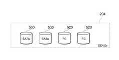
(11)異種メディア混載RAID
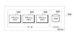
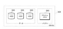
図16に示すように、一つのデバイスグループ204の記憶領域に異種デバイス(例えば、物理デバイス205及び拡張デバイス206)が混在した形態で割り当ててもよい。また例えば、図17に示すように、一つのデバイスグループ204の記憶領域に異種ディスクドライブ(例えば、FCディスクドライブ520及びSATAディスクドライブ530)が混在した形態で割り当ててもよい。また例えば、図18乃至図20に示すように一つのデバイスグループ204の記憶領域にフラッシュメモリ540及びディスクドライブ550が混在した形態で割り当ててもよい。(11) RAID mixed with different media
As illustrated in FIG. 16, the storage areas of one
図18では、複数のフラッシュメモリ540と、複数のディスクドライブ550とによってRAID0/1構成のデバイスグループ204が構成されている。複数のフラッシュメモリ540によってデータボリュームが構成され、複数のディスクドライブ550によってミラーボリュームが構成されている。このようなドライブ構成においては、ランダムリード時には、フラッシュメモリ540からデータが読み出される。シーケンシャルリード時には、フラッシュメモリ540とディスクドライブ550のそれぞれからデータが読み出される。ライト時には、フラッシュメモリ540とディスクドライブ550のそれぞれにデータが書き込まれる。このようなドライブ構成によればフラッシュメモリ540の高速性を活かしつつ、フラッシュメモリ540のみのRAIDよりも低コストである。 In FIG. 18, a plurality of
図19では、三つのフラッシュメモリ540と一つのディスクドライブ550とによってRAID4構成のデバイスグループ204が構成されている。フラッシュメモリ540は、データを格納し、ディスクドライブ550は、パリティデータを格納する。このようなドライブ構成においては、書き込み寿命のあるフラッシュメモリ540を、アクセス数の多いパリティドライブに使用しないことにより、フラッシュメモリ540の使用期間を延ばすことができる。 In FIG. 19, three
図20では、一つのフラッシュメモリ540と三つのディスクドライブ550とによってRAID4構成のデバイスグループ204が構成されている。フラッシュメモリ540は、データを格納し、ディスクドライブ550は、パリティデータを格納する。このようなドライブ構成においては、アクセス数の多いパリティドライブとして、フラッシュメモリ540を使用することにより、書き込み性能を向上させることができる。 In FIG. 20, one
(12)AOU
図21はストレージシステム130内における、AOUと称される記憶階層相互間のマッピング関係を示す。LU階層には、論理ユニット201が属している。LDEV階層には、AOUボリューム202cと複数のプールボリューム202dが属している。VDEV階層には、複数のプールボリューム203cが属している。PDEV/EDEV階層には、複数の拡張デバイス206eが属している。ホスト計算機100が認識する論理ユニット201には、AOUボリューム202cが割り当てられている。AOUボリューム202cには、複数のプールボリューム203cのそれぞれの記憶領域の一部が割り当てられている。AOUボリューム202cには、プールボリューム203cの記憶領域を動的に割り当てることが可能であり、AOUボリューム202cの容量を自在に増減することができる。複数のプールボリューム203cのそれぞれの記憶領域には、複数の拡張デバイス206eのそれぞれの記憶領域が割り当てられている。尚、PDEV/EDEV階層には、拡張デバイス206eに替えて物理デバイスを配置してもよい。(12) AOU
FIG. 21 shows a mapping relationship between storage tiers called AOU in the
(13)スナップショット
図22はスナップショット機能を備えるストレージシステム130内における記憶階層相互間のマッピング関係を示す。LU階層には、論理ユニット201が属している。LDEV階層には、プライマリボリューム202e、セカンダリボリューム202f、複数のプールボリューム202gが属している。VDEV階層には、仮想デバイス203d、複数のプールボリューム203eが属している。PDEV/EDEV階層には、拡張デバイス206f,206gが属している。論理ユニット201には、論理デバイス202eが割り当てられている。論理デバイス202eには、仮想デバイス203dが割り当てられている。仮想デバイス203dには、拡張デバイス206fが割り当てられている。セカンダリボリューム202fは、ある時刻にプライマリボリューム202eに格納されているデータと、ある時刻以降にプライマリボリューム202eからプールボリューム203eに退避されたデータとから、ある時刻におけるプライマリボリューム202eのデータイメージを復元するための仮想的な論理ボリュームである。(13) Snapshot FIG. 22 shows a mapping relationship between storage tiers in the
次に、図23を参照しながらホストグループについて説明を加える。ホストグループ番号#0のホストグループに属する複数のホスト計算機100a,100cは、何れも、ポート131の番号としてポート番号#0、及び論理ユニット201の番号としてLUN#0を指定することにより、論理デバイス番号#0の論理デバイス202hにアクセスできる。一方、ホストグループ番号#1のホストグループに属するホスト計算機100bは、ポート131の番号としてポート番号#0、及び論理ユニット201の番号としてLUN#0を指定することにより、論理デバイス番号#1の論理デバイス202iにアクセスできる。このように、あるホスト計算機100が同一のポート番号及び同一の論理ユニット番号を指定したとしても、そのホスト計算機100が所属するホストグループ番号によっては、アクセスできる論理デバイス202が異なる。 Next, the host group will be described with reference to FIG. Each of the plurality of
本実施形態に関わる論理ユニット移動処理においては、あるホストグループに属する一つのホスト計算機100が利用可能な論理ユニット201を他のストレージシステム130に移動させる場合には、そのホストグループに属する他のホスト計算機100についても同様の論理ユニット移動処理を実行させるものとする。 In the logical unit migration processing according to this embodiment, when a
次に、図24乃至図25を参照しながら交替パスについて説明を加える。図24に示すようにホスト計算機100からストレージシステム130内のある論理デバイス202jに接続するための複数のパス406,407が存在する場合にその複数のパス406,407のうち何れか一つのパス406を常用系パスとすると、他のパス407は交替パスとなる。交替パスは、待機系パスと称されることもある。ホスト計算機100は、ポート131の番号としてポート番号#0、及び論理ユニット201cの番号としてLUN#0を指定することにより、パス406を介して論理デバイス202jにアクセスできる。またホスト計算機100は、ポート131の番号としてポート番号#1、及び論理ユニット201dの番号としてLUN#0を指定することにより、パス407を介して論理デバイス202jにアクセスできる。リンクマネージャ108は、論理デバイス202jにアクセスするためのパスとして、パス406,407のうち何れか一方を選択する処理を実行する。論理ユニット201c,201dは、何れも同一の論理デバイス202jを仮想化したものであるので、一方の論理ユニット(例えば、論理ユニット201c)を他のストレージシステム130に移動させる場合には、他方の論理ユニット(例えば、論理ユニット201d)も他のストレージシステム130に移動させる必要がある。 Next, the alternate path will be described with reference to FIGS. As shown in FIG. 24, when there are a plurality of
図25に示すようにストレージシステム130から外部ストレージシステム150内のある論理デバイス202kに接続するための複数のパス408,409が存在する場合にその複数のパス408,409のうち何れか一つのパス408を常用系パスとすると、他のパス409は交替パスとなる。ストレージシステム130は、ポート151の番号としてポート番号#0、及び論理ユニット201eの番号としてLUN#0を指定することにより、パス408を介して論理デバイス202kにアクセスできる。また、ストレージシステム130は、ポート151の番号としてポート番号#1、及び論理ユニット201fの番号としてLUN#0を指定することにより、パス409を介して論理デバイス202kにアクセスできる。論理ユニット201e、201fは、何れも同一の論理デバイス202kを仮想化したものであるので、一方の論理ユニット(例えば、論理ユニット201e)を他のストレージシステム130に移動させる場合には、他方の論理ユニット(例えば、論理ユニット201f)も他のストレージシステム130に移動させる必要がある。 As shown in FIG. 25, when there are a plurality of
次に、図26乃至図33を参照しながら論理ユニット移動処理に用いられる各種の情報について説明を加える。 Next, various types of information used in the logical unit migration process will be described with reference to FIGS.
図26はホストグループ管理情報601を示す。ホストグループ管理情報601は、ホストグループに関する情報を保持する。ホストグループ管理情報601は、エントリ701からエントリ705までの情報を保持する。 FIG. 26 shows host
エントリ701には、計算機システム500内でホストグループを識別するための識別情報として、ホストグループ番号が格納される。 The
エントリ702には、ホストグループ番号により特定されるホストグループに属するホスト計算機100の台数が格納される。 The
エントリ703には、ホストグループ番号により特定されるホストグループに属する全てのホスト計算機100のホスト名のリストが格納される。ホスト名としては、ホスト計算機100を一意に識別できる情報であれば、特に限定されるものではなく、例えば、ポート107にアサインされたWWN(World Wide Name)を用いることができる。 The
エントリ704には、ホストグループ番号により特定されるホストグループに属するホスト計算機100からアクセス可能な論理ユニットの個数が格納される。 The
エントリ705には、後述するLUパス管理情報602がリスト形式で格納される。 The
図27はLUパス管理情報602を示す。LUパス管理情報602は、ストレージシステム130内の各ポート131について、各ポート130に定義されている有効なLUNの個数分の情報を保持する。LUパス管理情報602は、エントリ801からエントリ805までの情報を保持する。 FIG. 27 shows the LU
エントリ801には、ストレージシステム130内のポート131を一意に識別するためのポート番号が格納される。 The
エントリ802には、論理ユニット201を識別するための情報(例えば、ターゲットID又はLUN)が格納される。ターゲットID及びLUNは、論理ユニット201を識別するための識別子である。例えば、論理ユニット201を識別するための識別子として、ホスト計算機100からSCSIプロトコル上でデバイスをアクセスする場合に用いられるSCSI−IDとLUNとが用いられる。 The
エントリ803には、エントリ802に格納されているLUNが割り当てられる論理デバイスの番号(LDEV番号)が格納される。論理ユニット201がLUSE構成を有している場合における、論理ユニット201に割り当てられている複数の論理デバイス202のうち代表的な論理デバイス202の番号が格納される。 The
エントリ804には、エントリ803に格納されているLDEV番号により特定される論理デバイスにアクセス可能なホスト計算機100の台数が格納される。 The
エントリ805には、エントリ803に格納されているLDEV番号により特定される論理デバイスにアクセス可能な全てのホスト計算機100のホスト名のリストが格納される。 The
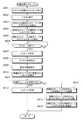
図28は論理デバイス管理情報603を示す。論理デバイス管理情報603は、各論理デバイス202につきエントリ901から918までの情報を保持する。 FIG. 28 shows logical
エントリ901には論理デバイス202を識別するためのLDEV番号が格納される。 The
エントリ902には、LDEV番号により特定される論理デバイス202の容量(サイズ)が格納される。 The
エントリ903には、LDEV番号により特定される論理デバイス202のLDEVタイプが格納される。ストレージシステム130には、ディスクキャッシュ上でのデータ管理単位やデバイス管理情報の格納形態(ディスク空間への管理情報格納有無や格納形態など)の異なる、複数のデバイスタイプの論理デバイス202を定義することができる。LDEVタイプは、各論理デバイス202がどのデバイスタイプであるかを示す。 The
エントリ904には、LDEV番号により特定される論理デバイス202のLDEV状態が格納される。LDEV状態は、論理デバイス202のデバイス状態を示す。LDEV状態には、「オンライン」、「オフライン」、「未実装」、「ブロックド」がある。「オンライン」は、論理デバイス202が正常に稼動し、1つ以上のポート131にLUパスが定義され、ホスト計算機100からアクセスできる状態であることを示す。「オフライン」は、論理デバイス202は定義され、正常に稼動しているが、LUパスが未定義であるなどの理由でホスト計算機100からはアクセスできない状態にあることを示す。「未実装」は、論理デバイス202に物理デバイス又は外部デバイスが割り当てられていない等の理由でホスト計算機100からアクセスできない状態にあることを示す。「ブロックド」は、論理デバイス202に障害が発生してホスト計算機100からアクセスできない状態を示す。エントリ603dの初期値は、「未実装」であるが、論理デバイス定義処理により、「オフライン」に更新され、更にLUパス定義処理により、「オンライン」に更新される。 The
エントリ905には、LDEV番号により特定される論理デバイス202のLUSE状態が格納される。LUSE状態は、論理ユニット201がLUSE構成を有しているか否かを示すとともに、論理ユニット201がLUSE構成を有している場合における、論理ユニット201に割り当てられている複数の論理デバイス202のうち代表的な論理デバイスのLDEV番号を示す。 The
エントリ906には、連結LDEV数が格納される。連結LDEV数は、論理ユニット201がLUSE構成を有している場合における、論理ユニット201に割り当てられている論理デバイス202の個数を示す。 The
エントリ907には、連結LDEV番号リストが格納される。連結LDEV番号リストは、論理ユニット201がLUSE構成を有している場合における、論理ユニット201に割り当てられている論理デバイス202のLDEV番号のリストを示す。 The
エントリ908には、LUパス数が格納される。LUパスとは、ホスト計算機100が論理ユニット201に接続するためのパスである。LUパス数は、LUパスの本数を示す。 The
エントリ909には、それぞれのホストグループの番号、ホストグループに属するホスト計算機100からアクセス可能なポート131を識別するためのポート番号、ポート131に割り当てられる論理ユニット201を識別するための情報(ターゲットID又はLUN)がリスト形式で格納される。 The
エントリ910には、それぞれのホストグループに属するホスト計算機100の台数が格納される。 The
エントリ911には、複数のホスト計算機100による一つの論理ユニット201へのアクセスが許可されている場合における、ホスト計算機100のホスト名がリスト形式で格納される。 The
エントリ912には、論理デバイス202がVDEV連結構成を有している場合における、論理デバイス202に割り当てられている仮想デバイス203の個数が格納される。 The
エントリ913には、論理デバイス202と仮想デバイス203とが一対一に対応してない場合における、仮想デバイス203の番号(VDEV番号)がリスト形式で格納される。 In the
エントリ914には、論理デバイス202と仮想デバイス203との間のマッピング関係を示す情報が格納される。例えば、エントリ914には、論理デバイス202がCVS構成を有している場合における、仮想デバイス203上の論理デバイス202のオフセット位置や、論理デバイス202がVDEV連結構成を有している場合における、論理デバイス202上の仮想デバイス203のオフセット位置などが格納される。 The
エントリ915には、論理デバイス202が同期コピー中又は移行中の場合における、コピー先又は移行先の論理デバイス202の番号が格納される。論理デバイス202が同期コピー中でもなく移行中でもない場合には、エントリ915には無効値が格納される。 The
エントリ916には、論理デバイス202がデータ移行中である場合における、データ移行が完了した最終アドレスを示す情報(以下、データ移行進捗ポインタと呼ぶ)が格納される。データ移行進捗ポインタは、ホスト計算機100から論理デバイス202へのI/O要求をストレージシステム130が受領した際に、アクセス先の記憶領域が移行済みであるのか或いは移行未完了であるのかを判定し、処理を選択する際に用いられる。 The
エントリ917には、論理デバイス202が同期コピー中か、データ移行中か、また両状態のどちらにも該当しないか、を示す情報(以下、同期コピー/データ移行中フラグと称する。)が格納される。 The
エントリ918には、暗号化フラグが格納される。暗号化フラグとは、物理デバイス205又は拡張デバイス206に書き込まれるデータを暗号化する否かを示すフラグ情報である。暗号化フラグがオンに設定されると、ストレージシステム130は、物理デバイス205又は拡張デバイス206に書き込まれるデータを暗号化する。 The
図29は仮想デバイス管理情報604を示す。仮想デバイス管理情報604は、各仮想デバイス203につきエントリ1001から1010までの情報を保持する。 FIG. 29 shows the virtual
エントリ1001には、仮想デバイス203を識別するためのVDEV番号が格納される。 The
エントリ1002には、VDEV番号により特定される仮想デバイス203の容量(サイズ)が格納される。 The
エントリ1003には、VDEV番号により特定される仮想デバイス203のVDEV状態が格納される。VDEV状態は、仮想デバイス203のデバイス状態を示す。VDEV状態には、「オンライン」、「オフライン」、「未実装」、「ブロックド」がある。「オンライン」は、仮想デバイス203が正常に稼動し、かつホスト計算機100から仮想デバイス203へのパスが定義され、ホスト計算機100からアクセスできる状態であることを示す。「オフライン」は、仮想デバイス203は定義され、正常に稼動しているが、仮想デバイス203へのパスが未定義であるなどの理由で、ホスト計算機100からはアクセスできない状態にあることを示す。「未実装」は、仮想デバイス203に物理デバイス又は外部デバイスが割り当てられていない等の理由でホスト計算機100からアクセスできない状態にあることを示す。「ブロックド」は、仮想デバイス203に障害が発生してホスト計算機100からアクセスできない状態を示す。エントリ1003の初期値は、「未実装」であるが、仮想デバイス定義処理により、「オフライン」に更新され、更にパス定義処理により「オンライン」に更新される。 The
エントリ1004には、VDEV番号により特定される仮想デバイス203のRAID構成が格納される。RAID構成には、例えば、RAIDレベル、データパリティ数、ドライブ構成、ストライプサイズなどがある。 The
エントリ1005には、論理デバイス202がCVS構成を有している場合における、一つの仮想デバイス203から割り当てられる論理デバイス202の個数が格納される。 The
エントリ1006には、VDEV番号により特定される仮想デバイス203が割り当てられている論理デバイス202の番号がリスト形式で格納される。 The
エントリ1007には、論理デバイス202と仮想デバイス203との間のマッピング関係を示す情報がリスト形式で格納される。例えば、エントリ1007には、論理デバイス202がCVS構成を有している場合における、仮想デバイス203上の論理デバイス202のオフセット位置や、論理デバイス202がVDEV連結構成を有している場合における、論理デバイス202上の仮想デバイス203のオフセット位置等が格納される。 The
エントリ1008には、仮想デバイス203に割り当てられるデバイスグループ204の個数が格納される。例えば、エントリ1008には、仮想デバイス203がVDEV離散の構成を有している場合における、仮想デバイス203に割り当てられるデバイスグループ204の個数が格納される。また例えば、エントリ1008は、論理ユニット移動処理中において、複数のデバイスグループ204を一つの仮想デバイス203に割り当てるために用いられる。 The
エントリ1009には、仮想デバイス203に割り当てられるデバイスグループ204の番号がリスト形式で格納される。 The
エントリ1010には、仮想デバイス203とデバイスグループ204との間のマッピング関係を示す情報がリスト形式で格納される。 The
図30はデバイスグループ管理情報605を示す。デバイスグループ管理情報605は各デバイスグループ204につきエントリ1101から1110までの情報を保持する。 FIG. 30 shows device
エントリ1101には、デバイスグループ204を識別するためのデバイスグループ番号が格納される。 The
エントリ1102には、デバイスグループ番号により特定されるデバイスグループ204の容量(サイズ)が格納される。 The
エントリ1103には、デバイスグループ番号により特定されるデバイスグループ204のDEVGr状態が格納される。DEVGr状態は、デバイスグループ204のデバイス状態を示す。DEVGr状態には、「オンライン」、「オフライン」、「未実装」、「ブロックド」がある。「オンライン」は、デバイスグループ204が正常に稼動し、かつホスト計算機100からデバイスグループ204へのパスが定義され、ホスト計算機100からアクセスできる状態であることを示す。「オフライン」は、デバイスグループ204は定義され正常に稼動しているが、デバイスグループ204へのパスが未定義であるなどの理由でホスト計算機100からはアクセスできない状態にあることを示す。「未実装」は、デバイスグループ204に物理デバイス又は外部デバイスが割り当てられていない等の理由でホスト計算機100からアクセスできない状態にあることを示す。「ブロックド」は、デバイスグループ204に障害が発生してホスト計算機100からアクセスできない状態を示す。エントリ1103の初期値は、「未実装」であるが、デバイスグループ定義処理により、「オフライン」に更新され、更にパス定義処理により「オンライン」に更新される。 The
エントリ1104には、デバイスグループ番号により特定されるデバイスグループ204のRAID構成が格納される。RAID構成には、例えば、RAIDレベル、データパリティ数、ドライブ構成、ストライプサイズなどがある。但し、論理ユニット移動処理中の場合のように、一つの拡張デバイス206を一つのデバイスグループ204に割り当てる場合には、デバイスグループ204には、RAID構成は適用されない。 The
エントリ1105には、デバイスグループ204に割り当てられている仮想デバイス203の個数が格納される。LUSE構成を有する論理ユニット201を移動させるときには、一つのデバイスグループ204に複数の仮想デバイス203を割り当てることがあるので、このような場合には、エントリ1105の値が更新される。 The
エントリ1106には、デバイスグループ番号により特定されるデバイスグループ204に割り当てられている仮想デバイス203の番号がリスト形式で格納される。 The
エントリ1107には、デバイスグループ204と仮想デバイス203との間のマッピング関係を示す情報がリスト形式で格納される。 The
エントリ1108には、デバイスグループ204に割り当てられるデバイス(物理デバイス205又は拡張デバイス206)の個数が格納される。 The
エントリ1109には、デバイスグループ204に割り当てられるデバイス(物理デバイス205又は拡張デバイス206)の番号がリスト形式で格納される。 The
エントリ1110には、デバイスグループ204とデバイス(物理デバイス205又は拡張デバイス206)との間のマッピング関係を示す情報がリスト形式で格納される。例えば、エントリ1110には、図13乃至図15に示すように、拡張デバイス206の一部分のみがデバイスグループ204に割り当てられているような場合における、拡張デバイス206の先頭からのアドレスと容量などが格納される。 The
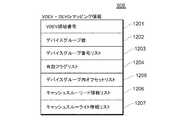
図31はVDEV−DEVGrマッピング情報606を示す。VDEV−DEVGrマッピング情報606は、エントリ1201からエントリ1207までの情報を保持する。 FIG. 31 shows VDEV-
エントリ1201には、VDEV領域を識別するための番号が格納される。VDEV領域とは、仮想デバイス203の一部の領域をいう。 The
エントリ1202には、VDEV領域に対応付けられているデバイスグループ204の個数が格納される。 The
エントリ1203には、VDEV領域に対応付けられているデバイスグループ204の番号がリスト形式で格納される。 The
エントリ1204には、有効フラグがリスト形式で格納される。有効フラグとは、論理ユニット201に割り当てられる仮想デバイス203にミラーリング又はパリティ生成等の処理を実行するか否かを示すフラグ情報である。論理ユニット移行処理中では、有効フラグはオフに設定され、移行元の論理ユニット201に割り当てられる仮想デバイス203に対するミラーリング又はパリティ生成等の処理は実施されない。 The
エントリ1205には、デバイスグループ204に対応付けられているVDEV領域のオフセットアドレスがリスト形式で格納される。 The
エントリ1206には、それぞれのVDEV領域について、キャッシュスルーリードの動作モードで動作するか否かを示す情報がリスト形式で格納される。 In the
エントリ1207には、それぞれのVDEV領域について、キャッシュスルーライトの動作モードで動作するか否かを示す情報がリスト形式で格納される。 The
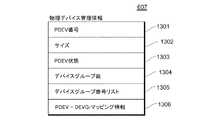
図32は物理デバイス管理情報607を示す。物理デバイス管理情報607は、ストレージシステム130内に定義される各物理デバイス205につきエントリ1301からエントリ1306までの情報を保持する。 FIG. 32 shows physical
エントリ1301には、物理デバイス205を識別するための物理デバイス番号が格納される。 The
エントリ1302には、物理デバイス番号により特定される物理デバイス205の容量(サイズ)が格納される。 The
エントリ1303には、物理デバイス番号により特定される物理デバイス205のデバイス状態が格納される。デバイス状態としては、「オンライン」、「オフライン」、「未実装」、「ブロックド」がある。「オンライン」は、物理デバイス205が正常に稼動し、且つその物理デバイス205が論理デバイス202に割り当てられている状態を示す。「オフライン」は、物理デバイス205は定義され、正常に稼動しているが、その物理デバイス205は論理デバイス202に割り当てられていないことを示す。「未実装」は、物理デバイス205がディスク装置137上に定義されていない状態にあることを示す。「ブロックド」は、物理デバイス205に障害が発生してアクセスできない状態であることを示す。エントリ1303の初期値は「未実装」に設定されており、物理デバイス定義処理により「オフライン」に更新され、物理デバイス205が論理デバイス202に定義された契機で「オンライン」に更新される。 The
エントリ1304には、一つの物理デバイス205の記憶領域が部分的に複数のデバイスグループ204に割り当てられているような場合(図15参照)に一つの物理デバイス205に割り当てられているデバイスグループ204の個数が格納される。 In the
エントリ1305には、物理デバイス205に割り当てられるデバイスグループ204の番号がリスト形式で格納される。 The
エントリ1306には、物理デバイス205とデバイスグループ204との間のマッピング関係を示す情報が格納される。 The
図33は拡張デバイス管理情報608を示す。拡張デバイス管理情報608は、外部ストレージシステム150が有する外部ボリューム301をストレージシステム130内の拡張デバイス206(内部ボリューム)として仮想化するためのものである。拡張デバイス管理情報608は、各外部ボリューム301につきエントリ1401からエントリ1411までの情報を保持する。 FIG. 33 shows extended
エントリ1401には、拡張デバイス206を識別するためのEDEV番号が格納される。EDEV番号は、ストレージシステム130内で外部ボリューム301を一意に識別するための識別番号である。 The
エントリ1402には、EDEV番号により特定される拡張デバイス206の容量(サイズ)が格納される。 The
エントリ1403には、EDEV番号により特定される拡張デバイス206のデバイス状態が格納される。デバイス状態としては、「オンライン」、「オフライン」、「未実装」、「ブロックド」がある。「オンライン」は、拡張デバイス206が正常に稼動し、且つその拡張デバイス206が論理デバイス202に割り当てられている状態を示す。「オフライン」は、拡張デバイス206は定義され、正常に稼動しているが、その拡張デバイス206は論理デバイス202に割り当てられていないことを示す。「未実装」は、拡張デバイス206が定義されていない状態にあることを示す。「ブロックド」は、拡張デバイス206に障害が発生してアクセスできない状態であることを示す。エントリ1403の初期値は「未実装」に設定されており、拡張デバイス定義処理により「オフライン」に更新され、拡張デバイス206が論理デバイス202に定義された契機で「オンライン」に更新される。 The
エントリ1404には、一つの拡張デバイス206の記憶領域が部分的に複数のデバイスグループ204に割り当てられているような場合(図15参照)に一つの拡張デバイス206に割り当てられているデバイスグループ204の個数が格納される。 In the
エントリ1405には、拡張デバイス206に割り当てられるデバイスグループ204の番号がリスト形式で格納される。 The
エントリ1406には、拡張デバイス206とデバイスグループ204との間のマッピング関係を示す情報が格納される。 The
エントリ1407には、拡張デバイス206を仮想化する外部ストレージシステム150を識別するためのストレージ識別情報が格納される。ストレージ識別情報としては、例えば、外部ストレージシステム150を製造販売するベンダを識別するためのベンダ識別情報と各ベンダが一意に割り振るシリアル番号との組み合わせ等が考えられる。 The
エントリ1408には、外部ストレージシステム150が管理する外部ボリューム301のLDEV番号が格納される。 The
エントリ1409には、ストレージシステム130内の複数のポート131のうち外部ストレージシステム150に接続するためのイニシエータポートを識別するためのポート番号が格納される。 The
エントリ1410には、外部ボリューム301が外部ストレージシステム150内の一つ以上のポート151に定義されている場合における、それらのポート151を識別するためのポートID、及び外部ボリューム301を識別するためのターゲットID及びLUNがリスト形式で格納される。 In the
エントリ1411には、アクセス制御情報が格納される。アクセス制御情報は、外部ボリューム301が複数のストレージシステム130によって共有されている場合において、外部ボリューム301の各領域についてどのストレージシステム130がアクセス権限を有しているかを管理するための情報である。 The
図34は計算機システム500のソフトウェア構成を示す。ストレージシステム130内の制御メモリ135には、各種の構成管理情報(ホストグループ管理情報601、LUパス管理情報602、論理デバイス管理情報603、仮想デバイス管理情報604、デバイスグループ管理情報605、VDEV−DEVGrマッピング情報606、物理デバイス管理情報607、拡張デバイス管理情報608、及びデバイス機能管理情報609)が格納されている。 FIG. 34 shows a software configuration of the
デバイス機能管理情報609は、各論理デバイス202に設定される各種の属性を示す情報を保持する。論理デバイス202の属性情報の例としては、論理デバイス202へのアクセスを特定のホスト計算機100にのみに制限するアクセス制限情報、論理デバイス202へのリードアクセス又はライトアクセスを抑止するアクセス属性情報、論理デバイス202に格納されるデータへの暗号化適用の有無やデータの暗号化及び復号化に用いられる鍵情報などの暗号化情報を挙げることができる。 The device
ストレージシステム130内のメモリ133には、上述した各種の構成管理情報が格納される他、ストレージI/O処理プログラム221、及び論理ユニット移動処理プログラム222が格納されている。ストレージI/O処理プログラム221が実行するストレージI/O処理の詳細、及び論理ユニット移動処理プログラム222が実行する論理ユニット移動処理プログラム222の詳細については、後述する。 The
管理サーバ110内のメモリ112には、上述した各種の構成管理情報が格納される他、論理ユニット移動指示処理プログラム241、及びストレージ負荷監視プログラム242が格納されている。論理ユニット移動指示処理プログラム241が実行するLU移動指示処理の詳細、及びストレージ負荷監視プログラム242が実行する処理の詳細については、後述する。 The
ホスト計算機100内のメモリ102には、デバイスパス管理情報251、及びホストI/O処理プログラム261が格納されている。ホスト計算機100は、ストレージシステム130又は外部ストレージシステム150が提供する論理デバイスを認識し、論理デバイスをデバイスファイルに対応付けて管理する。デバイスパス管理情報251には、論理デバイスとデバイスファイルとの対応関係を示す情報が含まれている。例えば、ストレージシステム130が有する複数のポート131に同一の論理デバイスが割り当てられている場合には、同一の論理デバイスから複数のデバイスファイルが生成される。ホスト計算機100は、同一の論理デバイスに対応付けられている複数のデバイスファイルを一元管理し、論理デバイスへの入出力負荷を分散したり、或いはネットワーク障害時におけるパス切り替えを制御したりする。 The
尚、管理サーバ110又は管理端末140からストレージ管理ソフトウェア又はストレージ管理者からの指示を受けて、ストレージシステム130の構成を変更した場合や、或いはストレージシステム130内の各部位が障害又は自動交替等によって構成が変更した場合に、ストレージシステム130内のある一つの制御プロセッサ132は、制御メモリ135内の構成管理情報を更新する。更に、制御プロセッサ132は、ストレージシステム130の構成変更により構成管理情報が更新された旨を他の制御プロセッサ132、管理端末140、及び管理サーバ110に通知し、他の制御メモリ135に格納されている全ての構成管理情報を最新の情報に更新させる。 In addition, in response to an instruction from the storage management software or the storage administrator from the
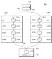
次に、図35を参照しながらCVS構成を有する論理ユニットの移動処理の概要について説明する。 Next, an overview of the migration process of a logical unit having a CVS configuration will be described with reference to FIG.
ストレージシステム130aは、論理ユニット201a−1,201a−2,論理デバイス202a−1,202a−2,仮想デバイス203a,及び拡張デバイス206aを備える。論理ユニット201a−1は、パス401−1を介してホスト計算機100に接続されている。論理ユニット201a−2は、パス401−2を介してホスト計算機100に接続されている。仮想デバイス203aは、複数の記憶領域203a−1,203a−2に分割されている。一方の記憶領域203a−1は、論理デバイス202a−1を介して論理ユニット202a−1にマッピングされており、他方の記憶領域203a−1は、論理デバイス202a−1を介して論理ユニット202a−1にマッピングされている。それぞれの論理ユニット201a−1,201a−2は、仮想デバイス203aの一部を仮想化したものであり、CVS構成を有している。 The
拡張デバイス206aは、外部ボリューム301を仮想化したものであり、複数の記憶領域206a−1,206a−2に分割されている。一方の記憶領域206a−1は、記憶領域203a−1にマッピングされており、他方の記憶領域206a−2は、記憶領域203a−2にマッピングされている。 The
ストレージシステム130a(移動元ストレージ)内の論理ユニット201a−2(移動元論理ユニット)にあるデータをストレージシステム130b(移動先ストレージ)内の論理ユニット201b(移動先論理ユニット)に移動する処理について概説する。論理ユニット移動処理は、下記の(1)〜(9)の処理手順を含む。 Outline of processing for moving data in
(1)ストレージシステム130bは、外部ボリューム301と、ストレージシステム130bとの間を外部接続するためのパス405を定義し、外部ボリューム301を仮想化する拡張デバイス206bをストレージシステム130b内に作成する。拡張デバイス206bは、複数の記憶領域206b−1,206b−2に分割されている。拡張デバイス206bの記憶容量は、外部ボリューム301の記憶量に等しい。記憶領域206b−2の記憶容量は、論理ユニット201a−2の記憶容量に等しい。(1) The
(2)ストレージシステム130bは、外部ボリューム301の記憶容量と同一の記憶容量を有する仮想デバイス203bをストレージシステム130b内に作成する。仮想デバイス203bは、複数の記憶領域203b−1,203b−2に分割されている。記憶領域203b−2の記憶容量は、論理ユニット201a−2の記憶容量に等しい。(2) The
(3)ストレージシステム130bは、論理ユニット201a−2とストレージシステム130bとの間を外部接続するためのパス404を定義し、論理ユニット201a−2を仮想化するための拡張デバイス206cをストレージシステム130b内に作成する。(3) The
(4)ストレージシステム130bは、拡張デバイス206cを仮想デバイス203b(より詳細には、記憶領域203b−2)にマッピングする。(4) The
(5)ストレージシステム130bは、論理デバイス202a−2の論理構成と同一の論理構成を有する論理デバイス202bをストレージシステム130b内に作成する。仮想デバイス203b(より詳細には、記憶領域203b−2)は、論理デバイス202bにマッピングされる。(5) The
(6)ストレージシステム130bは、論理ユニット201a−2の論理構成と同一の論理構成を有する論理ユニット201bをストレージシステム130b内に作成し、ホスト計算機100と論理ユニット201bとを接続するためのパス403を定義する。仮想デバイス202bは、論理ユニット201bにマッピングされる。(6) The
(7)ホスト計算機100は、外部ボリューム301にアクセスするための経路として、パス401−2からパス403に切り替える。このとき、パス401−2を削除する等して、ホスト計算機100から論理ユニット201a−2へのアクセスを禁止する。尚、パス401−2からパス403へのパス切り替えは、ストレージシステム130a,130b,又は管理サーバ110等が行っても良い。また、必ずしもパス401−2を削除する必要はなく、例えば、パス401−2をパス403の交替パス(例えば、システム障害時に使用するためのパス)として設定し、パス401−2の状態を無効としたまま、パス401−2を残しても良い。(7) The
上記の処理により、論理ユニット201bは、論理ユニット201a−2を仮想化したものであるだけでなく、外部ボリューム301の一部をも仮想化したものでもあるので、論理ユニット移動処理中における、ホスト計算機100から論理ユニット201a−2へのデータ入出力経路は、パス403→ストレージシステム130b内の記憶階層(LU/LDEV/VDEV/EDEV)→パス404→ストレージシステム130a内の記憶階層(LU/LDEV/VDEV/EDEV)→パス402→外部ボリューム301となる。 With the above processing, the
(8)ストレージシステム130aは、ストレージシステム130aのディスクキャッシュに蓄積されている全てのダーティデータを外部ボリューム301にデステージするためにストレージシステム130aの動作モードをキャッシュスルーモードに設定する。尚、ストレージシステム130aは、自発的に動作モードをキャッシュスルーモードに設定してもよく、或いは外部(例えば、ストレージシステム130b、ホスト計算機100、又は管理サーバ110など)からの指示に基づいて、動作モードをキャッシュスルーモードに設定してもよい。(8) The
(9)ストレージシステム130aのディスクキャッシュに蓄積されているダーティデータの全てを外部ボリューム301にデステージできたならば、ストレージシステム130bは、拡張デバイス206cと仮想デバイス203bとの間のマッピング関係を解除し、拡張デバイス206bを仮想デバイス203bにマッピングする。更に、ストレージシステム130bは、パス404を削除する。(9) If all of the dirty data stored in the disk cache of the
尚、CVS構成を有する論理ユニットの移動処理では、複数のストレージシステム130a,130bによって外部ボリューム301の一部が共有されるので、外部ボリューム301に対する排他制御が必要になる。外部ボリューム301に対する排他制御は、外部ストレージシステム150が実行してもよく、或いは複数のストレージシステム130a,130bが連携しながら実行してもよい。 Note that in the migration process of a logical unit having a CVS configuration, a part of the
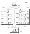
次に、図36を参照しながらLUSE構成を有する論理ユニットの移動処理の概要について説明する。 Next, the outline of the migration processing of the logical unit having the LUSE configuration will be described with reference to FIG.
ストレージシステム130aは、論理ユニット201a,論理デバイス202a−1,202a−2,仮想デバイス203a−1,203a−2,及び拡張デバイス206a−1,206a−2を備える。論理ユニット201aは、パス401を介してホスト計算機100に接続されている。論理ユニット201aは、複数の論理デバイス202a−1,202a−2を一つに集めた記憶領域であり、LUSE構成を有している。拡張デバイス206a−1は、外部ボリューム301−1を仮想化したものであり、仮想デバイス203a−1にマッピングされている。仮想デバイス203a−1は、論理デバイス202a−1にマッピングされている。拡張デバイス206a−2は、外部ボリューム301−2を仮想化したものであり、仮想デバイス203a−2にマッピングされている。仮想デバイス203a−2は、論理デバイス202a−2にマッピングされている。 The
ストレージシステム130a(移動元ストレージ)内の論理ユニット201a(移動元論理ユニット)にあるデータをストレージシステム130b(移動先ストレージ)内の論理ユニット201b(移動先論理ユニット)に移動する処理について概説する。論理ユニット移動処理は、下記の(1)〜(9)の処理手順を含む。 An outline of processing for moving data in the
(1)ストレージシステム130bは、外部ボリューム301−1,301−2と、ストレージシステム130bとの間を外部接続するためのパス405−1,405−2を定義し、外部ボリューム301−1,301−2を仮想化する拡張デバイス206b−1,206b−2をストレージシステム130b内に作成する。(1) The
(2)ストレージシステム130bは、外部ボリューム301−1の記憶容量と同一の記憶容量を有する仮想デバイス203b−1と、外部ボリューム301−2の記憶容量と同一の記憶容量を有する仮想デバイス203b−2をストレージシステム130b内に作成する。(2) The
(3)ストレージシステム130bは、論理ユニット201aとストレージシステム130bとの間を外部接続するためのパス404を定義し、論理ユニット201aを仮想化するための拡張デバイス206cをストレージシステム130b内に作成する。拡張デバイス206cは、複数の記憶領域206c−1,206c−2に分割される。(3) The
(4)ストレージシステム130bは、拡張デバイス206cを仮想デバイス203b−1,203b−2にマッピングする(より詳細には、記憶領域206c−1を仮想デバイス203b−1にマッピングし、記憶領域206c−2を仮想デバイス203b−2にマッピングする。)。(4) The
(5)ストレージシステム130bは、論理デバイス202a−1の論理構成と同一の論理構成を有する論理デバイス202b−1と、論理デバイス202a−2の論理構成と同一の論理構成を有する論理デバイス202b−2とをそれぞれストレージシステム130b内に作成する。仮想デバイス203b−1は、論理デバイス202b−1にマッピングされ、仮想デバイス203b−2は、論理デバイス202b−2にマッピングされる。(5) The
(6)ストレージシステム130bは、論理ユニット201aの論理構成と同一の論理構成を有する論理ユニット201bをストレージシステム130b内に作成し、ホスト計算機100と論理ユニット201bとを接続するためのパス403を定義する。論理デバイス202b−1,202b−2は、論理ユニット201bにマッピングされる。(6) The
(7)ホスト計算機100は、外部ボリューム301−1,301−2にアクセスするための経路として、パス401からパス403に切り替える。このとき、パス401を削除する等して、ホスト計算機100から論理ユニット201aへのアクセスを禁止する。尚、パス401からパス403へのパス切り替えは、ストレージシステム130a,130b,又は管理サーバ110等が行っても良い。また、必ずしもパス401を削除する必要はなく、例えば、パス401をパス403の交替パス(例えば、システム障害時に使用するためのパス)として設定し、パス401の状態を無効としたまま、パス401を残しても良い。(7) The
上記の処理により、論理ユニット201bは、論理ユニット201aを仮想化したものであるだけでなく、外部ボリューム301−1,301−2をも仮想化したものでもあるので、論理ユニット移動処理中における、ホスト計算機100から論理ユニット201aへのデータ入出力経路は、パス403→ストレージシステム130b内の記憶階層(LU/LDEV/VDEV/EDEV)→パス404→ストレージシステム130a内の記憶階層(LU/LDEV/VDEV/EDEV)→パス402−1,402−2→外部ボリューム301−1,301−2となる。 Through the above processing, the
(8)ストレージシステム130aは、ストレージシステム130aのディスクキャッシュに蓄積されている全てのダーティデータを外部ボリューム301−1,301−2にデステージするためにストレージシステム130aの動作モードをキャッシュスルーモードに設定する。尚、ストレージシステム130aは、自発的に動作モードをキャッシュスルーモードに設定してもよく、或いは外部(例えば、ストレージシステム130b、ホスト計算機100、又は管理サーバ110など)からの指示に基づいて、動作モードをキャッシュスルーモードに設定してもよい。(8) The
(9)ストレージシステム130aのディスクキャッシュに蓄積されているダーティデータの全てを外部ボリューム301−1,301−2にデステージできたならば、ストレージシステム130bは、拡張デバイス206cと仮想デバイス203b−1,203b−2との間のマッピング関係を解除し、拡張デバイス206b−1を仮想デバイス203b−1にマッピングし、拡張デバイス206b−2を仮想デバイス203b−2にマッピングする。更に、ストレージシステム130bは、パス404を削除する。(9) If all of the dirty data stored in the disk cache of the
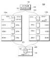
次に、図37を参照しながら外部ボリュームRAID構成を有する論理ユニットの移動処理の概要について説明する。 Next, an overview of migration processing of a logical unit having an external volume RAID configuration will be described with reference to FIG.
ストレージシステム130aは、論理ユニット201a,論理デバイス202a,仮想デバイス203a,及び拡張デバイス206a−1,206a−2を備える。論理ユニット201aは、パス401を介してホスト計算機100に接続されている。論理ユニット201aは、複数の外部ボリューム301−1,301−2にRAID構成を適用することにより、これらの外部ボリューム301−1,301−2を一つの記憶領域に仮想化したものである。複数の外部ボリューム301−1,301−2に適用されるRAID構成として、本実施例では、RAID1(ミラーリング)を例示する。RAID1構成においては、外部ボリューム301−1は、プライマリボリュームであるのに対し、外部ボリューム301−2は、セカンダリボリューム(ミラーボリューム)である。外部ボリューム301−1,301−2に適用されるRAID構成としては、RAID1に限らず、RAID0,RAID5,RAID6等でもよい。拡張デバイス206a−1は、外部ボリューム301−1を仮想化したものである。拡張デバイス206a−2は、外部ボリューム301−2を仮想化したものである。仮想デバイス203aは、複数の拡張デバイス206a−1,206a−2にRAID構成を適用することにより、一つの記憶領域に仮想化したものである。仮想デバイス203aの中でプライマリボリュームに対応する記憶領域は、論理デバイス202aにマッピングされている。論理デバイス202aは、論理ユニット201aにマッピングされている。 The
ストレージシステム130a(移動元ストレージ)内の論理ユニット201a(移動元論理ユニット)にあるデータをストレージシステム130b(移動先ストレージ)内の論理ユニット201b(移動先論理ユニット)に移動する処理について概説する。論理ユニット移動処理は、下記の(1)〜(9)の処理手順を含む。 An outline of processing for moving data in the
(1)ストレージシステム130bは、外部ボリューム301−1,301−2と、ストレージシステム130bとの間を外部接続するためのパス405−1,405−2を定義し、外部ボリューム301−1,301−2を仮想化する拡張デバイス206b−1,206b−2をストレージシステム130b内に作成する。(1) The
(2)ストレージシステム130bは、複数の外部ボリューム301−1,301−2を仮想化するための仮想デバイス203bをストレージシステム130b内に作成する。複数の外部ボリューム301−1,301−2を仮想化するためのRAID構成として、ミラーリングを適用する場合には、仮想デバイス203bの記憶容量は、複数の外部ボリューム301−1,301−2のそれぞれの記憶容量の総和に等しい。(2) The
(3)ストレージシステム130bは、論理ユニット201aとストレージシステム130bとの間を外部接続するためのパス404を定義し、論理ユニット201aを仮想化するための拡張デバイス206cをストレージシステム130b内に作成する。(3) The
(4)ストレージシステム130bは、拡張デバイス206cを仮想デバイス203b(より詳細には、仮想デバイス203bの中でプライマリボリュームに対応する記憶領域)にマッピングする。(4) The
(5)ストレージシステム130bは、論理デバイス202aの論理構成と同一の論理構成を有する論理デバイス202bをストレージシステム130b内に作成する。仮想デバイス203bの中でプライマリボリュームに対応する記憶領域は、論理デバイス202bにマッピングされる。(5) The
(6)ストレージシステム130bは、論理ユニット201aの論理構成と同一の論理構成を有する論理ユニット201bをストレージシステム130b内に作成し、ホスト計算機100と論理ユニット201bとを接続するためのパス403を定義する。論理デバイス202bは、論理ユニット201bにマッピングされる。(6) The
(7)ホスト計算機100は、外部ボリューム301−1,301−2にアクセスするための経路として、パス401からパス403に切り替える。このとき、パス401を削除する等して、ホスト計算機100から論理ユニット201aへのアクセスを禁止する。尚、パス401からパス403へのパス切り替えは、ストレージシステム130a,130b,又は管理サーバ110等が行っても良い。また、必ずしもパス401を削除する必要はなく、例えば、パス401をパス403の交替パス(例えば、システム障害時に使用するためのパス)として設定し、パス401の状態を無効としたまま、パス401を残しても良い。(7) The
上記の処理により、論理ユニット201bは、論理ユニット201aを仮想化したものであるだけでなく、外部ボリューム301−1,301−2をも仮想化したものでもあるので、論理ユニット移動処理中における、ホスト計算機100から論理ユニット201aへのデータ入出力経路は、パス403→ストレージシステム130b内の記憶階層(LU/LDEV/VDEV/EDEV)→パス404→ストレージシステム130a内の記憶階層(LU/LDEV/VDEV/EDEV)→パス402−1,402−2→外部ボリューム301−1,301−2となる。 Through the above processing, the
(8)ストレージシステム130aは、ストレージシステム130aのディスクキャッシュに蓄積されている全てのダーティデータを外部ボリューム301−1,301−2にデステージするためにストレージシステム130aの動作モードをキャッシュスルーモードに設定する。尚、ストレージシステム130aは、自発的に動作モードをキャッシュスルーモードに設定してもよく、或いは外部(例えば、ストレージシステム130b、ホスト計算機100、又は管理サーバ110など)からの指示に基づいて、動作モードをキャッシュスルーモードに設定してもよい。(8) The
(9)ストレージシステム130aのディスクキャッシュに蓄積されているダーティデータの全てを外部ボリューム301−1,301−2にデステージできたならば、ストレージシステム130bは、拡張デバイス206cと仮想デバイス203bとの間のマッピング関係を解除し、拡張デバイス206b−1,206b−2を仮想デバイス203bにマッピングする。更に、ストレージシステム130bは、パス404を削除する。(9) If all of the dirty data stored in the disk cache of the
次に、図38を参照しながら、VMA付きボリュームの移動処理の概要について説明する。 Next, the outline of the VMA volume migration process will be described with reference to FIG.
ストレージシステム130aは、論理ユニット201a,論理デバイス202a,仮想デバイス203a,及び拡張デバイス206aを備える。論理ユニット201aは、パス401を介してホスト計算機100に接続されている。論理デバイス202aは、VMA付きボリュームであり、ホスト計算機100からアクセス可能なユーザ領域202a−1と、管理情報を格納するための管理領域202a−2とを含む。管理情報には、例えば、VMA付きボリュームのアクセス属性が含まれる。ユーザ領域202a−1は、論理ユニット201aに割り当てられることにより、ホスト計算機100により認識可能である。管理領域202a−2は、論理ユニット201aに割り当てられておらず、ホスト計算機100から認識することはできない。仮想デバイス203aは、ホスト計算機100からアクセス可能なユーザ領域203a−1と、管理情報を格納するための管理領域203a−2とを含む。拡張デバイス206aは、ホスト計算機100からアクセス可能なユーザ領域206a−1と、管理情報を格納するための管理領域206a−2とを含む。拡張デバイス206a内のユーザ領域206a−1は、外部ボリューム301内のユーザ領域301−1を仮想化したものである。拡張デバイス206a内の管理領域206a−2は、外部ボリューム301内の管理領域301−2を仮想化したものである。ユーザ領域206a−1は、ユーザ領域203a−1にマッピングされている。管理領域206a−2は、管理領域203a−2にマッピングされている。ユーザ領域203a−1は、ユーザ領域202a−1にマッピングされている。管理領域203a−2は、管理領域202a−2にマッピングされている。 The
尚、移動元のストレージシステム130aは、外部ボリューム301に管理情報を格納するのではなく、ストレージシステム130a内のディスクキャッシュ又はその他のメモリに管理情報を格納している場合には、論理ユニット201aの移動処理を実行する前準備として、外部ボリューム301に管理情報をデステージしておく必要がある。 The
ストレージシステム130a(移動元ストレージ)内の論理ユニット201a(移動元論理ユニット)にあるデータをストレージシステム130b(移動先ストレージ)内の論理ユニット201b(移動先論理ユニット)に移動する処理について概説する。論理ユニット移動処理は、下記の(1)〜(9)の処理手順を含む。 An outline of processing for moving data in the
(1)ストレージシステム130bは、外部ボリューム301と、ストレージシステム130bとの間を外部接続するためのパス405を定義し、外部ボリューム301を仮想化する拡張デバイス206bをストレージシステム130b内に作成する。拡張デバイス206bは、ホスト計算機100からアクセス可能なユーザ領域206b−1と、管理情報を格納するための管理領域206b−2とを含む。ストレージシステム130bは、管理領域301−2を管理領域206b−2にマッピングする。(1) The
(2)ストレージシステム130bは、外部ボリューム301を仮想化するための仮想デバイス203bをストレージシステム130b内に作成する。仮想デバイス203bは、ホスト計算機100からアクセス可能なユーザ領域203b−1と、管理情報を格納するための管理領域203b−2とを含む。ストレージシステム130bは、管理領域206b−2を管理領域203b−2にマッピングする。(2) The
(3)ストレージシステム130bは、論理ユニット201aとストレージシステム130bとの間を外部接続するためのパス404を定義し、論理ユニット201aを仮想化するための拡張デバイス206cをストレージシステム130b内に作成する。(3) The
(4)ストレージシステム130bは、拡張デバイス206cを仮想デバイス203b内のユーザ領域203b−1にマッピングする。(4) The
(5)ストレージシステム130bは、論理デバイス202aの論理構成と同一の論理構成を有する論理デバイス202bをストレージシステム130b内に作成する。論理デバイス202bは、ホスト計算機100からアクセス可能なユーザ領域202b−1と、管理情報を格納するための管理領域202b−2とを含む。ユーザ領域203b−1は、ユーザ領域202b−1にマッピングされる。管理領域203b−2は、管理領域202b−2にマッピングされる。(5) The
(6)ストレージシステム130bは、論理ユニット201aの論理構成と同一の論理構成を有する論理ユニット201bをストレージシステム130b内に作成し、ホスト計算機100と論理ユニット201bとを接続するためのパス403を定義する。ユーザ領域202b−1は、論理ユニット201bにマッピングされる。(6) The
(7)ホスト計算機100は、外部ボリューム301にアクセスするための経路として、パス401からパス403に切り替える。このとき、パス401を削除する等して、ホスト計算機100から論理ユニット201aへのアクセスを禁止する。尚、パス401からパス403へのパス切り替えは、ストレージシステム130a,130b,又は管理サーバ110等が行っても良い。また、必ずしもパス401を削除する必要はなく、例えば、パス401をパス403の交替パス(例えば、システム障害時に使用するためのパス)として設定し、パス401の状態を無効としたまま、パス401を残しても良い。(7) The
上記の処理により、論理ユニット201bは、論理ユニット201aを仮想化したものであるだけでなく、外部ボリューム301内のユーザ領域301−1をも仮想化したものでもあるので、論理ユニット移動処理中における、ホスト計算機100から論理ユニット201aへのデータ入出力経路は、パス403→ストレージシステム130b内の記憶階層(LU/LDEV/VDEV/EDEV)→パス404→ストレージシステム130a内の記憶階層(LU/LDEV/VDEV/EDEV)→パス402→外部ボリューム301となる。 Through the above processing, the
尚、ストレージシステム130bは、外部ボリューム130内の管理領域301−2を仮想デバイス203bによって仮想化しているため、パス405を介して管理情報を参照することができる。論理ユニット201aの移動処理中において、ストレージシステム130aがパス402を介して外部ボリューム130内の管理情報を参照するためには、仮想デバイス203b内の管理領域203b−2から外部ボリューム301内の管理領域301−2への書き込みをキャッシュスルーモードに設定しておき、管理領域301−2内の管理情報を常時最新にしておく必要がある。外部ボリューム301内の管理領域301−2に書き込まれている管理情報の更新は、移動先のストレージシステム130bによって行われる。 The
(8)ストレージシステム130aは、ストレージシステム130aのディスクキャッシュに蓄積されている全てのダーティデータを外部ボリューム301にデステージするためにストレージシステム130aの動作モードをキャッシュスルーモードに設定する。尚、ストレージシステム130aは、自発的に動作モードをキャッシュスルーモードに設定してもよく、或いは外部(例えば、ストレージシステム130b、ホスト計算機100、又は管理サーバ110など)からの指示に基づいて、動作モードをキャッシュスルーモードに設定してもよい。(8) The
(9)ストレージシステム130aのディスクキャッシュに蓄積されているダーティデータの全てを外部ボリューム301にデステージできたならば、ストレージシステム130bは、拡張デバイス206cと仮想デバイス203bとの間のマッピング関係を解除し、拡張デバイス206b内のユーザ領域206b−1を仮想デバイス203b内のユーザ領域203b−1にマッピングする。更に、ストレージシステム130bは、パス404を削除する。(9) If all of the dirty data stored in the disk cache of the
尚、図38に示す方法は、外部ボリューム301がVMA付きボリュームの場合だけでなく、メインフレームボリュームの場合にも、上述の処理手順(1)〜(9)と同様の手順を経て論理ユニット201aを移動させることができる。 Note that the method shown in FIG. 38 is not limited to the case where the
次に、図39を参照しながら、VMA付きボリュームの移動処理の他の方法について説明する。 Next, another method for moving a volume with a VMA will be described with reference to FIG.
ストレージシステム130aは、論理ユニット201a−1,202a−1,論理デバイス202a,仮想デバイス203a,及び拡張デバイス206aを備える。論理ユニット201a−1は、パス401を介してホスト計算機100に接続されており、ホスト計算機100から認識可能である。一方、論理ユニット201a−2は、ホスト計算機100に接続されておらず、ホスト計算機100からの認識は不可能である。論理ユニット201a−2は、論理ユニット201a−1をストレージシステム130aからストレージシステム130bに移動させる間のときにのみ一時的に作成される。論理デバイス202aは、VMA付きボリュームであり、ホスト計算機100からアクセス可能なユーザ領域202a−1と、管理情報を格納するための管理領域202a−2とを含む。管理情報には、例えば、VMA付きボリュームのアクセス属性が含まれる。ユーザ領域202a−1は、論理ユニット201a−1に割り当てられることにより、ホスト計算機100により認識可能である。管理領域202a−2は論理ユニット201a−2に割り当てられているが、ホスト計算機100から認識することはできない。仮想デバイス203aは、ホスト計算機100からアクセス可能なユーザ領域203a−1と、管理情報を格納するための管理領域203a−2とを含む。拡張デバイス206aは、ホスト計算機100からアクセス可能なユーザ領域206a−1と、管理情報を格納するための管理領域206a−2とを含む。拡張デバイス206a内のユーザ領域206a−1は、外部ボリューム301内のユーザ領域301−1を仮想化したものである。拡張デバイス206a内の管理領域206a−2は、外部ボリューム301内の管理領域301−2を仮想化したものである。ユーザ領域206a−1は、ユーザ領域203a−1にマッピングされている。管理領域206a−2は、管理領域203a−2にマッピングされている。ユーザ領域203a−1は、ユーザ領域202a−1にマッピングされている。管理領域203a−2は、管理領域202a−2にマッピングされている。 The
ストレージシステム130a(移動元ストレージ)内の論理ユニット201a(移動元論理ユニット)にあるデータをストレージシステム130b(移動先ストレージ)内の論理ユニット201b(移動先論理ユニット)に移動する処理について概説する。論理ユニット移動処理は、下記の(1)〜(9)の処理手順を含む。 An outline of processing for moving data in the
(1)ストレージシステム130bは、外部ボリューム301と、ストレージシステム130bとの間を外部接続するためのパス405を定義し、外部ボリューム301を仮想化する拡張デバイス206bをストレージシステム130b内に作成する。拡張デバイス206bは、ホスト計算機100からアクセス可能なユーザ領域206b−1と、管理情報を格納するための管理領域206b−2とを含む。(1) The
(2)ストレージシステム130bは、外部ボリューム301を仮想化するための仮想デバイス203bをストレージシステム130b内に作成する。仮想デバイス203bは、ホスト計算機100からアクセス可能なユーザ領域203b−1と、管理情報を格納するための管理領域203b−2とを含む。(2) The
(3)ストレージシステム130bは、論理ユニット201a−1とストレージシステム130bとの間を外部接続するためのパス404−1,論理ユニット201a−2とストレージシステム130bとの間を外部接続するためのパス404−2とをそれぞれ定義し、論理ユニット201a−1を仮想化するための拡張デバイス206c−1,論理ユニット201a−2を仮想化するための拡張デバイス206c−2をそれぞれストレージシステム130b内に作成する。(3) The
(4)ストレージシステム130bは、拡張デバイス206c−1を仮想デバイス203b内のユーザ領域203b−1にマッピングし、拡張デバイス206c−2を仮想デバイス203b内の管理領域203b−2にマッピングする。(4) The
(5)ストレージシステム130bは、論理デバイス202aの論理構成と同一の論理構成を有する論理デバイス202bをストレージシステム130b内に作成する。論理デバイス202bは、ホスト計算機100からアクセス可能なユーザ領域202b−1と、管理情報を格納するための管理領域202b−2とを含む。ユーザ領域203b−1は、ユーザ領域202b−1にマッピングされる。管理領域203b−2は、管理領域202b−2にマッピングされる。(5) The
(6)ストレージシステム130bは、論理ユニット201a−1の論理構成と同一の論理構成を有する論理ユニット201bをストレージシステム130b内に作成し、ホスト計算機100と論理ユニット201bとを接続するためのパス403を定義する。ユーザ領域202b−1は、論理ユニット201bにマッピングされる。(6) The
(7)ホスト計算機100は、外部ボリューム301にアクセスするための経路として、パス401からパス403に切り替える。このとき、パス401を削除する等して、ホスト計算機100から論理ユニット201a−1へのアクセスを禁止する。尚、パス401からパス403へのパス切り替えは、ストレージシステム130a,130b,又は管理サーバ110等が行っても良い。また、必ずしもパス401を削除する必要はなく、例えば、パス401をパス403の交替パス(例えば、システム障害時に使用するためのパス)として設定し、パス401の状態を無効としたまま、パス401を残しても良い。(7) The
上記の処理により、論理ユニット201bは、論理ユニット201a−1を仮想化したものであるだけでなく、外部ボリューム301内のユーザ領域301−1をも仮想化したものでもあるので、論理ユニット移動処理中における、ホスト計算機100から論理ユニット201aへのデータ入出力経路は、パス403→ストレージシステム130b内の記憶階層(LU/LDEV/VDEV/EDEV)→パス404−1→ストレージシステム130a内の記憶階層(LU/LDEV/VDEV/EDEV)→パス402→外部ボリューム301となる。 Through the above processing, the
尚、ストレージシステム130aは、外部ボリューム130内の管理領域301−1を仮想デバイス203a−1によって仮想化しているため、パス402を介して管理情報を参照することができる。論理ユニット201aの移動処理中において、ストレージシステム130bが外部ボリューム130内の管理情報を参照するためには、パス404−2及び論理ユニット201a−2を介して外部ボリューム130内の管理領域301−2にアクセスすればよい。外部ボリューム301内の管理領域301−2に書き込まれている管理情報の更新は、移動元のストレージシステム130aによって行われる。 The
(8)ストレージシステム130aは、ストレージシステム130aのディスクキャッシュに蓄積されている全てのダーティデータを外部ボリューム301にデステージするためにストレージシステム130aの動作モードをキャッシュスルーモードに設定する。尚、ストレージシステム130aは、自発的に動作モードをキャッシュスルーモードに設定してもよく、或いは外部(例えば、ストレージシステム130b、ホスト計算機100、又は管理サーバ110など)からの指示に基づいて、動作モードをキャッシュスルーモードに設定してもよい。(8) The
(9)ストレージシステム130aのディスクキャッシュに蓄積されているダーティデータの全てを外部ボリューム301にデステージできたならば、ストレージシステム130bは、拡張デバイス206c−1とユーザ領域203b−1との間のマッピング関係を解除するとともに、拡張デバイス206c−2と管理領域203b−2との間のマッピング関係を解除する。更に、ストレージシステム130bは、拡張デバイス206b内のユーザ領域206b−1をユーザ領域203b−1にマッピングするとともに、管理領域206b−2を管理領域203b−2にマッピングする。更に、ストレージシステム130bは、パス404を削除する。(9) If all of the dirty data stored in the disk cache of the
尚、図39に示す方法は、外部ボリューム301がVMA付きボリュームの場合だけでなく、メインフレームボリュームの場合にも、上述の処理手順(1)〜(9)と同様の手順を経て論理ユニット201a−1を移動させることができる。 Note that the method shown in FIG. 39 is not limited to the case where the
図38に示す方法と図39に示す方法との間の主な相違点は次の通りである。図39に示す方法では、移動先のストレージシステム130bは、移動元のストレージシステム130aを介して管理領域301−2にアクセスするが、図38に示す方法では、移動先のストレージシステム130bは、管理領域301−2に直接アクセスする。図39に示す方法では、管理領域301−2内の管理情報の更新は、移動元のストレージシステム130aが実行するが、図38に示す方法では、管理領域301−2内の管理情報の更新は、移動先のストレージシステム130bが実行する。 The main differences between the method shown in FIG. 38 and the method shown in FIG. 39 are as follows. In the method shown in FIG. 39, the migration
次に、図40を参照しながら、VMA付きボリュームの移動処理の他の方法について説明する。 Next, another method for moving a volume with a VMA will be described with reference to FIG.
ストレージシステム130aは、論理ユニット201a,201a',論理デバイス202a,仮想デバイス203a,及び拡張デバイス206aを備える。論理ユニット201aは、パス401を介してホスト計算機100に接続されており、ホスト計算機100から認識可能である。一方、論理ユニット201a'は、ホスト計算機100に接続されておらず、ホスト計算機100からの認識は不可能である。論理ユニット201a'は、論理ユニット201aをストレージシステム130aからストレージシステム130bに移動させる間のときにのみ一時的に作成される。論理ユニット201a'は、ユーザ領域201a−1'と、管理領域201a−2'とを含む。論理デバイス202aは、VMA付きボリュームであり、ホスト計算機100からアクセス可能なユーザ領域202a−1と、管理情報を格納するための管理領域202a−2とを含む。管理情報には、例えば、VMA付きボリュームのアクセス属性が含まれる。ユーザ領域202a−1は、論理ユニット201aに割り当てられることにより、ホスト計算機100により認識可能である。ユーザ領域202a−1は、論理ユニット201a'内のユーザ領域201a−1'にも割り当てられる。管理領域202a−2は、論理ユニット201a'内の管理領域201a−2'に割り当てられる。仮想デバイス203aは、ホスト計算機100からアクセス可能なユーザ領域203a−1と、管理情報を格納するための管理領域203a−2とを含む。拡張デバイス206aは、ホスト計算機100からアクセス可能なユーザ領域206a−1と、管理情報を格納するための管理領域206a−2とを含む。拡張デバイス206a内のユーザ領域206a−1は、外部ボリューム301内のユーザ領域301−1を仮想化したものである。拡張デバイス206a内の管理領域206a−2は、外部ボリューム301内の管理領域301−2を仮想化したものである。ユーザ領域206a−1は、ユーザ領域203a−1にマッピングされている。管理領域206a−2は、管理領域203a−2にマッピングされている。ユーザ領域203a−1は、ユーザ領域202a−1にマッピングされている。管理領域203a−2は、管理領域202a−2にマッピングされている。 The
ストレージシステム130a(移動元ストレージ)内の論理ユニット201a(移動元論理ユニット)にあるデータをストレージシステム130b(移動先ストレージ)内の論理ユニット201b(移動先論理ユニット)に移動する処理について概説する。論理ユニット移動処理は、下記の(1)〜(9)の処理手順を含む。 An outline of processing for moving data in the
(1)ストレージシステム130bは、外部ボリューム301と、ストレージシステム130bとの間を外部接続するためのパス405を定義し、外部ボリューム301を仮想化する拡張デバイス206bをストレージシステム130b内に作成する。拡張デバイス206bは、ホスト計算機100からアクセス可能なユーザ領域206b−1と、管理情報を格納するための管理領域206b−2とを含む。(1) The
(2)ストレージシステム130bは、外部ボリューム301を仮想化するための仮想デバイス203bをストレージシステム130b内に作成する。仮想デバイス203bは、ホスト計算機100からアクセス可能なユーザ領域203b−1と、管理情報を格納するための管理領域203b−2とを含む。(2) The
(3)ストレージシステム130bは、論理ユニット201a'とストレージシステム130bとの間を外部接続するためのパス404を定義し、論理ユニット201a'を仮想化するための拡張デバイス206cをストレージシステム130b内に作成する。拡張デバイス206cは、ホスト計算機100からアクセス可能なユーザ領域206c−1と、管理情報を格納するための管理領域206c−2とを含む。(3) The
(4)ストレージシステム130bは、拡張デバイス206c内のユーザ領域206c−1を仮想デバイス203b内のユーザ領域203b−1にマッピングし、拡張デバイス206c内の管理領域206c−2を仮想デバイス203b内の管理領域203b−2にマッピングする。(4) The
(5)ストレージシステム130bは、論理デバイス202aの論理構成と同一の論理構成を有する論理デバイス202bをストレージシステム130b内に作成する。論理デバイス202bは、ホスト計算機100からアクセス可能なユーザ領域202b−1と、管理情報を格納するための管理領域202b−2とを含む。ユーザ領域203b−1は、ユーザ領域202b−1にマッピングされる。管理領域203b−2は、管理領域202b−2にマッピングされる。(5) The
(6)ストレージシステム130bは、論理ユニット201aの論理構成と同一の論理構成を有する論理ユニット201bをストレージシステム130b内に作成し、ホスト計算機100と論理ユニット201bとを接続するためのパス403を定義する。ユーザ領域202b−1は、論理ユニット201bにマッピングされる。(6) The
(7)ホスト計算機100は、外部ボリューム301にアクセスするための経路として、パス401からパス403に切り替える。このとき、パス401を削除する等して、ホスト計算機100から論理ユニット201a−1へのアクセスを禁止する。尚、パス401からパス403へのパス切り替えは、ストレージシステム130a,130b,又は管理サーバ110等が行っても良い。また、必ずしもパス401を削除する必要はなく、例えば、パス401をパス403の交替パス(例えば、システム障害時に使用するためのパス)として設定し、パス401の状態を無効としたまま、パス401を残しても良い。(7) The
上記の処理により、論理ユニット201bは、論理ユニット201aを仮想化したものであるだけでなく、外部ボリューム301内のユーザ領域301−1をも仮想化したものでもあるので、論理ユニット移動処理中における、ホスト計算機100から論理ユニット201aへのデータ入出力経路は、パス403→ストレージシステム130b内の記憶階層(LU/LDEV/VDEV/EDEV)→パス404→ストレージシステム130a内の記憶階層(LU/LDEV/VDEV/EDEV)→パス402→外部ボリューム301となる。 Through the above processing, the
尚、ストレージシステム130aは、外部ボリューム130内の管理領域301−1を仮想デバイス203a−1によって仮想化しているため、パス402を介して管理情報を参照することができる。論理ユニット201aの移動処理中において、ストレージシステム130bが外部ボリューム130内の管理情報を参照するためには、パス404及び論理ユニット201a'を介して外部ボリューム130内の管理領域301−2にアクセスすればよい。外部ボリューム301内の管理領域301−2に書き込まれている管理情報の更新は、移動元のストレージシステム130aによって行われる。 The
(8)ストレージシステム130aは、ストレージシステム130aのディスクキャッシュに蓄積されている全てのダーティデータを外部ボリューム301にデステージするためにストレージシステム130aの動作モードをキャッシュスルーモードに設定する。尚、ストレージシステム130aは、自発的に動作モードをキャッシュスルーモードに設定してもよく、或いは外部(例えば、ストレージシステム130b、ホスト計算機100、又は管理サーバ110など)からの指示に基づいて、動作モードをキャッシュスルーモードに設定してもよい。(8) The
(9)ストレージシステム130aのディスクキャッシュに蓄積されているダーティデータの全てを外部ボリューム301にデステージできたならば、ストレージシステム130bは、拡張デバイス206cと仮想デバイス203bとの間のマッピング関係を解除するとともに、拡張デバイス206bを仮想デバイス203bにマッピングする。より詳細には、ストレージシステム130bは、拡張デバイス206b内のユーザ領域206b−1を仮想デバイス203b内のユーザ領域203b−1にマッピングするとともに、拡張デバイス206b内の管理領域206b−2を仮想デバイス203b内の管理領域203b−2にマッピングする。更に、ストレージシステム130bは、パス404を削除する。(9) If all of the dirty data stored in the disk cache of the
次に、図41を参照しながら、複数の論理ユニットを移動させる処理の概要について説明する。 Next, an overview of processing for moving a plurality of logical units will be described with reference to FIG.
ストレージシステム130aは、複数の論理ユニット201a−1,201a−2,複数の論理デバイス202a−1,202a−2,複数の仮想デバイス203a−1,203a−2,及び複数の拡張デバイス206a−1,206a−2を備えている。拡張デバイス206a−1は、外部ボリューム301−1を仮想化したものであり、パス402−1を介して外部ストレージシステム150に接続している。拡張デバイス206a−1は、仮想デバイス203a−1にマッピングされている。仮想デバイス203a−1は、論理デバイス202a−1にマッピングされている。論理デバイス202a−1は論理ユニット201a−1にマッピングされている。論理ユニット201a−1は、外部ボリューム301−1を仮想化したものであり、パス401−1を介してホスト計算機100に接続されている。 The
一方、拡張デバイス206a−2は、外部ボリューム301−2を仮想化したものであり、パス402−2を介して外部ストレージシステム150に接続している。拡張デバイス206a−2は、仮想デバイス203a−2にマッピングされている。仮想デバイス203a−2は、論理デバイス202a−2にマッピングされている。論理デバイス202a−2は、論理ユニット201a−2にマッピングされている。論理ユニット201a−2は、外部ボリューム301−2を仮想化したものであり、パス401−2を介してホスト計算機100に接続されている。 On the other hand, the
さて、上記の構成において、複数の論理ユニット201a−1,201a−2をストレージシステム130aからストレージシステム130bへ移動するには、上述の処理手順と同様に、ストレージシステム130bは、移動先となる複数の論理ユニット201b−1,201b−2を作成する。論理ユニット201b−1は、パス403−1を介してホスト計算機100に接続する。論理ユニット201b−2は、パス403−2を介してホスト計算機100に接続する。更に、ストレージシステム130bは、移動元の複数の論理ユニット201a−1,201a−2を仮想化するため複数の拡張デバイス206c−1,206c−2,複数の仮想デバイス203b−1,203b−2,複数の論理デバイス202b−1,202b−2をそれぞれ作成する。拡張デバイス206c−1は、論理ユニット201a−1の移動処理中においては、論理ユニット201a−1を仮想化する一方で、論理ユニット201a−1の移動処理後(より詳細には、仮想デバイス203a−1に書き込まれたダーティデータのデステージ完了後)においては、パス405−1を介して外部ボリューム301−1に接続し、外部ボリューム301−1を仮想化する。拡張デバイス206c−2は、論理ユニット201a−2の移動処理中においては、論理ユニット201a−2を仮想化する一方で、論理ユニット201a−2の移動処理後(より詳細には、仮想デバイス203a−2に書き込まれたダーティデータのデステージ完了後)においては、パス405−2を介して外部ボリューム301−2に接続し、外部ボリューム301−2を仮想化する。 In the above configuration, in order to move a plurality of
尚、複数の論理ユニットを移動させるための指示は、管理サーバ110(図2参照)から各ストレージシステム130a,130bに与えてもよく、或いはホスト計算機100から各ストレージシステム130a,130bに与えても良い。 An instruction to move a plurality of logical units may be given from the management server 110 (see FIG. 2) to each
次に、図42乃至図46を参照しながら論理ユニット移動処理の詳細について説明を加える。 Next, the details of the logical unit migration process will be described with reference to FIGS.
図42は論理ユニット移動指示処理ルーチンを示す。論理ユニット移動指示処理ルーチンは、管理サーバ110内の論理ユニット移動指示処理プログラム241によって実行される。 FIG. 42 shows a logical unit movement instruction processing routine. The logical unit movement instruction processing routine is executed by the logical unit movement instruction processing program 241 in the
管理サーバ110がストレージシステム130a(移動元ストレージ)、及びストレージシステム130b(移動先ストレージ)に対して、一つ以上の論理ユニットを移動させる指示を与える(ステップ4201)。このとき、管理サーバ110を操作するストレージ管理者によって、各ストレージシステム130a,130bに論理ユニット移動指示が与えられてもよく、或いは管理サーバ110内の管理ソフトウェアが各ストレージシステム130a,130bに論理ユニット移動指示を与えても良い。尚、論理ユニットの移動指示は、ホスト計算機100から各ストレージシステム130a,130bに与えても良い。 The
各ストレージシステム130a,130bは、論理ユニット移動指示を受けると、指定された論理ユニットを移動させるための処理を実行する(ステップ4202)。 When each
指定された全ての論理ユニットのうち一部の論理ユニットの移動が未だ完了してない場合には(ステップ4203;NO)、各ストレージシステム130a,130bは、論理ユニット移動処理を実行する(ステップ4202)。 If migration of some of the specified logical units has not yet been completed (
指定された全ての論理ユニットの移動が完了すると(ステップ4203;YES)、各ストレージシステム130a,130bは、管理サーバ110に移動完了報告をする(ステップ4204)。尚、論理ユニット移動指示がホスト計算機100から各ストレージシステム130a,130bに与えられる場合には、各ストレージシステム130a,130bは、ホスト計算機100に移動完了報告をする。 When the migration of all the specified logical units is completed (
図43は論理ユニット移動処理サブルーチンを示す。論理ユニット移動処理サブルーチンは、ストレージシステム130内の論理ユニット移動処理プログラム222によって実行される。 FIG. 43 shows a logical unit movement processing subroutine. The logical unit migration processing subroutine is executed by the logical unit
論理ユニット移動処理のサブルーチンが起動すると、各ストレージシステム130a,130bは、移動体対象選出処理(ステップ4301)、移動準備処理(ステップ4302)、及び移動処理(ステップ4303)を実行する。 When the logical unit migration process subroutine is started, the
図44は移動対象選出処理サブルーチンを示す。移動対象選出処理サブルーチンが起動すると、ストレージシステム130aは、移動対象となる論理ユニットに対応する論理デバイス(移動対象となる論理デバイス)を選出する(ステップ4401)。例えば、LUSE構成では、一つの論理ユニットにつき複数の論理デバイスが選出される。 FIG. 44 shows a movement target selection processing subroutine. When the migration target selection processing subroutine is activated, the
次に、ストレージシステム130aは、移動対象となる論理デバイスを使用する全てのホスト計算機100を選出する(ステップ4402)。例えば、同一のホストグループに属するホスト計算機100のみならず、他のホストグループに属するホスト計算機100も選出する。 Next, the
次に、ストレージシステム130aは、移動対象となる論理デバイスに対応するVDEV領域(移動対象となるVDEV領域)を選出する(ステップ4403)。VDEV領域は、一つの仮想デバイスの一部に対応する場合もあれば、複数の仮想デバイスに対応する場合もある。例えば、CVS構成では、移動対象となる論理デバイスに対応するVDEV領域として、仮想デバイスの一部が選出される。一方、VDEV連結構成では、移動対象となる論理デバイスに対応するVDEV領域として、複数の仮想デバイスが選出される。 Next, the
次に、ストレージシステム130aは、移動対象となるVDEV領域に対応するデバイスグループ(移動対象となるデバイスグループ)を選出する(ステップ4404)。デバイスグループは、一つのVDEV領域の一部に対応する場合もあれば、複数のVDEV領域に対応する場合もある。例えば、VDEV離散構成では、移動対象となるVDEV領域に対応するデバイスグループとして、複数のデバイスグループが選出される。 Next, the
次に、ストレージシステム130aは、移動対象となるデバイスグループに対応する拡張デバイス(移動対象となる拡張デバイス)を選出する(ステップ4405)。拡張デバイスは、一つのデバイスグループの一部に対応する場合もあれば、複数のデバイスグループに対応する場合もある。例えば、一つの拡張デバイスの一部の記憶領域はあるデバイスグループに割り当てられており、他の記憶領域は他のデバイスグループに割り当てられているような場合には、移動対象となるデバイスグループに対応する拡張デバイスとして、拡張デバイスの一部が選出される。一方、外部ボリュームRAID構成では、移動対象となるデバイスグループに対応する拡張デバイスとして、複数の拡張デバイスが選出される。 Next, the
次に、ストレージシステム130aは、移動対象となる拡張デバイスに対応する外部ボリュームを選出する(ステップ4406)。 Next, the
上記の処理により、移動対象となる論理ユニットに対応する論理デバイス、その論理デバイスに対応する仮想デバイス、その仮想デバイスに対応するデバイスグループ、そのデバイスグループに対応する拡張デバイス、その拡張デバイスに対応する外部ボリュームをそれぞれ選出することができる。 With the above processing, the logical device corresponding to the logical unit to be moved, the virtual device corresponding to the logical device, the device group corresponding to the virtual device, the expansion device corresponding to the device group, and the expansion device Each external volume can be selected.
図45は移動準備処理サブルーチンを示す。移動準備処理サブルーチンが起動すると、ストレージシステム130aは、ストレージシステム130bから外部ボリュームへのアクセス許可を設定する(ステップ4501)。 FIG. 45 shows a movement preparation processing subroutine. When the migration preparation processing subroutine is started, the
ストレージシステム130bは、ストレージシステム130bから外部ボリュームに接続するためのパスを定義し、外部ボリュームを仮想化するための第一の拡張デバイス(図1の拡張デバイス206bに相当)をストレージシステム130b内に作成する(ステップ4502)。 The
ストレージシステム130bは、ストレージシステム130b内の第一の拡張デバイスをストレージシステム130b内のデバイスグループに対応付ける(ステップ4503)。例えば、外部ボリュームRAID構成では、複数の第一の拡張デバイスが一つのデバイスグループに対応付けられる。 The
ストレージシステム130bは、ストレージシステム130b内の第一の拡張デバイスに対応付けられているデバイスグループをストレージシステム130b内の仮想デバイスに対応付ける(ステップ4504)。 The
ストレージシステム130aは、ストレージシステム130bからストレージシステム130a内の移動元論理ユニットへのアクセス許可を設定する(ステップ4505)。 The
ストレージシステム130bは、ストレージシステム130b内の第二の拡張デバイス(図1の拡張デバイス206cに相当)をストレージシステム130a内の移動対象となる論理ユニットに対応付ける(ステップ4506)。 The
例えば、移動対象となる論理ユニットが外部ボリュームRAID構成を有している場合には、ストレージシステム130b内の第二の拡張デバイスは、ストレージシステム130a内の仮想デバイスの一部(パリティデータ及びミラーデータを格納している記憶領域を除く。)に対応付けられる。 For example, when the logical unit to be migrated has an external volume RAID configuration, the second expansion device in the
また例えば、移動対象となる論理ユニットがCVS構成を有している場合には、ストレージシステム130b内の第二の拡張デバイスは、ストレージシステム130a内の仮想デバイスの一部に対応付けられる。 For example, when the logical unit to be moved has a CVS configuration, the second expansion device in the
また例えば、移動対象となる論理ユニットがLUSE構成を有している場合には、ストレージシステム130b内の第二の拡張デバイスは、ストレージシステム130a内の複数の仮想デバイスに対応付けられる。 Further, for example, when the logical unit to be moved has a LUSE configuration, the second expansion device in the
また例えば、移動対象となる論理ユニットがVMA付きボリュームである場合には、ストレージシステム130b内の第二の拡張デバイスは、ストレージシステム130a内の仮想デバイスの一部(ユーザ領域)に対応付けられる。 For example, when the logical unit to be migrated is a volume with VMA, the second expansion device in the
ストレージシステム130bは、ストレージシステム130b内の第二の拡張デバイスをストレージシステム130b内のデバイスグループに対応付ける(ステップ4507)。 The
ストレージシステム130bは、ストレージシステム130b内の第二の拡張デバイスに対応付けられているデバイスグループをストレージシステム130b内の仮想デバイスに対応付ける(ステップ4508)。 The
例えば、移動対象となる論理ユニットが外部ボリュームRAID構成を有している場合には、ストレージシステム130b内の第二の拡張デバイスは、ストレージシステム130b内の仮想デバイスの一部(パリティデータ及びミラーデータを格納している記憶領域を除く。)に対応付けられる。 For example, when the logical unit to be migrated has an external volume RAID configuration, the second expansion device in the
また例えば、移動対象となる論理ユニットがCVS構成を有している場合には、ストレージシステム130b内の第二の拡張デバイスは、ストレージシステム130b内の仮想デバイスの一部に対応付けられる。 For example, when the logical unit to be moved has a CVS configuration, the second expansion device in the
また例えば、移動対象となる論理ユニットがLUSE構成を有している場合には、ストレージシステム130b内の第二の拡張デバイスは、ストレージシステム130b内の複数の仮想デバイスに対応付けられる。 Further, for example, when the logical unit to be moved has a LUSE configuration, the second expansion device in the
また例えば、移動対象となる論理ユニットがVMA付きボリュームである場合には、ストレージシステム130b内の第二の拡張デバイスは、ストレージシステム130b内の仮想デバイスの一部(ユーザ領域)に対応付けられる。 For example, when the logical unit to be migrated is a volume with VMA, the second expansion device in the
ストレージシステム130bは、第一の拡張デバイスに対応付けられているストレージシステム130b内のデバイスグループとストレージシステム130b内の仮想デバイスとの間のマッピング関係を無効とし、第二の拡張デバイスに対応付けられているストレージシステム130b内のデバイスグループとストレージシステム130b内の仮想デバイスとの間のマッピング関係を有効とする(ステップ4509)。 The
ストレージシステム130bは、ストレージシステム130bの動作モードをキャッシュスルーモードに設定し、ストレージシステム130aの動作モードをライトアフタモードに設定する(ステップ4510)。 The
ストレージシステム130bは、ストレージシステム130b内に移動先の論理ユニットを作成する(ステップ4511)。 The
ストレージシステム130bは、移動先の論理ユニットにアクセス属性を設定する(ステップ4512)。アクセス属性として、例えば、ホストグループに関する設定や交替パスに関する設定などがある。 The
ストレージシステム130bは、ストレージシステム130bから外部ボリュームに書き込まれるデータを暗号化する機能を解除する(ステップ4513)。論理ユニットの移動処理中において、外部ボリュームへ書き込まれるデータは、移動元のストレージシステム130aによって暗号化される。 The
ストレージシステム130bは、移動先の論理ユニットとホスト計算機100とを接続するためのパスを定義する(ステップ4514)。移動先の論理ユニットが複数存在する場合には、それぞれの移動先の論理ユニットとホスト計算機100とを接続するためのパスを定義する。 The
ストレージシステム130bは、移動先の論理ユニットをホスト計算機100に認識させる(ステップ4515)。移動対象となる論理ユニットを使用するホスト計算機100が複数存在する場合には、それぞれのホスト計算機100に移動先の論理ユニットを認識させる。 The
ストレージシステム130bは、移動先の論理ユニットとホスト計算機100とを接続するパスを、移動元の論理ユニットとホスト計算機100とを接続するパスの交替パスとして設定する(ステップ4516)。 The
図46は移動処理サブルーチンを示す。移動処理サブルーチンが起動すると、ホスト計算機100は、移動元の論理ユニットへのI/O要求を停止する(ステップ4601)。ストレージシステム130aがホスト計算機100からのI/O要求を禁止してもよい。移動元の論理ユニットを使用するホスト計算機100が複数存在する場合には、それぞれのホスト計算機100から移動元の論理ユニットへのI/O要求を停止又は禁止する。 FIG. 46 shows the movement processing subroutine. When the migration processing subroutine is started, the
ホスト計算機100は、移動元の論理ユニットに接続するパスから移動先の論理ユニットに接続するパスに切り替えるとともに、移動元の論理ユニットに接続するパスを削除する(ステップ4602)。移動元の論理ユニットを使用するホスト計算機100が複数存在する場合には、それぞれのホスト計算機100は、パス切り替えを同時に実行する。 The
移動元のストレージシステム130aは、ホスト計算機100からのアクセスを禁止する(ステップ4603)。 The migration
移動先のストレージシステム130bは、ストレージシステム130bの動作モードとして、キャッシュスルーモードを解除し、ライトアフタモードに設定する(ステップ4604)。 As the operation mode of the
移動元のストレージシステム130aは、ストレージシステム130aの動作モードとして、ライトアフタモードを解除し、キャッシュスルーモードに設定する(ステップ4605)。 The migration
移動元のストレージシステム130aのディスクキャッシュに蓄積されているダーティデータの全てを外部ボリュームにデステージできたならば(ステップ4606;YES)、移動先のストレージシステム130bは、第二の拡張デバイスに対応付けられているストレージシステム130b内のデバイスグループとストレージシステム130b内の仮想デバイスとの間のマッピング関係を無効とし、第一の拡張デバイスに対応付けられているストレージシステム130b内のデバイスグループとストレージシステム130b内の仮想デバイスとの間のマッピング関係を有効とする(ステップ4607)。 If all of the dirty data stored in the disk cache of the migration
ストレージシステム130bは、ストレージシステム130bから外部ボリュームへのアクセスを許可する一方で、ストレージシステム130aから外部ボリュームへのアクセスを禁止する設定(アクセス排他設定)を行う(ステップ4608)。 The
ストレージシステム130bは、外部ボリュームに書き込まれるデータを暗号化する機能をアクティブに設定する(ステップ4609)。 The
ストレージシステム130bは、ストレージシステム130b内の第二の拡張デバイスとストレージシステム130a内の移動元の論理ユニットとを接続するパスを削除する(ステップ4610)。 The
移動元のストレージシステム130aと、移動先のストレージシステム130bとによって、外部ボリュームを共有する場合(例えば、移動元の論理ユニットがCVS構成を有している場合)には(ステップ4611;YES)、移動元のストレージシステム130aは、移動処理後の論理ユニットとストレージシステム130a内の仮想デバイスとの間のマッピング関係を無効にする(ステップ4612)。 When the external volume is shared by the migration
移動元のストレージシステム130aと、移動先のストレージシステム130bとによって、外部ボリュームを共有しない場合には(ステップ4611;NO)、ストレージシステム130aは、ストレージシステム130aと外部ボリュームとを接続するパスを削除する(ステップ4613)。 If the external volume is not shared by the migration
移動元のストレージシステム130aは、外部ボリュームを仮想化するためにストレージシステム130a内に作成された拡張デバイス、その拡張デバイスに対応付けられているデバイスグループ、そのデバイスグループに対応付けられている仮想デバイス、その仮想デバイスに対応付けられている論理デバイス、その論理デバイスに対応付けられている論理ユニット、その論理ユニットとホスト計算機100とを接続するためのパスを何れも全て削除する(ステップ4614)。 The migration
外部ストレージシステム150は、ストレージシステム130aから外部ボリュームへのアクセスを禁止する(ステップ4615)。 The
図47はストレージI/O処理ルーチンを示す。ストレージI/O処理ルーチンは、ストレージI/O処理プログラム221によって実行される。 FIG. 47 shows a storage I / O processing routine. The storage I / O processing routine is executed by the storage I /
ホスト計算機100からのI/O要求を受領したストレージシステム130は、論理デバイス管理情報603を参照し、ホスト計算機100のアクセス権を確認する(ステップ4701)。 The
ホスト計算機100がアクセス権を有しない場合には(ステップ4701;NO)、ストレージシステム130は、I/O要求を拒否する(ステップ4708)。 If the
ホスト計算機100がアクセス権を有する場合には(ステップ4701;YES)、ストレージシステム130は、論理デバイス管理情報603を参照し、キャッシュスルーモードに設定されているか否かを判断する(ステップ4702)。 If the
ストレージシステム130の動作モードがキャッシュスルーモードであり(ステップ4702;YES)、且つホスト計算機100からのI/O要求がライト要求である場合には(ステップ4703;YES)、ストレージシステム130は、ホスト計算機100から受信したデータをディスクキャッシュ134に書き込む(ステップ4704)。 When the operation mode of the
その後、ストレージシステム130は、データを外部ボリュームに書き込み(ステップ4705)、キャッシュデータの管理情報をデステージ完了済みに更新し(ステップ4706)、ホスト計算機100にライト完了報告をする(ステップ4707)。 Thereafter, the
ストレージシステム130の動作モードがキャッシュスルーモードでない場合は(ステップ4702;NO)、ストレージシステム130は、アクセス先の論理ユニットが移動中であるか否かを判定する(ステップ4710)。 When the operation mode of the
アクセス先の論理ユニットが移動中でない場合には(ステップ4710;NO)、ストレージシステム130は、移行元の論理ユニットに対してI/O処理を実行し(ステップ4709)、ホスト計算機100にライト完了報告をする(ステップ4707)。 If the access-destination logical unit is not moving (
一方、アクセス先の論理ユニットが移動中である場合には(ステップ4710;YES)、ストレージシステム130は、アクセスアドレスに対応する記憶領域の移動が完了しているか否かを判定する(ステップ4711)。 On the other hand, when the access-destination logical unit is moving (
アクセスアドレスに対応する記憶領域の移動が完了してない場合には(ステップ4711;NO)、ストレージシステム130は、移行元の論理ユニットに対してI/O処理を実行し(ステップ4709)、ホスト計算機100にライト完了報告をする(ステップ4707)。 If the migration of the storage area corresponding to the access address has not been completed (
アクセスアドレスに対応する記憶領域の移動が完了している場合には(ステップ4711;YES)、ストレージシステム130は、移行先の論理ユニットに対してI/O処理を実行し(ステップ4712)、ホスト計算機100にライト完了報告をする(ステップ4707)。 If the migration of the storage area corresponding to the access address has been completed (
図48はホストI/O処理ルーチンを示す。ホストI/O処理ルーチンは、ホスト計算機100内のホストI/O処理プログラム261によって実行される。 FIG. 48 shows the host I / O processing routine. The host I / O processing routine is executed by the host I /
ホスト計算機100は、ホスト計算機100上で実行されるアプリケーションプログラムからストレージシステム130の論理ユニットに対応するデバイスファイルへのI/O要求を受信する(ステップ4801)。 The
ホスト計算機100は、デバイスパス管理情報251を参照し、アクセス先のデバイスファイルに複数のパス(マルチパス)が設定されているか否かを判定する(ステップ4802)。 The
複数のパスが設定されていない場合は(ステップ4802;NO)、ホスト計算機100は、指定デバイスファイルをアクセス対象として、ステップ4804の処理に進む。 If a plurality of paths are not set (
複数のパスが設定されている場合には(ステップ4802;YES)、ホスト計算機100は、各パスの状態とI/O振り分けの優先順位とに基づいて、アクセス対象となるデバイスファイルを決定する(ステップ4803)。 If a plurality of paths are set (
次に、ホスト計算機100は、アクセス対象として決定したデバイスファイルを変換して、ストレージシステム130及びポート131の識別子とLUNとを算出する(ステップ4804)。 Next, the
ホスト計算機100は、アクセス先のストレージシステム130へI/O要求を送信する(ステップ4805)。 The
I/O処理が正常に終了すると(ステップ4806;YES)、ホスト計算機100はアプリケーションプログラムに対して、I/O処理完了報告をする(ステップ4809)。 When the I / O processing ends normally (
I/O処理が正常に終了しない場合には(ステップ4806;NO)、ホスト計算機100は、交替パスの有無をチェックする(ステップ4807)。 If the I / O processing does not end normally (
交替パスが存在すれば(ステップ4807;YES)、ホスト計算機100は、交替パス経由でストレージシステム130にI/O処理要求を再発行し(ステップ4808)、アプリケーションプログラムに対して、I/O処理完了報告をする(ステップ4809)。 If an alternate path exists (
交替パスが存在しないならば(ステップ4807;NO)、ホスト計算機100は、アプリケーションプログラムに対して、I/O処理完了報告をする(ステップ4809)。 If there is no alternate path (
図49はストレージ負荷監視処理ルーチンを示す。ストレージ負荷監視処理ルーチンはそれぞれのストレージシステム130の負荷をチェックし、高負荷状態又は性能低下状態にあるストレージシステム130内の論理ユニットを他のストレージシステム130に移動させる目的で実行される。ストレージ負荷監視処理ルーチンは、管理サーバ110内のストレージ負荷監視プログラム242によって実行される。 FIG. 49 shows a storage load monitoring process routine. The storage load monitoring process routine is executed for the purpose of checking the load of each
管理サーバ110は、IPネットワーク175を経由して、ストレージシステム130の構成情報を周期的に取得し(ステップ4901)、各ストレージシステム130内で構成異常が発生しているか否かをチェックする(ステップ4902)。 The
ディスクキャッシュ134又は制御プロセッサ132などの障害によって、あるストレージシステム130のI/O処理能力が低下すると(ステップ4902)、管理サーバ110は、性能低下が見られるストレージシステム130を移動元ストレージシステム130aとして決定する(ステップ4908)。 When the I / O processing capacity of a
性能低下が見られるストレージシステム130を検出できない場合には(ステップ4902;NO)、管理サーバ110は、各ストレージシステム130から各論理デバイスへのI/O頻度、各制御プロセッサ132又はディスクキャッシュ134の利用率などの稼動情報を周期的に取得する(ステップ4903)。 When the
各ストレージシステム130間のI/O負荷の差が規定レベル以上である場合(ステップ4904;YES)、管理サーバ110は、高負荷状態にあるストレージシステム130を移動元ストレージ130aとして決定する(ステップ4905)。 When the difference in I / O load between the
管理サーバ110は、ステップ4905又はステップ4908によって決定した移動元ストレージ130aに対して移動元となる論理ユニットを選定し、更に移動先のストレージ130bを選定するとともに移動先の論理ユニットを選定して(ステップ4906)、ストレージシステム130a,130bに論理ユニットの移動を指示する(ステップ4907)。 The
計算機システム500を構成する各ストレージシステム130の負荷をストレージ負荷監視処理ルーチンによって監視し、ディスクキャッシュ134又は制御プロセッサ132の故障等により、あるストレージシステム130に障害が発生した場合、又は何等か原因でストレージシステム130のI/O処理性能が低下した場合には、外部ボリュームの制御担当を正常状態又は低負荷状態にあるストレージシステム130に切り替えることで、計算機システム500全体のI/O処理性能を最大限に発揮できる。 The load of each
次に、図50乃至図54を参照しながら、論理ユニット移動処理の他の方法について説明を加える。 Next, another method of logical unit migration processing will be described with reference to FIGS.
図50は計算機システム501のシステム構成を示す。計算機システム501は、ホスト計算機100、ストレージシステム130a,130b,及び外部ストレージシステム150を備える。図1に示す符号と同一符号のシステムは、同一のシステムを示すものとして、その詳細な説明を省略する。 FIG. 50 shows the system configuration of the
ストレージシステム130aの動作モードは、キャッシュスルーモードに設定されており、外部ボリューム301に格納されるデータは、常時最新の状態にある。ホスト計算機100は、アクセスパスをパス401からパス403に切り替えるだけで、デバイス同士のマッピングの切り替え等を行うことなく、論理ユニット201aを論理ユニット201bに移動させることができる。 The operation mode of the
尚、ストレージシステム130aの動作モードがライトアフタモードに設定されている場合には、ホスト計算機100からストレージシステム130aへのI/O要求を一時的に停止し、ストレージシステム130a内のディスクキャッシュに蓄積されているダーティデータを外部ボリューム301にデステージする。その後、ホスト計算機100は、アクセスパスをパス401からパス403に切り替えるだけで、デバイス同士のマッピングの切り替え等を行うことなく、論理ユニット201aを論理ユニット201bに移動させることができる。 When the operation mode of the
図51は計算機システム502のシステム構成を示す。計算機システム502は、ホスト計算機100、及びストレージシステム130a,130bを備える。ストレージシステム130aは、ディスクドライブ等の実記憶領域を有する記憶資源に対応付けられた物理デバイス205aを有しており、それぞれの記憶階層(PDEV/VDEV/LDEV/LU)を介して物理デバイス205aを論理ユニット201aとして仮想化している。一方、ストレージシステム130bは、ディスクドライブ等の実記憶領域を有する記憶資源に対応付けられた物理デバイス205bを有しており、それぞれの記憶階層(PDEV/VDEV/LDEV/LU)を介して物理デバイス205bを論理ユニット201bとして仮想化している。論理ユニット201bは、論理ユニット201aの移動先となることが予定されている。 FIG. 51 shows the system configuration of the
計算機システム502では、移動元となる論理ユニット201aと、移動先となる論理ユニット201bとの間で同期コピーを行うためのコピーペアが設定されている。このようにコピーペアを設定することで、ホスト計算機100から論理ユニット201a(実際には、ディスクキャッシュ)に書き込まれたデータは、ストレージネットワーク上のパス(図示せず)を経由して、論理ユニット201b(実際には、ディスクキャッシュ)に書き込まれた後に、ホスト計算機100にライト完了が報告される。 In the
ストレージシステム130aに障害が発生すると、ホスト計算機100は、アクセスパスをパス401からパス403に切り替えるだけで、デバイス同士のマッピングの変更等をしなくても、論理ユニット201aを論理ユニット201bに移動させることが可能となる。 When a failure occurs in the
図52は計算機システム503のシステム構成を示す。計算機システム503は、ホスト計算機100、及びストレージシステム130a,130bを備える。図51に示す符号と同一符号のシステム等は同一のシステム等を示すものとして、その詳細な説明を省略する。 FIG. 52 shows the system configuration of the
ストレージシステム130a(移動元ストレージ)内の論理ユニット201a(移動元論理ユニット)にあるデータをストレージシステム130b(移動先ストレージ)内の論理ユニット201b(移動先論理ユニット)に移動する処理について概説する。論理ユニット移動処理は、下記の(1)〜(9)の処理手順を含む。 An outline of processing for moving data in the
(1)ストレージシステム130bは、移動元の論理ユニット201aと、移動先のストレージシステム130bとの間を外部接続するためのパス404を定義し、論理ユニット201aを仮想化するための拡張デバイス206bをストレージシステム130b内に作成する。(1) The
(2)ストレージシステム130bは、仮想デバイス203aと同一の論理構成を有する仮想デバイス203b−1,203b−2をストレージシステム130b内に作成する。(2) The
(3)ストレージシステム130bは、論理デバイス202aの論理構成と同一の論理構成を有する論理デバイス202b−1,202b−2をストレージシステム130b内に作成する。(3) The
(4)ストレージシステム130bは、拡張デバイス206bを仮想デバイス203b−1にマッピングし、更に物理デバイス205bを仮想デバイス203b−2にマッピングする。(4) The
(5)ストレージシステム130bは、仮想デバイス203b−1を論理デバイス202b−1にマッピングし、更に仮想デバイス203b−2を論理デバイス202b−2にマッピングする。(5) The
(6)ストレージシステム130bは、論理ユニット201aの論理構成と同一の論理構成を有する論理ユニット201bをストレージシステム130b内に作成し、ホスト計算機100と論理ユニット201bとを接続するためのパス403を定義する。論理デバイス202b−1は、論理ユニット201bにマッピングされる。(6) The
(7)ホスト計算機100は、アクセスパスをパス401からパス403に切り替える。このとき、パス401を削除する等して、ホスト計算機100から論理ユニット201aへのアクセスを禁止する。尚、パス401からパス403へのパス切り替えは、ストレージシステム130a,130b,又は管理サーバ110等が行っても良い。また、必ずしもパス401を削除する必要はなく、例えば、パス401をパス403の交替パス(例えば、システム障害時に使用するためのパス)として設定し、パス401の状態を無効としたまま、パス401を残しても良い。
(8)ストレージシステム130bは、論理デバイス202b−1を論理デバイス202b−2にコピーする。かかる処理により、物理デバイス205aと物理デバイス205bとを同期化させることができる。(7) The
(8) The
尚、論理ユニット移動処理中における、ホスト計算機100からストレージシステム130bへのデータ入出力経路は、パス403→ストレージシステム130b内の記憶階層(LU/LDEV/VDEV/EDEV)→パス404→ストレージシステム130a内の記憶階層(LU/LDEV/VDEV/PDEV)となる。 Note that the data input / output path from the
(9)ストレージシステム130bは、物理デバイス205aと物理デバイス205bとを同期化させることができたならば、仮想デバイス203b−2と論理デバイス202b−2との間のマッピング関係を解除し、仮想デバイス203b−2を論理デバイス202b−1にマッピングさせる。更に、ストレージシステム130bは、仮想デバイス203b−1と論理デバイス202b−1との間のマッピング関係を解除し、仮想デバイス203b−1を論理デバイス202b−2にマッピングさせる。更に、ストレージシステム130bは、パス404を削除する(9) If the
図53は計算機システム504のシステム構成を示す。計算機システム504は、ホスト計算機100、ストレージシステム130a,130b、及び外部ストレージシステム150を備える。図52に示す符号と同一符号のシステム等は同一のシステム等を示すものとして、その詳細な説明を省略する。 FIG. 53 shows the system configuration of the
計算機システム504と、上述した計算機システム503との主な相違点は、次の点のみである。即ち、ストレージシステム130aは、物理デバイス205aに替えて、拡張デバイス206aを有している。拡張デバイス206aは、外部ボリューム301を仮想化するための仮想的な記憶領域である。計算機システム504が実行する論理ユニット移動処理の手順は、計算機システム503が実行する論理ユニット移動処理の手順と同じである。 The main differences between the
図54は計算機システム505のシステム構成を示す。計算機システム505は、ホスト計算機100、ストレージシステム130a,130b、及び外部ストレージシステム150を備える。図52に示す符号と同一符号のシステム等は同一のシステム等を示すものとして、その詳細な説明を省略する。 FIG. 54 shows the system configuration of the
計算機システム505と、上述した計算機システム503との主な相違点は、次の点のみである。即ち、ストレージシステム130bは、物理デバイス205bに替えて、拡張デバイス206cを有している。拡張デバイス206cは、外部ボリューム301を仮想化するための仮想的な記憶領域である。計算機システム505が実行する論理ユニット移動処理の手順は、計算機システム503が実行する論理ユニット移動処理の手順と同じである。 The main differences between the
次に、図55乃至図56を参照しながら、論理ユニットの一部を移動元ストレージから移動先ストレージに移動させる機能を有する計算機システム506,507について説明を加える。 Next, the
図55は計算機システム506のシステム構成を示す。計算機システム506は、ホスト計算機100、ストレージシステム130a,130b,及び外部ストレージシステム150を備える。図1に示す符号と同一符号のシステムは、同一のシステムを示すものとして、その詳細な説明を省略する。 FIG. 55 shows the system configuration of the
外部ボリューム301は、複数の記憶領域301−1,301−2に分割されている。それぞれの記憶領域301−1,301−2は、外部ボリューム301を分割するパーティションである。それぞれの記憶領域301−1,301−2には、独立したファイルシステムを構築できる。例えば、記憶領域301−1はCドライブに対応し、記憶領域301−2はDドライブに対応する。 The
ストレージシステム130aがパス401を介してホスト計算機100に提供する論理ユニット201aは、外部ボリューム301を仮想化したものであり、複数の記憶領域201a−1,201a−2に分割されている。記憶領域201a−1は、記憶領域301−1を仮想化したものである。記憶領域201a−2は、記憶領域301−2を仮想化したものである。 The
さて、論理ユニット201aの一部(例えば、Dドライブに対応する記憶領域201a−2)をストレージシステム130aからストレージシステム130bに移動させるには、上述した処理手順(1)〜(9)と同様の手順を経て、論理ユニット201aをストレージシステム130aからストレージシステム130bに移動させる。ストレージシステム130b内に作成される論理ユニット201bの論理構成は、論理ユニット201aの論理構成と同じである。つまり、ストレージシステム130bがパス403を介してホスト計算機100に提供する論理ユニット201bは、外部ボリューム301を仮想化したものであり、複数の記憶領域201b−1,201b−2に分割されている。記憶領域201b−1は、記憶領域301−1を仮想化したものである。記憶領域201b−2は、記憶領域301−2を仮想化したものである。 In order to move a part of the
ここで、ホスト計算機100から記憶領域201a−2へのアクセスを禁止するとともに、ホスト計算機100から記憶領域201b−1へのアクセスを禁止するように計算機システム506のシステム構成を設定すれば、ストレージシステム130aからストレージシステム130bへ論理ユニット201aの一部を移動させることが可能になる。 Here, if the system configuration of the
尚、ストレージシステム130aから記憶領域301−2へのアクセスを禁止するとともに、ストレージシステム130bから記憶領域301−1へのアクセスを禁止する必要がある。 It is necessary to prohibit access from the
ホスト計算機100内のリンクマネージャ108は、アクセス先に応じてパスを切り替える。例えば、ホスト計算機100がCドライブにアクセスするときには、パス401を選択し、ホスト計算機100がDドライブにアクセスするときには、パス403を選択する。 The
図56は計算機システム507のシステム構成を示す。計算機システム507は、ホスト計算機100、ストレージシステム130a,130b,及び外部ストレージシステム150を備える。図55に示す符号と同一符号のシステムは同一のシステムを示すものとして、その詳細な説明を省略する。 FIG. 56 shows the system configuration of the
計算機システム507の基本的なシステム構成は、計算機システム506のシステム構成とほぼ同じなので、両者の相違点を中心に説明する。外部ボリューム301は、複数の記憶領域301−1,301−2,301−3に分割される。記憶領域301−3は、それぞれの論理ユニット201a,201bによって仮想化されている共用領域である。論理ユニット201aの記憶領域201a−3は、外部ボリューム301の記憶領域301−3を仮想化したものである。更に論理ユニット201bの記憶領域201b−3は、外部ボリューム301の記憶領域301−3を仮想化したものである。 Since the basic system configuration of the
ホスト計算機100は、外部ボリューム301の共用領域である記憶領域301−3へのアクセス経路として、論理ユニット201aを介してアクセスする経路と、論理ユニット201bを介してアクセスする経路の二つの経路を有する。記憶領域301−3には、例えば、ホスト計算機100が業務を遂行する上で、重要なデータを格納する。ホスト計算機100は、記憶領域301−3にアクセスするための複数の経路を有するので、何れか一方の経路に障害が発生しても、他方の経路を経由してアクセスできる。 The
次に、外部ボリューム301の共用領域である記憶領域301−3を複数の論理ユニット201a,201bによって仮想化するための方式として、三つの方式を説明する。 Next, three methods will be described as methods for virtualizing the storage area 301-3, which is a shared area of the
(1)第一の方式
それぞれのストレージシステム130a,130bの動作モードをキャッシュスルーモードに設定する。ホスト計算機100が論理ユニット201a又は論理ユニット201bを介して外部ボリューム301の共用境域である記憶領域301−3にデータを書き込むと、記憶領域301−3上のデータが更新された後にホスト計算機100にライト完了が報告される。記憶領域301−3に格納されるデータは、常時最新の状態にあるので、ホスト計算機100が論理ユニット201aを介して外部ボリューム301の共用領域にアクセスしても、或いはホスト計算機100が論理ユニット201bを介して外部ボリューム301の共用領域にアクセスしても、共用領域上のデータに矛盾が生じることはない。(1) First method The operation mode of each
(2)第二の方式
論理ユニット201aの記憶領域201a−3と、論理ユニット201bの記憶領域201b−3との間で双方向に同期コピーを行うためのコピーペアを設定する。かかる設定により、ホスト計算機100が外部ボリューム301の共用領域である記憶領域301−3のデータを更新するために、論理ユニット201aの記憶領域201a−3上のデータを更新すると、論理ユニット201bの記憶領域201b−3上のデータも同じように更新される。また、ホスト計算機100が論理ユニット201bの記憶領域201b−3上のデータを更新すると、論理ユニット201aの記憶領域201a−3上のデータも同じように更新される。(2) Second Method A copy pair is set for performing bidirectional synchronous copy between the
(3)第三の方式
外部ボリューム301を仮想化するための拡張デバイス206aの記憶領域のうち共用領域に対応する記憶領域206a−3を論理ユニット201aの記憶領域201a−3に対応付けるとともに、論理ユニット201bの記憶領域201b−3にも対応付ける。同様にして、外部ボリューム301を仮想化するための拡張デバイス206bの記憶領域のうち共用領域に対応する記憶領域206b−3を論理ユニット201bの記憶領域201b−3に対応付けるとともに、論理ユニット201aの記憶領域201a−3にも対応付ける。このように、双方向に外部接続技術を適用することで、ホスト計算機100が論理ユニット201aの記憶領域201a−3上のデータを更新すると、論理ユニット201bの記憶領域201b−3上のデータも同じように更新される。また、ホスト計算機100が論理ユニット201bの記憶領域201b−3上のデータを更新すると、論理ユニット201aの記憶領域201a−3上のデータも同じように更新される。(3) Third method Among the storage areas of the
尚、第三の方式においては、無限ループ処理を回避するため、ホストアクセスと、外部接続経由のアクセスとを区別する必要がある。 In the third method, in order to avoid infinite loop processing, it is necessary to distinguish between host access and access via an external connection.
このように、外部ボリューム301が複数の論理ユニットによって仮想化されている場合、外部ボリューム301を構成するある記憶領域については、何れか一つの論理ユニットを介してアクセス可能であり、他の記憶領域(共用領域)については、複数の論理ユニットを介してアクセス可能である、という構成を適用できる。複数の論理ユニットのそれぞれの記憶領域のうち共用領域に対応する記憶領域ついては、同期コピーを適用してもよく、又は非同期コピーを適用してもよい。 As described above, when the
次に、図57乃至図58を参照しながら、高可用性の観点から上述の計算機システム500のシステム構成に若干の変更を加えた計算機システム508,509について説明を加える。 Next, the
図57は計算機システム508のシステム構成を示す。計算機システム508は、ホスト計算機100、ストレージシステム130a,130b,及び外部ストレージシステム150を備える。ホスト計算機100、ストレージシステム130a,130b,及び外部ストレージシステム150は、FC−SAN等のストレージネットワーク(図示せず)を介して相互に接続されている。ストレージシステム130aは、常用系システム(稼動系システム)として機能し、ストレージシステム130bは、交替系システム(待機系システム)として機能する。ストレージシステム130a,130bは、外部ストレージシステム150内の外部ボリューム301を共有している。 FIG. 57 shows the system configuration of the
ストレージシステム130aは、外部ボリューム301を仮想化するための複数の記憶階層(論理ユニット201a、論理デバイス202a、仮想デバイス203a、及び拡張デバイス206a)を有している。拡張デバイス206aは、外部ボリューム301を仮想化したものであり、パス402を介して外部ストレージシステム150に接続されている。拡張デバイス206aは、仮想デバイス203aにマッピングされている。仮想デバイス203aは、論理デバイス202aにマッピングされている。論理デバイス202aは、論理ユニット201aにマッピングされている。論理ユニット201aは、パス401を介してホスト計算機100に接続されている。ストレージシステム130aの動作モードは、キャッシュスルーモードに設定されており、外部ボリューム301には、ホストアクセスに伴う最新のデータが常時格納されている。 The
一方、ストレージシステム130bは、外部ボリューム301を仮想化するための複数の記憶階層(論理ユニット201b、論理デバイス202b、仮想デバイス203b、及び拡張デバイス206b)を有している。拡張デバイス206bは、外部ボリューム301を仮想化したものであり、パス405を介して外部ストレージシステム150に接続されている。拡張デバイス206bは、仮想デバイス203bにマッピングされている。仮想デバイス203bは、論理デバイス202bにマッピングされている。論理デバイス202bは、論理ユニット201bにマッピングされている。論理ユニット201bは、パス403を介してホスト計算機100に接続されている。パス403は、パス401に対して交替パスの関係にある。ストレージシステム130bの動作モードは、キャッシュスルーモードでもよく、ライトアフタモードでもよい。 On the other hand, the
さて、上記のシステム構成において、常用系のストレージシステム130aに障害が発生すると、ホスト計算機100は、パス401からパス403に切り替えて、交替系のストレージシステム130bにI/O要求を発行する。上述の如く、ストレージシステム130aの動作モードは、キャッシュスルーモードに設定されているので、ストレージシステム130a内のディスクキャッシュには、外部ボリューム301にデステージされていないデータは存在しない。それ故、ホスト計算機100は、常用系のストレージシステム130aに障害が発生したことを検出したときに、I/O要求の発行先を交替系のストレージシステム130bに直ちに切り替えることが可能となる。 In the system configuration described above, when a failure occurs in the
図58は計算機システム509のシステム構成を示す。計算機システム509は、ホスト計算機100、ストレージシステム130a,130b,及び外部ストレージシステム150を備える。図57に示す符号と同一符号のシステムは同一のシステムを示すものとして、その詳細な説明を省略する。 FIG. 58 shows the system configuration of the
ストレージシステム130aは、外部ボリューム301を仮想化するための複数の記憶階層(論理ユニット201a、論理デバイス202a、仮想デバイス203a、及び拡張デバイス206a,206d)を有している。拡張デバイス206aは外部ボリューム301を仮想化したものであり、パス402を介して外部ストレージシステム150に接続されている。拡張デバイス206dは、論理ユニット201bを仮想化したものであり、パス410を介してストレージシステム130bに接続されている。それぞれの拡張デバイス206a,206dは、仮想デバイス203aにマッピングされている。仮想デバイス203aは、論理デバイス202aにマッピングされている。論理デバイス202aは論理ユニット201aにマッピングされている。論理ユニット201aは、パス401を介してホスト計算機100に接続されている。 The
一方、ストレージシステム130bは、外部ボリューム301を仮想化するための複数の記憶階層(論理ユニット201b、論理デバイス202b、仮想デバイス203b、及び拡張デバイス206b)を有している。拡張デバイス206bは、外部ボリューム301を仮想化したものであり、パス405を介して外部ストレージシステム150に接続されている。拡張デバイス206bは、仮想デバイス203bにマッピングされている。仮想デバイス203bは、論理デバイス202bにマッピングされている。論理デバイス202bは、論理ユニット201bにマッピングされている。論理ユニット201bは、パス403を介してホスト計算機100に接続されている。パス403は、パス401に対して交替パスの関係にある。 On the other hand, the
次に、計算機システム509の可用性を高めるための方式として、三つの方式を説明する。 Next, three methods will be described as methods for increasing the availability of the
(1)第一の方式
常用系のストレージシステム130a及び交替系のストレージシステム130bのそれぞれの動モードをキャッシュスルーモードに設定する。すると、ホスト計算機100から論理ユニット201aへのデータ入出力経路は、パス401→ストレージシステム130a内の記憶階層(LU/LDEV/VDEV/EDEV)→パス410→ストレージシステム130b内の記憶階層(LU/LDEV/VDEV/EDEV)→パス405→外部ボリューム301となる。但し、ホスト計算機100から論理ユニット201aへリードアクセスするための経路として、例えば、パス401→ストレージシステム130a内の記憶階層(LU/LDEV/VDEV/EDEV)→パス402→外部ボリューム301となる経路を適用してもよい。(1) First Method The operation mode of each of the
第一の方式によれば、外部ボリューム301には、ホストアクセスに伴う最新のデータが常時格納されているので、常用系のストレージシステム130aに障害が発生したとしても、ホスト計算機100は、パス401からパス403に切り替えることで、交替系のストレージシステム130bを直ちに使用することができる。 According to the first method, since the latest data associated with host access is always stored in the
(2)第二の方式
常用系のストレージシステム130a内にある論理ユニット201aと、交替系のストレージシステム130b内にある論理ユニット201bとの間のデータ入出力動作をキャッシュスルーモードに設定する。つまり、ホスト計算機100から論理ユニット201a(実際には、ディスクキャッシュ)に書き込まれたデータは、ストレージシステム130a内の記憶階層(LU/LDEV/VDEV/EDEV)からパス410を経由して、論理ユニット201b(実際には、ディスクキャッシュ)に書き込まれた後に、ホスト計算機100にライト完了が報告される。一方、常用系のストレージシステム130a内にある論理ユニット201aと、外部ボリューム301との間のデータ入出力動作をライトアフタモードに設定する。つまり、ホスト計算機100から論理ユニット201a(実際には、ディスクキャッシュ)に書き込まれたデータは、ホスト計算機100にライト完了が報告された後に、外部ボリューム301にデステージされる。(2) Second Method The data input / output operation between the
常用系のストレージシステム130aが正常に稼動している間は、ストレージシステム130aのみが外部ボリューム301へのアクセス権を有し、交替系のストレージシステム130bは、外部ボリューム301へのアクセス権を有しない。ストレージシステム130aが外部ボリューム301にデータを書き込んだことをストレージシステム103bがストレージシステム130aから通知を受けると、ストレージシステム130bは、ストレージシステム130aから論理ユニット201b(実際には、ディスクキャッシュ)に書き込まれたデータを削除する。 While the
第二の方式によれば、常用系のストレージシステム130aだけでなく、交替系のストレージシステム130bも、外部ボリューム301にデステージされていないダーティデータを保持することができる。それ故、常用系のストレージシステム130aに障害が発生した場合には、交替系のストレージシステム130bが外部ボリューム301へのアクセス権を取得し、ダーティデータを外部ボリューム301にデステージすることで、外部ボリューム301に格納されているデータを最新の状態に更新できる。外部ボリューム301に格納されているデータを最新の状態に更新できたならば、ホスト計算機100は、パス401からパス403に切り替えることで、交替系のストレージシステム130bにI/O要求を発行することができる。 According to the second method, not only the
(3)第三の方式
常用系のストレージシステム130a内にある論理ユニット201aと、交替系のストレージシステム130b内にある論理ユニット201bとの間には、同期コピーのためのコピーペアが形成されている。このようにコピーペアを設定することで、ホスト計算機100から論理ユニット201a(実際には、ディスクキャッシュ)に書き込まれたデータは、ストレージネットワーク上のパス(図示せず)を経由して、論理ユニット201b(実際には、ディスクキャッシュ)に書き込まれた後に、ホスト計算機100にライト完了が報告される。一方、常用系のストレージシステム130a内にある論理ユニット201aと、外部ボリューム301との間のデータ入出力動作をライトアフタモードに設定する。つまり、ホスト計算機100から論理ユニット201a(実際には、ディスクキャッシュ)に書き込まれたデータは、ホスト計算機100にライト完了が報告された後に、外部ボリューム301にデステージされる。(3) Third method A copy pair for synchronous copy is formed between the
常用系のストレージシステム130aが正常に稼動している間は、ストレージシステム130aのみが外部ボリューム301へのアクセス権を有し、交替系のストレージシステム130bは、外部ボリューム301へのアクセス権を有しない。ストレージシステム130aが外部ボリューム301にデータを書き込んだことをストレージシステム103bがストレージシステム130aから通知を受けると、ストレージシステム130bは、ストレージシステム130aから論理ユニット201b(実際には、ディスクキャッシュ)に書き込まれたデータを削除する。この点は、第二の方式と同じである。 While the
第三の方式によれば、常用系のストレージシステム130aだけでなく、交替系のストレージシステム130bも、外部ボリューム301にデステージされていないダーティデータを保持することができる。それ故、常用系のストレージシステム130aに障害が発生した場合には、交替系のストレージシステム130bが外部ボリューム301へのアクセス権を取得し、ダーティデータを外部ボリューム301にデステージすることで、外部ボリューム301に格納されているデータを最新の状態に更新できる。外部ボリューム301に格納されているデータを最新の状態に更新できたならば、ホスト計算機100は、パス401からパス403に切り替えることで、交替系のストレージシステム130bにI/O要求を発行することができる。 According to the third method, not only the
図59は本実施例の変形例としての計算機システム580のシステム構成を示す。計算機システム580は、計算機システム500のシステム構成(図2参照)において、ストレージシステム130a,130bを仮想化装置180a,180b,180cに置換してなるシステム構成を備えている。説明の便宜上、仮想化装置180a,180b,180cを仮想化装置180と総称する。仮想化装置180は、ストレージネットワークを介してファイバチャネルスイッチ120に接続するためのポート181と、外部ボリューム301を仮想化する処理等を制御する制御プロセッサ182と、制御プロセッサ182が実行する制御プログラム等を格納するメモリ183と、IPネットワーク175を介して管理サーバ110に接続するためのポート184とを備える。仮想化装置180は、例えば、記憶資源を仮想化する機能を備える専用の仮想化装置又は仮想化スイッチである。仮想化装置180は、外部ボリューム301を仮想化してなる論理ユニットをホスト計算機100に提供する機能を有する。 FIG. 59 shows a system configuration of a
計算機システム580は、例えば、仮想化装置180aがホスト計算機100に提供する論理ユニットを仮想化装置180bに移動させることができる。仮想化装置180aから仮想化装置180bへの論理ユニット移動処理の概要は、上述の処理内容とほぼ同じである。但し、仮想化装置180は、外部ボリューム301へ読み書きされるデータを一時的に格納するためのディスクキャッシュを有しないので、仮想化装置180の動作モードをキャッシュスルーモードへ設定する必要がないだけでなく、仮想化装置180から外部ボリューム301へのデステージ完了を待つ必要もない。移動元の仮想化装置180aがホスト計算機100に提供する論理ユニットに設定されている属性を、移動先の仮想化装置180bがホスト計算機100に提供する論理ユニットに引き継ぐだけで移動処理を完了させることができる。 For example, the
100…ホスト計算機 120…ファイバチャネルスイッチ 130…ストレージシステム 140…管理端末 150…外部ストレージシステム 500…計算機システム 201…論理ユニット 202…論理デバイス 203…仮想デバイス 204…デバイスグループ 205…物理デバイス 206…拡張デバイスDESCRIPTION OF
Claims (20)
Translated fromJapanese外部ボリュームを有する外部ストレージシステムと、
前記外部ボリュームを仮想化してなる第一の拡張デバイスと、前記ホスト計算機から認識できるように中間記憶階層を介して前記第一の拡張デバイスを仮想化してなる第一の論理ユニットと、前記第一の論理ユニットに読み書きされるデータを一時的に格納するディスクキャッシュとを有する第一のストレージシステムと、
前記ホスト計算機及び前記外部ストレージシステムに接続可能な第二のストレージシステムと、を備え、
前記第一のストレージシステムは、前記第一の論理ユニットを前記第一のストレージシステムから前記第二のストレージシステムに移動させる指示を受けると、前記第一のストレージシステムの動作モードを、前記ディスクキャッシュに格納されたデータを外部ボリュームにも書き込むキャッシュスルーモードに設定し、
前記第二のストレージシステムは、前記第一の論理ユニットを前記第一のストレージシステムから前記第二のストレージシステムに移動させる指示を受けると、前記外部ボリュームを仮想化する第二の拡張デバイスを前記第二のストレージシステム内に作成し、前記第一の論理ユニットを仮想化する第三の拡張デバイスを前記第二のストレージシステム内に作成し、前記第一の論理ユニットと前記第三の拡張デバイスを接続するパスを定義し、前記ホスト計算機から認識できるように前記第二のストレージシステム内の中間記憶階層を介して前記第三の拡張デバイスを仮想化してなる第二の論理ユニットを作成し、前記第二の論理ユニットと前記ホスト計算機とを接続するパスを、前記第一の論理ユニットと前記ホスト計算機とを接続するパスの交替パスとして設定し、
前記ホスト計算機は、前記交替パスを経由して、前記第二の論理ユニットから前記第二のストレージシステム内の中間記憶階層、前記第一及び前記第二のストレージシステムを接続するパス、前記第一の論理ユニット、及び前記第一のストレージシステム内の中間記憶階層を介して前記外部ボリュームにアクセスし、
前記第一のストレージシステムの前記ディスクキャッシュに一時的に格納されているデータの全てが前記外部ボリュームに書き込まれると、前記第二のストレージシステムは、前記第三の拡張デバイスと前記第二の論理ユニットとの対応関係を解除して、前記第二の拡張デバイスを前記第二の論理ユニットに対応付ける、
ことを特徴とする、計算機システム。A host computer,
An external storage system having an external volume;
A first expansion device obtained by virtualizing the external volume, a first logical unit obtained by virtualizing the first expansion device via an intermediate storage hierarchy so as to be recognized from the host computer, and the first A first storage system having a disk cache for temporarily storing data to be read and written to the logical unit of
A second storage system connectable to the host computer and the external storage system,
Upon receiving an instruction to move the first logical unit from the first storage system to the second storage system, the first storage system changes the operation mode of the first storage system to the disk cache. Set the cache-through mode to write the data stored in the external volume,
When the second storage system receives an instruction to move the first logical unit from the first storage system to the second storage system, the second storage system converts the second expansion device that virtualizes the external volume to the second storage device. A third expansion device created in the second storage system and virtualizing the first logical unit is created in the second storage system, and the first logical unit and the third expansion device are created. A second logical unit formed by virtualizing the third expansion device via an intermediate storage hierarchy in the second storage system so that the host computer can recognize the path. A path connecting the second logical unit and the host computer is a path connecting the first logical unit and the host computer. Set as the alternate path,
The host computer connects the intermediate storage tier in the second storage system, the first and second storage systems, and the first logical unit from the second logical unit via the alternate path. The external volume via the logical storage unit and the intermediate storage hierarchy in the first storage system,
When all of the data temporarily stored in the disk cache of the first storage system is written to the external volume, the second storage system is connected to the third expansion device and the second logical device. Canceling the correspondence with the unit and associating the second expansion device with the second logical unit;
A computer system characterized by that.
ことを特徴とする、請求項1に記載の計算機システム。The intermediate storage hierarchy in the first storage system includes a virtual device for virtualizing the first expansion device, and the first logical unit is a virtualized part of the virtual device. is there,
The computer system according to claim 1, wherein:
ことを特徴とする、請求項2に記載の計算機システム。In the first storage system, access to a storage area corresponding to a part of the virtual device among storage areas constituting the external volume is prohibited.
The computer system according to claim 2, wherein:
ことを特徴とする、請求項1に記載の計算機システム。The intermediate storage hierarchy in the first storage system includes a logical device for virtualizing the first expansion device, and the first logical unit virtualizes a plurality of logical devices as one. Is,
The computer system according to claim 1, wherein:
ことを特徴とする、請求項1に記載の計算機システム。The intermediate storage hierarchy in the first storage system includes a virtual device that virtualizes the expansion device by applying a RAID configuration to the storage area of the first expansion device, and the first logical unit is , A part of the virtual device is virtualized,
The computer system according to claim 1, wherein:
前記第一のストレージシステム内の中間記憶階層は、前記第一の拡張デバイスを仮想化するための論理デバイスを含み、
前記論理デバイスは、前記外部ボリュームの前記第一の記憶領域を仮想化する第一の記憶領域と、前記外部ボリュームの前記第二の記憶領域を仮想化する第二の記憶領域とを含み、
前記第一の論理ユニットは、前記論理デバイスの前記第一の記憶領域を仮想化したものである、
ことを特徴とする、請求項1に記載の計算機システム。The external volume includes a first storage area for storing user data read and written by the host computer, and a first storage area for storing management information of the first logical unit,
The intermediate storage hierarchy in the first storage system includes a logical device for virtualizing the first expansion device,
The logical device includes a first storage area that virtualizes the first storage area of the external volume, and a second storage area that virtualizes the second storage area of the external volume,
The first logical unit is a virtualized version of the first storage area of the logical device.
The computer system according to claim 1, wherein:
ことを特徴とする、請求項6に記載の計算機システム。The second storage system sets the management information stored in the second storage area of the external volume as attribute information of the second logical unit;
The computer system according to claim 6, wherein:
ことを特徴とする、請求項1に記載の計算機システム。Moving a plurality of first logical units from the first storage system to the second storage system;
The computer system according to claim 1, wherein:
ことを特徴とする、請求項1に記載の計算機システム。Moving a portion of the first logical unit from the first storage system to the second storage system;
The computer system according to claim 1, wherein:
ことを特徴とする、請求項9に記載の計算機システム。The first logical unit stores a plurality of file systems, and a part of the logical unit is any one or more file systems of the plurality of file systems.
The computer system according to claim 9, wherein:
ことを特徴とする、請求項9に記載の計算機システム。The external storage system exclusively accepts access from the second storage system for storage areas corresponding to a part of the first logical unit among the storage areas constituting the external volume, and A storage area corresponding to a portion of the storage area constituting the volume excluding a part of the first logical unit exclusively accepts access from the first storage system,
The computer system according to claim 9, wherein:
ことを特徴とする、請求項11に記載の計算機システム。The host computer performs path switching to connect to a storage system having access rights for each storage area constituting the external volume;
The computer system according to claim 11, wherein:
ことを特徴とする、請求項1に記載の計算機システム。The function of encrypting data to be written to the third expansion device by the second storage system is set to OFF, and the function to encrypt data to be written to the first expansion device by the first storage system Is set to on,
The computer system according to claim 1, wherein:
外部ボリュームを有する外部ストレージシステムと、
前記外部ボリュームを仮想化してなる第一の拡張デバイスと、前記ホスト計算機から認識できるように中間記憶階層を介して前記第一の拡張デバイスを仮想化してなる第一の論理ユニットと、前記第一の論理ユニットに読み書きされるデータを一時的に格納するディスクキャッシュとを有する複数の第一のストレージシステムと、
前記ホスト計算機及び前記外部ストレージシステムに接続可能な第二のストレージシステムと、
前記第一及び前記第二のストレージシステムに接続する管理サーバと、を備え、
前記管理サーバは、前記複数の第一のストレージシステムのうち障害又は性能低下が生じたストレージシステムを移動元ストレージシステムとして設定し、前記移動元ストレージシステムが有する前記第一の論理ユニットを移動元論理ユニットとして設定し、前記第二のストレージシステムを移動先ストレージシステムとして設定し、
前記移動元ストレージシステムは、前記第一のストレージシステムの動作モードをディスクキャッシュに格納されたデータを外部ボリュームにも書き込むキャッシュスルーモードに設定し、
前記移動先ストレージシステムは、前記外部ボリュームを仮想化する第二の拡張デバイスを前記移動先ストレージシステム内に作成し、前記移動元論理ユニットを仮想化する第三の拡張デバイスを前記移動先ストレージシステム内に作成し、前記移動元論理ユニットと前記第三の拡張デバイスを接続するパスを定義し、前記ホスト計算機から認識できるように前記移動先ストレージシステム内の中間記憶階層を介して前記第三の拡張デバイスを仮想化してなる移動先論理ユニットを作成し、前記移動先論理ユニットと前記ホスト計算機とを接続するパスを、前記移動元論理ユニットと前記ホスト計算機とを接続するパスの交替パスとして設定し、
前記ホスト計算機は、前記交替パスを経由して、前記移動先論理ユニットから前記移動先ストレージシステム内の中間記憶階層、前記移動先ストレージシステムと前記移動元ストレージシステムとを接続するパス、前記移動元論理ユニット、及び前記移動元ストレージシステム内の中間記憶階層を介して前記外部ボリュームにアクセスし、
前記ディスクキャッシュに一時的に格納されているデータの全てが前記外部ボリュームに書き込まれると、前記第二のストレージシステムは、前記第三の拡張デバイスと前記移動先論理ユニットとの対応関係を解除して、前記第二の拡張デバイスを前記移動先論理ユニットに対応付ける、
ことを特徴とする、計算機システム。A host computer,
An external storage system having an external volume;
A first expansion device obtained by virtualizing the external volume, a first logical unit obtained by virtualizing the first expansion device via an intermediate storage hierarchy so as to be recognized from the host computer, and the first A plurality of first storage systems having a disk cache for temporarily storing data read from and written to the logical units of
A second storage system connectable to the host computer and the external storage system;
A management server connected to the first and second storage systems,
The management server sets a storage system in which a failure or performance degradation has occurred among the plurality of first storage systems as a migration source storage system, and sets the first logical unit of the migration source storage system as a migration source logical Set as a unit, set the second storage system as the destination storage system,
The migration source storage system sets the operation mode of the first storage system to a cache-through mode in which data stored in a disk cache is also written to an external volume,
The migration destination storage system creates a second expansion device that virtualizes the external volume in the migration destination storage system and creates a third expansion device that virtualizes the migration source logical unit in the migration destination storage system. And a path for connecting the migration source logical unit and the third expansion device is defined, and the third storage device is defined via the intermediate storage hierarchy in the migration destination storage system so that it can be recognized by the host computer. Create a migration destination logical unit obtained by virtualizing an expansion device, and set a path connecting the migration destination logical unit and the host computer as an alternate path of a path connecting the migration source logical unit and the host computer. And
The host computer via the alternate path from the migration destination logical unit to an intermediate storage tier in the migration destination storage system, a path connecting the migration destination storage system and the migration source storage system, the migration source Accessing the external volume via a logical unit and an intermediate storage hierarchy in the migration source storage system;
When all data temporarily stored in the disk cache is written to the external volume, the second storage system releases the correspondence between the third expansion device and the migration destination logical unit. Associating the second expansion device with the destination logical unit,
A computer system characterized by that.
外部ボリュームを有する外部ストレージシステムと、
前記外部ボリュームを仮想化してなる第一の拡張デバイスと、前記ホスト計算機から認識できるように中間記憶階層を介して前記第一の拡張デバイスを仮想化してなる第一の論理ユニットと、前記第一の論理ユニットに読み書きされるデータを一時的に格納するディスクキャッシュとを有する第一のストレージシステムと、
前記外部ボリュームを仮想化してなる第二の拡張デバイスと、前記ホスト計算機から認識できるように中間記憶階層を介して前記第二の拡張デバイスを仮想化してなる第二の論理ユニットとを有する第二のストレージシステムと、を備え、
前記第一のストレージシステムは、前記第一の論理ユニットを前記第一のストレージシステムから前記第二のストレージシステムに移動させる指示を受けると、前記第一のストレージシステムの動作モードを、前記ディスクキャッシュに格納されたデータを外部ボリュームにも書き込むキャッシュスルーモードに設定し、
前記第一の拡張デバイスは、前記第二の論理ユニットを仮想化したものであり、
前記第二の論理ユニットと前記ホスト計算機とを接続するパスは、前記第一の論理ユニットと前記ホスト計算機とを接続するパスの交替パスとして設定されており、
前記ホスト計算機は、前記第一の論理ユニットから前記第一のストレージシステム内の中間記憶階層、前記第一及び前記第二のストレージシステムを接続するパス、前記第二の論理ユニット、及び前記第二のストレージシステム内の中間記憶階層を介して前記外部ボリュームにアクセスし、
前記第一のストレージシステムの前記ディスクキャッシュに一時的に格納されているデータの全てが前記外部ボリュームに書き込まれると、前記ホスト計算機は、前記交替パスを経由して、前記第二の論理ユニットにアクセスする、
ことを特徴とする、計算機システム。A host computer,
An external storage system having an external volume;
A first expansion device obtained by virtualizing the external volume, a first logical unit obtained by virtualizing the first expansion device via an intermediate storage hierarchy so as to be recognized from the host computer, and the first A first storage system having a disk cache for temporarily storing data to be read and written to the logical unit of
A second expansion device having a virtualized external volume and a second logical unit virtualizing the second expansion device via an intermediate storage hierarchy so that the external computer can recognize the external volume. Storage system, and
Upon receiving an instruction to move the first logical unit from the first storage system to the second storage system, the first storage system changes the operation mode of the first storage system to the disk cache. Set the cache-through mode to write the data stored in the external volume,
The first expansion device is a virtualization of the second logical unit,
The path connecting the second logical unit and the host computer is set as an alternate path of the path connecting the first logical unit and the host computer,
The host computer includes an intermediate storage hierarchy in the first storage system from the first logical unit, a path connecting the first and second storage systems, the second logical unit, and the second logical unit. Accessing the external volume via an intermediate storage hierarchy in the storage system of
When all of the data temporarily stored in the disk cache of the first storage system is written to the external volume, the host computer passes the alternate path to the second logical unit. to access,
A computer system characterized by that.
前記ホスト計算機に利用されるデータを格納する外部ボリュームを有する外部ストレージシステムと、
前記外部ボリュームと前記第一のストレージシステムとの間の第一のパスを介して前記外部ボリュームを仮想化してなる第一の拡張デバイスを有し、前記第一の拡張デバイスに対応する第一の論理ユニットを前記ホスト計算機に提供する第一のストレージシステムと、
前記外部ボリュームと前記第二のストレージシステムとの間の第二のパスを介して前記外部ボリュームを仮想化してなる第二の拡張デバイスを有し、前記前記第二の拡張デバイスに対応する第二の論理ユニットを前記ホスト計算機に提供する第二のストレージシステムと、
を備え、
前記第一のストレージシステムは、
前記第一のストレージシステムと前記第二のストレージシステムの間の第三のパスを介して前記第二の論理ユニットを仮想化してなる第三の拡張デバイスをさらに備え、
前記第一のストレージシステムが前記第一の論理ユニットへの書き込みデータを受信すると、前記第一のストレージシステムは、キャッシュスルーモードにより、前記第三の拡張デバイス、前記第三のパス、前記第二の拡張デバイス、前記第二のパスを介して前記外部ボリュームにアクセスして前記外部ボリュームにデータを格納し、
前記ホスト計算機は、
前記第一のストレージシステムに障害が発生した場合に、前記第一の論理ユニットに代えて前記第二の論理ユニットを利用して前記外部ボリュームに格納されているデータへのアクセスに切り替える
ことを特徴とする、計算機システム。A host computer,
An external storage system having an external volume for storing data used by the host computer;
A first expansion device obtained by virtualizing the external volume via a first path between the external volume and the first storage system; and a first expansion device corresponding to the first expansion device A first storage system for providing a logical unit to the host computer;
A second expansion device obtained by virtualizing the external volume via a second path between the external volume and the second storage system, and corresponding to the second expansion device; A second storage system that provides the host computer to the logical unit;
With
The first storage system is
A third expansion device formed by virtualizing the second logical unit via a third path between the first storage system and the second storage system;
When the first storage system receives write data to the first logical unit, the first storage system uses the cache-through mode to perform the third expansion device, the third path, and the second The expansion device, accessing the external volume via the second path and storing data in the external volume,
The host computer
When a failure occurs in the first storage system, the access to the data stored in the external volume is switched using the second logical unit instead of the first logical unit. A computer system.
ことを特徴とする、請求項16に記載の計算機システム。When the first storage system receives read access to the first logical unit, the first storage system receives data from the external volume via the first expansion device and the first path. The computer system according to claim 16, wherein the computer system is read.
前記ホスト計算機に利用されるデータを格納している外部ボリュームを有する前記外部ストレージシステムと、
前記外部ボリュームと前記第一のストレージシステムとの間の第一のパスを介して前記外部ボリュームを仮想化してなる第一の拡張デバイスを有し、前記第一の拡張デバイスに対応する第一の論理ユニットを前記ホスト計算機に提供し、前記ホスト計算機からの前記第一の論理ユニットへのアクセスを制御する前記第一ストレージシステムと、
外部ボリュームと前記第二のストレージシステムとの間の第二のパスを介して前記外部ボリュームを仮想化してなる第二の拡張デバイスを有し、前記前記第二の拡張デバイスに対応する第二の論理ユニットを前記ホスト計算機に提供し、前記ホスト計算機からの前記第二論理ユニットへのアクセスを制御する前記第二ストレージシステムと、
を備え、
前記第一ストレージシステムは、
前記第一のストレージシステムと前記第二のストレージシステムの間の第三のパスを介して前記第二の論理ユニットを仮想化してなる第三の拡張デバイスをさらに備え、
前記第一のストレージシステムにのみが前記外部ボリュームへのアクセス権限を有し、前記第一のストレージシステムは、前記第一の論理ユニットへの書き込みデータを受信すると、前記第一のストレージシステムは、キャッシュスルーモードにより、前記第三の拡張デバイス及び前記第三のパスを介してアクセスして前記第二の論理ユニットにデータを格納し、
前記第一のストレージシステムが前記第一の論理ユニットから前記外部ボリュームへのダーティデータをデステージした後で、前記第二のストレージシステムは、前記第二の論理ユニットに格納されているデータを削除する
前記ホスト計算機は、
前記第一のストレージシステムに障害が発生した場合に、前記第一の論理ユニットに代えて前記第二の論理ユニットを利用して前記外部ボリュームに格納されているデータへのアクセスに切り替える
ことを特徴とする、計算機システム。The host computer;
The external storage system having an external volume storing data used by the host computer;
A first expansion device obtained by virtualizing the external volume via a first path between the external volume and the first storage system; and a first expansion device corresponding to the first expansion device Providing the logical unit to the host computer, and controlling the access from the host computer to the first logical unit;
A second expansion device obtained by virtualizing the external volume via a second path between the external volume and the second storage system; and a second expansion device corresponding to the second expansion device Providing the logical unit to the host computer, and controlling the access from the host computer to the second logical unit;
With
The first storage system is
A third expansion device formed by virtualizing the second logical unit via a third path between the first storage system and the second storage system;
Only the first storage system has access authority to the external volume, and when the first storage system receives write data to the first logical unit, the first storage system Cache through mode allows access through the third expansion device and the third path to store data in the second logical unit;
After the first storage system destages dirty data from the first logical unit to the external volume, the second storage system deletes the data stored in the second logical unit Do
The host computer
When a failure occurs in the first storage system, the access to the data stored in the external volume is switched using the second logical unit instead of the first logical unit. A computer system.
ことを特徴とする、請求項18に記載の計算機システムWherein said second storage system, said acquired access to the external volume, and wherein the destaging the dirty data stored in the second logical unit to the external volume, in claim18 The listed computer system
ことを特徴とする、請求項18に記載の計算機システム。The computer system according to claim18 , wherein the second logical unit is associated with the first logical unit as a copy pair forming a synchronous copy.
Priority Applications (8)
| Application Number | Priority Date | Filing Date | Title |
|---|---|---|---|
| JP2006136869AJP5124103B2 (en) | 2006-05-16 | 2006-05-16 | Computer system |
| US11/478,611US7461196B2 (en) | 2006-05-16 | 2006-07-03 | Computer system having an expansion device for virtualizing a migration source logical unit |
| EP06255661AEP1857918A3 (en) | 2006-05-16 | 2006-11-02 | Computer system comprising an external storage system having an external volume |
| CN2007100055926ACN101075177B (en) | 2006-05-16 | 2007-02-13 | Computer system |
| US12/261,488US7861052B2 (en) | 2006-05-16 | 2008-10-30 | Computer system having an expansion device for virtualizing a migration source logical unit |
| US12/945,984US8015351B2 (en) | 2006-05-16 | 2010-11-15 | Computer system having an expansion device for virtualizing a migration source logical unit |
| US13/189,604US8195865B2 (en) | 2006-05-16 | 2011-07-25 | Computer system having an expansion device for virtualizing a migration source logical unit |
| US13/451,640US8447924B2 (en) | 2006-05-16 | 2012-04-20 | Computer system having an expansion device for virtualizing a migration source wherein the operation mode of the computer is set to a cache through or write after mode |
Applications Claiming Priority (1)
| Application Number | Priority Date | Filing Date | Title |
|---|---|---|---|
| JP2006136869AJP5124103B2 (en) | 2006-05-16 | 2006-05-16 | Computer system |
Publications (2)
| Publication Number | Publication Date |
|---|---|
| JP2007310495A JP2007310495A (en) | 2007-11-29 |
| JP5124103B2true JP5124103B2 (en) | 2013-01-23 |
Family
ID=38235153
Family Applications (1)
| Application Number | Title | Priority Date | Filing Date |
|---|---|---|---|
| JP2006136869AExpired - Fee RelatedJP5124103B2 (en) | 2006-05-16 | 2006-05-16 | Computer system |
Country Status (4)
| Country | Link |
|---|---|
| US (5) | US7461196B2 (en) |
| EP (1) | EP1857918A3 (en) |
| JP (1) | JP5124103B2 (en) |
| CN (1) | CN101075177B (en) |
Families Citing this family (71)
| Publication number | Priority date | Publication date | Assignee | Title |
|---|---|---|---|---|
| KR20060029283A (en)* | 2003-07-08 | 2006-04-05 | 코닌클리케 필립스 일렉트로닉스 엔.브이. | Interpolation of motion-compensated video signals |
| JP5124103B2 (en)* | 2006-05-16 | 2013-01-23 | 株式会社日立製作所 | Computer system |
| JP4942446B2 (en)* | 2006-10-11 | 2012-05-30 | 株式会社日立製作所 | Storage apparatus and control method thereof |
| JP4897499B2 (en) | 2007-01-19 | 2012-03-14 | 株式会社日立製作所 | Storage system or storage migration method |
| US7886028B2 (en)* | 2007-07-05 | 2011-02-08 | International Business Machines Corporation | Method and system for system migration |
| US8074020B2 (en)* | 2008-02-13 | 2011-12-06 | International Business Machines Corporation | On-line volume coalesce operation to enable on-line storage subsystem volume consolidation |
| US20090240880A1 (en)* | 2008-03-21 | 2009-09-24 | Hitachi, Ltd. | High availability and low capacity thin provisioning |
| JP5222617B2 (en)* | 2008-04-28 | 2013-06-26 | 株式会社日立製作所 | Information system and I/O processing method |
| JP5075761B2 (en)* | 2008-05-14 | 2012-11-21 | 株式会社日立製作所 | Storage device using flash memory |
| JP2011523144A (en)* | 2008-06-06 | 2011-08-04 | ピボット3 | Method and system for distributed RAID implementation |
| JP2010009306A (en)* | 2008-06-26 | 2010-01-14 | Hitachi Ltd | Storage apparatus and data processing method for storage apparatus |
| US8219750B2 (en)* | 2008-06-30 | 2012-07-10 | Pivot3 | Method and system for execution of applications in conjunction with distributed RAID |
| US20100070722A1 (en)* | 2008-09-16 | 2010-03-18 | Toshio Otani | Method and apparatus for storage migration |
| JP4809413B2 (en) | 2008-10-08 | 2011-11-09 | 株式会社日立製作所 | Storage system |
| US8176247B2 (en) | 2008-10-28 | 2012-05-08 | Pivot3 | Method and system for protecting against multiple failures in a RAID system |
| JP4701282B2 (en) | 2008-11-27 | 2011-06-15 | 株式会社日立製作所 | Storage system and interface management method |
| WO2010089797A1 (en)* | 2009-02-04 | 2010-08-12 | Hitachi, Ltd. | Storage apparatus and method for eliminating redundant data storage using storage apparatus |
| US8738872B2 (en)* | 2009-04-03 | 2014-05-27 | Peter Chi-Hsiung Liu | Methods for migrating data in a server that remains substantially available for use during such migration |
| US8281181B2 (en)* | 2009-09-30 | 2012-10-02 | Cleversafe, Inc. | Method and apparatus for selectively active dispersed storage memory device utilization |
| JP5241671B2 (en)* | 2009-10-05 | 2013-07-17 | 株式会社日立製作所 | Data migration control method for storage device |
| CN102549542A (en) | 2009-10-09 | 2012-07-04 | 株式会社日立制作所 | Storage system and control method thereof, implementing data reallocation in case of load bias |
| JP5621246B2 (en)* | 2009-11-26 | 2014-11-12 | 日本電気株式会社 | Disk enclosure and storage system control method |
| US20110153905A1 (en)* | 2009-12-23 | 2011-06-23 | Hitachi, Ltd. | Method and apparatus for i/o path switching |
| US8578107B2 (en)* | 2010-02-16 | 2013-11-05 | International Business Machines Corporation | Extent migration scheduling for multi-tier storage architectures |
| US9396104B1 (en)* | 2010-03-22 | 2016-07-19 | Seagate Technology, Llc | Accessing compressed data of varying-sized quanta in non-volatile memory |
| US8484536B1 (en)* | 2010-03-26 | 2013-07-09 | Google Inc. | Techniques for data storage, access, and maintenance |
| JP5640463B2 (en)* | 2010-05-31 | 2014-12-17 | 富士通株式会社 | Storage device, storage device control program, and storage device control method |
| US8719675B1 (en) | 2010-06-16 | 2014-05-06 | Google Inc. | Orthogonal coding for data storage, access, and maintenance |
| US8356140B2 (en)* | 2010-07-19 | 2013-01-15 | Hitachi, Ltd. | Methods and apparatus for controlling data between storage systems providing different storage functions |
| WO2012017493A1 (en)* | 2010-08-06 | 2012-02-09 | 株式会社日立製作所 | Computer system and data migration method |
| WO2012049711A1 (en) | 2010-10-14 | 2012-04-19 | Hitachi, Ltd. | Data migration system and data migration method |
| WO2012066594A1 (en)* | 2010-11-16 | 2012-05-24 | Hitachi, Ltd. | Computer system and storage migration method |
| US9836370B2 (en) | 2010-11-18 | 2017-12-05 | Lenovo Enterprise Solutions (Singapore) Pte. Ltd. | Backup memory administration using an active memory device and a backup memory device |
| US8645652B2 (en)* | 2010-12-17 | 2014-02-04 | International Business Machines Corporation | Concurrently moving storage devices from one adapter pair to another |
| US8627033B2 (en)* | 2010-12-20 | 2014-01-07 | Microsoft Corporation | Storage device migration and redirection |
| JP5512833B2 (en)* | 2010-12-22 | 2014-06-04 | 株式会社日立製作所 | Storage system including a plurality of storage devices having both a storage virtualization function and a capacity virtualization function |
| JP5355603B2 (en)* | 2011-01-27 | 2013-11-27 | 株式会社東芝 | Disk array device and logical volume access method |
| WO2012114378A1 (en)* | 2011-02-23 | 2012-08-30 | Hitachi, Ltd. | Data storage system and management method of the data storage system |
| US8234419B1 (en)* | 2011-02-25 | 2012-07-31 | Hitachi, Ltd. | Storage system and method of controlling same to enable effective use of resources |
| CN103229135B (en)* | 2011-03-02 | 2016-08-10 | 株式会社日立制作所 | Computer system and data transfering method |
| US8527699B2 (en) | 2011-04-25 | 2013-09-03 | Pivot3, Inc. | Method and system for distributed RAID implementation |
| US8621317B1 (en) | 2011-07-25 | 2013-12-31 | Google Inc. | Modified orthogonal coding techniques for storing data |
| US9223502B2 (en) | 2011-08-01 | 2015-12-29 | Infinidat Ltd. | Method of migrating stored data and system thereof |
| US8856191B2 (en)* | 2011-08-01 | 2014-10-07 | Infinidat Ltd. | Method of migrating stored data and system thereof |
| US8832386B2 (en) | 2011-09-27 | 2014-09-09 | Hitachi, Ltd. | Management server and data migration method |
| US8615698B1 (en) | 2011-09-28 | 2013-12-24 | Google Inc. | Skewed orthogonal coding techniques |
| US8719626B2 (en)* | 2011-09-28 | 2014-05-06 | International Business Machines Corporation | Proactively removing channel paths in error from a variable scope of I/O devices |
| US9092329B2 (en)* | 2011-12-21 | 2015-07-28 | Sap Se | Process integration alerting for business process management |
| WO2013118188A1 (en) | 2012-02-10 | 2013-08-15 | Hitachi, Ltd. | Storage system and method thereof for migrating data with cache bypass |
| US8856619B1 (en) | 2012-03-09 | 2014-10-07 | Google Inc. | Storing data across groups of storage nodes |
| US9213490B2 (en) | 2012-06-18 | 2015-12-15 | Hitachi, Ltd. | Computer system and data migration method |
| US9519516B2 (en)* | 2012-07-11 | 2016-12-13 | Nec Corporation | Migration system, migration method and non-transitory computer-readable medium storing control program |
| US9342463B2 (en) | 2012-09-20 | 2016-05-17 | International Business Machines Corporation | Management of destage tasks with large number of ranks |
| CN103106045A (en)* | 2012-12-20 | 2013-05-15 | 华为技术有限公司 | Data migration method, system and device at host machine end |
| US9400611B1 (en)* | 2013-03-13 | 2016-07-26 | Emc Corporation | Data migration in cluster environment using host copy and changed block tracking |
| US9286007B1 (en)* | 2013-03-14 | 2016-03-15 | Emc Corporation | Unified datapath architecture |
| JP6193373B2 (en) | 2013-03-18 | 2017-09-06 | 株式会社日立製作所 | Hybrid storage system and storage control method |
| JP5987104B2 (en)* | 2013-03-18 | 2016-09-06 | 株式会社日立製作所 | Computer system, storage system management system, and management method |
| US9250809B2 (en) | 2013-03-18 | 2016-02-02 | Hitachi, Ltd. | Compound storage system and storage control method to configure change associated with an owner right to set the configuration change |
| US9477407B1 (en)* | 2013-06-28 | 2016-10-25 | EMC IP Holding Company LLC | Intelligent migration of a virtual storage unit to another data storage system |
| WO2015020636A1 (en)* | 2013-08-06 | 2015-02-12 | Hitachi, Ltd. | Method and apparatus of storage system which stores information for relationship between logical volumes and operations |
| US9354994B2 (en) | 2014-02-18 | 2016-05-31 | International Business Machines Corporation | Preemptive relocation of failing data |
| WO2015125221A1 (en)* | 2014-02-19 | 2015-08-27 | 株式会社日立製作所 | Storage system and migration method |
| JP2016177324A (en)* | 2015-03-18 | 2016-10-06 | 株式会社リコー | Information processing apparatus, information processing system, information processing method, and program |
| TWI592874B (en)* | 2015-06-17 | 2017-07-21 | 康齊科技股份有限公司 | Network server system |
| CN105260882B (en)* | 2015-11-19 | 2018-11-30 | 四川神琥科技有限公司 | A kind of mail high-efficient treatment method |
| US10402100B2 (en)* | 2016-03-23 | 2019-09-03 | Netapp Inc. | Techniques for path optimization in storage networks |
| CN113157216B (en)* | 2017-04-17 | 2024-02-06 | 伊姆西Ip控股有限责任公司 | Method, apparatus and computer readable storage medium for storage management |
| CN110688056B (en)* | 2018-07-05 | 2024-10-01 | 北京忆恒创源科技股份有限公司 | Storage medium replacement for NVM group |
| KR102225577B1 (en)* | 2020-08-21 | 2021-03-09 | (주)테온 | Method and device for distributed storage of data using hybrid storage |
| JP7457740B2 (en)* | 2022-03-03 | 2024-03-28 | 株式会社日立製作所 | Storage system and its control method |
Family Cites Families (22)
| Publication number | Priority date | Publication date | Assignee | Title |
|---|---|---|---|---|
| JPH04365152A (en)* | 1991-06-13 | 1992-12-17 | Oki Electric Ind Co Ltd | Sharing controlling system for disk cache device |
| JP3403920B2 (en)* | 1997-06-18 | 2003-05-06 | 株式会社日立製作所 | Storage system and storage controller |
| JP4379836B2 (en)* | 1999-07-08 | 2009-12-09 | 株式会社日立製作所 | Input/Output Control Unit |
| JP4039821B2 (en)* | 2001-05-09 | 2008-01-30 | 株式会社日立製作所 | Computer system using disk controller and its operation service |
| JP4087097B2 (en)* | 2001-11-12 | 2008-05-14 | 株式会社日立製作所 | Data relocation method and data relocation method considering database management system information |
| US6732171B2 (en)* | 2002-05-31 | 2004-05-04 | Lefthand Networks, Inc. | Distributed network storage system with virtualization |
| JP4100968B2 (en)* | 2002-06-06 | 2008-06-11 | 株式会社日立製作所 | Data mapping management device |
| JP4124331B2 (en)* | 2002-09-17 | 2008-07-23 | 株式会社日立製作所 | Virtual volume creation and management method for DBMS |
| US7380163B2 (en)* | 2003-04-23 | 2008-05-27 | Dot Hill Systems Corporation | Apparatus and method for deterministically performing active-active failover of redundant servers in response to a heartbeat link failure |
| JP4462852B2 (en) | 2003-06-23 | 2010-05-12 | 株式会社日立製作所 | Storage system and storage system connection method |
| JP4307202B2 (en)* | 2003-09-29 | 2009-08-05 | 株式会社日立製作所 | Storage system and storage control device |
| JP4521865B2 (en)* | 2004-02-27 | 2010-08-11 | 株式会社日立製作所 | Storage system, computer system, or storage area attribute setting method |
| JP4892812B2 (en)* | 2004-04-28 | 2012-03-07 | 株式会社日立製作所 | Cache control and data processing system and processing program therefor |
| JP2005326935A (en)* | 2004-05-12 | 2005-11-24 | Hitachi Ltd | Management server for computer system with virtualized storage and failure avoidance recovery method |
| JP4387261B2 (en)* | 2004-07-15 | 2009-12-16 | 株式会社日立製作所 | Computer system and storage system migration method |
| US7062624B2 (en)* | 2004-09-29 | 2006-06-13 | Hitachi, Ltd. | Method for managing volume groups considering storage tiers |
| JP4634136B2 (en)* | 2004-12-24 | 2011-02-16 | 株式会社日立製作所 | Storage control system |
| JP4699808B2 (en)* | 2005-06-02 | 2011-06-15 | 株式会社日立製作所 | Storage system and configuration change method |
| JP4842593B2 (en)* | 2005-09-05 | 2011-12-21 | 株式会社日立製作所 | Device control takeover method for storage virtualization apparatus |
| US7702851B2 (en)* | 2005-09-20 | 2010-04-20 | Hitachi, Ltd. | Logical volume transfer method and storage network system |
| JP4800059B2 (en)* | 2006-02-13 | 2011-10-26 | 株式会社日立製作所 | Virtual storage system and control method thereof |
| JP5124103B2 (en)* | 2006-05-16 | 2013-01-23 | 株式会社日立製作所 | Computer system |
- 2006
- 2006-05-16JPJP2006136869Apatent/JP5124103B2/ennot_activeExpired - Fee Related
- 2006-07-03USUS11/478,611patent/US7461196B2/ennot_activeExpired - Fee Related
- 2006-11-02EPEP06255661Apatent/EP1857918A3/ennot_activeCeased
- 2007
- 2007-02-13CNCN2007100055926Apatent/CN101075177B/enactiveActive
- 2008
- 2008-10-30USUS12/261,488patent/US7861052B2/ennot_activeExpired - Fee Related
- 2010
- 2010-11-15USUS12/945,984patent/US8015351B2/ennot_activeExpired - Fee Related
- 2011
- 2011-07-25USUS13/189,604patent/US8195865B2/ennot_activeExpired - Fee Related
- 2012
- 2012-04-20USUS13/451,640patent/US8447924B2/ennot_activeExpired - Fee Related
Also Published As
| Publication number | Publication date |
|---|---|
| US7461196B2 (en) | 2008-12-02 |
| US20110296101A1 (en) | 2011-12-01 |
| CN101075177B (en) | 2010-10-13 |
| US20090055586A1 (en) | 2009-02-26 |
| US8195865B2 (en) | 2012-06-05 |
| CN101075177A (en) | 2007-11-21 |
| US20110060944A1 (en) | 2011-03-10 |
| EP1857918A3 (en) | 2009-12-23 |
| US8015351B2 (en) | 2011-09-06 |
| US20070271434A1 (en) | 2007-11-22 |
| US20120203963A1 (en) | 2012-08-09 |
| US7861052B2 (en) | 2010-12-28 |
| US8447924B2 (en) | 2013-05-21 |
| JP2007310495A (en) | 2007-11-29 |
| EP1857918A2 (en) | 2007-11-21 |
Similar Documents
| Publication | Publication Date | Title |
|---|---|---|
| JP5124103B2 (en) | Computer system | |
| US8195913B2 (en) | Data storage control on storage devices | |
| US8443160B2 (en) | Computer system and data migration method | |
| JP4842593B2 (en) | Device control takeover method for storage virtualization apparatus | |
| JP4903415B2 (en) | Storage control system and storage control method | |
| JP5341184B2 (en) | Storage system and storage system operation method | |
| US8209505B2 (en) | Storage system and method of taking over logical unit in storage system | |
| JP2009043030A (en) | Storage system | |
| US8250317B2 (en) | Storage system managing information in accordance with changes in the storage system configuration | |
| US20140143391A1 (en) | Computer system and virtual server migration control method for computer system | |
| WO2011135636A1 (en) | Computer system and method for controlling same | |
| JP4896500B2 (en) | Virtual volume control method with device stop | |
| JP2006184949A (en) | Storage control system | |
| US8275958B2 (en) | Storage system with remote copy controllers | |
| CN115480909A (en) | Storage system and data processing method | |
| JP5597266B2 (en) | Storage system |
Legal Events
| Date | Code | Title | Description |
|---|---|---|---|
| RD04 | Notification of resignation of power of attorney | Free format text:JAPANESE INTERMEDIATE CODE: A7424 Effective date:20081218 | |
| A621 | Written request for application examination | Free format text:JAPANESE INTERMEDIATE CODE: A621 Effective date:20090130 | |
| A977 | Report on retrieval | Free format text:JAPANESE INTERMEDIATE CODE: A971007 Effective date:20110608 | |
| A131 | Notification of reasons for refusal | Free format text:JAPANESE INTERMEDIATE CODE: A131 Effective date:20110621 | |
| A521 | Request for written amendment filed | Free format text:JAPANESE INTERMEDIATE CODE: A523 Effective date:20110819 | |
| A131 | Notification of reasons for refusal | Free format text:JAPANESE INTERMEDIATE CODE: A131 Effective date:20120327 | |
| A521 | Request for written amendment filed | Free format text:JAPANESE INTERMEDIATE CODE: A523 Effective date:20120517 | |
| TRDD | Decision of grant or rejection written | ||
| A01 | Written decision to grant a patent or to grant a registration (utility model) | Free format text:JAPANESE INTERMEDIATE CODE: A01 Effective date:20121002 | |
| A01 | Written decision to grant a patent or to grant a registration (utility model) | Free format text:JAPANESE INTERMEDIATE CODE: A01 | |
| A61 | First payment of annual fees (during grant procedure) | Free format text:JAPANESE INTERMEDIATE CODE: A61 Effective date:20121029 | |
| FPAY | Renewal fee payment (event date is renewal date of database) | Free format text:PAYMENT UNTIL: 20151102 Year of fee payment:3 | |
| R150 | Certificate of patent or registration of utility model | Free format text:JAPANESE INTERMEDIATE CODE: R150 | |
| LAPS | Cancellation because of no payment of annual fees |